EP2866300A1 - Antenna apparatus - Google Patents
Antenna apparatus Download PDFInfo
- Publication number
- EP2866300A1 EP2866300A1 EP20140190614 EP14190614A EP2866300A1 EP 2866300 A1 EP2866300 A1 EP 2866300A1 EP 20140190614 EP20140190614 EP 20140190614 EP 14190614 A EP14190614 A EP 14190614A EP 2866300 A1 EP2866300 A1 EP 2866300A1
- Authority
- EP
- European Patent Office
- Prior art keywords
- impedance
- frequency
- signal
- radiating metal
- antenna apparatus
- Prior art date
- Legal status (The legal status is an assumption and is not a legal conclusion. Google has not performed a legal analysis and makes no representation as to the accuracy of the status listed.)
- Withdrawn
Links
Images


Classifications
-
- H—ELECTRICITY
- H01—ELECTRIC ELEMENTS
- H01Q—ANTENNAS, i.e. RADIO AERIALS
- H01Q5/00—Arrangements for simultaneous operation of antennas on two or more different wavebands, e.g. dual-band or multi-band arrangements
- H01Q5/30—Arrangements for providing operation on different wavebands
- H01Q5/307—Individual or coupled radiating elements, each element being fed in an unspecified way
- H01Q5/314—Individual or coupled radiating elements, each element being fed in an unspecified way using frequency dependent circuits or components, e.g. trap circuits or capacitors
- H01Q5/328—Individual or coupled radiating elements, each element being fed in an unspecified way using frequency dependent circuits or components, e.g. trap circuits or capacitors between a radiating element and ground
-
- H—ELECTRICITY
- H01—ELECTRIC ELEMENTS
- H01Q—ANTENNAS, i.e. RADIO AERIALS
- H01Q1/00—Details of, or arrangements associated with, antennas
- H01Q1/12—Supports; Mounting means
- H01Q1/22—Supports; Mounting means by structural association with other equipment or articles
- H01Q1/24—Supports; Mounting means by structural association with other equipment or articles with receiving set
-
- H—ELECTRICITY
- H01—ELECTRIC ELEMENTS
- H01Q—ANTENNAS, i.e. RADIO AERIALS
- H01Q13/00—Waveguide horns or mouths; Slot antennas; Leaky-waveguide antennas; Equivalent structures causing radiation along the transmission path of a guided wave
- H01Q13/08—Radiating ends of two-conductor microwave transmission lines, e.g. of coaxial lines, of microstrip lines
- H01Q13/085—Slot-line radiating ends
-
- H—ELECTRICITY
- H01—ELECTRIC ELEMENTS
- H01Q—ANTENNAS, i.e. RADIO AERIALS
- H01Q13/00—Waveguide horns or mouths; Slot antennas; Leaky-waveguide antennas; Equivalent structures causing radiation along the transmission path of a guided wave
- H01Q13/10—Resonant slot antennas
- H01Q13/103—Resonant slot antennas with variable reactance for tuning the antenna
-
- H—ELECTRICITY
- H01—ELECTRIC ELEMENTS
- H01Q—ANTENNAS, i.e. RADIO AERIALS
- H01Q5/00—Arrangements for simultaneous operation of antennas on two or more different wavebands, e.g. dual-band or multi-band arrangements
- H01Q5/10—Resonant antennas
-
- H—ELECTRICITY
- H01—ELECTRIC ELEMENTS
- H01Q—ANTENNAS, i.e. RADIO AERIALS
- H01Q5/00—Arrangements for simultaneous operation of antennas on two or more different wavebands, e.g. dual-band or multi-band arrangements
- H01Q5/30—Arrangements for providing operation on different wavebands
- H01Q5/307—Individual or coupled radiating elements, each element being fed in an unspecified way
- H01Q5/314—Individual or coupled radiating elements, each element being fed in an unspecified way using frequency dependent circuits or components, e.g. trap circuits or capacitors
- H01Q5/335—Individual or coupled radiating elements, each element being fed in an unspecified way using frequency dependent circuits or components, e.g. trap circuits or capacitors at the feed, e.g. for impedance matching
-
- H—ELECTRICITY
- H01—ELECTRIC ELEMENTS
- H01Q—ANTENNAS, i.e. RADIO AERIALS
- H01Q9/00—Electrically-short antennas having dimensions not more than twice the operating wavelength and consisting of conductive active radiating elements
- H01Q9/04—Resonant antennas
- H01Q9/0407—Substantially flat resonant element parallel to ground plane, e.g. patch antenna
-
- H—ELECTRICITY
- H01—ELECTRIC ELEMENTS
- H01Q—ANTENNAS, i.e. RADIO AERIALS
- H01Q9/00—Electrically-short antennas having dimensions not more than twice the operating wavelength and consisting of conductive active radiating elements
- H01Q9/04—Resonant antennas
- H01Q9/06—Details
- H01Q9/065—Microstrip dipole antennas
-
- H—ELECTRICITY
- H03—ELECTRONIC CIRCUITRY
- H03H—IMPEDANCE NETWORKS, e.g. RESONANT CIRCUITS; RESONATORS
- H03H7/00—Multiple-port networks comprising only passive electrical elements as network components
- H03H7/38—Impedance-matching networks
Definitions
- Embodiments relate to an antenna apparatus, and more particularly to an antenna apparatus capable of causing a high-frequency band and a low-frequency band to become broad bands.
- a mobile communication device uses recently Long Term Evolution (LTE) as well as Code Division Multiple Access (CDMA), Wideband Code Division Multiple Access (WCDMA) as a mobile communication standard.
- LTE Long Term Evolution
- CDMA Code Division Multiple Access
- WCDMA Wideband Code Division Multiple Access
- the mobile communication device also uses Global Positioning System (GPS) and Wi-Fi.
- GPS Global Positioning System
- the mobile communication device like a smartphone prefers a built-in antenna to an external antenna.
- the built-in antenna includes an Inverted F antenna, a Planar inverted F antenna, an Inverted L antenna, and a Planar inverted L antenna, etc.
- the smartphone is required to process signals from various frequency bands according to a trend of the multi-functionality. Therefore, there is a necessity for the smartphone to be optimized for a low-frequency signal and a high-frequency signal and to minimize the transmission loss of the signal in the transmission/reception of the signal.
- One embodiment is an antenna apparatus that includes: a radiating metal; a first impedance which is connected between the radiating metal and a ground, has an impedance value which is changed depending on a frequency, and resonates in response to a predetermined frequency, so that an open-circuit occurs between the radiating metal and the ground; and a second impedance which is connected between the radiating metal and the ground, has an impedance value which is changed depending on a frequency, and resonates in response to the predetermined frequency, so that a short-circuit occurs between the radiating metal and the ground (GND).
- a radiating metal includes: a radiating metal; a first impedance which is connected between the radiating metal and a ground, has an impedance value which is changed depending on a frequency, and resonates in response to a predetermined frequency, so that an open-circuit occurs between the radiating metal and the ground; and a second impedance which is connected between the radiating metal and the ground, has an impedance value which is changed depending on a
- a first inductor and a first capacitor of the first impedance are connected in parallel to each other.
- a second inductor and a second capacitor of the second impedance are connected in series to each other.
- the first impedance becomes an inductor component in response to a signal having a frequency less than the predetermined frequency.
- the second impedance becomes a capacitor component in response to a signal having a frequency less than the predetermined frequency.
- the inductor component and the capacitor component resonate at the signal having a frequency less than the predetermined frequency.
- the first impedance becomes a capacitor component in response to a signal having a frequency greater than the predetermined frequency.
- the second impedance becomes an inductor component in response to a signal having a frequency greater than the predetermined frequency.
- the capacitor component and the inductor component resonate at the signal having a frequency greater than the predetermined frequency.
- the antenna apparatus includes a third impedance and a fourth impedance which are connected in series to the radiating metal.
- the third impedance is opened in response to the predetermined frequency.
- the fourth impedance is short-circuited in response to the predetermined frequency.
- a third inductor and a third capacitor of the third impedance are connected in parallel to each other.
- a fourth inductor and a fourth capacitor of the fourth impedance are connected in series to each other.
- the third impedance becomes an inductor component in response to a signal having a frequency less than the predetermined frequency.
- the fourth impedance becomes a capacitor component in response to a signal having a frequency less than the predetermined frequency.
- the inductor component and the capacitor component resonate at the signal having a frequency less than the predetermined frequency.
- the third impedance becomes a capacitor component in response to a signal having a frequency greater than the predetermined frequency.
- the fourth impedance becomes an inductor component in response to a signal having a frequency greater than the predetermined frequency.
- the capacitor component and the inductor component resonate at the signal having a frequency greater than the predetermined frequency.
- the radiating metal includes a first radiating metal which resonates in response to a signal having a lower frequency than the predetermined frequency, and includes a second radiating metal which resonates in response to a signal having a frequency greater than the predetermined frequency.
- Fig. 1 is a circuit diagram showing an antenna apparatus according to an embodiment of the present invention.
- Figs. 2a to 2c are equivalent circuit diagrams according to a signal which is transmitted to the antenna apparatus shown in Fig. 1.
- Fig. 2a is an equivalent circuit diagram of the antenna apparatus when the signal having a predetermined frequency is transmitted to the radiating metal.
- Fig. 2b is an equivalent circuit diagram of the antenna apparatus when the signal having a frequency greater than the predetermined frequency is transmitted to the radiating metal.
- Fig. 2c is an equivalent circuit diagram of the antenna apparatus when the signal having a frequency less than the predetermined frequency is transmitted to the radiating metal.
- an antenna apparatus 100 may include a radiating metal 110, a first impedance 120 and a second impedance 130.
- the first impedance 120 is connected between the radiating metal 110 and a ground (GND), has an impedance value which is changed depending on a frequency, and resonates in response to a predetermined frequency, so that an open-circuit occurs between the radiating metal 110 and the ground (GND).
- the second impedance 130 is connected between the radiating metal 110 and the ground (GND), has an impedance value which is changed depending on a frequency, and resonates in response to the predetermined frequency, so that a short-circuit occurs between the radiating metal 110 and the ground (GND).
- a signal belonging to a low frequency band and a signal belonging to a high frequency band may resonate in one radiating metal 110.
- two radiating metals 110 may transmit and receive the signal belonging to the low frequency band and the signal belonging to the high frequency band, respectively.
- the first impedance 120 and the second impedance 130 may be connected in parallel between the radiating metal 110 and the ground (GND).
- the impedance value of each of the first impedance 120 and the second impedance 130 may be changed in response to the frequency of the signal which is transmitted to the radiating metal 110.
- each of the first impedance 120 and the second impedance 130 may resonate in response to a predetermined frequency.
- the first impedance 120 and the second impedance 130 may resonate in response to the predetermined frequency respectively.
- the impedance value of the first impedance 120 may increase infinitely, and when the transmitted/received signal resonates in the second impedance 130, the impedance value of the second impedance 130 may become 0.
- the radiating metal 110 of the antenna apparatus 100 may be, as shown in Fig. 2a , connected to the ground (GND). Accordingly, the signal transmitted to and received from the radiating metal 110 is transmitted to the ground (GND), so that the signal may not be transmitted to an external device (not shown) connected to the antenna apparatus 100.
- the first impedance 120 of the antenna apparatus 100 may, as shown in Fig. 2b , have a capacitor component "C H1 " and the second impedance 130 of the antenna apparatus 100 may have an inductor component "L H1 ".
- a specific high frequency band signal among the high frequency band signals which are transmitted to and received from the radiating metal 110 may resonate by the capacitor component "C H1 " of the first impedance 120 and the inductor component "L H1 " of the second impedance 130.
- the first impedance 120 of the antenna apparatus 100 may, as shown in Fig. 2c , have an inductor component "L L1 " and the second impedance 130 of the antenna apparatus 100 may have a capacitor component "C L1 ".
- a specific low frequency band signal among the low frequency band signals which are transmitted to and received from the radiating metal 110 may resonate by the inductor component "L L1 " of the first impedance 120 and the capacitor component "C L1 " of the second impedance 130.
- the impedance component value of each of the first impedance 120 and the second impedance 130 may change in response to the signal which is transmitted to and received from the radiating metal 110. Therefore, the impedance values of the first impedance 120 and the second impedance 130 when the signal belonging to the high frequency band is transmitted to and received from the radiating metal 110 may be different from those of the first impedance 120 and the second impedance 130 when the signal belonging to the low frequency band is transmitted to and received from the radiating metal 110.
- one first impedance 120 and one second impedance 130 are shown, a plurality of the first impedances 120 and a plurality of the second impedances 130 may be provided without being limited to this.
- the impedance component values of the first impedance 120 and the second impedance 130 may be changed according to the frequency of the signal which is transmitted to and received from the radiating metal 110. Therefore, the signal may resonate both when the signal belonging to the high frequency band is transmitted to and received from the radiating metal 110 by the first impedance 120 and the second impedance 130 and when the signal belonging to the low frequency band is transmitted to and received from the radiating metal 110 by the first impedance 120 and the second impedance 130.
- the low frequency band signal resonating in the radiating metal 110 may have 850MHz and the high frequency band signal resonating in the radiating metal 110 may have 1850MHz.
- the predetermined frequency may use the average frequency of the frequency of the low frequency band signal and the frequency of the high frequency band signal.
- a frequency close to the average frequency of the frequency of the low frequency band signal and the frequency of the high frequency band signal can be used.
- the predetermined frequency may be 1250MHz.
- an inductor L11 and a capacitor C11 may be connected in parallel to each other.
- an inductor L21 and a capacitor C21 may be connected in series to each other.
- the antenna apparatus 100 can resonate in response to the high frequency band signal and can resonate in response to the low frequency band signal, thereby causing the high frequency band signal and the low frequency band signal to have a broader band.
- Figs. 3a and 3b are views showing matching characteristics of a frequency of a random signal which is transmitted to the antenna apparatus shown in Fig. 1 .
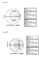
- Fig. 4a is a view showing Smith chart corresponding to Fig. 3a .
- Fig. 4b is a view showing Smith chart corresponding to Fig. 3b.
- Fig. 3a may show the matching characteristics of the frequency of the signal at a point "a" of the radiating metal.
- Fig. 3b may show the matching characteristics of the frequency of the signal at a point "b" of the radiating metal.
- a signal having a frequency between 700MHz and 2300MHz is transmitted to and received from the radiating metal 110 shown in Fig. 1
- the frequency and the matching characteristics at the point "a" in Fig. 1 can be represented as shown in Fig. 3a .
- Smith chart is represented as shown in Fig. 4a . That is, when the signal having a frequency of about 850MHz is transmitted to the radiating metal 110 and when the signal having a frequency of about 1850MHz is transmitted to the radiating metal 110, it can be seen that one Pole is formed respectively. Therefore, it can be understood that the transmission loss can be minimized when the signal having a frequency of about 850MHz and the signal having a frequency of about 1850MHz are transmitted to and received from the radiating metal 110.
- Fig. 3b The frequency and gain relationship at the point "b" in Fig. 1 may be represented as shown in Fig. 3b .
- Smith chart is represented as shown in Fig. 4b . Describing the frequency and gain relationship by using Figs. 3b and 4 , when a signal having a frequency between about 790 MHz and 980MHz is transmitted to the radiating metal 110 and when a signal having a frequency between about 1700 MHz and 2100MHz is transmitted to the radiating metal 110, it can be discovered that two Poles are formed respectively. In other words, two Poles are formed at the low frequency band and the high frequency band respectively by the first impedance 120 and the second impedance 130.
- the range of the frequency having a low transmission loss is increased and the signal having a broader band may be transmitted and received.
- the frequency is 1250MHz
- the signal which is transmitted to and received from the radiating metal is transmitted to the ground, so that the matching does not occur.
- Fig. 5 is a circuit diagram showing an antenna apparatus according to another embodiment of the present invention.
- Figs. 6a to 6c are equivalent circuit diagrams according to a signal which is transmitted to the antenna apparatus shown in Fig. 5.
- Fig. 6a is an equivalent circuit diagram of the antenna apparatus when the signal having a predetermined frequency is transmitted to the radiating metal.
- Fig. 6b is an equivalent circuit diagram of the antenna apparatus when the signal having a frequency greater than the predetermined frequency is transmitted to the radiating metal.
- Fig. 6c is an equivalent circuit diagram of the antenna apparatus when the signal having a frequency less than the predetermined frequency is transmitted to the radiating metal.
- an antenna apparatus 200 may include a radiating metal 210, a first impedance 220, a second impedance 230, a third impedance 240 and a fourth impedance 250.
- the first impedance 220 is connected between the radiating metal 210 and a ground (GND), has an impedance value which is changed depending on the frequency, and resonates in response to a predetermined frequency, so that an open-circuit occurs between the radiating metal 210 and the ground (GND).
- the second impedance 230 is connected between the radiating metal 210 and a ground (GND), has an impedance value which is changed depending on the frequency, and resonates in response to a predetermined frequency, so that a short-circuit occurs between the radiating metal 210 and the ground (GND).
- the third impedance 240 is connected in series to the radiating metal 210 and is opened in response to a predetermined frequency.
- the fourth impedance 250 is connected in series to the radiating metal 210 and is short-circuited in response to the predetermined frequency.
- the antenna apparatus 200 shown in Fig. 5 is different from the antenna apparatus 100 shown in Fig. 1 in that the antenna apparatus 200 further includes the third impedance 240 and the fourth impedance 250 which are connected in series to the radiating metal 210.
- the antenna apparatus 200 further includes the third impedance 240 and the fourth impedance 250 which are connected in series to the radiating metal 210.
- the impedance value of the third impedance 240 increases infinitely by resonance and the impedance value of the fourth impedance 250 becomes 0 by resonance, so that the antenna apparatus 200 may be represented as shown in Fig. 6a . That is, this may have the same effect as if the radiating metal 210 is disconnected by the third impedance 240.
- the radiating metal 210 is connected to the ground (GND) by the second impedance 230 and the radiating metal 210 is in the state that the radiating metal 210 is disconnected from an external device (not shown) by the third impedance 240, the signal is not transmitted to and received from the radiating metal 210, so that the signal transmitted to and received from the radiating metal 210 may not be transmitted to and received from the external device (not shown) connected to the antenna apparatus 200.
- the first impedance 220 and the third impedance 240 may have a capacitor component "C H2 " and a capacitor component “C H3 " respectively, and the second impedance 230 and the fourth impedance 250 may have an inductor component "L H2 " and an inductor component “L H3 “ respectively, so that the antenna apparatus 200 may be represented as shown in Fig. 6b . Therefore, the third impedance 240 and the fourth impedance 250 may be connected in series to the radiating metal 210.
- the high frequency band signal which is transmitted to and received from the radiating metal 210 may resonate by the capacitor component "C H3 " of the third impedance 240 connected in series to the radiating metal 210 and the inductor component "L H3 " of the fourth impedance 250 connected in series to the radiating metal 210, so that the high frequency band signal which is transmitted to and received from the radiating metal 210 may bypass the third impedance 240 and the fourth impedance 250.
- the first impedance 220 and the third impedance 240 may have inductor components, and the second impedance 230 and the fourth impedance 250 may have capacitor components, so that the antenna apparatus 200 may be represented as shown in Fig. 6c . Therefore, the third impedance 240 and the fourth impedance 250 may be connected in series to the radiating metal 210.
- the low frequency band signal which is transmitted to and received from the radiating metal 210 may resonate by the inductor component "L L3 " of the third impedance 240 connected in series to the radiating metal 210 and the capacitor component "C L3 " of the fourth impedance 250 connected in series to the radiating metal 210, so that the low frequency band signal which is transmitted to and received from the radiating metal 210 may bypass the third impedance 240 and the fourth impedance 250.
- one third impedance 240 and one fourth impedance 250 are shown, a plurality of the third impedances 240 and a plurality of the fourth impedances 250 may be provided without being limited to this.
- an inductor L31 and a capacitor C31 may be connected in parallel to each other.
- an inductor L41 and a capacitor C41 may be connected in series to each other.
- the low frequency band signal may have 850MHz and the high frequency band signal may have 1850MHz.
- the predetermined frequency may be 1250MHz.
- the antenna apparatus 100 can resonate in response to the high frequency band signal and can resonate in response to the low frequency band signal, thereby causing the high frequency band signal and the low frequency band signal to have a broader band.
- first, second, third and fourth impedances 220, 230, 240 and 250 are connected to the radiating metal 210, there is no limit to this. Only the first and second impedances 220 and 230 may be connected to the radiating metal 210, or only the third and fourth impedances 240 and 250 may be connected to the radiating metal 210.
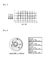
- Fig. 7 is a view showing matching characteristics of the frequency of a random signal which is transmitted to the antenna device shown in Fig. 5 .
- Fig. 8 is a view showing Smith chart corresponding to Fig. 7 .
- a signal having a frequency between 700MHz and 2300MHz is transmitted to and received from the radiating metal 210 shown in Fig. 5
- the frequency and gain relationship at the point "C" may be represented as shown in Fig. 7 .
- Smith chart is represented as shown in Fig. 8 .
- the range of the frequency capable of minimizing the transmission loss at one Pole is increased, so that it is possible to greatly increase the range of the frequency capable of minimizing the transmission loss of the signal which is transmitted to and received from the radiating metal 210. Accordingly, it can be understood that the signal becomes to have a broader band. It can be found that when the frequency is 1250MHz, the signal is transmitted to the ground and the matching does not occur.
- Fig. 9 is a structure view showing a structure of the antenna apparatus according to the present invention.
- an electrode 1200 is formed on a substrate 1100 and may be used as a ground.
- a first radiating metal 1300 may be formed on the substrate 1100 in one direction.
- a second radiating metal 1400 may be formed in a direction perpendicular to the direction in which the first radiating metal 1300 is formed.
- the first radiating metal 1300 may be longer than the second radiating metal 1400.
- the first radiating metal 1300, the second radiating metal 1400 and the electrode 1200 may be connected to a feed 1500.
- a signal having a low frequency band may be transmitted to and received from the first radiating metal 1300.
- a signal having a high frequency band may be transmitted to and received from the second radiating metal 1400.
- the frequency of the signal having a low frequency band may be 850MHz and the frequency of the signal having a high frequency band may be 1850MHz.
- a distance "d1" between the first radiating metal 1300 and the electrode 1200 may be 8mm and a distance "d2" between the second radiating metal 1400 and the electrode 1200 may be 3mm.
- the antenna apparatus has been described based on an Inverted L antenna, the antenna apparatus is not limited to this.
Landscapes
- Details Of Aerials (AREA)
- Filters And Equalizers (AREA)
- Transceivers (AREA)
Abstract
Description
- Embodiments relate to an antenna apparatus, and more particularly to an antenna apparatus capable of causing a high-frequency band and a low-frequency band to become broad bands.
- Mobile communication subscribers are annually increasing and mobile communication technologies are also developing. A mobile communication device uses recently Long Term Evolution (LTE) as well as Code Division Multiple Access (CDMA), Wideband Code Division Multiple Access (WCDMA) as a mobile communication standard. The mobile communication device also uses Global Positioning System (GPS) and Wi-Fi.
- The mobile communication device like a smartphone prefers a built-in antenna to an external antenna. The built-in antenna includes an Inverted F antenna, a Planar inverted F antenna, an Inverted L antenna, and a Planar inverted L antenna, etc.
- Further, the smartphone is required to process signals from various frequency bands according to a trend of the multi-functionality. Therefore, there is a necessity for the smartphone to be optimized for a low-frequency signal and a high-frequency signal and to minimize the transmission loss of the signal in the transmission/reception of the signal.
- One embodiment is an antenna apparatus that includes: a radiating metal; a first impedance which is connected between the radiating metal and a ground, has an impedance value which is changed depending on a frequency, and resonates in response to a predetermined frequency, so that an open-circuit occurs between the radiating metal and the ground; and a second impedance which is connected between the radiating metal and the ground, has an impedance value which is changed depending on a frequency, and resonates in response to the predetermined frequency, so that a short-circuit occurs between the radiating metal and the ground (GND).
- A first inductor and a first capacitor of the first impedance are connected in parallel to each other.
- A second inductor and a second capacitor of the second impedance are connected in series to each other.
- The first impedance becomes an inductor component in response to a signal having a frequency less than the predetermined frequency. The second impedance becomes a capacitor component in response to a signal having a frequency less than the predetermined frequency. The inductor component and the capacitor component resonate at the signal having a frequency less than the predetermined frequency.
- The first impedance becomes a capacitor component in response to a signal having a frequency greater than the predetermined frequency. The second impedance becomes an inductor component in response to a signal having a frequency greater than the predetermined frequency. The capacitor component and the inductor component resonate at the signal having a frequency greater than the predetermined frequency.
- The antenna apparatus includes a third impedance and a fourth impedance which are connected in series to the radiating metal. The third impedance is opened in response to the predetermined frequency. The fourth impedance is short-circuited in response to the predetermined frequency.
- A third inductor and a third capacitor of the third impedance are connected in parallel to each other.
- A fourth inductor and a fourth capacitor of the fourth impedance are connected in series to each other.
- The third impedance becomes an inductor component in response to a signal having a frequency less than the predetermined frequency. The fourth impedance becomes a capacitor component in response to a signal having a frequency less than the predetermined frequency. The inductor component and the capacitor component resonate at the signal having a frequency less than the predetermined frequency.
- The third impedance becomes a capacitor component in response to a signal having a frequency greater than the predetermined frequency. The fourth impedance becomes an inductor component in response to a signal having a frequency greater than the predetermined frequency. The capacitor component and the inductor component resonate at the signal having a frequency greater than the predetermined frequency.
- The radiating metal includes a first radiating metal which resonates in response to a signal having a lower frequency than the predetermined frequency, and includes a second radiating metal which resonates in response to a signal having a frequency greater than the predetermined frequency.
-
-
Fig. 1 is a circuit diagram showing an antenna apparatus according to an embodiment of the present invention; -
Figs. 2a to 2c are equivalent circuit diagrams according to a signal which is transmitted to the antenna apparatus shown inFig. 1 ; -
Figs. 3a and 3b are views showing matching characteristics of a frequency of a random signal which is transmitted to the antenna device shown inFig. 1 ; -
Fig. 4a is a view showing Smith chart corresponding toFig. 3a ; -
Fig. 4b is a view showing Smith chart corresponding toFig. 3b ; -
Fig. 5 is a circuit diagram showing an antenna apparatus according to another embodiment of the present invention; -
Figs. 6a to 6c are equivalent circuit diagrams according to a signal which is transmitted to the antenna apparatus shown inFig. 5 ; -
Fig. 7 is a view showing matching characteristics of a frequency of a random signal which is transmitted to the antenna device shown inFig. 5 ; -
Fig. 8 is a view showing Smith chart corresponding toFig. 7 ; and -
Fig. 9 is a structure view showing a structure of the antenna apparatus according to the present invention. - The following detailed description of the present invention shows a specified embodiment of the present invention and will be provided with reference to the accompanying drawings. The embodiment will be described in enough detail that those skilled in the art are able to embody the present invention. It should be understood that various embodiments of the present invention are different from each other and need not be mutually exclusive. For example, a specific shape, structure and properties, which are described in this disclosure, may be implemented in other embodiments without departing from the spirit and scope of the present invention with respect to one embodiment. Also, it should be noted that positions or placements of individual components within each disclosed embodiment may be changed without departing from the spirit and scope of the present invention. Therefore, the following detailed description is not intended to be limited. If adequately described, the scope of the present invention is limited only by the appended claims of the present invention as well as all equivalents thereto. Similar reference numerals in the drawings designate the same or similar functions in many aspects.
- Hereafter, an impedance matching circuit according to an embodiment of the present invention will be described with reference to the accompanying drawings.
-
Fig. 1 is a circuit diagram showing an antenna apparatus according to an embodiment of the present invention.Figs. 2a to 2c are equivalent circuit diagrams according to a signal which is transmitted to the antenna apparatus shown inFig. 1. Fig. 2a is an equivalent circuit diagram of the antenna apparatus when the signal having a predetermined frequency is transmitted to the radiating metal.Fig. 2b is an equivalent circuit diagram of the antenna apparatus when the signal having a frequency greater than the predetermined frequency is transmitted to the radiating metal.Fig. 2c is an equivalent circuit diagram of the antenna apparatus when the signal having a frequency less than the predetermined frequency is transmitted to the radiating metal. - Referring to
Fig. 1 , anantenna apparatus 100 may include a radiatingmetal 110, afirst impedance 120 and asecond impedance 130. Thefirst impedance 120 is connected between the radiatingmetal 110 and a ground (GND), has an impedance value which is changed depending on a frequency, and resonates in response to a predetermined frequency, so that an open-circuit occurs between the radiatingmetal 110 and the ground (GND). Thesecond impedance 130 is connected between the radiatingmetal 110 and the ground (GND), has an impedance value which is changed depending on a frequency, and resonates in response to the predetermined frequency, so that a short-circuit occurs between the radiatingmetal 110 and the ground (GND). - In the
antenna apparatus 100, a signal belonging to a low frequency band and a signal belonging to a high frequency band may resonate in one radiatingmetal 110. Also, in theantenna apparatus 100, two radiatingmetals 110 may transmit and receive the signal belonging to the low frequency band and the signal belonging to the high frequency band, respectively. In order that the signal belonging to the low frequency band and the signal belonging to the high frequency band may resonate in the radiatingmetal 110, thefirst impedance 120 and thesecond impedance 130 may be connected in parallel between the radiatingmetal 110 and the ground (GND). The impedance value of each of thefirst impedance 120 and thesecond impedance 130 may be changed in response to the frequency of the signal which is transmitted to the radiatingmetal 110. Also, each of thefirst impedance 120 and thesecond impedance 130 may resonate in response to a predetermined frequency. - When a signal having a predetermined frequency is transmitted to and received from the radiating
metal 110, thefirst impedance 120 and thesecond impedance 130 may resonate in response to the predetermined frequency respectively. When the transmitted/received signal resonates in thefirst impedance 120, the impedance value of thefirst impedance 120 may increase infinitely, and when the transmitted/received signal resonates in thesecond impedance 130, the impedance value of thesecond impedance 130 may become 0. When the impedance value of thefirst impedance 120 becomes infinite and the impedance value of thesecond impedance 130 becomes 0, the radiatingmetal 110 of theantenna apparatus 100 may be, as shown inFig. 2a , connected to the ground (GND). Accordingly, the signal transmitted to and received from the radiatingmetal 110 is transmitted to the ground (GND), so that the signal may not be transmitted to an external device (not shown) connected to theantenna apparatus 100. - When the signal belonging to a high frequency band having a frequency greater than the predetermined frequency is transmitted to and received from the radiating
metal 110, thefirst impedance 120 of theantenna apparatus 100 may, as shown inFig. 2b , have a capacitor component "CH1" and thesecond impedance 130 of theantenna apparatus 100 may have an inductor component "LH1". A specific high frequency band signal among the high frequency band signals which are transmitted to and received from the radiatingmetal 110 may resonate by the capacitor component "CH1" of thefirst impedance 120 and the inductor component "LH1" of thesecond impedance 130. - Also, when the signal belonging to a low frequency band having a frequency less than the predetermined frequency is transmitted to and received from the radiating
metal 110, thefirst impedance 120 of theantenna apparatus 100 may, as shown inFig. 2c , have an inductor component "LL1" and thesecond impedance 130 of theantenna apparatus 100 may have a capacitor component "CL1". A specific low frequency band signal among the low frequency band signals which are transmitted to and received from the radiatingmetal 110 may resonate by the inductor component "LL1" of thefirst impedance 120 and the capacitor component "CL1" of thesecond impedance 130. - The impedance component value of each of the
first impedance 120 and thesecond impedance 130 may change in response to the signal which is transmitted to and received from the radiatingmetal 110. Therefore, the impedance values of thefirst impedance 120 and thesecond impedance 130 when the signal belonging to the high frequency band is transmitted to and received from the radiatingmetal 110 may be different from those of thefirst impedance 120 and thesecond impedance 130 when the signal belonging to the low frequency band is transmitted to and received from the radiatingmetal 110. Although onefirst impedance 120 and onesecond impedance 130 are shown, a plurality of thefirst impedances 120 and a plurality of thesecond impedances 130 may be provided without being limited to this. - The impedance component values of the
first impedance 120 and thesecond impedance 130 may be changed according to the frequency of the signal which is transmitted to and received from the radiatingmetal 110. Therefore, the signal may resonate both when the signal belonging to the high frequency band is transmitted to and received from the radiatingmetal 110 by thefirst impedance 120 and thesecond impedance 130 and when the signal belonging to the low frequency band is transmitted to and received from the radiatingmetal 110 by thefirst impedance 120 and thesecond impedance 130. For example, the low frequency band signal resonating in the radiatingmetal 110 may have 850MHz and the high frequency band signal resonating in the radiatingmetal 110 may have 1850MHz. Also, the predetermined frequency may use the average frequency of the frequency of the low frequency band signal and the frequency of the high frequency band signal. However, there is no limit to this. A frequency close to the average frequency of the frequency of the low frequency band signal and the frequency of the high frequency band signal can be used. For example, when the frequency of the low frequency band signal is 850MHz and the frequency of the high frequency band signal is 1850MHz, the predetermined frequency may be 1250MHz. - In the embodiment, in the
first impedance 120, an inductor L11 and a capacitor C11 may be connected in parallel to each other. In thesecond impedance 130, an inductor L21 and a capacitor C21 may be connected in series to each other. - Therefore, the
antenna apparatus 100 can resonate in response to the high frequency band signal and can resonate in response to the low frequency band signal, thereby causing the high frequency band signal and the low frequency band signal to have a broader band. -
Figs. 3a and 3b are views showing matching characteristics of a frequency of a random signal which is transmitted to the antenna apparatus shown inFig. 1 .Fig. 4a is a view showing Smith chart corresponding toFig. 3a .Fig. 4b is a view showing Smith chart corresponding toFig. 3b. Fig. 3a may show the matching characteristics of the frequency of the signal at a point "a" of the radiating metal.Fig. 3b may show the matching characteristics of the frequency of the signal at a point "b" of the radiating metal. - When a signal having a frequency between 700MHz and 2300MHz is transmitted to and received from the radiating
metal 110 shown inFig. 1 , the frequency and the matching characteristics at the point "a" inFig. 1 can be represented as shown inFig. 3a . Also, Smith chart is represented as shown inFig. 4a . That is, when the signal having a frequency of about 850MHz is transmitted to the radiatingmetal 110 and when the signal having a frequency of about 1850MHz is transmitted to the radiatingmetal 110, it can be seen that one Pole is formed respectively. Therefore, it can be understood that the transmission loss can be minimized when the signal having a frequency of about 850MHz and the signal having a frequency of about 1850MHz are transmitted to and received from the radiatingmetal 110. Further, it can be found that when the frequency is 1250MHz, the matching does not occur. The frequency and gain relationship at the point "b" inFig. 1 may be represented as shown inFig. 3b . Also, Smith chart is represented as shown inFig. 4b . Describing the frequency and gain relationship by usingFigs. 3b and4 , when a signal having a frequency between about 790 MHz and 980MHz is transmitted to the radiatingmetal 110 and when a signal having a frequency between about 1700 MHz and 2100MHz is transmitted to the radiatingmetal 110, it can be discovered that two Poles are formed respectively. In other words, two Poles are formed at the low frequency band and the high frequency band respectively by thefirst impedance 120 and thesecond impedance 130. As a result, the range of the frequency having a low transmission loss is increased and the signal having a broader band may be transmitted and received. When the frequency is 1250MHz, the signal which is transmitted to and received from the radiating metal is transmitted to the ground, so that the matching does not occur. -
Fig. 5 is a circuit diagram showing an antenna apparatus according to another embodiment of the present invention.Figs. 6a to 6c are equivalent circuit diagrams according to a signal which is transmitted to the antenna apparatus shown inFig. 5. Fig. 6a is an equivalent circuit diagram of the antenna apparatus when the signal having a predetermined frequency is transmitted to the radiating metal.Fig. 6b is an equivalent circuit diagram of the antenna apparatus when the signal having a frequency greater than the predetermined frequency is transmitted to the radiating metal.Fig. 6c is an equivalent circuit diagram of the antenna apparatus when the signal having a frequency less than the predetermined frequency is transmitted to the radiating metal. - Referring to
Fig. 5 , anantenna apparatus 200 may include a radiatingmetal 210, afirst impedance 220, asecond impedance 230, athird impedance 240 and afourth impedance 250. Thefirst impedance 220 is connected between the radiatingmetal 210 and a ground (GND), has an impedance value which is changed depending on the frequency, and resonates in response to a predetermined frequency, so that an open-circuit occurs between the radiatingmetal 210 and the ground (GND). Thesecond impedance 230 is connected between the radiatingmetal 210 and a ground (GND), has an impedance value which is changed depending on the frequency, and resonates in response to a predetermined frequency, so that a short-circuit occurs between the radiatingmetal 210 and the ground (GND). Thethird impedance 240 is connected in series to the radiatingmetal 210 and is opened in response to a predetermined frequency. Thefourth impedance 250 is connected in series to the radiatingmetal 210 and is short-circuited in response to the predetermined frequency. - The
antenna apparatus 200 shown inFig. 5 is different from theantenna apparatus 100 shown inFig. 1 in that theantenna apparatus 200 further includes thethird impedance 240 and thefourth impedance 250 which are connected in series to the radiatingmetal 210. Here, only the differences from theantenna apparatus 100 shown inFig. 1 will be described. - When a signal having a predetermined frequency is transmitted to and received from the radiating
metal 210, the impedance value of thethird impedance 240 increases infinitely by resonance and the impedance value of thefourth impedance 250 becomes 0 by resonance, so that theantenna apparatus 200 may be represented as shown inFig. 6a . That is, this may have the same effect as if the radiatingmetal 210 is disconnected by thethird impedance 240. Accordingly, since the radiatingmetal 210 is connected to the ground (GND) by thesecond impedance 230 and the radiatingmetal 210 is in the state that the radiatingmetal 210 is disconnected from an external device (not shown) by thethird impedance 240, the signal is not transmitted to and received from the radiatingmetal 210, so that the signal transmitted to and received from the radiatingmetal 210 may not be transmitted to and received from the external device (not shown) connected to theantenna apparatus 200. - When the signal belonging to a high frequency band having a frequency greater than the predetermined frequency is transmitted to and received from the radiating
metal 210, thefirst impedance 220 and thethird impedance 240 may have a capacitor component "CH2" and a capacitor component "CH3" respectively, and thesecond impedance 230 and thefourth impedance 250 may have an inductor component "LH2" and an inductor component "LH3" respectively, so that theantenna apparatus 200 may be represented as shown inFig. 6b . Therefore, thethird impedance 240 and thefourth impedance 250 may be connected in series to the radiatingmetal 210. The high frequency band signal which is transmitted to and received from the radiatingmetal 210 may resonate by the capacitor component "CH3" of thethird impedance 240 connected in series to the radiatingmetal 210 and the inductor component "LH3" of thefourth impedance 250 connected in series to the radiatingmetal 210, so that the high frequency band signal which is transmitted to and received from the radiatingmetal 210 may bypass thethird impedance 240 and thefourth impedance 250. - When the signal belonging to a low frequency band having a frequency less than the predetermined frequency is transmitted to and received from the radiating
metal 210, thefirst impedance 220 and thethird impedance 240 may have inductor components, and thesecond impedance 230 and thefourth impedance 250 may have capacitor components, so that theantenna apparatus 200 may be represented as shown inFig. 6c . Therefore, thethird impedance 240 and thefourth impedance 250 may be connected in series to the radiatingmetal 210. The low frequency band signal which is transmitted to and received from the radiatingmetal 210 may resonate by the inductor component "LL3" of thethird impedance 240 connected in series to the radiatingmetal 210 and the capacitor component "CL3" of thefourth impedance 250 connected in series to the radiatingmetal 210, so that the low frequency band signal which is transmitted to and received from the radiatingmetal 210 may bypass thethird impedance 240 and thefourth impedance 250. Although onethird impedance 240 and onefourth impedance 250 are shown, a plurality of thethird impedances 240 and a plurality of thefourth impedances 250 may be provided without being limited to this. - In the embodiment, in the
third impedance 240, an inductor L31 and a capacitor C31 may be connected in parallel to each other. In thefourth impedance 250, an inductor L41 and a capacitor C41 may be connected in series to each other. Also, the low frequency band signal may have 850MHz and the high frequency band signal may have 1850MHz. Also, the predetermined frequency may be 1250MHz. - Therefore, the
antenna apparatus 100 can resonate in response to the high frequency band signal and can resonate in response to the low frequency band signal, thereby causing the high frequency band signal and the low frequency band signal to have a broader band. - In the above description, although all of the first, second, third and
fourth impedances metal 210, there is no limit to this. Only the first andsecond impedances metal 210, or only the third andfourth impedances metal 210. -
Fig. 7 is a view showing matching characteristics of the frequency of a random signal which is transmitted to the antenna device shown inFig. 5 .Fig. 8 is a view showing Smith chart corresponding toFig. 7 . - Referring to
Figs. 7 and 8 , when a signal having a frequency between 700MHz and 2300MHz is transmitted to and received from the radiatingmetal 210 shown inFig. 5 , the frequency and gain relationship at the point "C" may be represented as shown inFig. 7 . Also, Smith chart is represented as shown inFig. 8 . When a signal having a frequency of about 850MHz is transmitted to and received from the radiatingmetal 210 and when a signal having a frequency of about 1850MHz is transmitted to and received from the radiatingmetal 210, it can be discovered that the Pole is formed respectively. The range of the frequency capable of minimizing the transmission loss at one Pole is increased, so that it is possible to greatly increase the range of the frequency capable of minimizing the transmission loss of the signal which is transmitted to and received from the radiatingmetal 210. Accordingly, it can be understood that the signal becomes to have a broader band. It can be found that when the frequency is 1250MHz, the signal is transmitted to the ground and the matching does not occur. -
Fig. 9 is a structure view showing a structure of the antenna apparatus according to the present invention. - Referring to
Fig. 9 , in anantenna apparatus 1000, anelectrode 1200 is formed on asubstrate 1100 and may be used as a ground. Afirst radiating metal 1300 may be formed on thesubstrate 1100 in one direction. Asecond radiating metal 1400 may be formed in a direction perpendicular to the direction in which thefirst radiating metal 1300 is formed. Thefirst radiating metal 1300 may be longer than thesecond radiating metal 1400. Thefirst radiating metal 1300, thesecond radiating metal 1400 and theelectrode 1200 may be connected to afeed 1500. A signal having a low frequency band may be transmitted to and received from thefirst radiating metal 1300. A signal having a high frequency band may be transmitted to and received from thesecond radiating metal 1400. The frequency of the signal having a low frequency band may be 850MHz and the frequency of the signal having a high frequency band may be 1850MHz. A distance "d1" between thefirst radiating metal 1300 and theelectrode 1200 may be 8mm and a distance "d2" between thesecond radiating metal 1400 and theelectrode 1200 may be 3mm. - Also, here, although the antenna apparatus has been described based on an Inverted L antenna, the antenna apparatus is not limited to this.
- The features, structures and effects and the like described in the embodiments are included in at least one embodiment of the present invention and are not necessarily limited to one embodiment. Furthermore, the features, structures, effects and the like provided in each embodiment can be combined or modified in other embodiments by those skilled in the art to which the embodiments belong. Therefore, contents related to the combination and modification should be construed to be included in the scope of the present invention.
- Although embodiments of the present invention were described above, these are just examples and do not limit the present invention. Further, the present invention may be changed and modified in various ways, without departing from the essential features of the present invention, by those skilled in the art. For example, the components described in detail in the embodiments of the present invention may be modified. Further, differences due to the modification and application should be construed as being included in the scope and spirit of the present invention, which is described in the accompanying claims.
Claims (11)
- An antenna apparatus comprising:a radiating metal;a first impedance which is connected between the radiating metal and a ground, has an impedance value which is changed depending on a frequency, and resonates in response to a predetermined frequency, so that an open-circuit occurs between the radiating metal and the ground; anda second impedance which is connected between the radiating metal and the ground, has an impedance value which is changed depending on a frequency, and resonates in response to the predetermined frequency, so that a short-circuit occurs between the radiating metal and the ground (GND).
- The antenna apparatus of claim 1, wherein a first inductor and a first capacitor of the first impedance are connected in parallel to each other.
- The antenna apparatus of claim 1 or 2, wherein a second inductor and a second capacitor of the second impedance are connected in series to each other.
- The antenna apparatus of claim 1, wherein the first impedance becomes an inductor component in response to a signal having a frequency less than the predetermined frequency, wherein the second impedance becomes a capacitor component in response to a signal having a frequency less than the predetermined frequency, and wherein the inductor component and the capacitor component resonate at the signal having a frequency less than the predetermined frequency.
- The antenna apparatus of claim 1, wherein the first impedance becomes a capacitor component in response to a signal having a frequency greater than the predetermined frequency, wherein the second impedance becomes an inductor component in response to a signal having a frequency greater than the predetermined frequency, and wherein the capacitor component and the inductor component resonate at the signal having a frequency greater than the predetermined frequency.
- The antenna apparatus of claim 1, comprising a third impedance and a fourth impedance which are connected in series to the radiating metal, wherein the third impedance is opened in response to the predetermined frequency, and wherein the fourth impedance is short-circuited in response to the predetermined frequency.
- The antenna apparatus of claim 6, wherein a third inductor and a third capacitor of the third impedance are connected in parallel to each other.
- The antenna apparatus of claim 7, wherein a fourth inductor and a fourth capacitor of the fourth impedance are connected in series to each other.
- The antenna apparatus of claim 6, wherein the third impedance becomes an inductor component in response to a signal having a frequency less than the predetermined frequency, wherein the fourth impedance becomes a capacitor property in response to a signal having a frequency less than the predetermined frequency, and wherein the inductor component and the capacitor component resonate at the signal having a frequency less than the predetermined frequency.
- The antenna apparatus of claim 6, wherein the third impedance becomes a capacitor component in response to a signal having a frequency greater than the predetermined frequency, wherein the fourth impedance becomes an inductor component in response to a signal having a frequency greater than the predetermined frequency, and wherein the capacitor component and the inductor component resonate at the signal having a frequency greater than the predetermined frequency.
- The antenna apparatus of claim 1, wherein the radiating metal comprises a first radiating metal which resonates in response to a signal having a lower frequency than the predetermined frequency, and comprises a second radiating metal which resonates in response to a signal having a frequency greater than the predetermined frequency.
Applications Claiming Priority (1)
| Application Number | Priority Date | Filing Date | Title |
|---|---|---|---|
| KR1020130128212A KR101719551B1 (en) | 2013-10-28 | 2013-10-28 | Antenna apparatus |
Publications (1)
| Publication Number | Publication Date |
|---|---|
| EP2866300A1 true EP2866300A1 (en) | 2015-04-29 |
Family
ID=51830223
Family Applications (1)
| Application Number | Title | Priority Date | Filing Date |
|---|---|---|---|
| EP20140190614 Withdrawn EP2866300A1 (en) | 2013-10-28 | 2014-10-28 | Antenna apparatus |
Country Status (5)
| Country | Link |
|---|---|
| US (1) | US10074903B2 (en) |
| EP (1) | EP2866300A1 (en) |
| JP (2) | JP2015089129A (en) |
| KR (1) | KR101719551B1 (en) |
| CN (1) | CN104577359A (en) |
Families Citing this family (10)
| Publication number | Priority date | Publication date | Assignee | Title |
|---|---|---|---|---|
| US10034092B1 (en) | 2016-09-22 | 2018-07-24 | Apple Inc. | Spatial headphone transparency |
| CN109546310B (en) * | 2018-12-12 | 2021-01-08 | 维沃移动通信有限公司 | Antenna structure and communication terminal |
| KR102501647B1 (en) | 2019-01-10 | 2023-02-20 | 삼성전자 주식회사 | A mixer for reducing a local frequency signal generated at output of the mixer |
| CN110380189A (en) * | 2019-07-23 | 2019-10-25 | 广东以诺通讯有限公司 | A kind of miniature antenna and terminal |
| JP7356000B2 (en) * | 2019-08-14 | 2023-10-04 | ミツミ電機株式会社 | antenna device |
| US11166099B2 (en) | 2019-09-27 | 2021-11-02 | Apple Inc. | Headphone acoustic noise cancellation and speaker protection or dynamic user experience processing |
| US11361745B2 (en) | 2019-09-27 | 2022-06-14 | Apple Inc. | Headphone acoustic noise cancellation and speaker protection |
| US11206004B1 (en) * | 2020-09-16 | 2021-12-21 | Apple Inc. | Automatic equalization for consistent headphone playback |
| CN112583373B (en) * | 2020-12-08 | 2023-09-12 | 北京邮电大学 | Band-pass filter chip with frequency-dependent complex source and load |
| US11688383B2 (en) | 2021-08-27 | 2023-06-27 | Apple Inc. | Context aware compressor for headphone audio feedback path |
Citations (2)
| Publication number | Priority date | Publication date | Assignee | Title |
|---|---|---|---|---|
| US20040075614A1 (en) * | 2001-12-20 | 2004-04-22 | Yujiro Dakeya | Dual resonance antenna apparatus |
| US20060262028A1 (en) * | 2002-10-15 | 2006-11-23 | Ken Takei | Small multi-mode antenna and rf module using the same |
Family Cites Families (12)
| Publication number | Priority date | Publication date | Assignee | Title |
|---|---|---|---|---|
| JPH04233303A (en) | 1990-12-28 | 1992-08-21 | Matsushita Electric Ind Co Ltd | Antenna device |
| JP2000036721A (en) * | 1998-05-12 | 2000-02-02 | Nec Corp | Method and circuit for impedance matching |
| AU2002254159A1 (en) * | 2001-03-09 | 2002-09-24 | California Institute Of Technology | Switchless multi-resonant, multi-band power amplifier |
| JP4216124B2 (en) | 2002-12-12 | 2009-01-28 | 三菱電機株式会社 | Dual frequency matching circuit |
| JP2008054174A (en) * | 2006-08-28 | 2008-03-06 | Mitsubishi Electric Corp | 90-degree hybrid circuit |
| KR100782301B1 (en) * | 2006-09-21 | 2007-12-06 | 주식회사 이엠따블유안테나 | Antenna with adjustable resonant frequency using metamaterial and device comprising the same |
| KR100784411B1 (en) * | 2006-11-29 | 2007-12-11 | 전자부품연구원 | Front-end module for dual-band terminal |
| CN101569096A (en) * | 2007-08-29 | 2009-10-28 | 松下电器产业株式会社 | Double channel matching circuit |
| JP2009278192A (en) * | 2008-05-12 | 2009-11-26 | Sony Ericsson Mobilecommunications Japan Inc | Antenna device and communication terminal |
| KR101211870B1 (en) * | 2010-06-28 | 2012-12-13 | 박혜식 | The bamboo plywood |
| KR101217468B1 (en) * | 2010-11-03 | 2013-01-02 | 주식회사 네오펄스 | Inverted F Antenna With Parastic Coupling Resonance |
| CN202487756U (en) * | 2011-12-29 | 2012-10-10 | 惠州Tcl移动通信有限公司 | Mobile phone and double-frequency resonant antenna thereof |
-
2013
- 2013-10-28 KR KR1020130128212A patent/KR101719551B1/en active IP Right Grant
-
2014
- 2014-10-27 US US14/524,735 patent/US10074903B2/en active Active
- 2014-10-28 CN CN201410588697.9A patent/CN104577359A/en active Pending
- 2014-10-28 JP JP2014218803A patent/JP2015089129A/en active Pending
- 2014-10-28 EP EP20140190614 patent/EP2866300A1/en not_active Withdrawn
-
2016
- 2016-11-24 JP JP2016227746A patent/JP2017046360A/en active Pending
Patent Citations (2)
| Publication number | Priority date | Publication date | Assignee | Title |
|---|---|---|---|---|
| US20040075614A1 (en) * | 2001-12-20 | 2004-04-22 | Yujiro Dakeya | Dual resonance antenna apparatus |
| US20060262028A1 (en) * | 2002-10-15 | 2006-11-23 | Ken Takei | Small multi-mode antenna and rf module using the same |
Also Published As
| Publication number | Publication date |
|---|---|
| KR20150080931A (en) | 2015-07-13 |
| CN104577359A (en) | 2015-04-29 |
| US20150116167A1 (en) | 2015-04-30 |
| US10074903B2 (en) | 2018-09-11 |
| JP2017046360A (en) | 2017-03-02 |
| JP2015089129A (en) | 2015-05-07 |
| KR101719551B1 (en) | 2017-03-24 |
Similar Documents
| Publication | Publication Date | Title |
|---|---|---|
| EP2866300A1 (en) | Antenna apparatus | |
| US10461425B2 (en) | Antenna structure and wireless communication device using same | |
| US9680222B2 (en) | Antenna structure and wireless communication device using the same | |
| TWI628867B (en) | Antenna assembly and wireless communication device having the same | |
| US9673510B2 (en) | Antenna structure and wireless communication device using the same | |
| US9735471B2 (en) | Antenna structure and wireless communication device employing same | |
| US9401543B2 (en) | Broadband antenna | |
| US9887451B2 (en) | Antenna structure and wireless communication device using same | |
| AU2015244191B2 (en) | Capacitively-coupled isolator assembly | |
| EP2858171A1 (en) | Printed circuit board antenna and terminal | |
| US9287919B2 (en) | Multi-band isolator assembly | |
| US9780862B2 (en) | Antenna structure and wireless communication device using the same | |
| US20150214995A1 (en) | Semiconductor device, and transmission and reception circuit | |
| CN104752827A (en) | Double-feed antenna system and electronic equipment | |
| US10530056B2 (en) | Antenna structure and wireless communication device using same | |
| US11444594B2 (en) | Multiplexer | |
| WO2011026522A1 (en) | An antenna device and a portable radio communication device comprising such antenna device | |
| TW201616807A (en) | Impedance matching circuit | |
| US9425508B2 (en) | Antenna structure and wireless communication device using same | |
| US20130038500A1 (en) | Switching arrangement for an antenna device | |
| WO2011110216A1 (en) | An antenna device adapted for simultaneous reception of a first frequency band and a second frequency band |
Legal Events
| Date | Code | Title | Description |
|---|---|---|---|
| PUAI | Public reference made under article 153(3) epc to a published international application that has entered the european phase |
Free format text: ORIGINAL CODE: 0009012 |
|
| 17P | Request for examination filed |
Effective date: 20141125 |
|
| AK | Designated contracting states |
Kind code of ref document: A1 Designated state(s): AL AT BE BG CH CY CZ DE DK EE ES FI FR GB GR HR HU IE IS IT LI LT LU LV MC MK MT NL NO PL PT RO RS SE SI SK SM TR |
|
| AX | Request for extension of the european patent |
Extension state: BA ME |
|
| RBV | Designated contracting states (corrected) |
Designated state(s): AL AT BE BG CH CY CZ DE DK EE ES FI FR GB GR HR HU IE IS IT LI LT LU LV MC MK MT NL NO PL PT RO RS SE SI SK SM TR |
|
| 17Q | First examination report despatched |
Effective date: 20170418 |
|
| STAA | Information on the status of an ep patent application or granted ep patent |
Free format text: STATUS: THE APPLICATION IS DEEMED TO BE WITHDRAWN |
|
| 18D | Application deemed to be withdrawn |
Effective date: 20190328 |