EP2863825B1 - Mikrowellenthermometrie für mikrowellenablationssysteme - Google Patents
Mikrowellenthermometrie für mikrowellenablationssysteme Download PDFInfo
- Publication number
- EP2863825B1 EP2863825B1 EP13807072.7A EP13807072A EP2863825B1 EP 2863825 B1 EP2863825 B1 EP 2863825B1 EP 13807072 A EP13807072 A EP 13807072A EP 2863825 B1 EP2863825 B1 EP 2863825B1
- Authority
- EP
- European Patent Office
- Prior art keywords
- microwave
- temperature
- signal
- radiometer
- cable
- Prior art date
- Legal status (The legal status is an assumption and is not a legal conclusion. Google has not performed a legal analysis and makes no representation as to the accuracy of the status listed.)
- Active
Links
- 238000002679 ablation Methods 0.000 title claims description 132
- 238000004861 thermometry Methods 0.000 title claims description 77
- 230000005540 biological transmission Effects 0.000 claims description 85
- 238000000034 method Methods 0.000 claims description 65
- 230000008878 coupling Effects 0.000 claims description 23
- 238000010168 coupling process Methods 0.000 claims description 23
- 238000005859 coupling reaction Methods 0.000 claims description 23
- 230000000712 assembly Effects 0.000 claims description 10
- 238000000429 assembly Methods 0.000 claims description 10
- 230000001902 propagating effect Effects 0.000 claims description 7
- 230000008569 process Effects 0.000 claims description 3
- 210000001519 tissue Anatomy 0.000 description 80
- 238000005259 measurement Methods 0.000 description 34
- 238000010586 diagram Methods 0.000 description 29
- 239000012809 cooling fluid Substances 0.000 description 27
- 238000009529 body temperature measurement Methods 0.000 description 25
- 239000012530 fluid Substances 0.000 description 19
- 239000000523 sample Substances 0.000 description 18
- 230000037361 pathway Effects 0.000 description 16
- 238000001816 cooling Methods 0.000 description 13
- 238000011282 treatment Methods 0.000 description 13
- 210000004072 lung Anatomy 0.000 description 12
- 230000004913 activation Effects 0.000 description 10
- 238000001994 activation Methods 0.000 description 10
- 238000012544 monitoring process Methods 0.000 description 10
- 206010028980 Neoplasm Diseases 0.000 description 8
- 238000013500 data storage Methods 0.000 description 8
- 230000033001 locomotion Effects 0.000 description 8
- 239000004020 conductor Substances 0.000 description 7
- 238000012958 reprocessing Methods 0.000 description 7
- 210000004027 cell Anatomy 0.000 description 6
- 238000004891 communication Methods 0.000 description 6
- 125000004122 cyclic group Chemical group 0.000 description 6
- 230000001276 controlling effect Effects 0.000 description 5
- 230000005855 radiation Effects 0.000 description 5
- 230000003139 buffering effect Effects 0.000 description 4
- 230000000694 effects Effects 0.000 description 4
- 230000005670 electromagnetic radiation Effects 0.000 description 4
- 239000003550 marker Substances 0.000 description 4
- 238000012545 processing Methods 0.000 description 4
- 238000005070 sampling Methods 0.000 description 4
- 238000001356 surgical procedure Methods 0.000 description 4
- 230000006378 damage Effects 0.000 description 3
- 201000010099 disease Diseases 0.000 description 3
- 208000037265 diseases, disorders, signs and symptoms Diseases 0.000 description 3
- 239000000975 dye Substances 0.000 description 3
- 238000003384 imaging method Methods 0.000 description 3
- 230000003902 lesion Effects 0.000 description 3
- 230000005404 monopole Effects 0.000 description 3
- 230000029058 respiratory gaseous exchange Effects 0.000 description 3
- 230000001225 therapeutic effect Effects 0.000 description 3
- 210000004881 tumor cell Anatomy 0.000 description 3
- 230000000007 visual effect Effects 0.000 description 3
- 208000002193 Pain Diseases 0.000 description 2
- 238000004458 analytical method Methods 0.000 description 2
- 238000001574 biopsy Methods 0.000 description 2
- 230000008859 change Effects 0.000 description 2
- 230000006870 function Effects 0.000 description 2
- PCHJSUWPFVWCPO-UHFFFAOYSA-N gold Chemical compound [Au] PCHJSUWPFVWCPO-UHFFFAOYSA-N 0.000 description 2
- 239000010931 gold Substances 0.000 description 2
- 229910052737 gold Inorganic materials 0.000 description 2
- 238000002347 injection Methods 0.000 description 2
- 239000007924 injection Substances 0.000 description 2
- 230000000266 injurious effect Effects 0.000 description 2
- 238000003780 insertion Methods 0.000 description 2
- 230000037431 insertion Effects 0.000 description 2
- 230000010354 integration Effects 0.000 description 2
- 210000004224 pleura Anatomy 0.000 description 2
- 230000002829 reductive effect Effects 0.000 description 2
- 230000001105 regulatory effect Effects 0.000 description 2
- 239000000243 solution Substances 0.000 description 2
- 238000012546 transfer Methods 0.000 description 2
- 206010011224 Cough Diseases 0.000 description 1
- 208000019693 Lung disease Diseases 0.000 description 1
- 208000027418 Wounds and injury Diseases 0.000 description 1
- 230000006399 behavior Effects 0.000 description 1
- 230000033228 biological regulation Effects 0.000 description 1
- 201000011510 cancer Diseases 0.000 description 1
- 230000002596 correlated effect Effects 0.000 description 1
- 230000000875 corresponding effect Effects 0.000 description 1
- 230000003247 decreasing effect Effects 0.000 description 1
- 238000013461 design Methods 0.000 description 1
- 238000002405 diagnostic procedure Methods 0.000 description 1
- 239000003989 dielectric material Substances 0.000 description 1
- 238000006073 displacement reaction Methods 0.000 description 1
- 238000012976 endoscopic surgical procedure Methods 0.000 description 1
- 238000001914 filtration Methods 0.000 description 1
- 238000002594 fluoroscopy Methods 0.000 description 1
- 230000002496 gastric effect Effects 0.000 description 1
- 238000009217 hyperthermia therapy Methods 0.000 description 1
- 230000036512 infertility Effects 0.000 description 1
- 208000014674 injury Diseases 0.000 description 1
- 239000000976 ink Substances 0.000 description 1
- 230000001678 irradiating effect Effects 0.000 description 1
- 230000002427 irreversible effect Effects 0.000 description 1
- 238000012830 laparoscopic surgical procedure Methods 0.000 description 1
- 230000000670 limiting effect Effects 0.000 description 1
- 239000007788 liquid Substances 0.000 description 1
- 210000005228 liver tissue Anatomy 0.000 description 1
- 230000003211 malignant effect Effects 0.000 description 1
- 238000012986 modification Methods 0.000 description 1
- 230000004048 modification Effects 0.000 description 1
- 239000000615 nonconductor Substances 0.000 description 1
- 239000013307 optical fiber Substances 0.000 description 1
- 239000003973 paint Substances 0.000 description 1
- 210000004923 pancreatic tissue Anatomy 0.000 description 1
- 230000002093 peripheral effect Effects 0.000 description 1
- 238000010248 power generation Methods 0.000 description 1
- 238000005086 pumping Methods 0.000 description 1
- 238000007674 radiofrequency ablation Methods 0.000 description 1
- 210000005084 renal tissue Anatomy 0.000 description 1
- 238000002271 resection Methods 0.000 description 1
- 230000004044 response Effects 0.000 description 1
- 238000012552 review Methods 0.000 description 1
- 230000000630 rising effect Effects 0.000 description 1
- 230000011218 segmentation Effects 0.000 description 1
- 238000000926 separation method Methods 0.000 description 1
- 230000000391 smoking effect Effects 0.000 description 1
- 238000001228 spectrum Methods 0.000 description 1
- 238000002560 therapeutic procedure Methods 0.000 description 1
- 210000003437 trachea Anatomy 0.000 description 1
- 238000002604 ultrasonography Methods 0.000 description 1
- 238000012795 verification Methods 0.000 description 1
- 238000012800 visualization Methods 0.000 description 1
Images


Classifications
-
- A—HUMAN NECESSITIES
- A61—MEDICAL OR VETERINARY SCIENCE; HYGIENE
- A61B—DIAGNOSIS; SURGERY; IDENTIFICATION
- A61B18/00—Surgical instruments, devices or methods for transferring non-mechanical forms of energy to or from the body
- A61B18/18—Surgical instruments, devices or methods for transferring non-mechanical forms of energy to or from the body by applying electromagnetic radiation, e.g. microwaves
- A61B18/1815—Surgical instruments, devices or methods for transferring non-mechanical forms of energy to or from the body by applying electromagnetic radiation, e.g. microwaves using microwaves
-
- G—PHYSICS
- G01—MEASURING; TESTING
- G01J—MEASUREMENT OF INTENSITY, VELOCITY, SPECTRAL CONTENT, POLARISATION, PHASE OR PULSE CHARACTERISTICS OF INFRARED, VISIBLE OR ULTRAVIOLET LIGHT; COLORIMETRY; RADIATION PYROMETRY
- G01J5/00—Radiation pyrometry, e.g. infrared or optical thermometry
- G01J5/02—Constructional details
- G01J5/08—Optical arrangements
- G01J5/0837—Microantennas, e.g. bow-tie
-
- G—PHYSICS
- G01—MEASURING; TESTING
- G01K—MEASURING TEMPERATURE; MEASURING QUANTITY OF HEAT; THERMALLY-SENSITIVE ELEMENTS NOT OTHERWISE PROVIDED FOR
- G01K11/00—Measuring temperature based upon physical or chemical changes not covered by groups G01K3/00, G01K5/00, G01K7/00 or G01K9/00
- G01K11/006—Measuring temperature based upon physical or chemical changes not covered by groups G01K3/00, G01K5/00, G01K7/00 or G01K9/00 using measurement of the effect of a material on microwaves or longer electromagnetic waves, e.g. measuring temperature via microwaves emitted by the object
-
- G—PHYSICS
- G01—MEASURING; TESTING
- G01K—MEASURING TEMPERATURE; MEASURING QUANTITY OF HEAT; THERMALLY-SENSITIVE ELEMENTS NOT OTHERWISE PROVIDED FOR
- G01K13/00—Thermometers specially adapted for specific purposes
-
- G—PHYSICS
- G01—MEASURING; TESTING
- G01K—MEASURING TEMPERATURE; MEASURING QUANTITY OF HEAT; THERMALLY-SENSITIVE ELEMENTS NOT OTHERWISE PROVIDED FOR
- G01K7/00—Measuring temperature based on the use of electric or magnetic elements directly sensitive to heat ; Power supply therefor, e.g. using thermoelectric elements
- G01K7/02—Measuring temperature based on the use of electric or magnetic elements directly sensitive to heat ; Power supply therefor, e.g. using thermoelectric elements using thermoelectric elements, e.g. thermocouples
-
- H—ELECTRICITY
- H01—ELECTRIC ELEMENTS
- H01R—ELECTRICALLY-CONDUCTIVE CONNECTIONS; STRUCTURAL ASSOCIATIONS OF A PLURALITY OF MUTUALLY-INSULATED ELECTRICAL CONNECTING ELEMENTS; COUPLING DEVICES; CURRENT COLLECTORS
- H01R13/00—Details of coupling devices of the kinds covered by groups H01R12/70 or H01R24/00 - H01R33/00
- H01R13/66—Structural association with built-in electrical component
-
- A—HUMAN NECESSITIES
- A61—MEDICAL OR VETERINARY SCIENCE; HYGIENE
- A61B—DIAGNOSIS; SURGERY; IDENTIFICATION
- A61B18/00—Surgical instruments, devices or methods for transferring non-mechanical forms of energy to or from the body
- A61B2018/00571—Surgical instruments, devices or methods for transferring non-mechanical forms of energy to or from the body for achieving a particular surgical effect
- A61B2018/00577—Ablation
-
- A—HUMAN NECESSITIES
- A61—MEDICAL OR VETERINARY SCIENCE; HYGIENE
- A61B—DIAGNOSIS; SURGERY; IDENTIFICATION
- A61B18/00—Surgical instruments, devices or methods for transferring non-mechanical forms of energy to or from the body
- A61B2018/00636—Sensing and controlling the application of energy
- A61B2018/00642—Sensing and controlling the application of energy with feedback, i.e. closed loop control
-
- A—HUMAN NECESSITIES
- A61—MEDICAL OR VETERINARY SCIENCE; HYGIENE
- A61B—DIAGNOSIS; SURGERY; IDENTIFICATION
- A61B18/00—Surgical instruments, devices or methods for transferring non-mechanical forms of energy to or from the body
- A61B2018/00636—Sensing and controlling the application of energy
- A61B2018/00666—Sensing and controlling the application of energy using a threshold value
-
- A—HUMAN NECESSITIES
- A61—MEDICAL OR VETERINARY SCIENCE; HYGIENE
- A61B—DIAGNOSIS; SURGERY; IDENTIFICATION
- A61B18/00—Surgical instruments, devices or methods for transferring non-mechanical forms of energy to or from the body
- A61B2018/00636—Sensing and controlling the application of energy
- A61B2018/00696—Controlled or regulated parameters
- A61B2018/00702—Power or energy
-
- A—HUMAN NECESSITIES
- A61—MEDICAL OR VETERINARY SCIENCE; HYGIENE
- A61B—DIAGNOSIS; SURGERY; IDENTIFICATION
- A61B18/00—Surgical instruments, devices or methods for transferring non-mechanical forms of energy to or from the body
- A61B2018/00636—Sensing and controlling the application of energy
- A61B2018/00773—Sensed parameters
- A61B2018/00791—Temperature
- A61B2018/00821—Temperature measured by a thermocouple
-
- A—HUMAN NECESSITIES
- A61—MEDICAL OR VETERINARY SCIENCE; HYGIENE
- A61B—DIAGNOSIS; SURGERY; IDENTIFICATION
- A61B18/00—Surgical instruments, devices or methods for transferring non-mechanical forms of energy to or from the body
- A61B2018/00988—Means for storing information, e.g. calibration constants, or for preventing excessive use, e.g. usage, service life counter
-
- A—HUMAN NECESSITIES
- A61—MEDICAL OR VETERINARY SCIENCE; HYGIENE
- A61B—DIAGNOSIS; SURGERY; IDENTIFICATION
- A61B18/00—Surgical instruments, devices or methods for transferring non-mechanical forms of energy to or from the body
- A61B18/18—Surgical instruments, devices or methods for transferring non-mechanical forms of energy to or from the body by applying electromagnetic radiation, e.g. microwaves
- A61B18/1815—Surgical instruments, devices or methods for transferring non-mechanical forms of energy to or from the body by applying electromagnetic radiation, e.g. microwaves using microwaves
- A61B2018/1823—Generators therefor
-
- A—HUMAN NECESSITIES
- A61—MEDICAL OR VETERINARY SCIENCE; HYGIENE
- A61B—DIAGNOSIS; SURGERY; IDENTIFICATION
- A61B18/00—Surgical instruments, devices or methods for transferring non-mechanical forms of energy to or from the body
- A61B18/18—Surgical instruments, devices or methods for transferring non-mechanical forms of energy to or from the body by applying electromagnetic radiation, e.g. microwaves
- A61B18/1815—Surgical instruments, devices or methods for transferring non-mechanical forms of energy to or from the body by applying electromagnetic radiation, e.g. microwaves using microwaves
- A61B2018/183—Surgical instruments, devices or methods for transferring non-mechanical forms of energy to or from the body by applying electromagnetic radiation, e.g. microwaves using microwaves characterised by the type of antenna
-
- A—HUMAN NECESSITIES
- A61—MEDICAL OR VETERINARY SCIENCE; HYGIENE
- A61B—DIAGNOSIS; SURGERY; IDENTIFICATION
- A61B5/00—Measuring for diagnostic purposes; Identification of persons
- A61B5/01—Measuring temperature of body parts ; Diagnostic temperature sensing, e.g. for malignant or inflamed tissue
-
- A—HUMAN NECESSITIES
- A61—MEDICAL OR VETERINARY SCIENCE; HYGIENE
- A61B—DIAGNOSIS; SURGERY; IDENTIFICATION
- A61B5/00—Measuring for diagnostic purposes; Identification of persons
- A61B5/05—Detecting, measuring or recording for diagnosis by means of electric currents or magnetic fields; Measuring using microwaves or radio waves
- A61B5/0507—Detecting, measuring or recording for diagnosis by means of electric currents or magnetic fields; Measuring using microwaves or radio waves using microwaves or terahertz waves
Definitions
- the present disclosure relates to microwave thermometry in microwave ablation systems.
- Electromagnetic radiation can be used to heat and destroy tumor cells. Treatment may involve inserting ablation probes into tissues where cancerous tumors have been identified. Once the ablation probes are properly positioned, the ablation probes emit electromagnetic radiation into tissue surrounding the ablation probes.
- apparatus for use in ablation procedures include a power generation source, e.g., a microwave or radio frequency (RF) electrosurgical generator that functions as an energy source and a surgical instrument (e.g., microwave ablation probe having an antenna assembly) for directing energy to the target tissue.
- RF radio frequency
- the generator and surgical instrument are typically operatively coupled by a cable assembly having a plurality of conductors for transmitting energy from the generator to the instrument, and for communicating control, feedback and identification signals between the instrument and the generator.
- monopole and dipole antenna assemblies microwave energy generally radiates perpendicularly away from the axis of the conductor.
- Monopole antenna assemblies typically include a single, elongated conductor.
- a typical dipole antenna assembly includes two elongated conductors that are linearly-aligned and positioned end-to-end relative to one another with an electrical insulator placed therebetween.
- Helical antenna assemblies include helically-shaped conductor configurations of various dimensions, e.g., diameter and length.
- the main modes of operation of a helical antenna assembly are normal mode (broadside), in which the field radiated by the helix is maximum in a perpendicular plane to the helix axis, and axial mode (end fire), in which maximum radiation is along the helix axis.
- tissue ablation procedure may dictate a particular ablation volume in order to achieve a desired surgical outcome.
- Ablation volume is correlated with antenna design, antenna performance, antenna impedance, ablation time and wattage, and tissue characteristics, e.g., tissue impedance.
- thermoprobes such as thermocouples or optical fibers
- US 2007/0299488 discloses a catheter which contains a microwave transmitting antenna for irradiating a tissue in a patient.
- the catheter also contains a receiving antenna connected to a radiometer which detects thermal emissions from the tissue.
- the catheter is connected to a control unit by a cable.
- the cable is connected to the catheter and to the control unit by connectors.
- the control unit contains a microwave generator for supplying microwave energy to the transmitting antenna via the cable.
- the unit also contains a processor for processing signals transmitted to it by the cable form the radiometer for sensing the noise temperature of the tissue and to control the temperature of the catheter.
- the radiometer is connected to the receiving antenna via a conductor and a diplexer which isolates the noise temperature signal and feeds it to the radiometer.
- the present disclosure features a cable including a thermometry network module.
- the cable includes a microwave transmission line, a first cable connector assembly coupled to a first end of the microwave transmission line and a second cable connector assembly coupled to a second end of the microwave transmission line, and a thermometry network module disposed within the first cable connector assembly and coupled to the first end of the microwave transmission line.
- the thermometry network module includes a radiometer and a microwave coupling network configured to couple a portion of the signals propagating through the microwave transmission line to the radiometer. The radiometer may process the portion of the signals to determine a noise temperature signal.
- the cable may include a data bus coupled between the first and second cable connector assemblies.
- the thermometry network module may include a controller coupled to the data bus. The controller may determine a temperature value based on the noise temperature signal and transmit the temperature value to at least one component of a microwave ablation system connected to the first or second cable assembly.
- the cable may include a display driver and a display coupled to the display driver. The controller may determine a temperature value based on the noise temperature signal and control the display driver to display the temperature value.
- the cable may include a temperature selector for selecting a temperature at which the microwave signal is to be shut off.
- the controller may include a temperature value based on the noise temperature signal and transmit a shut off message to a microwave generator coupled to the cable via the data bus if the temperature value is greater than the selected temperature.
- the temperature value may represent a temperature of tissue being treated or a temperature of at least a portion of a microwave ablation system component.
- the cable may include a power supply line coupled between the first and second cable connector assemblies for carrying a power signal between the first and second cable connector assemblies.
- the present disclosure is generally directed to microwave ablation systems that incorporate a microwave thermometry network for monitoring the thermal characteristics of the microwave transmission network and the physiological environment surrounding a microwave applicator.
- Microwave radiometry is a technique for measuring electromagnetic energy considered as thermal radiation, and can be used to detect and measure microwave energy emanating from heat sources.
- the microwave ablation systems combine an antenna transmitting energy to ablate tissue (at a set "ablation frequency") with an antenna receiving thermal noise power emitted by heated tissue (at a set “radiometric frequency”) that can be translated into average temperature. If the radiometric frequency is high enough (e.g., 3-9 GHz), the temperature will be averaged over a small enough volume around the antenna (e.g., 1-3mm), allowing the antenna to be used as a thermocouple.
- ablate tissue at a set "ablation frequency”
- radiometric frequency e.g., 3-9 GHz
- the temperature will be averaged over a small enough volume around the antenna (e.g., 1-3mm), allowing the antenna to be used as a thermocouple.
- the microwave ablation systems use microwave thermometry in combination with the pre-existing transmission network of a microwave ablation system to enable thermal monitoring of tissue and microwave ablation system components without increasing the size of a microwave applicator's catheter or its shaft cross section.
- These systems provide real-time monitoring and feedback of tissue temperature, which enhances procedural outcomes through real-time verification of ablation progression, completeness, or lack of completeness.
- the monitoring of system component temperature allows for the microwave ablation system to insure adequate cooling is occurring throughout a procedure thereby preventing potential device failures or potential patient or user injury.
- proximal refers to that portion of the apparatus, or component of the apparatus, closer to the user and the term “distal” refers to that portion of the apparatus, or component thereof, farther from the user.
- Electromagnetic energy is generally classified by increasing energy or decreasing wavelength into radio waves, microwaves, infrared, visible light, ultraviolet, X-rays and gamma-rays.
- microwave generally refers to electromagnetic waves in the frequency range of 300 megahertz (MHz) (3 x 10 8 cycles/second) to 300 gigahertz (GHz) (3 x 10 11 cycles/second).
- ablation procedure generally refers to any ablation procedure, such as, for example, microwave ablation, radiofrequency (RF) ablation, or microwave or RF ablation-assisted resection.
- energy applicator generally refers to any device that can be used to transfer energy from a power generating source, such as a microwave or RF electrosurgical generator, to tissue.
- energy-delivery device generally refers to any transmission medium that can be used for the propagation of signals from one point to another.
- transmission line generally refers to any transmission medium that can be used for the propagation of signals from one point to another.
- fluid generally refers to a liquid, a gas or both.
- controller refers to any electrical device that employs digital and/or analog components to generate digital and/or analog signals to control or drive another device.
- controller may refer to a digital signal processor, a microcontroller, or a computer having a processor, a memory, and input/output ports for carrying out some of the methods described herein.
- FIG. 1 is a block diagram of a microwave ablation system 100.
- the microwave ablation system 100 includes a microwave applicator 110, microwave cables 120 and 125, a coupling circuit 130, a microwave generator 140, a filter 135, and a radiometer 160.
- the microwave generator 140 generates a microwave signal and outputs it to the microwave applicator 110 via the microwave cables 120 and 125.
- the microwave applicator 110 includes at least one antenna which emits microwave radiation when the microwave signal is applied to the antenna.
- the antenna may be disposed in a tumor so that the microwave radiation emitted from the antenna can ablate the tumor.
- the coupling circuit 130 is coupled between the microwave generator 140 and the microwave applicator 110 to provide a noise temperature signal or at least a portion of the signals propagating through the microwave cables 120 and 125 to the radiometer 160.
- the filter 135 isolates a noise temperature signal from the at least a portion of the microwave signal.
- the radiometer 160 samples the noise temperature signal and provides it to the controller 150.
- the controller 150 may convert the microwave noise temperature signal into a temperature reading by digitally sampling the microwave noise temperature signal using an analog-to-digital converter (ADC) and scaling the result.
- ADC analog-to-digital converter
- the controller 150 may also interface with a display to display the temperature reading as described in more detail below.
- the noise temperature measured by the radiometer 160 may be used to enable temperature feedback control.
- the feedback control may involve open loop control, e.g., user-based control, or closed loop control, e.g., for an autonomous system, to achieve a desired tissue effect and to improve the overall procedural outcome.
- the radiometer 160 and controller 150 may also be used to monitor the temperature of components of the microwave ablation system 100.
- the radiometer 160 and controller 150 may be used to monitor the temperature of the microwave cables 120 to insure adequate cooling and to avoid failures.
- FIG. 2 is a block diagram of a microwave ablation system 200.
- the microwave ablation system 200 includes a microwave generator 220 and a microwave applicator 210 coupled to the microwave generator 220.
- the microwave applicator 210 includes a microwave antenna 230 and a handle 240 coupled to the microwave antenna 230 to allow a clinician to manipulate the microwave antenna 230 during a microwave ablation procedure.
- the microwave antenna 230 may be embodied as an inflexible ablation catheter or a flexible ablation catheter to accommodate a specific surgical procedure, a specific luminal structure, specific target tissue, a clinician's preference, etc.
- an ablation catheter that is very flexible for movement through the relatively narrow airways of the lungs of a patient.
- an ablation catheter that is only slightly flexible, e.g., where the ablation catheter is needed to pierce or puncture tissue.
- microwave antenna 230 may employ other ablation catheter embodiments, either simplified or more complex in structural detail, without departing from the scope of the instant disclosure.
- the radiometer 160 is disposed as close as possible to the radiating portion of the microwave antenna 230 to limit unwanted noise from entering the radiometer 160.
- the radiometer 160 and the coupling circuit 130 are disposed within the handle 240 of the microwave applicator 210.
- the coupling circuit 130 is coupled between microwave feed transmission line and the antenna element to provide at least a portion of a microwave signal propagating in the antenna element to the radiometer 160.
- the radiometer 160 is coupled to the coupling circuit 130 and outputs a voltage signal V 0 that is proportional to the temperature of the environment surrounding the antenna 230, e.g., the tissue to be ablated. This voltage signal V 0 is provided to the microwave generator 220 via communication line 215.
- the coupling circuit 130 of FIGS. 1 and 2 may be any microwave coupling network which guides energy into the radiometer 160.
- FIGS. 3A-3C are block diagrams of exemplary embodiments of the coupling circuit 130 of FIGS. 1 and 2 .
- FIG. 3A is a block diagram of a directional coupler 300 which couples a portion of the signals propagating in the microwave transmission line to port 3. The portion of the signals is then provided to the radiometer, which measures a noise temperature signal in the portion of the signals.
- FIG. 3B is a block diagram of a switch 350 that switches between ports 2 and 3. In some embodiments, the switch 350 is normally switched to port 2 so that the microwave signal is provided to the microwave antenna and is periodically switched to port 3 at regular intervals so that the radiometer can obtain noise temperature measurements.
- the switch 350 may switch to port 3 at predetermined times during the microwave ablation procedure, e.g., near the beginning and near the end of a microwave ablation procedure.
- the switch 350 may include a solid-state switch, such as a diode switch, or a transfer-type switch, such as a mechanical relay.
- the coupling circuit 130 may alternatively include a T-network 375 having a first LC resonant band pass filter 380 for passing one or more noise temperature frequencies to the radiometer 160 and a second LC resonant band pass filter 385 for passing the microwave signal to the microwave applicator.
- FIG. 4A is a circuit block diagram of a radiometer 400, which may be employed in the microwave ablation systems of FIGS. 1 and 2 .
- the radiometer 400 includes a low-noise amplifier 402, a local oscillator 404, a frequency mixer 406, a band pass filter 408, an intermediate frequency (IF) amplifier 410, a detector 412, and an integrator 414.
- the low-noise amplifier 402 amplifies a noise temperature signal to obtain an amplified noise temperature signal.
- the local oscillator 404 produces a sine wave and the frequency mixer 406 mixes the amplified noise temperature signal with the sine wave to shift the noise temperature signal to an intermediate frequency (IF) that is lower than the frequency of the microwave signal.
- the intermediate frequency may be a frequency in the range from 100 Hz to 100 kHz, such as 10 kHz.
- the band pass filter 408 filters the signal output from the frequency mixer 406 and the IF amplifier 410 amplifies the filtered signal.
- the detector 412 detects the noise temperature signal and the integrator 414 integrates the detected noise temperature signal to provide a voltage signal that is proportional to the temperature of the environment surrounding the microwave antenna.
- the radiometer 400 may use an integrator having long integration times, e.g., 10 ms to 10 s, and a band pass filter having a narrow bandwidth B, e.g., ⁇ 35 MHz centered around 3.5 GHz.
- the voltage signal output from the radiometer 400 may be further processed to filter the signals propagating through the transmission network to obtain the noise temperature signal.
- the radiometer 400 may use time domain and/or frequency domain filtering techniques to isolate the noise temperature signal, the noise temperature signal of the tissue, and the noise temperature signal of the transmission network.
- FIG. 4B is a circuit block diagram of a radiometer 420 in accordance with another embodiment of the present disclosure.
- the radiometer 400 includes a switch 422 (also referred to as a "Dicke modulator") that switches between the microwave signal input 421 and a resistive load 424, which is maintained at a constant temperature T C .
- the resistive load 424 may be a thermocouple that is disposed in thermal communication with the transmission network so as to measure a temperature representative of the temperature of the transmission network.
- the resistive load 424 provides a reference temperature that is used to cancel out the noise temperature of the transmission network in order to isolate the noise temperature of the tissue.
- the switch may be a single pole, double throw switch.
- a reference generator 426 generates a control signal that is provided to the switch 422 via a switch driver 428 to control the switching frequency of the switch 422.
- the output from the switch 422 is fed to an amplifier 430 which amplifies a noise temperature signal passing into the microwave signal input 421 or the reference temperature signal passing into the load temperature signal input 424.
- the amplifier 430 may be a low noise amplifier so that the amplifier does not introduce noise into the noise temperature signal.
- the output from the amplifier 430 is fed to an envelope detector 432 that detects the amplitude of the noise temperature signal.
- the amplitude of the noise temperature signal is amplified by amplifier 434 and provided to a phase detector 436.
- the reference generator 426 controls the phase detector 436 so that it operates synchronously with the switching of the switch 422.
- the output from the phase detector 436 is then integrated by the integrator 438, which reduces the amplitude of fluctuations in the noise temperature signal.
- the reference generator 426 In operation, the reference generator 426 generates a square wave at a frequency higher (e.g., 30 to 1000Hz) than the frequency at which receiver gain variations occur.
- the switch driver 428 drives the switch 422 in accordance with the generated square wave. By doing this, the effect of the receiver gain variations, e.g., amplifier drift, on the received noise temperature is eliminated.
- FIG. 5 is a block diagram of a microwave thermometry network module 500 used in the microwave ablation system of FIG. 1 .
- the microwave thermometry network module 500 monitors the thermal characteristics of the microwave transmission network, e.g., the antenna, as well as the physiological environment, e.g., tissue, surrounding a microwave applicator.
- the microwave thermometry network module 500 includes a radiometer 510, a filter 520, transmission line connectors 580a and 580b, a transmission line 575 connected between the transmission line connectors 580a and 580b, and a coupling network 530 coupled to the transmission line 575.
- the coupling network 530 couples at least a portion of the signals propagating through the transmission line 575 to the filter 520. These signals include a high power microwave signal 582 and a noise temperature signal 584.
- the filter 520 filters the signals provided by the coupling network 530 to isolate the noise temperature signal 584.
- the filter 520 may isolate a high frequency noise temperature signal, e.g., a 4 GHz noise temperature signal, from a lower frequency high power microwave signal, e.g., a 2450MHz microwave signal.
- the filter 520 may further filter the noise temperature signal to obtain the noise temperature signal from the tissue and the noise temperature signal from components of the microwave ablation system, such as the noise temperature signal from the microwave transmission network.
- Time and/or frequency domain signal processing techniques can be used to separate out the high power microwave signal, the microwave noise temperature from the tissue, and the microwave noise temperature from components of the microwave ablation system.
- the filter 520 may employ a fast Fourier transform (FFT) to determine the amplitude of the noise temperature signal.
- FFT fast Fourier transform
- the filter 520 could be a variety of analog and digital electronic components intended to isolate the microwave signal from noise temperature signals.
- the filter 520 may be implemented using digital circuitry, in which case the filter 520 would include an analog-to-digital converter (ADC) for converting at least a portion of the microwave signal provided by the coupling network 530 into digital form.
- the digital circuitry may implemented in a digital signal processor or a field-programmable gate array (FPGA).
- Noise temperature signals may be further separated into noise temperatures from each of the sources of noise temperature in the microwave ablation system (e.g., cables, circulators, couplers, filters, connectors, amplifiers, etc) and sources from the tissue.
- the controller 540 can generate control signals, e.g., pulsing control signals, for controlling the microwave generator to adjust its output to improve or optimize the radiometer measurements as described, for example, in more detail below.
- the microwave thermometry network module 500 further includes the controller 540, a user interface (UI) 550, a display driver 560, a display 570, and data bus connectors 515a and 515b.
- the controller 540 receives the measured noise temperature data from the radiometer 510 and determines temperature information based on the measured noise temperature data. Under the control of the controller 540, the temperature information may be directly displayed to the user of the system via the display driver 560 and the display 570 to inform the user of the real-time status, e.g., the progress or completion, of a medical procedure.
- the controller 540 may also use the temperature information as an input to a feedback algorithm designed to optimize the overall therapeutic effectiveness of the system as well as to insure system robustness and patient and user safety.
- the real-time procedural monitoring performed by the microwave thermometry network module 500 may directly display a temperature value via the display 570 to the user which corresponds to the status of the ablation procedure, e.g., ablation completeness or incompleteness.
- the system robustness monitoring performed by the controller 540 may monitor the temperature of the microwave transmission network, i.e., the coaxial transmission lines and antenna, and limit microwave output power based on predetermined temperature limits placed on the microwave transmission network.
- the user interface (UI) 550 may provide various levels of interface between the thermometry network module 500 and other components of the microwave ablation system ranging from minimally interfaced to highly interfaced.
- the minimally interfaced thermometry network module 500 may display a temperature value to the user, in which case the interface to the thermometry network module would include power supply line connectors 525a and 525b for distributing power to the components of the thermometry network module 500 and other components of the microwave ablation system connected to the power supply line connectors 525a and 525b.
- the minimally interfaced thermometry network module 500 would also include the coupling network 530 for coupling to the transmission line 575.
- the highly interfaced thermometry network module would be a thermometry network module further including the controller 540 acting as the master controller of the microwave ablation system, in which case the interface to the thermometry network module 500 includes data bus connectors 515a and 515b through which mixed signal control and monitoring data is transmitted from the controller 540 to other components of the microwave ablation system connected to the thermometry network module 500 via the data bus connectors 515a and 515b.
- the controller 540 may send commands to the microwave generator via connector 515b to vary characteristics of the microwave signal or stop the generation of the microwave signal entirely.
- the microwave thermometry network module 500 of FIG. 5 may all reside in the same physical location within the microwave ablation system or the various elements of the microwave thermometry network module 500 may be located at different locations within the microwave ablation system, i.e., a split configuration.
- FIGS. 6 and 7 illustrate a split configuration of the microwave thermometry network module 500 of FIG. 5 .
- FIG. 6 is a measurement module 600 that includes components of the microwave thermometry network module 500 associated with the measurement of a noise temperature signal, which is coupled from the microwave transmission line 675 via the coupling network 530.
- the coupling network 530 may be implemented by any known microwave coupling scheme, such as the directional coupler 300 of FIG. 3A , the switch 350 of FIG. 3B , the T-network 375 of FIG. 3C , a band pass filter, or a diplexer.
- the filter 520 constrains the coupled microwave energy entering the radiometer 510 to that which represents the thermal parameter of interest.
- the filter 520 performs frequency spectrum selection and the radiometer 510 includes a detector, e.g., the detector 432 of FIG. 4B , for detecting the noise temperature signal.
- the measurement module 600 also includes connectors for interfacing with other components of the microwave ablation system.
- the measurement module 600 includes data bus connectors 615a and 615b through which a noise temperature signal may be transmitted to other components of the microwave ablation system connected to the measure module 600 via the data bus connectors 615a and 615b.
- the measurement module 600 also includes an input power supply line connector 625b for receiving power from another component of the microwave ablation system that is connected to the input power supply line connector 625b, and an output power supply connector 625a through which power is provided to still another component of the microwave ablation system connected to the power supply line connector 625a.
- the measurement module 600 further includes transmission line connectors 680a and 680b that are connected to both ends of a transmission line 575 of the thermometry network module.
- the transmission line connectors 680a and 680b are used for connecting the measurement module 600 between components of the microwave ablation system so that the coupling network 530 can obtain a portion of the microwave signal transmitted by the microwave generator 1000 to the microwave applicator 800.
- the measurement module 600 may be directly connected between the microwave generator 1000 and the microwave applicator 800.
- the measurement module 600 may be directly connected to the microwave applicator 800, but indirectly connected to the microwave generator 1000 by connecting to the microwave cable 900 which, in turn, is connected to the microwave generator 1000.
- FIG. 7 illustrates the control module 700 of the split configuration of the microwave thermometry network module 500 of FIG. 5 .
- the control module 700 includes elements associated with the "smarts" of the microwave thermometry network module 500 and the user interface (UI) electronics.
- the "smarts” include the controller 540, which receives temperature measurements, e.g., a noise temperature signal in digital form, from the radiometer 510 via a data bus connector 715 and reacts to the temperature information by controlling the microwave output to achieve a desired system response.
- the controller 540 may communicate with the microwave generator 1000 via the data bus connector 715 in a manner which improves radiometer 510 performance and accuracy.
- the controller 540 may control the microwave generator 1000 to pulse the high-power microwave therapeutic energy so that the radiometer can take noise temperature measurements between the pulses, as described in more detail below.
- the controller 540 which is coupled to a user interface 550, may alert the user to the thermal status, e.g., a displayed temperature value, or halt certain system functions, e.g., halt the MW power output, when limits or values are reached, such as a targeted tissue temperature or microwave applicator temperature limit for safety or for device robustness when, for example, any component of the microwave ablation system is misused.
- the controller 540 also includes a power supply line connector 725 for receiving power from another module of the microwave ablation system.
- the power supply line connector 725 may connect to the power supply line connector 1025b of the microwave generator 1000 of FIG. 10 to receive power from the power distribution unit 1045 of the microwave generator 1000.
- the microwave thermometry network modules 500, 600, and 700 of FIGS. 5-7 may be powered by a regulated power supply that is provided by one of the components of the microwave ablation system connected to the network modules.
- the microwave thermometry network modules 500, 600, and 700 may receive power from the power supply 1050 and the power regulator 1040 of the microwave generator 1000.
- these microwave thermometry network modules 500, 600, and 700 may be powered by their own power supply and power regulation circuitry, e.g., battery, solar, or mains supply.
- FIG. 8 is a block diagram of a microwave applicator 800 which delivers microwave therapeutic energy to tissue to treat a disease or undesirable medical condition associated with the tissue.
- the microwave applicator 800 includes a probe or antenna 810 for delivering microwave energy, an applicator circuit 820, a user interface 840, a handle or hub 830, input and output fluid cooling and buffering ports 850, a data bus connector 815, a power supply line connector 825, and a transmission line connector 880.
- the antenna 810 receives a microwave signal via the transmission line connector 880.
- the applicator circuit 820 may include a thermocouple buffer, a microwave activation switch, and/or memory (e.g., an EEPROM) storing device identification information.
- the thermocouple buffer converts voltage of a thermocouple (e.g., the thermocouples 2001, 2002, and 2004 of FIG. 20 ) into a buffered voltage representative of the thermocouple voltage, which is less sensitive to interference.
- the device identification information can be used by the microwave generator, e.g., the microwave generator 1000 of FIG. 10 , to ensure that only properly identified microwave applicators 800 are connected to the microwave generator.
- the memory may store operating parameters of the microwave applicator 800 (e.g., time, power, and dosage limits) and information regarding the usage of the microwave applicator 800. Usage monitoring may enable limiting re-use of the microwave applicator 800 beyond a single use of the device or a certain number of activations.
- the microwave activation switch is connected to a user-selectable activation button in the user interface 840. When a user selects the activation button, the microwave activation switch is closed to allow a microwave signal to propagate to the antenna 810 of the microwave applicator 800.
- the applicator circuit 820 is connected to the data bus connector 815 so that it can communicate with devices of the microwave ablation system that connect to the data bus connector 815. For example, the applicator circuit 820 may provide device identification information to a microwave generator connected to the data bus connector 815. The applicator circuit 820 also receives power via the power supply line connector 880.
- the input and output cooling and buffering ports 850 connect to a fluid system (not shown) that provides cooling fluid to the antenna 810 to control the size and shape of an ablation volume.
- the cooling fluid may include dielectric materials to control the transfer of power to the tissue.
- the fluid system may include a fluid reservoir, a fluid pump for pumping cooling fluid through the input and output cooling and buffering ports 850, tubing for carrying the cooling fluid, and sensors (not shown).
- An example of a fluid system is described in detail in commonly assigned U.S. Patent Application No. 12/566,299 , which is incorporated herein by reference.
- FIG. 9 is a block diagram of a cable 900 for carrying the high power microwave signal to the microwave applicator 800.
- the cable 900 which may be a reusable cable, includes cable circuitry 910, a user interface 920 which is connected to the cable circuitry 910, data bus connectors 915a and 915b, power supply line connectors 925a and 925b, and transmission line connectors 980a and 980b.
- the connectors 915a, 915b, 925a, 925b, 980a, and 980b may be configured to connect to corresponding connectors of any component of the microwave ablation system such as the microwave thermometry network module 500, the microwave applicator 800, the microwave generator 1000.
- the microwave thermometry network module 500 may be integrated into a reusable cable.
- the cable circuitry 910 may support device identification, thermocouple buffering, and/or microwave activation.
- the cable circuitry 910 may also communicate with other components in the microwave ablation system via the data bus connectors 915a and 915b.
- FIG. 10 is a block diagram of a microwave generator 1000.
- the microwave generator 1000 includes a microwave signal generator 1010, a microwave module amplifier 1020 coupled to the output of the microwave signal generator 1010, a transmission line connector 1082 coupled to the output of the microwave module amplifier, and a coaxial cable connector assembly for connecting to another cable, which is coupled to the microwave applicator 800 of FIG. 8 .
- the microwave signal generator 1010 generates a microwave signal, which is amplified by the microwave module amplifier 1020 to produce a high power microwave signal 582.
- the high power microwave signal 582 is output from the microwave generator 1000. via the transmission line connector 1082.
- the transmission line connector 1082 connects to another component of the microwave ablation system, e.g., the cable 900 of FIG. 9 , which carries the high power microwave signal 582 to a microwave applicator, e.g., the microwave applicator 800 of FIG. 8 .
- the microwave generator 1000 further includes a power system for powering the various components of the microwave ablation system.
- the power system includes a power supply 1050, a power regulator 1040, and a power distribution circuit 1045.
- the power supply 1050 converts alternating current (AC) from the mains supply connector 1078, which may connect to a standard AC outlet via a mains supply line (not shown), to direct current (DC).
- the power regulator 1040 converts the DC output from the power supply 1050 into regulated DC of various power levels.
- the power regulator 1040 provides low power DC to the microwave signal generator 1010, the system controller 1060, and the power distribution circuit 1045.
- the power distribution circuit 1045 provides power to power supply line connectors 1025a and 1025b for providing power to components that connect to the microwave generator 1000.
- the power distribution circuit 1045 provides low power DC to external control and monitoring circuitry, such as the control module 700 of FIG. 7 , via the power supply line connector 1025b.
- the power distribution circuit 1045 also provides low power DC to the microwave applicator 800 and other components of the microwave ablation system that connect directly or indirectly to the power supply line connectors 1025a and 1025b.
- the power regulator 1040 also provides high power DC to the microwave module amplifier 1020, which outputs a high power microwave signal 582 via the transmission line connector 1082.
- the system controller 1060 is connected to the microwave signal generator 1010 to control the phase, frequency, and other parameters of the microwave signal 582 output from the microwave module amplifier 1020.
- the system controller 1060 is also connected to the data bus connectors 1015a and 1015b to enable communications between the microwave generator 1000 and various components of the microwave ablation system that connect to the microwave generator 1000, including the microwave thermometry network module 500 of the present disclosure.
- the system controller 1060 may receive feedback signals through the data bus connectors 1015a and 1015b to control the parameters of the high power microwave signal 582.
- the controller 540 of the microwave thermometry network module 500 of FIG. 5 could control the high power microwave signal 582, e.g., by pulsing, halting, or varying the high power microwave signal 582.
- the microwave generator 1000 also includes input and output devices including a display 1030 and a display driver 1035.
- the system controller 1060 controls the display driver 1035 to display information regarding operation of the microwave ablation system on the display 1030.
- the microwave generator 1000 also includes a footswitch connector 1076 for connecting to a footswitch controller.
- the system controller 1060 receives command signals from the footswitch controller for controlling the output from the microwave generator 1000.
- the microwave generator 1000 also incorporates a temperature probe connector 1080 for connecting to a remote temperature probe (not shown). As described below, the remote temperature probe may be used to measure the temperature of the patient to obtain patient temperature measurements for calibrating the temperature measurements of the microwave thermometry network module 500.
- the temperature probe connector 1080 may also accept a T-type thermocouple arrangement. The controller of the microwave thermometry network module 500 could condition the radiometer output into a T-type signal. This feature could be used to display temperature to the user via a front panel 7-segment display.
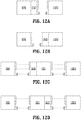
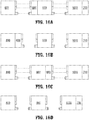
- FIGS. 11A-11C and 12A-12D illustrate different example configurations of the microwave ablation system using the microwave thermometry network module 500 of FIG. 5 .
- the thermometry network module 500 is disposed along the microwave transmission path between the microwave generator 1000 and the microwave applicator 800.
- FIGS. 11A-11C illustrate configurations in which the microwave thermometry network module 500 is a standalone component in a microwave ablation system that is divided into three or four separate components that are connectable to each other.
- the microwave thermometry network module is connectable between the microwave applicator and the microwave generator module.
- the configuration of FIG. 11A may be used in a portable microwave ablation system where, for example, the microwave generator 1000 and the microwave thermometry network module 500 are disposed in a handle of the portable microwave ablation system, the microwave applicator 800 is connectable to the handle, and the microwave thermometry network module 500 is connectable to the handle so that the microwave thermometry network module 500 connects between the microwave applicator 800 and the microwave generator 1000.
- the microwave thermometry network module is connectable to a distal end of the cable 900 and to the microwave applicator 800.
- the microwave thermometry network module 500 is connectable to the proximal end of the cable 900 and to the microwave generator 1000.
- FIGS. 12A-12D illustrate configurations in which the microwave thermometry network module 500 is integrated into any one of the components of a microwave ablation system that is divided into two or three separate components that are connectable to each other.
- the measurement module 600 is also standalone component that is connectable between the microwave applicator 800 and the microwave generator 1000.
- the microwave thermometry network module 500 is integrated into the microwave applicator 800.
- the microwave thermometry network module 500 is integrated into the microwave generator 1000.
- FIG. 12C the microwave thermometry network module 500 is integrated into the connector assembly at the distal end of the cable 900.
- the microwave thermometry network module 500 is integrated into the connector assembly at the proximal end of the cable 900.
- FIG. 13 is a perspective view of a standalone microwave thermometry network module 1300 that incorporates the circuitry of the microwave thermometry network module 500 shown in FIG. 5 .
- the microwave thermometry network module 1300 includes a connector 1320 at its proximal end for connecting directly to the microwave generator 1000, as shown in the configurations of FIGS. 11A and 11C , or for connecting to the microwave cable 900, as shown in the configuration of FIG. 11B .
- the first connector integrates a concentric data bus connector 1324 with a coaxial connector 1322 to enable communications between a thermometry network module 1300 and a microwave generator.
- the thermometry network module 1300 includes a display 1350 and a user interface having a selector 1330 and a switch 1360.
- the display 1350 displays the temperature that is determined, for example, by the controller 540 based on thermal measurements obtained by the radiometer 510 of the thermometry network module 500 of FIG. 5 .
- the selector 1330 includes a knob 1335 that allows a user to select a temperature limit at which microwave power is shutoff.
- the controller 540 may send a message to the microwave generator 1000 to shut off when the controller 540 determines that the measured temperature exceeds the selected temperature limit.
- the cable may include a switch (not shown) that opens when the controller 540 determines that the measured temperature exceeds the selected temperature limit to disconnect microwave power from the microwave applicator.
- the switch 1360 allows a user to turn on or shut off power to the microwave applicator 800.
- the display 1350 is a touch screen display and the selector 1330 and/or the switch 1360 are implemented as a "virtual" selector and/or switch in the touch screen display. In other embodiments, the selector 1330 and/or the switch 1360 are implemented as a physical selector and/or switch.
- the microwave thermometry network module 1300 includes another connector 1310 at its distal end for connecting directly to the microwave applicator 800, as shown in the configurations of FIGS. 11A and 11B , or for connecting to the microwave cable 900, as shown in the configuration of FIG. 11C . Similar to connector 1320, connector 1310 integrates a concentric data bus connector 1314 with a coaxial connector 1312 to enable communications between the thermometry network module 1300 and the microwave applicator 800. The connector 1310 may be configured to twist to lock or unlock connection with a microwave applicator.
- FIG. 14 is a perspective view of a microwave applicator 1400 that incorporates the microwave thermometry network module 500 of FIG. 5 into the microwave applicator's connector assembly 1405.
- the connector assembly 1405 is connected to a probe 1408 having a radiating portion 1410. Similar to FIG. 13 , the connector assembly 1405 includes a display that displays temperature measurements and a user interface that allows a user to change temperature settings and to shutoff microwave signals being provided to the probe 1408 to cause the radiating portion 1410 to emit microwave radiation.
- the connector assembly 1405 includes a connector 1406 similar to connectors 1310 and 1320 of FIG. 13 that is configured to connect directly to the microwave generator 1000, as shown in the configuration of FIG. 12A , or to connect to the microwave generator 1000. via a microwave cable. Temperature measurement data may be transmitted to the microwave generator 1000. via the data bus of the connector 1406.
- FIG. 15 is a perspective view of a microwave cable assembly 1500 according to an embodiment of the present disclosure including coaxial cable 1501, a connector assembly 1503 attached to the proximal end of the coaxial cable 1501 and a connector assembly 1505 attached to the distal end of the coaxial cable 1501.
- the components of the microwave thermometry network module 500 of FIG. 5 are incorporated into connector assembly 1505 of the microwave cable assembly 1500 as shown in the configuration of FIG. 12C .
- the connector assembly 1505 includes a display that displays temperature measurements and a user interface that allows a user to change temperature settings and to shutoff microwave signals being carried by the microwave cable assembly 1500.
- the microwave thermometry network module 500 may be incorporated into the connector assembly 1503 at the proximal end of the microwave cable assembly 1500 as shown in the configuration of FIG. 12D .
- the connector assemblies 1503 and 1505 include connectors 1504 and 1506, respectively, similar to the connectors 1310 and 1320 of FIG. 13 .
- connector 1504 is configured to connect directly to the microwave generator 1000 and connector 1506 is configured to connect directly to the microwave applicator 800.
- temperature data may be transmitted to the microwave generator 1000 via the data bus of connector 1504.
- Incorporating the components of the microwave thermometry network module 500 into a microwave cable minimizes the number of changes that need to be made to the microwave applicator 800 and/or the microwave generator 1000 to incorporate microwave thermometry according to the present disclosure.
- the circuitry of the system controller 1060 is simply reconfigured to receive temperature data from the controller 540 of the microwave thermometry network module 500.
- FIGS. 16A-16D and 17A-17D illustrate different example configurations of the microwave ablation system using the split configuration of the microwave thermometry network module as illustrated by FIGS. 6 and 7 .
- the measurement module 600 is disposed along the microwave transmission line between the microwave generator 1000 and the microwave applicator 800.
- the control module 700 may be disposed anywhere within the ablation system.
- FIGS. 16A-16D illustrate configurations in which the control module 700 is integrated into the microwave generator 1000 and the microwave ablation system is divided into three separate components that are connectable to each other.
- the measurement module 600 is integrated into the distal end of the cable 900.
- the measurement module 600 is integrated into the microwave applicator 800.
- the measurement module 600 is connectable to the proximal end of the cable 900.
- the measurement module is a standalone component that is connected between the microwave applicator and the microwave generator. The configuration of FIG.
- 12D may be used in a portable microwave ablation system where, for example, the microwave generator 1000 and the control module 700 are disposed in a handle of the portable microwave ablation system, the microwave applicator 800 is connectable to the handle, and the measurement module 600 is connectable to the handle so that the measurement module 600 connects between the microwave applicator 800 and the microwave generator 1000.
- FIGS. 17A-17D illustrate configurations in which the control module 700 is a standalone component that is connectable to the microwave generator 1000 and the microwave ablation system is divided into three or four separate components that are connectable to each other.
- the measurement module 600 is also standalone component that is connectable between the microwave applicator 800 and the microwave generator 1000.
- the measurement module 600 is integrated into the microwave applicator 800.
- the measurement module 600 is integrated into the distal end of the cable 900.
- the microwave ablation system is divided into three separate components in which the measurement module 600 is integrated into the microwave generator 1000.
- the configuration of FIG. 17D may be used in a portable microwave ablation system where, for example, the microwave generator 1000 and the measurement module 600 are disposed in a handle of the portable microwave ablation system, the microwave applicator 800 is connectable to the handle so that the microwave applicator 800 connects to the measurement module 600, and the control module 700 is connectable to the handle so that the control module 700 connects to the microwave generator 1000.
- FIG. 18 is a block diagram of a microwave ablation system 1800.
- the microwave ablation system 1 800 is the same as the microwave ablation system 100 shown in FIG. 1 except that the microwave ablation system 1800 includes filters 1802 and 1804, which are controlled by the controller 150.
- the first filter 1802 may separate the noise temperature signal from the high power microwave signal.
- the second filter 1804 may then extract the noise temperature of the tissue and the noise temperature of the transmission network from the noise temperature output from the first filter 1802.
- the controller 150 may provide tuning, gating, and other signals to control the manner in which the first filter 1802 and the second filter 1804 filter the microwave energy provided by the coupling circuit.
- the second filter 1804 may be further configured to separate out components of the transmission network noise temperature or the tissue noise temperature. For example, different components of the transmission network may produce noise temperature signals at different frequencies.
- the second filter 1804 may employ frequency domain techniques to determine the noise temperature of each of the components of the transmission network by analyzing the noise temperature signals at different frequencies.
- the second filter 1804 may alternatively employ both time domain and frequency domain techniques to isolate noise temperature signals from intentional sources, such as the microwave generator 1000, from other noise temperature sources, such as the cables and the tissue.
- the noise temperature from the transmission network may obscure the noise temperature of the tissue.
- the microwave signal output from the microwave generator may be turned off for an off period and the radiometer may monitor temperature during this off period.
- the transmission network may be cooled rapidly, either through ambient cooling or active fluid cooling, to allow for the separation of the transmission network noise temperature and the tissue noise temperature. Once the transmission network has cooled sufficiently, the radiometer may measure the temperature to obtain the noise temperature of the tissue.
- the magnitude of the noise temperature 1902 represents a combination of the noise temperatures of the transmission network and the tissue.
- the transmission network is cooled, either through ambient cooling or active fluid cooling, the magnitude of the noise temperature drops rapidly as illustrated by the steep slope 1904 of the noise temperature curve.
- the radiometer may measure the noise temperature to obtain the noise temperature of only the tissue.
- This rise in cooling fluid temperature would roll-off as the cooling fluid temperature equalizes to the tissue temperature. This roll-off point could further be used to indicate tissue temperature.
- FIG. 20 shows a microwave applicator 2000 having thermocouples for taking temperature measurements of the transmission network and the cooling fluid in order to determine when the magnitude of the temperature represents the tissue temperature.
- the microwave applicator 2000 includes a first thermocouple 2001 positioned at the fluid inlet 2011 for measuring the temperature of the fluid entering the fluid inlet 2011 and a second thermocouple 2002 positioned at the fluid outlet 2012 for measuring the temperature of the fluid exiting the fluid outlet 2012.
- the microwave applicator 2000 further includes a third thermocouple 2004 positioned at a suitable location along the transmission network to accurately measure a representative temperature of the transmission network.
- the third thermocouple 2004 may be positioned near the inner conductor 2008 of a coaxial cable connector 2006 of the transmission network.
- thermocouples 2001, 2002, and 2004 are used to measure the temperature of the cooling fluid and the transmission network in order to determine when the noise temperature measured by the radiometer represents the tissue temperature. These tissue measurements may be transmitted to a controller, e.g., the controller 540 of the thermometry network module 500 of FIG. 5 , outside of the microwave applicator 2000 via the communications interface 2010 so that the controller can control the radiometer measurements. Specifically, when the controller determines that the temperature of the transmission network as measured by thermocouple 2004 is the same as the temperature of the cooling fluid as measured by thermocouples 2001 and 2002, the transmission network no longer contributes to the noise temperature. The tissue may be the sole contributor to the noise temperature at this point in time. Thus, the controller may control the radiometer to measure the noise temperature at this point in time to obtain the tissue noise temperature.
- the controller may control the radiometer to measure the noise temperature to obtain tissue temperature measurements when the temperature of the cooling fluid flowing through the inlet (as measured by thermocouple 2001) is the same as the temperature of the cooling fluid flowing through the outlet (as measured by thermocouple 2002).
- the controller may control the radiometer to measure the noise temperature when the slope of the temperature curve settles to the tissue temperature slope 1908 of FIG. 19 as described in more detail below.
- FIGS. 21A and 21B are timing diagrams illustrating the timing of temperature measurements by the radiometer in accordance with other embodiments of the present disclosure.
- the microwave signal generated by the microwave generator may be a pulse-width modulated (PWM) signal 2102 at maximum generator peak power to provide variable average power.
- the sum of the off time 2104 and the on time 2106 define the period t of the PWM signal 2102, where 1/t is the PWM modulation frequency, which may be between 1 kHz and 100 kHz, and the microwave frequency is between 500 MHz and 15 GHz.
- the radiometer may sample 2108 the noise temperature of the microwave ablation system during the off times of the microwave PWM signal. So long as the duty cycle of the PWM signal is less than 100 percent, there are off times during which the radiometer can sample the noise temperature. By sampling the noise temperature during the off times, the noise temperature signal is isolated from the high power microwave therapy energy in time.
- the microwave ablation system may additionally turn off the microwave signal for an extended period of time (e.g., 5 to 60 seconds) allowing the system to cool (either actively or passively) and allowing the radiometer to measure a time-varying noise temperature curve as described above in FIG. 19 .
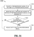
- the controller 150 of FIG. 18 may be configured to control the microwave generator 140 to generate a microwave signal 2202 that is a pulse-width modulated (PWM) signal for a first period 2212 and to turn off the PWM signal for a second period 2222.
- PWM pulse-width modulated
- the controller 150 or a controller of the microwave generator 140 may vary the duty cycle of the PWM signal to vary the output power.
- the controller 150 may control the radiometer 160 to measure noise temperature at various points 2204 along the microwave signal 2202 to obtain a noise temperature measurement signal 2206.
- the controller 150 may control the radiometer 160 to measure the noise temperature during the PWM off periods 2214 to monitor the maximum noise temperature of the microwave ablation system.
- the noise temperature measurements 2216 for the PWM off periods 2204 may be provided as feedback to a controller, e.g., the controller 540 of FIGS. 5 and 7 , which may control the microwave signal output from the microwave generator.
- the noise temperature measurements 2216 may be used by the controller 540 to reduce the duty cycle of the PWM signal 2212, to keep the transmission network temperatures within acceptable limits, to ensure adequate cooling of the microwave ablation system, or to prevent misuse.
- the controller 540 may determine whether any of the noise temperature measurements 2216 is greater than a predetermined noise temperature value, and may shut off the microwave signal or reduce the duty cycle of the PWM microwave signal if it is determined that any of the noise temperature measurements 2216 is greater than a predetermined noise temperature value.
- the radiometer may be configured to take a longer continuous sample 2224 during the second period 2222 when the microwave signal is turned off.
- the resulting noise temperature curve 2226 can be used to separate the various noise temperature contributions, e.g., separate the transmission network noise temperature from the tissue noise temperature, by observing the cooling behavior of the transmission network as described above.
- a system controller By shutting off the microwave PWM signal periodically, e.g., every 30-60 seconds, a system controller allows the transmission network and other components of the microwave ablation system to cool down and the system controller can avoid reducing the PWM signal's duty cycle in order to reduce the temperature the transmission network and other components of the system to a suitable temperature level.
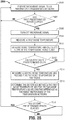
- FIG. 23 is a flowchart of a method 2300 for operating the microwave ablation system according to an embodiment of the present disclosure.
- a PWM microwave signal is provided to an antenna via a transmission network in step 2302.
- the PWM microwave signal may be generated by a microwave generator that adjusts the duty cycle of the PWM microwave signal to obtain a power level that achieves a desired tissue effect.
- the noise temperature is measured by a radiometer during the off periods of the PWM microwave signal.
- the PWM microwave signal is turned off in step 2308, which causes the transmission network to rapidly cool by a cooling fluid from a fluid cooling system of the microwave ablation system.
- the temperature of the cooling fluid and the temperature of the transmission network are measured, e.g., by the thermocouples 2001, 2002, and 2004 of FIG. 20 .
- the cooling fluid flowing around the radiator or antenna may make it difficult to measure the tissue noise temperature.
- Shutting off the flow of cooling fluid allows the tissue to heat the stagnant cooling fluid around the radiator or ablation zone, bringing the cooling fluid up to or near the temperature of the tissue, thus improving the accuracy of the tissue noise temperature measurement.
- the temperature curve of the cooling fluid e.g., the slope and maximum roll off
- the flow of cooling fluid is shut off may be used to indicate successful completion of tissue treatment.
- the noise temperature is measured by the radiometer and is recorded as the noise temperature of the tissue, in step 2314.
- the noise temperature of the tissue may be measured by the radiometer a predetermined amount of time after the flow of cooling fluid has been shut off.
- the method 2300 waits until the second predetermined period elapses before returning to step 2302 to turn on the PWM microwave signal.
- the second predetermined period may range between 5 seconds and 5 minutes.
- the second predetermined period may be varied throughout the ablation procedure. For example, a second predetermined period which is relatively short, e.g., 5 seconds, may be used several times during an ablation procedure to monitor the real-time progress of tissue treatment without significantly delaying the procedure time. During the shorter periods, the flow of fluid may be shut off for a short amount of time or the flow of fluid may not be shut off at all. Then, the second predetermined period may be longer, e.g., 5 minutes, following the ablation procedure to observe the final result of the ablation prcedure and confirm that the desired result was achieved. During the longer periods, the flow of fluid may be shut off.
- FIG. 24 is a flowchart of a method 2400 that may be employed together with the method of 2300 for controlling the temperature of the transmission network using the noise temperature measurements obtained by the radiometer during the off periods of the PWM microwave signal. for operating the microwave ablation system according to an embodiment of the present disclosure.
- a PWM microwave signal having a desired pulse width is provided to antenna via a transmission network in step 2302.
- step 2304 the noise temperature is measured by the radiometer during the off periods of the PWM microwave signal.
- step 2402 it is determined whether the noise temperature as measured by the radiometer is greater than a predetermined maximum temperature. If so, the duty cycle of the PWM microwave signal is reduced in step 2404 to cause the temperature of the transmission network to decrease.
- the flow rate of the cooling fluid may be increased so as to increase the cooling rate of the transmission network.
- the PWM microwave signal may be turned off for a predetermined period to allow the transmission network to cool.
- FIG. 25 is a flowchart of a method of operating the microwave ablation system according to another embodiment of the present disclosure.
- a microwave signal is provided to an antenna via a transmission network in step 2302.
- the first predetermined period may range between 3 seconds and 1 minute or longer depending on the procedure type. For example, for large volume ablation, the first predetermined period would be longer whereas for renal devervation, this period would be longer. If the first predetermined period has not elapsed, the method 2500 continues to provide a microwave signal to the antenna in step 2502.
- the microwave signal is turned off in step 2506 and a first noise temperature is measured by the radiometer in step 2508.
- the first noise temperature may be measured immediately after the microwave signal is turned off.
- the noise temperature is measured and the slope of a noise temperature curve is calculated.
- the slope of the noise temperature curve may be calculated based on the current noise temperature and one or more previous noise temperature measurements.
- step 2512 If it is determined in step 2512 that the calculated slope is approximately equal to the predetermined slope, a second noise temperature is measured by the radiometer and is recorded as the noise temperature of the tissue, in step 2514. In step 2516, the difference between the first noise temperature and the second noise temperature is determined and recorded as the noise temperature of the transmission network. Then, in step 2518, the method 2500 waits until the second predetermined period elapses before returning to step 2502 to turn on the microwave signal.
- the above-described microwave ablation systems are capable of directing microwave energy into tissue, and may be suitable for use in a variety of procedures and operations.
- the above-described microwave ablation systems may be suitable for utilization with hand-assisted, endoscopic and laparoscopic surgical procedures.
- the above-described microwave ablation systems may also be suitable for utilization in open surgical applications.
- An aspect of the present disclosure is the use of the microwave ablation systems described above used for treatment of cancers and other diseases of the lungs.
- Location and treatment of lung diseases, particularly cancers due to smoking, is quite challenging due to the tortuous paths of the lung passages, the extremely small size of peripheral lung passages, and the movement of the lungs during both diagnostic procedures and treatments.
- CT computed tomographic
- the microwave ablation systems may employ systems and methods for constructing, selecting and presenting pathway(s) to a target location within an anatomical luminal network in a patient. These systems and methods are particularly, but not exclusively, suited for guiding and navigating a probe, e.g., the microwave applicator 800 of FIG. 8 , through the bronchial airways of the lungs. These systems and methods include a preoperative and a operative component. The preoperative component is conducted prior to navigation and can be categorized as pathway planning. The operative component is conducted during navigation and can be categorized as navigation.
- the pathway planning phase includes three general steps, which are described in more detail in commonly assigned U.S. Application No. 13/834,581 entitled “MICROWAVE ENERGY-DELIVERY DEVICE AND SYSTEM,” and U.S. Application No. 13/838,805 entitled “PATHWAY PLANNING SYSTEM AND METHOD,”.
- the first step involves using a software graphical interface for generating and viewing a three-dimensional model of the bronchial airway tree ("BT").
- the second step involves using the software graphical interface for selection of a pathway on the BT, either automatically, semi-automatically, or manually, if desired.
- the third step involves an automatic segmentation of the pathway(s) into a set of waypoints along the path that can be visualized on a display.
- the airways are being used herein as an example of a branched luminal anatomical network.
- the term "BT” is being used in a general sense to represent any such luminal network and not to be construed to only refer to a bronchial tree, despite that the initials "BT" may not apply to other networks.
- CT data (images) may be employed for the route planning phase. CT data is also used for the navigation phase. CT data is preferable to other imaging modalities because it has its own system of coordinates. Matching the two systems of coordinates, that of the CT and that of the patient, is commonly known as registration. Registration is generally performed by identifying locations in both the CT and on or inside the body, and measuring their coordinates in both systems.
- Automatic registration techniques are described in detail in commonly assigned U.S. Patent Application No. 12/780,678 .
- Automatic registration between a digital image of a branched structure and a real-time indicator representing a location of a sensor inside the branched structure is achieved by using a sensor to "paint" a digital picture of the inside of the structure. Once enough location data has been collected, registration is achieved.
- the registration is “automatic” in the sense that navigation through the branched structure necessarily results in the collection of additional location data and, as a result, registration is continually refined.
- the system is ready to navigate a location sensor to the target within the patient's lungs.
- a computer provides a display identifying the target and depicting the virtual bronchoscopy image.
- appearing in each of the images on the display is the pathway from the current location of the location sensor to the target. This is the pathway that was established during the pathway planning phase discussed above.
- the pathway may be represented, for example, by a colored line. Also appearing in each image is a representation of the distal tip of the locatable guide and location sensor.
- the medical professional By advancing the locatable guide and following the pathway the medical professional is able to follow the identified pathway to the target.
- the virtual bronchoscopy image may not provide sufficient accuracy, particularly at the pleura boundaries of the lungs. In such instances the user can rely on the CT images to provide greater details.
- the target location is not.
- the target is generally considered fixed relative to the patient's body position which is monitored in real time by sensors.
- navigation accuracy may decrease as a result of cyclic chest movement resulting from breathing.
- precautions are taken to reduce the effects of this cyclic movement including reducing the respiration rate of the patient.
- this movement may be accounted for in the software by sampling the position sensors positions selectively so that measurements are only made at an extreme of a cyclic motion. The extremes of the motion of the patient's chest can readily be identified by the cyclic displacement of sensors during the breathing cycle.
- the maximum exhalation state for measurements since this state typically remains steady for a relatively larger proportion of the breath cycle than the maximum inhalation state.
- measurements can be taken continuously, and the cyclic variations eliminated or reduced by additional processing.
- This processing may include applying a low-frequency filter to the measurements.
- an average of the measurements over a time period of the cyclic motion may be calculated and used to assist in approximating the location of the target. This is assisted by knowing whether the CT data was derived with the patient in a fully inhaled or exhaled position, which can be used for comparison and greater approximation of positioning.
- the locatable guide is preferably removed, leaving a sheath in place as a guide channel for bringing a tool, e.g., the microwave applicator 800, to the target location.
- a tool e.g., the microwave applicator 800
- the planning and navigation systems and methods of the present disclosure may employ markers. These markers can be used for a variety of purposes including identifying tumors and lesions for follow-up analysis and monitoring, to identify locations that biopsy sampling has been undertaken, and to identify the boundaries or he center of a tumor or lesion for application of treatment. Other uses will be understood by those of skill in the art as falling within the scope of the present disclosure.
- the placement of markers can be particularly useful in the context of performing a video assisted thoracoscopic surgery (VATS) lung procedure, which is described in more detail in commonly assigned U.S. Application No. 13/834,581 , the disclosure of which is incorporated herein by reference.
- VATS video assisted thoracoscopic surgery
- a variety of techniques for identification of the location of implanted markers can be employed including fluoroscopy, ultrasound, and other imaging modalities. These are particularly useful when the marker is equipped with a radio-opaque portion, formed of, for example, gold.
- VATS procedures in particular lend themselves to visual identification, particularly when performing treatment of tissues near the pleura boundaries of the lungs.
- Some techniques to improve visualization involve the injection of inks or dyes into the patient to identify the location of the marker. These techniques tend to be more of a clinician based ad hoc solution to visual identification.
- markers of any kind can be very difficult.
- traditional dyes and solutions tend to be spread too broadly for accurate identification of the tissue to be identified, particularly if the marker is placed more than a few hours before the surgical procedure. Typically surgery must be undertaken within 72 hours of dye injection.
- Gold fiducial markers on the other hand are difficult if not impossible to identify without some imaging modality, and sometimes currently available fiducial markers tend to migrate over time, or even as a result of a patient cough.
- one embodiment of the planning and navigation systems and methods is directed to placement of a marker to promote visual identification of the tissue of interest during VATS and so that the tissue can be percutaneously ablated using the microwave ablation systems described above.
- embodiments of the present disclosure are equally applicable for use in treatment of other tissues.
- the systems and methods of the present disclosure may be used to treat liver tissue, kidney tissue, pancreatic tissue, gastrointestinal tissue, interstitial masses, and other portions of the body known to those of skill in the art to be treatable via microwave ablation.
- the microwave applicators which may be embodied as handpieces, cables, and thermometry modules (generally referred to as devices) described in the present disclosure may include one or more data storage components (e.g., EEPROM, PROM, etc.) capable of storing data therein for identifying the device.
- the stored data may include identification data of the device as well as data related to usage of the device (e.g., number of activations or time stamps of usage) and data related to reprocessing of the device.
- the data read from the data storage component may be read by other components of the system, such as the microwave generator 1000 of FIG. 10 , to ensure that the device is compatible with the other components of the system, is permitted to operate in a particular geographic location, has not exceeded a defined usage count or usage time, and is reasonably assured of being sterile.
- the device may alternatively include a bar code identifying the device and a microwave generator or other component of the microwave ablation system may include a bar code reader for reading identification data from the bar code.
- the bar code reader may then provide the read identification data to a computer connected to the bar code reader so that the computer can track the use of the device.
- One method of preventing unintended usage of a device is to limit the number of usages before requiring reprocessing of the device.
- a time stamp may be written to a data field of a data storage component. This data field may be continually checked to ensure that too great a period of time has not elapsed since that time stamp. Either simultaneously with the connection/activation of the device or following the expiry of the permitted usage time from the initial time stamp, data may be written to a separate data field in the data storage component.
- Reprocessing may be performed in an authorized reprocessing facility where the device may be inspected, worn parts may be replaced, data stored on the data storage components may be read, and the device may be sterilized.
- the data read from the data storage component may be sent back to the original manufacturer for review and analysis.
- the data storage component may include a data field identifying the number of times the device has been reprocessed. This data field is updated each time the device is reprocessed.
- the number of times a device may be reprocessed may be limited as well. Accordingly upon reaching the specified limit the device must be completely destroyed.
- the time stamp described above from insertion into another component or first activation may be overwritten and thus the device upon next insertion into another component is usable. While described generally herein, with respect to a limited example, reprocessing may under take a variety of schemes and a number of data fields on the data storage component may be read, overwritten, or have data written to them to ensure the safety and sterility of the devices.
Claims (6)
- Kabel (1500), welches Folgendes umfasst:eine Mikrowellen-Übertragungsleitung,eine erste Kabelverbinderbaugruppe (1505), die mit einem ersten Ende der Mikrowellen-Übertragungsleitung verbunden ist, und eine zweite Kabelverbinderbaugruppe (1503), die mit einem zweiten Ende der Mikrowellen-Übertragungsleitung verbunden ist, undein Thermometrie-Netzwerkmodul (500), das innerhalb der ersten Kabelverbinderbaugruppe (1505) angeordnet und mit dem ersten Ende der Mikrowellen-Übertragungsleitung verbunden ist, wobei das Thermometrie-Netzwerkmodul ein Radiometer (510) und ein Mikrowellen-Kopplungsnetzwerk (530, 520) aufweist, das dazu ausgebildet ist, einen Teil eines sich durch die Mikrowellen-Übertragungsleitung ausbreitenden Mikrowellensignals an das Radiometer (510) anzukoppeln, wobei das Radiometer dazu ausgebildet ist, den Teil des Mikrowellensignals zu verarbeiten, um ein Rauschtemperatursignal zu bestimmen.
- Kabel nach Anspruch 1, ferner umfassend einen zwischen der ersten und der zweiten Kabelverbinderbaugruppe geschalteten Datenbus, wobei das Thermometrie-Netzwerkmodul (500) ferner eine mit dem Datenbus verbundene Steuerung (540) aufweist, die dazu ausgebildet ist, einen Temperaturwert auf Grundlage des Rauschtemperatursignals zu bestimmen und den Temperaturwert zu mindestens einer Komponente eines Mikrowellenablationssystems zu übertragen, das mit der ersten oder der zweiten Kabelbaugruppe verbunden ist.
- Kabel nach Anspruch 2, ferner umfassend einen Anzeigetreiber (560) und eine mit dem Anzeigetreiber verbundene Anzeige (570), wobei die Steuerung (540) dazu ausgebildet ist, einen Temperaturwert auf Grundlage des Rauschtemperatursignals zu bestimmen, und den Anzeigetreiber zum Anzeigen des Temperaturwerts ansteuert.
- Kabel nach Anspruch 2 oder 3, ferner umfassend einen Temperaturwähler (1330) zum Auswählen einer Temperatur, bei der das Mikrowellensignal abzuschalten ist, wobei die Steuerung dazu ausgebildet ist, einen Temperaturwert auf Grundlage des Rauschtemperatursignals zu bestimmen, und eine Abschaltmeldung an einen mit dem Kabel über den Datenbus verbundenen Mikrowellengenerator überträgt, wenn der Temperaturwert größer als die ausgewählte Temperatur ist.
- Kabel nach Anspruch 2, 3 oder 4, wobei der Temperaturwert eine Temperatur des behandelten Gewebes oder eine Temperatur eines Teils einer Komponente des Mikrowellenablationssystems darstellt.
- Kabel nach Anspruch 1, 2, 3 oder 4, ferner umfassend eine Leistungsversorgungsleitung, die zwischen der ersten und der zweiten Kabelverbinderbaugruppe angeschlossen und dazu ausgebildet ist, ein Leistungssignal zwischen der ersten (1505) und der zweiten (1503) Kabelverbinderbaugruppe zu führen.
Applications Claiming Priority (4)
| Application Number | Priority Date | Filing Date | Title |
|---|---|---|---|
| US201261663099P | 2012-06-22 | 2012-06-22 | |
| US201361809634P | 2013-04-08 | 2013-04-08 | |
| US201361837633P | 2013-06-20 | 2013-06-20 | |
| PCT/US2013/047130 WO2013192561A1 (en) | 2012-06-22 | 2013-06-21 | Microwave thermometry for microwave ablation systems |
Publications (3)
| Publication Number | Publication Date |
|---|---|
| EP2863825A1 EP2863825A1 (de) | 2015-04-29 |
| EP2863825A4 EP2863825A4 (de) | 2016-08-03 |
| EP2863825B1 true EP2863825B1 (de) | 2018-02-21 |
Family
ID=49769441
Family Applications (4)
| Application Number | Title | Priority Date | Filing Date |
|---|---|---|---|
| EP13806962.0A Active EP2863824B1 (de) | 2012-06-22 | 2013-06-21 | Mikrowellenthermometrie für mikrowellenablationssysteme |
| EP13807072.7A Active EP2863825B1 (de) | 2012-06-22 | 2013-06-21 | Mikrowellenthermometrie für mikrowellenablationssysteme |
| EP17183926.9A Withdrawn EP3266400A3 (de) | 2012-06-22 | 2013-06-21 | Mikrowellenthermometrie für mikrowellenablationssysteme |
| EP13806592.5A Active EP2863823B1 (de) | 2012-06-22 | 2013-06-21 | Mikrowellenthermometrie für mikrowellenablationssysteme |
Family Applications Before (1)
| Application Number | Title | Priority Date | Filing Date |
|---|---|---|---|
| EP13806962.0A Active EP2863824B1 (de) | 2012-06-22 | 2013-06-21 | Mikrowellenthermometrie für mikrowellenablationssysteme |
Family Applications After (2)
| Application Number | Title | Priority Date | Filing Date |
|---|---|---|---|
| EP17183926.9A Withdrawn EP3266400A3 (de) | 2012-06-22 | 2013-06-21 | Mikrowellenthermometrie für mikrowellenablationssysteme |
| EP13806592.5A Active EP2863823B1 (de) | 2012-06-22 | 2013-06-21 | Mikrowellenthermometrie für mikrowellenablationssysteme |
Country Status (7)
| Country | Link |
|---|---|
| US (6) | US9127989B2 (de) |
| EP (4) | EP2863824B1 (de) |
| JP (5) | JP6236441B2 (de) |
| CN (3) | CN104487013B (de) |
| AU (4) | AU2013278080B2 (de) |
| CA (3) | CA2877565A1 (de) |
| WO (3) | WO2013192561A1 (de) |
Families Citing this family (58)
| Publication number | Priority date | Publication date | Assignee | Title |
|---|---|---|---|---|
| US8361067B2 (en) | 2002-09-30 | 2013-01-29 | Relievant Medsystems, Inc. | Methods of therapeutically heating a vertebral body to treat back pain |
| US7258690B2 (en) | 2003-03-28 | 2007-08-21 | Relievant Medsystems, Inc. | Windowed thermal ablation probe |
| US6907884B2 (en) | 2002-09-30 | 2005-06-21 | Depay Acromed, Inc. | Method of straddling an intraosseous nerve |
| WO2007112081A1 (en) | 2006-03-24 | 2007-10-04 | Micrablate | Transmission line with heat transfer ability |
| US11389235B2 (en) | 2006-07-14 | 2022-07-19 | Neuwave Medical, Inc. | Energy delivery systems and uses thereof |
| US10376314B2 (en) | 2006-07-14 | 2019-08-13 | Neuwave Medical, Inc. | Energy delivery systems and uses thereof |
| CA2957010C (en) | 2008-09-26 | 2017-07-04 | Relievant Medsystems, Inc. | Systems and methods for navigating an instrument through bone |
| US10028753B2 (en) | 2008-09-26 | 2018-07-24 | Relievant Medsystems, Inc. | Spine treatment kits |
| DK2459096T3 (en) | 2009-07-28 | 2015-01-19 | Neuwave Medical Inc | ablation device |
| EP2566410B1 (de) | 2010-05-03 | 2020-12-09 | Neuwave Medical, Inc. | Energieversorgungssysteme |
| US9035789B2 (en) * | 2010-07-22 | 2015-05-19 | Hm Energy, Llc | Method and apparatus for automatic down-hole asset monitoring |
| EP3769712A1 (de) | 2011-12-21 | 2021-01-27 | Neuwave Medical, Inc. | Energieversorgungssysteme |
| WO2013101772A1 (en) | 2011-12-30 | 2013-07-04 | Relievant Medsystems, Inc. | Systems and methods for treating back pain |
| WO2013192561A1 (en) * | 2012-06-22 | 2013-12-27 | Covidien Lp | Microwave thermometry for microwave ablation systems |
| US10588691B2 (en) | 2012-09-12 | 2020-03-17 | Relievant Medsystems, Inc. | Radiofrequency ablation of tissue within a vertebral body |
| WO2014071161A1 (en) | 2012-11-05 | 2014-05-08 | Relievant Medsystems, Inc. | System and methods for creating curved paths through bone and modulating nerves within the bone |
| US9161814B2 (en) * | 2013-03-15 | 2015-10-20 | Covidien Lp | Microwave energy-delivery device and system |
| US9301723B2 (en) | 2013-03-15 | 2016-04-05 | Covidien Lp | Microwave energy-delivery device and system |
| US9119650B2 (en) | 2013-03-15 | 2015-09-01 | Covidien Lp | Microwave energy-delivery device and system |
| EP2978382B1 (de) | 2013-03-29 | 2018-05-02 | Covidien LP | Koaxiale abwärtsmikrowellenablationsapplikatoren und verfahren zur herstellung davon |
| US9724151B2 (en) | 2013-08-08 | 2017-08-08 | Relievant Medsystems, Inc. | Modulating nerves within bone using bone fasteners |
| US10448986B2 (en) * | 2013-09-27 | 2019-10-22 | Covidien Lp | Electrosurgical medical device with power modulation |
| US20150185088A1 (en) * | 2013-12-31 | 2015-07-02 | i4c Innovations Inc. | Microwave Radiometry Using Two Antennas |
| US20150317899A1 (en) | 2014-05-01 | 2015-11-05 | Covidien Lp | System and method for using rfid tags to determine sterilization of devices |
| US20160030111A1 (en) * | 2014-07-31 | 2016-02-04 | Covidien Lp | Systems and methods for in situ quantification of a thermal environment |
| US10085801B2 (en) * | 2014-08-25 | 2018-10-02 | Covidien Lp | Systems and methods for using a digital controller to adjust one or more operations of a microwave generator |
| CN105361944A (zh) * | 2014-08-27 | 2016-03-02 | 上海微创电生理医疗科技有限公司 | 消融导管及其实施消融的方法 |
| CA2967829A1 (en) | 2014-11-19 | 2016-05-26 | Advanced Cardiac Therapeutics, Inc. | Systems and methods for high-resolution mapping of tissue |
| AU2015349961A1 (en) | 2014-11-19 | 2017-06-29 | Epix Therapeutics, Inc. | Ablation devices, systems and methods of using a high-resolution electrode assembly |
| JP6673598B2 (ja) | 2014-11-19 | 2020-03-25 | エピックス セラピューティクス,インコーポレイテッド | ペーシングを伴う組織の高分解能マッピング |
| WO2016081598A1 (en) * | 2014-11-19 | 2016-05-26 | Advanced Cardiac Therapeutics, Inc. | Systems and methods for facilitating consistent radiometric tissue contact detection independent of orientation |
| WO2016109437A1 (en) | 2014-12-31 | 2016-07-07 | Covidien Lp | System and method for treating copd and emphysema |
| US9636164B2 (en) | 2015-03-25 | 2017-05-02 | Advanced Cardiac Therapeutics, Inc. | Contact sensing systems and methods |
| US10448838B2 (en) * | 2015-10-19 | 2019-10-22 | Biosense Webster (Israel) Ltd. | Illustrating error in a temperature distribution map |
| EP3367942B1 (de) | 2015-10-26 | 2021-01-20 | Neuwave Medical, Inc. | Energieversorgungssysteme |
| RU2617276C1 (ru) * | 2015-12-22 | 2017-04-24 | Общество с ограниченной ответственностью "РТМ Диагностика" | Радиотермометр |
| CN106960142A (zh) | 2016-01-08 | 2017-07-18 | 阿里巴巴集团控股有限公司 | 一种权限管理和资源控制的方法及装置 |
| US10813692B2 (en) | 2016-02-29 | 2020-10-27 | Covidien Lp | 90-degree interlocking geometry for introducer for facilitating deployment of microwave radiating catheter |
| CA3017269A1 (en) | 2016-03-15 | 2017-09-21 | Epix Therapeutics, Inc. | Improved devices, systems and methods for irrigated ablation |
| US10531917B2 (en) | 2016-04-15 | 2020-01-14 | Neuwave Medical, Inc. | Systems and methods for energy delivery |
| US10478254B2 (en) | 2016-05-16 | 2019-11-19 | Covidien Lp | System and method to access lung tissue |
| US11583336B2 (en) * | 2016-05-19 | 2023-02-21 | Covidien Lp | Modular microwave generators and methods for operating modular microwave generators |
| MX2019003483A (es) | 2016-10-04 | 2019-09-02 | Avent Inc | Sondas rf frias. |
| CN106806020B (zh) * | 2017-01-20 | 2019-05-10 | 南京亿高微波系统工程有限公司 | 一种智能一次性微波消融针及其匹配方法 |
| EP3614946B1 (de) | 2017-04-27 | 2024-03-20 | EPiX Therapeutics, Inc. | Bestimmung der art des kontaktes zwischen katheterspitze und gewebe |
| WO2019041217A1 (en) * | 2017-08-31 | 2019-03-07 | Covidien Lp | SYSTEMS AND METHODS FOR DETECTING TEMPERATURE IN DIFFERENT LOCATIONS ON A MICROWAVE ANTENNA USING MULTIPLE FIBER SENSORS |
| US11219489B2 (en) | 2017-10-31 | 2022-01-11 | Covidien Lp | Devices and systems for providing sensors in parallel with medical tools |
| CN108088572A (zh) * | 2017-11-22 | 2018-05-29 | 中国科学院长春光学精密机械与物理研究所 | 一种基于光电不等效修正的太阳绝对辐射计的测量方法 |
| US11672596B2 (en) | 2018-02-26 | 2023-06-13 | Neuwave Medical, Inc. | Energy delivery devices with flexible and adjustable tips |
| CN108596132B (zh) * | 2018-04-28 | 2022-07-29 | 上海微创电生理医疗科技股份有限公司 | 消融灶评价方法及系统 |
| CN112384165B (zh) * | 2018-05-31 | 2023-12-01 | Bh科学有限责任公司 | 用于微波消融及在消融期间测量温度的系统 |
| US11832879B2 (en) | 2019-03-08 | 2023-12-05 | Neuwave Medical, Inc. | Systems and methods for energy delivery |
| EP4027912A4 (de) | 2019-09-12 | 2023-08-16 | Relievant Medsystems, Inc. | Systeme und verfahren zur gewebemodulation |
| CN110507413B (zh) * | 2019-09-16 | 2020-06-19 | 浙江大学 | 一种消融有效热区可控的微波治疗仪 |
| JP2023512263A (ja) * | 2020-01-31 | 2023-03-24 | ヘプタ メディカル エスアーエス | 組織アブレーションおよびそれに関連する測定のためのシステムならびに方法 |
| CN111297336B (zh) * | 2020-02-24 | 2021-08-06 | 清华大学 | 一种基于红外和太赫兹的体温测量方法、装置及安检设备 |
| CN113243988B (zh) * | 2021-06-24 | 2022-11-18 | 北京东方略生物医药科技股份有限公司 | 微波消融装置 |
| WO2023123619A1 (zh) * | 2021-12-31 | 2023-07-06 | 南京臻泰微波科技有限公司 | 一种组合式低阻抗微波消融传输组件及其阻抗匹配方法 |
Family Cites Families (250)
| Publication number | Priority date | Publication date | Assignee | Title |
|---|---|---|---|---|
| DE390937C (de) | 1922-10-13 | 1924-03-03 | Adolf Erb | Vorrichtung zur Innenbeheizung von Wannenoefen zum Haerten, Anlassen, Gluehen, Vergueten und Schmelzen |
| DE1099658B (de) | 1959-04-29 | 1961-02-16 | Siemens Reiniger Werke Ag | Selbsttaetige Einschaltvorrichtung fuer Hochfrequenzchirurgiegeraete |
| FR1275415A (fr) | 1960-09-26 | 1961-11-10 | Dispositif détecteur de perturbations pour installations électriques, notamment d'électrochirurgie | |
| DE1139927B (de) | 1961-01-03 | 1962-11-22 | Friedrich Laber | Hochfrequenz-Chirurgiegeraet |
| DE1149832C2 (de) | 1961-02-25 | 1977-10-13 | Siemens AG, 1000 Berlin und 8000 München | Hochfrequenz-chirurgieapparat |
| FR1347865A (fr) | 1962-11-22 | 1964-01-04 | Perfectionnements aux appareils de diathermo-coagulation | |
| DE1439302B2 (de) | 1963-10-26 | 1971-05-19 | Siemens AG, 1000 Berlin u 8000 München | Hochfrequenz Chirurgiegerat |
| SU401367A1 (ru) | 1971-10-05 | 1973-10-12 | Тернопольский государственный медицинский институт | Биактивный электрохирургическнп инструмент |
| FR2235669A1 (en) | 1973-07-07 | 1975-01-31 | Lunacek Boris | Gynaecological sterilisation instrument - has hollow electrode protruding from the end of a curved ended tube |
| GB1480736A (en) | 1973-08-23 | 1977-07-20 | Matburn Ltd | Electrodiathermy apparatus |
| DE2455174A1 (de) | 1973-11-21 | 1975-05-22 | Termiflex Corp | Ein/ausgabegeraet zum datenaustausch mit datenverarbeitungseinrichtungen |
| DE2407559C3 (de) | 1974-02-16 | 1982-01-21 | Dornier System Gmbh, 7990 Friedrichshafen | Wärmesonde |
| DE2415263A1 (de) | 1974-03-29 | 1975-10-02 | Aesculap Werke Ag | Chirurgische hf-koagulationssonde |
| DE2429021C2 (de) | 1974-06-18 | 1983-12-08 | Erbe Elektromedizin GmbH, 7400 Tübingen | Fernschalteinrichtung für ein HF-Chirurgiegerät |
| FR2276027A1 (fr) | 1974-06-25 | 1976-01-23 | Medical Plastics Inc | Raccordement electrique pour electrode plane |
| DE2460481A1 (de) | 1974-12-20 | 1976-06-24 | Delma Elektro Med App | Elektrodenhandgriff zur handfernschaltung eines hochfrequenz-chirurgiegeraets |
| US4237887A (en) | 1975-01-23 | 1980-12-09 | Valleylab, Inc. | Electrosurgical device |
| DE2504280C3 (de) | 1975-02-01 | 1980-08-28 | Hans Heinrich Prof. Dr. 8035 Gauting Meinke | Vorrichtung zum Schneiden und/oder Koagulieren menschlichen Gewebes mit Hochfrequenzstrom |
| CA1064581A (en) | 1975-06-02 | 1979-10-16 | Stephen W. Andrews | Pulse control circuit and method for electrosurgical units |
| FR2315286A2 (fr) | 1975-06-26 | 1977-01-21 | Lamidey Marcel | Pince a dissequer, hemostatique, haute frequence |
| DE2540968C2 (de) | 1975-09-13 | 1982-12-30 | Erbe Elektromedizin GmbH, 7400 Tübingen | Einrichtung zum Einschalten des Koagulationsstroms einer bipolaren Koagulationspinzette |
| US4138998A (en) * | 1976-08-18 | 1979-02-13 | Rca Corporation | Indicating temperature within living tissue |
| FR2390968A1 (fr) | 1977-05-16 | 1978-12-15 | Skovajsa Joseph | Dispositif de traitement local d'un patient, notamment pour acupuncture ou auriculotherapie |
| SU727201A2 (ru) | 1977-11-02 | 1980-04-15 | Киевский Научно-Исследовательский Институт Нейрохирургии | Электрохирургический аппарат |
| DE2803275C3 (de) | 1978-01-26 | 1980-09-25 | Aesculap-Werke Ag Vormals Jetter & Scheerer, 7200 Tuttlingen | Fernschalteinrichtung zum Schalten eines monopolaren HF-Chirurgiegerätes |
| DE2823291A1 (de) | 1978-05-27 | 1979-11-29 | Rainer Ing Grad Koch | Schaltung zur automatischen einschaltung des hochfrequenzstromes von hochfrequenz-koagulationsgeraeten |
| DE2946728A1 (de) | 1979-11-20 | 1981-05-27 | Erbe Elektromedizin GmbH & Co KG, 7400 Tübingen | Hochfrequenz-chirurgiegeraet |
| USD263020S (en) | 1980-01-22 | 1982-02-16 | Rau Iii David M | Retractable knife |
| US4346716A (en) * | 1980-03-31 | 1982-08-31 | M/A Com, Inc. | Microwave detection system |
| US4557272A (en) * | 1980-03-31 | 1985-12-10 | Microwave Associates, Inc. | Microwave endoscope detection and treatment system |
| USD266842S (en) | 1980-06-27 | 1982-11-09 | Villers Mark W | Phonograph record spacer |
| USD278306S (en) | 1980-06-30 | 1985-04-09 | Mcintosh Lois A | Microwave oven rack |
| JPS5755124A (en) * | 1980-09-18 | 1982-04-01 | Olympus Optical Co | Endoscope |
| JPS5778844A (en) | 1980-11-04 | 1982-05-17 | Kogyo Gijutsuin | Lasre knife |
| DE3045996A1 (de) | 1980-12-05 | 1982-07-08 | Medic Eschmann Handelsgesellschaft für medizinische Instrumente mbH, 2000 Hamburg | Elektro-chirurgiegeraet |
| FR2502935B1 (fr) | 1981-03-31 | 1985-10-04 | Dolley Roger | Procede et dispositif de controle de la coagulation de tissus a l'aide d'un courant a haute frequence |
| DE3120102A1 (de) | 1981-05-20 | 1982-12-09 | F.L. Fischer GmbH & Co, 7800 Freiburg | Anordnung zur hochfrequenzkoagulation von eiweiss fuer chirurgische zwecke |
| US4583589A (en) | 1981-10-22 | 1986-04-22 | Raytheon Company | Subsurface radiating dipole |
| FR2517953A1 (fr) | 1981-12-10 | 1983-06-17 | Alvar Electronic | Appareil diaphanometre et son procede d'utilisation |
| FR2573301B3 (fr) | 1984-11-16 | 1987-04-30 | Lamidey Gilles | Pince chirurgicale et son appareillage de commande et de controle |
| DE3510586A1 (de) | 1985-03-23 | 1986-10-02 | Erbe Elektromedizin GmbH, 7400 Tübingen | Kontrolleinrichtung fuer ein hochfrequenz-chirurgiegeraet |
| USD295893S (en) | 1985-09-25 | 1988-05-24 | Acme United Corporation | Disposable surgical clamp |
| USD295894S (en) | 1985-09-26 | 1988-05-24 | Acme United Corporation | Disposable surgical scissors |
| DE3604823C2 (de) | 1986-02-15 | 1995-06-01 | Lindenmeier Heinz | Hochfrequenzgenerator mit automatischer Leistungsregelung für die Hochfrequenzchirurgie |
| JPH055106Y2 (de) | 1986-02-28 | 1993-02-09 | ||
| EP0246350A1 (de) | 1986-05-23 | 1987-11-25 | Erbe Elektromedizin GmbH. | Koagulationselektrode |
| JPH0540112Y2 (de) | 1987-03-03 | 1993-10-12 | ||
| DE3711511C1 (de) | 1987-04-04 | 1988-06-30 | Hartmann & Braun Ag | Verfahren zur Bestimmung der Gaskonzentrationen in einem Gasgemisch und Sensor zur Messung der Waermeleitfaehigkeit |
| DE8712328U1 (de) | 1987-09-11 | 1988-02-18 | Jakoubek, Franz, 7201 Emmingen-Liptingen, De | |
| US5344435A (en) * | 1988-07-28 | 1994-09-06 | Bsd Medical Corporation | Urethral inserted applicator prostate hyperthermia |
| JPH02121676A (ja) * | 1988-10-31 | 1990-05-09 | Olympus Optical Co Ltd | 温熱治療用プローブ |
| US4945912A (en) | 1988-11-25 | 1990-08-07 | Sensor Electronics, Inc. | Catheter with radiofrequency heating applicator |
| DE3904558C2 (de) | 1989-02-15 | 1997-09-18 | Lindenmeier Heinz | Automatisch leistungsgeregelter Hochfrequenzgenerator für die Hochfrequenz-Chirurgie |
| JPH0544097Y2 (de) * | 1989-08-28 | 1993-11-09 | ||
| DE3942998C2 (de) | 1989-12-27 | 1998-11-26 | Delma Elektro Med App | Elektrochirurgisches Hochfrequenzgerät |
| US5624392A (en) | 1990-05-11 | 1997-04-29 | Saab; Mark A. | Heat transfer catheters and methods of making and using same |
| JP2806511B2 (ja) | 1990-07-31 | 1998-09-30 | 松下電工株式会社 | 合金系焼結体の製法 |
| JP2951418B2 (ja) | 1991-02-08 | 1999-09-20 | トキコ株式会社 | 試料液成分分析装置 |
| US5301687A (en) | 1991-06-06 | 1994-04-12 | Trustees Of Dartmouth College | Microwave applicator for transurethral hyperthermia |
| DE4122050C2 (de) | 1991-07-03 | 1996-05-30 | Gore W L & Ass Gmbh | Antennenanordnung mit Zuleitung zur medizinischen Wärmeapplikation in Körperhohlräumen |
| DE4238263A1 (en) | 1991-11-15 | 1993-05-19 | Minnesota Mining & Mfg | Adhesive comprising hydrogel and crosslinked polyvinyl:lactam - is used in electrodes for biomedical application providing low impedance and good mechanical properties when water and/or moisture is absorbed from skin |
| DE4205213A1 (de) | 1992-02-20 | 1993-08-26 | Delma Elektro Med App | Hochfrequenzchirurgiegeraet |
| FR2687786B1 (fr) | 1992-02-26 | 1994-05-06 | Pechiney Recherche | Mesure de la resistivite electrique et de la conductivite thermique a haute temperature de produits refractaires. |
| US5413588A (en) | 1992-03-06 | 1995-05-09 | Urologix, Inc. | Device and method for asymmetrical thermal therapy with helical dipole microwave antenna |
| JPH05253239A (ja) | 1992-03-10 | 1993-10-05 | Olympus Optical Co Ltd | 加温装置 |
| JP3084124B2 (ja) | 1992-04-17 | 2000-09-04 | オリンパス光学工業株式会社 | 無侵襲温度計測装置 |
| USD354218S (en) | 1992-10-01 | 1995-01-10 | Fiberslab Pty Limited | Spacer for use in concrete construction |
| US5706809A (en) | 1993-01-29 | 1998-01-13 | Cardima, Inc. | Method and system for using multiple intravascular sensing devices to detect electrical activity |
| DE4303882C2 (de) | 1993-02-10 | 1995-02-09 | Kernforschungsz Karlsruhe | Kombinationsinstrument zum Trennen und Koagulieren für die minimal invasive Chirurgie |
| GB9309142D0 (en) | 1993-05-04 | 1993-06-16 | Gyrus Medical Ltd | Laparoscopic instrument |
| US5693082A (en) | 1993-05-14 | 1997-12-02 | Fidus Medical Technology Corporation | Tunable microwave ablation catheter system and method |
| JPH0739589A (ja) * | 1993-07-29 | 1995-02-10 | Olympus Optical Co Ltd | 温熱治療装置 |
| FR2711066B1 (fr) | 1993-10-15 | 1995-12-01 | Sadis Bruker Spectrospin | Antenne pour le chauffage de tissus par micro-ondes et sonde comportant une ou plusieurs de ces antennes. |
| GB9322464D0 (en) | 1993-11-01 | 1993-12-22 | Gyrus Medical Ltd | Electrosurgical apparatus |
| DE4339049C2 (de) | 1993-11-16 | 2001-06-28 | Erbe Elektromedizin | Einrichtung zur Konfiguration chirurgischer Systeme |
| CN1079269C (zh) | 1993-11-17 | 2002-02-20 | 刘中一 | 多频率微波治疗仪 |
| GB9413070D0 (en) | 1994-06-29 | 1994-08-17 | Gyrus Medical Ltd | Electrosurgical apparatus |
| FR2723784B1 (fr) * | 1994-08-19 | 1997-01-17 | Sadis Bruker Spectrospin | Radiometre pour la determination d'une temperature d'un corps par mesure du bruit thermique emis et procede de mesure mettant en oeuvre ce radiometre |
| GB9425781D0 (en) | 1994-12-21 | 1995-02-22 | Gyrus Medical Ltd | Electrosurgical instrument |
| US5603697A (en) | 1995-02-14 | 1997-02-18 | Fidus Medical Technology Corporation | Steering mechanism for catheters and methods for making same |
| US6106524A (en) | 1995-03-03 | 2000-08-22 | Neothermia Corporation | Methods and apparatus for therapeutic cauterization of predetermined volumes of biological tissue |
| US5688050A (en) * | 1995-04-03 | 1997-11-18 | Mmtc, Inc. | Temperature-measuring microwave radiometer apparatus |
| JP3500228B2 (ja) | 1995-06-21 | 2004-02-23 | オリンパス株式会社 | 内視鏡用処置具挿抜装置 |
| US6293942B1 (en) | 1995-06-23 | 2001-09-25 | Gyrus Medical Limited | Electrosurgical generator method |
| US6210367B1 (en) * | 1995-09-06 | 2001-04-03 | Microwave Medical Systems, Inc. | Intracorporeal microwave warming method and apparatus |
| US6496738B2 (en) | 1995-09-06 | 2002-12-17 | Kenneth L. Carr | Dual frequency microwave heating apparatus |
| US6424869B1 (en) * | 1995-09-06 | 2002-07-23 | Meridian Medical Systems, Llc | Dual mode transurethral microwave warming apparatus |
| US5690614A (en) * | 1995-09-06 | 1997-11-25 | Microwave Medical Systems, Inc. | Microwave apparatus for warming low flow rate infusates |
| CA2241215A1 (en) | 1995-12-29 | 1997-07-10 | Microgyn, Inc. | Apparatus and method for electrosurgery |
| FR2743498B1 (fr) * | 1996-01-12 | 1998-03-06 | Sadis Bruker Spectrospin | Sonde, notamment sonde uretrale, pour le chauffage de tissus par micro-ondes et pour la mesure de temperature par radiometrie |
| US6139527A (en) | 1996-03-05 | 2000-10-31 | Vnus Medical Technologies, Inc. | Method and apparatus for treating hemorrhoids |
| DE19608716C1 (de) | 1996-03-06 | 1997-04-17 | Aesculap Ag | Bipolares chirurgisches Faßinstrument |
| US5993447A (en) | 1996-08-16 | 1999-11-30 | United States Surgical | Apparatus for thermal treatment of tissue |
| DE29616210U1 (de) | 1996-09-18 | 1996-11-14 | Winter & Ibe Olympus | Handhabe für chirurgische Instrumente |
| US5741249A (en) | 1996-10-16 | 1998-04-21 | Fidus Medical Technology Corporation | Anchoring tip assembly for microwave ablation catheter |
| DE19643127A1 (de) | 1996-10-18 | 1998-04-23 | Berchtold Gmbh & Co Geb | Hochfrequenzchirurgiegerät und Verfahren zu dessen Betrieb |
| US5923475A (en) | 1996-11-27 | 1999-07-13 | Eastman Kodak Company | Laser printer using a fly's eye integrator |
| DE19717411A1 (de) | 1997-04-25 | 1998-11-05 | Aesculap Ag & Co Kg | Verfahren und Vorrichtung zur Überwachung der thermischen Belastung des Gewebes eines Patienten |
| DE59712260D1 (de) | 1997-06-06 | 2005-05-12 | Endress & Hauser Gmbh & Co Kg | Mit Mikrowellen arbeitendes Füllstandsmessgerät |
| US6547788B1 (en) | 1997-07-08 | 2003-04-15 | Atrionx, Inc. | Medical device with sensor cooperating with expandable member |
| US6997925B2 (en) | 1997-07-08 | 2006-02-14 | Atrionx, Inc. | Tissue ablation device assembly and method for electrically isolating a pulmonary vein ostium from an atrial wall |
| US6869431B2 (en) | 1997-07-08 | 2005-03-22 | Atrionix, Inc. | Medical device with sensor cooperating with expandable member |
| US6652515B1 (en) | 1997-07-08 | 2003-11-25 | Atrionix, Inc. | Tissue ablation device assembly and method for electrically isolating a pulmonary vein ostium from an atrial wall |
| US6514249B1 (en) | 1997-07-08 | 2003-02-04 | Atrionix, Inc. | Positioning system and method for orienting an ablation element within a pulmonary vein ostium |
| US6117101A (en) | 1997-07-08 | 2000-09-12 | The Regents Of The University Of California | Circumferential ablation device assembly |
| US6485486B1 (en) | 1997-08-05 | 2002-11-26 | Trustees Of Dartmouth College | System and methods for fallopian tube occlusion |
| US5995875A (en) | 1997-10-01 | 1999-11-30 | United States Surgical | Apparatus for thermal treatment of tissue |
| DE19751108A1 (de) | 1997-11-18 | 1999-05-20 | Beger Frank Michael Dipl Desig | Elektrochirurgisches Operationswerkzeug |
| EP0923907A1 (de) | 1997-12-19 | 1999-06-23 | Gyrus Medical Limited | Elektrochirurgisches Instrument |
| US7921855B2 (en) | 1998-01-07 | 2011-04-12 | Asthmatx, Inc. | Method for treating an asthma attack |
| DE19801173C1 (de) | 1998-01-15 | 1999-07-15 | Kendall Med Erzeugnisse Gmbh | Klemmverbinder für Filmelektroden |
| US6014581A (en) | 1998-03-26 | 2000-01-11 | Ep Technologies, Inc. | Interface for performing a diagnostic or therapeutic procedure on heart tissue with an electrode structure |
| US6635055B1 (en) | 1998-05-06 | 2003-10-21 | Microsulis Plc | Microwave applicator for endometrial ablation |
| US6061551A (en) | 1998-10-21 | 2000-05-09 | Parkervision, Inc. | Method and system for down-converting electromagnetic signals |
| US5992419A (en) * | 1998-08-20 | 1999-11-30 | Mmtc, Inc. | Method employing a tissue-heating balloon catheter to produce a "biological stent" in an orifice or vessel of a patient's body |
| DE19848540A1 (de) | 1998-10-21 | 2000-05-25 | Reinhard Kalfhaus | Schaltungsanordnung und Verfahren zum Betreiben eines Wechselrichters |
| USD424694S (en) | 1998-10-23 | 2000-05-09 | Sherwood Services Ag | Forceps |
| USD449886S1 (en) | 1998-10-23 | 2001-10-30 | Sherwood Services Ag | Forceps with disposable electrode |
| USD425201S (en) | 1998-10-23 | 2000-05-16 | Sherwood Services Ag | Disposable electrode assembly |
| ATE294540T1 (de) | 1998-12-18 | 2005-05-15 | Celon Ag Medical Instruments | Elektrodenanordnung für ein chirurgisches instrument zur elektrothermischen koagulation im gewebe |
| GB9905209D0 (en) | 1999-03-05 | 1999-04-28 | Gyrus Medical Ltd | Electrosurgery system |
| US20020022836A1 (en) | 1999-03-05 | 2002-02-21 | Gyrus Medical Limited | Electrosurgery system |
| GB9905211D0 (en) | 1999-03-05 | 1999-04-28 | Gyrus Medical Ltd | Electrosurgery system and instrument |
| US6398781B1 (en) | 1999-03-05 | 2002-06-04 | Gyrus Medical Limited | Electrosurgery system |
| US6161049A (en) | 1999-03-26 | 2000-12-12 | Urologix, Inc. | Thermal therapy catheter |
| JP2000271235A (ja) * | 1999-03-26 | 2000-10-03 | Olympus Optical Co Ltd | 前立腺治療装置 |
| USD424693S (en) | 1999-04-08 | 2000-05-09 | Pruter Rick L | Needle guide for attachment to an ultrasound transducer probe |
| GB9911956D0 (en) | 1999-05-21 | 1999-07-21 | Gyrus Medical Ltd | Electrosurgery system and method |
| GB9911954D0 (en) | 1999-05-21 | 1999-07-21 | Gyrus Medical Ltd | Electrosurgery system and instrument |
| GB9912625D0 (en) | 1999-05-28 | 1999-07-28 | Gyrus Medical Ltd | An electrosurgical generator and system |
| GB9912627D0 (en) | 1999-05-28 | 1999-07-28 | Gyrus Medical Ltd | An electrosurgical instrument |
| US6277113B1 (en) | 1999-05-28 | 2001-08-21 | Afx, Inc. | Monopole tip for ablation catheter and methods for using same |
| GB9913652D0 (en) | 1999-06-11 | 1999-08-11 | Gyrus Medical Ltd | An electrosurgical generator |
| JP2001003776A (ja) | 1999-06-22 | 2001-01-09 | Mitsubishi Electric Corp | 自動変速機制御装置 |
| DE60044531D1 (de) | 1999-06-25 | 2010-07-22 | Vahid Saadat | Gerät zur gewebebehandlung |
| JP2001037775A (ja) | 1999-07-26 | 2001-02-13 | Olympus Optical Co Ltd | 治療装置 |
| US6723091B2 (en) | 2000-02-22 | 2004-04-20 | Gyrus Medical Limited | Tissue resurfacing |
| US7300436B2 (en) | 2000-02-22 | 2007-11-27 | Rhytec Limited | Tissue resurfacing |
| US6629974B2 (en) | 2000-02-22 | 2003-10-07 | Gyrus Medical Limited | Tissue treatment method |
| JP2001231870A (ja) | 2000-02-23 | 2001-08-28 | Olympus Optical Co Ltd | 加温治療装置 |
| US6770070B1 (en) | 2000-03-17 | 2004-08-03 | Rita Medical Systems, Inc. | Lung treatment apparatus and method |
| CA2409719C (en) | 2000-05-16 | 2012-05-08 | Atrionix, Inc. | Deflectable tip catheter with guidewire tracking mechanism |
| EP1296598B1 (de) | 2000-05-16 | 2007-11-14 | Atrionix, Inc. | Gerät mit einem ultraschallwandlers auf einem zuführungsstück |
| DE10027727C1 (de) | 2000-06-03 | 2001-12-06 | Aesculap Ag & Co Kg | Scheren- oder zangenförmiges chirurgisches Instrument |
| US6942661B2 (en) | 2000-08-30 | 2005-09-13 | Boston Scientific Scimed, Inc. | Fluid cooled apparatus for supporting diagnostic and therapeutic elements in contact with tissue |
| US6676657B2 (en) | 2000-12-07 | 2004-01-13 | The United States Of America As Represented By The Department Of Health And Human Services | Endoluminal radiofrequency cauterization system |
| US6866624B2 (en) | 2000-12-08 | 2005-03-15 | Medtronic Ave,Inc. | Apparatus and method for treatment of malignant tumors |
| US6740108B1 (en) | 2001-04-05 | 2004-05-25 | Urologix, Inc. | Thermal treatment catheter having preferential asymmetrical heating pattern |
| USD457959S1 (en) | 2001-04-06 | 2002-05-28 | Sherwood Services Ag | Vessel sealer |
| USD457958S1 (en) | 2001-04-06 | 2002-05-28 | Sherwood Services Ag | Vessel sealer and divider |
| US6761733B2 (en) | 2001-04-11 | 2004-07-13 | Trivascular, Inc. | Delivery system and method for bifurcated endovascular graft |
| US6706040B2 (en) | 2001-11-23 | 2004-03-16 | Medlennium Technologies, Inc. | Invasive therapeutic probe |
| JP2005511135A (ja) | 2001-11-29 | 2005-04-28 | メッドウェイブズ、インコーポレイテッド | 偏向機構および操縦機構を改良した高周波ベースのカテーテルシステム |
| US6893436B2 (en) | 2002-01-03 | 2005-05-17 | Afx, Inc. | Ablation instrument having a flexible distal portion |
| JP2003266042A (ja) * | 2002-03-14 | 2003-09-24 | Mitsui Eng & Shipbuild Co Ltd | 灰加熱脱塩素化処理装置の制御方法 |
| WO2003086498A2 (en) | 2002-04-17 | 2003-10-23 | Super Dimension Ltd. | Endoscope structures and techniques for navigating to a target in branched structure |
| DE10224154A1 (de) | 2002-05-27 | 2003-12-18 | Celon Ag Medical Instruments | Vorrichtung zum elektrochirurgischen Veröden von Körpergewebe |
| US6866662B2 (en) | 2002-07-23 | 2005-03-15 | Biosense Webster, Inc. | Ablation catheter having stabilizing array |
| CN2576191Y (zh) * | 2002-11-04 | 2003-10-01 | 中国科学院福建物质结构研究所 | 一种微波热疗辐射器 |
| US7599730B2 (en) | 2002-11-19 | 2009-10-06 | Medtronic Navigation, Inc. | Navigation system for cardiac therapies |
| US7697972B2 (en) | 2002-11-19 | 2010-04-13 | Medtronic Navigation, Inc. | Navigation system for cardiac therapies |
| USD487039S1 (en) | 2002-11-27 | 2004-02-24 | Robert Bosch Corporation | Spacer |
| US6847848B2 (en) * | 2003-01-07 | 2005-01-25 | Mmtc, Inc | Inflatable balloon catheter structural designs and methods for treating diseased tissue of a patient |
| DE10310765A1 (de) | 2003-03-12 | 2004-09-30 | Dornier Medtech Systems Gmbh | Sonde und Vorrichtung für eine Thermotherapie |
| EP1613387B1 (de) | 2003-03-28 | 2008-01-30 | C.R. Bard, Inc. | Katheter mit geflochtenem Maschengeflecht |
| USD496997S1 (en) | 2003-05-15 | 2004-10-05 | Sherwood Services Ag | Vessel sealer and divider |
| USD499181S1 (en) | 2003-05-15 | 2004-11-30 | Sherwood Services Ag | Handle for a vessel sealer and divider |
| US6932776B2 (en) | 2003-06-02 | 2005-08-23 | Meridian Medicalssystems, Llc | Method and apparatus for detecting and treating vulnerable plaques |
| DE10328514B3 (de) | 2003-06-20 | 2005-03-03 | Aesculap Ag & Co. Kg | Chirurgisches Instrument |
| US7263398B2 (en) | 2003-06-25 | 2007-08-28 | Meridian Medical Systems, Llc | Apparatus for measuring intravascular blood flow |
| US7460898B2 (en) | 2003-12-05 | 2008-12-02 | Dexcom, Inc. | Dual electrode system for a continuous analyte sensor |
| US7294125B2 (en) | 2003-08-22 | 2007-11-13 | Scimed Life Systems, Inc. | Methods of delivering energy to body portions to produce a therapeutic response |
| FR2862813B1 (fr) | 2003-11-20 | 2006-06-02 | Pellenc Sa | Procede de chargement equilibre d'une batterie lithium-ion ou lithium polymere |
| FR2864439B1 (fr) | 2003-12-30 | 2010-12-03 | Image Guided Therapy | Dispositif de traitement d'un volume de tissu biologique par hyperthermie localisee |
| US20050215942A1 (en) | 2004-01-29 | 2005-09-29 | Tim Abrahamson | Small vessel ultrasound catheter |
| JP2005285043A (ja) * | 2004-03-31 | 2005-10-13 | Omron Corp | センサ用ケーブル |
| USD541938S1 (en) | 2004-04-09 | 2007-05-01 | Sherwood Services Ag | Open vessel sealer with mechanical cutter |
| US20050228370A1 (en) * | 2004-04-12 | 2005-10-13 | Fred Sterzer | Balloon catheter designs which incorporate an antenna cooperatively situated with respect to an external balloon surface for use in treating diseased tissue of a patient |
| DE102004022206B4 (de) | 2004-05-04 | 2006-05-11 | Bundesrepublik Deutschland, vertr. d. d. Bundesministerium für Wirtschaft und Arbeit, dieses vertr. d. d. Präsidenten der Physikalisch-Technischen Bundesanstalt | Sensor und Sensoranordnung zur Messung der Wärmeleitfähigkeit einer Probe |
| USD533942S1 (en) | 2004-06-30 | 2006-12-19 | Sherwood Services Ag | Open vessel sealer with mechanical cutter |
| USD525361S1 (en) | 2004-10-06 | 2006-07-18 | Sherwood Services Ag | Hemostat style elongated dissecting and dividing instrument |
| USD535027S1 (en) | 2004-10-06 | 2007-01-09 | Sherwood Services Ag | Low profile vessel sealing and cutting mechanism |
| USD531311S1 (en) | 2004-10-06 | 2006-10-31 | Sherwood Services Ag | Pistol grip style elongated dissecting and dividing instrument |
| USD541418S1 (en) | 2004-10-06 | 2007-04-24 | Sherwood Services Ag | Lung sealing device |
| USD564662S1 (en) | 2004-10-13 | 2008-03-18 | Sherwood Services Ag | Hourglass-shaped knife for electrosurgical forceps |
| US20060089637A1 (en) | 2004-10-14 | 2006-04-27 | Werneth Randell L | Ablation catheter |
| US7200445B1 (en) | 2005-10-21 | 2007-04-03 | Asthmatx, Inc. | Energy delivery devices and methods |
| US9125639B2 (en) | 2004-11-23 | 2015-09-08 | Pneumrx, Inc. | Steerable device for accessing a target site and methods |
| DE102004063617A1 (de) | 2004-12-02 | 2006-06-08 | Krohne Ag | Magnetisch-induktives Durchflußmeßgerät und Herstellungsverfahren für ein magnetisch-induktives Durchflußmeßgerät |
| SE0403133D0 (sv) | 2004-12-22 | 2004-12-22 | Ericsson Telefon Ab L M | A method and arrangement for providing communication group information to a client |
| USD576932S1 (en) | 2005-03-01 | 2008-09-16 | Robert Bosch Gmbh | Spacer |
| US7402168B2 (en) | 2005-04-11 | 2008-07-22 | Xtent, Inc. | Custom-length stent delivery system with independently operable expansion elements |
| CN2788755Y (zh) * | 2005-05-20 | 2006-06-21 | 浙江省电信器材厂 | 一次性使用的微波辐射器 |
| US7611508B2 (en) | 2005-08-23 | 2009-11-03 | Wisconsin Alumni Research Foundation | Floating sleeve microwave antenna for tumor ablation |
| DE202005015147U1 (de) | 2005-09-26 | 2006-02-09 | Health & Life Co., Ltd., Chung-Ho | Biosensor-Teststreifen mit Identifizierfunktion |
| US7826904B2 (en) | 2006-02-07 | 2010-11-02 | Angiodynamics, Inc. | Interstitial microwave system and method for thermal treatment of diseases |
| US7699841B2 (en) * | 2006-03-16 | 2010-04-20 | Meridian Medical Systems, Llc | Microwave apparatus for controlled tissue ablation |
| US8672932B2 (en) | 2006-03-24 | 2014-03-18 | Neuwave Medical, Inc. | Center fed dipole for use with tissue ablation systems, devices and methods |
| EP2008244B1 (de) | 2006-03-30 | 2016-04-27 | Stryker European Holdings I, LLC | System und verfahren zur optischen positionsmessung und führung eines starren oder halbflexiblen werkzeugs zu einem ziel |
| US8515554B2 (en) | 2006-06-26 | 2013-08-20 | Meridian Medical Systems, Llc | Radiometric heating/sensing probe |
| US7769469B2 (en) | 2006-06-26 | 2010-08-03 | Meridian Medical Systems, Llc | Integrated heating/sensing catheter apparatus for minimally invasive applications |
| EP3395409B1 (de) | 2006-06-28 | 2022-08-31 | Medtronic Ardian Luxembourg S.à.r.l. | Systeme für wärmeinduzierte renale neuromodulation |
| US10376314B2 (en) | 2006-07-14 | 2019-08-13 | Neuwave Medical, Inc. | Energy delivery systems and uses thereof |
| GB0620064D0 (en) * | 2006-10-10 | 2006-11-22 | Medical Device Innovations Ltd | Antenna calibration system and a method of performing automatic calibration |
| GB0624584D0 (en) | 2006-12-08 | 2007-01-17 | Medical Device Innovations Ltd | Skin treatment apparatus and method |
| JP4618241B2 (ja) | 2006-12-13 | 2011-01-26 | 株式会社村田製作所 | 同軸プローブ装置 |
| GB0702763D0 (en) | 2007-02-13 | 2007-03-21 | Skype Ltd | Messaging system and method |
| US8412306B2 (en) | 2007-02-28 | 2013-04-02 | Wisconsin Alumni Research Foundation | Voltage standing wave suppression for MR-guided therapeutic interventions |
| US7661085B2 (en) * | 2007-07-23 | 2010-02-09 | Board Of Regents, The University Of Texas System | Method and system for performing global routing on an integrated circuit design |
| US20090157070A1 (en) * | 2007-12-18 | 2009-06-18 | Boston Scientific Scimed, Inc. | Medical treatment using pulsed energy |
| US8945111B2 (en) | 2008-01-23 | 2015-02-03 | Covidien Lp | Choked dielectric loaded tip dipole microwave antenna |
| US8965536B2 (en) | 2008-03-03 | 2015-02-24 | Covidien Lp | Intracooled percutaneous microwave ablation probe |
| US8206380B2 (en) * | 2008-06-13 | 2012-06-26 | Advanced Caridiac Therapeutics Inc. | Method and apparatus for measuring catheter contact force during a medical procedure |
| USD606203S1 (en) | 2008-07-04 | 2009-12-15 | Cambridge Temperature Concepts, Ltd. | Hand-held device |
| US20100018519A1 (en) * | 2008-07-24 | 2010-01-28 | Mcdonald Mark | Fault monitoring based on solar tracking error |
| US8328804B2 (en) | 2008-07-24 | 2012-12-11 | Covidien Lp | Suction coagulator |
| USD594736S1 (en) | 2008-08-13 | 2009-06-23 | Saint-Gobain Ceramics & Plastics, Inc. | Spacer support |
| JP4578577B2 (ja) | 2008-09-29 | 2010-11-10 | 京セラ株式会社 | 切削インサート、切削工具、およびそれらを用いる切削方法 |
| US9980774B2 (en) | 2008-10-21 | 2018-05-29 | Microcube, Llc | Methods and devices for delivering microwave energy |
| USD594737S1 (en) | 2008-10-28 | 2009-06-23 | Mmi Management Services Lp | Rebar chair |
| JP5293088B2 (ja) | 2008-10-29 | 2013-09-18 | トヨタ自動車株式会社 | 車両の操舵装置 |
| DE102009015699A1 (de) | 2008-10-30 | 2010-05-06 | Rohde & Schwarz Gmbh & Co. Kg | Breitband-Antenne |
| US20120035603A1 (en) | 2009-01-20 | 2012-02-09 | Advanced Cardica Therapeutics Inc. | Method and apparatus for minimizing thermal trauma to an organ during tissue ablation of a different organ |
| US8731684B2 (en) * | 2009-01-20 | 2014-05-20 | Meridian Medical Systems, Llc | Method and apparatus for aligning an ablation catheter and a temperature probe during an ablation procedure |
| US10045819B2 (en) | 2009-04-14 | 2018-08-14 | Covidien Lp | Frequency identification for microwave ablation probes |
| US8292881B2 (en) | 2009-05-27 | 2012-10-23 | Vivant Medical, Inc. | Narrow gauge high strength choked wet tip microwave ablation antenna |
| US8926605B2 (en) * | 2012-02-07 | 2015-01-06 | Advanced Cardiac Therapeutics, Inc. | Systems and methods for radiometrically measuring temperature during tissue ablation |
| US8328800B2 (en) | 2009-08-05 | 2012-12-11 | Vivant Medical, Inc. | Directive window ablation antenna with dielectric loading |
| US8328799B2 (en) | 2009-08-05 | 2012-12-11 | Vivant Medical, Inc. | Electrosurgical devices having dielectric loaded coaxial aperture with distally positioned resonant structure |
| USD634010S1 (en) | 2009-08-05 | 2011-03-08 | Vivant Medical, Inc. | Medical device indicator guide |
| USD613412S1 (en) | 2009-08-06 | 2010-04-06 | Vivant Medical, Inc. | Vented microwave spacer |
| US8328801B2 (en) | 2009-08-17 | 2012-12-11 | Vivant Medical, Inc. | Surface ablation antenna with dielectric loading |
| US10828100B2 (en) * | 2009-08-25 | 2020-11-10 | Covidien Lp | Microwave ablation with tissue temperature monitoring |
| US8343145B2 (en) | 2009-09-28 | 2013-01-01 | Vivant Medical, Inc. | Microwave surface ablation using conical probe |
| US8469953B2 (en) | 2009-11-16 | 2013-06-25 | Covidien Lp | Twin sealing chamber hub |
| US8414570B2 (en) * | 2009-11-17 | 2013-04-09 | Bsd Medical Corporation | Microwave coagulation applicator and system |
| US8394092B2 (en) | 2009-11-17 | 2013-03-12 | Vivant Medical, Inc. | Electromagnetic energy delivery devices including an energy applicator array and electrosurgical systems including same |
| CN102711648B (zh) | 2009-11-30 | 2015-07-29 | 麦迪威公司 | 具有跟踪传感器的射频消融系统 |
| US8936631B2 (en) | 2010-01-04 | 2015-01-20 | Covidien Lp | Apparatus and methods for treating hollow anatomical structures |
| JP2013523346A (ja) | 2010-04-06 | 2013-06-17 | ホライラ, インコーポレイテッド | 肺治療のためのシステムおよび方法 |
| US9561076B2 (en) | 2010-05-11 | 2017-02-07 | Covidien Lp | Electrosurgical devices with balun structure for air exposure of antenna radiating section and method of directing energy to tissue using same |
| US20110306969A1 (en) * | 2010-06-09 | 2011-12-15 | Tyco Healthcare Group Lp | System and method for directing energy to tissue and method of assessing ablation size as a function of temperature information associated with an energy applicator |
| US8447385B2 (en) * | 2010-07-28 | 2013-05-21 | Welch Allyn, Inc. | Handheld medical microwave radiometer |
| KR20120055063A (ko) | 2010-11-23 | 2012-05-31 | 김상훈 | 어린이 모래놀이터의 모래 살균 방법 |
| CN103442631A (zh) * | 2010-11-27 | 2013-12-11 | Securus医药集团股份有限公司 | 消融和温度测量设备 |
| US8469300B2 (en) * | 2011-07-22 | 2013-06-25 | Eastaboga Tacle Mfg. Co., Inc. | Spinning reel |
| USD681810S1 (en) | 2012-03-05 | 2013-05-07 | Covidien Lp | Ergonomic handle for ablation device |
| WO2013192561A1 (en) * | 2012-06-22 | 2013-12-27 | Covidien Lp | Microwave thermometry for microwave ablation systems |
| CN103198885B (zh) | 2013-03-30 | 2014-12-17 | 深圳欧菲光科技股份有限公司 | 导电膜及其制备方法以及包含该导电膜的触摸屏 |
| US9814844B2 (en) | 2013-08-27 | 2017-11-14 | Covidien Lp | Drug-delivery cannula assembly |
-
2013
- 2013-06-21 WO PCT/US2013/047130 patent/WO2013192561A1/en active Application Filing
- 2013-06-21 WO PCT/US2013/047122 patent/WO2013192555A1/en active Application Filing
- 2013-06-21 AU AU2013278080A patent/AU2013278080B2/en not_active Ceased
- 2013-06-21 US US13/924,277 patent/US9127989B2/en active Active
- 2013-06-21 CN CN201380039190.1A patent/CN104487013B/zh active Active
- 2013-06-21 WO PCT/US2013/047116 patent/WO2013192553A1/en active Application Filing
- 2013-06-21 CA CA2877565A patent/CA2877565A1/en not_active Abandoned
- 2013-06-21 AU AU2013277996A patent/AU2013277996A1/en not_active Abandoned
- 2013-06-21 AU AU2013278078A patent/AU2013278078B2/en not_active Ceased
- 2013-06-21 EP EP13806962.0A patent/EP2863824B1/de active Active
- 2013-06-21 CN CN201380039151.1A patent/CN104507408B/zh active Active
- 2013-06-21 JP JP2015518620A patent/JP6236441B2/ja active Active
- 2013-06-21 CA CA2877571A patent/CA2877571A1/en not_active Abandoned
- 2013-06-21 JP JP2015518616A patent/JP6231090B2/ja active Active
- 2013-06-21 CA CA2877563A patent/CA2877563A1/en not_active Abandoned
- 2013-06-21 US US13/924,315 patent/US9151680B2/en active Active
- 2013-06-21 EP EP13807072.7A patent/EP2863825B1/de active Active
- 2013-06-21 JP JP2015518614A patent/JP6242884B2/ja active Active
- 2013-06-21 US US13/924,294 patent/US9121774B2/en active Active
- 2013-06-21 EP EP17183926.9A patent/EP3266400A3/de not_active Withdrawn
- 2013-06-21 CN CN201380039152.6A patent/CN104507409B/zh active Active
- 2013-06-21 EP EP13806592.5A patent/EP2863823B1/de active Active
-
2015
- 2015-08-21 US US14/832,027 patent/US10363095B2/en not_active Expired - Fee Related
- 2015-09-22 US US14/861,313 patent/US9743986B2/en active Active
-
2017
- 2017-06-05 AU AU2017203778A patent/AU2017203778A1/en not_active Abandoned
- 2017-07-05 US US15/641,725 patent/US20170303998A1/en not_active Abandoned
- 2017-09-07 JP JP2017171744A patent/JP6465941B2/ja not_active Expired - Fee Related
- 2017-10-18 JP JP2017202001A patent/JP2018023831A/ja active Pending
Non-Patent Citations (1)
| Title |
|---|
| None * |
Also Published As
Similar Documents
| Publication | Publication Date | Title |
|---|---|---|
| US9743986B2 (en) | Microwave thermometry for microwave ablation systems | |
| JP6274923B2 (ja) | マイクロ波エネルギー送達装置及びシステム | |
| EP3025662B1 (de) | Mikrowellenablationsvorrichtung |
Legal Events
| Date | Code | Title | Description |
|---|---|---|---|
| PUAI | Public reference made under article 153(3) epc to a published international application that has entered the european phase |
Free format text: ORIGINAL CODE: 0009012 |
|
| 17P | Request for examination filed |
Effective date: 20141219 |
|
| AK | Designated contracting states |
Kind code of ref document: A1 Designated state(s): AL AT BE BG CH CY CZ DE DK EE ES FI FR GB GR HR HU IE IS IT LI LT LU LV MC MK MT NL NO PL PT RO RS SE SI SK SM TR |
|
| AX | Request for extension of the european patent |
Extension state: BA ME |
|
| DAX | Request for extension of the european patent (deleted) | ||
| RIC1 | Information provided on ipc code assigned before grant |
Ipc: A61B 18/18 20060101AFI20160303BHEP Ipc: A61B 18/12 20060101ALI20160303BHEP |
|
| RA4 | Supplementary search report drawn up and despatched (corrected) |
Effective date: 20160630 |
|
| RIC1 | Information provided on ipc code assigned before grant |
Ipc: A61B 18/18 20060101AFI20160624BHEP Ipc: A61B 18/12 20060101ALI20160624BHEP |
|
| GRAP | Despatch of communication of intention to grant a patent |
Free format text: ORIGINAL CODE: EPIDOSNIGR1 |
|
| INTG | Intention to grant announced |
Effective date: 20170907 |
|
| GRAS | Grant fee paid |
Free format text: ORIGINAL CODE: EPIDOSNIGR3 |
|
| GRAA | (expected) grant |
Free format text: ORIGINAL CODE: 0009210 |
|
| AK | Designated contracting states |
Kind code of ref document: B1 Designated state(s): AL AT BE BG CH CY CZ DE DK EE ES FI FR GB GR HR HU IE IS IT LI LT LU LV MC MK MT NL NO PL PT RO RS SE SI SK SM TR |
|
| REG | Reference to a national code |
Ref country code: GB Ref legal event code: FG4D |
|
| REG | Reference to a national code |
Ref country code: CH Ref legal event code: EP |
|
| REG | Reference to a national code |
Ref country code: DE Ref legal event code: R096 Ref document number: 602013033436 Country of ref document: DE Ref country code: AT Ref legal event code: REF Ref document number: 970851 Country of ref document: AT Kind code of ref document: T Effective date: 20180315 |
|
| REG | Reference to a national code |
Ref country code: IE Ref legal event code: FG4D |
|
| REG | Reference to a national code |
Ref country code: FR Ref legal event code: PLFP Year of fee payment: 6 |
|
| REG | Reference to a national code |
Ref country code: NL Ref legal event code: MP Effective date: 20180221 |
|
| REG | Reference to a national code |
Ref country code: LT Ref legal event code: MG4D |
|
| REG | Reference to a national code |
Ref country code: AT Ref legal event code: MK05 Ref document number: 970851 Country of ref document: AT Kind code of ref document: T Effective date: 20180221 |
|
| PG25 | Lapsed in a contracting state [announced via postgrant information from national office to epo] |
Ref country code: HR Free format text: LAPSE BECAUSE OF FAILURE TO SUBMIT A TRANSLATION OF THE DESCRIPTION OR TO PAY THE FEE WITHIN THE PRESCRIBED TIME-LIMIT Effective date: 20180221 Ref country code: CY Free format text: LAPSE BECAUSE OF FAILURE TO SUBMIT A TRANSLATION OF THE DESCRIPTION OR TO PAY THE FEE WITHIN THE PRESCRIBED TIME-LIMIT Effective date: 20180221 Ref country code: NO Free format text: LAPSE BECAUSE OF FAILURE TO SUBMIT A TRANSLATION OF THE DESCRIPTION OR TO PAY THE FEE WITHIN THE PRESCRIBED TIME-LIMIT Effective date: 20180521 Ref country code: NL Free format text: LAPSE BECAUSE OF FAILURE TO SUBMIT A TRANSLATION OF THE DESCRIPTION OR TO PAY THE FEE WITHIN THE PRESCRIBED TIME-LIMIT Effective date: 20180221 Ref country code: ES Free format text: LAPSE BECAUSE OF FAILURE TO SUBMIT A TRANSLATION OF THE DESCRIPTION OR TO PAY THE FEE WITHIN THE PRESCRIBED TIME-LIMIT Effective date: 20180221 Ref country code: LT Free format text: LAPSE BECAUSE OF FAILURE TO SUBMIT A TRANSLATION OF THE DESCRIPTION OR TO PAY THE FEE WITHIN THE PRESCRIBED TIME-LIMIT Effective date: 20180221 Ref country code: FI Free format text: LAPSE BECAUSE OF FAILURE TO SUBMIT A TRANSLATION OF THE DESCRIPTION OR TO PAY THE FEE WITHIN THE PRESCRIBED TIME-LIMIT Effective date: 20180221 |
|
| PG25 | Lapsed in a contracting state [announced via postgrant information from national office to epo] |
Ref country code: AT Free format text: LAPSE BECAUSE OF FAILURE TO SUBMIT A TRANSLATION OF THE DESCRIPTION OR TO PAY THE FEE WITHIN THE PRESCRIBED TIME-LIMIT Effective date: 20180221 Ref country code: SE Free format text: LAPSE BECAUSE OF FAILURE TO SUBMIT A TRANSLATION OF THE DESCRIPTION OR TO PAY THE FEE WITHIN THE PRESCRIBED TIME-LIMIT Effective date: 20180221 Ref country code: LV Free format text: LAPSE BECAUSE OF FAILURE TO SUBMIT A TRANSLATION OF THE DESCRIPTION OR TO PAY THE FEE WITHIN THE PRESCRIBED TIME-LIMIT Effective date: 20180221 Ref country code: GR Free format text: LAPSE BECAUSE OF FAILURE TO SUBMIT A TRANSLATION OF THE DESCRIPTION OR TO PAY THE FEE WITHIN THE PRESCRIBED TIME-LIMIT Effective date: 20180522 Ref country code: BG Free format text: LAPSE BECAUSE OF FAILURE TO SUBMIT A TRANSLATION OF THE DESCRIPTION OR TO PAY THE FEE WITHIN THE PRESCRIBED TIME-LIMIT Effective date: 20180521 Ref country code: RS Free format text: LAPSE BECAUSE OF FAILURE TO SUBMIT A TRANSLATION OF THE DESCRIPTION OR TO PAY THE FEE WITHIN THE PRESCRIBED TIME-LIMIT Effective date: 20180221 |
|
| PG25 | Lapsed in a contracting state [announced via postgrant information from national office to epo] |
Ref country code: PL Free format text: LAPSE BECAUSE OF FAILURE TO SUBMIT A TRANSLATION OF THE DESCRIPTION OR TO PAY THE FEE WITHIN THE PRESCRIBED TIME-LIMIT Effective date: 20180221 Ref country code: AL Free format text: LAPSE BECAUSE OF FAILURE TO SUBMIT A TRANSLATION OF THE DESCRIPTION OR TO PAY THE FEE WITHIN THE PRESCRIBED TIME-LIMIT Effective date: 20180221 Ref country code: IT Free format text: LAPSE BECAUSE OF FAILURE TO SUBMIT A TRANSLATION OF THE DESCRIPTION OR TO PAY THE FEE WITHIN THE PRESCRIBED TIME-LIMIT Effective date: 20180221 Ref country code: EE Free format text: LAPSE BECAUSE OF FAILURE TO SUBMIT A TRANSLATION OF THE DESCRIPTION OR TO PAY THE FEE WITHIN THE PRESCRIBED TIME-LIMIT Effective date: 20180221 Ref country code: RO Free format text: LAPSE BECAUSE OF FAILURE TO SUBMIT A TRANSLATION OF THE DESCRIPTION OR TO PAY THE FEE WITHIN THE PRESCRIBED TIME-LIMIT Effective date: 20180221 |
|
| REG | Reference to a national code |
Ref country code: DE Ref legal event code: R097 Ref document number: 602013033436 Country of ref document: DE |
|
| PG25 | Lapsed in a contracting state [announced via postgrant information from national office to epo] |
Ref country code: SM Free format text: LAPSE BECAUSE OF FAILURE TO SUBMIT A TRANSLATION OF THE DESCRIPTION OR TO PAY THE FEE WITHIN THE PRESCRIBED TIME-LIMIT Effective date: 20180221 Ref country code: CZ Free format text: LAPSE BECAUSE OF FAILURE TO SUBMIT A TRANSLATION OF THE DESCRIPTION OR TO PAY THE FEE WITHIN THE PRESCRIBED TIME-LIMIT Effective date: 20180221 Ref country code: DK Free format text: LAPSE BECAUSE OF FAILURE TO SUBMIT A TRANSLATION OF THE DESCRIPTION OR TO PAY THE FEE WITHIN THE PRESCRIBED TIME-LIMIT Effective date: 20180221 Ref country code: SK Free format text: LAPSE BECAUSE OF FAILURE TO SUBMIT A TRANSLATION OF THE DESCRIPTION OR TO PAY THE FEE WITHIN THE PRESCRIBED TIME-LIMIT Effective date: 20180221 |
|
| PLBE | No opposition filed within time limit |
Free format text: ORIGINAL CODE: 0009261 |
|
| STAA | Information on the status of an ep patent application or granted ep patent |
Free format text: STATUS: NO OPPOSITION FILED WITHIN TIME LIMIT |
|
| 26N | No opposition filed |
Effective date: 20181122 |
|
| REG | Reference to a national code |
Ref country code: CH Ref legal event code: PL |
|
| PG25 | Lapsed in a contracting state [announced via postgrant information from national office to epo] |
Ref country code: SI Free format text: LAPSE BECAUSE OF FAILURE TO SUBMIT A TRANSLATION OF THE DESCRIPTION OR TO PAY THE FEE WITHIN THE PRESCRIBED TIME-LIMIT Effective date: 20180221 |
|
| REG | Reference to a national code |
Ref country code: BE Ref legal event code: MM Effective date: 20180630 |
|
| REG | Reference to a national code |
Ref country code: IE Ref legal event code: MM4A |
|
| PG25 | Lapsed in a contracting state [announced via postgrant information from national office to epo] |
Ref country code: MC Free format text: LAPSE BECAUSE OF FAILURE TO SUBMIT A TRANSLATION OF THE DESCRIPTION OR TO PAY THE FEE WITHIN THE PRESCRIBED TIME-LIMIT Effective date: 20180221 Ref country code: LU Free format text: LAPSE BECAUSE OF NON-PAYMENT OF DUE FEES Effective date: 20180621 |
|
| PG25 | Lapsed in a contracting state [announced via postgrant information from national office to epo] |
Ref country code: IE Free format text: LAPSE BECAUSE OF NON-PAYMENT OF DUE FEES Effective date: 20180621 Ref country code: LI Free format text: LAPSE BECAUSE OF NON-PAYMENT OF DUE FEES Effective date: 20180630 Ref country code: CH Free format text: LAPSE BECAUSE OF NON-PAYMENT OF DUE FEES Effective date: 20180630 |
|
| PG25 | Lapsed in a contracting state [announced via postgrant information from national office to epo] |
Ref country code: BE Free format text: LAPSE BECAUSE OF NON-PAYMENT OF DUE FEES Effective date: 20180630 |
|
| PG25 | Lapsed in a contracting state [announced via postgrant information from national office to epo] |
Ref country code: MT Free format text: LAPSE BECAUSE OF NON-PAYMENT OF DUE FEES Effective date: 20180621 |
|
| PG25 | Lapsed in a contracting state [announced via postgrant information from national office to epo] |
Ref country code: TR Free format text: LAPSE BECAUSE OF FAILURE TO SUBMIT A TRANSLATION OF THE DESCRIPTION OR TO PAY THE FEE WITHIN THE PRESCRIBED TIME-LIMIT Effective date: 20180221 |
|
| PG25 | Lapsed in a contracting state [announced via postgrant information from national office to epo] |
Ref country code: PT Free format text: LAPSE BECAUSE OF FAILURE TO SUBMIT A TRANSLATION OF THE DESCRIPTION OR TO PAY THE FEE WITHIN THE PRESCRIBED TIME-LIMIT Effective date: 20180221 |
|
| PG25 | Lapsed in a contracting state [announced via postgrant information from national office to epo] |
Ref country code: HU Free format text: LAPSE BECAUSE OF FAILURE TO SUBMIT A TRANSLATION OF THE DESCRIPTION OR TO PAY THE FEE WITHIN THE PRESCRIBED TIME-LIMIT; INVALID AB INITIO Effective date: 20130621 Ref country code: MK Free format text: LAPSE BECAUSE OF NON-PAYMENT OF DUE FEES Effective date: 20180221 |
|
| PG25 | Lapsed in a contracting state [announced via postgrant information from national office to epo] |
Ref country code: IS Free format text: LAPSE BECAUSE OF FAILURE TO SUBMIT A TRANSLATION OF THE DESCRIPTION OR TO PAY THE FEE WITHIN THE PRESCRIBED TIME-LIMIT Effective date: 20180621 |
|
| PGFP | Annual fee paid to national office [announced via postgrant information from national office to epo] |
Ref country code: FR Payment date: 20230523 Year of fee payment: 11 Ref country code: DE Payment date: 20230523 Year of fee payment: 11 |
|
| PGFP | Annual fee paid to national office [announced via postgrant information from national office to epo] |
Ref country code: GB Payment date: 20230523 Year of fee payment: 11 |