EP2863683B1 - Data flow control method and corresponding apparatus and communications system - Google Patents
Data flow control method and corresponding apparatus and communications system Download PDFInfo
- Publication number
- EP2863683B1 EP2863683B1 EP13840543.6A EP13840543A EP2863683B1 EP 2863683 B1 EP2863683 B1 EP 2863683B1 EP 13840543 A EP13840543 A EP 13840543A EP 2863683 B1 EP2863683 B1 EP 2863683B1
- Authority
- EP
- European Patent Office
- Prior art keywords
- identification information
- flow
- message
- flow identification
- access network
- Prior art date
- Legal status (The legal status is an assumption and is not a legal conclusion. Google has not performed a legal analysis and makes no representation as to the accuracy of the status listed.)
- Active
Links
- 238000000034 method Methods 0.000 title claims description 100
- 238000004891 communication Methods 0.000 title description 14
- 230000004044 response Effects 0.000 claims description 62
- 238000005516 engineering process Methods 0.000 claims description 53
- 230000005641 tunneling Effects 0.000 claims description 32
- 230000006870 function Effects 0.000 description 46
- 230000004048 modification Effects 0.000 description 23
- 238000012986 modification Methods 0.000 description 23
- 230000005540 biological transmission Effects 0.000 description 10
- 238000012546 transfer Methods 0.000 description 10
- 238000013507 mapping Methods 0.000 description 7
- 230000008569 process Effects 0.000 description 7
- 230000009471 action Effects 0.000 description 6
- 238000006243 chemical reaction Methods 0.000 description 5
- 238000010586 diagram Methods 0.000 description 5
- 238000001914 filtration Methods 0.000 description 5
- 230000008878 coupling Effects 0.000 description 3
- 238000010168 coupling process Methods 0.000 description 3
- 238000005859 coupling reaction Methods 0.000 description 3
- 230000009977 dual effect Effects 0.000 description 2
- 230000008859 change Effects 0.000 description 1
- 230000003287 optical effect Effects 0.000 description 1
- 230000008520 organization Effects 0.000 description 1
- 238000012545 processing Methods 0.000 description 1
- 238000003672 processing method Methods 0.000 description 1
Images


Classifications
-
- H—ELECTRICITY
- H04—ELECTRIC COMMUNICATION TECHNIQUE
- H04W—WIRELESS COMMUNICATION NETWORKS
- H04W28/00—Network traffic management; Network resource management
- H04W28/02—Traffic management, e.g. flow control or congestion control
- H04W28/10—Flow control between communication endpoints
-
- H—ELECTRICITY
- H04—ELECTRIC COMMUNICATION TECHNIQUE
- H04L—TRANSMISSION OF DIGITAL INFORMATION, e.g. TELEGRAPHIC COMMUNICATION
- H04L45/00—Routing or path finding of packets in data switching networks
-
- H—ELECTRICITY
- H04—ELECTRIC COMMUNICATION TECHNIQUE
- H04L—TRANSMISSION OF DIGITAL INFORMATION, e.g. TELEGRAPHIC COMMUNICATION
- H04L47/00—Traffic control in data switching networks
- H04L47/10—Flow control; Congestion control
- H04L47/24—Traffic characterised by specific attributes, e.g. priority or QoS
- H04L47/2441—Traffic characterised by specific attributes, e.g. priority or QoS relying on flow classification, e.g. using integrated services [IntServ]
-
- H—ELECTRICITY
- H04—ELECTRIC COMMUNICATION TECHNIQUE
- H04W—WIRELESS COMMUNICATION NETWORKS
- H04W36/00—Hand-off or reselection arrangements
- H04W36/0005—Control or signalling for completing the hand-off
- H04W36/0011—Control or signalling for completing the hand-off for data sessions of end-to-end connection
-
- H—ELECTRICITY
- H04—ELECTRIC COMMUNICATION TECHNIQUE
- H04W—WIRELESS COMMUNICATION NETWORKS
- H04W36/00—Hand-off or reselection arrangements
- H04W36/16—Performing reselection for specific purposes
- H04W36/22—Performing reselection for specific purposes for handling the traffic
-
- H—ELECTRICITY
- H04—ELECTRIC COMMUNICATION TECHNIQUE
- H04W—WIRELESS COMMUNICATION NETWORKS
- H04W36/00—Hand-off or reselection arrangements
- H04W36/0005—Control or signalling for completing the hand-off
- H04W36/0011—Control or signalling for completing the hand-off for data sessions of end-to-end connection
- H04W36/0019—Control or signalling for completing the hand-off for data sessions of end-to-end connection adapted for mobile IP [MIP]
-
- H—ELECTRICITY
- H04—ELECTRIC COMMUNICATION TECHNIQUE
- H04W—WIRELESS COMMUNICATION NETWORKS
- H04W36/00—Hand-off or reselection arrangements
- H04W36/14—Reselecting a network or an air interface
- H04W36/144—Reselecting a network or an air interface over a different radio air interface technology
- H04W36/1446—Reselecting a network or an air interface over a different radio air interface technology wherein at least one of the networks is unlicensed
-
- H—ELECTRICITY
- H04—ELECTRIC COMMUNICATION TECHNIQUE
- H04W—WIRELESS COMMUNICATION NETWORKS
- H04W88/00—Devices specially adapted for wireless communication networks, e.g. terminals, base stations or access point devices
- H04W88/16—Gateway arrangements
Definitions
- the present invention relates to the field of communications technologies, and in particular, to a data flow control method, a related device and communications system.
- the 3rd Generation Partnership Project (3GPP, 3rd Generation Partnership Project) standards organization defines the specifications for mobile telecommunications network (3GPP network for short), which is a most commonly applied wide-area mobile telecommunications network.
- 3GPP network As an easy-to-access, high-speed and low-cost local area communications network, a wireless local area network (WLAN, Wireless Local Area Network) is also widely deployed and used.
- WLAN Wireless Local Area Network
- a user can access the 3GPP network or the WLAN by using a user equipment (UE, User Equipment) to perform voice services, data services, multimedia services, and so on, for example, the user can access the Internet, or perform a voice or a video call.
- UE User Equipment
- the industry currently discusses supporting a UE to access a 3GPP core network through a 3GPP access network and access the 3GPP core network through a non-3GPP access network (such as the WLAN), and further to access the Internet (Internet) through the 3GPP core network, thereby implementing interworking between the 3GPP network and the non-3GPP access network (such as the WLAN), so that the 3GPP network offloads data to the non-3GPP access network, and uniform charging, quality of service (QoS, Quality of Service) control, and the like are performed.
- QoS Quality of Service
- IP Internet Protocol
- IP Internet Protocol
- VoIP voice over IP
- VoIP Voice over IP
- the UE moves, to the 3GPP access network, the data service transmitted in the WLAN access network.
- IP Internet Protocol
- Such a feature is known as an IP flow mobility feature.
- a UE in a solution to supporting the IP flow mobility under discussion in the industry, a UE is required to support, for example, dual stack mobile IPv6 (DSMIPv6, Dual Stack Mobile IP Version 6), but most existing UEs do not support the DSMIPv6 protocol (due to the cost, technology, or other factors). Consequently, it is difficult to implement this DSMIPv6-based IP flow mobility solution in the existing communications network.
- DSMIPv6 Dual Stack Mobile IP Version 6
- WO 2010/080966 A1 discloses a wireless transmit/receive unit (WTRU), which may communicate using a data flow that is defined according to flow identification information.
- the WTRU may participate in the transfer of the data flow between access networks of diverse radio access technologies.
- the WTRU may communicate with a mobility function to obtain access network and mobility policy information.
- the mobility function may be, for example, an Access Network Discovery Function.
- the mobility policy information may describe the conditions by which the transfer of data flows between access networks may be permitted.
- Embodiments of the present invention provide a data flow control method, and a related device and communications system, so as to lower a requirement on a UE capability in implementation of IP flow mobility, and make it more feasible for a system (including a network and a terminal) to support the feature of IP flow mobility.
- a first aspect of the present invention provides a data flow control method, including:
- At least one message of the first message, the second message, the third message, and the fourth message further carries an IP flow routing address, where the IP flow routing address includes at least one of the following addresses: a local address of the user equipment, an address of the first gateway, and a home address of the user equipment.
- that the second IP flow identification information is obtained based on the first IP flow identification information includes that: a home address or a public address included in the second IP flow identification information is converted from a local address and/or a port number included in the first IP flow identification information; and/or quality of service information included in the second IP flow identification information is converted from quality of service information included in the first IP flow identification information; and/or an encoding mode indication included in the second IP flow identification information is converted from an encoding mode indication included in the first IP flow identification information; and/or that the fourth IP flow identification information is obtained based on the third IP flow identification information includes that: a local address and/or a port number included in the fourth IP flow identification information is converted from a home address or a public address included in the third IP flow identification information; and/or quality of service information included in the fourth IP flow identification information is converted from quality of service information included in the third IP flow identification information; and/or an encoding mode
- the first message and/or the second message further carries a packet data network connection indication, where the packet data network connection indication is used to indicate a packet data network connection that has been established by the user equipment through the second access network, and the IP flow transmitted by the user equipment through the first access network uses the packet data network connection.
- the packet data network connection indication includes a home address of the user equipment and/or a handover indication.
- the first message and/or the second message further carries an IP flow mobility indication.
- the first IP flow identification information is IP flow identification information obtained by modifying IP flow identification information currently used by the user equipment.
- the receiving a first message sent by a user equipment through a first access network includes:
- the first IP flow identification information is carried in a traffic selector of the first message; and/or the fourth IP flow identification information is carried in a traffic selector of the fourth message.
- the method before the receiving, by a first gateway, a first message sent by a user equipment through a first access network, the method further includes:
- the sending a second message to a packet data network gateway includes: sending a Proxy Mobile IPv6 Proxy Binding Update message to the packet data network gateway; and the receiving a third message sent by the packet data network gateway includes: receiving a Proxy Mobile IPv6 Proxy Binding ACK message sent by the packet data network gateway; or the sending a second message to a packet data network gateway includes: sending a General Packet Radio Service Tunneling Protocol Create Session Request message to the packet data network gateway; and the receiving a third message sent by the packet data network gateway includes: receiving a General Packet Radio Service Tunneling
- one of the first access network and the second access network is a 3rd Generation Partnership Project access network, and the other is a non-3rd Generation Partnership Project access network.
- the non-3rd Generation Partnership Project access network is a wireless local area network access network.
- a second aspect of the present invention provides a data flow control method, including:
- the method further includes: associating, by the packet data network gateway, an IP flow established by the user equipment through the first access network with a packet data network connection established by the user equipment through the second access network or an IP flow established by the user equipment through the second access network, where the IP flow established by the user equipment through the first access network uses the packet data network connection.
- the method before the sending a third message to the first gateway, the method further includes:
- a third aspect of the present invention provides a gateway device, including:
- At least one message of the first message, the second message, the third message, and the fourth message further carries an IP flow routing address, where the IP flow routing address includes at least one of the following addresses: a local address of the user equipment, an address of the gateway device, and a home address of the user equipment.
- the first message and/or the second message further carries a packet data network connection indication, where the packet data network connection indication is used to indicate a packet data network connection that has been established by the user equipment through the second access network, and the IP flow transmitted by the user equipment through the first access network uses the packet data network connection.
- the first message and/or the second message further carries an IP flow mobility indication.
- the first IP flow identification information is IP flow identification information obtained by modifying IP flow identification information currently used by the user equipment.
- the first receiving unit is specifically configured to receive an Internet Key Exchange protocol authentication request message sent by the user equipment, or receive an Internet Key Exchange protocol informational request message sent by the user equipment; and/or the second sending unit is specifically configured to send an Internet Key Exchange protocol authentication response message to the user equipment, or send an Internet Key Exchange protocol informational response message to the user equipment.
- the first receiving unit is further configured to: before receiving the first message sent by the user equipment through the first access network, receive a fifth message sent by the user equipment through the first access network, where the fifth message carries fifth IP flow identification information and the fifth IP flow identification information is used to identify an IP flow that is transmitted by the user equipment through the first access network and/or an IP flow that is transmitted by the user equipment through the second access network; and the gateway device further includes:
- the first sending unit is specifically configured to send a Proxy Mobile IPv6 Proxy Binding Update message to the packet data network gateway; and the second receiving unit is specifically configured to receive a Proxy Mobile IPv6 Proxy Binding ACK message sent by the packet data network gateway; or the first sending unit is specifically configured to send a General Packet Radio Service Tunneling Protocol Create Session Request message to the packet data network gateway; and the second receiving unit is specifically configured to receive a General Packet Radio Service Tunneling Protocol Create Session Response message sent by the packet data network gateway; or the first sending unit is specifically configured to send a General Packet Radio Service Tunneling Protocol Bearer Resource Command message to the packet data network gateway; and the second
- one of the first access network and the second access network is a 3rd Generation Partnership Project access network, and the other is a non-3rd Generation Partnership Project access network.
- a fourth aspect of the present invention provides a packet data network gateway, including:
- the binding unit is further configured to associate an IP flow established by the user equipment through the first access network with a packet data network connection established by the user equipment through the second access network or an IP flow established by the user equipment through the second access network, where the IP flow established by the user equipment through the first access network uses the packet data network connection.
- the packet data network gateway further includes:
- a fifth aspect of the present invention provides a communications system, including:
- a first gateway receives a first message that is sent by a UE through a first access network and carries first IP flow identification information, where the first IP flow identification information is used to identify an IP flow that is transmitted by the UE through the first access network and/or an IP flow that is transmitted by the UE through a second access network, and the first access network and the second access network are access networks using different access technologies; and the first gateway sends a second message carrying second IP flow identification information to a PDN GW, where the second IP flow identification information is the same as the first IP flow identification information, or the second IP flow identification information may be obtained based on the first IP flow identification information.
- the UE interacts with the PDN GW by using the first gateway (such as an ePDG or a serving gateway) as a proxy. Therefore, without function enhancement to support protocols such as DSMIPv6, the UE can flexibly request, by using the first gateway as a proxy, the PDN GW to allow the UE to transmit an IP flow through the first access network and/or an IP flow through the second access network, further implementing IP flow mobility between access networks using different access technologies.
- the first gateway such as an ePDG or a serving gateway
- the solutions provided by the embodiments of the present invention seek to enable the UE to perform multi-access IP flow transmission through the access networks using different access technologies, and implement seamless switching of the IP flow between the access networks using different access technologies (for example, a WLAN access network and a 3GPP access network).
- a requirement on a UE capability in implementation of the IP flow mobility is lowered, and implementation costs of the solution are reduced, making it more feasible for a system (including a network and a terminal) to support the feature of IP flow mobility.
- Embodiments of the present invention provide a data flow control method, and a related device and communications system, so as to implement interworking between a 3GPP network and a non-3GPP access network without upgrading a UE, thereby reducing implementation costs of the solution.
- the solution is first described from the perspective of a gateway that interacts with a packet data network gateway.
- the data flow control method may include: receiving, by a first gateway, a first message sent by a UE through a first access network, where the first message carries first Internet Protocol IP flow identification information, and the first IP flow identification information is used to identify an IP flow that is transmitted by the UE through the first access network and/or an IP flow that is transmitted by the UE through a second access network, where the first access network and the second access network are access networks using different access technologies; sending, by the first gateway, a second message to a packet data network gateway (PDN GW, Packet Data Network Gateway), where the second message carries second IP flow identification information, and the second IP flow identification information is the same as the first IP flow identification information or the second IP flow identification information is obtained based on the first IP flow identification information; receiving, by the first gateway, a third message sent by the packet data network gateway, where the third message carries third IP flow identification information accepted by a network; and sending, by the first gateway, a fourth message to the
- PDN GW Packet Data Network Gateway
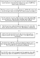
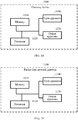
- FIG. 1 is a schematic flowchart of a data flow control method according to an embodiment of the present invention, and the data flow control method according to the embodiment of the present invention shown in FIG. 1 may include the following content:
- the first IP flow identification information may be used to identify an IP flow that is transmitted by the UE through the first access network and/or an IP flow that is transmitted by the UE through a second access network.
- the first IP flow identification information may identify, for example, various properties of the IP flow that is requested to be transmitted through the first access network by the UE and/or the IP flow that is requested to be transmitted through the second access network by the UE (such as a source address/a destination address, a type of service, and quality of service of the IP flow).
- the first access network and the second access network are access networks using different access technologies.
- one of the first access network and the second access network may be a 3GPP access network, and the other may be a non-3GPP access network (for example, a WLAN access network or another non-3GPP access network).
- the first gateway may be a serving gateway, may also be an evolved packet data gateway (ePDG, Evolved Packet Data Gateway), and certainly, may also be a gateway device implementing similar functions in another network.
- ePDG evolved packet data gateway
- Evolved Packet Data Gateway Evolved Packet Data Gateway
- the first gateway sends a second message to a PDN GW, where the second message carries second IP flow identification information, and the second IP flow identification information may be the same as the first IP flow identification information or the second IP flow identification information may be obtained based on the first IP flow identification information.
- a manner of obtaining the second IP flow identification information based on the first IP flow identification information includes: obtaining a home address or a public address included in the second IP flow identification information by converting a local address and/or a port number included in the first IP flow identification information; and/or obtaining quality of service information included in the second IP flow identification information by converting quality of service information included in the first IP flow identification information; and/or obtaining an encoding mode indication included in the second IP flow identification information by converting an encoding mode indication included in the first IP flow identification information.
- the second IP flow identification information may also be obtained by performing another form of conversion on the first IP flow identification information.
- the second IP flow identification information may also be used to identify an IP flow that is transmitted by the UE through the first access network and/or an IP flow that is transmitted by the UE through the second access network.
- the second IP flow identification information may identify, for example, various properties of the IP flow that is requested to be transmitted through the first access network and/or the IP flow that is requested to be transmitted through the second access network by the UE (such as a type of service, quality of service, and a source address/a destination address of the IP flow).
- the first gateway receives a third message sent by the packet data network gateway, where the third message carries third IP flow identification information accepted by a network.
- the third IP flow identification information accepted by the network may be regarded as IP flow identification information accepted by one network element of or jointly accepted by multiple of network elements such as the PDN GW, a policy and charging rules function (PCRF, Policy and Charging Rules Function) entity, and a subscriber server, and the like.
- the third IP flow identification information is used to identify an IP flow that is accepted by the network to be transmitted by the UE through the first access network and/or an IP flow that is accepted by the network to be transmitted by the UE through the second access network.
- the IP flow identified by the third IP flow identification information which is accepted by the network to be transmitted by the UE through the first access network and/or the IP flow identified by the third IP flow identification information, which is accepted by the network to be transmitted by the UE through the second access network, is a subset of the IP flow that is identified by the first IP flow identification information/the second IP flow identification information and transmitted by the UE through the first access network and/or the IP flow that is identified by the first IP flow identification information/the second IP flow identification information and transmitted by the UE through the second access network.
- the first gateway sends a fourth message to the UE, where the fourth message carries fourth IP flow identification information, and the fourth IP flow identification information is the same as the third IP flow identification information or the fourth IP flow identification information is obtained based on the third IP flow identification information.
- a manner of obtaining the fourth IP flow identification information based on the third IP flow identification information may include: obtaining a local address and/or a port number included in the fourth IP flow identification information by converting a home address or a public address included in the third IP flow identification information; and/or obtaining quality of service information included in the fourth IP flow identification information by converting quality of service information included in the third IP flow identification information; and/or obtaining an encoding mode indication included in the fourth IP flow identification information by converting an encoding mode indication included in the third IP flow identification information.
- the fourth IP flow identification information may also be obtained by performing another form of conversion on the third IP flow identification information.
- At least one message of the first message, the second message, the third message, and the fourth message further carries an IP flow routing address, where the IP flow routing address may include at least one of the following addresses: a local address of the UE, an address of the first gateway, and a home address of the UE.
- the IP flow routing address may be used to indicate a routing address of the IP flow that is transmitted by the UE through the first access network. If the first message does not carry the IP flow routing address, the first gateway or the PDN GW may also acquire the IP flow routing address from a network element. For example, the PDN GW may also determine the IP flow routing address according to the second message received from the first gateway, or the PDN GW uses the address of the first gateway as the IP flow routing address.
- the first message and/or the second message may further carry a packet data network (PDN, Packet Data Network) connection indication, where the PDN connection indication is used to indicate a PDN connection that has been established by the UE through the second access network, and the IP flow transmitted by the UE through the first access network uses the PDN connection (that is, the IP flow transmitted by the UE through the first access network uses the PDN connection indicated by the PDN connection indication).
- PDN connection indication may include, for example, the home address of the UE and/or a handover indication, and certainly, may also include other identification information that can indicate the PDN connection that has been established by the UE through the second access network, which are not exhaustively listed herein.
- the first message and/or the second message may further carry an IP flow mobility indication, where the IP flow mobility indication may be used to indicate that the UE requests the network to support the mobility of the IP flow thereof.
- the network supports the mobility of the IP flow thereof (or, it may be regarded that the UE requests the network to support the mobility of the IP flow thereof); in this case, the first message and/or the second message may not carry the IP flow mobility indication.
- the first IP flow identification information is IP flow identification information obtained by modifying IP flow identification information currently used by the UE, that is, the first IP flow identification information may be, for example, different from the IP flow identification information currently used by the UE.
- the first gateway receives the first message that is sent by the UE through the first access network
- the UE has established an IP flow through the first access network and an IP flow through the second access network
- the IP flow identification information currently used by the UE may identify the IP flow that is transmitted by the UE through the first access network and/or the IP flow that is transmitted by the UE through the second access network.
- the IP flow that is allowed by the network to be transmitted by the UE through the first access network and/or the IP flow that is allowed by the network to be transmitted by the UE through the second access network includes: the IP flow that is identified by the IP flow identification information currently used by the UE and transmitted by the UE through the first access network and/or the IP flow that is identified by the IP flow identification information currently used by the UE and transmitted by the UE through the second access network.
- the first gateway and the UE may transfer the first IP flow identification information and the fourth IP flow identification information based on multiple possible procedures.
- the first gateway and the UE may transfer the first IP flow identification information and the fourth IP flow identification information based on an Internet Key Exchange (IKEv2, Internet Key Exchange version 2) protocol message or a protocol message of another type.
- IKEv2 Internet Key Exchange
- the first message may be, for example, an IKEv2 authentication request message
- the fourth message may be, for example, an IKEv2 authentication response message.
- the first message is an IKEv2 informational request message
- the fourth message may be an IKEv2 informational response message.
- the first message may also be another IKEv2 protocol message or another protocol message that can be sent by the UE to the first gateway
- the fourth message may also be another IKEv2 protocol message or another protocol message that can be sent by the first gateway to the UE. Examples are not exhaustively listed herein.
- the first IP flow identification information is carried in a traffic selector or another information element of the first message. If the fourth message is the IKEv2 authentication response message or the IKEv2 informational response message (or another IKEv2 protocol message), the fourth IP flow identification information is carried in a traffic selector or another information element of the fourth message.
- the method may further include that: the first gateway receives a fifth message (a message type of the fifth message is the same as or different from a message type of the first message) sent by the UE through the first access network, where the fifth message may carry fifth IP flow identification information, and the fifth IP flow identification information is used to identify the IP flow that is transmitted by the UE through the first access network and/or the IP flow that is transmitted by the UE through the second access network; and the first gateway may send an authentication request message to an authentication server, and may negotiate with the UE according to an operator policy returned by the authentication server and/or subscription data of the UE returned by the authentication server, to obtain the first IP flow identification information.
- a message type of the fifth message is the same as or different from a message type of the first message
- the fifth message may carry fifth IP flow identification information
- the fifth IP flow identification information is used to identify the IP flow that is transmitted by the UE through the first access network and/or the IP flow that is transmitted by the UE through the second access network
- the first gateway may send an
- the first gateway and the PDN GW may transfer the second IP flow identification information and the third IP flow identification information based on multiple possible procedures.
- the second message may be a Proxy Mobile IPv6 (PMIPv6, Proxy Mobile IPv6) Proxy Binding Update message
- the third message may be a PMIPv6 Proxy Binding ACK message.
- the second message may also be a General Packet Radio Service Tunneling Protocol (GTP, GPRS Tunnelling Protocol) Create Session Request message
- the third message may be a GTP Create Session Response message.
- the second message may be a GTP Bearer Resource Command message
- the third message may be a GTP Update Bearer Request message.
- the second message may be a GTP Modify Bearer Request message
- the third message may be a GTP Modify Bearer Response message.
- the first gateway may also interact with the PDN GW based on other procedures, which are not exhaustively listed herein.
- a first gateway receives a first message that is sent by a UE through a first access network and carries first IP flow identification information, where the first IP flow identification information is used to identify an IP flow that is transmitted by the UE through the first access network and/or an IP flow that is transmitted by the UE through a second access network, and the first access network and the second access network are access networks using different access technologies; and the first gateway sends a second message carrying second IP flow identification information to a PDN GW, where the second IP flow identification information is the same as the first IP flow identification information, or the second IP flow identification information may be obtained based on the first IP flow identification information.
- the UE interacts with the PDN GW by using the first gateway (such as an ePDG or a serving gateway) as a proxy. Therefore, without function enhancement to support protocols such as DSMIPv6, the UE can flexibly request, by using the first gateway as a proxy, the PDN GW to allow the UE to transmit an IP flow through the first access network and/or an IP flow through the second access network, further implementing IP flow mobility between access networks using different access technologies.
- the present invention seeks to enable the UE to perform multi-access IP flow transmission through the access networks using different access technologies, and implement seamless switching of the IP flow between the access networks using different access technologies (for example, a WLAN access network and a 3GPP access network). In this manner, a requirement on a UE capability in implementation of the IP flow mobility is lowered, and implementation costs of the solution are reduced, making it more feasible for a system (including a network and a terminal) to support the feature of IP flow mobility.
- the data flow control method may include: receiving, by a PDN GW, a second message sent by a first gateway, where the second message carries second IP flow identification information, and the second IP flow identification information is used to identify an IP flow that is transmitted by a UE through a first access network and/or an IP flow that is transmitted by a UE through a second access network, where the first access network and the second access network are access networks using different access technologies; establishing, by the PDN GW, a binding relationship between an IP flow routing address and third IP flow identification information or the second IP flow identification information, where the third IP flow identification information is IP flow identification information accepted by a network, the third IP flow identification information is used to identify an IP flow that is accepted by the network to be transmitted by the UE through the first access network and/or an IP flow that is accepted by the network to be transmitted by the UE through the second access network, and the IP flow routing address includes at least one of the following addresses: a local address of the UE,
- FIG. 2 is a schematic flowchart of another data flow control method according to an embodiment of the present invention, and the another data flow control method according to the embodiment of the present invention shown in FIG. 2 may include the following content:
- the first gateway may send a second message to the PDN GW.
- the first message may carry first IP flow identification information, and the first IP flow identification information is used to identify an IP flow that is transmitted by the UE through the first access network and/or an IP flow that is transmitted by the UE through the second access network.
- the first gateway sends the second message carrying the second IP flow identification information to the PDN GW, where the second IP flow identification information is the same as the first IP flow identification information, or the second IP flow identification information is obtained based on the first IP flow identification information.
- the PDN GW establishes a binding relationship between an IP flow routing address and third IP flow identification information or the second IP flow identification information.
- the third IP flow identification information is IP flow identification information accepted by a network, and the third IP flow identification information is used to identify an IP flow that is accepted by the network to be transmitted by the UE through the first access network and/or an IP flow that is accepted by the network to br transmitted by the UE through the second access network.
- the IP flow routing address includes at least one of the following address: a local address of the UE, an address of a first gateway, and a home address of the UE.
- the third IP flow identification information accepted by the network may be regarded as IP flow identification information accepted by one network element of or jointly accepted by multiple of network elements such as the PDN GW, a policy and charging rules function (PCRF, Policy and Charging Rules Function) entity, and a subscriber server.
- PCRF policy and charging rules function
- subscriber server a subscriber server
- the IP flow identified by the third IP flow identification information which is accepted by the network to be transmitted by the UE through the first access network and/or the IP flow identified by the third IP flow identification information, which is accepted by the network to be transmitted by the UE through the second access network, is a subset of the IP flow that is identified by the first IP flow identification information/the second IP flow identification information and transmitted by the UE through the first access network and/or the IP flow that is identified by the first IP flow identification information/the second IP flow identification information and transmitted by the UE through the second access network.
- the PDN GW sends a third message to the first gateway, where the third message carries third IP flow identification information.
- the PDN GW may further associate an IP flow established by the UE through the first access network with a PDN connection or an IP flow established by the UE through the second access network.
- IP flow transmitted by the UE through the first access network uses the PDN connection established by the UE through the second access network.
- the PDN GW may further send the second IP flow identification information and the IP flow routing address to the PCRF entity; the PDN GW receives sixth IP flow identification information returned by the PCRF entity; and the PDN GW determines the third IP flow identification information according to the sixth IP flow identification information.
- the first gateway and the PDN GW may transfer the second IP flow identification information and the third IP flow identification information based on multiple possible procedures.
- the second message may be a PMIPv6 Proxy Binding Update message
- the third message may be a PMIPv6 Proxy Binding ACK message.
- the second message may be a GTP Create Session Request message
- the third message may be a GTP Create Session Response message.
- the second message may be a GTP Bearer Resource Command message
- the third message may be a GTP Update Bearer Request message.
- the second message may be a GTP Modify Bearer Request message
- the third message may be a GTP Modify Bearer Response message.
- the first gateway may also interact with the PDN GW based on other procedures, which are not exhaustively listed herein.
- a PDN GW receives a second message sent by a first gateway, where the second message carries second IP flow identification information, and the second IP flow identification information is used to identify an IP flow that is transmitted by a UE through a first access network and/or an IP flow that is transmitted by the UE through a second access network, where the first access network and the second access network are access networks using different access technologies; the PDN GW establishes a binding relationship between an IP flow routing address and third IP flow identification information or the second IP flow identification information; and the PDN GW sends a third message carrying the third IP flow identification information to the first gateway.
- the UE interacts with the PDN GW by using the first gateway (such as an ePDG or a serving gateway) as a proxy. Therefore, without function enhancement to support protocols such as DSMIPv6, the UE can flexibly request, by using the first gateway as a proxy, the PDN GW to allow the UE to transmit an IP flow through the first access network and/or an IP flow through the second access network, further implementing IP flow mobility between access networks using different access technologies.
- the present invention seeks to enable the UE to perform multi-access IP flow transmission through the access networks using different access technologies, and implement seamless switching of the IP flow between the access networks using different access technologies (for example, a WLAN access network and a 3GPP access network). In this manner, a requirement on a UE capability in implementation of the IP flow mobility is lowered, and implementation costs of the solution are reduced, making it more feasible for a system (including a network and a terminal) to support the feature of IP flow mobility.
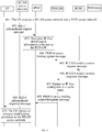
- FIG. 3 is a schematic flowchart of another data flow control method according to an embodiment of the present invention.
- FIG. 3 shows a solution to establishing an IP flow by WLAN access and an IP flow by 3GPP access based on the PMIPv6 protocol.
- a data flow control method may include the following content:
- the IKE_AUTH request message may carry the following information:
- the ePDG initiates UE authentication to a 3GPP AAA Server.
- An authentication request message may carry a user identity, an APN, and other information, so as to request the 3GPP network to authenticate the UE; and may also carry an IP flow mobility indication, so as to request the network to determine whether to allow the UE to use the feature of IP flow mobility.
- the 3GPP AAA Server may interact with a home subscriber server (HSS, Home Subscriber Server) of the UE to acquire information such as subscription data of the UE and an operator policy.
- the 3GPP AAA Server may send the obtained information such as the subscription data and the operator policy to the ePDG.
- the subscription data of the UE and the operator policy may include at least one piece of the following information: an indication of whether the IP flow mobility is supported, and an address, a port number, a protocol type, QoS, a service/application type, a media type, an encoding mode, and the like, of the IP flow that is allowed to be transmitted through the WLAN or preferably transmitted through the WLAN.
- the ePDG may determine, according to the 3GPP subscription data of the UE and/or the operator policy, the IP flow identification information requested by the UE, and if the IP flow identification information requested by the UE does not conform to corresponding information in the 3GPP subscription data of the UE and/or the operator policy, the ePDG may further send, to the UE, IP flow identification information that can be accepted by the 3GPP network.
- the UE may modify the previous IP flow identification information according to the IP flow identification information accepted by the 3GPP network, and may send, to the ePDG by using an Internet Key Exchange protocol authentication request message IKE_AUTH Request or an Internet Key Exchange protocol informational request message IKEv2 Informational Request or another IKEv2 message, new IP flow identification information obtained after the modification.
- the ePDG determines, according to the IP flow identification information requested by the UE, IP flow identification information, namely, an IP flow routing filter (Routing filter), to be sent to the PDN GW, including: if the IP flow identification information requested by the UE includes a local address (local address) and/or a port number, the ePDG converts the local address and/or the port number into a home IP address (home address) or a public address (public IP address), and may perform, for example, a QoS mapping, an encoding mode mapping, or conversion.
- IP flow identification information namely, an IP flow routing filter (Routing filter)
- Routing filter IP flow routing filter
- the ePDG may select a PDN GW based on an access point name (APN, Access Point Name), and send a PMIPv6 proxy binding update (PBU, Proxy Binding Update) message to the selected PDN GW.
- APN Access Point Name
- PBU Proxy Binding Update
- the PMIPv6 PBU message may carry information such as an IP flow Routing filter, a routing address Routing Address, a PDN connection indication, an IP flow mobility indication and a mobile node network access identifier (MN NAI, Mobile Node Network Access Identifier, namely, user identity), an APN and/or a radio access technology (RAT, Radio Access Technology) type.
- MN NAI Mobile Node Network Access Identifier
- RAT Radio Access Technology
- the IP flow Routing filter and the routing address (Routing Address) associated with the IP flow Routing filter together form an IP flow routing rule, that is, a routing rule describes an association relationship between the routing filter and the routing address, and is used to indicate that an IP flow satisfying a certain condition, namely, the routing filter, is transmitted by using a specific address (namely, the routing address).
- the IP flow routing address carried in the PMIPv6 PBU message may be, for example, an address of the ePDG or a local address of the UE (namely, an address allocated by the WLAN access network to the UE), which indicates that the IP flow (namely, an IP packet data packet) satisfying the identification of the IP flow Routing filter is transmitted through the WLAN access network.
- the address of the ePDG may be a public IP address of the ePDG, or a link-local address (link-local address) allocated by the PDN GW.
- the link-local address carried in the PMIPv6 PBU message may be all 0s (that is, all bytes are 0), so as to give an instruction of requesting the PDN GW to allocate, to the ePDG, the link-local address, namely, an address of an access link shared by the ePDG and the UE.
- the RAT Type is WLAN access.
- the ePDG If the ePDG supports establishment of multiple PDN connections for one APN, the ePDG further generates one PDN connection identity (PDN Connection identity) and adds the PDN connection identity to the PMIPv6 PBU message.
- the ePDG may further generate a flow identity (Flow ID) according to security association SA (Security Association) information such as a differentiated services code point (DSCP, Diffserv Code Point), and add the flow identity to the PMIPv6 PBU message.
- SA Security Association
- the PDN GW may initiate an IP-connection access network (IP-CAN) session modification request message to a PCRF entity, where the IP-CAN session modification request message may carry the IP flow routing rule.
- IP-CAN IP-connection access network
- the PCRF may send an IP-CAN session modification response message to the PDN GW.
- the IP-CAN session modification response message may carry the IP flow routing rule acknowledged by the PCRF, where the PCRF may modify a downlink IP flow routing rule and/or an uplink IP flow routing rule.
- the PCRF may further update, according to the IP flow routing rule, an IP flow routing rule stored in the PCRF.
- the PDN GW generates a binding cache entry (binding cache entry) for the UE based on the received PMIPv6 PBU message.
- the PDN GW allocates, to the UE according to the PDN connection indication, an IP address identical to that of the PDN Connection established by the UE in the 3GPP access network, that is, the home address allocated by the PDN GW to the UE is the same as the IP address of the PDN Connection that is established by the UE in the 3GPP access network and indicated by the PDN Connection indication.
- the PDN GW may associate the binding cache entry, that is, a binding cache entry of the PDN Connection or the IP flow established through the WLAN, with a binding cache entry of the corresponding PDN Connection or IP flow established through the 3GPP access network; or the PDN GW combines the foregoing two binding cache entries into one binding cache entry, where the foregoing two binding cache entries are distinguished from each other by using different access modes RAT Types and/or routing addresses, so as to perform charging or subsequent operations such as bearer/IP flow modification.
- the PDN GW may also associate the foregoing information in another manner.
- the PDN GW reports a PDN GW identity and the corresponding RAT Type (which is the WLAN access here) to the 3GPP AAA Server, and the 3GPP AAA Server reports the PDN GW identity, the RAT Type, the corresponding APN, and identification information of a PLMN to an HSS.
- the PDN GW sends a PMIPv6 proxy binding acknowledgment (PBA, Proxy Binding Acknowledgment) message to the ePDG, where the message carries information such as IP flow identification information (namely, an IP flow routing filter) accepted by the network, the routing address, the MN NAI, the APN, and an IP address allocated to the UE (namely, the home address of the UE).
- PBA Proxy Binding Acknowledgment
- the IP flow routing address carried in the PMIPv6 PBA message may be, for example, an address of the ePDG or a local address of the UE (namely, an address allocated by the WLAN access network to the UE), which indicates that the IP flow (namely, an IP packet data packet) satisfying the identification of the IP flow Routing filter is transmitted through the WLAN access network.
- the address of the ePDG may be a public IP address of the ePDG, or a link-local address allocated by the PDN GW (namely, an address of an access link shared by the ePDG and the UE).
- the PMIPv6 PBU message carries the PDN connection identity and the PDN GW supports establishment of multiple PDN connections for the APN
- the PMIPv6 PBA message also includes the PDN connection identity.
- the ePDG indicates authentication completion to the UE, and the UE completes the authentication on the ePDG.
- An IPSec tunnel is successfully established.
- the ePDG determines, according to the routing filter Routing filter in the PBA message, a Traffic Selector to be sent to the UE.
- the ePDG sends an IKE_AUTH response message to the UE, where the message carries information such as the Traffic Selector, the IP address allocated by the PDN GW to the UE, namely, the home address of the UE, and the APN. If the PBA message carries the PDN connection identity, the IKE_AUTH response message further includes the PDN connection identity.
- uplink packet data of the UE which conforms to an uplink Traffic Selector, namely, the uplink routing rule, is sent to the ePDG through the IPSec tunnel, and is then sent by the ePDG to the PDN GW through the PMIPv6 tunnel.
- the PDN GW sends downlink packet data of the UE to the ePDG through the PMIPv6 tunnel according to the downlink routing rule in the binding cache entry, and then the ePDG sends the downlink packet data to the UE through the IPSec tunnel.
- the PCRF or the PDN GW may initiate release of 3GPP resources, to release corresponding bearer resources in the 3GPP network.
- an ePDG receives a message that is sent by a UE through a WLAN access network and carries first IP flow identification information, where the first IP flow identification information is used to identify an IP flow transmitted by the UE through the WLAN; and the ePDG sends a message carrying second IP flow identification information to a PDN GW, where the second IP flow identification information is the same as the first IP flow identification information, or the second IP flow identification information may be obtained based on the first IP flow identification information.
- the UE interacts with the PDN GW by using the ePDG as a proxy.
- the UE can flexibly request, by using the ePDG as a proxy, the PDN GW to allow the UE to transmit an IP flow through a WLAN access network and/or an IP flow through a 3GPP access network, further implementing IP flow mobility between access networks using different access technologies.
- the present invention seeks to enable the UE to perform multi-access IP flow transmission through the access networks using different access technologies, and implement seamless switching of the IP flow between the WLAN access network and the 3GPP access network. In this manner, a requirement on a UE capability in implementation of the IP flow mobility is lowered, and implementation costs of the solution are reduced, making it more feasible for a system (including a network and a terminal) to support the feature of IP flow mobility.
- FIG. 4 is a schematic flowchart of another data flow control method according to an embodiment of the present invention.
- FIG. 4 shows a solution of moving an IP flow between a WLAN and a 3GPP based on PMIPv6.
- the data flow control method shown in FIG. 4 may include the following content:
- the IKEv2 informational request message may include:
- the modification on the current IP flow identification information includes: adding information, and modifying or deleting existing information, for example, modifying one or a combination of the filtering rules such as a source address, a source port number, a destination address, a destination port number, a protocol type, QoS related information, a service/application type (application type), a media type, and an encoding mode of the IP flow.
- the UE sends a request to the 3GPP network by modifying the current IP flow identification information, to determine which new IP flows are to be transmitted through the WLAN access network, or which IP flows are no longer transmitted through the WLAN access network, or the like.
- the IKEv2 informational request message may further carry a PDN connection identity.
- the ePDG may determine, according to 3GPP subscription data of the UE and/or an operator policy, the IP flow identification information requested by the UE, and if the IP flow identification information requested by the UE does not conform to corresponding information in the 3GPP subscription data of the UE and/or the operator policy, the ePDG may further send, to the UE, IP flow identification information that can be accepted by the 3GPP network.
- the UE may modify the previous IP flow identification information according to the IP flow identification information accepted by the 3GPP network, and may send, to the ePDG by using an IKE_AUTH request, or an IKEv2 Informational request or another IKEv2 message, new IP flow identification information obtained after the modification.
- the ePDG determines, according to the IP flow identification information requested by the UE, IP flow identification information, namely, an IP flow routing filter Routing filter, to be sent to a PDN GW.
- the ePDG may convert the local address and/or the port number into a home IP address (home address) or a public address (public IP address), and perform a QoS mapping, an encoding mode mapping, or conversion.
- the ePDG sends a PMIPv6 PBU message to the PDN GW.
- the PMIPv6 PBU message may carry information such as a routing filter, an IP flow routing address, a PDN connection indication, an IP flow mobility indication, and a mobile node network access identifier MN NAI, an APN, and a radio access technology type.
- the routing filter and the routing address associated with the routing filter together form a routing rule, that is, a routing rule describes an association relationship between the routing filter and the routing address, and is used to indicate that an IP flow satisfying a certain condition, namely, the routing filter, is transmitted by using a specific address, namely, the routing address.
- the routing address in the PMIPv6 PBU message is an address of the ePDG, or a local address of the UE, namely, an address allocated by the WLAN access network to the UE, which indicates that an IP flow, namely, an IP packet data packet, satisfying the routing filter in the PMIPv6 PBU message is transmitted through the WLAN access network.
- the address of the ePDG may be a public IP address of the ePDG, or a link-local address (link-local address) allocated by the PDN GW.
- the RAT Type is WLAN access.
- the ePDG may add, according to the PDN connection identity included in the IKEv2 INFORMATIONAL Request message, the PDN connection identity to the PBU message; or if the IKEv2 INFORMATIONAL Request message does not carry the PDN connection identity, the ePDG may insert the corresponding PDN connection identity in the PBU message according to a mapping relationship between a security association identity and a PDN connection.
- the ePDG may further generate a flow identity Flow ID according to the security association identity such as a differentiated services code point (DSCP, Diffserv Code Point), and add the flow ID to the PMIPv6 PBU message.
- DSCP differentiated services code point
- Diffserv Code Point Diffserv Code Point
- the PDN GW may initiate an IP-connection access network (IP-CAN) session modification request to a PCRF, where the IP-CAN session modification request message carries the IP flow routing rule.
- IP-CAN IP-connection access network
- the PCRF may send an IP-CAN session modification response message to the PDN GW.
- the IP-CAN session modification response message may carry the IP flow routing rule acknowledged by the PCRF, where the PCRF may modify a downlink routing rule and/or an uplink routing rule.
- the PCRF may further update, according to the IP flow routing rule, an IP flow routing rule stored in the PCRF.
- the PDN GW updates an IP flow routing rule in a binding cache entry (binding cache entry) of the UE based on the received PMIPv6 PBU message.
- the PDN GW sends a PMIPv6 proxy binding acknowledgment (PBA, Proxy Binding Acknowledgment) message to the ePDG, where the message carries information such as IP flow identification information accepted by the network, namely, the IP flow routing filter, a routing address, an IP address allocated to the UE (namely, a home address of the UE), an MN NAI, and an APN.
- the routing address in the PMIPv6 PBA message is an address of the ePDG, or a local address of the UE, namely, an address allocated by the WLAN access network to the UE, which indicates that an IP flow, namely, an IP packet data packet, satisfying the routing filter in the PMIPv6 PBA message is transmitted through the WLAN access network.
- the address of the ePDG may be a public IP address of the ePDG, or a link-local address allocated by the PDN GW, namely, an address of an access link shared by the ePDG and the UE.
- the PBA message further includes the PDN connection identity.
- the ePDG determines, according to the routing filter Routing filter in the PBA message, a Traffic Selector to be sent to the UE.
- the ePDG sends an IKEv2 informational response (INFORMATIONAL Response) message to the UE, where the message may carry information such as the Traffic Selector, the IP address allocated by the PDN GW to the UE (namely, the home address of the UE), and the APN.
- IKEv2 informational response IKEv2 informational response (INFORMATIONAL Response) message
- the message may carry information such as the Traffic Selector, the IP address allocated by the PDN GW to the UE (namely, the home address of the UE), and the APN.
- the IKE_AUTH response message further includes the PDN connection identity.
- the UE may initiate a resource modification procedure in the WLAN access network according to the received Traffic Selector, namely, the IP flow routing rule accepted by the network.
- the PCRF or the PDN GW initiates and performs a procedure of releasing or allocating corresponding 3GPP resources, to release or establish corresponding bearer resources in the 3GPP network.
- the PDN GW may determine, according to an association relationship between the PDN Connections or the IP flows separately established through the WLAN access network and the 3GPP access network, to initiate the procedure of releasing or allocating corresponding 3GPP resources.
- an ePDG receives a message that is sent by a UE through a WLAN access network and carries first IP flow identification information, where the first IP flow identification information is used to identify an IP flow transmitted by the UE through the WLAN; and the ePDG sends a message carrying second IP flow identification information to a PDN GW, where the second IP flow identification information is the same as the first IP flow identification information, or the second IP flow identification information may be obtained based on the first IP flow identification information.
- the UE interacts with the PDN GW by using the ePDG as a proxy.
- the UE can flexibly request, by using the ePDG as a proxy, the PDN GW to allow the UE to transmit an IP flow through a WLAN access network and/or an IP flow through a 3GPP access network, further implementing IP flow mobility between access networks using different access technologies.
- the present invention seeks to enable the UE to perform multi-access IP flow transmission through the access networks using different access technologies, and implement seamless switching of the IP flow between the WLAN access network and the 3GPP access network. In this manner, a requirement on a UE capability in implementation of the IP flow mobility is lowered, and implementation costs of the solution are reduced, making it more feasible for a system (including a network and a terminal) to support the feature of IP flow mobility.
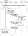
- FIG. 5 is a schematic flowchart of another data flow control method according to an embodiment of the present invention.
- FIG. 5 shows a solution to establishing an IP flow by WLAN access and an IP flow by 3GPP access based on the GTP protocol.
- the data flow control method shown in FIG. 5 may include the following content:
- the ePDG selects a PDN GW based on an access point name APN, and sends a GTP create session request (Create Session Request) message to the selected PDN GW.
- GTP create session request Create Session Request
- the GTP Create Session Request message carries information such as a routing filter Routing filter, a routing address Routing Address, a PDN connection indication, an IP flow mobility indication, an international mobile subscriber identity (IMSI, International Mobile Subscriber Identification Number), an APN, and a radio access technology RAT Type.
- the routing filter Routing filter may be carried in a traffic flow template TFT (Traffic Flow Template) of the GTP Create Session Request message.
- TFT Traffic Flow Template
- the routing filter and the routing address associated with the routing filter together form a routing rule, that is, a routing rule describes an association relationship between the routing filter and the routing address, and is used to indicate that an IP flow satisfying a certain condition, namely, the routing filter, is transmitted by using a specific address, namely, the routing address.
- the routing address Routing Address is an address of the ePDG, or a local address of the UE, namely, an address allocated by the WLAN access network to the UE, which indicates that an IP flow, namely, an IP packet data packet, satisfying the routing filter Routing filter in the GTP Create Session Request message is transmitted through the WLAN access network.
- the RAT Type is WLAN access.
- the ePDG may generate an EPS bearer identity EPS bearer ID, and adds it to the Create Session Request message.
- the PDN GW may initiate an IP-connection access network (IP-CAN) session modification request to a PCRF, where the IP-CAN session modification request message carries the IP flow routing rule.
- IP-CAN IP-connection access network
- the PCRF may send an IP-CAN session modification response message to the PDN GW.
- the IP-CAN session modification response message may carry the IP flow routing rule acknowledged by the PCRF, where the PCRF may modify a downlink routing rule and/or an uplink routing rule.
- the PCRF may further update, according to the IP flow routing rule, an IP flow routing rule stored in the PCRF.
- the PDN GW generates an entry in an EPS bearer context table EPS bearer context table based on the received GTP session create request message.
- the PDN GW may allocate, to the UE according to the PDN connection indication, an IP address identical to that of the PDN Connection established by the UE in the 3GPP access network; in addition, the PDN GW may associate the entry, namely, an entry of the PDN Connection or the IP flow established by the UE through the WLAN, with an entry of a corresponding PDN Connection or IP flow established through the 3GPP access network; or the PDN GW combines the foregoing two entries into a same PDN Connection or IP flow entry, where the foregoing two entries are distinguished from each other by using different access modes RAT Types and/or routing addresses, so as to perform charging or subsequent operations such as bearer/IP flow modification.
- the PDN GW reports a PDN GW identity and the corresponding RAT Type (which is the WLAN access here) to the 3GPP AAA Server, and the 3GPP AAA Server reports the PDN GW identity, the RAT Type, the corresponding APN, and identification information of a PLMN to an HSS.
- the PDN GW sends a GTP Create Session Response message Create Session Response to the ePDG, where the message carries information such as IP flow identification information accepted by the network, namely, the IP flow routing filter Routing filter, the routing address Routing address, the IP address allocated to the UE, the IMSI, the APN, and the EPS bearer identity.
- the routing filter Routing filter may be carried in a traffic flow template TFT (Traffic Flow Template).
- the routing address Routing Address is an address of the ePDG, or a local address of the UE, namely, an address allocated by the WLAN access network to the UE, which indicates that an IP flow, namely, an IP packet data packet, satisfying the routing filter Routing filter in the GTP Create Session Response message, is transmitted through the WLAN access network.
- the ePDG indicates authentication completion to the UE, and the UE completes the authentication on the ePDG.
- An IPSec tunnel is successfully established.
- the ePDG determines, according to the routing filter Routing filter in the Create Session Response message Create Session Response, a Traffic Selector to be sent to the UE.
- the ePDG sends an IKE_AUTH response message to the UE, where the message carries information such as the Traffic Selector, the IP address allocated by the PDN GW to the UE, and the APN.
- Uplink packet data of the UE which conforms to an uplink Traffic Selector, namely, the uplink routing rule, is sent to the ePDG through the IPSec tunnel, and is then sent by the ePDG to the PDN GW through a GTP tunnel.
- the PDN GW sends downlink packet data of the UE to the ePDG through the GTP tunnel according to the downlink routing rule in the binding cache entry, and then the ePDG sends the downlink packet data to the UE through the IPSec tunnel.
- the PCRF or the PDN GW may initiate release of 3GPP resources, to release corresponding bearer resources in the 3GPP network.
- an ePDG receives a message that is sent by a UE through a WLAN access network and carries first IP flow identification information, where the first IP flow identification information is used to identify an IP flow transmitted by the UE through the WLAN; and the ePDG sends a message carrying second IP flow identification information to a PDN GW, where the second IP flow identification information is the same as the first IP flow identification information, or the second IP flow identification information may be obtained based on the first IP flow identification information.
- the UE interacts with the PDN GW by using the ePDG as a proxy.
- the UE can flexibly request, by using the ePDG as a proxy, the PDN GW to allow the UE to transmit an IP flow through a WLAN access network and/or an IP flow through a 3GPP access network, further implementing IP flow mobility between access networks using different access technologies.
- the present invention seeks to enable the UE to perform multi-access IP flow transmission through the access networks using different access technologies, and implement seamless switching of the IP flow between the WLAN access network and the 3GPP access network. In this manner, a requirement on a UE capability in implementation of the IP flow mobility is lowered, and implementation costs of the solution are reduced, making it more feasible for a system (including a network and a terminal) to support the feature of IP flow mobility.
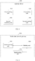
- FIG. 6 is a schematic flowchart of another data flow control method according to an embodiment of the present invention.
- FIG. 6 shows a solution to moving an IP flow between WLAN access and 3GPP access based on the GTP protocol.
- the data flow control method shown in FIG. 6 may include the following content:
- the ePDG sends a GTP Bearer Resource Command message Bearer Resource Command to the PDN GW.
- the GTP Bearer Resource Command message may carry:
- Step 605 to step 606 are the same as step 405 to step 406 in the embodiment shown in FIG. 4 .
- the PDN GW updates a routing rule in a corresponding entry of an EPS bearer context table EPS bearer context table of the UE based on the received bearer resource command (Bearer Resource Command) message.
- Bearer Resource Command Bearer Resource Command
- the PDN GW sends a GTP update bearer request (Update Bearer Request) message to the ePDG, where the message carries IP flow identification information accepted by the network, namely, information such as a routing filter Routing filter, a routing address Routing address, and an EPS Bearer ID of the IP flow.
- the routing filter Routing filter may be carried in a traffic flow template TFT (Traffic Flow Template).
- TFT Traffic Flow Template
- the routing address Routing Address is an address of the ePDG, or a local address of the UE, namely, an address allocated by the WLAN access network to the UE, which indicates that an IP flow, namely, an IP packet data packet, satisfying the routing filter Routing filter in the GTP Update Bearer Request message is transmitted through the WLAN access network.
- the ePDG sends a GTP update bearer response message Update Bearer Response to the PDN GW, which indicates that modified IP flow identification information is received.
- the ePDG determines, according to the routing filter Routing filter in the Update Bearer Request message Update Bearer Request, a Traffic Selector to be sent to the UE.
- the ePDG sends an IKE_AUTH response message to the UE, where the message carries information such as the Traffic Selector and the APN.
- the UE may initiate a resource modification procedure in the WLAN access network according to the received Traffic Selector, namely, the IP flow identification information accepted by the network.
- the PCRF or the PDN GW initiates and performs a procedure of releasing or allocating corresponding 3GPP resources, to release or establish corresponding bearer resources in the 3GPP network.
- the PDN GW may determine, according to an association relationship between the PDN Connections of the IP flows or the IP flows separately established through the WLAN access network and the 3GPP access network, to initiate the procedure of releasing or allocating corresponding 3GPP resources.
- an ePDG receives a message that is sent by a UE through a WLAN access network and carries first IP flow identification information, where the first IP flow identification information is used to identify an IP flow transmitted by the UE through the WLAN; and the ePDG sends a message carrying second IP flow identification information to a PDN GW, where the second IP flow identification information is the same as the first IP flow identification information, or the second IP flow identification information may be obtained based on the first IP flow identification information.
- the UE interacts with the PDN GW by using the ePDG as a proxy.
- the UE can flexibly request, by using the ePDG as a proxy, the PDN GW to allow the UE to transmit an IP flow through a WLAN access network and/or an IP flow through a 3GPP access network, further implementing IP flow mobility between access networks using different access technologies.
- the present invention seeks to enable the UE to perform multi-access IP flow transmission through the access networks using different access technologies, and implement seamless switching of the IP flow between the WLAN access network and the 3GPP access network. In this manner, a requirement on a UE capability in implementation of the IP flow mobility is lowered, and implementation costs of the solution are reduced, making it more feasible for a system (including a network and a terminal) to support the feature of IP flow mobility.
- FIG. 7 is a schematic flowchart of another data flow control method according to an embodiment of the present invention.
- FIG. 7 shows another solution to moving an IP flow between WLAN access and 3GPP access based on the GTP protocol.
- the data flow control method shown in FIG. 7 may include the following content:
- Step 701 to step 703 are the same as step 601 to step 603 in the embodiment shown in FIG. 6 .
- the ePDG sends a GTP Modify Bearer Request message Modify Bearer Request to the PDN GW.
- the GTP Modify Bearer Request message may carry information such as a routing filter Routing filter, a routing address Routing Address, an IMSI, an APN, an RAT Type, and an EPS Bearer ID.
- the routing filter Routing filter may be carried in a traffic flow template TFT (Traffic Flow Template).
- TFT Traffic Flow Template
- the routing filter and the routing address associated with the routing filter together form a routing rule, that is, a routing rule describes an association relationship between the routing filter and the routing address, and is used to indicate that an IP flow satisfying a certain condition, namely, the routing filter, is transmitted by using a specific address, namely, the routing address.
- the routing address Routing Address is an address of the ePDG, or a local address of the UE, namely, an address allocated by the WLAN access network to the UE, which indicates that an IP flow, namely, an IP packet data packet, satisfying the routing filter Routing filter in the GTP Modify Bearer Request message is transmitted through the WLAN access network.
- the ePDG may insert a corresponding default EPS bearer identity default EPS bearer ID into the Modify Bearer Request message according to a mapping relationship between a security association SA (Security Association) and a PDN connection; the ePDG may also insert an EPS bearer ID of a dedicated bearer into the Modify Bearer Request message according to the SA information such as a differentiated services code point DSCP (Diffserv Code Point).
- SA Security Association
- DSCP Different Service Code Point
- Step 705 to step 706 are the same as step 605 to step 606 in the embodiment shown in FIG. 6 .
- the PDN GW updates an IP flow routing rule in a corresponding entry of an EPS bearer context table EPS bearer context table of the UE based on the received GTP Modify Bearer Request message Modify Bearer Request.
- the PDN GW sends a GTP Modify Bearer Response message Modify Bearer Response to the ePDG, where the message carries IP flow identification information accepted by the network, namely, information such as a routing filter Routing filter, a routing address Routing address, and an EPS Bearer ID of the IP flow.
- the routing filter Routing filter may be carried in a traffic flow template TFT (Traffic Flow Template).
- TFT Traffic Flow Template
- the routing address Routing Address is an address of the ePDG, or a local address of the UE, namely, an address allocated by the WLAN access network to the UE, which indicates that an IP flow, namely, an IP packet data packet, satisfying the routing filter Routing filter in the GTP Modify Bearer Response message is transmitted through the WLAN access network.
- the ePDG determines, according to the routing filter Routing filter in the Modify Bearer Response message Modify Bearer Response, a Traffic Selector to be sent to the UE.
- the ePDG sends an IKE_AUTH response message to the UE, where the message carries information such as the Traffic Selector and the APN.
- the UE may initiate a resource modification procedure in the WLAN access network according to the received Traffic Selector, namely, the IP flow identification information accepted by the network.
- the PCRF or the PDN GW initiates and performs a procedure of releasing or allocating corresponding 3GPP resources, to release or establish corresponding bearer resources in the 3GPP network.
- the PDN GW may determine, according to an association relationship between the PDN Connections of the IP flows or the IP flows separately established through the WLAN access network and the 3GPP access network, to initiate the procedure of releasing or allocating corresponding 3GPP resources.
- an ePDG receives a message that is sent by a UE through a WLAN access network and carries first IP flow identification information, where the first IP flow identification information is used to identify an IP flow transmitted through the WLAN by the UE; and the ePDG sends a message carrying second IP flow identification information to a PDN GW, where the second IP flow identification information is the same as the first IP flow identification information, or the second IP flow identification information may be obtained based on the first IP flow identification information.
- the UE interacts with the PDN GW by using the ePDG as a proxy.
- the UE can flexibly request, by using the ePDG as a proxy, the PDN GW to allow the UE to transmit an IP flow through a WLAN access network and/or an IP flow through a 3GPP access network, further implementing IP flow mobility between access networks using different access technologies.
- the present invention seeks to enable the UE to perform multi-access IP flow transmission through the access networks using different access technologies, and implement switching of the IP flow between the WLAN access network and the 3GPP access network. In this manner, a requirement on a UE capability in implementation of the IP flow mobility is lowered, and implementation costs of the solution are reduced, making it more feasible for a system (including a network and a terminal) to support the feature of IP flow mobility.
- An embodiment of the present invention further provides a related apparatus for implementing the foregoing solutions.
- a gateway device 800 provided by an embodiment of the present invention may include: a first receiving unit 810, a first sending unit 820, a second receiving unit 830, and a second sending unit 840.
- the first receiving unit 810 is configured to receive a first message sent by a user equipment through a first access network, where the first message carries first IP flow identification information, and the first IP flow identification information is used to identify an IP flow that is requested to be transmitted by the user equipment through the first access network, or the first IP flow identification information is used to identify the IP flow that is requested to be transmitted by the user equipment through the first access network and an IP flow that is requested to be transmitted by the user equipment through a second access network, where the first access network and the second access network are access networks using different access technologies.
- the first sending unit 820 is configured to send a second message to a packet data network gateway, where the second message carries second IP flow identification information, and the second IP flow identification information is the same as the first IP flow identification information or the second IP flow identification information is obtained based on the first IP flow identification information.
- the second receiving unit 830 is configured to receive a third message sent by the packet data network gateway, where the third message carries third IP flow identification information accepted by a network, and the third IP flow identification information is used to identify an IP flow that is allowed by the network to be transmitted by the user equipment through the first access network and/or an IP flow that is allowed by the network to be transmitted by the user equipment through the second access network.
- the second sending unit 840 is configured to send a fourth message to the user equipment, where the fourth message carries fourth IP flow identification information, and the fourth IP flow identification information is the same as the third IP flow identification information or the fourth IP flow identification information is obtained based on the third IP flow identification information.
- At least one message of the first message, the second message, the third message, and the fourth message further carries an IP flow routing address, where the IP flow routing address includes at least one of the following addresses: a local address of the user equipment, an address of the first gateway, and a home address of the user equipment.
- the first message and/or the second message further carries a packet data network connection indication, where the packet data network connection indication is used to indicate a packet data network connection that has been established by the user equipment through the second access network, and the IP flow transmitted by the user equipment through the first access network uses the packet data network connection.
- the first message and/or the second message further carries an IP flow mobility indication.
- the first IP flow identification information is different from the modification of IP flow identification information currently used by the user equipment.
- the first receiving unit 810 is specifically configured to receive an Internet Key Exchange protocol authentication request message sent by the user equipment, or receive an Internet Key Exchange protocol informational request message sent by the user equipment.
- the second sending unit 840 is specifically configured to send an Internet Key Exchange protocol authentication response message to the user equipment, or send an Internet Key Exchange protocol informational response message to the user equipment.
- the first receiving unit 810 is further configured to: before receiving the first message sent by the user equipment through the first access network, receive a fifth message sent by the user equipment through the first access network, where the fifth message carries fifth IP flow identification information, and the fifth IP flow identification information is used to identify the IP flow that is requested to be transmitted through the first access network by the user equipment, or the fifth IP flow identification information is used to identify the IP flow that is requested to be transmitted through the first access network by the user equipment and the IP flow that is requested to be transmitted through the second access network by the user equipment.
- the gateway device 800 may further include:
- the first sending unit 820 is specifically configured to send a second message to a packet data network gateway includes: send a Proxy Mobile IPv6 Proxy Binding Update message to the packet data network gateway; and the second receiving unit 830 is specifically configured to receive a Proxy Mobile IPv6 Proxy Binding ACK message sent by the packet data network gateway; or the first sending unit 820 is specifically configured to send a General Packet Radio Service Tunneling Protocol Create Session Request message to the packet data network gateway; and the second receiving unit 830 is specifically configured to receive a General Packet Radio Service Tunneling Protocol Create Session Response message sent by the packet data network gateway; or the first sending unit 820 is specifically configured to send a General Packet Radio Service Tunneling Protocol Bearer Resource Command message to the packet data network gateway; and the second receiving unit 830 is specifically configured to receive a General Packet Radio Service Tunneling Protocol Update Bearer Request message sent by the packet data network gateway; or the first sending unit 820 is specifically configured to send a General Packet Radio Service Tunneling Protocol Update Bearer Request
- one of the first access network and the second access network is a 3rd Generation Partnership Project access network, and the other is a non-3rd Generation Partnership Project access network.
- the gateway device 800 of this embodiment may be, for example, a serving gateway, an ePDG, or another similar network device.
- function modules of the gateway device 800 in this embodiment may be implemented by using the methods in the foregoing method embodiments.
- specific implementation process reference may be made to the related description in the foregoing method embodiments, and details are not described herein again.
- a gateway device 800 receives a first message that is sent by a UE through a first access network and carries first IP flow identification information, where the first IP flow identification information is used to identify an IP flow that is transmitted by the UE through the first access network and/or an IP flow that is transmitted by the UE through a second access network, and the first access network and the second access network are access networks using different access technologies; and the gateway device 800 sends a second message carrying second IP flow identification information to a PDN GW, where the second IP flow identification information is the same as the first IP flow identification information, or the second IP flow identification information may be obtained based on the first IP flow identification information.
- the UE interacts with the PDN GW by using the gateway device (such as an ePDG or a serving gateway) as a proxy. Therefore, without function enhancement to support protocols such as DSMIPv6, the UE can flexibly request, by using the gateway device 800 as a proxy, the PDN GW to allow the UE to transmit an IP flow through the first access network and/or an IP flow through the second access network, further implementing IP flow mobility between access networks using different access technologies.
- the present invention seeks to enable the UE to perform multi-access IP flow transmission through the access networks using different access technologies, and implement seamless switching of the IP flow between the access networks using different access technologies (for example, a WLAN access network and a 3GPP access network). In this manner, a requirement on a UE capability in implementation of the IP flow mobility is lowered, and implementation costs of the solution are reduced, making it more feasible for a system (including a network and a terminal) to support the feature of IP flow mobility.
- an embodiment of the present invention further provides a packet data network gateway 900, which may include: a third receiving unit 910, a binding unit 920, and a third sending unit 930.
- the third receiving unit 910 is configured to receive a second message sent by a first gateway, where the second message carries second IP flow identification information, and the second IP flow identification information is used to identify an IP flow that is transmitted by a user equipment through a first access network and/or an IP flow that is transmitted by the user equipment through a second access network, where the first access network and the second access network are access networks using different access technologies.
- the binding unit 920 is configured to establish a binding relationship between an IP flow routing address and third IP flow identification information or the second IP flow identification information, where the third IP flow identification information is IP flow identification information accepted by a network, the third IP flow identification information is used to identify an IP flow that is allowed by the network to be transmitted by the user equipment through the first access network and/or an IP flow that is allowed by the network to be transmitted by the user equipment through the second access network, and the IP flow routing address includes at least one of the following addresses: a local address of the user equipment, an address of the first gateway, and a home address of the user equipment.
- the third sending unit 930 is configured to send a third message to the first gateway, where the third message carries the third IP flow identification information.
- the binding unit 920 is further configured to associate an IP flow established by the user equipment through the first access network with a packet data network connection established by the user equipment through the second access network or an IP flow established by the user equipment through the second access network, where the IP flow established by the user equipment through the first access network uses the packet data network connection.
- the packet data network gateway 900 may further include: a fourth sending unit, a fourth receiving unit, and a determining unit (not shown in the figure).
- the fourth sending unit is configured to send the second IP flow identification information and the IP flow routing address to a policy and charging rules function entity before the third message is sent to the first gateway.
- the fourth receiving unit is configured to receive sixth IP flow identification information returned by the policy and charging rules function entity.
- the determining unit is configured to determine the third IP flow identification information according to the sixth IP flow identification information received by the fourth receiving unit.
- function modules of the PDN GW 900 in this embodiment may be implemented by using the methods in the foregoing method embodiments.
- specific implementation process reference may be made to the related description in the foregoing method embodiments, and details are not described herein again.
- a PDN GW receives a second message sent by a first gateway, where the second message carries second IP flow identification information, and the second IP flow identification information is used to identify an IP flow that is transmitted by a UE through a first access network and/or an IP flow that is transmitted by the UE through a second access network, where the first access network and the second access network are access networks using different access technologies; the PDN GW establishes a binding relationship between an IP flow routing address and third IP flow identification information or the second IP flow identification information; and the PDN GW sends a third message carrying the third IP flow identification information to the first gateway.
- the UE interacts with the PDN GW by using the first gateway (such as an ePDG or a serving gateway) as a proxy. Therefore, without function enhancement to support protocols such as DSMIPv6, the UE can flexibly request, by using the first gateway as a proxy, the PDN GW to allow the UE to transmit an IP flow through the first access network and/or an IP flow through the second access network, further implementing IP flow mobility between access networks using different access technologies.
- the present invention seeks to enable the UE to perform multi-access IP flow transmission through the access networks using different access technologies, and implement seamless switching of the IP flow between the access networks using different access technologies (for example, a WLAN access network and a 3GPP access network). In this manner, a requirement on a UE capability in implementation of the IP flow mobility is lowered, and implementation costs of the solution are reduced, making it more feasible for a system (including a network and a terminal) to support the feature of IP flow mobility.
- an embodiment of the present invention further provides a gateway device 1000, which may include:
- the processor 1020 executes the following steps:
- a manner of obtaining the second IP flow identification information based on the first IP flow identification information includes: obtaining a home address or a public address included in the second IP flow identification information by converting a local address and/or a port number included in the first IP flow identification information; and/or obtaining quality of service information included in the second IP flow identification information by converting quality of service information included in the first IP flow identification information; and/or obtaining an encoding mode indication included in the second IP flow identification information by converting an encoding mode indication included in the first IP flow identification information.
- the second IP flow identification information may be obtained by performing other forms of conversion on the first IP flow identification information.
- the second IP flow identification information may also be used to identify an IP flow that is transmitted by the UE through the first access network and/or an IP flow that is transmitted by the UE through the second access network.
- the second IP flow identification information may identify, for example, various properties of the IP flow that is requested to be transmitted through the first access network and/or the IP flow that is requested to be transmitted through the second access network by the UE (such as a type of service, quality of service, and a source address/a destination address of the IP flow).
- the third IP flow identification information accepted by the network may be regarded as IP flow identification information accepted by one network element of or jointly accepted by multiple of network elements such as the PDN GW, a policy and charging rules function (PCRF, Policy and Charging Rules Function) entity, and a subscriber server.
- the third IP flow identification information is used to identify an IP flow that is accepted by the network to be transmitted by the UE through the first access network and/or an IP flow that is accepted by the network to be transmitted by the UE through the second access network.
- the IP flow identified by the third IP flow identification information which is accepted by the network to be transmitted by the UE through the first access network and/or the IP flow identified by the third IP flow identification information, which is accepted by the network to be transmitted by the UE through the second access network, is a subset of the IP flow that is identified by the first IP flow identification information/the second IP flow identification information and transmitted by the UE through the first access network and/or the IP flow that is identified by the first IP flow identification information/the second IP flow identification information and transmitted by the UE through the second access network.
- the first IP flow identification information is IP flow identification information obtained by modifying IP flow identification information currently used by the UE, that is, the first IP flow identification information may be, for example, different from the IP flow identification information currently used by the UE.
- the gateway device 1000 receives the first message that is sent by the UE through the first access network, the UE has established an IP flow through the first access network and the second access network, and the IP flow identification information currently used by the UE may identify the IP flow that is transmitted by the UE through the first access network and/or the IP flow that is transmitted by the UE through the second access network.
- the IP flow that is allowed by the network to be transmitted by the UE through the first access network and/or the IP flow that is allowed by the network to be transmitted by the UE through the second access network includes: the IP flow that is identified by the IP flow identification information currently used by the UE and transmitted by the UE through the first access network and/or the IP flow that is identified by the IP flow identification information currently used by the UE and transmitted by the UE through the second access network.
- the gateway device 1000 and the UE may transfer the first IP flow identification information and the fourth IP flow identification information based on multiple possible procedures.
- the gateway device 1000 and the UE may transfer the first IP flow identification information and the fourth IP flow identification information based on an Internet Key Exchange (IKEv2, Internet Key Exchange version 2) protocol message or a protocol message of another type.
- IKEv2 Internet Key Exchange
- the first message may be, for example, an IKEv2 authentication request message
- the fourth message may be, for example, an IKEv2 authentication response message.
- the first message is an IKEv2 informational request message
- the fourth message may be an IKEv2 informational response message.
- the first message may also be another IKEv2 protocol message or another protocol message that can be sent by the UE to the gateway device 1000
- the fourth message may also be another IKEv2 protocol message or another protocol message that can be sent by the gateway device 1000 to the UE. Examples are exhaustively listed herein.
- the first IP flow identification information is carried in a traffic selector or another information element of the first message. If the fourth message is the IKEv2 authentication response message or the IKEv2 informational response message (or another IKEv2 protocol message), the fourth IP flow identification information is carried in a traffic selector or another information element of the fourth message.
- the gateway device 1000 before the gateway device 1000 receives the first message sent by the UE through the first access network, the gateway device 1000 receives a fifth message (a message type of the fifth message is the same as or different from a message type of the first message) sent by the UE through the first access network, where the fifth message may carry fifth IP flow identification information, and the fifth IP flow identification information is used to identify the IP flow that is transmitted by the UE through the first access network and/or the IP flow that is transmitted by the UE through the second access network; and the gateway device 1000 may send an authentication request message to an authentication server, and may negotiate with the UE according to an operator policy returned by the authentication server and/or subscription data of the UE returned by the authentication server, to obtain the first IP flow identification information.
- a message type of the fifth message is the same as or different from a message type of the first message
- the gateway device 1000 may send an authentication request message to an authentication server, and may negotiate with the UE according to an operator policy returned by the authentication server and/or subscription data of the UE returned by
- the first gateway 1000 and the PDN GW may transfer the second IP flow identification information and the third IP flow identification information based on multiple possible procedures.
- the second message may be a Proxy Mobile IPv6 (PMIPv6, Proxy Mobile IPv6) Proxy Binding Update message
- the third message may be a PMIPv6 Proxy Binding ACK message.
- the second message may also be a General Packet Radio Service Tunneling Protocol (GTP, GPRS Tunnelling Protocol) Create Session Request message
- the third message may be a GTP Create Session Response message.
- the second message may be a GTP Bearer Resource Command message
- the third message may be a GTP Update Bearer Request message.
- the second message may be a GTP Modify Bearer Request message
- the third message may be a GTP Modify Bearer Response message.
- the gateway device 1000 may also interact with the PDN GW based on other procedures, which are not exhaustively listed herein.
- the gateway device 1000 of this embodiment may be, for example, a serving gateway, an ePDG, or another similar network device.
- function modules of the gateway device 1000 in this embodiment may be implemented by using the methods in the foregoing method embodiments.
- specific implementation process reference may be made to the related description in the foregoing method embodiments, and details are not described herein again.
- an embodiment of the present invention further provides a packet data network gateway 1100, which may include:
- the processor 1120 executes the following steps:
- the processor 1120 may further associate an IP flow established by the UE through the first access network with a PDN connection or an IP flow established by the UE through the second access network.
- IP flow transmitted by the UE through the first access network uses the PDN connection established by the UE through the second access network.
- the processor 1120 may further send the second IP flow identification information and the IP flow routing address to a PCRF entity, receive sixth IP flow identification information returned by the PCRF entity, and determine the third IP flow identification information according to the sixth IP flow identification information.
- function modules of the PDN GW 1100 in this embodiment may be implemented by using the methods in the foregoing method embodiments.
- specific implementation process reference may be made to the related description in the foregoing method embodiments, and details are not described herein again.
- the first gateway and the PDN GW 1100 may transfer the second IP flow identification information and the third IP flow identification information based on multiple possible procedures.
- the second message may be a PMIPv6 Proxy Binding Update message
- the third message may be a PMIPv6 Proxy Binding ACK message.
- the second message may be a GTP Create Session Request message
- the third message may be a GTP Create Session Response message.
- the second message may be a GTP Bearer Resource Command message
- the third message may be a GTP Update Bearer Request message.
- the second message may be a GTP Modify Bearer Request message
- the third message may be a GTP Modify Bearer Response message.
- the first gateway may also interact with the PDN GW 1000 based on other procedures, which are not exhaustively listed herein.
- an embodiment of the present invention further provides a communications system, which may include:
- the first gateway 1210 is configured to receive a first message sent by a user equipment through a first access network, where the first message carries first Internet Protocol IP flow identification information, and the first IP flow identification information is used to identify an IP flow that is transmitted by the user equipment through the first access network and/or an IP flow that is transmitted by the user equipment through a second access network, where the first access network and the second access network are access networks using different access technologies; send a second message to a packet data network gateway, where the second message carries second IP flow identification information, and the second IP flow identification information is the same as the first IP flow identification information or the second IP flow identification information is obtained based on the first IP flow identification information; receive a third message sent by the packet data network gateway, where the third message carries third IP flow identification information accepted by a network; and send a fourth message to the user equipment, where the fourth message carries fourth IP flow identification information, and the fourth IP flow identification information is the same as the third IP flow identification information or the fourth IP flow identification information is obtained based on the third IP flow identification information.
- the packet data network gateway 1220 is configured to receive the second message sent by the first gateway 1210, establish a binding relationship between an IP flow routing address and the third IP flow identification information or the second IP flow identification information, where the third IP flow identification information is IP flow identification information accepted by a network, the third IP flow identification information is used to identify an IP flow that is allowed by the network to be transmitted by the user equipment through the first access network and/or an IP flow that is allowed by the network to be transmitted by the user equipment through the second access network, and the IP flow routing address includes at least one of the following addresses: a local address of the user equipment, an address of the first gateway, and a home address of the user equipment; send the third message to the first gateway.
- the first gateway 1210 may be, for example, the gateway device 800 or the gateway device 1000; the PDN GW 1220 may be, for example, the PDN GW 900 or the PDN GW 1100. Certainly, the first gateway 1210 and the ODN GW 1220 may also have other possible structures.
- An embodiment of the present invention further provides a computer storage medium, where the computer storage medium may store a program.
- the program When the program is run, part or all of the steps of the data processing method recorded in the method embodiments are performed.
- An embodiment of the present invention further provides a computer storage medium, where the computer storage medium may store a program.
- the program is run, part or all of the steps of the data flow control method recorded in the method embodiments are performed.
- the disclosed apparatus may be implemented in other manners.
- the described apparatus embodiments are merely exemplary.
- the foregoing unit division is merely logical function division, and there may be other division manners in actual implementation.
- multiple units or components may be combined or integrated into another system, or some features may be ignored or not performed.
- the shown or discussed coupling or direct coupling or communication connection may be accomplished through some interfaces, and indirect coupling or communication connection between devices or units may be electrical, mechanical, or in other forms.
- the units described as separate components may be or may not be physically separated.
- Components shown as units may be or may not be physical units, that is, may be integrated or distributed to a plurality of network units. A part or all of the units may be selected according to actual needs to achieve the objectives of the solutions of the embodiments.
- functional units in the embodiments of the present invention may be integrated into one processing unit, or each of the units may exist alone physically, or two or more units are integrated into one unit.
- the integrated unit may be implemented in a form of hardware, or may be implemented in a form of a software functional unit.
- the integrated units When the integrated units are implemented in the form of software functional units and sold or used as a separate product, the integrated units may be stored in a computer readable storage medium. Based on such comprehension, the technical solutions of the present invention essentially, or the part contributing to the prior art, or all or a part of the technical solutions may be implemented in the form of a software product.
- the computer software product is stored in a storage medium and includes several instructions for instructing a computer device (which may be a personal computer, a server, a network device, and the like) to execute all or a part of steps of the methods described in the embodiments of the present invention.
- the storage medium includes: any medium that can store program code, such as a USB flash disk, a read-only memory (ROM, Read-Only Memory), a random access memory (RAM, Random Access Memory), a removable hard disk, a magnetic disk, or an optical disc.
- program code such as a USB flash disk, a read-only memory (ROM, Read-Only Memory), a random access memory (RAM, Random Access Memory), a removable hard disk, a magnetic disk, or an optical disc.
Landscapes
- Engineering & Computer Science (AREA)
- Computer Networks & Wireless Communication (AREA)
- Signal Processing (AREA)
- Mobile Radio Communication Systems (AREA)
- Data Exchanges In Wide-Area Networks (AREA)
Description
- The present invention relates to the field of communications technologies, and in particular, to a data flow control method, a related device and communications system.
- The 3rd Generation Partnership Project (3GPP, 3rd Generation Partnership Project) standards organization defines the specifications for mobile telecommunications network (3GPP network for short), which is a most commonly applied wide-area mobile telecommunications network. As an easy-to-access, high-speed and low-cost local area communications network, a wireless local area network (WLAN, Wireless Local Area Network) is also widely deployed and used. A user can access the 3GPP network or the WLAN by using a user equipment (UE, User Equipment) to perform voice services, data services, multimedia services, and so on, for example, the user can access the Internet, or perform a voice or a video call.
- In consideration of network traffic control and flexibility of implementing services by the UE, the industry currently discusses supporting a UE to access a 3GPP core network through a 3GPP access network and access the 3GPP core network through a non-3GPP access network (such as the WLAN), and further to access the Internet (Internet) through the 3GPP core network, thereby implementing interworking between the 3GPP network and the non-3GPP access network (such as the WLAN), so that the 3GPP network offloads data to the non-3GPP access network, and uniform charging, quality of service (QoS, Quality of Service) control, and the like are performed. The industry further discusses how to support a UE to perform communication using WLAN access and 3GPP access simultaneously, to transmit an Internet Protocol-based service flow, namely, an Internet Protocol (IP, Internet Protocol) flow, and implement seamless switching of the IP flow between the WLAN access network and the 3GPP access network. For example, at a certain moment, the UE performs voice over IP (VoIP, Voice over IP) by using the 3GPP access network, and transmits a video stream or downloads data by using the WLAN access network; later, due to a change of a network condition, a carrier policy, or user preference, the UE moves, to the 3GPP access network, the data service transmitted in the WLAN access network. Such a feature is known as an IP flow mobility feature.
- Then, in a solution to supporting the IP flow mobility under discussion in the industry, a UE is required to support, for example, dual stack mobile IPv6 (DSMIPv6, Dual Stack Mobile IP Version 6), but most existing UEs do not support the DSMIPv6 protocol (due to the cost, technology, or other factors). Consequently, it is difficult to implement this DSMIPv6-based IP flow mobility solution in the existing communications network.
-
WO 2010/080966 A1 discloses a wireless transmit/receive unit (WTRU), which may communicate using a data flow that is defined according to flow identification information. The WTRU may participate in the transfer of the data flow between access networks of diverse radio access technologies. The WTRU may communicate with a mobility function to obtain access network and mobility policy information. The mobility function may be, for example, an Access Network Discovery Function. The mobility policy information may describe the conditions by which the transfer of data flows between access networks may be permitted. - Embodiments of the present invention provide a data flow control method, and a related device and communications system, so as to lower a requirement on a UE capability in implementation of IP flow mobility, and make it more feasible for a system (including a network and a terminal) to support the feature of IP flow mobility.
- A first aspect of the present invention provides a data flow control method, including:
- receiving, by a first gateway, a first message sent by a user equipment through a first access network, where the first message carries first Internet Protocol IP flow identification information, and the first IP flow identification information is used to identify an IP flow that is transmitted by the user equipment through the first access network and/or an IP flow that is transmitted by the user equipment through a second access network, where the first access network and the second access network are access networks using different access technologies;
- sending, by the first gateway, a second message to a packet data network gateway, where the second message carries second IP flow identification information, and the second IP flow identification information is the same as the first IP flow identification information or the second IP flow identification information is obtained based on the first IP flow identification information;
- receiving, by the first gateway, a third message sent by the packet data network gateway, where
- the third message carries third IP flow identification information, and the third IP flow identification information is used to identify an IP flow that is allowed by a network to be transmitted by the user equipment through the first access network and/or the second access network; and
- sending, by the first gateway, a fourth message to the user equipment, where
- the fourth message carries fourth IP flow identification information, and the fourth IP flow identification information is the same as the third IP flow identification information or the fourth IP flow identification information is obtained based on the third IP flow identification information.
- In a first possible implementation manner of the first aspect, at least one message of the first message, the second message, the third message, and the fourth message further carries an IP flow
routing address, where the IP flow routing address includes at least one of the following addresses: a local address of the user equipment, an address of the first gateway, and a home address of the user equipment. - With reference to the first aspect or the first possible implementation manner of the first aspect, in a second possible implementation manner, that the second IP flow identification information is obtained based on the first IP flow identification information includes that: a home address or a public address included in the second IP flow identification information is converted from a local address and/or a port number included in the first IP flow identification information; and/or quality of service information included in the second IP flow identification information is converted from quality of service information included in the first IP flow identification information; and/or an encoding mode indication included in the second IP flow identification information is converted from an encoding mode indication included in the first IP flow identification information;
and/or
that the fourth IP flow identification information is obtained based on the third IP flow identification information includes that: a local address and/or a port number included in the fourth IP flow identification information is converted from a home address or a public address included in the third IP flow identification information; and/or quality of service information included in the fourth IP flow identification information is converted from quality of service information included in the third IP flow identification information; and/or an encoding mode indication included in the fourth IP flow identification information is converted from an encoding mode indication included in the third IP flow identification information. - With reference to the first aspect, or the first possible implementation manner or the second possible implementation manner of the first aspect, in a third possible implementation manner, the first message and/or the second message further carries a packet data network connection indication, where the packet data network connection indication is used to indicate a packet data network connection that has been established by the user equipment through the second access network, and the IP flow transmitted by the user equipment through the first access network uses the packet data network connection.
- With reference to the third possible implementation manner of the first aspect, in a fourth possible implementation manner, the packet data network connection indication includes a home address of the user equipment and/or a handover indication.
- With reference to the first aspect, or the first possible implementation manner of the first aspect or the second possible implementation manner of the first aspect or the third possible implementation manner of the first aspect or the fourth possible implementation manner of the first aspect, in a fifth possible implementation manner, the first message and/or the second message further carries an IP flow mobility indication.
- With reference to the first aspect, or the first possible implementation manner of the first aspect or the second possible implementation manner of the first aspect or the third possible implementation manner of the first aspect or the fourth possible implementation manner of the first aspect or the fifth possible implementation manner of the first aspect, in a sixth possible implementation manner, the first IP flow identification information is IP flow identification information obtained by modifying IP flow identification information currently used by the user equipment.
- With reference to the first aspect, or the first possible implementation manner of the first aspect or the second possible implementation manner of the first aspect or the third possible implementation manner of the first aspect or the fourth possible implementation manner of the first aspect or the fifth possible implementation manner of the first aspect or the sixth possible implementation manner of the first aspect, in a seventh possible implementation manner,
the receiving a first message sent by a user equipment through a first access network includes: - receiving an Internet Key Exchange protocol authentication request message sent by the user equipment, or receiving an Internet Key Exchange protocol informational request message sent by the user equipment;
- and/or
- the sending a fourth message to the user equipment includes:
- sending an Internet Key Exchange protocol authentication response message to the user equipment, or sending an Internet Key Exchange protocol informational response message to the user equipment.
- With reference to the first aspect or the seventh possible implementation manner of the first aspect, in an eighth possible implementation manner, the first IP flow identification information is carried in a traffic selector of the first message; and/or the fourth IP flow identification information is carried in a traffic selector of the fourth message.
- With reference to the first aspect, or the first possible implementation manner of the first aspect or the second possible implementation manner of the first aspect or the third possible implementation manner of the first aspect or the fourth possible implementation manner of the first aspect or the fifth possible implementation manner of the first aspect or the sixth possible implementation manner of the first aspect or the seventh possible implementation manner of the first aspect or the eighth possible implementation manner of the first aspect, in a ninth possible implementation manner, before the receiving, by a first gateway, a first message sent by a user equipment through a first access network, the method further includes:
- receiving, by the first gateway, a fifth message sent by the user equipment through the first access network, where
- the fifth message carries fifth IP flow identification information, and the fifth IP flow identification information is used to identify an IP flow that is transmitted by the user equipment through the first access network and/or an IP flow that is transmitted by the user equipment through the second access network; and
- sending, by the first gateway, an authentication request message to an authentication server, and negotiating with the user equipment according to an operator policy returned by the authentication server and/or subscription data of the user equipment, to obtain the first IP flow identification information.
- With reference to the first aspect, or the first possible implementation manner of the first aspect or the second possible implementation manner of the first aspect or the third possible implementation manner of the first aspect or the fourth possible implementation manner of the first aspect or the fifth possible implementation manner of the first aspect or the sixth possible implementation manner of the first aspect or the seventh possible implementation manner of the first aspect or the eighth possible implementation manner of the first aspect or the ninth possible implementation manner of the first aspect, in a tenth possible implementation manner, the sending a second message to a packet data network gateway includes: sending a Proxy Mobile IPv6 Proxy Binding Update message to the packet data network gateway; and the receiving a third message sent by the packet data network gateway includes: receiving a Proxy Mobile IPv6 Proxy Binding ACK message sent by the packet data network gateway; or
the sending a second message to a packet data network gateway includes: sending a General Packet Radio Service Tunneling Protocol Create Session Request message to the packet data network gateway; and the receiving a third message sent by the packet data network gateway includes: receiving a General Packet Radio Service Tunneling Protocol Create Session Response message sent by the packet data network gateway; or
the sending a second message to a packet data network gateway includes: sending a General Packet Radio Service Tunneling Protocol Bearer Resource Command message to the packet data network gateway; and the receiving a third message sent by the packet data network gateway includes: receiving a General Packet Radio Service Tunneling Protocol Update Bearer Request message sent by the packet data network gateway; or
the sending a second message to a packet data network gateway includes: sending a General Packet Radio Service Tunneling Protocol Modify Bearer Request message to the packet data network gateway; and the receiving a third message sent by the packet data network gateway includes: receiving a General Packet Radio Service Tunneling Protocol Modify Bearer Response message sent by the packet data network gateway. - With reference to the first aspect, or the first possible implementation manner of the first aspect or the second possible implementation manner of the first aspect or the third possible implementation manner of the first aspect or the fourth possible implementation manner of the first aspect or the fifth possible implementation manner of the first aspect or the sixth possible implementation manner of the first aspect or the seventh possible implementation manner of the first aspect or the eighth possible implementation manner of the first aspect or the ninth possible implementation manner of the first aspect or the tenth possible implementation manner of the first aspect, in an eleventh possible implementation manner, one of the first access network and the second access network is a 3rd Generation Partnership Project access network, and the other is a non-3rd Generation Partnership Project access network.
- With reference to the eleventh possible implementation manner of the first aspect, in a twelfth possible implementation manner, the non-3rd Generation Partnership Project access network is a wireless local area network access network.
- A second aspect of the present invention provides a data flow control method, including:
- receiving, by a packet data network gateway, a second message sent by a first gateway, where
- the second message carries second IP flow identification information, and the second IP flow identification information is used to identify an IP flow that is transmitted by a user equipment through a first access network and/or an IP flow that is transmitted by the user equipment through a second access network, where the first access network and the second access network are access networks using different access technologies;
- establishing, by the packet data network gateway, a binding relationship between an IP flow routing address and third IP flow identification information or the second IP flow identification information, where the third IP flow identification information is IP flow identification information accepted by a network, the third IP flow identification information is used to identify an IP flow that is allowed by the network to be transmitted by the user equipment through the first access network and/or an IP flow that is allowed by the network to be transmitted by the user equipment through the second access network, and the IP flow routing address includes at least one of the following addresses: a local address of the user equipment, an address of the first gateway, and a home address of the user equipment; and
- sending a third message to the first gateway, where the third message carries the third IP flow identification information.
- In a first possible implementation manner of the second aspect, the method further includes: associating, by the packet data network gateway, an IP flow established by the user equipment through the first access network with a packet data network connection established by the user equipment through the second access network or an IP flow established by the user equipment through the second access network, where the IP flow established by the user equipment through the first access network uses the packet data network connection.
- With reference to the second aspect, or the first possible implementation manner of the second aspect, in a second possible implementation manner, before the sending a third message to the first gateway, the method further includes:
- sending, by the packet data network gateway, the second IP flow identification information and the IP flow routing address to a policy and charging rules function entity; receiving, by the packet data network gateway, sixth IP flow identification information returned by the policy and charging rules function entity; and determining, by the packet data network gateway, the third IP flow identification information according to the sixth IP flow identification information.
- A third aspect of the present invention provides a gateway device, including:
- a first receiving unit, configured to receive a first message sent by a user equipment through a first access network, where the first message carries first Internet Protocol IP flow identification information, and the first IP flow identification information is used to identify an IP flow that is requested to be transmitted by the user equipment through the first access network and/or an IP flow that is requested to be transmitted by the user equipment through a second access network, where the first access network and the second access network are access networks using different access technologies;
- a first sending unit, configured to send a second message to a packet data network gateway, where
- the second message carries second IP flow identification information, and the second IP flow identification information is the same as the first IP flow identification information or the second IP flow identification information is obtained based on the first IP flow identification information;
- a second receiving unit, configured to receive a third message sent by the packet data network gateway, where
- the third message carries third IP flow identification information, and the third IP flow identification information is used to identify an IP flow that is allowed by a network to be transmitted by the user equipment through the first access network and/or an IP flow that is allowed by the network to be transmitted by the user equipment through the second access network; and
- a second sending unit, configured to send a fourth message to the user equipment, where
- the fourth message carries fourth IP flow identification information, and the fourth IP flow identification information is the same as the third IP flow identification information or the fourth IP flow identification information is obtained based on the third IP flow identification information.
- In a first possible implementation manner of the third aspect, at least one message of the first message, the second message, the third message, and the fourth message further carries an IP flow routing address, where the IP flow routing address includes at least one of the following addresses: a local address of the user equipment, an address of the gateway device, and a home address of the user equipment.
- With reference to the third aspect, or the first possible implementation manner of the third aspect or the second possible implementation manner of the third aspect, in a third possible implementation manner, the first message and/or the second message further carries a packet data network connection indication, where the packet data network connection indication is used to indicate a packet data network connection that has been established by the user equipment through the second access network, and the IP flow transmitted by the user equipment through the first access network uses the packet data network connection.
- With reference to the third aspect, or the first possible implementation manner of the third aspect or the second possible implementation manner of the third aspect or the third possible implementation manner of the third aspect, in a fourth possible implementation manner, the first message and/or the second message further carries an IP flow mobility indication.
- With reference to the third aspect, or the first possible implementation manner of the third aspect or the second possible implementation manner of the third aspect or the third possible implementation manner of the third aspect or the fourth possible implementation manner of the third aspect, in a fifth possible implementation manner, the first IP flow identification information is IP flow identification information obtained by modifying IP flow identification information currently used by the user equipment.
- With reference to the third aspect, or the first possible implementation manner of the third aspect or the second possible implementation manner of the third aspect or the third possible implementation manner of the third aspect or the fourth possible implementation manner of the third aspect or the fifth possible implementation manner of the third aspect, in a sixth possible implementation manner, the first receiving unit is specifically configured to receive an Internet Key Exchange protocol authentication request message sent by the user equipment, or receive an Internet Key Exchange protocol informational request message sent by the user equipment; and/or
the second sending unit is specifically configured to send an Internet Key Exchange protocol authentication response message to the user equipment, or send an Internet Key Exchange protocol informational response message to the user equipment. - With reference to the third aspect, or the first possible implementation manner of the third aspect or the second possible implementation manner of the third aspect or the third possible implementation manner of the third aspect or the fourth possible implementation manner of the third aspect or the fifth possible implementation manner of the third aspect or the sixth possible implementation manner of the third aspect, in a seventh possible implementation manner, the first receiving unit is further configured to: before receiving the first message sent by the user equipment through the first access network, receive a fifth message sent by the user equipment through the first access network, where the fifth message carries fifth IP flow identification information and the fifth IP flow identification information is used to identify an IP flow that is transmitted by the user equipment through the first access network and/or an IP flow that is transmitted by the user equipment through the second access network; and
the gateway device further includes: - a negotiation unit, configured to send an authentication request message to an authentication server, and negotiate with the user equipment according to an operator policy returned by the authentication server and/or subscription data of the user equipment returned by the authentication server, to obtain the first IP flow identification information.
- With reference to the third aspect, or the first possible implementation manner of the third aspect or the second possible implementation manner of the third aspect or the third possible implementation manner of the third aspect or the fourth possible implementation manner of the third aspect or the fifth possible implementation manner of the third aspect or the sixth possible implementation manner of the third aspect or the seventh possible implementation manner of the third aspect, in an eighth possible implementation manner, the first sending unit is specifically configured to send a Proxy Mobile IPv6 Proxy Binding Update message to the packet data network gateway; and the second receiving unit is specifically configured to receive a Proxy Mobile IPv6 Proxy Binding ACK message sent by the packet data network gateway;
or
the first sending unit is specifically configured to send a General Packet Radio Service Tunneling Protocol Create Session Request message to the packet data network gateway; and the second receiving unit is specifically configured to receive a General Packet Radio Service Tunneling Protocol Create Session Response message sent by the packet data network gateway;
or
the first sending unit is specifically configured to send a General Packet Radio Service Tunneling Protocol Bearer Resource Command message to the packet data network gateway; and the second receiving unit is specifically configured to receive a General Packet Radio Service Tunneling Protocol Update Bearer Request message sent by the packet data network gateway;
or
the first sending unit is specifically configured to send a General Packet Radio Service Tunneling Protocol Modify Bearer Request message to the packet data network gateway; and the second receiving unit is specifically configured to receive a General Packet Radio Service Tunneling Protocol Modify Bearer Response message sent by the packet data network gateway. - With reference to the third aspect, or the first possible implementation manner of the third aspect or the second possible implementation manner of the third aspect or the third possible implementation manner of the third aspect or the fourth possible implementation manner of the third aspect or the fifth possible implementation manner of the third aspect or the sixth possible implementation manner of the third aspect or the seventh possible implementation manner of the third aspect or the eighth possible implementation manner of the third aspect, in a ninth possible implementation manner, one of the first access network and the second access network is a 3rd Generation Partnership Project access network, and the other is a non-3rd Generation Partnership Project access network.
- A fourth aspect of the present invention provides a packet data network gateway, including:
- a third receiving unit, configured to receive a second message sent by a first gateway, where the second message carries second IP flow identification information, and the second IP flow identification information is used to identify an IP flow that is transmitted by a user equipment through a first access network and/or an IP flow that is transmitted by the user equipment through a second access network, where the first access network and the second access network are access networks using different access technologies;
- a binding unit, configured to establish a binding relationship between an IP flow routing address and third IP flow identification information or the second IP flow identification information, where the third IP flow identification information is IP flow identification information accepted by a network, the third IP flow identification information is used to identify an IP flow that is allowed by the network to be transmitted by the user equipment through the first access network and/or an IP flow that is allowed by the network to be transmitted by the user equipment through the second access network, and the IP flow routing address includes at least one of the following addresses: a local address of the user equipment, an address of the first gateway, and a home address of the user equipment; and
- a third sending unit, configured to send a third message to the first gateway, where the third message carries the third IP flow identification information.
- In a first possible implementation manner of the fourth aspect, the binding unit is further configured to associate an IP flow established by the user equipment through the first access network with a packet data network connection established by the user equipment through the second access network or an IP flow established by the user equipment through the second access network, where the IP flow established by the user equipment through the first access network uses the packet data network connection.
- With reference to the fourth aspect or the first possible implementation manner of the fourth aspect, in a second possible implementation manner, the packet data network gateway further includes:
- a fourth sending unit, configured to send the second IP flow identification information and the IP flow routing address to a policy and charging rules function entity before the third message is sent to the first gateway;
- a fourth receiving unit, configured to receive sixth IP flow identification information returned by the policy and charging rules function entity; and
- a determining unit, configured to determine the third IP flow identification information according to the sixth IP flow identification information received by the fourth receiving unit.
- A fifth aspect of the present invention provides a communications system, including:
- a first gateway, configured to receive a first message sent by a user equipment through a first access network, where the first message carries first Internet Protocol IP flow identification information, and the first IP flow identification information is used to identify an IP flow that is transmitted by the user equipment through the first access network and/or an IP flow that is transmitted by the user equipment through a second access network, where the first access network and the second access network are access networks using different access technologies; send a second message to a packet data network gateway, where the second message carries second IP flow identification information, and the second IP flow identification information is the same as the first IP flow identification information or the second IP flow identification information is obtained based on the first IP flow identification information; receive a third message sent by the packet data network gateway, where the third message carries third IP flow identification information; and send a fourth message to the user equipment, where the fourth message carries fourth IP flow identification information, and the fourth IP flow identification information is the same as the third IP flow identification information or the fourth IP flow identification information is obtained based on the third IP flow identification information; and
- the packet data network gateway, configured to receive the second message sent by the first gateway, establish a binding relationship between an IP flow routing address and the third IP flow identification information or the second IP flow identification information, where the third IP flow identification information is IP flow identification information accepted by a network, the third IP flow identification information is used to identify an IP flow that is allowed by the network to be transmitted by the user equipment through the first access network and/or an IP flow that is allowed by the network to be transmitted by the user equipment through the second access network, and the IP flow routing address includes at least one of the following addresses: a local address of the user equipment, an address of the first gateway, and a home address of the user equipment; and send the third message to the first gateway.
- It can be seen from the above that, in the solutions provided by the embodiments of the present invention, a first gateway receives a first message that is sent by a UE through a first access network and carries first IP flow identification information, where the first IP flow identification information is used to identify an IP flow that is transmitted by the UE through the first access network and/or an IP flow that is transmitted by the UE through a second access network, and the first access network and the second access network are access networks using different access technologies; and the first gateway sends a second message carrying second IP flow identification information to a PDN GW, where the second IP flow identification information is the same as the first IP flow identification information, or the second IP flow identification information may be obtained based on the first IP flow identification information. The UE interacts with the PDN GW by using the first gateway (such as an ePDG or a serving gateway) as a proxy. Therefore, without function enhancement to support protocols such as DSMIPv6, the UE can flexibly request, by using the first gateway as a proxy, the PDN GW to allow the UE to transmit an IP flow through the first access network and/or an IP flow through the second access network, further implementing IP flow mobility between access networks using different access technologies. By means of function enhancement on a network entity mainly, the solutions provided by the embodiments of the present invention seek to enable the UE to perform multi-access IP flow transmission through the access networks using different access technologies, and implement seamless switching of the IP flow between the access networks using different access technologies (for example, a WLAN access network and a 3GPP access network). In this manner, a requirement on a UE capability in implementation of the IP flow mobility is lowered, and implementation costs of the solution are reduced, making it more feasible for a system (including a network and a terminal) to support the feature of IP flow mobility.
- To describe the technical solutions in the embodiments of the present invention or in the prior art more clearly, the following briefly introduces the accompanying drawings required for describing the embodiments or the prior art. Apparently, the accompanying drawings in the following description show merely some embodiments of the present invention, and a person of ordinary skill in the art may still derive other drawings from these accompanying drawings without creative efforts.
-
FIG. 1 is a schematic flowchart of a data flow control method according to an embodiment of the present invention; -
FIG. 2 is a schematic flowchart of another data flow control method according to an embodiment of the present invention; -
FIG. 3 is a schematic flowchart of another data flow control method according to an embodiment of the present invention; -
FIG. 4 is a schematic flowchart of another data flow control method according to an embodiment of the present invention; -
FIG. 5 is a schematic flowchart of another data flow control method according to an embodiment of the present invention; -
FIG. 6 is a schematic flowchart of another data flow control method according to an embodiment of the present invention; -
FIG. 7 is a schematic flowchart of another data flow control method according to an embodiment of the present invention; -
FIG. 8 is a schematic diagram of a gateway device according to an embodiment of the present invention; -
FIG. 9 is a schematic diagram of a packet data network gateway according to an embodiment of the present invention; -
FIG. 10 is a schematic diagram of another gateway device according to an embodiment of the present invention; -
FIG. 11 is a schematic diagram of another packet data network gateway according to an embodiment of the present invention; and -
FIG. 12 is a schematic diagram of a communications system according to an embodiment of the present invention. - Embodiments of the present invention provide a data flow control method, and a related device and communications system, so as to implement interworking between a 3GPP network and a non-3GPP access network without upgrading a UE, thereby reducing implementation costs of the solution.
- To make a person skilled in the art understand the technical solutions in the present invention better, the following clearly and completely describes the technical solutions in the embodiments of the present invention with reference to the accompanying drawings in the embodiments of the present invention. Apparently, the described embodiments are merely a part rather than all of the embodiments of the present invention. All other embodiments obtained by a person of ordinary skill in the art based on the embodiments of the present invention without creative efforts shall fall within the protection scope of the present invention.
- Detailed descriptions are given in the following separately.
- In the specification, claims, and the foregoing accompanying drawings of the present invention, the terms "first", "second", "third", "fourth", and the like (if any) are used to distinguish similar objects, and are not necessarily used to describe a specific order or sequence. It should be understood that, the terms used in this manner can be interchanged, so that the embodiments of the present invention described herein can be implemented, for example, in other sequences than those shown or described herein. In addition, the terms "include", "contain" or any other variation thereof, are intended to cover a non-exclusive inclusion, for example, a process, a method, a system, a product or a device that includes a series of steps or units is not limited to including only those explicitly listed steps or units but may include other steps or units that are not explicitly listed, or inherent to the process, method, product, or device.
- The solution is first described from the perspective of a gateway that interacts with a packet data network gateway.
- In an embodiment of a data flow control method of the present invention, the data flow control method may include: receiving, by a first gateway, a first message sent by a UE through a first access network, where the first message carries first Internet Protocol IP flow identification information, and the first IP flow identification information is used to identify an IP flow that is transmitted by the UE through the first access network and/or an IP flow that is transmitted by the UE through a second access network, where the first access network and the second access network are access networks using different access technologies; sending, by the first gateway, a second message to a packet data network gateway (PDN GW, Packet Data Network Gateway), where the second message carries second IP flow identification information, and the second IP flow identification information is the same as the first IP flow identification information or the second IP flow identification information is obtained based on the first IP flow identification information; receiving, by the first gateway, a third message sent by the packet data network gateway, where the third message carries third IP flow identification information accepted by a network; and sending, by the first gateway, a fourth message to the UE, where the fourth message carries fourth IP flow identification information, and the fourth IP flow identification information is the same as the third IP flow identification information or the fourth IP flow identification information is obtained based on the third IP flow identification information.
- First, referring to
FIG. 1, FIG. 1 is a schematic flowchart of a data flow control method according to an embodiment of the present invention, and the data flow control method according to the embodiment of the present invention shown inFIG. 1 may include the following content: - 101: A first gateway receives a first message sent by a UE through a first access network, where
the first message may carry first IP flow identification information. - The first IP flow identification information may be used to identify an IP flow that is transmitted by the UE through the first access network and/or an IP flow that is transmitted by the UE through a second access network. The first IP flow identification information may identify, for example, various properties of the IP flow that is requested to be transmitted through the first access network by the UE and/or the IP flow that is requested to be transmitted through the second access network by the UE (such as a source address/a destination address, a type of service, and quality of service of the IP flow).
- The first access network and the second access network are access networks using different access technologies.
- In some embodiments of the present invention, one of the first access network and the second access network may be a 3GPP access network, and the other may be a non-3GPP access network (for example, a WLAN access network or another non-3GPP access network).
- In some embodiments of the present invention, the first gateway may be a serving gateway, may also be an evolved packet data gateway (ePDG, Evolved Packet Data Gateway), and certainly, may also be a gateway device implementing similar functions in another network.
- 102: The first gateway sends a second message to a PDN GW, where the second message carries second IP flow identification information, and the second IP flow identification information may be the same as the first IP flow identification information or the second IP flow identification information may be obtained based on the first IP flow identification information.
- In some embodiments of the present invention, a manner of obtaining the second IP flow identification information based on the first IP flow identification information includes: obtaining a home address or a public address included in the second IP flow identification information by converting a local address and/or a port number included in the first IP flow identification information; and/or obtaining quality of service information included in the second IP flow identification information by converting quality of service information included in the first IP flow identification information; and/or obtaining an encoding mode indication included in the second IP flow identification information by converting an encoding mode indication included in the first IP flow identification information. Certainly, the second IP flow identification information may also be obtained by performing another form of conversion on the first IP flow identification information.
- It can be understood that, the second IP flow identification information may also be used to identify an IP flow that is transmitted by the UE through the first access network and/or an IP flow that is transmitted by the UE through the second access network. The second IP flow identification information may identify, for example, various properties of the IP flow that is requested to be transmitted through the first access network and/or the IP flow that is requested to be transmitted through the second access network by the UE (such as a type of service, quality of service, and a source address/a destination address of the IP flow).
- 103: The first gateway receives a third message sent by the packet data network gateway, where
the third message carries third IP flow identification information accepted by a network. - The third IP flow identification information accepted by the network may be regarded as IP flow identification information accepted by one network element of or jointly accepted by multiple of network elements such as the PDN GW, a policy and charging rules function (PCRF, Policy and Charging Rules Function) entity, and a subscriber server, and the like. The third IP flow identification information is used to identify an IP flow that is accepted by the network to be transmitted by the UE through the first access network and/or an IP flow that is accepted by the network to be transmitted by the UE through the second access network.
- In some embodiments of the present invention, the IP flow identified by the third IP flow identification information, which is accepted by the network to be transmitted by the UE through the first access network and/or the IP flow identified by the third IP flow identification information, which is accepted by the network to be transmitted by the UE through the second access network, is a subset of the IP flow that is identified by the first IP flow identification information/the second IP flow identification information and transmitted by the UE through the first access network and/or the IP flow that is identified by the first IP flow identification information/the second IP flow identification information and transmitted by the UE through the second access network. Certainly, there may be no necessary relationship between the IP flow that is identified by the first IP flow identification information/the second IP flow identification information and transmitted by the UE through the first access network and/or the IP flow that is identified by the first IP flow identification information/the second IP flow identification information and transmitted by the UE through the second access network and the IP flow that is identified by the third IP flow identification information and transmitted by the UE through the first access network and/or the IP flow that is identified by the third IP flow identification information and transmitted by the UE through the second access network.
- 104: The first gateway sends a fourth message to the UE, where the fourth message carries fourth IP flow identification information, and the fourth IP flow identification information is the same as the third IP flow identification information or the fourth IP flow identification information is obtained based on the third IP flow identification information.
- In some embodiments of the present invention, a manner of obtaining the fourth IP flow identification information based on the third IP flow identification information may include: obtaining a local address and/or a port number included in the fourth IP flow identification information by converting a home address or a public address included in the third IP flow identification information; and/or obtaining quality of service information included in the fourth IP flow identification information by converting quality of service information included in the third IP flow identification information; and/or obtaining an encoding mode indication included in the fourth IP flow identification information by converting an encoding mode indication included in the third IP flow identification information. Certainly, the fourth IP flow identification information may also be obtained by performing another form of conversion on the third IP flow identification information.
- In some embodiments of the present invention, at least one message of the first message, the second message, the third message, and the fourth message further carries an IP flow routing address, where the IP flow routing address may include at least one of the following addresses: a local address of the UE, an address of the first gateway, and a home address of the UE. The IP flow routing address may be used to indicate a routing address of the IP flow that is transmitted by the UE through the first access network. If the first message does not carry the IP flow routing address, the first gateway or the PDN GW may also acquire the IP flow routing address from a network element. For example, the PDN GW may also determine the IP flow routing address according to the second message received from the first gateway, or the PDN GW uses the address of the first gateway as the IP flow routing address.
- In some embodiments of the present invention, the first message and/or the second message may further carry a packet data network (PDN, Packet Data Network) connection indication, where the PDN connection indication is used to indicate a PDN connection that has been established by the UE through the second access network, and the IP flow transmitted by the UE through the first access network uses the PDN connection (that is, the IP flow transmitted by the UE through the first access network uses the PDN connection indicated by the PDN connection indication). The PDN connection indication may include, for example, the home address of the UE and/or a handover indication, and certainly, may also include other identification information that can indicate the PDN connection that has been established by the UE through the second access network, which are not exhaustively listed herein.
- In some embodiments of the present invention, the first message and/or the second message may further carry an IP flow mobility indication, where the IP flow mobility indication may be used to indicate that the UE requests the network to support the mobility of the IP flow thereof. Certainly, it may be regarded that the network supports the mobility of the IP flow thereof (or, it may be regarded that the UE requests the network to support the mobility of the IP flow thereof); in this case, the first message and/or the second message may not carry the IP flow mobility indication.
- In some embodiments of the present invention, the first IP flow identification information is IP flow identification information obtained by modifying IP flow identification information currently used by the UE, that is, the first IP flow identification information may be, for example, different from the IP flow identification information currently used by the UE. For example, before the first gateway receives the first message that is sent by the UE through the first access network, the UE has established an IP flow through the first access network and an IP flow through the second access network, and the IP flow identification information currently used by the UE may identify the IP flow that is transmitted by the UE through the first access network and/or the IP flow that is transmitted by the UE through the second access network. It may be considered that, the IP flow that is allowed by the network to be transmitted by the UE through the first access network and/or the IP flow that is allowed by the network to be transmitted by the UE through the second access network includes: the IP flow that is identified by the IP flow identification information currently used by the UE and transmitted by the UE through the first access network and/or the IP flow that is identified by the IP flow identification information currently used by the UE and transmitted by the UE through the second access network.
- In some embodiments of the present invention, the first gateway and the UE may transfer the first IP flow identification information and the fourth IP flow identification information based on multiple possible procedures. For example, the first gateway and the UE may transfer the first IP flow identification information and the fourth IP flow identification information based on an Internet Key Exchange (IKEv2, Internet Key Exchange version 2) protocol message or a protocol message of another type. For example, the first message may be, for example, an IKEv2 authentication request message, and the fourth message may be, for example, an IKEv2 authentication response message. Or, the first message is an IKEv2 informational request message, and the fourth message may be an IKEv2 informational response message. Certainly, the first message may also be another IKEv2 protocol message or another protocol message that can be sent by the UE to the first gateway, and the fourth message may also be another IKEv2 protocol message or another protocol message that can be sent by the first gateway to the UE. Examples are not exhaustively listed herein.
- In some embodiments of the present invention, if the first message is the IKEv2 authentication request message or the IKEv2 informational request message (or another IKEv2 protocol message), the first IP flow identification information is carried in a traffic selector or another information element of the first message. If the fourth message is the IKEv2 authentication response message or the IKEv2 informational response message (or another IKEv2 protocol message), the fourth IP flow identification information is carried in a traffic selector or another information element of the fourth message.
- In some embodiments of the present invention, before the first gateway receives the first message sent by the UE through the first access network, the method may further include that: the first gateway receives a fifth message (a message type of the fifth message is the same as or different from a message type of the first message) sent by the UE through the first access network, where the fifth message may carry fifth IP flow identification information, and the fifth IP flow identification information is used to identify the IP flow that is transmitted by the UE through the first access network and/or the IP flow that is transmitted by the UE through the second access network; and the first gateway may send an authentication request message to an authentication server, and may negotiate with the UE according to an operator policy returned by the authentication server and/or subscription data of the UE returned by the authentication server, to obtain the first IP flow identification information.
- In some embodiments of the present invention, the first gateway and the PDN GW may transfer the second IP flow identification information and the third IP flow identification information based on multiple possible procedures. For example, the second message may be a Proxy Mobile IPv6 (PMIPv6, Proxy Mobile IPv6) Proxy Binding Update message, and the third message may be a PMIPv6 Proxy Binding ACK message. Or, the second message may also be a General Packet Radio Service Tunneling Protocol (GTP, GPRS Tunnelling Protocol) Create Session Request message, and the third message may be a GTP Create Session Response message. Or, the second message may be a GTP Bearer Resource Command message, and the third message may be a GTP Update Bearer Request message. Or, the second message may be a GTP Modify Bearer Request message, and the third message may be a GTP Modify Bearer Response message. It can be understood that, the first gateway may also interact with the PDN GW based on other procedures, which are not exhaustively listed herein.
- It can be seen from the above that, in the solution of this embodiment, a first gateway receives a first message that is sent by a UE through a first access network and carries first IP flow identification information, where the first IP flow identification information is used to identify an IP flow that is transmitted by the UE through the first access network and/or an IP flow that is transmitted by the UE through a second access network, and the first access network and the second access network are access networks using different access technologies; and the first gateway sends a second message carrying second IP flow identification information to a PDN GW, where the second IP flow identification information is the same as the first IP flow identification information, or the second IP flow identification information may be obtained based on the first IP flow identification information. The UE interacts with the PDN GW by using the first gateway (such as an ePDG or a serving gateway) as a proxy. Therefore, without function enhancement to support protocols such as DSMIPv6, the UE can flexibly request, by using the first gateway as a proxy, the PDN GW to allow the UE to transmit an IP flow through the first access network and/or an IP flow through the second access network, further implementing IP flow mobility between access networks using different access technologies. By means of function enhancement on a network entity mainly, the present invention seeks to enable the UE to perform multi-access IP flow transmission through the access networks using different access technologies, and implement seamless switching of the IP flow between the access networks using different access technologies (for example, a WLAN access network and a 3GPP access network). In this manner, a requirement on a UE capability in implementation of the IP flow mobility is lowered, and implementation costs of the solution are reduced, making it more feasible for a system (including a network and a terminal) to support the feature of IP flow mobility.
- The solution is described in the following from the perspective of a packet data network gateway.
- In another embodiment of a data flow control method of the present invention, the data flow control method may include: receiving, by a PDN GW, a second message sent by a first gateway, where the second message carries second IP flow identification information, and the second IP flow identification information is used to identify an IP flow that is transmitted by a UE through a first access network and/or an IP flow that is transmitted by a UE through a second access network, where the first access network and the second access network are access networks using different access technologies; establishing, by the PDN GW, a binding relationship between an IP flow routing address and third IP flow identification information or the second IP flow identification information, where the third IP flow identification information is IP flow identification information accepted by a network, the third IP flow identification information is used to identify an IP flow that is accepted by the network to be transmitted by the UE through the first access network and/or an IP flow that is accepted by the network to be transmitted by the UE through the second access network, and the IP flow routing address includes at least one of the following addresses: a local address of the UE, an address of the first gateway, and a home address of the UE; and sending a third message to the first gateway, where the third message carries the third IP flow identification information; and sending, by the PDN GW, the third message to the first gateway, where the third message carries the third IP flow identification information.
- Referring to
FIG. 2 in the following,FIG. 2 is a schematic flowchart of another data flow control method according to an embodiment of the present invention, and the another data flow control method according to the embodiment of the present invention shown inFIG. 2 may include the following content: - 201: A PDN GW receives a second message sent by a first gateway, where
the second message carries second IP flow identification information, and the second IP flow identification information is used to identify an IP flow that is transmitted by a UE through a first access network and/or an IP flow that is transmitted by a UE through a second access network, where the first access network and the second access network are access networks using different access technologies. - In some embodiments of the present invention, after receiving the first message that is sent by the UE through the first access network and carries the first IP flow identification information, the first gateway may send a second message to the PDN GW. The first message may carry first IP flow identification information, and the first IP flow identification information is used to identify an IP flow that is transmitted by the UE through the first access network and/or an IP flow that is transmitted by the UE through the second access network. The first gateway sends the second message carrying the second IP flow identification information to the PDN GW, where the second IP flow identification information is the same as the first IP flow identification information, or the second IP flow identification information is obtained based on the first IP flow identification information.
- 202: The PDN GW establishes a binding relationship between an IP flow routing address and third IP flow identification information or the second IP flow identification information.
- The third IP flow identification information is IP flow identification information accepted by a network, and the third IP flow identification information is used to identify an IP flow that is accepted by the network to be transmitted by the UE through the first access network and/or an IP flow that is accepted by the network to br transmitted by the UE through the second access network. The IP flow routing address includes at least one of the following address: a local address of the UE, an address of a first gateway, and a home address of the UE.
- The third IP flow identification information accepted by the network may be regarded as IP flow identification information accepted by one network element of or jointly accepted by multiple of network elements such as the PDN GW, a policy and charging rules function (PCRF, Policy and Charging Rules Function) entity, and a subscriber server.
- In some embodiments of the present invention, the IP flow identified by the third IP flow identification information, which is accepted by the network to be transmitted by the UE through the first access network and/or the IP flow identified by the third IP flow identification information, which is accepted by the network to be transmitted by the UE through the second access network, is a subset of the IP flow that is identified by the first IP flow identification information/the second IP flow identification information and transmitted by the UE through the first access network and/or the IP flow that is identified by the first IP flow identification information/the second IP flow identification information and transmitted by the UE through the second access network. Certainly, there may be no necessary relationship between the IP flow that is identified by the first IP flow identification information/the second IP flow identification information and transmitted by the UE through the first access network and/or IP flow that is identified by the first IP flow identification information/the second IP flow identification information and transmitted by the UE through the second access network and the IP flow that is identified by the third IP flow identification information and transmitted by the UE through the first access network and/or the IP flow that is identified by the third IP flow identification information and transmitted by the UE through the second access network.
- 203: The PDN GW sends a third message to the first gateway, where
the third message carries third IP flow identification information. - In some embodiments of the present invention, the PDN GW may further associate an IP flow established by the UE through the first access network with a PDN connection or an IP flow established by the UE through the second access network. Herein, it is assumed that the IP flow transmitted by the UE through the first access network uses the PDN connection established by the UE through the second access network.
- In some embodiments of the present invention, before sending the third message to the first gateway, the PDN GW may further send the second IP flow identification information and the IP flow routing address to the PCRF entity; the PDN GW receives sixth IP flow identification information returned by the PCRF entity; and the PDN GW determines the third IP flow identification information according to the sixth IP flow identification information.
- In some embodiments of the present invention, the first gateway and the PDN GW may transfer the second IP flow identification information and the third IP flow identification information based on multiple possible procedures. For example, the second message may be a PMIPv6 Proxy Binding Update message, and the third message may be a PMIPv6 Proxy Binding ACK message. Or, the second message may be a GTP Create Session Request message, and the third message may be a GTP Create Session Response message. Or, the second message may be a GTP Bearer Resource Command message, and the third message may be a GTP Update Bearer Request message. Or, the second message may be a GTP Modify Bearer Request message, and the third message may be a GTP Modify Bearer Response message. It can be understood that, the first gateway may also interact with the PDN GW based on other procedures, which are not exhaustively listed herein.
- It can be seen from the above that, in the solution of this embodiment, a PDN GW receives a second message sent by a first gateway, where the second message carries second IP flow identification information, and the second IP flow identification information is used to identify an IP flow that is transmitted by a UE through a first access network and/or an IP flow that is transmitted by the UE through a second access network, where the first access network and the second access network are access networks using different access technologies; the PDN GW establishes a binding relationship between an IP flow routing address and third IP flow identification information or the second IP flow identification information; and the PDN GW sends a third message carrying the third IP flow identification information to the first gateway. The UE interacts with the PDN GW by using the first gateway (such as an ePDG or a serving gateway) as a proxy. Therefore, without function enhancement to support protocols such as DSMIPv6, the UE can flexibly request, by using the first gateway as a proxy, the PDN GW to allow the UE to transmit an IP flow through the first access network and/or an IP flow through the second access network, further implementing IP flow mobility between access networks using different access technologies. By means of function enhancement on a network entity mainly, the present invention seeks to enable the UE to perform multi-access IP flow transmission through the access networks using different access technologies, and implement seamless switching of the IP flow between the access networks using different access technologies (for example, a WLAN access network and a 3GPP access network). In this manner, a requirement on a UE capability in implementation of the IP flow mobility is lowered, and implementation costs of the solution are reduced, making it more feasible for a system (including a network and a terminal) to support the feature of IP flow mobility.
- For better understanding of the foregoing solutions of the embodiments of the present invention, the solutions are described in the following with reference to several specific application scenarios.
- Referring to
FIG. 3, FIG. 3 is a schematic flowchart of another data flow control method according to an embodiment of the present invention.FIG. 3 shows a solution to establishing an IP flow by WLAN access and an IP flow by 3GPP access based on the PMIPv6 protocol. A data flow control method may include the following content: - 301: A UE sends an IKE_AUTH request message to an ePDG.
- It is assumed that the UE has been successfully registered and has established a PDN connection through a 3GPP access network.
- The IKE_AUTH request message may carry the following information:
- a: IP flow identification information, where the IP flow identification information may be carried in a traffic selector (Traffic Selector) of the IKE_AUTH request message; the IP flow identification information is used to identify an IP flow transmitted by the UE through the WLAN access network, that is, can describe a filtering rule of an IP packet transmitted through the WLAN access network; and the IP flow identification information may include at least one piece of the following information: a source address, a source port number, a destination address, a destination port number, a protocol type, QoS related information, and the like, of the IP flow, and may also include other filtering rules such as a service/application type (application type), an encoding mode (codec), and/or a media type (media type). The UE may send a request to the 3GPP network by using the IP flow identification information, to determine which IP flows are allowed to be transmitted through the WLAN access network.
- b: a packet data network connection (PDN Connection) indication, where the PDN connection indication is used to indicate a PDN connection that has been established by the UE in the 3GPP access network, thereby indicating that the IP flow transmitted by the UE through the WLAN uses the PDN connection, where the PDN connection indication may include: a home address of the UE, a handover indication or another identity that can indicate the established PDN connection.
- c: IP flow mobility indication, where the IP flow mobility indication is used to indicate that the UE requests to establish, by using a network-based mobile protocol (such as PMIPv6 or GTP), an IP flow in the WLAN access network and an IP flow in the 3GPP access network, and support the mobility of the IP flows (that is, switching of the IP flows between the WLAN and the 3GPP).
- d: other information, such as a user identity, security association SA (Security Association) information, and an access point name (APN, Access Point Name).
- 302: The ePDG initiates UE authentication to a 3GPP AAA Server.
- An authentication request message may carry a user identity, an APN, and other information, so as to request the 3GPP network to authenticate the UE; and may also carry an IP flow mobility indication, so as to request the network to determine whether to allow the UE to use the feature of IP flow mobility. After receiving the authentication request message from the ePDG, the 3GPP AAA Server may interact with a home subscriber server (HSS, Home Subscriber Server) of the UE to acquire information such as subscription data of the UE and an operator policy. The 3GPP AAA Server may send the obtained information such as the subscription data and the operator policy to the ePDG.
- The subscription data of the UE and the operator policy may include at least one piece of the following information: an indication of whether the IP flow mobility is supported, and an address, a port number, a protocol type, QoS, a service/application type, a media type, an encoding mode, and the like, of the IP flow that is allowed to be transmitted through the WLAN or preferably transmitted through the WLAN.
- The ePDG may determine, according to the 3GPP subscription data of the UE and/or the operator policy, the IP flow identification information requested by the UE, and if the IP flow identification information requested by the UE does not conform to corresponding information in the 3GPP subscription data of the UE and/or the operator policy, the ePDG may further send, to the UE, IP flow identification information that can be accepted by the 3GPP network.
- The UE may modify the previous IP flow identification information according to the IP flow identification information accepted by the 3GPP network, and may send, to the ePDG by using an Internet Key Exchange protocol authentication request message IKE_AUTH Request or an Internet Key Exchange protocol informational request message IKEv2 Informational Request or another IKEv2 message, new IP flow identification information obtained after the modification.
- 303: The ePDG determines, according to the IP flow identification information requested by the UE, IP flow identification information, namely, an IP flow routing filter (Routing filter), to be sent to the PDN GW, including: if the IP flow identification information requested by the UE includes a local address (local address) and/or a port number, the ePDG converts the local address and/or the port number into a home IP address (home address) or a public address (public IP address), and may perform, for example, a QoS mapping, an encoding mode mapping, or conversion.
- 304: The ePDG may select a PDN GW based on an access point name (APN, Access Point Name), and send a PMIPv6 proxy binding update (PBU, Proxy Binding Update) message to the selected PDN GW.
- The PMIPv6 PBU message may carry information such as an IP flow Routing filter, a routing address Routing Address, a PDN connection indication, an IP flow mobility indication and a mobile node network access identifier (MN NAI, Mobile Node Network Access Identifier, namely, user identity), an APN and/or a radio access technology (RAT, Radio Access Technology) type. The IP flow Routing filter and the routing address (Routing Address) associated with the IP flow Routing filter together form an IP flow routing rule, that is, a routing rule describes an association relationship between the routing filter and the routing address, and is used to indicate that an IP flow satisfying a certain condition, namely, the routing filter, is transmitted by using a specific address (namely, the routing address).
- Here, the IP flow routing address carried in the PMIPv6 PBU message may be, for example, an address of the ePDG or a local address of the UE (namely, an address allocated by the WLAN access network to the UE), which indicates that the IP flow (namely, an IP packet data packet) satisfying the identification of the IP flow Routing filter is transmitted through the WLAN access network. Here, the address of the ePDG may be a public IP address of the ePDG, or a link-local address (link-local address) allocated by the PDN GW. In addition, the link-local address carried in the PMIPv6 PBU message may be all 0s (that is, all bytes are 0), so as to give an instruction of requesting the PDN GW to allocate, to the ePDG, the link-local address, namely, an address of an access link shared by the ePDG and the UE.
- Here, the RAT Type is WLAN access.
- If the ePDG supports establishment of multiple PDN connections for one APN, the ePDG further generates one PDN connection identity (PDN Connection identity) and adds the PDN connection identity to the PMIPv6 PBU message. The ePDG may further generate a flow identity (Flow ID) according to security association SA (Security Association) information such as a differentiated services code point (DSCP, Diffserv Code Point), and add the flow identity to the PMIPv6 PBU message.
- 305: If the 3GPP network uses dynamic policy and charging control, the PDN GW may initiate an IP-connection access network (IP-CAN) session modification request message to a PCRF entity, where the IP-CAN session modification request message may carry the IP flow routing rule.
- 306: The PCRF may send an IP-CAN session modification response message to the PDN GW.
- The IP-CAN session modification response message may carry the IP flow routing rule acknowledged by the PCRF, where the PCRF may modify a downlink IP flow routing rule and/or an uplink IP flow routing rule. The PCRF may further update, according to the IP flow routing rule, an IP flow routing rule stored in the PCRF.
- 307: The PDN GW generates a binding cache entry (binding cache entry) for the UE based on the received PMIPv6 PBU message. The PDN GW allocates, to the UE according to the PDN connection indication, an IP address identical to that of the PDN Connection established by the UE in the 3GPP access network, that is, the home address allocated by the PDN GW to the UE is the same as the IP address of the PDN Connection that is established by the UE in the 3GPP access network and indicated by the PDN Connection indication. In addition, the PDN GW may associate the binding cache entry, that is, a binding cache entry of the PDN Connection or the IP flow established through the WLAN, with a binding cache entry of the corresponding PDN Connection or IP flow established through the 3GPP access network; or the PDN GW combines the foregoing two binding cache entries into one binding cache entry, where the foregoing two binding cache entries are distinguished from each other by using different access modes RAT Types and/or routing addresses, so as to perform charging or subsequent operations such as bearer/IP flow modification.
- Certainly, the PDN GW may also associate the foregoing information in another manner.
- 308: The PDN GW reports a PDN GW identity and the corresponding RAT Type (which is the WLAN access here) to the 3GPP AAA Server, and the 3GPP AAA Server reports the PDN GW identity, the RAT Type, the corresponding APN, and identification information of a PLMN to an HSS.
- 309: The PDN GW sends a PMIPv6 proxy binding acknowledgment (PBA, Proxy Binding Acknowledgment) message to the ePDG, where the message carries information such as IP flow identification information (namely, an IP flow routing filter) accepted by the network, the routing address, the MN NAI, the APN, and an IP address allocated to the UE (namely, the home address of the UE).
- Here, the IP flow routing address carried in the PMIPv6 PBA message may be, for example, an address of the ePDG or a local address of the UE (namely, an address allocated by the WLAN access network to the UE), which indicates that the IP flow (namely, an IP packet data packet) satisfying the identification of the IP flow Routing filter is transmitted through the WLAN access network. Here, the address of the ePDG may be a public IP address of the ePDG, or a link-local address allocated by the PDN GW (namely, an address of an access link shared by the ePDG and the UE).
- In addition, if the PMIPv6 PBU message carries the PDN connection identity and the PDN GW supports establishment of multiple PDN connections for the APN, the PMIPv6 PBA message also includes the PDN connection identity.
- 310: The ePDG indicates authentication completion to the UE, and the UE completes the authentication on the ePDG. An IPSec tunnel is successfully established.
- 311: The ePDG determines, according to the routing filter Routing filter in the PBA message, a Traffic Selector to be sent to the UE. The ePDG sends an IKE_AUTH response message to the UE, where the message carries information such as the Traffic Selector, the IP address allocated by the PDN GW to the UE, namely, the home address of the UE, and the APN. If the PBA message carries the PDN connection identity, the IKE_AUTH response message further includes the PDN connection identity.
- Up to now, the IP connection between the UE and the PDN GW is successfully established.
- Subsequently, uplink packet data of the UE, which conforms to an uplink Traffic Selector, namely, the uplink routing rule, is sent to the ePDG through the IPSec tunnel, and is then sent by the ePDG to the PDN GW through the PMIPv6 tunnel. In a downlink direction, the PDN GW sends downlink packet data of the UE to the ePDG through the PMIPv6 tunnel according to the downlink routing rule in the binding cache entry, and then the ePDG sends the downlink packet data to the UE through the IPSec tunnel.
- If in the foregoing procedures, an IP flow is moved from the 3GPP access network to the WLAN access network, the PCRF or the PDN GW may initiate release of 3GPP resources, to release corresponding bearer resources in the 3GPP network.
- It can be seen from the above that, in the solution of this embodiment, an ePDG receives a message that is sent by a UE through a WLAN access network and carries first IP flow identification information, where the first IP flow identification information is used to identify an IP flow transmitted by the UE through the WLAN; and the ePDG sends a message carrying second IP flow identification information to a PDN GW, where the second IP flow identification information is the same as the first IP flow identification information, or the second IP flow identification information may be obtained based on the first IP flow identification information. The UE interacts with the PDN GW by using the ePDG as a proxy. Therefore, without function enhancement to support protocols such as DSMIPv6, the UE can flexibly request, by using the ePDG as a proxy, the PDN GW to allow the UE to transmit an IP flow through a WLAN access network and/or an IP flow through a 3GPP access network, further implementing IP flow mobility between access networks using different access technologies. By means of function enhancement on a network entity mainly, the present invention seeks to enable the UE to perform multi-access IP flow transmission through the access networks using different access technologies, and implement seamless switching of the IP flow between the WLAN access network and the 3GPP access network. In this manner, a requirement on a UE capability in implementation of the IP flow mobility is lowered, and implementation costs of the solution are reduced, making it more feasible for a system (including a network and a terminal) to support the feature of IP flow mobility.
- Referring to
FIG. 4, FIG. 4 is a schematic flowchart of another data flow control method according to an embodiment of the present invention.FIG. 4 shows a solution of moving an IP flow between a WLAN and a 3GPP based on PMIPv6. The data flow control method shown inFIG. 4 may include the following content: - 401: A UE accesses a WLAN access network and a 3GPP access network, and may transmit an IP flow based on a current IP flow routing rule.
- 402: The UE sends an IKEv2 informational request (INFORMATIONAL Request) message to an ePDG.
- The IKEv2 informational request message may include:
- a user identity, an APN, a security association identity, modified IP flow identification information, namely, updated IP flow identification information, and other information, where the modified IP flow identification information, namely, the updated IP flow identification information, is carried by a modified Traffic Selector, namely, an updated Traffic Selector, which means IP flow identification information, namely, a filtering rule, included in the Traffic Selector is different from IP flow identification information, namely, a filtering rule, indicated by a Traffic Selector currently used by the UE.
- The modification on the current IP flow identification information includes: adding information, and modifying or deleting existing information, for example, modifying one or a combination of the filtering rules such as a source address, a source port number, a destination address, a destination port number, a protocol type, QoS related information, a service/application type (application type), a media type, and an encoding mode of the IP flow. The UE sends a request to the 3GPP network by modifying the current IP flow identification information, to determine which new IP flows are to be transmitted through the WLAN access network, or which IP flows are no longer transmitted through the WLAN access network, or the like.
- In addition, if the UE supports establishment of multiple PDN connections for one APN, the IKEv2 informational request message may further carry a PDN connection identity.
- In some embodiments of the present invention, the ePDG may determine, according to 3GPP subscription data of the UE and/or an operator policy, the IP flow identification information requested by the UE, and if the IP flow identification information requested by the UE does not conform to corresponding information in the 3GPP subscription data of the UE and/or the operator policy, the ePDG may further send, to the UE, IP flow identification information that can be accepted by the 3GPP network.
- The UE may modify the previous IP flow identification information according to the IP flow identification information accepted by the 3GPP network, and may send, to the ePDG by using an IKE_AUTH request, or an IKEv2 Informational request or another IKEv2 message, new IP flow identification information obtained after the modification.
- 403: The ePDG determines, according to the IP flow identification information requested by the UE, IP flow identification information, namely, an IP flow routing filter Routing filter, to be sent to a PDN GW.
- For example, if the IP flow identification information requested by the UE includes a local address (local address) and/or a port number, the ePDG may convert the local address and/or the port number into a home IP address (home address) or a public address (public IP address), and perform a QoS mapping, an encoding mode mapping, or conversion.
- 404: The ePDG sends a PMIPv6 PBU message to the PDN GW.
- The PMIPv6 PBU message may carry information such as a routing filter, an IP flow routing address, a PDN connection indication, an IP flow mobility indication, and a mobile node network access identifier MN NAI, an APN, and a radio access technology type. The routing filter and the routing address associated with the routing filter together form a routing rule, that is, a routing rule describes an association relationship between the routing filter and the routing address, and is used to indicate that an IP flow satisfying a certain condition, namely, the routing filter, is transmitted by using a specific address, namely, the routing address. Here, the routing address in the PMIPv6 PBU message is an address of the ePDG, or a local address of the UE, namely, an address allocated by the WLAN access network to the UE, which indicates that an IP flow, namely, an IP packet data packet, satisfying the routing filter in the PMIPv6 PBU message is transmitted through the WLAN access network. Here, the address of the ePDG may be a public IP address of the ePDG, or a link-local address (link-local address) allocated by the PDN GW. Here, the RAT Type is WLAN access. If the ePDG supports establishment of multiple PDN connections for one APN, the ePDG may add, according to the PDN connection identity included in the IKEv2 INFORMATIONAL Request message, the PDN connection identity to the PBU message; or if the IKEv2 INFORMATIONAL Request message does not carry the PDN connection identity, the ePDG may insert the corresponding PDN connection identity in the PBU message according to a mapping relationship between a security association identity and a PDN connection.
- If new IP flow identification information is added, the ePDG may further generate a flow identity Flow ID according to the security association identity such as a differentiated services code point (DSCP, Diffserv Code Point), and add the flow ID to the PMIPv6 PBU message.
- 405: If the 3GPP network uses dynamic policy and charging control, the PDN GW may initiate an IP-connection access network (IP-CAN) session modification request to a PCRF, where the IP-CAN session modification request message carries the IP flow routing rule.
- 406: The PCRF may send an IP-CAN session modification response message to the PDN GW.
- The IP-CAN session modification response message may carry the IP flow routing rule acknowledged by the PCRF, where the PCRF may modify a downlink routing rule and/or an uplink routing rule. The PCRF may further update, according to the IP flow routing rule, an IP flow routing rule stored in the PCRF.
- 407: The PDN GW updates an IP flow routing rule in a binding cache entry (binding cache entry) of the UE based on the received PMIPv6 PBU message.
- 408: The PDN GW sends a PMIPv6 proxy binding acknowledgment (PBA, Proxy Binding Acknowledgment) message to the ePDG, where the message carries information such as IP flow identification information accepted by the network, namely, the IP flow routing filter, a routing address, an IP address allocated to the UE (namely, a home address of the UE), an MN NAI, and an APN. Here, the routing address in the PMIPv6 PBA message is an address of the ePDG, or a local address of the UE, namely, an address allocated by the WLAN access network to the UE, which indicates that an IP flow, namely, an IP packet data packet, satisfying the routing filter in the PMIPv6 PBA message is transmitted through the WLAN access network. Here, the address of the ePDG may be a public IP address of the ePDG, or a link-local address allocated by the PDN GW, namely, an address of an access link shared by the ePDG and the UE.
- If the PBU message carries the PDN connection identity PDN Connection identity and the PDN GW supports establishment of multiple PDN connections for the APN, the PBA message further includes the PDN connection identity.
- 409: The ePDG determines, according to the routing filter Routing filter in the PBA message, a Traffic Selector to be sent to the UE.
- The ePDG sends an IKEv2 informational response (INFORMATIONAL Response) message to the UE, where the message may carry information such as the Traffic Selector, the IP address allocated by the PDN GW to the UE (namely, the home address of the UE), and the APN. In addition, if the PMIPv6 PBA message carries the PDN connection identity, the IKE_AUTH response message further includes the PDN connection identity.
- 410: The UE may initiate a resource modification procedure in the WLAN access network according to the received Traffic Selector, namely, the IP flow routing rule accepted by the network.
- If in the foregoing procedure, an IP flow is moved from the 3GPP access network to the WLAN access network or from the WLAN access network to the 3GPP access network, the PCRF or the PDN GW initiates and performs a procedure of releasing or allocating corresponding 3GPP resources, to release or establish corresponding bearer resources in the 3GPP network.
- The PDN GW may determine, according to an association relationship between the PDN Connections or the IP flows separately established through the WLAN access network and the 3GPP access network, to initiate the procedure of releasing or allocating corresponding 3GPP resources.
- It can be seen from the above that, in the solution of this embodiment, an ePDG receives a message that is sent by a UE through a WLAN access network and carries first IP flow identification information, where the first IP flow identification information is used to identify an IP flow transmitted by the UE through the WLAN; and the ePDG sends a message carrying second IP flow identification information to a PDN GW, where the second IP flow identification information is the same as the first IP flow identification information, or the second IP flow identification information may be obtained based on the first IP flow identification information. The UE interacts with the PDN GW by using the ePDG as a proxy. Therefore, without function enhancement to support protocols such as DSMIPv6, the UE can flexibly request, by using the ePDG as a proxy, the PDN GW to allow the UE to transmit an IP flow through a WLAN access network and/or an IP flow through a 3GPP access network, further implementing IP flow mobility between access networks using different access technologies. By means of function enhancement on a network entity mainly, the present invention seeks to enable the UE to perform multi-access IP flow transmission through the access networks using different access technologies, and implement seamless switching of the IP flow between the WLAN access network and the 3GPP access network. In this manner, a requirement on a UE capability in implementation of the IP flow mobility is lowered, and implementation costs of the solution are reduced, making it more feasible for a system (including a network and a terminal) to support the feature of IP flow mobility.
- Referring to
FIG. 5, FIG. 5 is a schematic flowchart of another data flow control method according to an embodiment of the present invention.FIG. 5 shows a solution to establishing an IP flow by WLAN access and an IP flow by 3GPP access based on the GTP protocol. The data flow control method shown inFIG. 5 may include the following content: - Step 501 to step 503 are the same as
step 301 to step 303 in the embodiment shown inFIG. 3 . - 504: The ePDG selects a PDN GW based on an access point name APN, and sends a GTP create session request (Create Session Request) message to the selected PDN GW.
- The GTP Create Session Request message carries information such as a routing filter Routing filter, a routing address Routing Address, a PDN connection indication, an IP flow mobility indication, an international mobile subscriber identity (IMSI, International Mobile Subscriber Identification Number), an APN, and a radio access technology RAT Type. The routing filter Routing filter may be carried in a traffic flow template TFT (Traffic Flow Template) of the GTP Create Session Request message. The routing filter and the routing address associated with the routing filter together form a routing rule, that is, a routing rule describes an association relationship between the routing filter and the routing address, and is used to indicate that an IP flow satisfying a certain condition, namely, the routing filter, is transmitted by using a specific address, namely, the routing address. Here, the routing address Routing Address is an address of the ePDG, or a local address of the UE, namely, an address allocated by the WLAN access network to the UE, which indicates that an IP flow, namely, an IP packet data packet, satisfying the routing filter Routing filter in the GTP Create Session Request message is transmitted through the WLAN access network.
- In this case, the RAT Type is WLAN access. The ePDG may generate an EPS bearer identity EPS bearer ID, and adds it to the Create Session Request message.
- 505: If the 3GPP network uses dynamic policy and charging control, the PDN GW may initiate an IP-connection access network (IP-CAN) session modification request to a PCRF, where the IP-CAN session modification request message carries the IP flow routing rule.
- 506: The PCRF may send an IP-CAN session modification response message to the PDN GW.
- The IP-CAN session modification response message may carry the IP flow routing rule acknowledged by the PCRF, where the PCRF may modify a downlink routing rule and/or an uplink routing rule. The PCRF may further update, according to the IP flow routing rule, an IP flow routing rule stored in the PCRF.
- 507: The PDN GW generates an entry in an EPS bearer context table EPS bearer context table based on the received GTP session create request message. The PDN GW may allocate, to the UE according to the PDN connection indication, an IP address identical to that of the PDN Connection established by the UE in the 3GPP access network; in addition, the PDN GW may associate the entry, namely, an entry of the PDN Connection or the IP flow established by the UE through the WLAN, with an entry of a corresponding PDN Connection or IP flow established through the 3GPP access network; or the PDN GW combines the foregoing two entries into a same PDN Connection or IP flow entry, where the foregoing two entries are distinguished from each other by using different access modes RAT Types and/or routing addresses, so as to perform charging or subsequent operations such as bearer/IP flow modification.
- 508: The PDN GW reports a PDN GW identity and the corresponding RAT Type (which is the WLAN access here) to the 3GPP AAA Server, and the 3GPP AAA Server reports the PDN GW identity, the RAT Type, the corresponding APN, and identification information of a PLMN to an HSS.
- 509: The PDN GW sends a GTP Create Session Response message Create Session Response to the ePDG, where the message carries information such as IP flow identification information accepted by the network, namely, the IP flow routing filter Routing filter, the routing address Routing address, the IP address allocated to the UE, the IMSI, the APN, and the EPS bearer identity. The routing filter Routing filter may be carried in a traffic flow template TFT (Traffic Flow Template). Here, the routing address Routing Address is an address of the ePDG, or a local address of the UE, namely, an address allocated by the WLAN access network to the UE, which indicates that an IP flow, namely, an IP packet data packet, satisfying the routing filter Routing filter in the GTP Create Session Response message, is transmitted through the WLAN access network.
- 510: The ePDG indicates authentication completion to the UE, and the UE completes the authentication on the ePDG. An IPSec tunnel is successfully established.
- 511: The ePDG determines, according to the routing filter Routing filter in the Create Session Response message Create Session Response, a Traffic Selector to be sent to the UE. The ePDG sends an IKE_AUTH response message to the UE, where the message carries information such as the Traffic Selector, the IP address allocated by the PDN GW to the UE, and the APN.
- Up to now, the IP connection between the UE and the PDN GW is successfully established. Uplink packet data of the UE, which conforms to an uplink Traffic Selector, namely, the uplink routing rule, is sent to the ePDG through the IPSec tunnel, and is then sent by the ePDG to the PDN GW through a GTP tunnel. In a downlink direction, the PDN GW sends downlink packet data of the UE to the ePDG through the GTP tunnel according to the downlink routing rule in the binding cache entry, and then the ePDG sends the downlink packet data to the UE through the IPSec tunnel.
- If in the foregoing procedure, an IP flow is moved from the 3GPP access network to the WLAN access network, the PCRF or the PDN GW may initiate release of 3GPP resources, to release corresponding bearer resources in the 3GPP network.
- It can be seen from the above that, in the solution of this embodiment, an ePDG receives a message that is sent by a UE through a WLAN access network and carries first IP flow identification information, where the first IP flow identification information is used to identify an IP flow transmitted by the UE through the WLAN; and the ePDG sends a message carrying second IP flow identification information to a PDN GW, where the second IP flow identification information is the same as the first IP flow identification information, or the second IP flow identification information may be obtained based on the first IP flow identification information. The UE interacts with the PDN GW by using the ePDG as a proxy. Therefore, without function enhancement to support protocols such as DSMIPv6, the UE can flexibly request, by using the ePDG as a proxy, the PDN GW to allow the UE to transmit an IP flow through a WLAN access network and/or an IP flow through a 3GPP access network, further implementing IP flow mobility between access networks using different access technologies. By means of function enhancement on a network entity mainly, the present invention seeks to enable the UE to perform multi-access IP flow transmission through the access networks using different access technologies, and implement seamless switching of the IP flow between the WLAN access network and the 3GPP access network. In this manner, a requirement on a UE capability in implementation of the IP flow mobility is lowered, and implementation costs of the solution are reduced, making it more feasible for a system (including a network and a terminal) to support the feature of IP flow mobility.
- Referring to
FIG. 6, FIG. 6 is a schematic flowchart of another data flow control method according to an embodiment of the present invention.FIG. 6 shows a solution to moving an IP flow between WLAN access and 3GPP access based on the GTP protocol. The data flow control method shown inFIG. 6 may include the following content: - Step 601 to step 603 are the same as
step 401 to step 403 in the embodiment shown inFIG. 4 . - 604: The ePDG sends a GTP Bearer Resource Command message Bearer Resource Command to the PDN GW.
- The GTP Bearer Resource Command message may carry:
- information such as a routing filter Routing filter, a routing address Routing Address, an IMSI, an APN, an RAT Type, and an EPS Bearer ID. The routing filter Routing filter may be carried in a traffic flow template TFT (Traffic Flow Template). The routing filter and the routing address associated with the routing filter together form a routing rule, that is, a routing rule describes an association relationship between the routing filter and the routing address, and is used to indicate that an IP flow satisfying a certain condition, namely, the routing filter, is transmitted by using a specific address, namely, the routing address. Here, the routing address Routing Address is an address of the ePDG, or a local address of the UE, namely, an address allocated by the WLAN access network to the UE, which indicates that an IP flow, namely an IP packet data packet, satisfying the routing filter Routing filter in the GTP Bearer Resource Command message is transmitted through the WLAN access network. The ePDG may insert a corresponding default EPS bearer identity default EPS bearer ID into the Bearer Resource Command message according to a mapping relationship between a security association SA (Security Association) and a PDN connection; the ePDG may also insert an EPS bearer ID of a dedicated bearer into the Bearer Resource Command message according to the SA information such as a differentiated services code point DSCP (Diffserv Code Point).
- Step 605 to step 606 are the same as
step 405 to step 406 in the embodiment shown inFIG. 4 . - 607: The PDN GW updates a routing rule in a corresponding entry of an EPS bearer context table EPS bearer context table of the UE based on the received bearer resource command (Bearer Resource Command) message.
- 608: The PDN GW sends a GTP update bearer request (Update Bearer Request) message to the ePDG, where the message carries IP flow identification information accepted by the network, namely, information such as a routing filter Routing filter, a routing address Routing address, and an EPS Bearer ID of the IP flow. The routing filter Routing filter may be carried in a traffic flow template TFT (Traffic Flow Template). Here, the routing address Routing Address is an address of the ePDG, or a local address of the UE, namely, an address allocated by the WLAN access network to the UE, which indicates that an IP flow, namely, an IP packet data packet, satisfying the routing filter Routing filter in the GTP Update Bearer Request message is transmitted through the WLAN access network.
- 609: The ePDG sends a GTP update bearer response message Update Bearer Response to the PDN GW, which indicates that modified IP flow identification information is received.
- 610: The ePDG determines, according to the routing filter Routing filter in the Update Bearer Request message Update Bearer Request, a Traffic Selector to be sent to the UE. The ePDG sends an IKE_AUTH response message to the UE, where the message carries information such as the Traffic Selector and the APN.
- 611: The UE may initiate a resource modification procedure in the WLAN access network according to the received Traffic Selector, namely, the IP flow identification information accepted by the network.
- If in the foregoing procedure, an IP flow is moved from the 3GPP access network to the WLAN access network or from the WLAN access network to the 3GPP access network, the PCRF or the PDN GW initiates and performs a procedure of releasing or allocating corresponding 3GPP resources, to release or establish corresponding bearer resources in the 3GPP network. The PDN GW may determine, according to an association relationship between the PDN Connections of the IP flows or the IP flows separately established through the WLAN access network and the 3GPP access network, to initiate the procedure of releasing or allocating corresponding 3GPP resources.
- It can be seen from the above that, in the solution of this embodiment, an ePDG receives a message that is sent by a UE through a WLAN access network and carries first IP flow identification information, where the first IP flow identification information is used to identify an IP flow transmitted by the UE through the WLAN; and the ePDG sends a message carrying second IP flow identification information to a PDN GW, where the second IP flow identification information is the same as the first IP flow identification information, or the second IP flow identification information may be obtained based on the first IP flow identification information. The UE interacts with the PDN GW by using the ePDG as a proxy. Therefore, without function enhancement to support protocols such as DSMIPv6, the UE can flexibly request, by using the ePDG as a proxy, the PDN GW to allow the UE to transmit an IP flow through a WLAN access network and/or an IP flow through a 3GPP access network, further implementing IP flow mobility between access networks using different access technologies. By means of function enhancement on a network entity mainly, the present invention seeks to enable the UE to perform multi-access IP flow transmission through the access networks using different access technologies, and implement seamless switching of the IP flow between the WLAN access network and the 3GPP access network. In this manner, a requirement on a UE capability in implementation of the IP flow mobility is lowered, and implementation costs of the solution are reduced, making it more feasible for a system (including a network and a terminal) to support the feature of IP flow mobility.
- Referring to
FIG. 7, FIG. 7 is a schematic flowchart of another data flow control method according to an embodiment of the present invention.FIG. 7 shows another solution to moving an IP flow between WLAN access and 3GPP access based on the GTP protocol. The data flow control method shown inFIG. 7 may include the following content: - Moving an IP flow between WLAN access and 3GPP access based on a GTP protocol-Solution B
- Step 701 to step 703 are the same as
step 601 to step 603 in the embodiment shown inFIG. 6 . - 704: The ePDG sends a GTP Modify Bearer Request message Modify Bearer Request to the PDN GW.
- The GTP Modify Bearer Request message may carry information such as a routing filter Routing filter, a routing address Routing Address, an IMSI, an APN, an RAT Type, and an EPS Bearer ID. The routing filter Routing filter may be carried in a traffic flow template TFT (Traffic Flow Template). The routing filter and the routing address associated with the routing filter together form a routing rule, that is, a routing rule describes an association relationship between the routing filter and the routing address, and is used to indicate that an IP flow satisfying a certain condition, namely, the routing filter, is transmitted by using a specific address, namely, the routing address. Here, the routing address Routing Address is an address of the ePDG, or a local address of the UE, namely, an address allocated by the WLAN access network to the UE, which indicates that an IP flow, namely, an IP packet data packet, satisfying the routing filter Routing filter in the GTP Modify Bearer Request message is transmitted through the WLAN access network. The ePDG may insert a corresponding default EPS bearer identity default EPS bearer ID into the Modify Bearer Request message according to a mapping relationship between a security association SA (Security Association) and a PDN connection; the ePDG may also insert an EPS bearer ID of a dedicated bearer into the Modify Bearer Request message according to the SA information such as a differentiated services code point DSCP (Diffserv Code Point).
- Step 705 to step 706 are the same as
step 605 to step 606 in the embodiment shown inFIG. 6 . - 707: The PDN GW updates an IP flow routing rule in a corresponding entry of an EPS bearer context table EPS bearer context table of the UE based on the received GTP Modify Bearer Request message Modify Bearer Request.
- 708: The PDN GW sends a GTP Modify Bearer Response message Modify Bearer Response to the ePDG, where the message carries IP flow identification information accepted by the network, namely, information such as a routing filter Routing filter, a routing address Routing address, and an EPS Bearer ID of the IP flow. The routing filter Routing filter may be carried in a traffic flow template TFT (Traffic Flow Template). Here, the routing address Routing Address is an address of the ePDG, or a local address of the UE, namely, an address allocated by the WLAN access network to the UE, which indicates that an IP flow, namely, an IP packet data packet, satisfying the routing filter Routing filter in the GTP Modify Bearer Response message is transmitted through the WLAN access network.
- 709: The ePDG determines, according to the routing filter Routing filter in the Modify Bearer Response message Modify Bearer Response, a Traffic Selector to be sent to the UE. The ePDG sends an IKE_AUTH response message to the UE, where the message carries information such as the Traffic Selector and the APN.
- 710: The UE may initiate a resource modification procedure in the WLAN access network according to the received Traffic Selector, namely, the IP flow identification information accepted by the network.
- If in the foregoing procedure, an IP flow is moved from the 3GPP access network to the WLAN access network or from the WLAN access network to the 3GPP access network, the PCRF or the PDN GW initiates and performs a procedure of releasing or allocating corresponding 3GPP resources, to release or establish corresponding bearer resources in the 3GPP network. The PDN GW may determine, according to an association relationship between the PDN Connections of the IP flows or the IP flows separately established through the WLAN access network and the 3GPP access network, to initiate the procedure of releasing or allocating corresponding 3GPP resources.
- It can be seen from the above that, in the solution of this embodiment, an ePDG receives a message that is sent by a UE through a WLAN access network and carries first IP flow identification information, where the first IP flow identification information is used to identify an IP flow transmitted through the WLAN by the UE; and the ePDG sends a message carrying second IP flow identification information to a PDN GW, where the second IP flow identification information is the same as the first IP flow identification information, or the second IP flow identification information may be obtained based on the first IP flow identification information. The UE interacts with the PDN GW by using the ePDG as a proxy. Therefore, without function enhancement to support protocols such as DSMIPv6, the UE can flexibly request, by using the ePDG as a proxy, the PDN GW to allow the UE to transmit an IP flow through a WLAN access network and/or an IP flow through a 3GPP access network, further implementing IP flow mobility between access networks using different access technologies. By means of function enhancement on a network entity mainly, the present invention seeks to enable the UE to perform multi-access IP flow transmission through the access networks using different access technologies, and implement switching of the IP flow between the WLAN access network and the 3GPP access network. In this manner, a requirement on a UE capability in implementation of the IP flow mobility is lowered, and implementation costs of the solution are reduced, making it more feasible for a system (including a network and a terminal) to support the feature of IP flow mobility.
- An embodiment of the present invention further provides a related apparatus for implementing the foregoing solutions.
- Referring to
FIG. 8 , agateway device 800 provided by an embodiment of the present invention may include: afirst receiving unit 810, afirst sending unit 820, asecond receiving unit 830, and asecond sending unit 840. - The
first receiving unit 810 is configured to receive a first message sent by a user equipment through a first access network, where the first message carries first IP flow identification information, and the first IP flow identification information is used to identify an IP flow that is requested to be transmitted by the user equipment through the first access network, or the first IP flow identification information is used to identify the IP flow that is requested to be transmitted by the user equipment through the first access network and an IP flow that is requested to be transmitted by the user equipment through a second access network, where the first access network and the second access network are access networks using different access technologies. - The
first sending unit 820 is configured to send a second message to a packet data network gateway, where
the second message carries second IP flow identification information, and the second IP flow identification information is the same as the first IP flow identification information or the second IP flow identification information is obtained based on the first IP flow identification information. - The
second receiving unit 830 is configured to receive a third message sent by the packet data network gateway, where
the third message carries third IP flow identification information accepted by a network, and the third IP flow identification information is used to identify an IP flow that is allowed by the network to be transmitted by the user equipment through the first access network and/or an IP flow that is allowed by the network to be transmitted by the user equipment through the second access network. - The
second sending unit 840 is configured to send a fourth message to the user equipment, where
the fourth message carries fourth IP flow identification information, and the fourth IP flow identification information is the same as the third IP flow identification information or the fourth IP flow identification information is obtained based on the third IP flow identification information. - In some embodiments of the present invention, at least one message of the first message, the second message, the third message, and the fourth message further carries an IP flow routing address, where the IP flow routing address includes at least one of the following addresses: a local address of the user equipment, an address of the first gateway, and a home address of the user equipment.
- In some embodiments of the present invention, the first message and/or the second message further carries a packet data network connection indication, where the packet data network connection indication is used to indicate a packet data network connection that has been established by the user equipment through the second access network, and the IP flow transmitted by the user equipment through the first access network uses the packet data network connection.
- In some embodiments of the present invention, the first message and/or the second message further carries an IP flow mobility indication.
- In some embodiments of the present invention, the first IP flow identification information is different from the modification of IP flow identification information currently used by the user equipment.
- In some embodiments of the present invention, the
first receiving unit 810 is specifically configured to receive an Internet Key Exchange protocol authentication request message sent by the user equipment, or receive an Internet Key Exchange protocol informational request message sent by the user equipment. - In some embodiments of the present invention, the
second sending unit 840 is specifically configured to send an Internet Key Exchange protocol authentication response message to the user equipment, or send an Internet Key Exchange protocol informational response message to the user equipment. - In some embodiments of the present invention, the
first receiving unit 810 is further configured to: before receiving the first message sent by the user equipment through the first access network, receive a fifth message sent by the user equipment through the first access network, where the fifth message carries fifth IP flow identification information, and the fifth IP flow identification information is used to identify the IP flow that is requested to be transmitted through the first access network by the user equipment, or the fifth IP flow identification information is used to identify the IP flow that is requested to be transmitted through the first access network by the user equipment and the IP flow that is requested to be transmitted through the second access network by the user equipment. - In some embodiments of the present invention, the
gateway device 800 may further include: - a negotiation unit 850, configured to send an authentication request message to an authentication server, and negotiate with the user equipment according to an operator policy returned by the authentication server and/or subscription data of the user equipment, to obtain the first IP flow identification information.
- In some embodiments of the present invention, the first sending
unit 820 is specifically configured to send a second message to a packet data network gateway includes: send a Proxy Mobile IPv6 Proxy Binding Update message to the packet data network gateway; and thesecond receiving unit 830 is specifically configured to receive a Proxy Mobile IPv6 Proxy Binding ACK message sent by the packet data network gateway;
or
the first sendingunit 820 is specifically configured to send a General Packet Radio Service Tunneling Protocol Create Session Request message to the packet data network gateway; and thesecond receiving unit 830 is specifically configured to receive a General Packet Radio Service Tunneling Protocol Create Session Response message sent by the packet data network gateway;
or
the first sendingunit 820 is specifically configured to send a General Packet Radio Service Tunneling Protocol Bearer Resource Command message to the packet data network gateway; and thesecond receiving unit 830 is specifically configured to receive a General Packet Radio Service Tunneling Protocol Update Bearer Request message sent by the packet data network gateway;
or
the first sendingunit 820 is specifically configured to send a General Packet Radio Service Tunneling Protocol Modify Bearer Request message to the packet data network gateway; and thesecond receiving unit 830 is specifically configured to receive a General Packet Radio Service Tunneling Protocol Modify Bearer Response message sent by the packet data network gateway. - In some embodiments of the present invention, one of the first access network and the second access network is a 3rd Generation Partnership Project access network, and the other is a non-3rd Generation Partnership Project access network.
- The
gateway device 800 of this embodiment may be, for example, a serving gateway, an ePDG, or another similar network device. - It can be understood that, functions of function modules of the
gateway device 800 in this embodiment may be implemented by using the methods in the foregoing method embodiments. For the specific implementation process, reference may be made to the related description in the foregoing method embodiments, and details are not described herein again. - It can be seen from the above that, in the solution of this embodiment, a
gateway device 800 receives a first message that is sent by a UE through a first access network and carries first IP flow identification information, where the first IP flow identification information is used to identify an IP flow that is transmitted by the UE through the first access network and/or an IP flow that is transmitted by the UE through a second access network, and the first access network and the second access network are access networks using different access technologies; and thegateway device 800 sends a second message carrying second IP flow identification information to a PDN GW, where the second IP flow identification information is the same as the first IP flow identification information, or the second IP flow identification information may be obtained based on the first IP flow identification information. The UE interacts with the PDN GW by using the gateway device (such as an ePDG or a serving gateway) as a proxy. Therefore, without function enhancement to support protocols such as DSMIPv6, the UE can flexibly request, by using thegateway device 800 as a proxy, the PDN GW to allow the UE to transmit an IP flow through the first access network and/or an IP flow through the second access network, further implementing IP flow mobility between access networks using different access technologies. By means of function enhancement on a network entity mainly, the present invention seeks to enable the UE to perform multi-access IP flow transmission through the access networks using different access technologies, and implement seamless switching of the IP flow between the access networks using different access technologies (for example, a WLAN access network and a 3GPP access network). In this manner, a requirement on a UE capability in implementation of the IP flow mobility is lowered, and implementation costs of the solution are reduced, making it more feasible for a system (including a network and a terminal) to support the feature of IP flow mobility. - Referring to
FIG. 9 , an embodiment of the present invention further provides a packetdata network gateway 900, which may include: athird receiving unit 910, abinding unit 920, and athird sending unit 930. - The
third receiving unit 910 is configured to receive a second message sent by a first gateway, where the second message carries second IP flow identification information, and the second IP flow identification information is used to identify an IP flow that is transmitted by a user equipment through a first access network and/or an IP flow that is transmitted by the user equipment through a second access network, where the first access network and the second access network are access networks using different access technologies. - The
binding unit 920 is configured to establish a binding relationship between an IP flow routing address and third IP flow identification information or the second IP flow identification information, where the third IP flow identification information is IP flow identification information accepted by a network, the third IP flow identification information is used to identify an IP flow that is allowed by the network to be transmitted by the user equipment through the first access network and/or an IP flow that is allowed by the network to be transmitted by the user equipment through the second access network, and the IP flow routing address includes at least one of the following addresses: a local address of the user equipment, an address of the first gateway, and a home address of the user equipment. - The
third sending unit 930 is configured to send a third message to the first gateway, where the third message carries the third IP flow identification information. - In some embodiments of the present invention, the binding
unit 920 is further configured to associate an IP flow established by the user equipment through the first access network with a packet data network connection established by the user equipment through the second access network or an IP flow established by the user equipment through the second access network, where the IP flow established by the user equipment through the first access network uses the packet data network connection. - In some embodiments of the present invention, the packet
data network gateway 900 may further include: a fourth sending unit, a fourth receiving unit, and a determining unit (not shown in the figure). - The fourth sending unit is configured to send the second IP flow identification information and the IP flow routing address to a policy and charging rules function entity before the third message is sent to the first gateway.
- The fourth receiving unit is configured to receive sixth IP flow identification information returned by the policy and charging rules function entity.
- The determining unit is configured to determine the third IP flow identification information according to the sixth IP flow identification information received by the fourth receiving unit.
- It can be understood that, functions of function modules of the
PDN GW 900 in this embodiment may be implemented by using the methods in the foregoing method embodiments. For the specific implementation process, reference may be made to the related description in the foregoing method embodiments, and details are not described herein again. - It can be seen from the above that, in this embodiment, a PDN GW receives a second message sent by a first gateway, where the second message carries second IP flow identification information, and the second IP flow identification information is used to identify an IP flow that is transmitted by a UE through a first access network and/or an IP flow that is transmitted by the UE through a second access network, where the first access network and the second access network are access networks using different access technologies; the PDN GW establishes a binding relationship between an IP flow routing address and third IP flow identification information or the second IP flow identification information; and the PDN GW sends a third message carrying the third IP flow identification information to the first gateway. The UE interacts with the PDN GW by using the first gateway (such as an ePDG or a serving gateway) as a proxy. Therefore, without function enhancement to support protocols such as DSMIPv6, the UE can flexibly request, by using the first gateway as a proxy, the PDN GW to allow the UE to transmit an IP flow through the first access network and/or an IP flow through the second access network, further implementing IP flow mobility between access networks using different access technologies. By means of function enhancement on a network entity mainly, the present invention seeks to enable the UE to perform multi-access IP flow transmission through the access networks using different access technologies, and implement seamless switching of the IP flow between the access networks using different access technologies (for example, a WLAN access network and a 3GPP access network). In this manner, a requirement on a UE capability in implementation of the IP flow mobility is lowered, and implementation costs of the solution are reduced, making it more feasible for a system (including a network and a terminal) to support the feature of IP flow mobility.
- Referring to
FIG. 10 , an embodiment of the present invention further provides agateway device 1000, which may include: - an
input apparatus 1040, anoutput apparatus 1030, amemory 1010, and a processor 1020 (the number of theprocessors 1020 in thenetwork element device 1000 may be one or multiple, and one processor is used as an example inFIG. 10 ). In some embodiments of the present invention, theinput apparatus 1040, theoutput apparatus 1030, thememory 1010, and theprocessor 1020 may be connected by using a bus or in another manner. - The
processor 1020 executes the following steps: - receiving a first message sent by a user equipment through a first access network, where the first message carries first Internet Protocol IP flow identification information, and the first IP flow identification information is used to identify an IP flow that is requested to be transmitted by the user equipment through the first access network and/or an IP flow that is transmitted by the user equipment through a second access network, where the first access network and the second access network are access networks using different access technologies; sending a second message to a packet data network gateway, where the second message carries second IP flow identification information, and the second IP flow identification information is the same as the first IP flow identification information or the second IP flow identification information is obtained based on the first IP flow identification information; receiving a third message sent by the packet data network gateway, where the third message carries third IP flow identification information accepted by a network, and the third IP flow identification information is used to identify an IP flow that is allowed by the network to be transmitted by the user equipment through the first access network and/or an IP flow that is allowed by the network to be transmitted by the user equipment through the second access network; and sending a fourth message to the user equipment, where the fourth message carries fourth IP flow identification information, and the fourth IP flow identification information is the same as the third IP flow identification information or the fourth IP flow identification information is obtained based on the third IP flow identification information.
- In some embodiments of the present invention, a manner of obtaining the second IP flow identification information based on the first IP flow identification information includes: obtaining a home address or a public address included in the second IP flow identification information by converting a local address and/or a port number included in the first IP flow identification information; and/or obtaining quality of service information included in the second IP flow identification information by converting quality of service information included in the first IP flow identification information; and/or obtaining an encoding mode indication included in the second IP flow identification information by converting an encoding mode indication included in the first IP flow identification information. Certainly, the second IP flow identification information may be obtained by performing other forms of conversion on the first IP flow identification information.
- It can be understood that, the second IP flow identification information may also be used to identify an IP flow that is transmitted by the UE through the first access network and/or an IP flow that is transmitted by the UE through the second access network. The second IP flow identification information may identify, for example, various properties of the IP flow that is requested to be transmitted through the first access network and/or the IP flow that is requested to be transmitted through the second access network by the UE (such as a type of service, quality of service, and a source address/a destination address of the IP flow).
- The third IP flow identification information accepted by the network may be regarded as IP flow identification information accepted by one network element of or jointly accepted by multiple of network elements such as the PDN GW, a policy and charging rules function (PCRF, Policy and Charging Rules Function) entity, and a subscriber server. The third IP flow identification information is used to identify an IP flow that is accepted by the network to be transmitted by the UE through the first access network and/or an IP flow that is accepted by the network to be transmitted by the UE through the second access network.
- In some embodiments of the present invention, the IP flow identified by the third IP flow identification information, which is accepted by the network to be transmitted by the UE through the first access network and/or the IP flow identified by the third IP flow identification information, which is accepted by the network to be transmitted by the UE through the second access network, is a subset of the IP flow that is identified by the first IP flow identification information/the second IP flow identification information and transmitted by the UE through the first access network and/or the IP flow that is identified by the first IP flow identification information/the second IP flow identification information and transmitted by the UE through the second access network. Certainly, there may be no necessary relationship between the IP flow that is identified by the first IP flow identification information/the second IP flow identification information and transmitted by the UE through the first access network and/or the IP flow that is identified by the first IP flow identification information/the second IP flow identification information and transmitted by the UE through the second access network and the IP flow that is identified by the third IP flow identification information and transmitted by the UE through the first access network and/or the IP flow that is identified by the third IP flow identification information and transmitted by the UE through the second access network.
- In some embodiments of the present invention, the first IP flow identification information is IP flow identification information obtained by modifying IP flow identification information currently used by the UE, that is, the first IP flow identification information may be, for example, different from the IP flow identification information currently used by the UE. For example, before the
gateway device 1000 receives the first message that is sent by the UE through the first access network, the UE has established an IP flow through the first access network and the second access network, and the IP flow identification information currently used by the UE may identify the IP flow that is transmitted by the UE through the first access network and/or the IP flow that is transmitted by the UE through the second access network. It may be considered that, the IP flow that is allowed by the network to be transmitted by the UE through the first access network and/or the IP flow that is allowed by the network to be transmitted by the UE through the second access network includes: the IP flow that is identified by the IP flow identification information currently used by the UE and transmitted by the UE through the first access network and/or the IP flow that is identified by the IP flow identification information currently used by the UE and transmitted by the UE through the second access network. - In some embodiments of the present invention, the
gateway device 1000 and the UE may transfer the first IP flow identification information and the fourth IP flow identification information based on multiple possible procedures. For example, thegateway device 1000 and the UE may transfer the first IP flow identification information and the fourth IP flow identification information based on an Internet Key Exchange (IKEv2, Internet Key Exchange version 2) protocol message or a protocol message of another type. For example, the first message may be, for example, an IKEv2 authentication request message, and the fourth message may be, for example, an IKEv2 authentication response message. Or, the first message is an IKEv2 informational request message, and the fourth message may be an IKEv2 informational response message. Certainly, the first message may also be another IKEv2 protocol message or another protocol message that can be sent by the UE to thegateway device 1000, and the fourth message may also be another IKEv2 protocol message or another protocol message that can be sent by thegateway device 1000 to the UE. Examples are exhaustively listed herein. - In some embodiments of the present invention, if the first message is the IKEv2 authentication request message or the IKEv2 informational request message (or another IKEv2 protocol message), the first IP flow identification information is carried in a traffic selector or another information element of the first message. If the fourth message is the IKEv2 authentication response message or the IKEv2 informational response message (or another IKEv2 protocol message), the fourth IP flow identification information is carried in a traffic selector or another information element of the fourth message.
- In some embodiments of the present invention, before the
gateway device 1000 receives the first message sent by the UE through the first access network, thegateway device 1000 receives a fifth message (a message type of the fifth message is the same as or different from a message type of the first message) sent by the UE through the first access network, where the fifth message may carry fifth IP flow identification information, and the fifth IP flow identification information is used to identify the IP flow that is transmitted by the UE through the first access network and/or the IP flow that is transmitted by the UE through the second access network; and thegateway device 1000 may send an authentication request message to an authentication server, and may negotiate with the UE according to an operator policy returned by the authentication server and/or subscription data of the UE returned by the authentication server, to obtain the first IP flow identification information. - In some embodiments of the present invention, the
first gateway 1000 and the PDN GW may transfer the second IP flow identification information and the third IP flow identification information based on multiple possible procedures. For example, the second message may be a Proxy Mobile IPv6 (PMIPv6, Proxy Mobile IPv6) Proxy Binding Update message, and the third message may be a PMIPv6 Proxy Binding ACK message. Or, the second message may also be a General Packet Radio Service Tunneling Protocol (GTP, GPRS Tunnelling Protocol) Create Session Request message, and the third message may be a GTP Create Session Response message. Or, the second message may be a GTP Bearer Resource Command message, and the third message may be a GTP Update Bearer Request message. Or, the second message may be a GTP Modify Bearer Request message, and the third message may be a GTP Modify Bearer Response message. It can be understood that, thegateway device 1000 may also interact with the PDN GW based on other procedures, which are not exhaustively listed herein. - The
gateway device 1000 of this embodiment may be, for example, a serving gateway, an ePDG, or another similar network device. - It can be understood that, functions of function modules of the
gateway device 1000 in this embodiment may be implemented by using the methods in the foregoing method embodiments. For the specific implementation process, reference may be made to the related description in the foregoing method embodiments, and details are not described herein again. - Referring to
FIG. 11 , an embodiment of the present invention further provides a packetdata network gateway 1100, which may include: - an
input apparatus 1140, anoutput apparatus 1130, amemory 1110, and a processor 1120 (the number of theprocessors 1120 in the packetdata network gateway 1100 may be one or multiple, and one processor is used as an example inFIG. 11 ). In some embodiments of the present invention, theinput apparatus 1140, theoutput apparatus 1130, thememory 1110, and theprocessor 1120 may be connected by using a bus or in another manner. - The
processor 1120 executes the following steps: - receiving a second message sent by a first gateway, where the second message carries second IP flow identification information, and the second IP flow identification information is used to identify an IP flow that is transmitted by a user equipment through a first access network and/or an IP flow that is transmitted by the user equipment through a second access network, where the first access network and the second access network are access networks using different access technologies; establishing a binding relationship between an IP flow routing address and third IP flow identification information or the second IP flow identification information, where the third IP flow identification information is IP flow identification information accepted by a network, the third IP flow identification information is used to identify an IP flow that is allowed by the network to be transmitted by the user equipment through the first access network and/or an IP flow that is allowed by the network to be transmitted by the user equipment through the second access network, and the IP flow routing address includes at least one of the following addresses: a local address of the user equipment, an address of the first gateway, and a home address of the user equipment; and sending a third message to the first gateway, where the third message carries the third IP flow identification information.
- In some embodiments of the present invention, the
processor 1120 may further associate an IP flow established by the UE through the first access network with a PDN connection or an IP flow established by the UE through the second access network. Herein, it is assumed that the IP flow transmitted by the UE through the first access network uses the PDN connection established by the UE through the second access network. - In some embodiments of the present invention, before sending the third message to the first gateway, the
processor 1120 may further send the second IP flow identification information and the IP flow routing address to a PCRF entity, receive sixth IP flow identification information returned by the PCRF entity, and determine the third IP flow identification information according to the sixth IP flow identification information. - It can be understood that, functions of function modules of the
PDN GW 1100 in this embodiment may be implemented by using the methods in the foregoing method embodiments. For the specific implementation process, reference may be made to the related description in the foregoing method embodiments, and details are not described herein again. - In some embodiments of the present invention, the first gateway and the
PDN GW 1100 may transfer the second IP flow identification information and the third IP flow identification information based on multiple possible procedures. For example, the second message may be a PMIPv6 Proxy Binding Update message, and the third message may be a PMIPv6 Proxy Binding ACK message. Or, the second message may be a GTP Create Session Request message, and the third message may be a GTP Create Session Response message. Or, the second message may be a GTP Bearer Resource Command message, and the third message may be a GTP Update Bearer Request message. Or, the second message may be a GTP Modify Bearer Request message, and the third message may be a GTP Modify Bearer Response message. It can be understood that, the first gateway may also interact with thePDN GW 1000 based on other procedures, which are not exhaustively listed herein. - Referring to
FIG. 12 , an embodiment of the present invention further provides a communications system, which may include: - a
first gateway 1210 and a packetdata network gateway 1220. - The
first gateway 1210 is configured to receive a first message sent by a user equipment through a first access network, where the first message carries first Internet Protocol IP flow identification information, and the first IP flow identification information is used to identify an IP flow that is transmitted by the user equipment through the first access network and/or an IP flow that is transmitted by the user equipment through a second access network, where the first access network and the second access network are access networks using different access technologies; send a second message to a packet data network gateway, where the second message carries second IP flow identification information, and the second IP flow identification information is the same as the first IP flow identification information or the second IP flow identification information is obtained based on the first IP flow identification information; receive a third message sent by the packet data network gateway, where the third message carries third IP flow identification information accepted by a network; and send a fourth message to the user equipment, where the fourth message carries fourth IP flow identification information, and the fourth IP flow identification information is the same as the third IP flow identification information or the fourth IP flow identification information is obtained based on the third IP flow identification information. - The packet
data network gateway 1220 is configured to receive the second message sent by thefirst gateway 1210, establish a binding relationship between an IP flow routing address and the third IP flow identification information or the second IP flow identification information, where the third IP flow identification information is IP flow identification information accepted by a network, the third IP flow identification information is used to identify an IP flow that is allowed by the network to be transmitted by the user equipment through the first access network and/or an IP flow that is allowed by the network to be transmitted by the user equipment through the second access network, and the IP flow routing address includes at least one of the following addresses: a local address of the user equipment, an address of the first gateway, and a home address of the user equipment; send the third message to the first gateway. - It can be understood that, functions of the
PDN GW 1220 and thefirst gateway 1210 in the communications system in this embodiment may be specifically implemented by using the methods in the foregoing method embodiments. For the specific implementation process, reference may be made to the related description in the foregoing method embodiments, and details are not described herein again. - The
first gateway 1210 may be, for example, thegateway device 800 or thegateway device 1000; thePDN GW 1220 may be, for example, thePDN GW 900 or thePDN GW 1100. Certainly, thefirst gateway 1210 and theODN GW 1220 may also have other possible structures. - An embodiment of the present invention further provides a computer storage medium, where the computer storage medium may store a program. When the program is run, part or all of the steps of the data processing method recorded in the method embodiments are performed.
- It should be noted that, for the methods according to the embodiments, to simplify the description, the methods are described as a combination of a series of actions, but a person skilled in the art should know that the present invention is not limited by the described action sequence, because according to the present invention, some steps may be performed in other sequences or simultaneously. In addition, the person skilled in the art should also know that, the embodiments described in the specification are all exemplary embodiments, and the related actions and modules are not necessarily required by the present invention.
- In the foregoing embodiments, descriptions for the embodiments emphasize different aspects, and for a part without being described in detail in a certain embodiment, reference may be made to related descriptions in other embodiments.
- An embodiment of the present invention further provides a computer storage medium, where the computer storage medium may store a program. When the program is run, part or all of the steps of the data flow control method recorded in the method embodiments are performed.
- It should be noted that, for the methods according to the embodiments, to simplify the description, the methods are described as a combination of a series of actions, but a person skilled in the art should know that the present invention is not limited by the described action sequence, because according to the present invention, some steps may be performed in other sequences or simultaneously. In addition, the person skilled in the art should also know that, the embodiments described in the specification are all exemplary embodiments, and the related actions and modules are not necessarily required by the present invention.
- In the foregoing embodiments, descriptions for the embodiments emphasize different aspects, and for a part without being described in detail in a certain embodiment, reference may be made to related descriptions in other embodiments.
- In the embodiments provided in this application, it should be understood that, the disclosed apparatus may be implemented in other manners. For example, the described apparatus embodiments are merely exemplary. For example, the foregoing unit division is merely logical function division, and there may be other division manners in actual implementation. For example, multiple units or components may be combined or integrated into another system, or some features may be ignored or not performed. Furthermore, the shown or discussed coupling or direct coupling or communication connection may be accomplished through some interfaces, and indirect coupling or communication connection between devices or units may be electrical, mechanical, or in other forms.
- The units described as separate components may be or may not be physically separated. Components shown as units may be or may not be physical units, that is, may be integrated or distributed to a plurality of network units. A part or all of the units may be selected according to actual needs to achieve the objectives of the solutions of the embodiments.
- In addition, functional units in the embodiments of the present invention may be integrated into one processing unit, or each of the units may exist alone physically, or two or more units are integrated into one unit. The integrated unit may be implemented in a form of hardware, or may be implemented in a form of a software functional unit.
- When the integrated units are implemented in the form of software functional units and sold or used as a separate product, the integrated units may be stored in a computer readable storage medium. Based on such comprehension, the technical solutions of the present invention essentially, or the part contributing to the prior art, or all or a part of the technical solutions may be implemented in the form of a software product. The computer software product is stored in a storage medium and includes several instructions for instructing a computer device (which may be a personal computer, a server, a network device, and the like) to execute all or a part of steps of the methods described in the embodiments of the present invention. The storage medium includes: any medium that can store program code, such as a USB flash disk, a read-only memory (ROM, Read-Only Memory), a random access memory (RAM, Random Access Memory), a removable hard disk, a magnetic disk, or an optical disc.
- To sum up, the foregoing embodiments are merely intended for describing the technical solutions of the present invention rather than limiting the present invention. Although the present invention is described in detail with reference to the foregoing embodiments, persons of ordinary skill in the art should understand that they may still make modifications to the technical solutions described in the foregoing embodiments or make equivalent replacements to some technical features thereof, and these modifications or replacements do not make the essence of the corresponding technical solutions depart from scope of the technical solutions of the embodiments of the present invention.
Claims (15)
- A data flow control method, comprising:receiving (101), by a first gateway, a first message sent by a user equipment through a first access network, wherein the first message carries first Internet Protocol IP flow identification information, and the first IP flow identification information is used to identify an IP flow that is transmitted by the user equipment through the first access network and/or an IP flow that is transmitted by the user equipment through a second access network, wherein the first access network and the second access network are access networks using different access technologies;sending (102), by the first gateway, a second message to a packet data network gateway, wherein the second message carries second IP flow identification information, andwherein the second IP flow identification information is the same as the first IP flow identification information or the second IP flow identification information is obtained based on the first IP flow identification information;receiving (103), by the first gateway, a third message sent by the packet data network gateway, whereinthe third message carries third IP flow identification information, and wherein the third IP flow identification information is used to identify an IP flow that is allowed by a network to be transmitted by the user equipment through the first access network and/or an IP flow that is allowed by the network to be transmitted by the user equipment through the second access network; andsending (104), by the first gateway, a fourth message to the user equipment,wherein the fourth message carries fourth IP flow identification information, and wherein the fourth IP flow identification information is the same as the third IP flow identification information or the fourth IP flow identification information is obtained based on the third IP flow identification information.
- The method according to claim 1, wherein,
at least one message of the first message, the second message, the third message, and the fourth message further carries an IP flow routing address, wherein the IP flow routing address comprises at least one of the following addresses: a local address of the user equipment, an address of the first gateway, and a home address of the user equipment. - The method according to claim 1 or 2, wherein,
that the second IP flow identification information is obtained based on the first IP flow identification information comprises that: a home address or a public address comprised in the second IP flow identification information is converted from a local address and/or a port number comprised in the first IP flow identification information; and/or quality of service information comprised in the second IP flow identification information is converted from quality of service information comprised in the first IP flow identification information; and/or an encoding mode indication comprised in the second IP flow identification information is converted from an encoding mode indication comprised in the first IP flow identification information;
and/or
that the fourth IP flow identification information is obtained based on the third IP flow identification information comprises that: a local address and/or a port number comprised in the fourth IP flow identification information is converted from a home address or a public address comprised in the third IP flow identification information; and/or quality of service information comprised in the fourth IP flow identification information is converted from quality of service information comprised in the third IP flow identification information; and/or an encoding mode indication comprised in the fourth IP flow identification information is converted from an encoding mode indication comprised in the third IP flow identification information. - The method according to any one of claims 1 to 3, wherein,
the first message and/or the second message further carries a packet data network connection indication, wherein the packet data network connection indication is used to indicate a packet data network connection that has been established by the user equipment through the second access network, and the IP flow transmitted by the user equipment through the first access network uses the packet data network connection. - The method according to claim 4, wherein the packet data network connection indication comprises the home address of the user equipment and/or a handover indication.
- The method according to any one of claims 1 to 5, wherein,
the receiving (101) a first message sent by a user equipment through a first access network comprises:receiving an Internet Key Exchange protocol authentication request message sent by the user equipment, or receiving an Internet Key Exchange protocol informational request message sent by the user equipment;and/orthe sending (104) a fourth message to the user equipment comprises:sending an Internet Key Exchange protocol authentication response message to the user equipment, or sending an Internet Key Exchange protocol informational response message to the user equipment. - The method according to any one of claims 1 to 6, wherein before the receiving (101), by a first gateway, a first message sent by a user equipment through a first access network, the method further comprises:receiving, by the first gateway, a fifth message sent by the user equipment through the first access network, whereinthe fifth message carries fifth IP flow identification information, and the fifth IP flow identification information is used to identify an IP flow that is transmitted by the user equipment through the first access network and/or an IP flow that is transmitted by the user equipment throughthe second access network; andsending, by the first gateway, an authentication request message to an authentication server, and negotiating with the user equipment according to an operator policy returned by the authentication server and/or subscription data of the user equipment, to obtain the first IP flow identification information.
- The method according to any one of claims 1 to 7, wherein,
the sending (102) a second message to a packet data network gateway comprises: sending a Proxy Mobile IPv6 Proxy Binding Update message to the packet data network gateway; and the receiving a third message sent by the packet data network gateway comprises: receiving a Proxy Mobile IPv6 Proxy Binding ACK message sent by the packet data network gateway; or
the sending (102) a second message to a packet data network gateway comprises: sending a General Packet Radio Service Tunneling Protocol Create Session Request message to the packet data network gateway; and the receiving a third message sent by the packet data network gateway comprises: receiving a General Packet Radio Service Tunneling Protocol Create Session Response message sent by the packet data network gateway; or
the sending (102) a second message to a packet data network gateway comprises: sending a General Packet Radio Service Tunneling Protocol Bearer Resource Command message to the packet data network gateway; and the receiving a third message sent by the packet data network gateway comprises: receiving a General Packet Radio Service Tunneling Protocol Update Bearer Request message sent by the packet data network gateway; or
the sending (102) a second message to a packet data network gateway comprises: sending a General Packet Radio Service Tunneling Protocol Modify Bearer Request message to the packet data network gateway; and the receiving a third message sent by the packet data network gateway comprises: receiving a General Packet Radio Service Tunneling Protocol Modify Bearer Response message sent by the packet data network gateway. - A gateway device (800), comprising:a first receiving unit (810), configured to receive a first message sent by a user equipment through a first access network, wherein the first message carries first Internet Protocol IP flow identification information, and the first IP flow identification information is used to identify an IP flow that is requested to be transmitted by the user equipment through the first access network and/or an IP flow that is requested to be transmitted by the user equipment through a second access network, wherein the first access network and the second access network are access networks using different access technologies;a first sending unit (820), configured to send a second message to a packet data network gateway,wherein the second message carries second IP flow identification information, and wherein the second IP flow identification information is the same as the first IP flow identification information or the second IP flow identification information is obtained based on the first IP flow identification information;a second receiving unit (830), configured to receive a third message sent by the packet data network gateway, whereinthe third message carries third IP flow identification information, and wherein the third IP flow identification information is used to identify an IP flow that is allowed by a network to be transmitted by the user equipment through the first access network and/or an IP flow that is allowed by a network to be transmitted by the user equipment through the second access network; anda second sending unit (840), configured to send a fourth message to the user equipment, whereinthe fourth message carries fourth IP flow identification information, and wherein the fourth IP flow identification information is the same as the third IP flow identification information or the fourth IP flow identification information is obtained based on the third IP flow identification information.
- The gateway device (800) according to claim 9, wherein,
at least one message of the first message, the second message, the third message, and the fourth message further carries an IP flow routing address, wherein the IP flow routing address comprises at least one of the following addresses: a local address of the user equipment, an address of the gateway device, and a home address of the user equipment. - The gateway device (800) according to any one of claims 9 to 10, wherein,
the first message and/or the second message further carries a packet data network connection indication, wherein the packet data network connection indication is used to indicate a packet data network connection that has been established by the user equipment through the second access network, and the IP flow transmitted by the user equipment through the first access network uses the packet data network connection. - The gateway device (800) according to any one of claims 9 to 11, wherein,
the first IP flow identification information is IP flow identification information obtained by modifying IP flow identification information currently used by the user equipment. - The gateway device according to any one of claims 9 to 12, wherein,
the first receiving unit is specifically configured to receive an Internet Key Exchange protocol authentication request message sent by the user equipment, or receive an Internet Key Exchange protocol informational request message sent by the user equipment; and/or
the second sending unit is specifically configured to send an Internet Key Exchange protocol authentication response message to the user equipment, or send an Internet Key Exchange protocol informational response message to the user equipment. - The gateway device (800) according to any one of claims 9 to 13, wherein,
the first receiving unit (810) is further configured to: before receiving the first message sent by the user equipment through the first access network, receive a fifth message sent by the user equipment through the first access network, wherein the fifth message carries fifth IP flow identification information, and the fifth IP flow identification information is used to identify an IP flow that is transmitted by the user equipment through the first access network and/or an IP flow that is transmitted by the user equipment through the second access network; and
the gateway device (800) further comprises:a negotiation unit, configured to send an authentication request message to an authentication server, and negotiate with the user equipment according to an operator policy returned by the authentication server and/or subscription data of the user equipment returned by the authentication server, to obtain the first IP flow identification information. - The gateway device according to any one of claims 9 to 14, wherein,
the first sending unit (820) is specifically configured to send a Proxy Mobile IPv6 Proxy Binding Update message to the packet data network gateway; and the second receiving unit is specifically configured to receive a Proxy Mobile IPv6 Proxy Binding ACK message sent by the packet data network gateway;
or
the first sending unit (820) is specifically configured to send a General Packet Radio Service Tunneling Protocol Create Session Request message to the packet data network gateway; and the second receiving unit is specifically configured to receive a General Packet Radio Service Tunneling Protocol Create Session Response message sent by the packet data network gateway;
or
the first sending unit (820) is specifically configured to send a General Packet Radio Service Tunneling Protocol Bearer Resource Command message to the packet data network gateway; and the second receiving unit is specifically configured to receive a General Packet Radio Service Tunneling Protocol Update Bearer Request message sent by the packet data network gateway;
or
the first sending unit (820) is specifically configured to send a General Packet Radio Service Tunneling Protocol Modify Bearer Request message to the packet data network gateway; and the second receiving unit is specifically configured to receive a General Packet Radio Service Tunneling Protocol Modify Bearer Response message sent by the packet data network gateway.
Applications Claiming Priority (2)
| Application Number | Priority Date | Filing Date | Title |
|---|---|---|---|
| CN201210379743.5A CN103716775B (en) | 2012-09-29 | 2012-09-29 | Method of data flow control and relevant device and communication system |
| PCT/CN2013/084061 WO2014048294A1 (en) | 2012-09-29 | 2013-09-24 | Data flow control method and corresponding apparatus and communications system |
Publications (3)
| Publication Number | Publication Date |
|---|---|
| EP2863683A1 EP2863683A1 (en) | 2015-04-22 |
| EP2863683A4 EP2863683A4 (en) | 2015-09-09 |
| EP2863683B1 true EP2863683B1 (en) | 2017-01-25 |
Family
ID=50386990
Family Applications (1)
| Application Number | Title | Priority Date | Filing Date |
|---|---|---|---|
| EP13840543.6A Active EP2863683B1 (en) | 2012-09-29 | 2013-09-24 | Data flow control method and corresponding apparatus and communications system |
Country Status (4)
| Country | Link |
|---|---|
| US (1) | US9717019B2 (en) |
| EP (1) | EP2863683B1 (en) |
| CN (2) | CN107682900B (en) |
| WO (1) | WO2014048294A1 (en) |
Families Citing this family (28)
| Publication number | Priority date | Publication date | Assignee | Title |
|---|---|---|---|---|
| CN103517264B (en) | 2012-06-29 | 2017-04-12 | 华为终端有限公司 | Network switching method and device |
| CN107682900B (en) * | 2012-09-29 | 2020-11-17 | 华为终端有限公司 | Data flow control method and related equipment and communication system |
| WO2015163743A1 (en) * | 2014-04-25 | 2015-10-29 | 삼성전자 주식회사 | Method and device for controlling data traffic during access to wireless lan and cellular network |
| KR102176428B1 (en) * | 2014-05-23 | 2020-11-09 | 삼성전자주식회사 | Apparatus and method for improving service quality of media transmission through wlan |
| US10536881B2 (en) | 2014-05-23 | 2020-01-14 | Samsung Electronics Co., Ltd. | Method and apparatus for improving quality of service that a user experiences when media is transmitted through WLAN |
| US9930716B2 (en) * | 2014-06-30 | 2018-03-27 | Apple Inc. | Methods and apparatus to support network-based IP flow mobility via multiple wireless accesses for a wireless device |
| KR20160002298A (en) * | 2014-06-30 | 2016-01-07 | 삼성전자주식회사 | Apparatus and method for deciding traffic offloading in wireless communication systems |
| CN105282798A (en) * | 2014-07-24 | 2016-01-27 | 中兴通讯股份有限公司 | Related implementation methods and equipment about IP flow mobility triggering |
| US20160105828A1 (en) * | 2014-10-14 | 2016-04-14 | Htc Corporation | Communication Device of Handling Network-based Internet Protocol Flow Mobility |
| US10602483B2 (en) * | 2014-12-12 | 2020-03-24 | Apple Inc. | Mobile terminated IMS calls on devices which support Wi-Fi and cellular radios |
| KR102044615B1 (en) * | 2014-12-12 | 2019-11-13 | 콘비다 와이어리스, 엘엘씨 | Charging in the integrated small cell/wi-fi networks (iswn) |
| WO2016114465A1 (en) * | 2015-01-14 | 2016-07-21 | 엘지전자 주식회사 | Method for determining whether to offload traffic to wlan |
| WO2016163411A1 (en) * | 2015-04-07 | 2016-10-13 | シャープ株式会社 | Terminal device, pgw, and twag |
| US10701754B2 (en) * | 2015-04-07 | 2020-06-30 | Sharp Kabushiki Kaisha | Terminal devices, PGW, and TWAG |
| SG11201803446SA (en) * | 2015-10-28 | 2018-05-30 | Huawei Tech Co Ltd | Bearer processing method and system and related apparatus |
| US10425887B2 (en) * | 2015-11-10 | 2019-09-24 | Blackberry Limited | Gateway selection controlled by network |
| US10439990B2 (en) | 2015-11-25 | 2019-10-08 | Barracuda Networks, Inc. | System and method to configure a firewall for access to a captive network |
| US10044677B2 (en) * | 2015-11-25 | 2018-08-07 | Barracuda Networks, Inc. | System and method to configure a firewall for access to a captive network |
| WO2017091931A1 (en) | 2015-11-30 | 2017-06-08 | Hewlett Packard Enterprise Development Lp | Network interface communication |
| WO2017134312A1 (en) * | 2016-02-05 | 2017-08-10 | Telefonaktiebolaget Lm Ericsson (Publ) | Quality of service in neutral host network |
| US11089519B2 (en) * | 2016-04-13 | 2021-08-10 | Qualcomm Incorporated | Migration of local gateway function in cellular networks |
| JP2019145864A (en) * | 2016-07-04 | 2019-08-29 | シャープ株式会社 | Terminal device, control device, gateway, and communication control method |
| CN108173893B (en) * | 2016-12-07 | 2021-07-09 | 诺基亚技术有限公司 | Method and apparatus for networking |
| CN109104394B (en) * | 2017-06-20 | 2022-01-21 | 华为技术有限公司 | Session processing method and device |
| MX2020003366A (en) * | 2017-10-13 | 2022-05-26 | Nokia Technologies Oy | Method for qos capability negotiation between a user equipment and a session management function in a 5g system. |
| EP3614642B1 (en) * | 2018-08-20 | 2021-03-17 | Siemens Aktiengesellschaft | Method for setting up a stream, method for providing stream identification information, use of a name service server, device, computer program and computer readable medium |
| CN110855600B (en) * | 2018-08-21 | 2021-08-27 | 中国电信股份有限公司 | Method, device and system for switching TCP connection |
| CN111182580B (en) * | 2018-11-16 | 2023-02-24 | 维沃移动通信有限公司 | Service transmission method, terminal and network side equipment |
Family Cites Families (21)
| Publication number | Priority date | Publication date | Assignee | Title |
|---|---|---|---|---|
| ATE365418T1 (en) * | 2002-12-20 | 2007-07-15 | Motorola Inc | METHOD AND DEVICE FOR DATA STREAM TREATMENT IN MOBILE IP |
| CN101128013A (en) * | 2006-08-14 | 2008-02-20 | 华为技术有限公司 | A switching method for access gateway in mobile communication system |
| EP2037652A3 (en) * | 2007-06-19 | 2009-05-27 | Panasonic Corporation | Methods and apparatuses for detecting whether user equipment resides in a trusted or a non-trusted access network |
| CN101227494B (en) * | 2008-01-09 | 2013-06-12 | 中兴通讯股份有限公司 | Method for establishing Internet safety protocol safe alliance when accessing multi grouping data network |
| EP2079253A1 (en) * | 2008-01-09 | 2009-07-15 | Panasonic Corporation | Non-3GPP to 3GPP network handover optimizations |
| US20090300207A1 (en) * | 2008-06-02 | 2009-12-03 | Qualcomm Incorporated | Pcc enhancements for ciphering support |
| CN101448252B (en) * | 2008-06-20 | 2011-03-16 | 中兴通讯股份有限公司 | Network switching implementation method, system thereof and mobile nodes |
| US8811338B2 (en) | 2008-08-22 | 2014-08-19 | Qualcomm Incorporated | Proxy mobile internet protocol (PMIP) in a multi-interface communication environment |
| CN102273265B (en) | 2009-01-09 | 2015-07-08 | 交互数字专利控股公司 | Data flow mobility |
| JPWO2011001628A1 (en) * | 2009-07-03 | 2012-12-10 | パナソニック株式会社 | Connection management method, connection management system, mobile terminal, packet data gateway, and mobility management gateway |
| CN102014448B (en) * | 2009-09-04 | 2014-07-16 | 华为技术有限公司 | Business flow binding method, equipment and system |
| US8553647B2 (en) * | 2010-01-22 | 2013-10-08 | Telefonaktiebolaget Lm Ericsson (Publ) | Optimization of non-optimized handoff from a first access technology to a second access technology |
| JP2011199340A (en) * | 2010-03-17 | 2011-10-06 | Fujitsu Ltd | Communication apparatus and method, and communication system |
| WO2011120218A1 (en) * | 2010-03-30 | 2011-10-06 | Huawei Technologies Co., Ltd. | Method for re-selecting a communication network |
| WO2011137928A1 (en) * | 2010-05-04 | 2011-11-10 | Nokia Siemens Networks Oy | Packet data network connection with non-transparent interworking mode |
| CN102340866B (en) * | 2010-07-14 | 2016-04-13 | 中兴通讯股份有限公司 | A kind of method and system of reporting access information of fixed network |
| CN102469531B (en) * | 2010-11-05 | 2015-08-05 | 华为技术有限公司 | QoS control method and equipment |
| CN102469431B (en) * | 2010-11-05 | 2015-04-01 | 中兴通讯股份有限公司 | Policy charging control method and system for supporting internet protocol (IP) flow mobility in roaming scene |
| CN102655665B (en) * | 2011-03-03 | 2016-03-02 | 中国电信股份有限公司 | The method and system of Business Stream movement |
| US8942099B2 (en) * | 2011-09-21 | 2015-01-27 | Mediatek Inc. | Method and apparatus of IP flow mobility in 4G wireless communication networks |
| CN107682900B (en) * | 2012-09-29 | 2020-11-17 | 华为终端有限公司 | Data flow control method and related equipment and communication system |
-
2012
- 2012-09-29 CN CN201710825203.8A patent/CN107682900B/en active Active
- 2012-09-29 CN CN201210379743.5A patent/CN103716775B/en active Active
-
2013
- 2013-09-24 EP EP13840543.6A patent/EP2863683B1/en active Active
- 2013-09-24 WO PCT/CN2013/084061 patent/WO2014048294A1/en active Application Filing
-
2014
- 2014-12-29 US US14/583,951 patent/US9717019B2/en active Active
Non-Patent Citations (1)
| Title |
|---|
| None * |
Also Published As
| Publication number | Publication date |
|---|---|
| CN103716775A (en) | 2014-04-09 |
| EP2863683A4 (en) | 2015-09-09 |
| US20150109930A1 (en) | 2015-04-23 |
| WO2014048294A1 (en) | 2014-04-03 |
| CN103716775B (en) | 2017-10-10 |
| CN107682900A (en) | 2018-02-09 |
| EP2863683A1 (en) | 2015-04-22 |
| CN107682900B (en) | 2020-11-17 |
| US9717019B2 (en) | 2017-07-25 |
Similar Documents
| Publication | Publication Date | Title |
|---|---|---|
| EP2863683B1 (en) | Data flow control method and corresponding apparatus and communications system | |
| CA3030741C (en) | Method for processing pdu session establishment procedure and amf node | |
| US10645007B2 (en) | Quality of service (QOS) management in wireless networks | |
| JP7208411B2 (en) | Data transmission security method and communication equipment | |
| JP7218363B2 (en) | Method for QOS capability negotiation between user equipment and session management function in 5G system | |
| CN106465227B (en) | Method and apparatus for supporting network IP flow mobility via multiple wireless accesses | |
| KR102255958B1 (en) | Apparatus and method for controlling data traffic connections through wlan and cellular systems | |
| JP5793812B2 (en) | Method, network side device, user equipment, and network system for triggering data offload | |
| CN102763435B (en) | Many places service related information between subscriber equipment and 3GPP evolution block core net transmits | |
| US8594067B2 (en) | Multiple access method and system of terminal in evolved packet system | |
| CN110582127B (en) | Method and apparatus for controlling quality of service in wireless LAN | |
| KR20150096463A (en) | Systems and methods for accessing a network | |
| US10568001B2 (en) | Method and apparatus for controlling traffic offloading in a communication system | |
| EP2854448B1 (en) | Method, apparatus and system for policy control | |
| EP3146762B1 (en) | Method and apparatus for improving quality of service that a user experiences when media is transmitted through wlan | |
| CN106105281B (en) | Method and apparatus for generating connection in wireless communication system | |
| EP2702785A1 (en) | Local access point name for use in accessing packet data networks | |
| WO2010111944A1 (en) | Method, apparatus, policy control function and system for releasing access connections | |
| US9209999B2 (en) | Method, apparatus, and system for associating sessions | |
| WO2013016967A1 (en) | Access method, system and mobile intelligent access point | |
| WO2012068946A1 (en) | Method and system for querying gateway | |
| Ahmed et al. | Multi access data network connectivity and IP flow mobility in Evolved Packet System (EPS) | |
| WO2009097779A1 (en) | Method, system and apparatus for accessing sae core network | |
| CN103391564A (en) | Selection method and device for strategy rule device | |
| KR101954397B1 (en) | Method for packet barring in LTE mobile communication system and, system therefor |
Legal Events
| Date | Code | Title | Description |
|---|---|---|---|
| PUAI | Public reference made under article 153(3) epc to a published international application that has entered the european phase |
Free format text: ORIGINAL CODE: 0009012 |
|
| 17P | Request for examination filed |
Effective date: 20141229 |
|
| AK | Designated contracting states |
Kind code of ref document: A1 Designated state(s): AL AT BE BG CH CY CZ DE DK EE ES FI FR GB GR HR HU IE IS IT LI LT LU LV MC MK MT NL NO PL PT RO RS SE SI SK SM TR |
|
| AX | Request for extension of the european patent |
Extension state: BA ME |
|
| RA4 | Supplementary search report drawn up and despatched (corrected) |
Effective date: 20150810 |
|
| RIC1 | Information provided on ipc code assigned before grant |
Ipc: H04W 36/14 20090101AFI20150804BHEP |
|
| DAX | Request for extension of the european patent (deleted) | ||
| GRAP | Despatch of communication of intention to grant a patent |
Free format text: ORIGINAL CODE: EPIDOSNIGR1 |
|
| INTG | Intention to grant announced |
Effective date: 20160803 |
|
| GRAS | Grant fee paid |
Free format text: ORIGINAL CODE: EPIDOSNIGR3 |
|
| GRAA | (expected) grant |
Free format text: ORIGINAL CODE: 0009210 |
|
| AK | Designated contracting states |
Kind code of ref document: B1 Designated state(s): AL AT BE BG CH CY CZ DE DK EE ES FI FR GB GR HR HU IE IS IT LI LT LU LV MC MK MT NL NO PL PT RO RS SE SI SK SM TR |
|
| REG | Reference to a national code |
Ref country code: GB Ref legal event code: FG4D |
|
| REG | Reference to a national code |
Ref country code: CH Ref legal event code: EP |
|
| REG | Reference to a national code |
Ref country code: AT Ref legal event code: REF Ref document number: 864742 Country of ref document: AT Kind code of ref document: T Effective date: 20170215 |
|
| REG | Reference to a national code |
Ref country code: IE Ref legal event code: FG4D |
|
| REG | Reference to a national code |
Ref country code: DE Ref legal event code: R096 Ref document number: 602013016874 Country of ref document: DE |
|
| REG | Reference to a national code |
Ref country code: NL Ref legal event code: FP |
|
| REG | Reference to a national code |
Ref country code: LT Ref legal event code: MG4D |
|
| REG | Reference to a national code |
Ref country code: AT Ref legal event code: MK05 Ref document number: 864742 Country of ref document: AT Kind code of ref document: T Effective date: 20170125 |
|
| PG25 | Lapsed in a contracting state [announced via postgrant information from national office to epo] |
Ref country code: FI Free format text: LAPSE BECAUSE OF FAILURE TO SUBMIT A TRANSLATION OF THE DESCRIPTION OR TO PAY THE FEE WITHIN THE PRESCRIBED TIME-LIMIT Effective date: 20170125 Ref country code: IS Free format text: LAPSE BECAUSE OF FAILURE TO SUBMIT A TRANSLATION OF THE DESCRIPTION OR TO PAY THE FEE WITHIN THE PRESCRIBED TIME-LIMIT Effective date: 20170525 Ref country code: GR Free format text: LAPSE BECAUSE OF FAILURE TO SUBMIT A TRANSLATION OF THE DESCRIPTION OR TO PAY THE FEE WITHIN THE PRESCRIBED TIME-LIMIT Effective date: 20170426 Ref country code: LT Free format text: LAPSE BECAUSE OF FAILURE TO SUBMIT A TRANSLATION OF THE DESCRIPTION OR TO PAY THE FEE WITHIN THE PRESCRIBED TIME-LIMIT Effective date: 20170125 Ref country code: HR Free format text: LAPSE BECAUSE OF FAILURE TO SUBMIT A TRANSLATION OF THE DESCRIPTION OR TO PAY THE FEE WITHIN THE PRESCRIBED TIME-LIMIT Effective date: 20170125 Ref country code: NO Free format text: LAPSE BECAUSE OF FAILURE TO SUBMIT A TRANSLATION OF THE DESCRIPTION OR TO PAY THE FEE WITHIN THE PRESCRIBED TIME-LIMIT Effective date: 20170425 |
|
| REG | Reference to a national code |
Ref country code: FR Ref legal event code: PLFP Year of fee payment: 5 |
|
| PG25 | Lapsed in a contracting state [announced via postgrant information from national office to epo] |
Ref country code: PT Free format text: LAPSE BECAUSE OF FAILURE TO SUBMIT A TRANSLATION OF THE DESCRIPTION OR TO PAY THE FEE WITHIN THE PRESCRIBED TIME-LIMIT Effective date: 20170525 Ref country code: RS Free format text: LAPSE BECAUSE OF FAILURE TO SUBMIT A TRANSLATION OF THE DESCRIPTION OR TO PAY THE FEE WITHIN THE PRESCRIBED TIME-LIMIT Effective date: 20170125 Ref country code: PL Free format text: LAPSE BECAUSE OF FAILURE TO SUBMIT A TRANSLATION OF THE DESCRIPTION OR TO PAY THE FEE WITHIN THE PRESCRIBED TIME-LIMIT Effective date: 20170125 Ref country code: AT Free format text: LAPSE BECAUSE OF FAILURE TO SUBMIT A TRANSLATION OF THE DESCRIPTION OR TO PAY THE FEE WITHIN THE PRESCRIBED TIME-LIMIT Effective date: 20170125 Ref country code: ES Free format text: LAPSE BECAUSE OF FAILURE TO SUBMIT A TRANSLATION OF THE DESCRIPTION OR TO PAY THE FEE WITHIN THE PRESCRIBED TIME-LIMIT Effective date: 20170125 Ref country code: SE Free format text: LAPSE BECAUSE OF FAILURE TO SUBMIT A TRANSLATION OF THE DESCRIPTION OR TO PAY THE FEE WITHIN THE PRESCRIBED TIME-LIMIT Effective date: 20170125 Ref country code: LV Free format text: LAPSE BECAUSE OF FAILURE TO SUBMIT A TRANSLATION OF THE DESCRIPTION OR TO PAY THE FEE WITHIN THE PRESCRIBED TIME-LIMIT Effective date: 20170125 Ref country code: BG Free format text: LAPSE BECAUSE OF FAILURE TO SUBMIT A TRANSLATION OF THE DESCRIPTION OR TO PAY THE FEE WITHIN THE PRESCRIBED TIME-LIMIT Effective date: 20170425 |
|
| REG | Reference to a national code |
Ref country code: DE Ref legal event code: R097 Ref document number: 602013016874 Country of ref document: DE |
|
| PG25 | Lapsed in a contracting state [announced via postgrant information from national office to epo] |
Ref country code: CZ Free format text: LAPSE BECAUSE OF FAILURE TO SUBMIT A TRANSLATION OF THE DESCRIPTION OR TO PAY THE FEE WITHIN THE PRESCRIBED TIME-LIMIT Effective date: 20170125 Ref country code: EE Free format text: LAPSE BECAUSE OF FAILURE TO SUBMIT A TRANSLATION OF THE DESCRIPTION OR TO PAY THE FEE WITHIN THE PRESCRIBED TIME-LIMIT Effective date: 20170125 Ref country code: RO Free format text: LAPSE BECAUSE OF FAILURE TO SUBMIT A TRANSLATION OF THE DESCRIPTION OR TO PAY THE FEE WITHIN THE PRESCRIBED TIME-LIMIT Effective date: 20170125 Ref country code: IT Free format text: LAPSE BECAUSE OF FAILURE TO SUBMIT A TRANSLATION OF THE DESCRIPTION OR TO PAY THE FEE WITHIN THE PRESCRIBED TIME-LIMIT Effective date: 20170125 Ref country code: SK Free format text: LAPSE BECAUSE OF FAILURE TO SUBMIT A TRANSLATION OF THE DESCRIPTION OR TO PAY THE FEE WITHIN THE PRESCRIBED TIME-LIMIT Effective date: 20170125 |
|
| PG25 | Lapsed in a contracting state [announced via postgrant information from national office to epo] |
Ref country code: DK Free format text: LAPSE BECAUSE OF FAILURE TO SUBMIT A TRANSLATION OF THE DESCRIPTION OR TO PAY THE FEE WITHIN THE PRESCRIBED TIME-LIMIT Effective date: 20170125 Ref country code: SM Free format text: LAPSE BECAUSE OF FAILURE TO SUBMIT A TRANSLATION OF THE DESCRIPTION OR TO PAY THE FEE WITHIN THE PRESCRIBED TIME-LIMIT Effective date: 20170125 |
|
| PLBE | No opposition filed within time limit |
Free format text: ORIGINAL CODE: 0009261 |
|
| STAA | Information on the status of an ep patent application or granted ep patent |
Free format text: STATUS: NO OPPOSITION FILED WITHIN TIME LIMIT |
|
| 26N | No opposition filed |
Effective date: 20171026 |
|
| PG25 | Lapsed in a contracting state [announced via postgrant information from national office to epo] |
Ref country code: SI Free format text: LAPSE BECAUSE OF FAILURE TO SUBMIT A TRANSLATION OF THE DESCRIPTION OR TO PAY THE FEE WITHIN THE PRESCRIBED TIME-LIMIT Effective date: 20170125 |
|
| REG | Reference to a national code |
Ref country code: CH Ref legal event code: PL |
|
| PG25 | Lapsed in a contracting state [announced via postgrant information from national office to epo] |
Ref country code: MC Free format text: LAPSE BECAUSE OF FAILURE TO SUBMIT A TRANSLATION OF THE DESCRIPTION OR TO PAY THE FEE WITHIN THE PRESCRIBED TIME-LIMIT Effective date: 20170125 |
|
| REG | Reference to a national code |
Ref country code: IE Ref legal event code: MM4A |
|
| REG | Reference to a national code |
Ref country code: BE Ref legal event code: MM Effective date: 20170930 |
|
| PG25 | Lapsed in a contracting state [announced via postgrant information from national office to epo] |
Ref country code: LU Free format text: LAPSE BECAUSE OF NON-PAYMENT OF DUE FEES Effective date: 20170924 |
|
| PG25 | Lapsed in a contracting state [announced via postgrant information from national office to epo] |
Ref country code: CH Free format text: LAPSE BECAUSE OF NON-PAYMENT OF DUE FEES Effective date: 20170930 Ref country code: IE Free format text: LAPSE BECAUSE OF NON-PAYMENT OF DUE FEES Effective date: 20170924 Ref country code: LI Free format text: LAPSE BECAUSE OF NON-PAYMENT OF DUE FEES Effective date: 20170930 |
|
| REG | Reference to a national code |
Ref country code: FR Ref legal event code: PLFP Year of fee payment: 6 |
|
| PG25 | Lapsed in a contracting state [announced via postgrant information from national office to epo] |
Ref country code: BE Free format text: LAPSE BECAUSE OF NON-PAYMENT OF DUE FEES Effective date: 20170930 |
|
| PG25 | Lapsed in a contracting state [announced via postgrant information from national office to epo] |
Ref country code: MT Free format text: LAPSE BECAUSE OF NON-PAYMENT OF DUE FEES Effective date: 20170924 |
|
| REG | Reference to a national code |
Ref country code: DE Ref legal event code: R081 Ref document number: 602013016874 Country of ref document: DE Owner name: HUAWEI DEVICE CO., LTD., DONGGUAN, CN Free format text: FORMER OWNER: HUAWEI DEVICE CO., LTD., SHENZHEN, GUANGDONG, CN |
|
| REG | Reference to a national code |
Ref country code: GB Ref legal event code: 732E Free format text: REGISTERED BETWEEN 20190124 AND 20190130 |
|
| REG | Reference to a national code |
Ref country code: NL Ref legal event code: HC Owner name: HUAWEI DEVICE (SHENZHEN) CO., LTD.; CN Free format text: DETAILS ASSIGNMENT: CHANGE OF OWNER(S), CHANGE OF OWNER(S) NAME; FORMER OWNER NAME: HUAWEI DEVICE CO., LTD. Effective date: 20190115 Ref country code: NL Ref legal event code: PD Owner name: HUAWEI DEVICE CO., LTD.; CN Free format text: DETAILS ASSIGNMENT: CHANGE OF OWNER(S), ASSIGNMENT; FORMER OWNER NAME: HUAWEI DEVICE (SHENZHEN) CO., LTD. Effective date: 20190115 |
|
| PG25 | Lapsed in a contracting state [announced via postgrant information from national office to epo] |
Ref country code: HU Free format text: LAPSE BECAUSE OF FAILURE TO SUBMIT A TRANSLATION OF THE DESCRIPTION OR TO PAY THE FEE WITHIN THE PRESCRIBED TIME-LIMIT; INVALID AB INITIO Effective date: 20130924 |
|
| PG25 | Lapsed in a contracting state [announced via postgrant information from national office to epo] |
Ref country code: CY Free format text: LAPSE BECAUSE OF FAILURE TO SUBMIT A TRANSLATION OF THE DESCRIPTION OR TO PAY THE FEE WITHIN THE PRESCRIBED TIME-LIMIT Effective date: 20170125 |
|
| PG25 | Lapsed in a contracting state [announced via postgrant information from national office to epo] |
Ref country code: MK Free format text: LAPSE BECAUSE OF FAILURE TO SUBMIT A TRANSLATION OF THE DESCRIPTION OR TO PAY THE FEE WITHIN THE PRESCRIBED TIME-LIMIT Effective date: 20170125 |
|
| PG25 | Lapsed in a contracting state [announced via postgrant information from national office to epo] |
Ref country code: TR Free format text: LAPSE BECAUSE OF FAILURE TO SUBMIT A TRANSLATION OF THE DESCRIPTION OR TO PAY THE FEE WITHIN THE PRESCRIBED TIME-LIMIT Effective date: 20170125 |
|
| PG25 | Lapsed in a contracting state [announced via postgrant information from national office to epo] |
Ref country code: AL Free format text: LAPSE BECAUSE OF FAILURE TO SUBMIT A TRANSLATION OF THE DESCRIPTION OR TO PAY THE FEE WITHIN THE PRESCRIBED TIME-LIMIT Effective date: 20170125 |
|
| P01 | Opt-out of the competence of the unified patent court (upc) registered |
Effective date: 20230510 |
|
| PGFP | Annual fee paid to national office [announced via postgrant information from national office to epo] |
Ref country code: NL Payment date: 20230816 Year of fee payment: 11 |
|
| PGFP | Annual fee paid to national office [announced via postgrant information from national office to epo] |
Ref country code: GB Payment date: 20230803 Year of fee payment: 11 |
|
| PGFP | Annual fee paid to national office [announced via postgrant information from national office to epo] |
Ref country code: FR Payment date: 20230808 Year of fee payment: 11 Ref country code: DE Payment date: 20230802 Year of fee payment: 11 |