EP2861934B1 - Environmental conditioning assembly for use in mechanical testing at micron or nano-scales - Google Patents
Environmental conditioning assembly for use in mechanical testing at micron or nano-scales Download PDFInfo
- Publication number
- EP2861934B1 EP2861934B1 EP13804048.0A EP13804048A EP2861934B1 EP 2861934 B1 EP2861934 B1 EP 2861934B1 EP 13804048 A EP13804048 A EP 13804048A EP 2861934 B1 EP2861934 B1 EP 2861934B1
- Authority
- EP
- European Patent Office
- Prior art keywords
- sample
- stage
- environmental
- cavity
- jacket
- Prior art date
- Legal status (The legal status is an assumption and is not a legal conclusion. Google has not performed a legal analysis and makes no representation as to the accuracy of the status listed.)
- Active
Links
- 230000007613 environmental effect Effects 0.000 title claims description 295
- 230000003750 conditioning effect Effects 0.000 title claims description 168
- 238000012360 testing method Methods 0.000 title claims description 157
- 239000000523 sample Substances 0.000 claims description 576
- 238000010438 heat treatment Methods 0.000 claims description 119
- 239000012530 fluid Substances 0.000 claims description 98
- 230000008602 contraction Effects 0.000 claims description 91
- 238000001816 cooling Methods 0.000 claims description 72
- 238000000034 method Methods 0.000 claims description 32
- 238000012546 transfer Methods 0.000 claims description 26
- 230000003068 static effect Effects 0.000 claims description 20
- 239000007789 gas Substances 0.000 description 32
- 239000000463 material Substances 0.000 description 21
- 239000011261 inert gas Substances 0.000 description 17
- 238000004891 communication Methods 0.000 description 13
- 238000005259 measurement Methods 0.000 description 11
- 230000008859 change Effects 0.000 description 10
- 238000006073 displacement reaction Methods 0.000 description 10
- 238000009413 insulation Methods 0.000 description 9
- 238000002955 isolation Methods 0.000 description 7
- 230000003647 oxidation Effects 0.000 description 7
- 238000007254 oxidation reaction Methods 0.000 description 7
- 238000012956 testing procedure Methods 0.000 description 7
- XKRFYHLGVUSROY-UHFFFAOYSA-N Argon Chemical compound [Ar] XKRFYHLGVUSROY-UHFFFAOYSA-N 0.000 description 6
- 239000002826 coolant Substances 0.000 description 6
- 230000008878 coupling Effects 0.000 description 5
- 238000010168 coupling process Methods 0.000 description 5
- 238000005859 coupling reaction Methods 0.000 description 5
- RYGMFSIKBFXOCR-UHFFFAOYSA-N Copper Chemical compound [Cu] RYGMFSIKBFXOCR-UHFFFAOYSA-N 0.000 description 4
- 238000012512 characterization method Methods 0.000 description 4
- 238000006243 chemical reaction Methods 0.000 description 4
- 239000012809 cooling fluid Substances 0.000 description 4
- 229910052802 copper Inorganic materials 0.000 description 4
- 239000010949 copper Substances 0.000 description 4
- 239000007788 liquid Substances 0.000 description 4
- 239000000203 mixture Substances 0.000 description 4
- 230000000930 thermomechanical effect Effects 0.000 description 4
- 229910052786 argon Inorganic materials 0.000 description 3
- 239000000919 ceramic Substances 0.000 description 3
- 230000001143 conditioned effect Effects 0.000 description 3
- 230000000694 effects Effects 0.000 description 3
- 238000000605 extraction Methods 0.000 description 3
- 238000007373 indentation Methods 0.000 description 3
- 230000003993 interaction Effects 0.000 description 3
- 230000015654 memory Effects 0.000 description 3
- 230000001590 oxidative effect Effects 0.000 description 3
- 230000005855 radiation Effects 0.000 description 3
- IJGRMHOSHXDMSA-UHFFFAOYSA-N Atomic nitrogen Chemical compound N#N IJGRMHOSHXDMSA-UHFFFAOYSA-N 0.000 description 2
- UFHFLCQGNIYNRP-UHFFFAOYSA-N Hydrogen Chemical compound [H][H] UFHFLCQGNIYNRP-UHFFFAOYSA-N 0.000 description 2
- 229910001374 Invar Inorganic materials 0.000 description 2
- MCMNRKCIXSYSNV-UHFFFAOYSA-N Zirconium dioxide Chemical compound O=[Zr]=O MCMNRKCIXSYSNV-UHFFFAOYSA-N 0.000 description 2
- 238000013459 approach Methods 0.000 description 2
- 230000002238 attenuated effect Effects 0.000 description 2
- 230000006399 behavior Effects 0.000 description 2
- 238000007906 compression Methods 0.000 description 2
- 230000006835 compression Effects 0.000 description 2
- PMHQVHHXPFUNSP-UHFFFAOYSA-M copper(1+);methylsulfanylmethane;bromide Chemical compound Br[Cu].CSC PMHQVHHXPFUNSP-UHFFFAOYSA-M 0.000 description 2
- 238000010586 diagram Methods 0.000 description 2
- 230000004907 flux Effects 0.000 description 2
- 239000006260 foam Substances 0.000 description 2
- 230000006870 function Effects 0.000 description 2
- 230000005484 gravity Effects 0.000 description 2
- 239000001257 hydrogen Substances 0.000 description 2
- 229910052739 hydrogen Inorganic materials 0.000 description 2
- 229910000953 kanthal Inorganic materials 0.000 description 2
- 238000013507 mapping Methods 0.000 description 2
- 230000007246 mechanism Effects 0.000 description 2
- 229910001120 nichrome Inorganic materials 0.000 description 2
- 230000035515 penetration Effects 0.000 description 2
- 238000004382 potting Methods 0.000 description 2
- 230000000717 retained effect Effects 0.000 description 2
- 230000000630 rising effect Effects 0.000 description 2
- 239000007787 solid Substances 0.000 description 2
- 238000013519 translation Methods 0.000 description 2
- 239000000654 additive Substances 0.000 description 1
- 230000000996 additive effect Effects 0.000 description 1
- 239000011324 bead Substances 0.000 description 1
- 239000011248 coating agent Substances 0.000 description 1
- 238000000576 coating method Methods 0.000 description 1
- 238000004590 computer program Methods 0.000 description 1
- 238000010276 construction Methods 0.000 description 1
- 238000002788 crimping Methods 0.000 description 1
- 238000009826 distribution Methods 0.000 description 1
- 230000009977 dual effect Effects 0.000 description 1
- 229920001971 elastomer Polymers 0.000 description 1
- 239000000806 elastomer Substances 0.000 description 1
- 238000011156 evaluation Methods 0.000 description 1
- NBVXSUQYWXRMNV-UHFFFAOYSA-N fluoromethane Chemical compound FC NBVXSUQYWXRMNV-UHFFFAOYSA-N 0.000 description 1
- 239000006261 foam material Substances 0.000 description 1
- 238000009472 formulation Methods 0.000 description 1
- 238000007542 hardness measurement Methods 0.000 description 1
- 238000003384 imaging method Methods 0.000 description 1
- 238000011065 in-situ storage Methods 0.000 description 1
- 238000009434 installation Methods 0.000 description 1
- 239000012774 insulation material Substances 0.000 description 1
- 230000007774 longterm Effects 0.000 description 1
- 238000002844 melting Methods 0.000 description 1
- 230000008018 melting Effects 0.000 description 1
- 229910052751 metal Inorganic materials 0.000 description 1
- 239000002184 metal Substances 0.000 description 1
- 239000002086 nanomaterial Substances 0.000 description 1
- 239000002105 nanoparticle Substances 0.000 description 1
- 229910052757 nitrogen Inorganic materials 0.000 description 1
- 230000003287 optical effect Effects 0.000 description 1
- 229920001296 polysiloxane Polymers 0.000 description 1
- 239000004810 polytetrafluoroethylene Substances 0.000 description 1
- 229920001343 polytetrafluoroethylene Polymers 0.000 description 1
- 230000008569 process Effects 0.000 description 1
- 238000010926 purge Methods 0.000 description 1
- 239000010453 quartz Substances 0.000 description 1
- 239000003507 refrigerant Substances 0.000 description 1
- VYPSYNLAJGMNEJ-UHFFFAOYSA-N silicon dioxide Inorganic materials O=[Si]=O VYPSYNLAJGMNEJ-UHFFFAOYSA-N 0.000 description 1
- 229920002379 silicone rubber Polymers 0.000 description 1
- 239000004945 silicone rubber Substances 0.000 description 1
- 238000009864 tensile test Methods 0.000 description 1
- 238000012876 topography Methods 0.000 description 1
- 230000007704 transition Effects 0.000 description 1
- XLYOFNOQVPJJNP-UHFFFAOYSA-N water Substances O XLYOFNOQVPJJNP-UHFFFAOYSA-N 0.000 description 1
Images


Classifications
-
- G—PHYSICS
- G01—MEASURING; TESTING
- G01B—MEASURING LENGTH, THICKNESS OR SIMILAR LINEAR DIMENSIONS; MEASURING ANGLES; MEASURING AREAS; MEASURING IRREGULARITIES OF SURFACES OR CONTOURS
- G01B3/00—Measuring instruments characterised by the use of mechanical techniques
-
- G—PHYSICS
- G01—MEASURING; TESTING
- G01N—INVESTIGATING OR ANALYSING MATERIALS BY DETERMINING THEIR CHEMICAL OR PHYSICAL PROPERTIES
- G01N1/00—Sampling; Preparing specimens for investigation
- G01N1/28—Preparing specimens for investigation including physical details of (bio-)chemical methods covered elsewhere, e.g. G01N33/50, C12Q
-
- F—MECHANICAL ENGINEERING; LIGHTING; HEATING; WEAPONS; BLASTING
- F28—HEAT EXCHANGE IN GENERAL
- F28F—DETAILS OF HEAT-EXCHANGE AND HEAT-TRANSFER APPARATUS, OF GENERAL APPLICATION
- F28F9/00—Casings; Header boxes; Auxiliary supports for elements; Auxiliary members within casings
- F28F9/26—Arrangements for connecting different sections of heat-exchange elements, e.g. of radiators
-
- G—PHYSICS
- G01—MEASURING; TESTING
- G01N—INVESTIGATING OR ANALYSING MATERIALS BY DETERMINING THEIR CHEMICAL OR PHYSICAL PROPERTIES
- G01N1/00—Sampling; Preparing specimens for investigation
- G01N1/28—Preparing specimens for investigation including physical details of (bio-)chemical methods covered elsewhere, e.g. G01N33/50, C12Q
- G01N1/44—Sample treatment involving radiation, e.g. heat
-
- G—PHYSICS
- G01—MEASURING; TESTING
- G01N—INVESTIGATING OR ANALYSING MATERIALS BY DETERMINING THEIR CHEMICAL OR PHYSICAL PROPERTIES
- G01N19/00—Investigating materials by mechanical methods
-
- G—PHYSICS
- G01—MEASURING; TESTING
- G01N—INVESTIGATING OR ANALYSING MATERIALS BY DETERMINING THEIR CHEMICAL OR PHYSICAL PROPERTIES
- G01N27/00—Investigating or analysing materials by the use of electric, electrochemical, or magnetic means
- G01N27/02—Investigating or analysing materials by the use of electric, electrochemical, or magnetic means by investigating impedance
- G01N27/04—Investigating or analysing materials by the use of electric, electrochemical, or magnetic means by investigating impedance by investigating resistance
- G01N27/14—Investigating or analysing materials by the use of electric, electrochemical, or magnetic means by investigating impedance by investigating resistance of an electrically-heated body in dependence upon change of temperature
-
- G—PHYSICS
- G01—MEASURING; TESTING
- G01N—INVESTIGATING OR ANALYSING MATERIALS BY DETERMINING THEIR CHEMICAL OR PHYSICAL PROPERTIES
- G01N3/00—Investigating strength properties of solid materials by application of mechanical stress
- G01N3/40—Investigating hardness or rebound hardness
- G01N3/42—Investigating hardness or rebound hardness by performing impressions under a steady load by indentors, e.g. sphere, pyramid
Definitions
- This document pertains generally, but not by way of limitation, to environmental control adjacent a sample subject to micron or nano-scale mechanical testing.
- Micron and nano-mechanical characterization is used to measure and evaluate numerous mechanical properties of materials, including modulus, hardness, fracture toughness, wear resistance and friction coefficients.
- Nanoindentation has proven to be a method to reveal mechanical properties and sample behavior at scales of microns or less (e.g., micron and nano-scales). Nanoindentation quantitatively measures mechanical properties, such as elastic modulus and hardness, of materials at these scales. In nanoindentation, a nanoindenter capable of determining the loading force and displacement is used.
- Hot hardness testing has been used at macro and micron scales previously with some drawbacks, as discussed herein.
- One of the major problems in testing at elevated temperature is the thermal drift and long term thermal stability of the system.
- a major source of thermal drift is fluctuations in the temperature of the load frame over time.
- heating stages are built so the sample material is heated using a macro scale resistive heating stage with very large surface area compared to the test probe dimensions.
- the tip of the mechanical testing instrument is brought in contact with the specimen surface with a contact force and the probe is allowed to heat passively through the sample.
- the thermal drift reaches a steady state and the indentation testing (or other deformation based testing) is carried out.
- a major problem with this approach is the significant amount of time needed to reach the steady state temperature between each testing procedure.
- thermal drift reaches a steady state where measurements can be done in a few seconds, the drift rates are much higher, making the measurements very unreliable for longer time indents (e.g., around ten seconds or longer).
- the entire volume of the instrument chamber is heated (including the instrument, instrument housing, stage assembly and the surrounding chamber walls encompassing these components).
- atomic force microscopes utilize a cantilever with a heated tip.
- the cantilever deflection is measured as the tip temperature is increased. The deflection is then used to identify the melting transition. This is a qualitative approach and may only provide a relative estimate of the cantilever penetration for different regions, but does not give any quantitative information.
- Document WO 2011/066018 A1 discloses a sub-micron scale property testing apparatus including a test subject holder and heating assembly.
- the assembly includes a holder base configured to couple with a sub-micron mechanical testing instrument and electro-mechanical transducer assembly.
- the assembly further includes a test subject stage coupled with the holder base.
- the test subject stage is thermally isolated from the holder base.
- the test subject stage includes a stage subject surface configured to receive a test subject, and a stage plate bracing the stage subject surface.
- the stage plate is under the stage subject surface.
- the test subject stage further includes a heating element adjacent to the stage subject surface, the heating element is configured to generate heat at the stage subject surface.
- a probe card thermal conditioning system may include an enclosure configured to support a probe card and a heat transfer element disposed proximate a bottom of the enclosure for thermally conditioning the probe card prior to installation in a prober.
- the heat transfer element may be a heating and/or cooling element.
- a controller may be provided for controlling operation of the heat transfer element, optionally with temperature feedback.
- Multiple enclosures may be provided for independently conditioning multiple probe cards.
- the enclosure may be contained in a cart or may be part of shipping container for shipping a probe card.
- a fan may be provided for circulating air within the enclosure. The fan may facilitate providing a dry purge gas to prevent condensate from forming on the probe card.
- US-A-12009/0194689 disclosing a system for measuring and testing and, more particularly, relates to a method and system characterizing properties of a micro-/nanoscale specimen.
- the system includes means for holding a first end of the specimen at first position and includes means for holding a second end of the specimen at a second position, such that a length of the specimen extending between each of the respective means for holding is substantially aligned with an axis.
- the system also includes means for causing a corresponding displacement of the specimen relative to the axis by effecting movement of at least one of the means for holding.
- the system also includes means for measuring parameters indicative of force and the corresponding displacement associated with the specimen being placed on a sample stage (though indirectly) during the corresponding displacement of the specimen based on at least one output signal from the transducer.
- an environmental conditioning assembly e.g., including a housing
- the environmental conditioning housing is configured to condition the environment around the sample, as well as the sample itself, for testing according to one or more specified conditions.
- the environmental conditioning assembly (including the housing) described herein is configured to condition the environment of the sample (e.g., the sample stage and the probe tip), and the sample itself by one or more of heating, cooling, application of inert or mixed gases, introduction or removal of humidity and the like.
- the environmental condition assembly allows the practitioner to perform micron and nano-scale mechanical characterization of micron and nano-scale structures, particles and devices according to one or more of these desired conditions in a small environment localized around the sample. Accordingly, environmental conditioning of significantly larger volumes and materials (e.g., an overall instrument chamber, microscope, indenter and the like) is avoided. Steady state temperatures at the sample and the probe tip are thereby reached more rapidly and are more accurately controlled because of the smaller localized environment (e.g., local to the sample and the probe tip).
- significantly larger volumes and materials e.g., an overall instrument chamber, microscope, indenter and the like
- the sample is tested at elevated temperatures without causing chemical reactions in the sample (or probe) that could otherwise alter the material make up.
- the sample is isolated from an oxidizing environment (e.g., air) and is accordingly tested at an elevated temperature while reducing the risk of oxidation.
- an oxidizing environment e.g., air
- the environmental condition assembly includes in another option an expansion and contraction linkage that substantially ensures the sample, and a sample surface of the sample stage remain at a static elevation during heating and cooling (relative to an initial steady state configuration).
- the expansion and contraction linkage includes supports, such as jacket supports, that support the bottom jacket, and stage supports that support and position the sample stage relative to the bottom jacket. While the sample is heated, for instance with a sample heater associated with the sample stage, the jacket supports and stage supports expand relatively upward and the bottom jacket expands in an opposed direction (e.g., relatively downward during heating) to offset the upward expansion. The net result is the elevations of the sample and the sample stage surface remaining substantially static.
- the expansion and contraction linkage operates to hold the sample stage static during cooling according to reversed contraction of these components.
- micron and nano-scale characterization techniques usable with the environmental conditioning chamber include, but are not limited to, indentation, scratch testing, tribology testing, tensile testing, compression testing, dynamic tests using amplitude and phase data for mechanical property measurements, and modulus mapping.
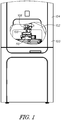
- Figure 1 shows one example of a testing instrument assembly 100.
- the testing instrument assembly 100 includes an instrument chamber 102 formed by an instrument housing 104.
- the instrument chamber 102 includes a testing instrument 106 provided therein.
- the testing instrument 106 includes a probe configured to extend through an environmental conditioning assembly 108, for instance through an enclosure housing 110, and accordingly engage and measure characteristics of a sample positioned within the housing 110.
- the environmental conditioning enclosure 108 is shown below the testing instrument 106.
- the environmental conditioning assembly 108 includes the enclosure housing 110 providing an environmental cavity therein.
- the environmental cavity provides a space for a stage as well as a sample positioned on the stage. That is to say, the sample is positioned within the environmental cavity and is accordingly surrounded by the walls of the enclosure housing 110.
- the enclosure housing 110 is clustered around the sample positioned within the enclosure housing 110 and accordingly a perimeter of the enclosure housing such (e.g., a cavity perimeter) is immediately adjacent to and surrounds the sample to minimize the volume of the environmental cavity relative to a volume of the instrument chamber 102.
- the environmental conditioning assembly 108 provides a conditioned localized environment for the sample therein.
- the instrument chamber 102 has a volume much larger than the volume of the environmental cavity within the enclosure housing 110. Accordingly, the environmental cavity of the enclosure housing 110 is quickly conditioned, including, but not limited to, heating, cooling or conditioning with one or more fluids (e.g., gases or liquids) and the like to provide a desired environment for a sample during testing (e.g., with the testing instrument 106).
- the environmental conditioning assembly 108 provides a localized environment isolated from the remainder of instrument chamber 102. Accordingly, heating, cooling, environmental conditioning and the like are localized to the sample and accordingly are not distributed throughout the instrument chamber 102.
- the sample within the enclosure 108 is isolated from an exterior environment including undesired conditions and fluctuations for instance changes in temperature, humidity, atmosphere composition or the like in the area surrounding the testing instrument assembly 100 (and within the instrument chamber 102). Testing of the sample is thereby readily conducted under one or more desired environmental conditions without interaction with the surrounding environment including the instrument chamber 102 or an environment surrounding the testing instrument assembly 100 (e.g., ambient atmosphere or the like).
- the environmental conditioning assembly 108 includes an enclosure housing 110.
- the enclosure housing 110 includes a bottom jacket 200 and a top jacket 202 coupled together to form the environmental cavity 206 therein.
- the enclosure housing 110 is coupled with a base plate 204.
- the base plate provides a support to the enclosure housing 110, for instance, by way of one or more posts (e.g., jacket supports that support the bottom jacket 200 and accordingly support the remainder of the enclosure housing 110).
- the housing 110 (e.g., the enclosure housing) includes a testing instrument access port 218 extending to the environmental cavity 206 and providing access to a sample within the cavity.
- the testing instrument access port 218 is sized and shaped to permit the passage of an instrument, such as a probe of the testing instrument 106 therethrough.
- the testing instrument access port 218 is dimensioned to facilitate free movement of a probe within the port (e.g., vertically along a Z axis and optionally along one or more of X or a Y lateral axes). Accordingly, the access port 218 provides a gap between an instrument extending through port and the inner perimeter of the port.
- the testing instrument access port 218 provides access to the sample, while the remainder of the housing 110 maintains the desired environment within the cavity 206.
- the environmental conditioning assembly 108 for instance through the testing instrument access port 218, provides ready access to a sample with the environmental cavity 206 for one or more testing instruments configured to conduct a variety of tests.
- the testing assembly 106 or another testing assembly used with the environmental conditioning assembly 108 is operable to conduct one or more of micro or nano indentation, compression testing, attractive force measurement testing, scratch testing, wear testing, material fracture testing, in-situ topography imaging, creep testing, dynamic mechanical testing and all within the controlled environment provided by the assembly 108.
- the housing 110 is configured to provide an isolated environment to a sample within the environmental cavity 206.
- heat transfer to and from the environmental cavity 206 is throttled through a combination of one or more of active heating or cooling, material selection of the housing 110 and insulation and minimizing access to the environmental cavity (e.g., through a limited number of orifices or ports).
- the housing 110 includes cooling inlets and outlets 208, 210 in one or both of the bottom and top jackets 200, 202.
- a cooling or heating fluid is provided through the inlets and outlets 208, 210 and corresponding passages extending through one or both of the bottom and top jackets 200, 202.
- the fluid conducted through the inlets and outlets 208, 210 is a cooling fluid configured to accordingly cool the bottom and top jacket 200, 202 for instance to room temperature while the sample within the environmental cavity 206 is heated for instance with one or both of a sample heater or a top heater as described herein.
- the inlets and outlets 208, 210 of the bottom and top jackets 200, 202 are used to conduct a heated fluid through passages in the jackets to maintain the jackets 200, 202 at a desired temperature (e.g., room temperature). Expansion and contraction of the housing 110 (and nearby components of the testing instrument 106) and thermal mechanical drift are accordingly minimized.
- thermal insulation materials such as a ceramic foam is included within the housing 110 to isolate the housing (constructed in one example with copper bottom and top jackets 200, 202) from heating or cooling of the sample within the environmental cavity 206.
- the environmental conditioning assembly 108 includes a plurality of interfaces configured to operate one or more of heaters or sensors positioned within or adjacent to the environmental cavity 206.
- the top jacket 202 includes a top heater interface 212 sized and shaped to provide electrical connection with the top heater associated with the top jacket 202.
- the top jacket 202 includes a sensor interface 214.
- the sensor interface 214 includes one or more thermocouple leads coupled to a thermocouple in the top heater coupled with the top jacket 202.
- the sensor interface 214 is coupled with another temperature sensor (or other type of sensor) provided within the environmental cavity 206.
- the bottom jacket 200 includes in one example a bottom heater interface 216 (and bottom sensor interface). As will be described herein the bottom heater interface 216 is coupled with a sample heater provided with a sample stage.
- the bottom jacket 200 includes another interface, in a similar manner to the top jacket 202, configured to provide a sensor interface to a temperature sensor or other sensor associated the environmental conditioning assembly 108.
- the environmental conditioning assembly 108 includes a baseplate 204.
- One example of the baseplate 204 is sized and shaped for coupling with a stage surface of an overall instrument, such as the testing instrument assembly 100.
- the baseplate 204 provides a solid kinematic base for the housing 110 and accordingly allows for accurate positioning of the environmental conditioning assembly 108 with regard to the testing instrument 106.
- a translational stage e.g., of the testing instrument assembly 100
- the enclosure 108 and the testing instrument access port 218 are movable to accurately align the testing instrument access port with a probe of the testing instrument 106.
- the solid base provided by the baseplate 204 minimizes lateral movement of the testing instrument access port 218 (e.g., shaking caused by translation of the enclosure 108) and ensures that an instrument delivered through the port does not undesirably engage the port perimeter.
- the baseplate 204 is coupled with a static stage of the testing instrument assembly 100 and the testing instrument 106 is otherwise movable relative to the testing instrument access port 218 to align a probe with the access port.
- FIG 3 shows a cross-sectional view of the housing 110 previously shown in Figure 2 .
- the housing 110 includes a sample stage 300 positioned within a portion of the bottom jacket 200.
- the sample stage 300 includes a stage surface 306 sized and shaped to receive a sample thereon.
- the sample stage 300 further includes a sample heater 304 localized to the sample stage 300 (for instance potted within the stage) and thereby able to readily heat a sample positioned on the sample stage 300.
- a bottom insulation ring 308 is in one example interposed between the sample stage 300 and the remainder of the bottom jacket 200 to accordingly throttle heat transfer from the sample stage 300 to the remainder of the bottom jacket 200. Accordingly the sample stage 300 in combination with the sample heater 304 provides localized heating to a sample positioned on the stage surface 306.
- a top heater 312 coupled with the top jacket 202 is provided in close positional relationship relative to the sample stage 300. That is to say, within the environmental cavity 206 the sample heater 304 and the top heater 312 are positioned in close proximity with a sample positioned on the sample stage surface 306. As will be described herein, in one example the sample stage 300 cooperates with the top heater 312 to provide clamping with surface to surface contact for a sample positioned therebetween. Accordingly, a sample positioned between the sample stage 300 and the top heater 312 receives conductive heating from both the top heater 312 and the sample heater 304 to provide consistent thorough heating throughout the sample and accordingly substantially minimize sample temperature gradients.
- the sample heater 304 and the top heater 312 are heated to different temperatures and thereby providing a desired heating gradient within the sample.
- the sample may be tested with either of these scenarios according to a consistent temperature or a desired temperature gradient provided by the sample heater 304 and the top heater 312 according to the desires of the testing technician.
- a top insulation ring 310 is in one example interposed between the top heater 312 and the remainder of the top jacket 202 to accordingly throttle heat transfer from the top heater 312 to the remainder of the top jacket 202.
- the bottom and top insulation rings 308, 310 cooperate to thermally isolate the sample stage 300, the top heater 312 and a sample on the sample stage from the remainder of the environmental conditioning assembly 108. Accordingly, the sample heater 304 provided with the sample stage and the top heater 312 provide localized heating (or cooling) to a sample positioned on the stage surface 306 while the remainder of the housing 110 is insulated from such heater (or cooling).
- the sample heater 304 (and the top heater 312) heat samples within the environmental cavity 206 over a range of temperatures.
- one or more of the sample heater 304 and the top heater 312 are configured to reach temperatures (and accordingly heat samples) of at least 1500 degrees Celsius.
- one or more of the sample heater 304 and the top heater 312 are configured to reach temperatures of 500, 750, 1000, 1200 degrees Celsius or the like.
- the environmental conditioning assembly 108 through one or more mechanisms constrains heating (and cooling as well) to the enclosure cavity 206 through insulation within the cavity 206 (such as foam ceramic insulation found in the bottom and top insulation rings 308, 310), active cooling (or heating) of the housing 110 through the cooling or heating inlets and outlets 208, 210 and passages within the housing. Accordingly, even at the high temperatures generated with the heaters 304, 312 heating is localized to the sample, and heat transfer is substantially throttled to the remainder of the housing 110 as well as the environment exterior to the housing 110.
- a jacket seal 314 is provided around the environmental cavity 206.
- the jacket seal 314 is in one example provided by a deflectable material, such as silicone rubber or another material configured to withstand extremely high temperatures generated within the environmental cavity while at the same time maintaining the seal between the top and bottom jackets 202, 200.
- the jacket seal 314 includes, but is not limited to, silicone, fluorocarbon elastomers, PTFE, flexible metal (e.g., a bellows type seal or the like.
- the jacket seal 314 encircles at least a portion of the environmental cavity 206 and accordingly seals the environmental cavity (excepting the testing instrument access port 218 and the optional environmental conditioning inlets and outlets described herein).
- the enclosure housing is optionally formed as a two part assembly including the bottom and top jackets 200, 202.
- one or more guideposts 320 extending from one or the other of the top or bottom jackets 202, 200 are sized and shaped for reception within corresponding passages 321 provided within the bottom jacket 200.
- the passages 321 include linear bearings. The linear bearings provide a snug movable engagement with the guideposts 320 and thereby constrain movement of the top jacket 202 as the top jacket is coupled with the bottom jacket 200.
- the guidepost 320 are slidably received within the linear bearings of the passages 321 and accordingly guide the top jacket 202 downwardly as the top jacket is lowered into engagement with the jacket seal 314 to close the environmental cavity 206.
- the gradual lowering of the top jacket 202 e.g., with the guideposts 320 and the passages 321) constrains lateral movement of the top jacket 202 and accordingly facilitates downward movement along a Z axis.
- the top heater 312 moves downward toward the sample stage 300 and a sample positioned on the stage surface 306 the top heater 312 is able to engage with the sample provided on the sample stage 300 in surface to surface contact without relative lateral movement between the sample and the top heater 312.
- the sample is accordingly retained between the sample stage 300 and the top heater 312 through vertical clamping with substantially no appreciable lateral movement between either of the samples stage 300 or the top heater 312 relative to a sample clamped therebetween.
- the environmental conditioning assembly 108 provides an expansion and contraction linkage configured to maintain a sample at a desired elevation, for instance, while the sample is heated or cooled at a steady state temperature.
- a desired elevation for instance, while the sample is heated or cooled at a steady state temperature.
- steady state temperatures e.g. 1500 degrees Celsius
- minor fluctuations with regard to voltage applied to the sample heater 304 and the top heater 312 result in corresponding fluctuations of heating of the sample and the sample stage 300.
- the corresponding fluctuations in temperature provide dynamic elevation changes through expansion, contraction, thermomechanical drift and the like to the components of the environmental conditioning assembly 108. Accordingly, measurement errors caused by these fluctuations may be introduced to testing procedures conducted with the testing instrument 106 shown in Figure 1 .
- the expansion and contraction linkage minimizes these elevation changes caused by fluctuation from the steady state temperature.
- the expansion and contraction linkage includes a plurality of components shown in Figure 3 and further described herein.
- the linkage includes an interface member 316 provided between an interface for one or more jacket supports 318 as well as one or more stage supports provided between the sample stage 300 and the interface member 316.
- the jacket supports 318, the interface member 316, as well as the stage supports cooperate during heating or cooling of a sample positioned on the sample stage 300 to correspondingly minimize elevational changes caused by fluctuations from a steady state temperature.
- the environmental condition enclosure 108 facilitates the localized conditioning of an environment around a sample, for instance, a sample positioned on the sample stage 300.
- the environmental cavity 206 provides a compact localized environment allowing for one or more of heating or cooling of a sample positioned on the sample stage 300, as well as the introduction of one or more conditioning fluids through one or more ports provided within the housing 110.
- an environmental conditioning inlet 322 is provided in one or more of the bottom and top jackets 200, 202.
- the environmental conditioning inlet 322 shown in Figure 3 extends to and is communication with the environmental cavity 206 and is accordingly able to deliver one or more gases, fluids or the like (inert, reactive, heated, cooled or the like) to the environmental cavity 206.
- gases, fluids or the like inert, reactive, heated, cooled or the like
- the introduction of these fluids conditions the environment within the environmental cavity 206 according to the desired testing parameters.
- the top jacket 202 as shown in Figure 3 includes an environmental conditioning outlet 324.
- the environmental conditioning outlet 324 provides a return outlet for fluids delivered into the environmental cavity 206, for instance by way of the environmental conditioning inlet 322 previously described.
- a gas delivery channel 326 is provided along the top jacket 202 to provide inert gas delivery to the testing instrument access port 218.
- the inert gas delivery conditions the environment local to the testing instrument access port 218 as well as an instrument probe extending therethrough.
- the gas delivery channel 326 is used in at least one example to condition fluids exiting the environmental cavity 206 to substantially prevent undesirable cooling or heating of a probe shaft or a transducer coupled with the probe shaft otherwise caused by heating or cooling within the environmental cavity 206.
- the environmental conditioning inlet 322 is configured to provide a flow of an inert gas into the environmental cavity 206 including, but not limited to, argon, nitrogen or some combination of gases such as argon and hydrogen.
- the inert gas is provided to the environmental cavity 206 and accordingly the sample disposed therein to provide a non-oxidizing environment for the sample.
- high temperatures e.g., 1500 degrees Celsius. In an otherwise ambient atmosphere high temperatures may oxidize the sample and accordingly undesirably change its mechanical properties prior to testing with the testing instrument 106 shown in Figure 1 .
- the environmental conditioning inlet 322 provides one means for introducing inert gases and other environmental control fluids into the environmental cavity 206.
- the environmental conditioning inlet 322 provides an inert gas as described above.
- the inert gas 322 provides one or more of a heating or cooling fluid to the environmental cavity 206 that correspondingly heats or cools the environment provided within the environmental cavity 206 while at the same time also heating or cooling the sample positioned on the sample stage 300.
- the environmental conditioning outlet 324 provided optionally in the top jacket 202 is used in one example to remove fluid from the environmental cavity 206.
- the environmental conditioning outlet 324 and the environmental conditioning inlet 322 cooperate to provide a flow of fluids into the environmental cavity 206 throughout a testing procedure for a sample positioned on the sample stage 300.
- the environmental conditioning inlet 322 is used to provide other conditioning fluids to the environmental cavity 206.
- the fluid provided to the environmental cavity 206 in one example is a humidified stream of gas provided from a chamber of humidified gas in communication with the environmental conditioning inlet 322.
- the gas delivery channel 326 is configured to provide a flow of gas to the testing instrument access port and accordingly interrupts a flow of fluid from the environmental cavity 206 otherwise extending through the testing instrument access port 218 possibly rising along a probe shaft toward a transducer of the testing instrument 106 shown in Figure 1 .
- the gas delivery channel 326 in one example provides a stream of cooled gas (such as an inert cooled gas) to the testing instrument access port 218 to substantially interrupt and prevent the upward flow of heated gases along a probe shaft. By interrupting the flow of heated gases along the probe shaft corresponding heating of sensitive instrumentation and transducers within the testing instrument 106 is substantially avoided.
- the environmental conditioning assembly 108 provides a large temperature drop between the sample stage 300 and the top heater 312 to the bottom and top jackets 200, 202.
- the temperature drop at the interface of the environmental cavity 206 to the housing 110 minimizes thermal expansion (or contraction with cooling) of the heating stage during the heating operation. Further, a steep temperature drop through the housing 110 also reduces the overall heated volume of the enclosure 108 and correspondingly the power needed for heating. Further still, by minimizing the heating (or cooling) of the enclosure 110 thermomechanical drift of the enclosure 108 is also minimized.
- a steep temperature drop is realized by providing a large thermal resistance through the enclosure 108 using one or more of the bottom and top insulating rings 308, 310 or the heating or cooling inlets and outlets 208, 210 shown in Figure 2 .
- the sample stage 300 is seen from below thereby exposing the sample heater 304 as well as a plurality of pin recesses 402 arranged around the sample stage 300.
- the sample heater 304 includes a heating element extending between two or more heating element leads 406.
- the sample heater 304 (the heating element) is a wire coil configured for potting within the sample stage 300.
- the sample heater 304 accordingly provides heating to the sample stage 300 in a distributed fashion across the stage surface 306 to accordingly heat a sample positioned thereon.
- a stage thermocouple 410 is also provided with the sample stage 300.
- Thermocouple leads 408 extend from the thermocouple 410 for coupling with an interface extending from the bottom jacket 200 shown in Figure 2 .
- the heating element leads 406 are coupled with a bottom heater interface 216 as shown in Figure 2 .
- the pin recesses 402 constrain heat transfer by limiting the interface between the sample stage 300 and the underlying stage supports.
- the pin recesses 402 each have a tapered shape that provides two point contact (as opposed to surface to surface contact) between the sample stage and a stage support.
- the sample stage 300 includes a plurality of pin recesses 402.
- the tapered configuration of each of the pin recesses 402 is sized and shaped to receive a corresponding stage support therein.
- the tapered pin recesses 402 provide for at least two point engagement with each of the respective stage supports and accordingly provide stable support to the sample stage 300 at each of at least three locations along the stage.
- three pin recesses 402 are provided on the sample stage 300 to provide three point support for the sample stage 300 and accordingly a stable kinematic surface for the positioning and testing of samples on the stage surface 306.
- the sample stage 300 has dual thicknesses.
- a first thickness 412 is measured between the stage surface 306 and an opposed stage surface 400 and a second thickness 414 is measured between the stage surface 306 and a recess trough 404 of the pin recess 402.
- the second smaller thickness 414 of the sample stage 300 is used in one example to minimize the effect of thermomechanical drift and expansion or contraction of the sample stage 300 on testing of a sample coupled with the sample stage 300.
- the second thickness cooperates with operation of the expansion and contraction linkage described herein.
- the second thickness 414 corresponding to the distance between the recess trough 404 and the stage surface 306 substantially minimizes the expansion and contraction of the sample stage 300 during heating.
- any expansion or contraction of the sample stage 300 as it applies to elevation changes of the sample is limited to the second thickness 414 (and not the overall larger first thickness 412).
- the remainder of the sample stage for instance, that portion of the stage 300 below the second thickness (e.g., the remainder of the first thickness) is substantially ignored during expansion or contraction as it extends remotely relative to the stage supports and otherwise provides no additive or subtractive elevation to the sample positioned on the stage surface 306.
- the second thickness 414 is about zero (0) millimeters as the recess trough 404 is positioned immediately adjacent to or coincident with the stage surface 306.
- the recess trough 404 opens onto the stage surface 306 thereby accordingly positioning an appropriately sized stage support positioned within the pin recess 402 immediately adjacent to the stage surface 306.
- the sample heater 304 is installed with the sample stage 300 by potting a heater wire into grooves on the back side of the sample stage 300.
- the grooves are optionally formed between the housings for each of the pin recesses 402.
- the sample stage 300 is constructed with, but not limited to, aluminum nitride.
- Figure 4 shows the coiled heater wire of the sample heater 304 along the sample stage 300.
- the thermocouple 410 (such as a .005" wire diameter Type K; Part number CHAL-005 from Omega) is also potted within the groove.
- the heater wire is made from a material such as Nichrome or Kanthal configured to withstand high temperatures (e.g., temperatures of at least 1500 degrees Celsius) with minimal oxidation.
- a refractory coating is optionally used to coat the heating element wires.
- the heater wire diameter of the sample heater 304 is between about 0.003 to 0.0035 inches, and the heater wire length is selected to provide a resistance of about 25 Ohms.
- the sample heater 304 (coiled heater wire) is attached to the larger heating element leads 406 with a crimping bead.
- the heating element leads 406 are also constructed with Nichrome or Kanthal are several times larger than the heater wire used in the sample heater 304 to minimize the resistive heating in the lead wires.
- FIG 5 shows one example of a top heater 312 (previously shown in Figure 3 ).
- the top heater 312 includes a plurality of features similar in at least some regards to the sample stage 300 previously shown in Figure 4 .
- the top heater 312 includes a potted heating element 502.
- the heating element 502 in one example includes a wire coil coupled with heating element leads 504 extending away from the top heater 312 as shown in Figure 5 .
- a temperature sensor such as a top heater thermocouple 506 is also positioned within the top heater 312.
- Thermocouple leads 508 extend away from the top heater thermocouple and are configured for coupling with the corresponding sensor interface 214 shown in Figure 2 .
- the heating element leads 504 coupled with the top heater 312 are correspondingly configured for coupling with the top heater interface 212 also shown in Figure 2 .
- the top heater 312 cooperates with the sample stage 300 to clamp a sample positioned therebetween in surface to surface contact.
- a clamping surface 500 is provided on the top heater 312.
- the clamping surface 500 is sized and shaped to correspondingly engage with the sample position on the sample stage 300.
- the top jacket 202 descends relative to the bottom jacket 200 until the clamping surface 500 engages with the sample and accordingly clamps the sample between the clamping surface 500 and the sample stage 300.
- the descending top jacket 202 in one example engages with the jacket seal 314 extending between the top and bottom jackets 202, 200 to close the environmental cavity 206 and thereby provide the isolated environment for the sample within the environmental cavity 206.
- the top heater 312 includes one or more fluid channels 510 extending across a portion of the top heater 312, for instance through the clamping surface 500. As shown in Figure 5 , the fluid channels 510 extend through the top heater 512 after extending laterally across the top heater toward the clamping surface 500. That is to say, the fluid channels 510 extend upwardly through the top heater 312 and are accordingly in communication with the testing instrument access port 218.
- the environmental conditioning inlet 322 including one or more of heated or cooled fluids, environmental conditioning fluids, and the like
- these fluids are delivered through the fluid channels 510 to accordingly condition substantially the entire environment of the environmental cavity 206 including that portion of the environmental cavity immediately above the sample on the sample stage 300.
- the conditioning fluids are thereafter delivered upwardly in one example through the testing instrument access port 218 and are removed with the environmental conditioning outlet 324.
- the top heater 312 is constructed with, but not limited to, aluminum nitride. As shown in Figure 3 , the top heater 312 is optionally surrounded by the insulation ring 310, for instance a ceramic foam material, such as Cotronics Rescor 310. The top heater 312 is retained within the top jacket 202 by fasteners, such as screws, pins, rivets or the like. Optionally, the fasteners are made of Zirconia having a low thermal conductivity to minimize heat transfer to the jacket 202.
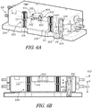
- FIG 6A is a cross-sectional view of the environmental conditioning assembly 108 previously described herein.
- the top jacket 202 is removed to expose the bottom jacket 200 coupled with the base plate 204.
- the bottom jacket 200 is suspended above the base plate 204 with a plurality of jacket supports 318 (e.g., interface supports).
- the jacket supports 318 have a length greater than the distance between the support interface 612 and the bottom of the bottom jacket 200. Accordingly, the jacket supports 318 suspend the bottom jacket 200 as well as the remainder of the enclosure housing 110 above the base plate 204.
- the housing 110 is substantially isolated from the remainder of the environmental conditioning assembly 108 by way of the jacket supports 318.
- the jacket support 318 accordingly throttle heat transfer from the housing 110 to the remainder of the environmental conditioning assembly 108, such as the base plate 204 as well as any features coupled with the base plate (for instance, one or more components of the testing instrument assembly 100).
- the expansion and contraction linkage 600 includes the jacket supports 318, an interface member 316, and the plurality of stage supports 602 extending between the interface member 316 and the sample stage 300.
- the jacket supports 318 extend from the base plate 204 to a support interface 612 of the interface member 316.
- the interface member 316 extends from the support interface 612 to a stage interface 614 coupled with the stage support 602.
- the stage supports 602, for instance support pins for the stage 300 extend upwardly from the stage interface 614 to support the stage 300.
- the stage supports 602 are received within the pin recesses 402 including recess troughs 404.
- the expansion and contraction linkage 600 accordingly provides a linkage extending from the sample stage 300 to the base plate 204.
- the expansion and contraction linkage 600 maintains the elevation of the sample stage 300 and a sample thereon substantially static while the sample stage and the sample experience fluctuations in temperature that would otherwise cause elevational changes (and corresponding measurement error with an instrument engaged with the sample).
- the interface member 316 is incorporated into and is part of the bottom jacket 200.
- the interface member 316 is a portion of the bottom jacket 200 between the support interface 612 and the stage interface 614.
- the stage interface 614 is recessed relative to the support interface 612.
- the interface member 316 is separate from the bottom jacket 200.
- the interface member 316 is a separate component extending between the support interface 612 and the stage interface 614. Accordingly, in such an example the interface member 316 is a separate component from the bottom jacket 200 and is dedicated to the expansion and contraction of the linkage 600.
- the jacket supports 318 include a column body 606 extending between the base plate 204 and the support interface 612.
- the column body 606 outer diameter is smaller than a support cavity 608 inner diameter sized and shaped to receive the jacket supports 318 therein.
- the column body 606 when positioned within the support cavities 208 (and centered, for instance by one or more support posts 604, such as screws, pins or the like coupled with the jacket 200 and the base plate 204) provides a gap between the jacket support 318 and the bottom jacket 200.
- the gap between the jacket support 318 and the remainder of the bottom jacket 200 allows for independent movement of each of the jacket supports 318 as well as the interface member 316 during operation of the expansion and contraction linkage 600. Stated another way, the jacket 200 is isolated from at least the jacket supports 318 and accordingly does not interfere with expansion or contraction of the supports.
- the bottom jacket 200 includes linear bearings sized and shaped to receive the guidepost 320 therein.
- the cooperation of the guidepost 320 and the linear bearings 616 e.g., within the passages 321) allows the top jacket 202 to easily descend toward the bottom jacket 200 due to gravity and accordingly close the environmental cavity 206.
- the guideposts 320 cooperate with the bottom jacket 200 to suspend the top jacket 202 upon the bottom jacket and accordingly ensure that the top jacket 202 does not interfere with operation of the expansion and contraction linkage 600.
- the expansion and contraction linkage 600 is shown in a cross-sectional view.
- the expansion and contraction of the linkage 600 includes one or more stage supports 602, the interface member 316 coupled with the stage supports 602, and the jacket supports 318 also coupled with the interface member 316.
- the interface member 316 includes two components, for instance the support interface 612 sized and shaped to engage with the jacket supports 318 and the stage interface 614 sized and shaped to engage with the stage support 602.
- the stage interface 614 as shown is recessed a length 601 (e.g., about 1 mm) relative to the support interface 612.
- the jacket supports 318 and the stage supports 602 have corresponding lengths that cooperate with the recessed stage interface 614 to ensure a net elevation change of about 0 mm with expansion and contraction of the linkage 600 through heating or cooling within the housing 110 (of the housing itself), as described herein.
- the jacket supports 318 have lengths 603 of about 25 mm
- the stage supports 602 have lengths 605 of around 9.5 mm. The lengths in combination with the materials chosen for the components of the linkage minimize any elevation change.
- the recessing of the stage interface 614 relative to the support interface 612 provides a cooperative counter movement to corresponding expansion and contraction of each of the stage supports 602 and the jacket supports 318.
- the stage supports 602 and the jacket supports 318 receive at least some measure of heat transfer from the sample stage 300 and accordingly expand upwardly relative to the stage interface 614 and the base plate 204, respectively.
- the expansion of the jacket supports 318 biases the support interface 612 upwardly.
- the interface member 316 expands in an opposite direction relative to the expansion of each of the stage supports 602 and the jacket supports 318 because stage interface 614 is relative to the support interface 612.
- the interface member 316 expands downwardly relative to the upward expansion of the stage supports 602 and the jacket supports 318.
- the converse occurs with cooling in the environmental cavity. That is to say, the stage supports 602 and the jacket supports 318 contract in a first direction, while the interface member 316 contract in an offsetting second direction. Accordingly, the net translation of the expansion and contraction linkage 600 whether during heating or cooling at a steady state temperature is a net elevation change of 0 with fluctuations from the steady state temperature.
- the expansion and contraction linkage 600 operates to offset expansion or contraction otherwise generated by these temperature fluctuations at the stage surface 306. Accordingly, the sample elevation on the sample stage 300 as shown in Figure 6A remains substantially static even with fluctuations in temperature relative to a steady state temperature (whether heated or cooled). Measurements, for instance measurements conducted with the testing instrument 106 of the testing instrument assembly 100, are thereby conducted with a substantially static sample (when heated or cool) as opposed to a sample that moves based on temperature fluctuations from a desired steady state temperature.
- Figure 7 shows a schematic view of the expansion and contraction linkage 600 previously described and shown in Figures 6A and 6B .
- the left most arrows of each pair of arrows associated with the stage supports 602, interface member 316, and the jacket supports 318 corresponds to of at least the sample stage 300 along with incidental heat transfer to the remainder of the housing 110.
- the right most arrows of the paired arrows for each of the stage supports 602, the interface member 316 and the jacket supports 318 corresponds to cooling of the stage 300 and optionally the environmental cavity 206 for instance through the provision of a chilled or cooled fluid provided by the environmental conditioning inlet 322 (as shown in Figure 3 ).
- the downward movement of the interface member 316 in the heated condition offsets the corresponding upward movement provided by the stage supports 602 and the jacket supports 318 caused by expansion of each of these components.
- the upward relative movement of the interface member 316 offsets the corresponding downward movement of the stage support 602 and the jacket supports 318 during cooling within the environmental cavity 206 caused by contraction of each of these components of the linkage 600.
- each of the stage supports 602, jacket supports 318, as well as the interface member 316 are chosen according to their thermal mechanical properties including their coefficients of thermal expansion, thermal conductivities, and the like.
- the interface member 316 is able to offset expansion and contraction of both of the stage supports 602 and the jacket supports 318 during either of heating or cooling.
- the interface member 316 moves in an opposite direction relative to the stage supports 602 and the jacket supports 318 and is able to offset expansion or contraction of these features and accordingly maintain the stage surface 306 with the sample thereon at a desired elevation (for instance as the state 300 is subjected to temperature variations from a steady state temperature).
- the sample stage 300 includes the recess troughs 404 positioned immediately adjacent to the stage surface 306 (also shown in Figure 4 ). Placing the recess troughs 404 in close proximity to the stage surface 306 ensures expansion or contraction of the sample stage 300 and a corresponding elevation change of the surface 306 is substantially mitigated or minimized by the close and intimate engagement of the stage supports 602 at the stage surface 306. That is to say, the second thickness 414 (also shown in Figure 4 ) is substantially minimized by providing the recess troughs 404 immediately adjacent to the stage surface 306 or coincident with the stage surface 306.
- expansion or contraction of the sample stage 300 during heating or cooling is correspondingly minimized with regard to its effect on the sample elevation (e.g., has a minimal effect on operation of the expansion and contraction linkage 600).
- the expansion and contraction linkage 600 as described herein is thereby able to maintain the stage surface 306 and a sample positioned thereon at a substantially static elevation even with temperature fluctuations from a steady state temperature.
- the expansion and contraction linkage 600 shown in Figures 6A , B is a demonstrative example having the characteristics provided in the expansion and contraction equations provided below.
- the interface member 316 minimizes the Z-Displacement of the stage supports 602 and the jacket supports 318 caused by heating or cooling relative to a steady state temperature.
- the interface member 316 changes temperature ( ⁇ T)
- the average temperature change of the stage supports 602 is about half of the temperature change of the interface member 316 because the temperature at the top end of the stage supports is controlled by the sample stage 300 temperature.
- the average temperature change of the jacket supports 318 is also about half of the temperature change of the interface member 316 (e.g., optionally the bottom jacket 200) because the temperature of the bottom ends of the jacket supports 318 is determined by the temperature of the underlying base plate 204.
- the Z-displacement caused by a temperature change in the environmental conditioning assembly 108 (and attenuated by the expansion and contraction linkage 600) is the sum of the Z-displacements of the stage supports 602, the interface member 316 and the jacket supports 318. The dimensions and materials for each these components are selected so that the Z-displacements sum to approximately zero.
- the jacket supports 318 are made of a low coefficient of thermal expansion material including, but not limited to, Invar.
- the interface member 316 (e.g., the bottom jacket 200) is made of copper and has a moderate coefficient of thermal expansion relative to the other components.
- the stage supports 602 are constructed with, but not limited to, Quartz having a low coefficient of thermal expansion relative to at least interface member 316.
- FIG 8 shows a schematic view of a portion of the environmental conditioning assembly 108.
- the top jacket 202 is coupled along a portion of a sample 806 provided on the sample stage 300.
- the sample 806 is clamped between the top jacket 202, for instance the top heater 312, and the sample stage 300 including the sample heater 304 therein.
- the clamping engagement of the sample 806 provides surface to surface contact with the sample 806 and accordingly facilitates conductive heat transfer at both opposed surfaces of the sample 806 corresponding to the interfaces with the top heater 312 and the stage surface 306 (the sample heater 304 is optionally within the sample stage 300).
- the top jacket 202 includes one or more guideposts 320 sized and shaped for reception within passages 321 of the bottom jacket 200.
- linear guide bearings 616 are provided in the passages 321 and are configured to snuggly receive the guideposts 320 therein and guide the top jacket 202 along a substantially vertical axis into engagement with the sample 806 as shown in Figure 8 . Accordingly, as the top heater 312 engages with the sample 806 (e.g., at the clamping surface 500 previously shown in Figure 5 ) the top heater 312 provides substantially no lateral movement to the sample 806.
- the sample 806 is stably engaged by the top heater and clamped between the sample stage 300 and the clamping surface 500 with substantially no lateral movement imparted to the sample 806.
- a fixation feature such as a spring clamp or the like is applied to the top and bottom jackets 202, 200 to further immobilize the clamping engagement between the top heater 312 and the sample stage 300.
- the construction of the bottom and top jackets 200, 202 for instance with copper plates affirmatively clamps the sample 806 between the top heater 312 (e.g., included in the top jacket 202 and the sample stage 300 provided in the bottom jacket 200) due to gravity.
- the top heater 312 in at least one example includes a plurality of fluid channels 510.
- the fluid channels 510 allow for communication between the testing instrument access port 218 and the remainder of the environmental cavity 206.
- an environmental conditioning fluid is supplied to the environmental cavity 206, for instance by the environmental conditioning inlet 322 shown in Figure 3
- the environment provided in the environmental cavity 206 extends into the testing instrument access port 218 (e.g., the portion of the environmental cavity 206) immediately above the sample 806. Accordingly, the entirety of the sample 806 is maintained within the environment of the environmental cavity 206.
- a probe 800 for instance of the testing instrument 106 shown in Figure 1 , extends through the testing instrument access port 218 to engage with the sample 806.
- the probe 800 engages the sample 806 within that provided environment (e.g., heated, cooled, conditioned with one or more fluids or the like). Stated another way, the testing instrument access port 218 in in communication with and is part of the environmental cavity 206.
- the clamping engagement between the top heater 312 and the stage 300 is configured to provide consistent reliable heating throughout the sample 806.
- the surface to surface contact provided by the clamping engagement readily conducts heat into the sample 806.
- the top heater 312 and the sample heater 304 are heated to the same temperature the sample 806 has a substantially minimized temperature gradient between the opposed surfaces engaged with the top heater 312 and the sample stage 300.
- the top heater 312 and the sample heater 304 are heated to varying degrees. For instance, the top heater 312 is heated to a first temperature while the sample heater 304 is heated to a second temperature different from the first temperature of the top heater 312.
- the clamped sample 806 is provided with a gradient of temperatures from its top most surface adjacent to the clamping surface 500 to its bottom most surface adjacent to the stage surface 306. Accordingly where it is desirable to measure properties of the sample according to temperature gradients therein such a temperature gradient is provided by the clamping engagement achieved with engagement of the top heater 312 and the sample stage 300 with the sample 806.
- the probe 800 includes one or more electrical contacts 808 at the probe tip 804.
- the sample stage 300 includes one or more corresponding electrical contacts 810.
- the electrical contacts 808, 810 are configured to engage the sample 806 held in clamping engagement between the top heater 312 and the sample stage 300.
- the testing instrument 106 previously shown in Figure 1 is used in cooperation with the sample stage 300 to perform one or more electrical characteristic tests of the sample 806. For instance, a potential is applied across the contact 808 of the probe 800 and the contact 810 of the sample stage 300 to accordingly measure one or more electrical characteristics of the sample 806 including but not limited to resistivity, conductivity, and the like.
- FIG 9 shows a schematic example of the environmental conditioning assembly 108.
- the environmental conditioning assembly 108 provides a housing 110 having an environmental cavity 206.
- the housing 110 includes bottom and top jackets 200, 202 coupled along a jacket seal 314.
- the environmental cavity 206 substantially isolates a sample within the environmental cavity while still providing access through a testing instrument access port 218. Additionally, the environmental cavity localizes a small environment to the area immediately adjacent to the sample, for instance by clustering the cavity perimeter of the enclosure housing 110 closely around the sample.
- the instrument chamber volume 102 is significantly larger than the corresponding volume of the environmental cavity 206.
- conditioning of the environment within the environmental cavity 206 is readily accomplished through one or more inlets or outlets providing environmental conditioning fluid as well as localized heating or cooling of the sample positioned on the sample stage 300 without corresponding heating and temperature fluctuations caused in larger environments (e.g., volumes larger than the cavity 206).
- an environmental conditioning system is provided.
- the environmental conditioning system extends through the environmental cavity 206, for instance by way of the environmental conditioning inlet 322 and one or more environmental conditioning outlets 324, 900.
- an environmental conditioning outlet 324 is provided within the top jacket 202, for instance adjacent to the testing instrument access port 218.
- the environmental conditioning outlet 324 optionally applies a negative pressure (e.g., a vacuum) within the testing instrument access port 218 and accordingly prevents the egress of fluids from within the environmental cavity 206.
- an environmental conditioning outlet 900 is provided on the opposed side of the environmental cavity 206 relative to the environmental conditioning inlet 322.
- the environmental conditioning outlet 900 facilitates the delivery of environmental conditioning fluids within the environmental cavity 206 and across a sample on the sample stage 300 to further ensure the environmental cavity 206 and the sample are exposed to heating or cooling fluids and any other environmental conditioning fluids delivered between the inlet 322 and the outlet 900.
- a coolant or heating fluid source 904 is provided in communication with the environmental conditioning inlet 322.
- the coolant or heating fluid source 904 includes a cooled or heated source of gas, liquid or the like provided at a desired temperature.
- the fluid is delivered by way of a conditioning pump 908 in communication with the environmental conditioning inlet 322.
- the conditioning pump 908 includes, but is not limited to, a pump, blower, fan, dripping mechanism, or the like.
- the environmental conditioning loop includes a conditioning fluid source 906 (e.g., in communication with the conditioning pump 908).
- the conditioning fluid source 906 includes, but is not limited to, one or more reservoirs of inert gas, air, reactive fluids, liquids, humidified gases and the like.
- the conditioning fluid source 906 includes a source of inert gas, such as a mixture of argon and hydrogen. As the inert gas is pumped (with the conditioning pump 908) into the environmental cavity 206 the surrounding environment of a sample therein is accordingly filled with the inert gas.
- the environment within the environmental cavity 206 correspondingly elevates in temperature for instance to a temperature of 1500 degrees Celsius.
- the inert gas present in the environmental cavity 206 oxidation of a sample on the sample stage 300 is substantially minimized. Accordingly, the testing of the sample (e.g., with the probe 800) is carried out in this elevated temperature without risk of oxidation of the sample therein.
- the conditioning fluid source 906 provides a source of humidified gas for instance a bubbled inert gas delivered through a bath of chilled water.
- the conditioning fluid source 906 provides a source of a reactive fluid configured to initiate a chemical reaction with the sample in the environmental cavity 206. Accordingly by delivering the reactive fluid into the environmental cavity 206 the reaction with the sample is localized and accordingly the probe 800 is able to examine the reacting sample within a small localized environment substantially isolated from environmental factors exterior to the environmental conditioning assembly 108.
- one or both of the environmental conditioning outlets 324, 900 are in communication with an extraction pump 912 and an extraction reservoir 910.
- the extraction pump 912 provides a negative pressure at one or more of the environmental conditioning outlets 324, 900.
- the environmental conditioning fluid provided by way of the environmental conditioning inlet 322 is drawn through the environmental cavity 206.
- a flow of environmental conditioning fluid is delivered at a constant flow rate through the environmental cavity 206 to substantially maintain the environment around the sample positioned on the sample stage 300.
- one or more of heating or cooling of the sample is provided and continuously maintained throughout a testing procedure according to the needs of the procedure (e.g., cooling to subfreezing temperatures or heating to temperatures approaching 1500 degrees Celsius).
- the environmental conditioning outlet 324 is positioned within the testing instrument access port 218 the outlet 324 is configured to withdraw any fluids provided by way of the environmental conditioning inlet 322 prior to egress of the fluid through the access port 218.
- a sample within the environmental conditioning assembly 108 must be maintained at the desired temperature during testing, for instance while engaged by the probe 800.
- a desired temperature e.g. 1500 degrees Celsius
- the temperature distribution from the sample to the probe 800 depends on the relative heat resistance through these components.
- the narrow heat flux through the very small contact area e.g., where the probe tip 804 engages the ample
- provides a large thermal resistance thermal resistance is inversely proportional to the area perpendicular to the heat flux).
- the large heat resistance near the contact area causes a large temperature drop at the contact area of the sample and in the nearby vicinity.
- the temperature of the contact zone upon engagement with the probe tip 804 is not the same as the overall sample temperature.
- the probe 800 (e.g., of the testing instrument 106 shown in Figure 1 ) extends into the environmental cavity 206 by way of the testing instrument access port 218.
- the probe tip 804 is correspondingly heated to an identical temperature.
- the probe tip 804 is readily heated to an identical temperature to the sample positioned on the sample stage 300.
- the bottom heater 304 and the sample positioned therebetween an environment is created locally around the probe tip 804 that correspondingly heats the probe tip 804, by radiation, to a temperature substantially identical to that of the sample on the sample stage 300.
- an environmental conditioning fluid such as heating or cooling fluids are provided through the environmental conditioning inlet 322 (or a fluid is heated by one of the heaters 304, 312) the environment within the environmental cavity 206 is correspondingly heated or cooled to a desired temperature.
- the probe tip 804 positioned within the environment of the environmental cavity 206 the probe tip is correspondingly convectively heated or cooled to the same desired temperature.
- the probe tip 804 upon engagement between the probe tip and the sample positioned on the sample stage 300 the probe tip 804 (when previously positioned within the environmental cavity 206) is at a substantially identical temperature. Accordingly heat transfer between the probe tip 804 and the sample on the sample stage 300 is substantially minimized. Instead, each of the probe tip 804 and the sample are at substantially the same temperature and accordingly the sample is tested at that elevated temperature without corresponding heat transfer from or to the probe tip 804. The sample thereby remains at the desired temperature throughout the testing procedure.
- the environmental conditioning assembly 108 includes a gas delivery channel 326 configured to provide a flow of gas to the probe 800.
- the probe 800 is coupled with sensitive electronics and measurement equipment in the testing instrument 106 (e.g., capacitive transducers, sensors and the like) that are sensitive to changes in temperature for instance provided by heating of the sample on the sample stage 300.
- the gas delivery channel 326 in one example interrupts the flow of heated fluid upwardly from the environmental cavity 206 (e.g., along the probe shaft of the probe 800) and toward the transducers of the testing instrument 106.
- the gas delivery channel 326 is coupled with an isolation fluid pump 912 and an isolation fluid source 914.
- the isolation fluid source 914 provides a heated or cooled flow of fluid (or optionally a room temperature flow of gas) that is pumped by way of the isolation fluid pump 912 to the transversely mounted gas delivery channel 326.
- the flow of gas from the gas delivery channel 326 crosses the probe shaft 802 of the probe 800 and accordingly interrupts the upward flow of any heated fluids from the testing instrument access port 218. That is to say, incidental flow of environmental conditioning fluids (such as gases, heated or cooled fluids, and the like) rising from the testing instrument access port 218 is interrupted by the flow of fluid from the gas delivery channel 326. Accordingly sensitive electronics, transducers and the like associated with the testing instrument 106 are preserved from the heated or cooled environment of the environmental cavity 206.
- Figure 10 shows one example of a method 1000 for using an environmental conditioning assembly, such as the environmental conditioning assembly 108 shown in Figures 1 and 2 .
- an environmental conditioning assembly such as the environmental conditioning assembly 108 shown in Figures 1 and 2 .
- reference numerals The reference numerals provided are exemplary and are not exclusive.
- the features components, functions, steps and the like described in the method 1000 include but are not limited to the corresponding numbered elements, other corresponding features described herein (both numbered and unnumbered) as well as their equivalents.
- the method 1000 includes positioning a sample such as the sample 806 on a sample surface (e.g., a stage surface 306) of a sample stage 300 within an environmental cavity 206 of a housing 110 (e.g., an enclosure housing 110).
- the cavity perimeter of the housing 110 is clustered around the sample stage 300 and the sample.
- the cavity perimeter corresponds to the inner perimeters of one or more of the top and bottom jackets 202, 200 closely arranged around the sample stage 300. Accordingly, the localized environment provided around the sample is small relative to a relatively open environment, for instance of the instrument chamber 102 shown in Figure 1 .
- the sample is heated or cooled in the environmental cavity 206 to a steady state temperature with a sample heating or cooling system.
- the sample heating or cooling system includes one or more of conductive convective and radiative systems of heating or cooling.
- the sample is conductively heated with a sample heater 304 and optionally a top heater 312 each of which is positioned in close proximity to the sample, for instance in clamping engagement.
- heating or cooling is provided by way of an environmental conditioning fluid delivered for instance through the environmental conditioning inlet 322 and removed through an environmental conditioning outlet (e.g., the outlets 324, 900 shown in Figure 9 ).
- heating or cooling of the sample to the steady state temperature includes the sample experiencing temperature fluctuations above and below the steady state temperature, for instance caused by fluctuations in voltage, fluctuations in temperature in the environmental conditioning fluid and the like.
- the method 1000 includes maintaining a sample elevation and stage surface 306 elevation within the environmental conditioning assembly 108 substantially static with the temperature fluctuations provided during heating or cooling.
- the elevations are maintained statically through expansion and contraction of an expansion and contraction linkage 600 shown in Figures 6A and 6B .
- the expansion and contraction linkage 600 is coupled between the housing 110 and the sample stage 300.
- the method 1000 includes accessing the sample through a testing instrument access port 218 with a probe 800.
- the testing instrument access port 218 extends through the housing 110 and into the environmental cavity 206.
- An access port perimeter of the testing instrument access port extends around the testing instrument positioned within the testing instrument access port and accordingly includes an actuation gap therebetween to facilitate movement of the probe 800, for instance during mechanical testing procedures involving movement of the probe to engage and deform the sample positioned within the environmental cavity 206.
- the testing instrument access port 218 maintains the isolation provided by the environmental cavity 206 to the sample while at the same time allowing interaction between a probe extending from the exterior of the environmental conditioning assembly 108 to the sample positioned within the cavity 206.
- the method 1000 includes clamping a sample, such as the sample 806, between the top jacket and the bottom jacket of the housing 110.
- the top jacket and the bottom jacket 202, 200 include the top heater 312 and the sample stage 300.
- the sample 806 is clamped between the top heater 312 and the sample stage 300 to thereby provide conductive heat transfer from the top heater 312 and the sample stage 300 to the sample 806 from opposing surfaces.
- the environmental conditioning assembly 108 in one example includes an expansion and contraction linkage 600.
- the expansion and contraction linkage 600 includes a first portion that moves in a first direction during heating or cooling and a second portion of the linkage 600 that expands in a second opposed direction during heating or cooling. Accordingly, during heating the first portion expands in the first direction while the second portion expands in a second direction to thereby offset expansion provided in the first direction by the first portion. Conversely with cooling of the sample, (e.g., through the introduction of environmental conditioning fluids configured to cool the environmental cavity 206) the first portion of the expansion and contraction linkage moves in the second direction (opposite to the first direction previously described) and the second portion contracts in the first direction opposed to the first direction the first portion moves.
- the expansion and contraction linkage 600 cooperates by way of the first and second portions to accordingly maintain the sample elevation and the stage surface elevation substantially static in a similar manner to that provided with heating. That is to say, while the sample 806 ( Figure 8 ) is maintained at a desired temperature, for instance a steady state temperature approaching 1500 degrees Celsius or less expansion and contraction, thermo-mechanical drift or the like otherwise caused by temperature fluctuations at the sample 806 and within the environmental cavity 206 are accordingly attenuated with the linkage 600. Stated another way, the expansion and contraction linkage 600 cooperates through a combination of opposed expansion or contraction during temperature fluctuations to accordingly maintain the sample and the stage surface 306 at a substantially static elevation.
- the method 1000 includes heating or cooling the probe 800 extending through the testing instrument access port.
- the instrument probe 800 positioned within the testing instrument access port 218 is heated with one or more of radiative or convective heating and cooling provided by the environment within the environmental cavity 206.
- an environmental conditioning fluid cooled or heated
- the fluid provides convective heat transfer to both the sample 300 as well as the probe 800 and accordingly maintains the probe 800 (e.g., the probe tip 804) at a substantially identical temperature to the temperature of the sample on the sample stage 300.
- the probe tip 804 is heated with radiation based heat transfer. In another example, the probe tip 804 is heated with a combination of radiation and convective heat transfer.
- the method 1000 includes throttling heat transfer between the probe tip 804 and an opposed end of the probe shaft for instance a portion of the probe shaft coupled with sensitive instruments, such as a transducer, sensing devices and the like coupled with the opposed end of the probe shaft 802.
- throttling heat transfer along the probe 800 for instance away from an opposed end of the probe shaft is accomplished with an environmental conditioning outlet 324 extending into close proximity to the testing instrument access port 218.
- the environmental conditioning outlet 324 is in communication with the testing instrument access port 218 and accordingly withdraws fluids such as heated or cooled fluids from within the access port to accordingly attenuate heat transfer upwardly along the probe shaft 802.
- the gas delivery channel 326 also shown in Figure 9 is used to provide a flow of isolation fluid across the probe 800.
- the pressurized flow of isolation fluid for, instance an inert gas that is cooled or maintained at room temperature relative to the heated environment within the environmental cavity 206, interrupts the flow of heat along the probe 800. That is to say, the flow of gas provided by the gas delivery channel 326 is transverse to the probe 800 and accordingly interrupts the flow of heated or cooled fluids upwardly along the probe 800 (and provides convective heat transfer for heat within the probe shaft 802) toward sensitive equipment such as transducers.
- the method 1000 further includes conditioning a localized environment around the sample positioned on the sample stage 300 within the environmental cavity 206.
- the environmental cavity 206 has a first volume and an instrument cavity such as the instrument chamber 102 has a second volume, the second volume being larger than the first volume of the environmental cavity 206.
- the method 1000 further includes in one example testing of a sample within the environmental conditioning assembly 108.
- a probe such as the probe 800 shown in Figures 8 and 9 is introduced through the testing instrument access port 218.
- the probe 800 conducts one or more mechanical testing procedures including engagement of the probe tip 804 with the sample on the sample stage 300.
- Engagement of the probe with the sample stage 300 optionally deforms the sample and allows for the measurement of one or more mechanical properties and characteristics of the sample, including but not limited to, the force applied to the sample, the depth of penetration by the probe tip 804 and corresponding mechanical characteristics such as hardness, the modulus of elasticity or the like.
- testing of the sample within the environmental cavity 206 includes electrically biasing a probe tip 804 for instance with the electrical contact 808 shown in Figure 8 . Additionally the sample stage 300 is also biased by the corresponding electrical contact 810. The sample 806 within the environmental cavity 206 is electrically tested by engaging the probe tip 804 with the sample 806 while the sample is positioned on the stage surface 306. One or more electrical characteristics are measured based on this engagement thereby accordingly determining one or more electrical characteristics of the sample 806
- Method examples described herein can be machine or computer-implemented at least in part. Some examples can include a computer-readable medium or machine-readable medium encoded with instructions operable to configure an electronic device to perform methods as described in the above examples.
- An implementation of such methods can include code, such as microcode, assembly language code, a higher-level language code, or the like. Such code can include computer readable instructions for performing various methods. The code may form portions of computer program products. Further, in an example, the code can be tangibly stored on one or more volatile, non-transitory, or non-volatile tangible computer-readable media, such as during execution or at other times.
- Examples of these tangible computer-readable media can include, but are not limited to, hard disks, removable magnetic disks, removable optical disks (e.g., compact disks and digital video disks), magnetic cassettes, memory cards or sticks, random access memories (RAMs), read only memories (ROMs), and the like.
Landscapes
- Physics & Mathematics (AREA)
- General Physics & Mathematics (AREA)
- Chemical & Material Sciences (AREA)
- Immunology (AREA)
- Pathology (AREA)
- Health & Medical Sciences (AREA)
- Life Sciences & Earth Sciences (AREA)
- General Health & Medical Sciences (AREA)
- Analytical Chemistry (AREA)
- Biochemistry (AREA)
- Engineering & Computer Science (AREA)
- Mechanical Engineering (AREA)
- Thermal Sciences (AREA)
- General Engineering & Computer Science (AREA)
- Chemical Kinetics & Catalysis (AREA)
- Electrochemistry (AREA)
- Investigating Strength Of Materials By Application Of Mechanical Stress (AREA)
- Testing Resistance To Weather, Investigating Materials By Mechanical Methods (AREA)
Description
- This document pertains generally, but not by way of limitation, to environmental control adjacent a sample subject to micron or nano-scale mechanical testing.
- Measuring mechanical properties of micro or nano-structural samples is of importance as more modern devices utilize materials and structures at these scales. Micron and nano-mechanical characterization is used to measure and evaluate numerous mechanical properties of materials, including modulus, hardness, fracture toughness, wear resistance and friction coefficients. Nanoindentation has proven to be a method to reveal mechanical properties and sample behavior at scales of microns or less (e.g., micron and nano-scales). Nanoindentation quantitatively measures mechanical properties, such as elastic modulus and hardness, of materials at these scales. In nanoindentation, a nanoindenter capable of determining the loading force and displacement is used.
- One variable in predicting material behavior is the evaluation of structures and their material properties while the structures are heated. Hot hardness testing has been used at macro and micron scales previously with some drawbacks, as discussed herein. One of the major problems in testing at elevated temperature is the thermal drift and long term thermal stability of the system. A major source of thermal drift is fluctuations in the temperature of the load frame over time.
- In some examples, heating stages are built so the sample material is heated using a macro scale resistive heating stage with very large surface area compared to the test probe dimensions. The tip of the mechanical testing instrument is brought in contact with the specimen surface with a contact force and the probe is allowed to heat passively through the sample. When the probe and the sample system reach a steady state, the thermal drift reaches a steady state and the indentation testing (or other deformation based testing) is carried out. A major problem with this approach is the significant amount of time needed to reach the steady state temperature between each testing procedure. Although thermal drift reaches a steady state where measurements can be done in a few seconds, the drift rates are much higher, making the measurements very unreliable for longer time indents (e.g., around ten seconds or longer). Additionally, the entire volume of the instrument chamber is heated (including the instrument, instrument housing, stage assembly and the surrounding chamber walls encompassing these components).
- In other examples atomic force microscopes utilize a cantilever with a heated tip. In this system the cantilever deflection is measured as the tip temperature is increased. The deflection is then used to identify the melting transition. This is a qualitative approach and may only provide a relative estimate of the cantilever penetration for different regions, but does not give any quantitative information.
- Another issue with high temperature heating of a sample involves oxidation of one or more of the probe tip, the sample or the sample stage. With high temperature heating, for instance above 80 degrees Celsius, the materials of these components may oxidize and accordingly affect the mechanical properties of testing instruments and stage as well as the sample being tested. Oxidation (or other temperature based chemical reactions) frustrate the accurate and reliable measuring of mechanical characteristics of the samples under consideration.
- Document
WO 2011/066018 A1 discloses a sub-micron scale property testing apparatus including a test subject holder and heating assembly. The assembly includes a holder base configured to couple with a sub-micron mechanical testing instrument and electro-mechanical transducer assembly. The assembly further includes a test subject stage coupled with the holder base. The test subject stage is thermally isolated from the holder base. The test subject stage includes a stage subject surface configured to receive a test subject, and a stage plate bracing the stage subject surface. The stage plate is under the stage subject surface. The test subject stage further includes a heating element adjacent to the stage subject surface, the heating element is configured to generate heat at the stage subject surface. - Document
US 2009/0289050 A1 discloses various embodiments of apparatus for thermally conditioning probe cards prior to use in a testing system. In some embodiments, a probe card thermal conditioning system may include an enclosure configured to support a probe card and a heat transfer element disposed proximate a bottom of the enclosure for thermally conditioning the probe card prior to installation in a prober. The heat transfer element may be a heating and/or cooling element. A controller may be provided for controlling operation of the heat transfer element, optionally with temperature feedback. Multiple enclosures may be provided for independently conditioning multiple probe cards. The enclosure may be contained in a cart or may be part of shipping container for shipping a probe card. A fan may be provided for circulating air within the enclosure. The fan may facilitate providing a dry purge gas to prevent condensate from forming on the probe card. - The nearest prior art is considered to be represented by
US-A-12009/0194689 WO2011/0656018 Figures 1 and2 with the text belonging to them]. - In order to extend mechanical property mapping and micron and nano-scale characterization of samples to higher temperatures (e.g., up to about 1500 degrees Celsius), an environmental conditioning assembly (e.g., including a housing) localized around the sample to be tested according to claim 1 is described herein. The environmental conditioning housing is configured to condition the environment around the sample, as well as the sample itself, for testing according to one or more specified conditions. For instance, the environmental conditioning assembly (including the housing) described herein is configured to condition the environment of the sample (e.g., the sample stage and the probe tip), and the sample itself by one or more of heating, cooling, application of inert or mixed gases, introduction or removal of humidity and the like. The environmental condition assembly allows the practitioner to perform micron and nano-scale mechanical characterization of micron and nano-scale structures, particles and devices according to one or more of these desired conditions in a small environment localized around the sample. Accordingly, environmental conditioning of significantly larger volumes and materials (e.g., an overall instrument chamber, microscope, indenter and the like) is avoided. Steady state temperatures at the sample and the probe tip are thereby reached more rapidly and are more accurately controlled because of the smaller localized environment (e.g., local to the sample and the probe tip).
- Additionally, by providing a controlled environment around the sample, the sample is tested at elevated temperatures without causing chemical reactions in the sample (or probe) that could otherwise alter the material make up. For instance, by introducing an inert gas into the environmental cavity within the housing, the sample is isolated from an oxidizing environment (e.g., air) and is accordingly tested at an elevated temperature while reducing the risk of oxidation.
- Furthermore, the environmental condition assembly includes in another option an expansion and contraction linkage that substantially ensures the sample, and a sample surface of the sample stage remain at a static elevation during heating and cooling (relative to an initial steady state configuration). In one example, the expansion and contraction linkage includes supports, such as jacket supports, that support the bottom jacket, and stage supports that support and position the sample stage relative to the bottom jacket. While the sample is heated, for instance with a sample heater associated with the sample stage, the jacket supports and stage supports expand relatively upward and the bottom jacket expands in an opposed direction (e.g., relatively downward during heating) to offset the upward expansion. The net result is the elevations of the sample and the sample stage surface remaining substantially static. In a similar manner the expansion and contraction linkage operates to hold the sample stage static during cooling according to reversed contraction of these components.
- The micron and nano-scale characterization techniques usable with the environmental conditioning chamber include, but are not limited to, indentation, scratch testing, tribology testing, tensile testing, compression testing, dynamic tests using amplitude and phase data for mechanical property measurements, and modulus mapping.
- This overview is intended to provide an overview of subject matter of the present disclosure. It is not intended to provide an exclusive or exhaustive explanation of the subject matter. The detailed description is included to provide further information about the present patent application.
- In the drawings, which are not necessarily drawn to scale, like numerals may describe similar components in different views. Like numerals having different letter suffixes may represent different instances of similar components. The drawings illustrate generally, by way of example, but not by way of limitation, various embodiments discussed in the present document.
- Figure 1
- is a perspective view of one example of a testing instrument assembly including a localized environmental conditioning assembly therein.
- Figure 2
- is a perspective view of one example of an environmental conditioning assembly.
- Figure 3
- is a first cross sectional view of the environmental conditioning assembly of
Figure 2 . - Figure 4
- is a perspective bottom view of one example of a sample stage including a sample heater.
- Figure 5
- is a perspective bottom view of one example of a top heater.
- Figure 6A
- is a perspective cross-sectional view of one example of an expansion and contraction linkage coupled with the sample stage.
- Figure 6B
- is a cross-sectional view of the expansion and contraction linkage of
Figure 6A showing stage interface of the bottom jacket recessed relative to a support interface. - Figure 7
- is a schematic view of the expansion and contraction linkage of
Figure 6A . - Figure 8
- is a schematic view of the top and bottom jackets clamping a sample therebetween.
- Figure 9
- is a schematic diagram of the environmental conditioning assembly showing a plurality of environmental condition features in communication with an environmental cavity having the sample therein.
- Figure 10
- is a block diagram showing one example of a method for using an environmental conditioning assembly.
-
Figure 1 shows one example of atesting instrument assembly 100. As shown, thetesting instrument assembly 100 includes aninstrument chamber 102 formed by aninstrument housing 104. Theinstrument chamber 102 includes atesting instrument 106 provided therein. In one example, thetesting instrument 106 includes a probe configured to extend through anenvironmental conditioning assembly 108, for instance through anenclosure housing 110, and accordingly engage and measure characteristics of a sample positioned within thehousing 110. - The
environmental conditioning enclosure 108 is shown below thetesting instrument 106. As shown, theenvironmental conditioning assembly 108 includes theenclosure housing 110 providing an environmental cavity therein. The environmental cavity provides a space for a stage as well as a sample positioned on the stage. That is to say, the sample is positioned within the environmental cavity and is accordingly surrounded by the walls of theenclosure housing 110. Stated another way, theenclosure housing 110 is clustered around the sample positioned within theenclosure housing 110 and accordingly a perimeter of the enclosure housing such (e.g., a cavity perimeter) is immediately adjacent to and surrounds the sample to minimize the volume of the environmental cavity relative to a volume of theinstrument chamber 102. - As will be described in detail herein, the
environmental conditioning assembly 108 provides a conditioned localized environment for the sample therein. As shown for instance inFigure 1 , theinstrument chamber 102 has a volume much larger than the volume of the environmental cavity within theenclosure housing 110. Accordingly, the environmental cavity of theenclosure housing 110 is quickly conditioned, including, but not limited to, heating, cooling or conditioning with one or more fluids (e.g., gases or liquids) and the like to provide a desired environment for a sample during testing (e.g., with the testing instrument 106). Stated another way, theenvironmental conditioning assembly 108 provides a localized environment isolated from the remainder ofinstrument chamber 102. Accordingly, heating, cooling, environmental conditioning and the like are localized to the sample and accordingly are not distributed throughout theinstrument chamber 102. Additionally, the sample within theenclosure 108 is isolated from an exterior environment including undesired conditions and fluctuations for instance changes in temperature, humidity, atmosphere composition or the like in the area surrounding the testing instrument assembly 100 (and within the instrument chamber 102). Testing of the sample is thereby readily conducted under one or more desired environmental conditions without interaction with the surrounding environment including theinstrument chamber 102 or an environment surrounding the testing instrument assembly 100 (e.g., ambient atmosphere or the like). - Referring now to
Figure 2 , one example of theenvironmental conditioning assembly 108 is provided. As previously described, theenvironmental conditioning assembly 108 includes anenclosure housing 110. In one example, theenclosure housing 110 includes abottom jacket 200 and atop jacket 202 coupled together to form theenvironmental cavity 206 therein. As further shown inFigure 2 , in one example, theenclosure housing 110 is coupled with abase plate 204. As will be described herein the base plate provides a support to theenclosure housing 110, for instance, by way of one or more posts (e.g., jacket supports that support thebottom jacket 200 and accordingly support the remainder of the enclosure housing 110). - The housing 110 (e.g., the enclosure housing) includes a testing
instrument access port 218 extending to theenvironmental cavity 206 and providing access to a sample within the cavity. In one example, the testinginstrument access port 218 is sized and shaped to permit the passage of an instrument, such as a probe of thetesting instrument 106 therethrough. The testinginstrument access port 218 is dimensioned to facilitate free movement of a probe within the port (e.g., vertically along a Z axis and optionally along one or more of X or a Y lateral axes). Accordingly, theaccess port 218 provides a gap between an instrument extending through port and the inner perimeter of the port. The testinginstrument access port 218 provides access to the sample, while the remainder of thehousing 110 maintains the desired environment within thecavity 206. - The
environmental conditioning assembly 108, for instance through the testinginstrument access port 218, provides ready access to a sample with theenvironmental cavity 206 for one or more testing instruments configured to conduct a variety of tests. In one example, thetesting assembly 106 or another testing assembly used with theenvironmental conditioning assembly 108 is operable to conduct one or more of micro or nano indentation, compression testing, attractive force measurement testing, scratch testing, wear testing, material fracture testing, in-situ topography imaging, creep testing, dynamic mechanical testing and all within the controlled environment provided by theassembly 108. - As previously described, the
housing 110 is configured to provide an isolated environment to a sample within theenvironmental cavity 206. In one example, heat transfer to and from theenvironmental cavity 206 is throttled through a combination of one or more of active heating or cooling, material selection of thehousing 110 and insulation and minimizing access to the environmental cavity (e.g., through a limited number of orifices or ports). As shown in the example ofFigure 2 , thehousing 110 includes cooling inlets andoutlets top jackets outlets top jackets - In one example, the fluid conducted through the inlets and
outlets top jacket environmental cavity 206 is heated for instance with one or both of a sample heater or a top heater as described herein. In another example, where a sample is cooled within theenvironmental cavity 206, for instance with a refrigerant or other chilled fluid pumped through theenvironmental cavity 206, the inlets andoutlets top jackets jackets - In another example, thermal insulation materials, such as a ceramic foam is included within the
housing 110 to isolate the housing (constructed in one example with copper bottom andtop jackets 200, 202) from heating or cooling of the sample within theenvironmental cavity 206. - Referring again to
Figure 2 , as shown theenvironmental conditioning assembly 108 includes a plurality of interfaces configured to operate one or more of heaters or sensors positioned within or adjacent to theenvironmental cavity 206. For instance, thetop jacket 202 includes atop heater interface 212 sized and shaped to provide electrical connection with the top heater associated with thetop jacket 202. In another example, thetop jacket 202 includes asensor interface 214. In one example, thesensor interface 214 includes one or more thermocouple leads coupled to a thermocouple in the top heater coupled with thetop jacket 202. In another example, thesensor interface 214 is coupled with another temperature sensor (or other type of sensor) provided within theenvironmental cavity 206. In a similar manner, thebottom jacket 200 includes in one example a bottom heater interface 216 (and bottom sensor interface). As will be described herein thebottom heater interface 216 is coupled with a sample heater provided with a sample stage. Optionally, thebottom jacket 200 includes another interface, in a similar manner to thetop jacket 202, configured to provide a sensor interface to a temperature sensor or other sensor associated theenvironmental conditioning assembly 108. - As previously described and shown in
Figure 2 , in one example, theenvironmental conditioning assembly 108 includes abaseplate 204. One example of thebaseplate 204 is sized and shaped for coupling with a stage surface of an overall instrument, such as thetesting instrument assembly 100. Thebaseplate 204 provides a solid kinematic base for thehousing 110 and accordingly allows for accurate positioning of theenvironmental conditioning assembly 108 with regard to thetesting instrument 106. By coupling thebaseplate 204 with a translational stage (e.g., of the testing instrument assembly 100) theenclosure 108 and the testinginstrument access port 218 are movable to accurately align the testing instrument access port with a probe of thetesting instrument 106. The solid base provided by thebaseplate 204 minimizes lateral movement of the testing instrument access port 218 (e.g., shaking caused by translation of the enclosure 108) and ensures that an instrument delivered through the port does not undesirably engage the port perimeter. In another example, thebaseplate 204 is coupled with a static stage of thetesting instrument assembly 100 and thetesting instrument 106 is otherwise movable relative to the testinginstrument access port 218 to align a probe with the access port. -
Figure 3 shows a cross-sectional view of thehousing 110 previously shown inFigure 2 . Thehousing 110 includes asample stage 300 positioned within a portion of thebottom jacket 200. Thesample stage 300 includes astage surface 306 sized and shaped to receive a sample thereon. As further shown inFigure 3 , thesample stage 300 further includes asample heater 304 localized to the sample stage 300 (for instance potted within the stage) and thereby able to readily heat a sample positioned on thesample stage 300. Abottom insulation ring 308 is in one example interposed between thesample stage 300 and the remainder of thebottom jacket 200 to accordingly throttle heat transfer from thesample stage 300 to the remainder of thebottom jacket 200. Accordingly thesample stage 300 in combination with thesample heater 304 provides localized heating to a sample positioned on thestage surface 306. - Optionally, a
top heater 312 coupled with thetop jacket 202 is provided in close positional relationship relative to thesample stage 300. That is to say, within theenvironmental cavity 206 thesample heater 304 and thetop heater 312 are positioned in close proximity with a sample positioned on thesample stage surface 306. As will be described herein, in one example thesample stage 300 cooperates with thetop heater 312 to provide clamping with surface to surface contact for a sample positioned therebetween. Accordingly, a sample positioned between thesample stage 300 and thetop heater 312 receives conductive heating from both thetop heater 312 and thesample heater 304 to provide consistent thorough heating throughout the sample and accordingly substantially minimize sample temperature gradients. In another example, thesample heater 304 and thetop heater 312 are heated to different temperatures and thereby providing a desired heating gradient within the sample. The sample may be tested with either of these scenarios according to a consistent temperature or a desired temperature gradient provided by thesample heater 304 and thetop heater 312 according to the desires of the testing technician. - As further shown in
Figure 3 , atop insulation ring 310 is in one example interposed between thetop heater 312 and the remainder of thetop jacket 202 to accordingly throttle heat transfer from thetop heater 312 to the remainder of thetop jacket 202. The bottom and top insulation rings 308, 310 cooperate to thermally isolate thesample stage 300, thetop heater 312 and a sample on the sample stage from the remainder of theenvironmental conditioning assembly 108. Accordingly, thesample heater 304 provided with the sample stage and thetop heater 312 provide localized heating (or cooling) to a sample positioned on thestage surface 306 while the remainder of thehousing 110 is insulated from such heater (or cooling). - The sample heater 304 (and the top heater 312) heat samples within the
environmental cavity 206 over a range of temperatures. In one example, one or more of thesample heater 304 and thetop heater 312 are configured to reach temperatures (and accordingly heat samples) of at least 1500 degrees Celsius. In another example, one or more of thesample heater 304 and thetop heater 312 are configured to reach temperatures of 500, 750, 1000, 1200 degrees Celsius or the like. Theenvironmental conditioning assembly 108 through one or more mechanisms constrains heating (and cooling as well) to theenclosure cavity 206 through insulation within the cavity 206 (such as foam ceramic insulation found in the bottom and top insulation rings 308, 310), active cooling (or heating) of thehousing 110 through the cooling or heating inlets andoutlets heaters housing 110 as well as the environment exterior to thehousing 110. - As further shown in
Figure 3 , ajacket seal 314 is provided around theenvironmental cavity 206. Thejacket seal 314 is in one example provided by a deflectable material, such as silicone rubber or another material configured to withstand extremely high temperatures generated within the environmental cavity while at the same time maintaining the seal between the top andbottom jackets jacket seal 314 includes, but is not limited to, silicone, fluorocarbon elastomers, PTFE, flexible metal (e.g., a bellows type seal or the like. As shown inFigure 3 , thejacket seal 314 encircles at least a portion of theenvironmental cavity 206 and accordingly seals the environmental cavity (excepting the testinginstrument access port 218 and the optional environmental conditioning inlets and outlets described herein). - As previously described, the enclosure housing is optionally formed as a two part assembly including the bottom and
top jackets more guideposts 320 extending from one or the other of the top orbottom jackets passages 321 provided within thebottom jacket 200. As will be described herein, in one example, thepassages 321 include linear bearings. The linear bearings provide a snug movable engagement with theguideposts 320 and thereby constrain movement of thetop jacket 202 as the top jacket is coupled with thebottom jacket 200. For instance, theguidepost 320 are slidably received within the linear bearings of thepassages 321 and accordingly guide thetop jacket 202 downwardly as the top jacket is lowered into engagement with thejacket seal 314 to close theenvironmental cavity 206. The gradual lowering of the top jacket 202 (e.g., with theguideposts 320 and the passages 321) constrains lateral movement of thetop jacket 202 and accordingly facilitates downward movement along a Z axis. Accordingly, as thetop heater 312 moves downward toward thesample stage 300 and a sample positioned on thestage surface 306 thetop heater 312 is able to engage with the sample provided on thesample stage 300 in surface to surface contact without relative lateral movement between the sample and thetop heater 312. The sample is accordingly retained between thesample stage 300 and thetop heater 312 through vertical clamping with substantially no appreciable lateral movement between either of the samples stage 300 or thetop heater 312 relative to a sample clamped therebetween. - In another example, the
environmental conditioning assembly 108 provides an expansion and contraction linkage configured to maintain a sample at a desired elevation, for instance, while the sample is heated or cooled at a steady state temperature. As will be described herein during heating of the sample, for instance, to steady state temperatures (e.g., 1500 degrees Celsius), minor fluctuations with regard to voltage applied to thesample heater 304 and thetop heater 312 result in corresponding fluctuations of heating of the sample and thesample stage 300. The corresponding fluctuations in temperature provide dynamic elevation changes through expansion, contraction, thermomechanical drift and the like to the components of theenvironmental conditioning assembly 108. Accordingly, measurement errors caused by these fluctuations may be introduced to testing procedures conducted with thetesting instrument 106 shown inFigure 1 . - The expansion and contraction linkage (described in further detail herein) minimizes these elevation changes caused by fluctuation from the steady state temperature. In one example, the expansion and contraction linkage includes a plurality of components shown in
Figure 3 and further described herein. For instance, in one example, the linkage includes aninterface member 316 provided between an interface for one or more jacket supports 318 as well as one or more stage supports provided between thesample stage 300 and theinterface member 316. The jacket supports 318, theinterface member 316, as well as the stage supports (further described herein) cooperate during heating or cooling of a sample positioned on thesample stage 300 to correspondingly minimize elevational changes caused by fluctuations from a steady state temperature. - As previously described herein, the
environmental condition enclosure 108 facilitates the localized conditioning of an environment around a sample, for instance, a sample positioned on thesample stage 300. Theenvironmental cavity 206 provides a compact localized environment allowing for one or more of heating or cooling of a sample positioned on thesample stage 300, as well as the introduction of one or more conditioning fluids through one or more ports provided within thehousing 110. Referring toFigure 3 , in one example, anenvironmental conditioning inlet 322 is provided in one or more of the bottom andtop jackets environmental conditioning inlet 322 shown inFigure 3 extends to and is communication with theenvironmental cavity 206 and is accordingly able to deliver one or more gases, fluids or the like (inert, reactive, heated, cooled or the like) to theenvironmental cavity 206. The introduction of these fluids conditions the environment within theenvironmental cavity 206 according to the desired testing parameters. - In another example, the
top jacket 202 as shown inFigure 3 includes anenvironmental conditioning outlet 324. Theenvironmental conditioning outlet 324 provides a return outlet for fluids delivered into theenvironmental cavity 206, for instance by way of theenvironmental conditioning inlet 322 previously described. In still another example, agas delivery channel 326 is provided along thetop jacket 202 to provide inert gas delivery to the testinginstrument access port 218. Optionally, the inert gas delivery conditions the environment local to the testinginstrument access port 218 as well as an instrument probe extending therethrough. Thegas delivery channel 326 is used in at least one example to condition fluids exiting theenvironmental cavity 206 to substantially prevent undesirable cooling or heating of a probe shaft or a transducer coupled with the probe shaft otherwise caused by heating or cooling within theenvironmental cavity 206. - In one example, the
environmental conditioning inlet 322 is configured to provide a flow of an inert gas into theenvironmental cavity 206 including, but not limited to, argon, nitrogen or some combination of gases such as argon and hydrogen. The inert gas is provided to theenvironmental cavity 206 and accordingly the sample disposed therein to provide a non-oxidizing environment for the sample. In one example, where thesample stage 300 is heated for instance with thesample heater 304 and thetop heater 312 the environment within theenvironmental cavity 206 reaches high temperatures (e.g., 1500 degrees Celsius). In an otherwise ambient atmosphere high temperatures may oxidize the sample and accordingly undesirably change its mechanical properties prior to testing with thetesting instrument 106 shown inFigure 1 . Accordingly, it is of interest to provide a non-oxidizing environment to theenvironmental cavity 206. Theenvironmental conditioning inlet 322 provides one means for introducing inert gases and other environmental control fluids into theenvironmental cavity 206. In one example, theenvironmental conditioning inlet 322 provides an inert gas as described above. In another example theinert gas 322 provides one or more of a heating or cooling fluid to theenvironmental cavity 206 that correspondingly heats or cools the environment provided within theenvironmental cavity 206 while at the same time also heating or cooling the sample positioned on thesample stage 300. - As further shown in
Figure 3 , theenvironmental conditioning outlet 324 provided optionally in thetop jacket 202 is used in one example to remove fluid from theenvironmental cavity 206. For instance theenvironmental conditioning outlet 324 and theenvironmental conditioning inlet 322 cooperate to provide a flow of fluids into theenvironmental cavity 206 throughout a testing procedure for a sample positioned on thesample stage 300. In addition to providing inert gases, heated and cooled fluids and the like, in one example theenvironmental conditioning inlet 322 is used to provide other conditioning fluids to theenvironmental cavity 206. For instance, the fluid provided to theenvironmental cavity 206 in one example is a humidified stream of gas provided from a chamber of humidified gas in communication with theenvironmental conditioning inlet 322. - In another example, the
gas delivery channel 326 is configured to provide a flow of gas to the testing instrument access port and accordingly interrupts a flow of fluid from theenvironmental cavity 206 otherwise extending through the testinginstrument access port 218 possibly rising along a probe shaft toward a transducer of thetesting instrument 106 shown inFigure 1 . Thegas delivery channel 326 in one example provides a stream of cooled gas (such as an inert cooled gas) to the testinginstrument access port 218 to substantially interrupt and prevent the upward flow of heated gases along a probe shaft. By interrupting the flow of heated gases along the probe shaft corresponding heating of sensitive instrumentation and transducers within thetesting instrument 106 is substantially avoided. - The
environmental conditioning assembly 108, as described herein, provides a large temperature drop between thesample stage 300 and thetop heater 312 to the bottom andtop jackets environmental cavity 206 to thehousing 110 minimizes thermal expansion (or contraction with cooling) of the heating stage during the heating operation. Further, a steep temperature drop through thehousing 110 also reduces the overall heated volume of theenclosure 108 and correspondingly the power needed for heating. Further still, by minimizing the heating (or cooling) of theenclosure 110 thermomechanical drift of theenclosure 108 is also minimized. A steep temperature drop is realized by providing a large thermal resistance through theenclosure 108 using one or more of the bottom and topinsulating rings outlets Figure 2 . - Referring now to
Figure 4 , one example of thesample stage 300 previously shown inFigure 3 is provided. In the view shown inFigure 4 , thesample stage 300 is seen from below thereby exposing thesample heater 304 as well as a plurality of pin recesses 402 arranged around thesample stage 300. Referring first to thesample heater 304, thesample heater 304 includes a heating element extending between two or more heating element leads 406. As shown, the sample heater 304 (the heating element) is a wire coil configured for potting within thesample stage 300. Thesample heater 304 accordingly provides heating to thesample stage 300 in a distributed fashion across thestage surface 306 to accordingly heat a sample positioned thereon. As further shown inFigure 4 , astage thermocouple 410 is also provided with thesample stage 300. Thermocouple leads 408 extend from thethermocouple 410 for coupling with an interface extending from thebottom jacket 200 shown inFigure 2 . In a similar manner, the heating element leads 406 are coupled with abottom heater interface 216 as shown inFigure 2 . By providing thesample heater 304 within thesample stage 300 heating of a sample within theenvironmental cavity 206 is substantially localized to thesample stage 300. Additionally, the pin recesses 402, described immediately below, constrain heat transfer by limiting the interface between thesample stage 300 and the underlying stage supports. For instance, the pin recesses 402 each have a tapered shape that provides two point contact (as opposed to surface to surface contact) between the sample stage and a stage support. - Referring again to
Figure 4 , and as discussed above, thesample stage 300 includes a plurality of pin recesses 402. The tapered configuration of each of the pin recesses 402 is sized and shaped to receive a corresponding stage support therein. The tapered pin recesses 402 provide for at least two point engagement with each of the respective stage supports and accordingly provide stable support to thesample stage 300 at each of at least three locations along the stage. In one example, threepin recesses 402 are provided on thesample stage 300 to provide three point support for thesample stage 300 and accordingly a stable kinematic surface for the positioning and testing of samples on thestage surface 306. - As further shown in
Figure 4 , in one example, thesample stage 300 has dual thicknesses. Afirst thickness 412 is measured between thestage surface 306 and anopposed stage surface 400 and asecond thickness 414 is measured between thestage surface 306 and arecess trough 404 of thepin recess 402. As will be described herein, the secondsmaller thickness 414 of thesample stage 300 is used in one example to minimize the effect of thermomechanical drift and expansion or contraction of thesample stage 300 on testing of a sample coupled with thesample stage 300. The second thickness cooperates with operation of the expansion and contraction linkage described herein. For instance, thesecond thickness 414 corresponding to the distance between therecess trough 404 and thestage surface 306 substantially minimizes the expansion and contraction of thesample stage 300 during heating. By minimizing the second thickness 414 (corresponding to the location where the stage supports engage with the sample stage 300) any expansion or contraction of thesample stage 300 as it applies to elevation changes of the sample is limited to the second thickness 414 (and not the overall larger first thickness 412). The remainder of the sample stage, for instance, that portion of thestage 300 below the second thickness (e.g., the remainder of the first thickness) is substantially ignored during expansion or contraction as it extends remotely relative to the stage supports and otherwise provides no additive or subtractive elevation to the sample positioned on thestage surface 306. - In one example, the
second thickness 414 is about zero (0) millimeters as therecess trough 404 is positioned immediately adjacent to or coincident with thestage surface 306. For instance, as shown inFigure 4 therecess trough 404 opens onto thestage surface 306 thereby accordingly positioning an appropriately sized stage support positioned within thepin recess 402 immediately adjacent to thestage surface 306. - In one demonstrative example, the
sample heater 304 is installed with thesample stage 300 by potting a heater wire into grooves on the back side of thesample stage 300. The grooves are optionally formed between the housings for each of the pin recesses 402. In one example, thesample stage 300 is constructed with, but not limited to, aluminum nitride.Figure 4 shows the coiled heater wire of thesample heater 304 along thesample stage 300. The thermocouple 410 (such as a .005" wire diameter Type K; Part number CHAL-005 from Omega) is also potted within the groove. The heater wire is made from a material such as Nichrome or Kanthal configured to withstand high temperatures (e.g., temperatures of at least 1500 degrees Celsius) with minimal oxidation. As an additional measure to prevent oxidation, a refractory coating is optionally used to coat the heating element wires. The heater wire diameter of thesample heater 304 is between about 0.003 to 0.0035 inches, and the heater wire length is selected to provide a resistance of about 25 Ohms. The sample heater 304 (coiled heater wire) is attached to the larger heating element leads 406 with a crimping bead. In one example, the heating element leads 406 are also constructed with Nichrome or Kanthal are several times larger than the heater wire used in thesample heater 304 to minimize the resistive heating in the lead wires. -
Figure 5 shows one example of a top heater 312 (previously shown inFigure 3 ). Thetop heater 312 includes a plurality of features similar in at least some regards to thesample stage 300 previously shown inFigure 4 . Thetop heater 312 includes apotted heating element 502. Theheating element 502 in one example includes a wire coil coupled with heating element leads 504 extending away from thetop heater 312 as shown inFigure 5 . Additionally, in another example a temperature sensor, such as atop heater thermocouple 506 is also positioned within thetop heater 312. Thermocouple leads 508 extend away from the top heater thermocouple and are configured for coupling with the correspondingsensor interface 214 shown inFigure 2 . In a similar manner, the heating element leads 504 coupled with thetop heater 312 are correspondingly configured for coupling with thetop heater interface 212 also shown inFigure 2 . - Referring again to
Figure 5 , thetop heater 312 cooperates with thesample stage 300 to clamp a sample positioned therebetween in surface to surface contact. As shown inFigure 5 , in one example aclamping surface 500 is provided on thetop heater 312. The clampingsurface 500 is sized and shaped to correspondingly engage with the sample position on thesample stage 300. In one example, as thetop jacket 210 is positioned and coupled with thebottom jacket 200, for instance by way of the guide posts 320 received within thepassages 321 of the bottom jacket 200 (previously shown inFigure 3 ), thetop jacket 202 descends relative to thebottom jacket 200 until the clampingsurface 500 engages with the sample and accordingly clamps the sample between the clampingsurface 500 and thesample stage 300. Additionally, the descendingtop jacket 202 in one example engages with thejacket seal 314 extending between the top andbottom jackets environmental cavity 206 and thereby provide the isolated environment for the sample within theenvironmental cavity 206. - In another example, the
top heater 312 includes one or morefluid channels 510 extending across a portion of thetop heater 312, for instance through the clampingsurface 500. As shown inFigure 5 , thefluid channels 510 extend through the top heater 512 after extending laterally across the top heater toward the clampingsurface 500. That is to say, thefluid channels 510 extend upwardly through thetop heater 312 and are accordingly in communication with the testinginstrument access port 218. Accordingly, as fluids are delivered to theenvironmental cavity 206, for instance, through the environmental conditioning inlet 322 (including one or more of heated or cooled fluids, environmental conditioning fluids, and the like) these fluids are delivered through thefluid channels 510 to accordingly condition substantially the entire environment of theenvironmental cavity 206 including that portion of the environmental cavity immediately above the sample on thesample stage 300. The conditioning fluids are thereafter delivered upwardly in one example through the testinginstrument access port 218 and are removed with theenvironmental conditioning outlet 324. - In one demonstrative example, the
top heater 312 is constructed with, but not limited to, aluminum nitride. As shown inFigure 3 , thetop heater 312 is optionally surrounded by theinsulation ring 310, for instance a ceramic foam material, such asCotronics Rescor 310. Thetop heater 312 is retained within thetop jacket 202 by fasteners, such as screws, pins, rivets or the like. Optionally, the fasteners are made of Zirconia having a low thermal conductivity to minimize heat transfer to thejacket 202. -
Figure 6A is a cross-sectional view of theenvironmental conditioning assembly 108 previously described herein. In the view shown inFigure 6A , thetop jacket 202 is removed to expose thebottom jacket 200 coupled with thebase plate 204. In one example thebottom jacket 200 is suspended above thebase plate 204 with a plurality of jacket supports 318 (e.g., interface supports). As shown, the jacket supports 318 have a length greater than the distance between thesupport interface 612 and the bottom of thebottom jacket 200. Accordingly, the jacket supports 318 suspend thebottom jacket 200 as well as the remainder of theenclosure housing 110 above thebase plate 204. Stated another way, thehousing 110 is substantially isolated from the remainder of theenvironmental conditioning assembly 108 by way of the jacket supports 318. Thejacket support 318 accordingly throttle heat transfer from thehousing 110 to the remainder of theenvironmental conditioning assembly 108, such as thebase plate 204 as well as any features coupled with the base plate (for instance, one or more components of the testing instrument assembly 100). - Referring again to
Figure 6A , in the example an expansion andcontraction linkage 600 is provided between thestage 300 and thebase plate 204. In one example, the expansion andcontraction linkage 600 includes the jacket supports 318, aninterface member 316, and the plurality of stage supports 602 extending between theinterface member 316 and thesample stage 300. The jacket supports 318 extend from thebase plate 204 to asupport interface 612 of theinterface member 316. As will be described herein, in one example theinterface member 316 extends from thesupport interface 612 to astage interface 614 coupled with thestage support 602. As further shown inFigure 6A , the stage supports 602, for instance support pins for thestage 300, extend upwardly from thestage interface 614 to support thestage 300. For instance, the stage supports 602 are received within the pin recesses 402 includingrecess troughs 404. The expansion andcontraction linkage 600 accordingly provides a linkage extending from thesample stage 300 to thebase plate 204. As described herein, the expansion andcontraction linkage 600 maintains the elevation of thesample stage 300 and a sample thereon substantially static while the sample stage and the sample experience fluctuations in temperature that would otherwise cause elevational changes (and corresponding measurement error with an instrument engaged with the sample). - In one example, the
interface member 316 is incorporated into and is part of thebottom jacket 200. For instance theinterface member 316 is a portion of thebottom jacket 200 between thesupport interface 612 and thestage interface 614. As shown in the figure, thestage interface 614 is recessed relative to thesupport interface 612. In another example, theinterface member 316 is separate from thebottom jacket 200. For instance, theinterface member 316 is a separate component extending between thesupport interface 612 and thestage interface 614. Accordingly, in such an example theinterface member 316 is a separate component from thebottom jacket 200 and is dedicated to the expansion and contraction of thelinkage 600. - Referring again to
Figure 6A , the jacket supports 318 include acolumn body 606 extending between thebase plate 204 and thesupport interface 612. In one example, thecolumn body 606 outer diameter is smaller than asupport cavity 608 inner diameter sized and shaped to receive the jacket supports 318 therein. Thecolumn body 606 when positioned within the support cavities 208 (and centered, for instance by one or more support posts 604, such as screws, pins or the like coupled with thejacket 200 and the base plate 204) provides a gap between thejacket support 318 and thebottom jacket 200. The gap between thejacket support 318 and the remainder of thebottom jacket 200 allows for independent movement of each of the jacket supports 318 as well as theinterface member 316 during operation of the expansion andcontraction linkage 600. Stated another way, thejacket 200 is isolated from at least the jacket supports 318 and accordingly does not interfere with expansion or contraction of the supports. - In another example and as previously described, the
bottom jacket 200 includes linear bearings sized and shaped to receive theguidepost 320 therein. The cooperation of theguidepost 320 and the linear bearings 616 (e.g., within the passages 321) allows thetop jacket 202 to easily descend toward thebottom jacket 200 due to gravity and accordingly close theenvironmental cavity 206. With regard to the expansion andcontraction linkage 600, theguideposts 320 cooperate with thebottom jacket 200 to suspend thetop jacket 202 upon the bottom jacket and accordingly ensure that thetop jacket 202 does not interfere with operation of the expansion andcontraction linkage 600. - Referring now to
Figure 6B , the expansion andcontraction linkage 600 is shown in a cross-sectional view. As previously described, in one example the expansion and contraction of thelinkage 600 includes one or more stage supports 602, theinterface member 316 coupled with the stage supports 602, and the jacket supports 318 also coupled with theinterface member 316. As shown inFigure 6B , theinterface member 316 includes two components, for instance thesupport interface 612 sized and shaped to engage with the jacket supports 318 and thestage interface 614 sized and shaped to engage with thestage support 602. Thestage interface 614 as shown is recessed a length 601 (e.g., about 1 mm) relative to thesupport interface 612. The jacket supports 318 and the stage supports 602 have corresponding lengths that cooperate with the recessedstage interface 614 to ensure a net elevation change of about 0 mm with expansion and contraction of thelinkage 600 through heating or cooling within the housing 110 (of the housing itself), as described herein. In one example, the jacket supports 318 have lengths 603 of about 25 mm, and the stage supports 602 havelengths 605 of around 9.5 mm. The lengths in combination with the materials chosen for the components of the linkage minimize any elevation change. - The recessing of the
stage interface 614 relative to thesupport interface 612 provides a cooperative counter movement to corresponding expansion and contraction of each of the stage supports 602 and the jacket supports 318. For instance, during heating of a sample, the stage supports 602 and the jacket supports 318 receive at least some measure of heat transfer from thesample stage 300 and accordingly expand upwardly relative to thestage interface 614 and thebase plate 204, respectively. The expansion of the jacket supports 318 biases thesupport interface 612 upwardly. In contrast to the expansion of each of the stage supports 602 and the jacket supports 318, theinterface member 316 expands in an opposite direction relative to the expansion of each of the stage supports 602 and the jacket supports 318 becausestage interface 614 is relative to thesupport interface 612. For instance, with heating theinterface member 316 expands downwardly relative to the upward expansion of the stage supports 602 and the jacket supports 318. The converse occurs with cooling in the environmental cavity. That is to say, the stage supports 602 and the jacket supports 318 contract in a first direction, while theinterface member 316 contract in an offsetting second direction. Accordingly, the net translation of the expansion andcontraction linkage 600 whether during heating or cooling at a steady state temperature is a net elevation change of 0 with fluctuations from the steady state temperature. - Accordingly, where the
sample stage 300 is heated (or cooled) to a steady state temperature and temperature fluctuations occur through one or more of voltage fluctuations in thesample heater 304, thetop heater 312 or variations in a coolant fluid provided to theenvironmental cavity 206, the expansion andcontraction linkage 600 operates to offset expansion or contraction otherwise generated by these temperature fluctuations at thestage surface 306. Accordingly, the sample elevation on thesample stage 300 as shown inFigure 6A remains substantially static even with fluctuations in temperature relative to a steady state temperature (whether heated or cooled). Measurements, for instance measurements conducted with thetesting instrument 106 of thetesting instrument assembly 100, are thereby conducted with a substantially static sample (when heated or cool) as opposed to a sample that moves based on temperature fluctuations from a desired steady state temperature. -
Figure 7 shows a schematic view of the expansion andcontraction linkage 600 previously described and shown inFigures 6A and 6B . In the schematic view the left most arrows of each pair of arrows associated with the stage supports 602,interface member 316, and the jacket supports 318 corresponds to of at least thesample stage 300 along with incidental heat transfer to the remainder of thehousing 110. The right most arrows of the paired arrows for each of the stage supports 602, theinterface member 316 and the jacket supports 318 corresponds to cooling of thestage 300 and optionally theenvironmental cavity 206 for instance through the provision of a chilled or cooled fluid provided by the environmental conditioning inlet 322 (as shown inFigure 3 ). As shown, the downward movement of theinterface member 316 in the heated condition offsets the corresponding upward movement provided by the stage supports 602 and the jacket supports 318 caused by expansion of each of these components. In a similar fashion, the upward relative movement of theinterface member 316 offsets the corresponding downward movement of thestage support 602 and the jacket supports 318 during cooling within theenvironmental cavity 206 caused by contraction of each of these components of thelinkage 600. - The materials of each of the stage supports 602, jacket supports 318, as well as the interface member 316 (for instance, the bottom jacket 200) are chosen according to their thermal mechanical properties including their coefficients of thermal expansion, thermal conductivities, and the like. Through material selection and the configuration of the linkage shown herein including dimensional relationships between each of the jacket supports 318, the
interface member 316, and thestage support 602, theinterface member 316 is able to offset expansion and contraction of both of the stage supports 602 and the jacket supports 318 during either of heating or cooling. That is to say, theinterface member 316 moves in an opposite direction relative to the stage supports 602 and the jacket supports 318 and is able to offset expansion or contraction of these features and accordingly maintain thestage surface 306 with the sample thereon at a desired elevation (for instance as thestate 300 is subjected to temperature variations from a steady state temperature). - In another example, the
sample stage 300 includes therecess troughs 404 positioned immediately adjacent to the stage surface 306 (also shown inFigure 4 ). Placing therecess troughs 404 in close proximity to thestage surface 306 ensures expansion or contraction of thesample stage 300 and a corresponding elevation change of thesurface 306 is substantially mitigated or minimized by the close and intimate engagement of the stage supports 602 at thestage surface 306. That is to say, the second thickness 414 (also shown inFigure 4 ) is substantially minimized by providing therecess troughs 404 immediately adjacent to thestage surface 306 or coincident with thestage surface 306. Accordingly, expansion or contraction of thesample stage 300 during heating or cooling is correspondingly minimized with regard to its effect on the sample elevation (e.g., has a minimal effect on operation of the expansion and contraction linkage 600). The expansion andcontraction linkage 600 as described herein is thereby able to maintain thestage surface 306 and a sample positioned thereon at a substantially static elevation even with temperature fluctuations from a steady state temperature. - In one example, the expansion and
contraction linkage 600 shown inFigures 6A , B is a demonstrative example having the characteristics provided in the expansion and contraction equations provided below. As previously described, theinterface member 316 minimizes the Z-Displacement of the stage supports 602 and the jacket supports 318 caused by heating or cooling relative to a steady state temperature. As theinterface member 316 changes temperature (ΔT), the average temperature change of the stage supports 602 is about half of the temperature change of theinterface member 316 because the temperature at the top end of the stage supports is controlled by thesample stage 300 temperature. The average temperature change of the jacket supports 318 is also about half of the temperature change of the interface member 316 (e.g., optionally the bottom jacket 200) because the temperature of the bottom ends of the jacket supports 318 is determined by the temperature of theunderlying base plate 204. The Z-displacement caused by a temperature change in the environmental conditioning assembly 108 (and attenuated by the expansion and contraction linkage 600) is the sum of the Z-displacements of the stage supports 602, theinterface member 316 and the jacket supports 318. The dimensions and materials for each these components are selected so that the Z-displacements sum to approximately zero. The jacket supports 318 are made of a low coefficient of thermal expansion material including, but not limited to, Invar. The interface member 316 (e.g., the bottom jacket 200) is made of copper and has a moderate coefficient of thermal expansion relative to the other components. The stage supports 602 are constructed with, but not limited to, Quartz having a low coefficient of thermal expansion relative to atleast interface member 316.


environmental conditioning assembly 108. -
Figure 8 shows a schematic view of a portion of theenvironmental conditioning assembly 108. As shown inFigure 8 , thetop jacket 202 is coupled along a portion of asample 806 provided on thesample stage 300. As further shown in the figure thesample 806 is clamped between thetop jacket 202, for instance thetop heater 312, and thesample stage 300 including thesample heater 304 therein. As previously described the clamping engagement of thesample 806 provides surface to surface contact with thesample 806 and accordingly facilitates conductive heat transfer at both opposed surfaces of thesample 806 corresponding to the interfaces with thetop heater 312 and the stage surface 306 (thesample heater 304 is optionally within the sample stage 300). - As previously described, in one example, the
top jacket 202 includes one ormore guideposts 320 sized and shaped for reception withinpassages 321 of thebottom jacket 200. In another example,linear guide bearings 616 are provided in thepassages 321 and are configured to snuggly receive theguideposts 320 therein and guide thetop jacket 202 along a substantially vertical axis into engagement with thesample 806 as shown inFigure 8 . Accordingly, as thetop heater 312 engages with the sample 806 (e.g., at the clampingsurface 500 previously shown inFigure 5 ) thetop heater 312 provides substantially no lateral movement to thesample 806. Accordingly, thesample 806 is stably engaged by the top heater and clamped between thesample stage 300 and the clampingsurface 500 with substantially no lateral movement imparted to thesample 806. In another example, a fixation feature such as a spring clamp or the like is applied to the top andbottom jackets top heater 312 and thesample stage 300. In another example, the construction of the bottom andtop jackets sample 806 between the top heater 312 (e.g., included in thetop jacket 202 and thesample stage 300 provided in the bottom jacket 200) due to gravity. - Referring again to
Figure 8 , as previously described thetop heater 312 in at least one example includes a plurality offluid channels 510. Thefluid channels 510 allow for communication between the testinginstrument access port 218 and the remainder of theenvironmental cavity 206. For instance, where an environmental conditioning fluid is supplied to theenvironmental cavity 206, for instance by theenvironmental conditioning inlet 322 shown inFigure 3 , the environment provided in theenvironmental cavity 206 extends into the testing instrument access port 218 (e.g., the portion of the environmental cavity 206) immediately above thesample 806. Accordingly, the entirety of thesample 806 is maintained within the environment of theenvironmental cavity 206. Aprobe 800, for instance of thetesting instrument 106 shown inFigure 1 , extends through the testinginstrument access port 218 to engage with thesample 806. Because the environment of theenvironmental cavity 206 is provided in the testinginstrument access port 218, theprobe 800 engages thesample 806 within that provided environment (e.g., heated, cooled, conditioned with one or more fluids or the like). Stated another way, the testinginstrument access port 218 in in communication with and is part of theenvironmental cavity 206. - As previously described, in one example the clamping engagement between the
top heater 312 and thestage 300 is configured to provide consistent reliable heating throughout thesample 806. For instance, the surface to surface contact provided by the clamping engagement readily conducts heat into thesample 806. Where thetop heater 312 and thesample heater 304 are heated to the same temperature thesample 806 has a substantially minimized temperature gradient between the opposed surfaces engaged with thetop heater 312 and thesample stage 300. In another example, thetop heater 312 and thesample heater 304 are heated to varying degrees. For instance, thetop heater 312 is heated to a first temperature while thesample heater 304 is heated to a second temperature different from the first temperature of thetop heater 312. In such an example, the clampedsample 806 is provided with a gradient of temperatures from its top most surface adjacent to theclamping surface 500 to its bottom most surface adjacent to thestage surface 306. Accordingly where it is desirable to measure properties of the sample according to temperature gradients therein such a temperature gradient is provided by the clamping engagement achieved with engagement of thetop heater 312 and thesample stage 300 with thesample 806. - As further shown in
Figure 8 , in one example, theprobe 800 includes one or moreelectrical contacts 808 at theprobe tip 804. Similarly thesample stage 300 includes one or more correspondingelectrical contacts 810. As shown, theelectrical contacts sample 806 held in clamping engagement between thetop heater 312 and thesample stage 300. In one example, thetesting instrument 106 previously shown inFigure 1 is used in cooperation with thesample stage 300 to perform one or more electrical characteristic tests of thesample 806. For instance, a potential is applied across thecontact 808 of theprobe 800 and thecontact 810 of thesample stage 300 to accordingly measure one or more electrical characteristics of thesample 806 including but not limited to resistivity, conductivity, and the like. -
Figure 9 shows a schematic example of theenvironmental conditioning assembly 108. As previously described, theenvironmental conditioning assembly 108 provides ahousing 110 having anenvironmental cavity 206. In the example shown inFigure 9 , thehousing 110 includes bottom andtop jackets jacket seal 314. As shown, theenvironmental cavity 206 substantially isolates a sample within the environmental cavity while still providing access through a testinginstrument access port 218. Additionally, the environmental cavity localizes a small environment to the area immediately adjacent to the sample, for instance by clustering the cavity perimeter of theenclosure housing 110 closely around the sample. With regard to theinstrument chamber 102 of thetesting instrument assembly 100 shown inFigure 1 , theinstrument chamber volume 102 is significantly larger than the corresponding volume of theenvironmental cavity 206. Accordingly, conditioning of the environment within theenvironmental cavity 206 is readily accomplished through one or more inlets or outlets providing environmental conditioning fluid as well as localized heating or cooling of the sample positioned on thesample stage 300 without corresponding heating and temperature fluctuations caused in larger environments (e.g., volumes larger than the cavity 206). - As shown in
Figure 9 , in one example, an environmental conditioning system is provided. The environmental conditioning system extends through theenvironmental cavity 206, for instance by way of theenvironmental conditioning inlet 322 and one or moreenvironmental conditioning outlets environmental conditioning outlet 324 is provided within thetop jacket 202, for instance adjacent to the testinginstrument access port 218. Theenvironmental conditioning outlet 324 optionally applies a negative pressure (e.g., a vacuum) within the testinginstrument access port 218 and accordingly prevents the egress of fluids from within theenvironmental cavity 206. In another example, anenvironmental conditioning outlet 900 is provided on the opposed side of theenvironmental cavity 206 relative to theenvironmental conditioning inlet 322. Theenvironmental conditioning outlet 900 facilitates the delivery of environmental conditioning fluids within theenvironmental cavity 206 and across a sample on thesample stage 300 to further ensure theenvironmental cavity 206 and the sample are exposed to heating or cooling fluids and any other environmental conditioning fluids delivered between theinlet 322 and theoutlet 900. - Referring again to
Figure 9 , one example of a plurality of environmental conditioning fluid reservoirs for conditioning theenvironmental cavity 206 are provided. In one example, a coolant orheating fluid source 904 is provided in communication with theenvironmental conditioning inlet 322. The coolant orheating fluid source 904 includes a cooled or heated source of gas, liquid or the like provided at a desired temperature. The fluid is delivered by way of aconditioning pump 908 in communication with theenvironmental conditioning inlet 322. Theconditioning pump 908 includes, but is not limited to, a pump, blower, fan, dripping mechanism, or the like. - In another example, the environmental conditioning loop includes a conditioning fluid source 906 (e.g., in communication with the conditioning pump 908). The
conditioning fluid source 906 includes, but is not limited to, one or more reservoirs of inert gas, air, reactive fluids, liquids, humidified gases and the like. For instance, in one example theconditioning fluid source 906 includes a source of inert gas, such as a mixture of argon and hydrogen. As the inert gas is pumped (with the conditioning pump 908) into theenvironmental cavity 206 the surrounding environment of a sample therein is accordingly filled with the inert gas. As the sample is heated, for instance, by way of one or more of the sample heater 304 (within the sample stage 300) or thetop heater 312 the environment within theenvironmental cavity 206 correspondingly elevates in temperature for instance to a temperature of 1500 degrees Celsius. With the inert gas present in theenvironmental cavity 206 oxidation of a sample on thesample stage 300 is substantially minimized. Accordingly, the testing of the sample (e.g., with the probe 800) is carried out in this elevated temperature without risk of oxidation of the sample therein. - In another example, the
conditioning fluid source 906 provides a source of humidified gas for instance a bubbled inert gas delivered through a bath of chilled water. In another example, theconditioning fluid source 906 provides a source of a reactive fluid configured to initiate a chemical reaction with the sample in theenvironmental cavity 206. Accordingly by delivering the reactive fluid into theenvironmental cavity 206 the reaction with the sample is localized and accordingly theprobe 800 is able to examine the reacting sample within a small localized environment substantially isolated from environmental factors exterior to theenvironmental conditioning assembly 108. - As further shown in
Figure 9 , in one example, one or both of theenvironmental conditioning outlets extraction pump 912 and anextraction reservoir 910. Theextraction pump 912, in one example, provides a negative pressure at one or more of theenvironmental conditioning outlets environmental conditioning inlet 322 is drawn through theenvironmental cavity 206. Optionally, a flow of environmental conditioning fluid is delivered at a constant flow rate through theenvironmental cavity 206 to substantially maintain the environment around the sample positioned on thesample stage 300. For instance, one or more of heating or cooling of the sample is provided and continuously maintained throughout a testing procedure according to the needs of the procedure (e.g., cooling to subfreezing temperatures or heating to temperatures approaching 1500 degrees Celsius). In one example where theenvironmental conditioning outlet 324 is positioned within the testinginstrument access port 218 theoutlet 324 is configured to withdraw any fluids provided by way of theenvironmental conditioning inlet 322 prior to egress of the fluid through theaccess port 218. - For accurate testing and measurements at desired temperatures (e.g., cooled or heated) a sample within the
environmental conditioning assembly 108 must be maintained at the desired temperature during testing, for instance while engaged by theprobe 800. With the sample maintained at a desired temperature (e.g., 1500 degrees Celsius) prior to testing engagement of theprobe 800 with the sample, if unheated, causes a significant temperature drop as heat is transferred to the probe based on contact area and the relative difference in temperatures. The temperature distribution from the sample to theprobe 800 depends on the relative heat resistance through these components. The narrow heat flux through the very small contact area (e.g., where theprobe tip 804 engages the ample) provides a large thermal resistance (thermal resistance is inversely proportional to the area perpendicular to the heat flux). The large heat resistance near the contact area causes a large temperature drop at the contact area of the sample and in the nearby vicinity. The temperature of the contact zone upon engagement with theprobe tip 804 is not the same as the overall sample temperature. - Accordingly, heating of the probe is used to minimize this heat transfer and accordingly maintain a sample at the desired temperature. As shown in
Figure 9 , the probe 800 (e.g., of thetesting instrument 106 shown inFigure 1 ) extends into theenvironmental cavity 206 by way of the testinginstrument access port 218. In one example, for instance, where a sample is heated on thesample stage 300 by one or more of conductive heating provided through thesample heater 304 thetop heater 312 or convective heating or cooling provided through theenvironmental conditioning inlet 322 it is desirable in at least some circumstances that theprobe tip 804 is correspondingly heated to an identical temperature. In one example, by positioning theprobe tip 804 within theenvironmental cavity 206 theprobe tip 804 is readily heated to an identical temperature to the sample positioned on thesample stage 300. For instance, with thetop heater 312 thebottom heater 304 and the sample positioned therebetween an environment is created locally around theprobe tip 804 that correspondingly heats theprobe tip 804, by radiation, to a temperature substantially identical to that of the sample on thesample stage 300. In another example where an environmental conditioning fluid such as heating or cooling fluids are provided through the environmental conditioning inlet 322 (or a fluid is heated by one of theheaters 304, 312) the environment within theenvironmental cavity 206 is correspondingly heated or cooled to a desired temperature. With theprobe tip 804 positioned within the environment of theenvironmental cavity 206 the probe tip is correspondingly convectively heated or cooled to the same desired temperature. - Accordingly, upon engagement between the probe tip and the sample positioned on the
sample stage 300 the probe tip 804 (when previously positioned within the environmental cavity 206) is at a substantially identical temperature. Accordingly heat transfer between theprobe tip 804 and the sample on thesample stage 300 is substantially minimized. Instead, each of theprobe tip 804 and the sample are at substantially the same temperature and accordingly the sample is tested at that elevated temperature without corresponding heat transfer from or to theprobe tip 804. The sample thereby remains at the desired temperature throughout the testing procedure. - In another example, the
environmental conditioning assembly 108 includes agas delivery channel 326 configured to provide a flow of gas to theprobe 800. As previously described, in one example theprobe 800 is coupled with sensitive electronics and measurement equipment in the testing instrument 106 (e.g., capacitive transducers, sensors and the like) that are sensitive to changes in temperature for instance provided by heating of the sample on thesample stage 300. Thegas delivery channel 326 in one example interrupts the flow of heated fluid upwardly from the environmental cavity 206 (e.g., along the probe shaft of the probe 800) and toward the transducers of thetesting instrument 106. For instance, as shown inFigure 9 , thegas delivery channel 326 is coupled with anisolation fluid pump 912 and anisolation fluid source 914. In one example, theisolation fluid source 914 provides a heated or cooled flow of fluid (or optionally a room temperature flow of gas) that is pumped by way of theisolation fluid pump 912 to the transversely mountedgas delivery channel 326. The flow of gas from thegas delivery channel 326 crosses theprobe shaft 802 of theprobe 800 and accordingly interrupts the upward flow of any heated fluids from the testinginstrument access port 218. That is to say, incidental flow of environmental conditioning fluids (such as gases, heated or cooled fluids, and the like) rising from the testinginstrument access port 218 is interrupted by the flow of fluid from thegas delivery channel 326. Accordingly sensitive electronics, transducers and the like associated with thetesting instrument 106 are preserved from the heated or cooled environment of theenvironmental cavity 206. -
Figure 10 shows one example of amethod 1000 for using an environmental conditioning assembly, such as theenvironmental conditioning assembly 108 shown inFigures 1 and2 . In describing themethod 1000 reference is made to one or more components, features, functions, steps and the like described herein. Where convenient, reference is made with reference numerals. The reference numerals provided are exemplary and are not exclusive. For instance, the features components, functions, steps and the like described in themethod 1000 include but are not limited to the corresponding numbered elements, other corresponding features described herein (both numbered and unnumbered) as well as their equivalents. - At 1002, the
method 1000 includes positioning a sample such as thesample 806 on a sample surface (e.g., a stage surface 306) of asample stage 300 within anenvironmental cavity 206 of a housing 110 (e.g., an enclosure housing 110). The cavity perimeter of thehousing 110 is clustered around thesample stage 300 and the sample. For instance, in one example, the cavity perimeter corresponds to the inner perimeters of one or more of the top andbottom jackets sample stage 300. Accordingly, the localized environment provided around the sample is small relative to a relatively open environment, for instance of theinstrument chamber 102 shown inFigure 1 . - At 1004, the sample is heated or cooled in the
environmental cavity 206 to a steady state temperature with a sample heating or cooling system. In one example, the sample heating or cooling system includes one or more of conductive convective and radiative systems of heating or cooling. For instance, in one example, the sample is conductively heated with asample heater 304 and optionally atop heater 312 each of which is positioned in close proximity to the sample, for instance in clamping engagement. In another example, heating or cooling is provided by way of an environmental conditioning fluid delivered for instance through theenvironmental conditioning inlet 322 and removed through an environmental conditioning outlet (e.g., theoutlets Figure 9 ). In one example, heating or cooling of the sample to the steady state temperature includes the sample experiencing temperature fluctuations above and below the steady state temperature, for instance caused by fluctuations in voltage, fluctuations in temperature in the environmental conditioning fluid and the like. - At 1006, the
method 1000 includes maintaining a sample elevation andstage surface 306 elevation within theenvironmental conditioning assembly 108 substantially static with the temperature fluctuations provided during heating or cooling. In one example the elevations are maintained statically through expansion and contraction of an expansion andcontraction linkage 600 shown inFigures 6A and 6B . As previously described herein, in one example the expansion andcontraction linkage 600 is coupled between thehousing 110 and thesample stage 300. - At 1008, the
method 1000 includes accessing the sample through a testinginstrument access port 218 with aprobe 800. The testinginstrument access port 218 extends through thehousing 110 and into theenvironmental cavity 206. An access port perimeter of the testing instrument access port extends around the testing instrument positioned within the testing instrument access port and accordingly includes an actuation gap therebetween to facilitate movement of theprobe 800, for instance during mechanical testing procedures involving movement of the probe to engage and deform the sample positioned within theenvironmental cavity 206. Accordingly, the testinginstrument access port 218 maintains the isolation provided by theenvironmental cavity 206 to the sample while at the same time allowing interaction between a probe extending from the exterior of theenvironmental conditioning assembly 108 to the sample positioned within thecavity 206. - Several options for the
method 1000 follow. In one example themethod 1000 includes clamping a sample, such as thesample 806, between the top jacket and the bottom jacket of thehousing 110. In another example, the top jacket and thebottom jacket top heater 312 and thesample stage 300. Thesample 806 is clamped between thetop heater 312 and thesample stage 300 to thereby provide conductive heat transfer from thetop heater 312 and thesample stage 300 to thesample 806 from opposing surfaces. - As described, the
environmental conditioning assembly 108 in one example includes an expansion andcontraction linkage 600. In one example, the expansion andcontraction linkage 600 includes a first portion that moves in a first direction during heating or cooling and a second portion of thelinkage 600 that expands in a second opposed direction during heating or cooling. Accordingly, during heating the first portion expands in the first direction while the second portion expands in a second direction to thereby offset expansion provided in the first direction by the first portion. Conversely with cooling of the sample, (e.g., through the introduction of environmental conditioning fluids configured to cool the environmental cavity 206) the first portion of the expansion and contraction linkage moves in the second direction (opposite to the first direction previously described) and the second portion contracts in the first direction opposed to the first direction the first portion moves. Accordingly, with cooling the expansion andcontraction linkage 600 cooperates by way of the first and second portions to accordingly maintain the sample elevation and the stage surface elevation substantially static in a similar manner to that provided with heating. That is to say, while the sample 806 (Figure 8 ) is maintained at a desired temperature, for instance a steady state temperature approaching 1500 degrees Celsius or less expansion and contraction, thermo-mechanical drift or the like otherwise caused by temperature fluctuations at thesample 806 and within theenvironmental cavity 206 are accordingly attenuated with thelinkage 600. Stated another way, the expansion andcontraction linkage 600 cooperates through a combination of opposed expansion or contraction during temperature fluctuations to accordingly maintain the sample and thestage surface 306 at a substantially static elevation. - In another example the
method 1000 includes heating or cooling theprobe 800 extending through the testing instrument access port. As previously shown inFigure 9 , in one example, theinstrument probe 800 positioned within the testinginstrument access port 218 is heated with one or more of radiative or convective heating and cooling provided by the environment within theenvironmental cavity 206. For instance, with the provision of an environmental conditioning fluid (cooled or heated) the fluid provides convective heat transfer to both thesample 300 as well as theprobe 800 and accordingly maintains the probe 800 (e.g., the probe tip 804) at a substantially identical temperature to the temperature of the sample on thesample stage 300. In another example, where theenvironmental cavity 206 is heated for instance by way of thesample heater 304 associated with thesample stage 300 and optionally thetop heater 312 theprobe tip 804 is heated with radiation based heat transfer. In another example, theprobe tip 804 is heated with a combination of radiation and convective heat transfer. - In yet another example, the
method 1000 includes throttling heat transfer between theprobe tip 804 and an opposed end of the probe shaft for instance a portion of the probe shaft coupled with sensitive instruments, such as a transducer, sensing devices and the like coupled with the opposed end of theprobe shaft 802. In one example, throttling heat transfer along theprobe 800 for instance away from an opposed end of the probe shaft is accomplished with anenvironmental conditioning outlet 324 extending into close proximity to the testinginstrument access port 218. For instance, as shown inFigure 9 theenvironmental conditioning outlet 324 is in communication with the testinginstrument access port 218 and accordingly withdraws fluids such as heated or cooled fluids from within the access port to accordingly attenuate heat transfer upwardly along theprobe shaft 802. In yet another example, thegas delivery channel 326 also shown inFigure 9 is used to provide a flow of isolation fluid across theprobe 800. The pressurized flow of isolation fluid for, instance an inert gas that is cooled or maintained at room temperature relative to the heated environment within theenvironmental cavity 206, interrupts the flow of heat along theprobe 800. That is to say, the flow of gas provided by thegas delivery channel 326 is transverse to theprobe 800 and accordingly interrupts the flow of heated or cooled fluids upwardly along the probe 800 (and provides convective heat transfer for heat within the probe shaft 802) toward sensitive equipment such as transducers. - Optionally the
method 1000 further includes conditioning a localized environment around the sample positioned on thesample stage 300 within theenvironmental cavity 206. As previously described, theenvironmental cavity 206 has a first volume and an instrument cavity such as theinstrument chamber 102 has a second volume, the second volume being larger than the first volume of theenvironmental cavity 206. By conditioning the localized environment around the sample on thesample stage 300 conditioning of the remainder of theinstrument chamber 102 is avoided. Further, interaction of the surrounding environment of theinstrument chamber 102 with the sample positioned within theenvironmental cavity 206 is also avoided. - Optionally, the
method 1000 further includes in one example testing of a sample within theenvironmental conditioning assembly 108. For instance, in one example, a probe such as theprobe 800 shown inFigures 8 and9 is introduced through the testinginstrument access port 218. Theprobe 800 conducts one or more mechanical testing procedures including engagement of theprobe tip 804 with the sample on thesample stage 300. Engagement of the probe with thesample stage 300 optionally deforms the sample and allows for the measurement of one or more mechanical properties and characteristics of the sample, including but not limited to, the force applied to the sample, the depth of penetration by theprobe tip 804 and corresponding mechanical characteristics such as hardness, the modulus of elasticity or the like. In still another example, testing of the sample within theenvironmental cavity 206 includes electrically biasing aprobe tip 804 for instance with theelectrical contact 808 shown inFigure 8 . Additionally thesample stage 300 is also biased by the correspondingelectrical contact 810. Thesample 806 within theenvironmental cavity 206 is electrically tested by engaging theprobe tip 804 with thesample 806 while the sample is positioned on thestage surface 306. One or more electrical characteristics are measured based on this engagement thereby accordingly determining one or more electrical characteristics of thesample 806 - The following embodiments constitute examples which do not form part of the invention as defined by the claims.
-
- Embodiment 1 includes an environmental conditioning assembly for use in mechanical testing at scales of microns or less, the environmental conditioning assembly comprising: an enclosure housing including an environmental cavity; a sample stage within the environmental cavity, the sample stage including a stage surface configured to support a sample thereon, and a cavity perimeter of the enclosure housing is clustered around the sample stage; and a sample heating or cooling system configured to heat or cool the sample on the stage surface within the enclosure housing.
- Embodiment 2 can include, or can optionally be combined with the subject matter of Embodiment 1, to optionally include wherein the enclosure housing is configured for positioning within an instrument chamber of an instrument assembly, an instrument chamber volume greater than an environmental cavity volume of the environmental cavity.
- Embodiment 1 further includes, wherein the enclosure housing includes a testing instrument access port extending through the enclosure housing into the environmental cavity, an access port perimeter of the testing instrument access port extends around a testing instrument positioned within the testing instrument access port with an actuation gap therebetween.
- Embodiment 3 can include, or can optionally be combined with the subject matter of one or any combination of Embodiments 1 through 2 to optionally include wherein the enclosure housing includes a top jacket coupled with a bottom jacket, and the sample stage is interposed between the top and bottom jackets.
- Embodiment 4 can include, or can optionally be combined with the subject matter of one or any combination of Embodiments 1-3 to include, wherein the top jacket includes a top heater, and the top jacket and the bottom jacket are configured to clamp a sample between the sample heater of the sample stage and the top heater.
- Embodiment 5 can include, or can optionally be combined with the subject matter of Embodiments 1-4 to optionally include, wherein one of the top jacket and the bottom jacket includes one or more guide posts, and the other of the bottom jacket and the top jacket includes one or more linear bearings, and the linear bearings receive the guide posts therein to align the top jacket with the bottom jacket and constrain the top jacket from laterally moving relative to the sample stage.
- Embodiment 6 can include, or can optionally be combined with the subject matter of Embodiments 1-5 to optionally include an expansion and contraction linkage including: an interface member having a support interface and a stage interface recessed from the support interface, one or more stage supports coupled with the interface member at the stage interface, the one or more stage supports are coupled with the sample stage, one or more interface supports coupled with the interface member at the support interface, and in either of steady state heated or cooled configurations for a sample the expansion and contraction linkage expands or contracts, respectively, according to temperature fluctuations above and below a steady state temperature, and a stage surface elevation of the stage surface remains substantially static according to expansion and contraction of the expansion and contraction linkage.
- Embodiment 7 can include, or can optionally be combined with the subject matter of Embodiments 1-6 to optionally include wherein a bottom jacket of the enclosure housing includes the interface member.
- Embodiment 8 can include, or can optionally be combined with the subject matter of Embodiments 1-7 to optionally include wherein: the one or more stage supports and the one or more interface supports expand or contract with the temperature fluctuations in a first direction, and the interface member between the support interface and the stage interface expands and contracts with the temperature fluctuations in a second direction opposed to the first direction, the expansion or contraction of the interface member in the second direction matches the expansion or contraction of the one or more stage supports and the one or more interface supports in the first direction.
- Embodiment 9 can include, or can optionally be combined with the subject matter of Embodiments 1-8 to optionally include wherein the one or more stage supports includes at least three support pins positioned around the stage interface, and the at least three support pins are received within corresponding pin recesses of the sample stage.
- Embodiment 10 can include, or can optionally be combined with the subject matter of Embodiments 1-9 to optionally include wherein the sample stage includes: a first thickness between the stage surface and an opposed stage surface, and a plurality of pin recesses extending from the opposed stage surface to the stage surface, a recess trough is positioned within each of the plurality of pin recesses, and the recess trough is immediately adjacent to the stage surface, the one or more stage supports include a plurality of support pins with support pin tips received in the plurality of pin recesses and engaged within the recess troughs adjacent to the stage surface, and a second thickness between the stage surface and the recess troughs is less than the first thickness.
- Embodiment 11 can include, or can optionally be combined with the subject matter of Embodiments 1-10 to optionally include wherein the one or more interface supports includes three elongated jacket support columns received within support cavities in a bottom jacket of the enclosure housing, each of the jacket support columns includes: an end face engaged with the support interface, and a column body spaced from cavity walls of the respective support cavities of the bottom jacket.
- Embodiment 12 can include, or can optionally be combined with the subject matter of Embodiments 1-11 to optionally include wherein the sample heating or cooling system includes a sample heater within the sample stage.
- Embodiment 13 can include, or can optionally be combined with the subject matter of Embodiments 1-12 to optionally include wherein the sample heating or cooling system includes: a source of coolant fluid, an environmental conditioning inlet in the enclosure housing, the environmental conditioning inlet in communication with the source of coolant fluid and an environmental cavity of the enclosure housing having the sample stage therein, and an environmental conditioning outlet in the enclosure housing, the environmental conditioning outlet in communication with the environmental cavity.
- Embodiment 14 can include, or can optionally be combined with the subject matter of Embodiments 1-13 to optionally include an environmental conditioning assembly for use in mechanical testing at scales of microns or less, the environmental conditioning assembly comprising: an enclosure housing including an environmental cavity therein, the enclosure housing including a top jacket and a bottom jacket surrounding the environmental cavity; a sample stage having a sample surface within the environmental cavity, the sample stage including a sample heater, and the top and bottom jackets are configured to clamp a sample between the sample heater and the top jacket; an expansion and contraction linkage including first and second portions, and each of the first and second portions expand or contract with heating or cooling, respectively, caused by temperature fluctuations, and the expansion or contraction of the first and second portions maintains the sample surface at a static elevation; a testing instrument access port extending through the top jacket into the environmental cavity, and an access port perimeter of the testing instrument access port extends around a testing instrument positioned within the testing instrument access port with an actuation gap therebetween; and wherein the enclosure housing includes a cavity perimeter clustered around the sample stage, and the enclosure housing isolates the environmental cavity and the sample stage from an environment exterior to the enclosure housing.
- Embodiment 15 can include, or can optionally be combined with the subject matter of Embodiments 1-14 to optionally include wherein the top jacket is coupled with a top heater, and the top and bottom jackets are configured to clamp a sample between the sample heater and the top heater.
-
Embodiment 16 can include, or can optionally be combined with the subject matter of Embodiments 1-15 to optionally include wherein the top heater and the sample stage having the sample heater are configured for surface to surface engagement with a sample clamped therebetween. - Embodiment 17 can include, or can optionally be combined with the subject matter of Embodiments 1-16 to optionally include wherein the top heater includes one or more fluid channels, and the one or more fluid channels extend from the environmental cavity to the testing instrument access port.
- Embodiment 18 can include, or can optionally be combined with the subject matter of Embodiments 1-17 to optionally include wherein the first portion of the expansion and contraction linkage includes: the bottom jacket, the bottom jacket having a support interface and a stage interface recessed relative to the support interface, and the second portion of the expansion and contraction linkage includes: one or more stage supports coupled with the bottom jacket at the stage interface, and the one or more stage supports are coupled with the sample stage, and one or more jacket supports coupled with the bottom jacket at the support interface.
- Embodiment 19 can include, or can optionally be combined with the subject matter of Embodiments 1-18 to optionally include wherein: the first portion of the expansion and contraction linkage expands or contracts with temperature fluctuations in a first direction, and the second portion of the expansion and contraction linkage expands or contracts with temperature fluctuations in a second direction opposed to the first direction, the expansion or contraction of the second portion in the second direction matches the expansion or contraction of the first portion in the first direction.
- Embodiment 20 can include, or can optionally be combined with the subject matter of Embodiments 1-19 to optionally include wherein a jacket seal is coupled with one of the top and bottom jackets, and the jacket seal is engaged with the other of the bottom and top jackets to seal an interface between the top and bottom jackets.
- Embodiment 21 can include, or can optionally be combined with the subject matter of Embodiments 1-20 to optionally include wherein the enclosure housing includes an environmental conditioning fluid inlet extending into the environmental cavity, and the envelope housing includes an environmental conditioning fluid outlet extending out of the environmental cavity.
- Embodiment 22 can include, or can optionally be combined with the subject matter of Embodiments 1-21 to optionally include wherein the environmental conditioning fluid outlet includes a vacuum port near the testing instrument access port, and the vacuum port withdraws heated environmental conditioning fluid on or before the heated environmental conditioning fluid leaves the testing instrument access port.
- Embodiment 23 can include, or can optionally be combined with the subject matter of Embodiments 1-22 to optionally include wherein the enclosure housing includes one or more heating or coolant passages extending through the enclosure housing.
- Embodiment 24 can include, or can optionally be combined with the subject matter of Embodiments 1-23 to optionally include wherein an insulation ring fills a portion of the environmental cavity between the sample stage and the cavity perimeter of the enclosure housing.
- Embodiment 25 can include, or can optionally be combined with the subject matter of Embodiments 1-24 to optionally include a method for using an environmental conditioning assembly comprising: positioning a sample on a sample surface of a sample stage within an environmental cavity of an enclosure housing, a cavity perimeter of the enclosure housing is clustered around the sample stage and the sample; heating or cooling the sample in the environmental cavity at a steady state temperature with a sample heating or cooling system, heating or cooling at the steady temperature including temperature fluctuations above and below the steady state temperature; during heating or cooling maintaining a sample elevation and a stage surface elevation substantially static with the temperature fluctuations through expansion and contraction of an expansion and contraction linkage coupled between the enclosure housing and the sample stage; and accessing the sample through a testing instrument access port with a probe, the testing instrument access port extends through the enclosure housing into the environmental cavity, and an access port perimeter of the testing instrument access port extends around a testing instrument positioned within the testing instrument access port with an actuation gap therebetween.
- Embodiment 26 can include, or can optionally be combined with the subject matter of Embodiments 1-25 to optionally include clamping the sample between a top jacket and bottom jacket of the enclosure housing.
- Embodiment 27 can include, or can optionally be combined with the subject matter of Embodiments 1-26 to optionally include wherein clamping the sample includes engaging the sample stage against a first surface of the sample and engaging a top heater coupled with the top jacket with a second surface of the sample.
- Embodiment 28 can include, or can optionally be combined with the subject matter of Embodiments 1-27 to optionally include wherein heating the sample includes heating with the sample heater and the top heater at both of the first and second surfaces of the sample.
- Embodiment 29 can include, or can optionally be combined with the subject matter of Embodiments 1-28 to optionally include wherein heating the sample includes: heating the sample at the first surface to a first temperature with the sample heater, and heating the sample at the second surface to a second temperature with the top heater, the second temperature different from the first temperature.
- Embodiment 30 can include, or can optionally be combined with the subject matter of Embodiments 1-29 to optionally include aligning the top jacket with the bottom jacket before clamping of the sample, and constraining lateral movement of the top jacket or a component coupled with the top jacket and engaged with the sample during clamping of the sample.
- Embodiment 31 can include, or can optionally be combined with the subject matter of Embodiments 1-30 to optionally include wherein maintaining the sample elevation and the stage surface elevation substantially static during heating of the sample includes expanding a first portion of the expansion and contraction linkage in a first direction and expanding a second portion of the expansion and contraction linkage in a second direction opposed to the first direction.
- Embodiment 32 can include, or can optionally be combined with the subject matter of Embodiments 1-31 to optionally include expanding the first portion of the expansion and contraction linkage includes expanding one or more interface supports coupled with an interface member and expanding one or more stage supports coupled between the interface member and the sample stage in the first direction, and expanding the second portion of the expansion and contraction linkage includes expanding the interface member between the one or more interface supports and the one or more stage supports in the second direction.
- Embodiment 33 can include, or can optionally be combined with the subject matter of Embodiments 1-32 to optionally include wherein maintaining the sample elevation and the stage surface elevation substantially static during cooling of the sample includes contracting a first portion of the expansion and contraction linkage in a first direction and contracting a second portion of the expansion and contraction linkage in a second direction opposed to the first direction.
- Embodiment 34 can include, or can optionally be combined with the subject matter of Embodiments 1-33 to optionally include wherein: contracting the first portion of the expansion and contraction linkage includes contracting one or more interface supports coupled with an interface member and contracting one or more jacket supports coupled between the interface member and the sample stage in the first direction, and contracting the second portion of the expansion and contraction linkage includes contracting the interface member between the one or more interface supports and the one or more stage supports in the second direction.
- Embodiment 35 can include, or can optionally be combined with the subject matter of Embodiments 1-34 to optionally include heating or cooling the probe extending through the testing instrument access port.
- Embodiment 36 can include, or can optionally be combined with the subject matter of Embodiments 1-35 to optionally include wherein heating or cooling the probe includes heating or cooling one or more of an end of a probe shaft and a probe tip coupled at the end to a temperature substantially the same as the steady state temperature of the sample through the heating or cooling in the environmental cavity, and further comprising throttling heat transfer between the probe tip and the and an opposed end of the probe shaft.
- Embodiment 37 can include, or can optionally be combined with the subject matter of Embodiments 1-36 to optionally include observing the sample through an access port cone of the testing instrument access port.
- Embodiment 38 can include, or can optionally be combined with the subject matter of Embodiments 1-37 to optionally include conditioning a localized environment around and at the sample within the environmental cavity, wherein the environmental cavity has a first volume, and an instrument cavity having a second volume contains the enclosure housing therein, the second volume larger than the first volume.
- Embodiment 39 can include, or can optionally be combined with the subject matter of Embodiments 1-38 to optionally include wherein conditioning the localized environment includes one or more of: heating one or more of the sample or the localized environment, cooling one or more of the sample or the localized environment, introducing a conditioning fluid to the environmental cavity including one or more of inert gases, air, reactive fluids or liquids, and controlling the humidity of the environmental cavity.
- Embodiment 40 can include, or can optionally be combined with the subject matter of Embodiments 1-39 to optionally include conditioning the localized environment includes introducing a conditioning fluid at an environmental conditioning inlet in the enclosure housing and withdrawing the conditioning fluid at an environmental conditioning outlet.
- Embodiment 41 can include, or can optionally be combined with the subject matter of Embodiments 1-40 to optionally include withdrawing a heated or cooled fluid from the environmental cavity at an environmental conditioning outlet adjacent to the testing instrument access port, and isolating a probe transducer from the heated or cooled fluid according to withdrawing of the heated or cooled fluid with the environmental conditioning outlet.
- Embodiment 42 can include, or can optionally be combined with the subject matter of Embodiments 1-41 to optionally include mechanically testing the heated or cooled sample within the environmental cavity with the probe extending through the instrument access port.
- Embodiment 43 can include, or can optionally be combined with the subject matter of Embodiments 1-42 to optionally include electrically biasing a probe tip and the sample stage, and electrically testing the heated or cooled sample within the environmental cavity with the probe extending through the instrument access port according to a measured electrical characteristic.
- Each of these non-limiting Embodiments can stand on its own, or can be combined in any permutation or combination with any one or more of the other Embodiments.
- The above detailed description includes references to the accompanying drawings, which form a part of the detailed description. The drawings show, by way of illustration, specific embodiments in which the invention can be practiced. These embodiments are also referred to herein as "examples." Such examples can include elements in addition to those shown or described. However, the present inventors also contemplate examples in which only those elements shown or described are provided. Moreover, the present inventors also contemplate examples using any combination or permutation of those elements shown or described (or one or more aspects thereof), either with respect to a particular example (or one or more aspects thereof), or with respect to other examples (or one or more aspects thereof) shown or described herein.
- In the event of inconsistent usages between this document and any documents so incorporated by reference, the usage in this document controls.
- In this document, the terms "a" or "an" are used, as is common in patent documents, to include one or more than one, independent of any other instances or usages of "at least one" or "one or more." In this document, the term "or" is used to refer to a nonexclusive or, such that "A or B" includes "A but not B," "B but not A," and "A and B," unless otherwise indicated. In this document, the terms "including" and "in which" are used as the plain-English equivalents of the respective terms "comprising" and "wherein." Also, in the following claims, the terms "including" and "comprising" are open-ended, that is, a system, device, article, composition, formulation, or process that includes elements in addition to those listed after such a term in a claim are still deemed to fall within the scope of that claim. Moreover, in the following claims, the terms "first," "second," and "third," etc. are used merely as labels, and are not intended to impose numerical requirements on their objects.
- Method examples described herein can be machine or computer-implemented at least in part. Some examples can include a computer-readable medium or machine-readable medium encoded with instructions operable to configure an electronic device to perform methods as described in the above examples. An implementation of such methods can include code, such as microcode, assembly language code, a higher-level language code, or the like. Such code can include computer readable instructions for performing various methods. The code may form portions of computer program products. Further, in an example, the code can be tangibly stored on one or more volatile, non-transitory, or non-volatile tangible computer-readable media, such as during execution or at other times. Examples of these tangible computer-readable media can include, but are not limited to, hard disks, removable magnetic disks, removable optical disks (e.g., compact disks and digital video disks), magnetic cassettes, memory cards or sticks, random access memories (RAMs), read only memories (ROMs), and the like.
- The above description is intended to be illustrative, and not restrictive. For example, the above-described examples (or one or more aspects thereof) may be used in combination with each other. Other embodiments can be used, such as by one of ordinary skill in the art upon reviewing the above description. The Abstract is provided to comply with 37 C.F.R. §1.72(b), to allow the reader to quickly ascertain the nature of the technical disclosure. It is submitted with the understanding that it will not be used to interpret or limit the scope or meaning of the claims. Also, in the above Detailed Description, various features may be grouped together to streamline the disclosure. This should not be interpreted as intending that an unclaimed disclosed feature is essential to any claim. Rather, inventive subject matter may lie in less than all features of a particular disclosed embodiment. Thus, the following claims are hereby incorporated into the Detailed Description as examples or embodiments, with each claim standing on its own as a separate embodiment, and it is contemplated that such embodiments can be combined with each other in various combinations or permutations. The scope of the invention should be determined with reference to the appended claims, along with the full scope of equivalents to which such claims are entitled.
Claims (18)
- An environmental conditioning assembly (108) for use in mechanical testing at scales of microns or less, the environmental conditioning assembly (108) comprising:an enclosure housing (110) including an environmental cavity (206) the enclosure housing (110) includes a testing instrument access port (218) extending through the enclosure housing (110) into the environmental cavity (206), an access port perimeter of the testing instrument access port (218) extends around a testing instrument positionable within the testing instrument access port (218) with an actuation gap therebetween;a sample stage (300) within the environmental cavity (206), the sample stage (300) including a stage
surface configured to support a sample thereon, and a cavity perimeter of the enclosure housing (110)
is clustered around the sample stage (300); anda sample heating or cooling system configured to heat or cool the sample on the stage surface (306) within the enclosure housing (110). - The environmental conditioning assembly (108) of claim 1, wherein the enclosure housing (110) is configured for positioning within an instrument chamber (102) of an instrument assembly, an instrument chamber volume greater than an environmental cavity (206) volume of the environmental cavity (206).
- The environmental conditioning assembly (108) of claim 1, wherein the enclosure housing (110) includes a top jacket (202) coupled with a bottom jacket (200), and the sample stage (300) is interposed between the top and bottom jackets, and the top jacket (202) includes a top heater (312), and the top jacket (202)
and the bottom jacket (200) are configured to clamp a sample between the sample heater (304) of the sample stage (300) and the top heater (312). - The environmental conditioning assembly (108) of claim 1 comprising an expansion and contraction linkage (600) including:an interface member (316) having a support interface (612) and a stage interface (614) recessed from the support interface (612),one or more stage supports (602) coupled with the interface member (316) at the stage interface (614), the one or more stage supports (602) are coupled with the sample stage (300),one or more interface supports coupled with the interface member (316) at the support interface (612), andin either of steady state heated or cooled configurations for a sample the expansion and contraction linkage (600) expands or contracts, respectively, according to temperature fluctuations above and below a steady state temperature, and a stage surface elevation of the stage surface (306) remains substantially static according to expansion and contraction of the expansion and contraction linkage (600).
- The environmental conditioning assembly (108) of claim 4, wherein:the one or more stage supports (602) and the one or more interface supports expand or contract with the temperature fluctuations in a first direction, andthe interface member (316) between the support interface (612) and the stage interface (614) expands and contracts with the temperature fluctuations in a second direction opposed to the first direction,the expansion or contraction of the interface member (316) in the second direction matches the expansion or contraction of the one or more stage supports (602) and the one or more interface supports in the first direction.
- The environmental conditioning assembly (108) of claim 4, wherein the sample stage (300) includes:a first thickness (412) between the stage surface (306) and an opposed stage surface, anda plurality of pin recesses (402) extending from the opposed stage surface to the stage surface (306), a recess trough (404) is positioned within each of the plurality of pin recesses (402), and the recess trough (404) is immediately adjacent to the stage surface (306),the one or more stage supports (602) include a plurality of support pins with support pin tips received in the plurality of pin recesses (402) and engaged within the recess troughs adjacent to the stage surface (306), and a second thickness (414) between the stage surface (306) and the recess troughs is less than the first thickness (412).
- The environmental conditioning assembly (108) of claim 1, wherein the sample heating or cooling system includes a sample heater (304) within the sample stage (300).
- A method for using an environmental conditioning assembly (108) comprising:positioning a sample on a sample surface of a sample stage (300) within an environmental cavity (206) of an enclosure housing (110), a cavity perimeter of the enclosure housing (110) is clustered around the sample stage (300) and the sample;heating or cooling the sample in the environmental cavity (206) at a steady state temperature with a sample heating or cooling system, heating or cooling at the steady temperature including temperature fluctuations above and below the steady state temperature;during heating or cooling maintaining a sample elevation and a stage surface elevation substantially static with the temperature fluctuations through expansion and contraction of an expansion and contraction linkage (600) coupled between the enclosure housing (110) and the sample stage (300); andaccessing the sample through a testing instrument access port (218) with a probe (800, the testing instrument access port (218) extends through the enclosure housing (110) into the environmental cavity (206), and an access port perimeter of the testing instrument access port (218) extends around a testing instrument positioned within the testing instrument access port (218) with an actuation gap therebetween.
- The method of claim 8 comprising clamping the sample between a top jacket (202) and bottom jacket (200) of the enclosure housing (110).
- The method of claim 9, wherein clamping the sample includes engaging the sample stage (300) against a first surface of the sample and engaging a top heater (312) coupled with the top jacket (202) with a second surface of the sample and
wherein heating the sample includes heating with the sample heater (304) and the top heater (312) at both of the first and second surfaces of the sample.. - The method of claim 8, wherein maintaining the sample elevation and the stage surface elevation substantially static during heating of the sample includes expanding a first portion of the expansion and contraction linkage (600) in a first direction and expanding a second portion of the expansion and contraction linkage (600) in a second direction opposed to the first direction.
- The method of claim 8, wherein maintaining the sample elevation and the stage surface elevation substantially static during cooling of the sample includes contracting a first portion of the expansion and contraction linkage (600) in a first direction and contracting a second portion of the expansion and contraction linkage (600) in a second direction opposed to the first direction.
- The method of claim 8 comprising:heating or cooling the probe (800 extending through the testing instrument access port (218),heating or cooling the probe (800 includes heating or cooling one or more of an end of a probe shaft (802) and a
probe tip (804) coupled at the end to a temperature substantially the same as the steady state temperature of the sample through the heating or cooling in the environmental cavity (206), andfurther comprising throttling heat transfer between the probe tip (804) and the and an opposed end of the probe shaft (802). - The method of claim 8 comprising conditioning a localized environment around and at the sample within the environmental cavity (206), wherein the environmental cavity (206) has a first volume,
and an instrument cavity having a second volume contains the enclosure housing (110) therein, the second volume larger than the first volume. - The method of claim 8 comprising:withdrawing a heated or cooled fluid from the environmental cavity (206) at an environmental conditioning outlet (324) adjacent to the testing instrument access port (218), andisolating a probe transducer from the heated or cooled fluid according to withdrawing of the heated or cooled fluid with the environmental conditioning outlet (324).
- The method of claim 8 comprising:electrically biasing a probe tip (804) and the sample stage (300), andelectrically testing the heated or cooled sample within the environmental cavity (206) with the probe (800) extending through the instrument access port (218) according to a measured electrical characteristic.
- The environmental conditioning assembly (108) of claim 1, wherein the enclosure housing (110) includes an environmental conditioning fluid inlet extending into the environmental cavity (206), and the envelope housing includes an environmental conditioning fluid outlet extending out of the environmental cavity (206).
- The environmental conditioning assembly (108) of claim 17, wherein the environmental conditioning fluid outlet includes a vacuum port near the testing instrument access port (218), and the vacuum port withdraws heated environmental conditioning fluid on or before the heated environmental conditioning fluid leaves the testing instrument access port (218).
Applications Claiming Priority (2)
| Application Number | Priority Date | Filing Date | Title |
|---|---|---|---|
| US201261659391P | 2012-06-13 | 2012-06-13 | |
| PCT/US2013/031650 WO2013187972A1 (en) | 2012-06-13 | 2013-03-14 | Environmental conditioning assembly for use in mechanical testing at micron or nano-scales |
Publications (3)
| Publication Number | Publication Date |
|---|---|
| EP2861934A1 EP2861934A1 (en) | 2015-04-22 |
| EP2861934A4 EP2861934A4 (en) | 2016-03-09 |
| EP2861934B1 true EP2861934B1 (en) | 2017-05-03 |
Family
ID=49758593
Family Applications (1)
| Application Number | Title | Priority Date | Filing Date |
|---|---|---|---|
| EP13804048.0A Active EP2861934B1 (en) | 2012-06-13 | 2013-03-14 | Environmental conditioning assembly for use in mechanical testing at micron or nano-scales |
Country Status (4)
| Country | Link |
|---|---|
| US (1) | US9829417B2 (en) |
| EP (1) | EP2861934B1 (en) |
| JP (2) | JP5963955B2 (en) |
| WO (1) | WO2013187972A1 (en) |
Families Citing this family (17)
| Publication number | Priority date | Publication date | Assignee | Title |
|---|---|---|---|---|
| JP5826760B2 (en) | 2009-11-27 | 2015-12-02 | ハイジトロン, インク.Hysitron, Inc. | Micro electromechanical heater |
| WO2013074623A1 (en) | 2011-11-14 | 2013-05-23 | Roger Schmitz | Probe tip heating assembly |
| US9804072B2 (en) | 2011-11-28 | 2017-10-31 | Hysitron, Inc. | High temperature heating system |
| US9829417B2 (en) | 2012-06-13 | 2017-11-28 | Hysitron, Inc. | Environmental conditioning assembly for use in mechanical testing at micron or nano-scales |
| EP3015867A1 (en) * | 2014-11-03 | 2016-05-04 | Anton Paar TriTec SA | Surface measurement probe |
| CN104697872B (en) * | 2015-01-12 | 2017-06-13 | 吉林大学 | The micro-nano mark test method of continuous regulating temperature type high vacuum low temperature and device |
| EP3274726B1 (en) | 2015-03-23 | 2019-12-18 | Nanomechanics, Inc. | Structure for achieving dimensional stability during temperature changes |
| KR102535752B1 (en) * | 2016-11-08 | 2023-05-22 | 삼성전자주식회사 | Deformantion measuring apparatus and method of evaluating deformantion using therof |
| JP6912042B2 (en) * | 2017-02-03 | 2021-07-28 | 地方独立行政法人東京都立産業技術研究センター | Heat conduction sensor |
| CN107478468B (en) * | 2017-05-24 | 2024-03-19 | 北京美嘉图科技有限公司 | Accessory of micro-area sampling instrument |
| EP3710807A4 (en) * | 2017-11-13 | 2021-08-25 | Bruker Nano, Inc. | Environmental conditioning mechanical test system |
| GB2578590A (en) * | 2018-10-31 | 2020-05-20 | Caterpillar Inc | System for testing elastomer sample |
| CN110133090B (en) * | 2019-06-25 | 2024-01-19 | 南京工业大学 | In-situ hydrogen charging experimental device |
| CN111921568B (en) * | 2020-07-14 | 2023-10-20 | 吉林大学 | Contact/atmosphere mixing variable-temperature chamber and temperature control method |
| CN113075022B (en) * | 2021-03-22 | 2022-11-22 | 山东宗德机电设备有限公司 | High-temperature hardness tester for continuous high-temperature hardness test |
| US11955357B2 (en) * | 2021-07-05 | 2024-04-09 | Shanghaitech University | In-situ temperature controlling sample stage customized for coupled interconnection between in-situ high-pressure reaction cell and ultrahigh vacuum characterization |
| CN117030429B (en) * | 2023-08-04 | 2024-03-19 | 青岛海洋地质研究所 | Temperature control device and method for nano probe pressure head suitable for hydrate surface test |
Family Cites Families (103)
| Publication number | Priority date | Publication date | Assignee | Title |
|---|---|---|---|---|
| US3028754A (en) | 1958-11-10 | 1962-04-10 | Ametek Inc | Measuring instrument |
| US3896314A (en) | 1972-12-14 | 1975-07-22 | Jeol Ltd | Specimen heating and positioning device for an electron microscope |
| JPS5588256A (en) | 1978-12-26 | 1980-07-03 | Jeol Ltd | Sample compression tester for electron microscope or the like |
| DE2949115C3 (en) | 1979-12-06 | 1982-04-22 | Licentia Patent-Verwaltungs-Gmbh, 6000 Frankfurt | Dynamic transducer with a voice coil in an air gap filled with a magnetic liquid and method for filling and / or evenly distributing this liquid |
| US4346754A (en) * | 1980-04-30 | 1982-08-31 | The United States Of America As Represented By The Administrator Of The National Aeronautics And Space Administration | Heating and cooling system |
| JPS57201953A (en) | 1981-06-03 | 1982-12-10 | Omron Tateisi Electronics Co | Information transmitting method of multiple cpu system |
| US4491788A (en) | 1981-07-27 | 1985-01-01 | Tektronix, Inc. | Miniature electrical probe |
| JPS5869260U (en) * | 1981-10-31 | 1983-05-11 | 株式会社島津製作所 | High temperature bending or compression testing equipment |
| IT1154493B (en) | 1982-03-01 | 1987-01-21 | Eletrex Spa | TUBULAR STEM FOR ELECTRIC HAND-WELDING MACHINE AND PROCEDURE FOR ITS MANUFACTURE |
| JPS58173159A (en) | 1982-04-02 | 1983-10-12 | Adeka Argus Chem Co Ltd | Stabilized halogen-containing resin composition |
| JPS5915635A (en) | 1982-07-15 | 1984-01-26 | Hitachi Ltd | Gas turbine with spray air system |
| DE3238535A1 (en) * | 1982-10-18 | 1984-04-19 | Planer Products Ltd., Sunbury-on-Thames, Middlesex | Process and apparatus for controlled cooling of a product |
| JPS60127540A (en) | 1983-12-13 | 1985-07-08 | Matsushita Electric Ind Co Ltd | Objective lens cleaner in reader of optical disc player |
| US4703181A (en) | 1986-04-07 | 1987-10-27 | Gatan Inc. | Anti-drift device for side entry electron microscope specimen holders |
| US4820051A (en) * | 1986-08-21 | 1989-04-11 | Nec Corporation | Apparatus for determining microhardness |
| US4735092A (en) * | 1986-12-05 | 1988-04-05 | Emk Testing Company, Inc. | Apparatus for rupture testing metal films |
| JPH01119153A (en) | 1987-11-02 | 1989-05-11 | Nec Corp | Data transfer system |
| JPH0181553U (en) | 1987-11-20 | 1989-05-31 | ||
| US4917462A (en) | 1988-06-15 | 1990-04-17 | Cornell Research Foundation, Inc. | Near field scanning optical microscopy |
| GB2235571B (en) | 1989-06-26 | 1993-11-17 | Jeol Ltd | Scanning tunnelling microscope |
| JPH0366122A (en) | 1989-08-04 | 1991-03-20 | Hitachi Ltd | Ion implantation and device therefor and semiconductor integrated circuit manufactured by using device |
| US4996433A (en) | 1989-11-06 | 1991-02-26 | Gatan, Inc. | Specimen heating holder for electron microscopes |
| US5015825A (en) | 1990-03-19 | 1991-05-14 | The United States Of America As Represented By The United States National Aeronautics And Space Administration | Furnace for tensile/fatigue testing |
| JPH04131741A (en) * | 1990-09-21 | 1992-05-06 | Hideaki Takahashi | Test device for minute test piece |
| JP2774688B2 (en) * | 1990-09-27 | 1998-07-09 | 株式会社鷺宮製作所 | Load measuring method in material testing machine |
| US5202542A (en) | 1991-01-18 | 1993-04-13 | Duffers Scientific, Inc. | Test specimen/jaw assembly that exhibits both self-resistive and self-inductive heating in response to an alternating electrical current flowing therethrough |
| JPH0566186A (en) * | 1991-03-12 | 1993-03-19 | Sumitomo Cement Co Ltd | Jig for flexural strength tester |
| JPH0572457A (en) * | 1991-05-01 | 1993-03-26 | Canon Inc | Light beam scanning lens |
| EP0538861B1 (en) | 1991-10-24 | 1999-06-16 | Hitachi, Ltd. | Electron microscope specimen holder |
| JPH05326112A (en) | 1992-05-21 | 1993-12-10 | Shin Etsu Chem Co Ltd | Layered ceramic heater |
| KR940009403B1 (en) * | 1992-12-30 | 1994-10-13 | 포항종합제철주식회사 | Stamping appraisal device and method of a steel sheet |
| JP2911337B2 (en) | 1993-04-26 | 1999-06-23 | 三菱電機株式会社 | Starting device for AC-excited synchronous machine |
| JPH06327731A (en) | 1993-05-19 | 1994-11-29 | Hidekazu Miyagi | Cinerary urn |
| US5661235A (en) | 1993-10-01 | 1997-08-26 | Hysitron Incorporated | Multi-dimensional capacitive transducer |
| US5553486A (en) * | 1993-10-01 | 1996-09-10 | Hysitron Incorporated | Apparatus for microindentation hardness testing and surface imaging incorporating a multi-plate capacitor system |
| US6026677A (en) * | 1993-10-01 | 2000-02-22 | Hysitron, Incorporated | Apparatus for microindentation hardness testing and surface imaging incorporating a multi-plate capacitor system |
| US5512727A (en) | 1994-03-24 | 1996-04-30 | General Electric Company | Hot grip assembly |
| US5821545A (en) | 1995-11-07 | 1998-10-13 | Molecular Imaging Corporation | Heated stage for a scanning probe microscope |
| US5654546A (en) | 1995-11-07 | 1997-08-05 | Molecular Imaging Corporation | Variable temperature scanning probe microscope based on a peltier device |
| US5731587A (en) | 1996-08-12 | 1998-03-24 | The Regents Of The University Of Michigan | Hot stage for scanning probe microscope |
| DE69815163T2 (en) | 1997-01-24 | 2004-05-06 | Applied Materials, Inc., Santa Clara | Method and device for depositing titanium layers |
| AU750769B2 (en) | 1998-03-11 | 2002-07-25 | E.I. Du Pont De Nemours And Company | Test apparatus and method of measuring mar resistance of film or coating |
| JP3663056B2 (en) | 1998-07-23 | 2005-06-22 | 株式会社日立製作所 | Sample heating holder for electron microscope and sample observation method |
| US6339958B1 (en) | 1998-12-10 | 2002-01-22 | Advanced Micro Devices, Inc. | Adhesion strength testing using a depth-sensing indentation technique |
| JP3479465B2 (en) | 1999-02-22 | 2003-12-15 | 科学技術振興事業団 | High temperature strength test equipment |
| JP2000241332A (en) | 1999-02-25 | 2000-09-08 | Jeol Ltd | Scanning probe microscope |
| JP2000314692A (en) * | 1999-04-28 | 2000-11-14 | Shimadzu Corp | Thermostatic tank |
| JP2001228067A (en) * | 2000-02-17 | 2001-08-24 | Shimadzu Corp | Material tester |
| US7274450B1 (en) | 2000-03-21 | 2007-09-25 | J.A. Woollam Co., Inc | Sample entry purge system in spectrophotometer, ellipsometer, polarimeter and the like systems |
| JP3998409B2 (en) | 2000-10-04 | 2007-10-24 | 日本電子株式会社 | Scanning probe microscope |
| JP3925610B2 (en) | 2001-02-13 | 2007-06-06 | 喜萬 中山 | Heat generation probe and heat generation probe device |
| CA2442985C (en) | 2001-03-30 | 2016-05-31 | The Regents Of The University Of California | Methods of fabricating nanostructures and nanowires and devices fabricated therefrom |
| US6840305B2 (en) * | 2001-04-04 | 2005-01-11 | Cannon Instrument Company | Cold cranking simulator having hybrid heat transfer system |
| JP2002318318A (en) * | 2001-04-20 | 2002-10-31 | Toshiba Corp | Optical waveguide, method for manufacturing the waveguide, and optical module using the optical waveguide |
| US6752012B2 (en) * | 2002-01-31 | 2004-06-22 | Texas Instruments Incorporated | Combined electrical test and mechanical test system for thin film characterization |
| SE0400177D0 (en) | 2004-01-26 | 2004-01-26 | Nanofactory Instruments Ab | Sensor |
| FI116946B (en) * | 2004-07-09 | 2006-04-13 | Chip Man Technologies Oy | Apparatus for imaging cells |
| WO2006015167A2 (en) | 2004-07-28 | 2006-02-09 | The Board Of Trustees Of The University Of Illinois | Tem mems device holder and method of fabrication |
| NL1027025C2 (en) | 2004-09-13 | 2006-03-14 | Univ Delft Tech | Microreactor for a transmission electron microscope and heating element and method for manufacturing thereof. |
| WO2006046924A1 (en) | 2004-10-28 | 2006-05-04 | Nanofactory Instruments Ab | Microfabricated cantilever chip |
| US20100294147A1 (en) | 2004-12-20 | 2010-11-25 | Nanoink, Inc. | Apparatus and methods for preparing identification features including pharmaceutical applications |
| EP1674850A1 (en) * | 2004-12-23 | 2006-06-28 | CSM Instruments SA | Mesuring head for nanindentation device and process for measuring with such head |
| EP1886114B1 (en) | 2005-02-11 | 2010-03-31 | Dynamic Systems, Inc. | A technique for applying direct resistance heating current to a specific location in a specimen under test while substantially reducing thermal gradients in the specimen gauge length |
| US7878987B2 (en) | 2005-05-05 | 2011-02-01 | The Regents Of The University Of California | Methods and instruments for assessing bone fracture risk |
| CN1979147B (en) * | 2005-12-09 | 2010-05-26 | 富准精密工业(深圳)有限公司 | Heat-pipe performance detecting apparatus |
| US7798011B2 (en) | 2006-02-08 | 2010-09-21 | Hysitron, Inc. | Actuatable capacitive transducer for quantitative nanoindentation combined with transmission electron microscopy |
| US7451636B2 (en) | 2006-02-21 | 2008-11-18 | International Business Machines Corporation | Nanoindentation surface analysis tool and method |
| WO2008042009A1 (en) | 2006-03-13 | 2008-04-10 | Asylum Research Corporation | Nanoindenter |
| JP4996867B2 (en) | 2006-03-20 | 2012-08-08 | 日立アプライアンス株式会社 | Hermetic compressor, refrigeration system and refrigerator |
| US8266969B2 (en) | 2006-06-07 | 2012-09-18 | Case Western Reserve University | Method and system for measuring properties of microstructures and nanostructures |
| FR2907899B1 (en) | 2006-10-25 | 2009-01-23 | Onera (Off Nat Aerospatiale) | INDICATOR APPARATUS WITH TIGHT TO TEST A BLOCK OF MATERIAL |
| EP2095098A4 (en) | 2006-11-16 | 2012-09-05 | Protochips Inc | Sample support structure and methods |
| JP2008134191A (en) | 2006-11-29 | 2008-06-12 | Nippon Avionics Co Ltd | Hardness measuring method of spherical particle |
| US7878071B2 (en) * | 2006-12-22 | 2011-02-01 | California Institute Of Technology | Nanoindenter tip for uniaxial tension and compression testing |
| DE102007002415B4 (en) * | 2007-01-17 | 2011-04-28 | Atlas Material Testing Technology Gmbh | Device for light or weathering test comprising a sample housing with integrated UV radiation filter |
| JP4981472B2 (en) | 2007-02-14 | 2012-07-18 | キヤノン株式会社 | Optical fringe generating member control apparatus and method |
| US8720256B2 (en) * | 2007-02-20 | 2014-05-13 | Wayne Allen Bonin | Off-axis imaging for indentation instruments |
| US8872129B2 (en) | 2007-05-09 | 2014-10-28 | Protochips, Inc. | Microscopy support structures |
| JP4991390B2 (en) | 2007-05-21 | 2012-08-01 | 株式会社日立ハイテクノロジーズ | Microsample heating sample stage |
| JP4942579B2 (en) * | 2007-08-13 | 2012-05-30 | 株式会社ミツトヨ | Test management method and indentation tester in indentation tester |
| US8377852B2 (en) | 2007-10-26 | 2013-02-19 | Dow Corning Corporation | Method of preparing a substrate with a composition including an organoborane initiator |
| JP5449679B2 (en) | 2008-02-15 | 2014-03-19 | 株式会社日立製作所 | Electron beam observation apparatus and sample observation method |
| US8350191B2 (en) | 2008-05-21 | 2013-01-08 | Formfactor, Inc. | Probe card thermal conditioning system |
| CA2635551C (en) * | 2008-06-23 | 2013-04-09 | Schlumberger Canada Limited | Environmental mechanical test apparatus |
| US9335240B2 (en) * | 2008-07-03 | 2016-05-10 | Hysitron Incorporated | Method of measuring an interaction force |
| US8161803B2 (en) | 2008-07-03 | 2012-04-24 | Hysitron Incorporated | Micromachined comb drive for quantitative nanoindentation |
| US8042405B2 (en) * | 2008-07-23 | 2011-10-25 | University Of Kentucky Research Foundation | Method and apparatus for characterizing microscale formability of thin sheet materials |
| US8479589B2 (en) * | 2008-07-23 | 2013-07-09 | University Of Kentucky Research Foundation | Method and apparatus for characterizing microscale formability of thin sheet materials |
| EP2790004B1 (en) | 2008-10-07 | 2019-04-17 | Bruker Nano, Inc. | Micro/nano-mechanical test system employing tensile test holder with push-to-pull transformer |
| US8297130B2 (en) | 2008-11-12 | 2012-10-30 | The United States Of America As Represented By The Secretary Of The Air Force | Microtesting rig with variable compliance loading fibers for measuring mechanical properties of small specimens |
| CN101837943B (en) | 2009-10-30 | 2011-11-09 | 北京工业大学 | Sensor for quantitatively measuring mechanical and electrical properties and microstructure and manufacturing method thereof |
| JP5826760B2 (en) | 2009-11-27 | 2015-12-02 | ハイジトロン, インク.Hysitron, Inc. | Micro electromechanical heater |
| US8631687B2 (en) | 2010-04-19 | 2014-01-21 | Hysitron, Inc. | Indenter assembly |
| EP2386845B1 (en) | 2010-05-14 | 2024-03-13 | Nordson Corporation | Apparatus and method for testing of bonds of a semiconductor assembly |
| WO2012109577A2 (en) * | 2011-02-10 | 2012-08-16 | Hysitron, Inc. | Nanomechanical testing system |
| JP5691598B2 (en) | 2011-02-14 | 2015-04-01 | Jsr株式会社 | Flux and method for forming electrical connection structure |
| CN102262996B (en) | 2011-05-31 | 2013-06-12 | 北京工业大学 | Comprehensive test sample rod for double-shaft tilting in-situ force and electric property of transmission electron microscope |
| WO2013074623A1 (en) | 2011-11-14 | 2013-05-23 | Roger Schmitz | Probe tip heating assembly |
| US9804072B2 (en) | 2011-11-28 | 2017-10-31 | Hysitron, Inc. | High temperature heating system |
| US8474324B2 (en) * | 2011-11-30 | 2013-07-02 | King Fahd University Of Petroleum And Minerals | Stress corrosion cracking testing device |
| KR101706100B1 (en) * | 2011-12-15 | 2017-02-15 | 삼성전자주식회사 | Tester for obtaining forming limit diagram |
| US9829417B2 (en) * | 2012-06-13 | 2017-11-28 | Hysitron, Inc. | Environmental conditioning assembly for use in mechanical testing at micron or nano-scales |
| JP5915635B2 (en) | 2013-12-13 | 2016-05-11 | 日本精工株式会社 | Electronic control unit, electric power steering apparatus, vehicle, and manufacturing method of electronic control unit |
-
2013
- 2013-03-14 US US14/407,783 patent/US9829417B2/en active Active
- 2013-03-14 JP JP2015517243A patent/JP5963955B2/en active Active
- 2013-03-14 EP EP13804048.0A patent/EP2861934B1/en active Active
- 2013-03-14 WO PCT/US2013/031650 patent/WO2013187972A1/en active Application Filing
-
2016
- 2016-04-01 JP JP2016074111A patent/JP6247331B2/en active Active
Also Published As
| Publication number | Publication date |
|---|---|
| EP2861934A1 (en) | 2015-04-22 |
| JP6247331B2 (en) | 2017-12-13 |
| EP2861934A4 (en) | 2016-03-09 |
| US20150185117A1 (en) | 2015-07-02 |
| JP5963955B2 (en) | 2016-08-03 |
| WO2013187972A1 (en) | 2013-12-19 |
| US9829417B2 (en) | 2017-11-28 |
| JP2016148674A (en) | 2016-08-18 |
| JP2015521734A (en) | 2015-07-30 |
Similar Documents
| Publication | Publication Date | Title |
|---|---|---|
| EP2861934B1 (en) | Environmental conditioning assembly for use in mechanical testing at micron or nano-scales | |
| EP2780689B1 (en) | Probe tip heating assembly | |
| US8631687B2 (en) | Indenter assembly | |
| US9696270B1 (en) | Thermal conductivity measurement apparatus and related methods | |
| CN103308416B (en) | Apparatus for thermal analysis | |
| US9759641B2 (en) | Micro electro-mechanical heater | |
| JP6146851B2 (en) | High temperature friction wear measuring device | |
| US10460906B2 (en) | Method for monitoring environmental states of a microscope sample with an electron microscope sample holder | |
| US9804072B2 (en) | High temperature heating system | |
| US20200043697A1 (en) | Mems frame heating platform for electron imagable fluid reservoirs or larger conductive samples | |
| US8371746B2 (en) | Thermal analysis device | |
| JP2013512545A5 (en) | ||
| US20060140822A1 (en) | Device for thermostatting of a measuring cell | |
| EP2572252A1 (en) | Heating in material testing apparatus | |
| Wechsler | The probe method for measurement of thermal conductivity | |
| Thiery et al. | Thermal contact calibration between a thermocouple probe and a microhotplate | |
| WO2022269073A1 (en) | Improved temperature control in liquid phase transmission electron microscopy | |
| Ganguli et al. | Thermal conductivity measurement at micrometer length scales based on a temperature-balance method | |
| JP2002202275A (en) | Temperature probe, thermophysical property measuring instrument, and thermophysical property measuring method | |
| Ma | A Low-cost Short-distance Thermal Conduction Pressure Sensor |
Legal Events
| Date | Code | Title | Description |
|---|---|---|---|
| PUAI | Public reference made under article 153(3) epc to a published international application that has entered the european phase |
Free format text: ORIGINAL CODE: 0009012 |
|
| 17P | Request for examination filed |
Effective date: 20150112 |
|
| AK | Designated contracting states |
Kind code of ref document: A1 Designated state(s): AL AT BE BG CH CY CZ DE DK EE ES FI FR GB GR HR HU IE IS IT LI LT LU LV MC MK MT NL NO PL PT RO RS SE SI SK SM TR |
|
| AX | Request for extension of the european patent |
Extension state: BA ME |
|
| RIN1 | Information on inventor provided before grant (corrected) |
Inventor name: KERANEN, LUCAS PAUL Inventor name: OH, YUNJE Inventor name: MAJOR, RYAN Inventor name: HANGEN, UDE D. Inventor name: VIEREGGE, JEREMIAH Inventor name: SCHMITZ, ROGER WILLIAM Inventor name: YOUNG, CHRISTOPHER DAVID |
|
| DAX | Request for extension of the european patent (deleted) | ||
| RA4 | Supplementary search report drawn up and despatched (corrected) |
Effective date: 20160209 |
|
| RIC1 | Information provided on ipc code assigned before grant |
Ipc: G01B 3/00 20060101AFI20160203BHEP |
|
| GRAP | Despatch of communication of intention to grant a patent |
Free format text: ORIGINAL CODE: EPIDOSNIGR1 |
|
| INTG | Intention to grant announced |
Effective date: 20161103 |
|
| RIN1 | Information on inventor provided before grant (corrected) |
Inventor name: OH, YUNJE Inventor name: HANGEN, UDE D. Inventor name: KERANEN, LUCAS PAUL Inventor name: YOUNG, CHRISTOPHER DAVID Inventor name: MAJOR, RYAN Inventor name: VIEREGGE, JEREMIAH Inventor name: SCHMITZ, ROGER WILLIAM |
|
| GRAS | Grant fee paid |
Free format text: ORIGINAL CODE: EPIDOSNIGR3 |
|
| GRAA | (expected) grant |
Free format text: ORIGINAL CODE: 0009210 |
|
| AK | Designated contracting states |
Kind code of ref document: B1 Designated state(s): AL AT BE BG CH CY CZ DE DK EE ES FI FR GB GR HR HU IE IS IT LI LT LU LV MC MK MT NL NO PL PT RO RS SE SI SK SM TR |
|
| REG | Reference to a national code |
Ref country code: GB Ref legal event code: FG4D |
|
| REG | Reference to a national code |
Ref country code: AT Ref legal event code: REF Ref document number: 890457 Country of ref document: AT Kind code of ref document: T Effective date: 20170515 Ref country code: CH Ref legal event code: EP |
|
| REG | Reference to a national code |
Ref country code: IE Ref legal event code: FG4D |
|
| REG | Reference to a national code |
Ref country code: DE Ref legal event code: R096 Ref document number: 602013020748 Country of ref document: DE |
|
| REG | Reference to a national code |
Ref country code: NL Ref legal event code: MP Effective date: 20170503 |
|
| REG | Reference to a national code |
Ref country code: AT Ref legal event code: MK05 Ref document number: 890457 Country of ref document: AT Kind code of ref document: T Effective date: 20170503 |
|
| REG | Reference to a national code |
Ref country code: LT Ref legal event code: MG4D |
|
| PG25 | Lapsed in a contracting state [announced via postgrant information from national office to epo] |
Ref country code: ES Free format text: LAPSE BECAUSE OF FAILURE TO SUBMIT A TRANSLATION OF THE DESCRIPTION OR TO PAY THE FEE WITHIN THE PRESCRIBED TIME-LIMIT Effective date: 20170503 Ref country code: GR Free format text: LAPSE BECAUSE OF FAILURE TO SUBMIT A TRANSLATION OF THE DESCRIPTION OR TO PAY THE FEE WITHIN THE PRESCRIBED TIME-LIMIT Effective date: 20170804 Ref country code: HR Free format text: LAPSE BECAUSE OF FAILURE TO SUBMIT A TRANSLATION OF THE DESCRIPTION OR TO PAY THE FEE WITHIN THE PRESCRIBED TIME-LIMIT Effective date: 20170503 Ref country code: LT Free format text: LAPSE BECAUSE OF FAILURE TO SUBMIT A TRANSLATION OF THE DESCRIPTION OR TO PAY THE FEE WITHIN THE PRESCRIBED TIME-LIMIT Effective date: 20170503 Ref country code: AT Free format text: LAPSE BECAUSE OF FAILURE TO SUBMIT A TRANSLATION OF THE DESCRIPTION OR TO PAY THE FEE WITHIN THE PRESCRIBED TIME-LIMIT Effective date: 20170503 Ref country code: FI Free format text: LAPSE BECAUSE OF FAILURE TO SUBMIT A TRANSLATION OF THE DESCRIPTION OR TO PAY THE FEE WITHIN THE PRESCRIBED TIME-LIMIT Effective date: 20170503 Ref country code: NO Free format text: LAPSE BECAUSE OF FAILURE TO SUBMIT A TRANSLATION OF THE DESCRIPTION OR TO PAY THE FEE WITHIN THE PRESCRIBED TIME-LIMIT Effective date: 20170803 |
|
| PG25 | Lapsed in a contracting state [announced via postgrant information from national office to epo] |
Ref country code: SE Free format text: LAPSE BECAUSE OF FAILURE TO SUBMIT A TRANSLATION OF THE DESCRIPTION OR TO PAY THE FEE WITHIN THE PRESCRIBED TIME-LIMIT Effective date: 20170503 Ref country code: IS Free format text: LAPSE BECAUSE OF FAILURE TO SUBMIT A TRANSLATION OF THE DESCRIPTION OR TO PAY THE FEE WITHIN THE PRESCRIBED TIME-LIMIT Effective date: 20170903 Ref country code: RS Free format text: LAPSE BECAUSE OF FAILURE TO SUBMIT A TRANSLATION OF THE DESCRIPTION OR TO PAY THE FEE WITHIN THE PRESCRIBED TIME-LIMIT Effective date: 20170503 Ref country code: BG Free format text: LAPSE BECAUSE OF FAILURE TO SUBMIT A TRANSLATION OF THE DESCRIPTION OR TO PAY THE FEE WITHIN THE PRESCRIBED TIME-LIMIT Effective date: 20170803 Ref country code: NL Free format text: LAPSE BECAUSE OF FAILURE TO SUBMIT A TRANSLATION OF THE DESCRIPTION OR TO PAY THE FEE WITHIN THE PRESCRIBED TIME-LIMIT Effective date: 20170503 Ref country code: PL Free format text: LAPSE BECAUSE OF FAILURE TO SUBMIT A TRANSLATION OF THE DESCRIPTION OR TO PAY THE FEE WITHIN THE PRESCRIBED TIME-LIMIT Effective date: 20170503 Ref country code: LV Free format text: LAPSE BECAUSE OF FAILURE TO SUBMIT A TRANSLATION OF THE DESCRIPTION OR TO PAY THE FEE WITHIN THE PRESCRIBED TIME-LIMIT Effective date: 20170503 |
|
| PG25 | Lapsed in a contracting state [announced via postgrant information from national office to epo] |
Ref country code: CZ Free format text: LAPSE BECAUSE OF FAILURE TO SUBMIT A TRANSLATION OF THE DESCRIPTION OR TO PAY THE FEE WITHIN THE PRESCRIBED TIME-LIMIT Effective date: 20170503 Ref country code: EE Free format text: LAPSE BECAUSE OF FAILURE TO SUBMIT A TRANSLATION OF THE DESCRIPTION OR TO PAY THE FEE WITHIN THE PRESCRIBED TIME-LIMIT Effective date: 20170503 Ref country code: RO Free format text: LAPSE BECAUSE OF FAILURE TO SUBMIT A TRANSLATION OF THE DESCRIPTION OR TO PAY THE FEE WITHIN THE PRESCRIBED TIME-LIMIT Effective date: 20170503 Ref country code: DK Free format text: LAPSE BECAUSE OF FAILURE TO SUBMIT A TRANSLATION OF THE DESCRIPTION OR TO PAY THE FEE WITHIN THE PRESCRIBED TIME-LIMIT Effective date: 20170503 Ref country code: SK Free format text: LAPSE BECAUSE OF FAILURE TO SUBMIT A TRANSLATION OF THE DESCRIPTION OR TO PAY THE FEE WITHIN THE PRESCRIBED TIME-LIMIT Effective date: 20170503 |
|
| REG | Reference to a national code |
Ref country code: DE Ref legal event code: R097 Ref document number: 602013020748 Country of ref document: DE |
|
| PG25 | Lapsed in a contracting state [announced via postgrant information from national office to epo] |
Ref country code: SM Free format text: LAPSE BECAUSE OF FAILURE TO SUBMIT A TRANSLATION OF THE DESCRIPTION OR TO PAY THE FEE WITHIN THE PRESCRIBED TIME-LIMIT Effective date: 20170503 Ref country code: IT Free format text: LAPSE BECAUSE OF FAILURE TO SUBMIT A TRANSLATION OF THE DESCRIPTION OR TO PAY THE FEE WITHIN THE PRESCRIBED TIME-LIMIT Effective date: 20170503 |
|
| PLBE | No opposition filed within time limit |
Free format text: ORIGINAL CODE: 0009261 |
|
| STAA | Information on the status of an ep patent application or granted ep patent |
Free format text: STATUS: NO OPPOSITION FILED WITHIN TIME LIMIT |
|
| 26N | No opposition filed |
Effective date: 20180206 |
|
| PG25 | Lapsed in a contracting state [announced via postgrant information from national office to epo] |
Ref country code: SI Free format text: LAPSE BECAUSE OF FAILURE TO SUBMIT A TRANSLATION OF THE DESCRIPTION OR TO PAY THE FEE WITHIN THE PRESCRIBED TIME-LIMIT Effective date: 20170503 |
|
| PG25 | Lapsed in a contracting state [announced via postgrant information from national office to epo] |
Ref country code: MC Free format text: LAPSE BECAUSE OF FAILURE TO SUBMIT A TRANSLATION OF THE DESCRIPTION OR TO PAY THE FEE WITHIN THE PRESCRIBED TIME-LIMIT Effective date: 20170503 |
|
| REG | Reference to a national code |
Ref country code: BE Ref legal event code: MM Effective date: 20180331 |
|
| REG | Reference to a national code |
Ref country code: IE Ref legal event code: MM4A |
|
| PG25 | Lapsed in a contracting state [announced via postgrant information from national office to epo] |
Ref country code: LU Free format text: LAPSE BECAUSE OF NON-PAYMENT OF DUE FEES Effective date: 20180314 |
|
| PG25 | Lapsed in a contracting state [announced via postgrant information from national office to epo] |
Ref country code: IE Free format text: LAPSE BECAUSE OF NON-PAYMENT OF DUE FEES Effective date: 20180314 |
|
| PG25 | Lapsed in a contracting state [announced via postgrant information from national office to epo] |
Ref country code: BE Free format text: LAPSE BECAUSE OF NON-PAYMENT OF DUE FEES Effective date: 20180331 |
|
| PG25 | Lapsed in a contracting state [announced via postgrant information from national office to epo] |
Ref country code: FR Free format text: LAPSE BECAUSE OF NON-PAYMENT OF DUE FEES Effective date: 20180331 |
|
| PG25 | Lapsed in a contracting state [announced via postgrant information from national office to epo] |
Ref country code: MT Free format text: LAPSE BECAUSE OF NON-PAYMENT OF DUE FEES Effective date: 20180314 |
|
| PG25 | Lapsed in a contracting state [announced via postgrant information from national office to epo] |
Ref country code: TR Free format text: LAPSE BECAUSE OF FAILURE TO SUBMIT A TRANSLATION OF THE DESCRIPTION OR TO PAY THE FEE WITHIN THE PRESCRIBED TIME-LIMIT Effective date: 20170503 |
|
| PG25 | Lapsed in a contracting state [announced via postgrant information from national office to epo] |
Ref country code: PT Free format text: LAPSE BECAUSE OF FAILURE TO SUBMIT A TRANSLATION OF THE DESCRIPTION OR TO PAY THE FEE WITHIN THE PRESCRIBED TIME-LIMIT Effective date: 20170503 |
|
| PG25 | Lapsed in a contracting state [announced via postgrant information from national office to epo] |
Ref country code: MK Free format text: LAPSE BECAUSE OF NON-PAYMENT OF DUE FEES Effective date: 20170503 Ref country code: HU Free format text: LAPSE BECAUSE OF FAILURE TO SUBMIT A TRANSLATION OF THE DESCRIPTION OR TO PAY THE FEE WITHIN THE PRESCRIBED TIME-LIMIT; INVALID AB INITIO Effective date: 20130314 Ref country code: CY Free format text: LAPSE BECAUSE OF FAILURE TO SUBMIT A TRANSLATION OF THE DESCRIPTION OR TO PAY THE FEE WITHIN THE PRESCRIBED TIME-LIMIT Effective date: 20170503 |
|
| PG25 | Lapsed in a contracting state [announced via postgrant information from national office to epo] |
Ref country code: AL Free format text: LAPSE BECAUSE OF FAILURE TO SUBMIT A TRANSLATION OF THE DESCRIPTION OR TO PAY THE FEE WITHIN THE PRESCRIBED TIME-LIMIT Effective date: 20170503 |
|
| P01 | Opt-out of the competence of the unified patent court (upc) registered |
Effective date: 20230525 |
|
| PGFP | Annual fee paid to national office [announced via postgrant information from national office to epo] |
Ref country code: CH Payment date: 20230401 Year of fee payment: 11 |
|
| PGFP | Annual fee paid to national office [announced via postgrant information from national office to epo] |
Ref country code: DE Payment date: 20240223 Year of fee payment: 12 Ref country code: GB Payment date: 20240223 Year of fee payment: 12 |