EP2856485B1 - Operating device, particularly of an electrical switch type - Google Patents
Operating device, particularly of an electrical switch type Download PDFInfo
- Publication number
- EP2856485B1 EP2856485B1 EP13728111.9A EP13728111A EP2856485B1 EP 2856485 B1 EP2856485 B1 EP 2856485B1 EP 13728111 A EP13728111 A EP 13728111A EP 2856485 B1 EP2856485 B1 EP 2856485B1
- Authority
- EP
- European Patent Office
- Prior art keywords
- operating device
- guide
- switching
- carrier
- shifting component
- Prior art date
- Legal status (The legal status is an assumption and is not a legal conclusion. Google has not performed a legal analysis and makes no representation as to the accuracy of the status listed.)
- Not-in-force
Links
Images


Classifications
-
- H—ELECTRICITY
- H01—ELECTRIC ELEMENTS
- H01H—ELECTRIC SWITCHES; RELAYS; SELECTORS; EMERGENCY PROTECTIVE DEVICES
- H01H25/00—Switches with compound movement of handle or other operating part
- H01H25/002—Switches with compound movement of handle or other operating part having an operating member rectilinearly slidable in different directions
-
- H—ELECTRICITY
- H01—ELECTRIC ELEMENTS
- H01H—ELECTRIC SWITCHES; RELAYS; SELECTORS; EMERGENCY PROTECTIVE DEVICES
- H01H25/00—Switches with compound movement of handle or other operating part
- H01H25/008—Operating part movable both angularly and rectilinearly, the rectilinear movement being perpendicular to the axis of angular movement
-
- H—ELECTRICITY
- H01—ELECTRIC ELEMENTS
- H01H—ELECTRIC SWITCHES; RELAYS; SELECTORS; EMERGENCY PROTECTIVE DEVICES
- H01H25/00—Switches with compound movement of handle or other operating part
- H01H25/002—Switches with compound movement of handle or other operating part having an operating member rectilinearly slidable in different directions
- H01H2025/004—Switches with compound movement of handle or other operating part having an operating member rectilinearly slidable in different directions the operating member being depressable perpendicular to the other directions
Definitions
- the invention relates to an operating device according to the preamble of patent claim 1.
- Electric switches formed in the manner of a joystick and / or cursor switch serve as operating devices for inputting data for an electrical appliance by a user.
- switches are used for car radios, navigation devices, on-board computers or for controlling other functions in motor vehicles.
- an electrical switch can also be used as a multi-function switch for menu control of functions via a display in the motor vehicle.
- Such, from the EP 1 970 929 A1 known operating device has a movably mounted actuator.
- the actuating member cooperates with a displacement means in such a way that the actuating member is displaceable by the user in a displacement plane in at least one direction from a neutral position into a sliding position assigned to this direction.
- the sliding position is formed as a switching position, such that the actuating member in the switching position acts on a switching element for generating a switching signal switching.
- the displacement means comprises a sliding member, on which the actuating member is arranged and / or with which the actuating member is in operative connection, and a guide support.
- the sliding member is displaceably mounted on the guide carrier by means of a ball bearing. It has been found in such an operating device that the displacement means has a certain amount of play, so that it lacks precision in the sliding movement for the user.
- the guide carrier is arranged on an inner support. It is advisable for the sake of stability to arrange the guide carrier mounted on two opposite bearing points in the inner support.
- the guide carrier may be configured in the manner of a guide pin, a guide rod, a guide pin or the like.
- the sliding member is thus arranged in a compact manner on the inner support and displaceable in a first direction relative to the inner support.
- a ball bearing a linear ball guide is provided.
- the user is thus offered a precise and / or play-free operation of the operating device and it is also a reliable operation of the switch guaranteed. Further embodiments of the invention are the subject of the dependent claims.
- the actuating member may additionally be displaceable in a further displacement plane from the neutral position into a further sliding position.
- the displacement means comprise a further guide carrier.
- the inner support can in turn be mounted displaceably by means of a ball bearing on the other guide support, so that a precise and play-free adjustment is achieved in the further sliding position.
- the further guide carrier can be arranged on an outer support.
- the further guide carrier may be mounted on two opposite bearing points in the outer carrier.
- the arrangement of the guide carrier is such that the first and the second direction are substantially perpendicular to each other.
- the actuator in the manner of a wind rose can be moved by the user.
- the ball guide may comprise balls located in a ball cage, whereby a simple assembly of the ball bearing is given.
- the ball cage for the guide carrier can be arranged in a compact manner on the sliding member and / or the ball cage for the further guide carrier on the inner support.
- two guide carriers and two further guide carriers are each arranged parallel to one another.
- the invention provides a rotary and / or push and / or sliding plate with ball cages for storage and / or guidance in the horizontal direction.
- a rotating means may be provided for the actuator, so that the actuator is rotatable with respect to the sliding member.
- the actuator can rotate through the Users interact with a switching element to generate a switching signal.
- the rotating means comprises a ball bearing for rotatable mounting on the sliding member.
- a further displacement means for the actuator may be provided for a further extended functionality, such that the actuator is linearly movable by at least a distance from a zero position to an actuating position approximately perpendicular to the displacement plane with respect to the sliding member.
- the actuating position can in turn be designed as a switching element having a switching position for generating a switching signal, so that the actuator further allows a kind of "Enter" operation for the user.
- the further displacement means may comprise a guide member arranged displaceably on the sliding component.
- the ball bearing can be arranged for the rotating means on the guide part.
- the increased ergonomics for the user can be a leaf spring with the actuator and a gate on the guide part to produce a feel for the rotational movement in operative connection.
- the switching element for the generation of a switching signal wherein the switching signal is generated in particular in the respective switching position of the actuator from a light barrier, an electrical contact element in the manner of a Kurzhubtaste or a Wegmattendoms from a sensor o.
- the haptic for the sliding movement can be generated in a simple manner by means of a switching element in the manner of a short-stroke key or a switching mat dome.
- the haptic for the displacement movement can also be generated by means of a magnet system.
- a controllable feel by means of an electric motor, an electromagnet o. The like. Be provided.
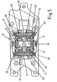
- Fig. 1 is an operating device 1, which is designed as an electrical switch in the manner of a joystick and / or cursor switch to see.
- the switch 1 has a housing 2 from which an actuator 3 for operation by the user protrudes.
- the Actuator 3 is movably mounted in the housing 2. Namely, the actuator 3 by moving in accordance with the arrows 4 in south-north direction and the arrows 5 in the east-west direction in the manner of a wind rose actuated, as well as on the basis of Fig. 2 can be seen. Further, the actuator 3 can be operated by rotating according to the double arrow 6. Finally, the actuator 3 is still movable by pressing the arrow 7, as in Fig. 3 is shown.
- the switch 1 is used for example in the motor vehicle for operating a navigation system.
- the respective inputs for the navigation system can be made by the user by appropriate movement or actuation of the actuator 3.
- the control device 1 may have further located in the housing 2 actuators 21 for electrical switches for direct selection of various other functions.
- the representation of a specific menu for the navigation system can be selected on a screen in the motor vehicle.
- the actuator 3 cooperates with a displacement means 8 such that the actuating member 3 is displaceable in a displacement plane in at least one direction 4 from a neutral position into a sliding position.
- the sliding position is formed as a switching position, such that the actuating member 3 in the switching position on a switching element not further shown switching acting, so as to generate a corresponding switching signal for the shift position.
- the displacement means 8 comprises a sliding member 19 and a guide bracket 10.
- the sliding member 19, the actuator 3 is arranged.
- the actuating member 3 is in operative connection with the sliding component 19 via further components, in order to allow further functionalities in addition to the sliding movement.
- a further functionality may be the turning of the actuating member 3, as will be explained in more detail below.
- the sliding member 19 is displaceably mounted on the guide bracket 10 by means of a ball bearing 9.
- the guide carrier 10 is arranged on an inner support 11, as shown in FIG Fig. 5 can be seen.
- the guide carrier 10 is mounted on two opposite bearing points 22 in the inner support 11.
- two guide carriers 10 are arranged parallel to one another on the inner support 11.
- the sliding member 19 is thus on the ball bearing 9 on the guide bracket 10 in a first direction 4, in the direction north-south, relative to the inner support 11 slidably.
- the displacement means 8 comprises a further guide support 10 ', as in FIG Fig. 4 you can see.
- the inner support 11 is slidably mounted by means of a ball bearing 9 on the other guide support 10 '.
- the further guide carrier 10 ' is in turn arranged on an outer carrier 12, the further guide carrier 10' is in turn mounted on two opposite bearing points 22 'in the outer carrier 12.
- the precise guide half are also two guide support 10 'arranged parallel to each other on the outer support 12.
- the inner support 11 is displaceable together with the sliding member 19 in a second direction 5, in the direction east-west, relative to the outer support 12, so that consequently the actuating member 3 is displaceable in a further displacement plane from the neutral position to a further sliding position ,
- the first direction 4 corresponding north-south and the second direction 5 corresponding east-west are substantially perpendicular to each other in the manner of a wind rose.
- the ball guide comprises according to Fig. 3 or Fig. 4
- the ball cage 23 for the guide carrier 10 is arranged on the sliding member 19 and the ball cage 23 for the further guide bracket 10 'on the inner support 11.
- a rotating means 13 is provided for the actuating member 3, such that the actuating member 3 with respect to the sliding member 19 is rotatable.
- the actuator 3 can be rotated by at least one angle from an initial position in at least one rotational position, wherein the rotational position is in turn formed as a switch element having a switching position.
- the actuator 3 is infinitely rotatable, wherein when turning the actuator 3 in Direction 6 corresponding signals are generated in the manner of switching signals of a rotary encoder.
- a photocell 24 is located, as in Fig. 3 can be seen, with the photocell 24 a rotatable means 13 located on the sprocket 26 cooperates.
- the rotating means 13 further comprises a ball bearing 14 for rotatable mounting on the sliding member 19th
- the actuator 3 is linearly movable by at least a distance from a zero position to an actuating position approximately perpendicular to the displacement plane with respect to the sliding member 19 by pressing in the direction 7.
- the actuating position is also formed as a switching element 27 having a switching position for generating a switching signal. This switching signal can be used, for example, as an enter signal.
- the further displacement means 15 comprises the guide member 18 which is displaceably arranged on the sliding component 19.
- the ball bearing 14 for the rotation means 13 is in turn arranged on the guide member 18.
- switching element 27 is actuated by cooperation with the sliding member 19.
- the switching element 27 is designed as a Kurzhubtaste and thus simultaneously causes the feel for the user.
- the switching element for the rotational movement consists, as already mentioned, of a light barrier 24.
- the switching elements for the sliding movement in east-west and south-north direction also consist of light barriers not shown.
- the switching elements for the generation of the switching signal in the switching position in any way from a photocell, an electrical contact element in the manner of a Kurzhubtaste or a Wegtendom, from a sensor o. The like. consist.
- the haptic for the sliding movement is generated by means of a switching element 16 in the manner of a Kurzhubtaste or a Heidelbergmattendoms, as in Fig. 6 you can see. If desired, however, the switching elements 16 can also be used for generating the switching signal for the displacement movement, so that it is possible to dispense with other switching elements.
- the feel for the sliding movement can also be generated by means of a magnet system 17, as in Fig. 7 can be seen closer.
- the Enter wave 19 is mounted on two parallel guide pins 10, 10 and two ball cages 23 in the inner support 11, as the Fig. 5 can be seen.
- This storage system results in a play-free but also very low-friction storage of the sliding mechanism.
- the escape shaft 19 shifts over the guide pins 10, 10, in this case for the north or south direction, and triggers the switching signal via a light barrier system. So that a collision-free movement is given, the take-off shaft 19 has Fig. 6 sufficient clearance 30 through corresponding recesses on the inner support 11 and rests exclusively on the switching elements 16.
- the haptic is generated via a switching element 16, in this case via a switching mat dome or a short-stroke key, as in FIG Fig. 6 you can see.
- the switching element 16 is pressed and forms the feel for the sliding movement.
- a magnet system 17 can be used for Haptikerzeugung, which in Fig. 7 is shown.
- the switching element 16 for this sliding direction is according to Fig. 4 and 6 stored in the inner support 11 and is actuated via the discharge shaft 19.
- the guide pins 10 in the inner support 11, on which the shooter shaft 19 is mounted via the ball cages 23, are used (for this direction, the guide pins 10 are fixedly mounted in the discharge shaft 19). that transmit force to the inner support 11, as you can see from Fig. 3 .
- Fig. 4 and Fig. 5 sees.
- the entire push-turn-slide unit shifts in the east or west direction (see also Fig. 6 ).
- the inner support 11 is also mounted on two parallel guide pins 10 'and ball cages 23 in the outer support 12 and this in turn in the base 20.
- the inner support 11 shifts due to the fixed in east-west direction storage of the guide pins 10 in the return shaft 19 on the guide pins 10 ', so that the entire push-turn sliding Unit is moved in east or west direction (see also Fig. 6 ).
- the signal is also detected by a light barrier system.
- the haptic is also generated here by means of a switching element 16, in this case a switching mat or a Kurzhubtaster stored in the base 20, as based on Fig. 3 or Fig. 6 can be seen.
- a switching element 16 in this case a switching mat or a Kurzhubtaster stored in the base 20, as based on Fig. 3 or Fig. 6 can be seen.
- To ensure a collision-free function is according to Fig. 6 for the movable push-turn-slide unit including inner support 11 in the base 20 sufficient clearance 30 'is provided.
- the inner support 11 rests exclusively on the switching elements 16, as based on the Fig. 6 can be seen.
- the rotatable unit and the unit that fulfills the push function are seated accordingly Fig. 3 and Fig. 4 on the take-off shaft 19, whereby they are decoupled from the sliding mechanism.
- the rotary and the push mechanism make the sliding movement with.
- the switching and the haptic generation of the push mechanism are realized via a Kurzhubtaster 27 connected to a circuit board 25 in the knob 3, as the Fig. 3 and the Fig. 4 can be removed.
- the switching signal for the rotating unit is according to Fig. 3 generated by means of a light barrier 24 on the circuit board 25 in the knob 3.
- the haptic generation of the rotating unit is according to Fig. 3 and Fig. 4 via a leaf spring 28, connected to the pivot bearing 13, and a trained on the guide member 18 link 29 generated.
- Such a multi-function switch can be used for car radios, for navigation systems and / or for control devices, displays o. The like. In motor vehicles.
- the invention is not limited to the described and illustrated embodiment. Rather, it also encompasses all expert developments within the scope of the invention defined by the claims.
- such a multi-function switch can also be advantageously used as input means for computers, machine tools, household appliances or the like.
- the invention can be used not only in the multi-function switches described but also in such switches, in which the actuating member is configured only displaceable.
Landscapes
- Switches With Compound Operations (AREA)
Description
Die Erfindung betrifft eine Bedienvorrichtung nach dem Oberbegriff des Patentanspruchs 1.The invention relates to an operating device according to the preamble of patent claim 1.
In der Art eines Joystick- und/oder Cursor-Schalters ausgebildete elektrische Schalter dienen als Bedienvorrichtungen zur Eingabe von Daten für ein elektrisches Gerät durch einen Benutzer. Beispielsweise werden solche Schalter für Autoradios, Navigationsgeräte, Bordcomputer oder auch zur Steuerung sonstiger Funktionen in Kraftfahrzeugen verwendet. Insbesondere läßt sich ein solcher elektrischer Schalter auch als Multifunktionsschalter zur Menüsteuerung von Funktionen über ein Display im Kraftfahrzeug verwenden.Electric switches formed in the manner of a joystick and / or cursor switch serve as operating devices for inputting data for an electrical appliance by a user. For example, such switches are used for car radios, navigation devices, on-board computers or for controlling other functions in motor vehicles. In particular, such an electrical switch can also be used as a multi-function switch for menu control of functions via a display in the motor vehicle.
Eine derartige, aus der
Der Erfindung liegt die Aufgabe zugrunde, die Bedienvorrichtung derart weiterzuentwickeln, dass die Präzision für die Verschiebebewegung gesteigert ist. Insbesondere soll ein Eingabegerät entwickelt werden, durch das es möglich ist, eine Dreh- und/oder Drück- und/oder Schiebefunktion in einen Schalter möglichst spielfrei zu integrieren. Das Eingabegerät kann zum Beispiel eine zentrale Bedieneinheit (ZBE), insbesondere für ein Kraftfahrzeug, sein. Dabei sollen insbesondere folgende Punkte konstruktiv berücksichtigt werden:
- Günstige Lösung.
- Geringe Anzahl von Bauteilen.
- Entkopplung der einzelnen Mechanismen.
- Hohe Verschleißfestigkeit der Haptikgebenden Elemente.
- Geringe Baugröße.
- Cheap solution.
- Low number of components.
- Decoupling of the individual mechanisms.
- High wear resistance of haptic-giving elements.
- Small size.
Diese Aufgabe wird bei einer gattungsgemäßen Bedienvorrichtung durch die kennzeichnenden Merkmale des Anspruchs 1 gelöst.This object is achieved in a generic operating device by the characterizing features of claim 1.
Bei der erfindungsgemäßen Bedienvorrichtung ist der Führungsträger an einem Innenträger angeordnet. Es bietet sich der Stabilität halber an, den Führungsträger an zwei einander gegenüberliegenden Lagerstellen im Innenträger gelagert anzuordnen. Insbesondere kann der Führungsträger in der Art eines Führungsbolzens, einer Führungsstange, eines Führungsstiftes o. dgl, ausgestaltet sein. Das Schiebebauteil ist somit in kompakter Art und Weise auf dem Innenträger angeordnet und in eine erste Richtung gegenüber dem Innenträger verschiebbar. Als Kugellagerung ist eine lineare Kugelführung vorgesehen. Vorteilhafterweise wird dem Benutzer somit eine präzise und/oder spielfreie Bedienung der Bedienvorrichtung geboten und es ist auch eine zuverlässige Betätigung des Schalters gewährleistet. Weitere Ausgestaltungen der Erfindung sind Gegenstand der Unteransprüche.In the operating device according to the invention, the guide carrier is arranged on an inner support. It is advisable for the sake of stability to arrange the guide carrier mounted on two opposite bearing points in the inner support. In particular, the guide carrier may be configured in the manner of a guide pin, a guide rod, a guide pin or the like. The sliding member is thus arranged in a compact manner on the inner support and displaceable in a first direction relative to the inner support. As a ball bearing a linear ball guide is provided. Advantageously, the user is thus offered a precise and / or play-free operation of the operating device and it is also a reliable operation of the switch guaranteed. Further embodiments of the invention are the subject of the dependent claims.
Zur Erweiterung der Funktionalität der Bedienvorrichtung kann das Betätigungsorgan zusätzlich in einer weiteren Verschiebeebene aus der neutralen Stellung in eine weitere Schiebestellung verschiebbar sein. Zweckmäßigerweise kann hierzu das Verschiebemittel einen weiteren Führungsträger umfassen. Der Innenträger kann wiederum mittels einer Kugellagerung am weiteren Führungsträger verschiebbar gelagert sein, so dass eine präzise sowie spielfreie Verstellung auch in die weitere Schiebestellung erzielt ist.To extend the functionality of the operating device, the actuating member may additionally be displaceable in a further displacement plane from the neutral position into a further sliding position. Conveniently, for this purpose, the displacement means comprise a further guide carrier. The inner support can in turn be mounted displaceably by means of a ball bearing on the other guide support, so that a precise and play-free adjustment is achieved in the further sliding position.
In platzsparender Ausgestaltung kann der weitere Führungsträger an einem Außenträger angeordnet sein. Zwecks guter Stabilität kann der weitere Führungsträger an zwei einander gegenüberliegenden Lagerstellen im Außenträger gelagert sein. Dadurch ist der Innenträger, und zwar insbesondere gemeinsam mit dem Schiebebauteil, in eine zweite Richtung gegenüber dem Außenträger verschiebbar. Bevorzugterweise ist die Anordnung der Führungsträger dabei derart, dass die erste sowie die zweite Richtung im Wesentlichen senkrecht aufeinander stehen. Insbesondere kann dann das Betätigungsorgan in der Art einer Windrose vom Benutzer bewegbar sein.In space-saving configuration, the further guide carrier can be arranged on an outer support. For the purpose of good stability, the further guide carrier may be mounted on two opposite bearing points in the outer carrier. As a result, the inner carrier, in particular together with the sliding member, in a second direction relative to the outer carrier displaceable. Preferably, the arrangement of the guide carrier is such that the first and the second direction are substantially perpendicular to each other. In particular, then the actuator in the manner of a wind rose can be moved by the user.
In einer bevorzugten Ausgestaltung, die sich durch besondere Einfachheit sowie auch Präzision auszeichnet, kann die Kugelführung in einem Kugelkäfig befindliche Kugeln umfassen, womit eine einfache Montage der Kugellagerung gegeben ist. Der Kugelkäfig für den Führungsträger kann in kompakter Art am Schiebebauteil und/oder der Kugelkäfig für den weiteren Führungsträger am Innenträger angeordnet sein.In a preferred embodiment, which is characterized by particular simplicity as well as precision, the ball guide may comprise balls located in a ball cage, whereby a simple assembly of the ball bearing is given. The ball cage for the guide carrier can be arranged in a compact manner on the sliding member and / or the ball cage for the further guide carrier on the inner support.
Im Hinblick auf die Präzision und/oder Stabilität der Führung bietet es sich an, dass jeweils zwei Führungsträger sowie zwei weitere Führungsträger jeweils parallel zueinander angeordnet sind. Bevorzugterweise weist dann in einer einfachen Ausgestaltung das Verschiebemittel einen Innenträger mit in je einem Kugelkäfig befindlichen Führungsträgern sowie einen Außenträger mit in je einem Kugelkäfig befindlichen weiteren Führungsträger auf.With regard to the precision and / or stability of the guide, it is advisable that two guide carriers and two further guide carriers are each arranged parallel to one another. Preferably, then in a simple embodiment, the displacement means on an inner support with each located in a ball cage guide carriers and an outer support with each located in a ball cage further guide carrier.
Insbesondere ist durch die Erfindung ein Dreh- und/oder Drück-und/oder Schiebesteller mit Kugelkäfigen zur Lagerung und/oder Führung in horizontaler Richtung geschaffen.In particular, the invention provides a rotary and / or push and / or sliding plate with ball cages for storage and / or guidance in the horizontal direction.
Ebenfalls zur Erweiterung der Funktionalität des Schalters kann ein Drehmittel für das Betätigungsorgan vorgesehen sein, so dass das Betätigungsorgan in Bezug auf das Schiebebauteil drehbar ist. Dabei kann das Betätigungsorgan bei Drehung durch den Benutzer mit einem Schaltelement zur Erzeugung eines Schaltsignals zusammenwirken. Zwecks Leichtgängigkeit der Drehbewegung kann es sich anbieten, dass das Drehmittel ein Kugellager zur drehbaren Lagerung am Schiebebauteil umfasst.Also, to extend the functionality of the switch, a rotating means may be provided for the actuator, so that the actuator is rotatable with respect to the sliding member. The actuator can rotate through the Users interact with a switching element to generate a switching signal. For ease of rotation, it may be appropriate that the rotating means comprises a ball bearing for rotatable mounting on the sliding member.
Desweiteren kann für eine nochmals erweiterte Funktionalität ein weiteres Verschiebemittel für das Betätigungsorgan vorgesehen sein, derart dass das Betätigungsorgan um wenigstens eine Strecke aus einer Nullstellung in eine Betätigungsstellung in etwa senkrecht zur Verschiebeebene in Bezug auf das Schiebebauteil linear bewegbar ist. Die Betätigungsstellung kann wiederum als eine ein Schaltelement aufweisende Schaltstellung zur Erzeugung eines Schaltsignals ausgebildet sein, so dass das Betätigungsorgan weiterhin eine Art "Enter"-Betätigung für den Benutzer gestattet.Furthermore, a further displacement means for the actuator may be provided for a further extended functionality, such that the actuator is linearly movable by at least a distance from a zero position to an actuating position approximately perpendicular to the displacement plane with respect to the sliding member. The actuating position can in turn be designed as a switching element having a switching position for generating a switching signal, so that the actuator further allows a kind of "Enter" operation for the user.
In kompakter Ausgestaltung kann das weitere Verschiebemittel ein verschiebbar am Schiebebauteil angeordnetes Führungsteil umfassen. Zweckmäßigerweise kann das Kugellager für das Drehmittel am Führungsteil angeordnet sein. Der gesteigerten Ergonomie für den Benutzer halber kann eine Blattfeder mit dem Betätigungsorgan sowie mit einer Kulisse am Führungsteil zur Erzeugung einer Haptik für die Drehbewegung in Wirkverbindung stehen.In a compact embodiment, the further displacement means may comprise a guide member arranged displaceably on the sliding component. Conveniently, the ball bearing can be arranged for the rotating means on the guide part. The increased ergonomics for the user can be a leaf spring with the actuator and a gate on the guide part to produce a feel for the rotational movement in operative connection.
In kostengünstiger weiterer Ausgestaltung kann das Schaltelement für die Erzeugung eines Schaltsignals, wobei das Schaltsignal insbesondere in der jeweiligen Schaltstellung des Betätigungsorgans erzeugt wird, aus einer Lichtschranke, einem elektrischen Kontaktelement in der Art einer Kurzhubtaste oder eines Schaltmattendoms, aus einem Sensor o. dgl. bestehen. Die Haptik für die Verschiebebewegung lässt sich in einfacher Art und Weise mittels eines Schaltelements in der Art einer Kurzhubtaste oder eines Schaltmattendoms erzeugen. Die Haptik für die Verschiebebewegung kann auch mittels eines Magnetsystems erzeugt werden. Gegebenenfalls kann auch eine ansteuerbare Haptik mittels eines Elektromotors, eines Elektromagneten o. dgl. vorgesehen sein.In a cost-effective further embodiment, the switching element for the generation of a switching signal, wherein the switching signal is generated in particular in the respective switching position of the actuator from a light barrier, an electrical contact element in the manner of a Kurzhubtaste or a Schaltmattendoms from a sensor o. The like. Exist , The haptic for the sliding movement can be generated in a simple manner by means of a switching element in the manner of a short-stroke key or a switching mat dome. The haptic for the displacement movement can also be generated by means of a magnet system. Optionally, a controllable feel by means of an electric motor, an electromagnet o. The like. Be provided.
Die mit der Erfindung erzielten Vorteile bestehen insbesondere darin, dass durch die Ausführung des Verschiebemittels mit Kugellagerung, und zwar insbesondere mit Kugelkäfigen, eine spielfreie und/oder reibungsarme Lagerung für das Betätigungsorgan der Bedienvorrichtung geschaffen ist. An weiteren Vorteilen sind noch zu nennen:
- Bessere Abstimmung der Haptik.
- Gute Entkopplung aller Funktionsrichtungen.
- Kompakte Bauweise.
- Geringe Baugröße (speziell in Z-Richtung, also in der Höhe der Bedienvorrichtung).
- Better matching of the feel.
- Good decoupling of all functional directions.
- Compact design.
- Small size (especially in the Z direction, ie at the height of the operating device).
Ein Ausführungsbeispiel der Erfindung mit verschiedenen Weiterbildungen und Ausgestaltungen ist in den Zeichnungen dargestellt und wird im folgenden näher beschrieben. Es zeigen
- Fig. 1
- einen durch Schieben, Drücken und Drehen betätigbaren elektrischen Schalter in der Art eines Multifunktionsschalters bzw. eine als zentrale Bedieneinheit im Kraftfahrzeug dienende Bedienvorrichtung in perspektivischer Ansicht,
- Fig. 2
- die Bedienvorrichtung aus
Fig. 1 in Draufsicht, wobei die Oberseite des Gehäuses geöffnet dargestellt ist, - Fig. 3
- einen Schnitt entlang der Linie 3-3 (Schiebeachse Süd-Nord) in
Fig. 2 , - Fig. 4
- einen Schnitt entlang der Linie 4-4 (Schiebeachse Ost-West) in
Fig. 2 , - Fig. 5
- einen Schnitt entlang der Linie 5-5 (Schiebemechanik) in
Fig. 4 , - Fig. 6
- einen vergrößerten Ausschnitt aus
Fig. 5 zur näheren Ausgestaltung der Schiebemechanik der Bedienvorrichtung und - Fig. 7
- einen Schnitt wie in
Fig. 3 gemäß einer anderen Ausgestaltung.
- Fig. 1
- an actuatable by sliding, pushing and turning electrical switch in the manner of a multi-function switch or serving as a central control unit in the motor vehicle operating device in a perspective view,
- Fig. 2
- the operating device off
Fig. 1 in plan view, wherein the top of the housing is shown open, - Fig. 3
- a section along the line 3-3 (sliding axis south-north) in
Fig. 2 . - Fig. 4
- a section along the line 4-4 (sliding axis east-west) in
Fig. 2 . - Fig. 5
- a section along the line 5-5 (sliding mechanism) in
Fig. 4 . - Fig. 6
- an enlarged section
Fig. 5 for further development of the sliding mechanism of the operating device and - Fig. 7
- a cut like in
Fig. 3 according to another embodiment.
In
Der Schalter 1 dient beispielsweise im Kraftfahrzeug zur Bedienung eines Navigationssystems. Die jeweiligen Eingaben für das Navigationssystem können vom Benutzer durch entsprechende Bewegung bzw. Betätigung des Betätigungsorgans 3 vorgenommen werden. Wie man weiter der
Wie man anhand der
Wie in
Der Führungsträger 10 ist an einem Innenträger 11 angeordnet, wie anhand der
Das Verschiebemittel 8 umfasst einen weiteren Führungsträger 10', wie in
Die erste Richtung 4 entsprechend Nord-Süd sowie die zweite Richtung 5 entsprechend Ost-West stehen im wesentlichen senkrecht in der Art einer Windrose aufeinander.The displacement means 8 comprises a further guide support 10 ', as in FIG
The
Wie man weiter der
Gemäß
Schließlich ist noch ein weiteres Verschiebemittel 15 für das Betätigungsorgan 3 vorgesehen, derart dass das Betätigungsorgan 3 um wenigstens eine Strecke aus einer Nullstellung in eine Betätigungsstellung in etwa senkrecht zur Verschiebeebene in Bezug auf das Schiebebauteil 19 durch Drücken in Richtung 7 linear bewegbar ist. Wie anhand von
Das weitere Verschiebemittel 15 umfasst das verschiebbar am Schiebebauteil 19 angeordnete Führungsteil 18. Das Kugellager 14 für das Drehmittel 13 ist wiederum am Führungsteil 18 angeordnet. Beim Drücken in Richtung 7 auf das Betätigungsorgan 3 wird somit das Drehmittel 13 ebenfalls mit verschoben. Gleichzeitig wird das auf der Leiterplatte 25 befindliche Schaltelement 27 durch Zusammenwirken mit dem Schiebebauteil 19 betätigt. Das Schaltelement 27 ist als eine Kurzhubtaste ausgebildet und bewirkt somit gleichzeitig die Haptik für den Benutzer. Schließlich steht noch eine Blattfeder 28 mit dem Betätigungsorgan 3, und zwar mit der Drehlagerung 13, sowie mit einer Kulisse 29 am Führungsteil 18 zur Erzeugung einer Haptik für die Drehbewegung in Wirkverbindung.The further displacement means 15 comprises the
Das Schaltelement für die Drehbewegung besteht, wie bereits erwähnt, aus einer Lichtschranke 24. Die Schaltelemente für die Schiebebewegung in Ost-West- sowie in Süd-Nord-Richtung bestehen ebenfalls aus nicht weiter gezeigten Lichtschranken. Das Schaltelement für die Drückbewegung besteht aus einer Kurzhubtaste 27. Selbstverständlich können die Schaltelemente für die Erzeugung des Schaltsignals in der Schaltstellung jedoch in beliebiger Weise aus einer Lichtschranke, einem elektrischen Kontaktelement in der Art einer Kurzhubtaste oder einem Schaltmattendom, aus einem Sensor o. dgl. bestehen.The switching element for the rotational movement consists, as already mentioned, of a
Die Haptik für die Verschiebebewegung wird mittels eines Schaltelements 16 in der Art einer Kurzhubtaste oder eines Schaltmattendoms erzeugt, wie in
Geschaffen ist beim erfindungsgemäßen Schalter 1 die Umsetzung einer Lösung für vier Schieberichtungen 4, 5, also für zwei Funktionsebenen, über je zwei parallel angeordnete Führungsträger 10, 10' mit Kugellagerung 9 je Schieberichtung 4,5. Die Wirkungsweise des elektrischen Schalters 1 soll nachfolgend näher erläutert werden.Created at the switch 1 according to the invention, the implementation of a solution for four sliding
Funktionsweise für die Schiebebewegung:
- Gemäß
Fig. 3 undFig. 4 wird die Schiebebewegungdurch das Betätigungsorgan 3, nachfolgend auch Drehknopf 3 genannt, eingeleitet.Der Drehknopf 3 sitzt auf der Drehlagerung 13, welche mittels eines Kugellagers 14mit dem Führungsteil 18 verbunden ist.Über das Führungsteil 18 wird die Schiebebewegung dann andas Schiebebauteil 19, nachfolgend auch Enterwelle 19 genannt, weitergegeben.
- According to
Fig. 3 andFig. 4 is the sliding movement by theactuator 3, hereinafter also calledrotary knob 3, initiated. Theknob 3 is seated on the pivot bearing 13, which is connected by means of aball bearing 14 with theguide member 18. About theguide member 18, the sliding movement is then passed to the slidingmember 19, hereinafter also calledenter shaft 19, passed.
Die Enterwelle 19 ist über zwei parallel angeordnete Führungsstifte 10, 10 und zwei Kugelkäfige 23 in dem Innenträger 11 gelagert, wie der
Wird der Drehknopf 3 nun in Ost-West-Richtung ausgelenkt, so wird über die Führungsstifte 10 im Innenträger 11, auf denen die Enterwelle 19 über die Kugelkäfige 23 gelagert ist (für diese Richtung sind die Führungsstifte 10 in der Enterwelle (19 fest gelagert), die Kraft auf den Innenträger 11 übertragen, wie man anhand von
Wie bereits erwähnt, ist in
Die drehbare Einheit und die Einheit, welche die Drückfunktion erfüllt, sitzen gemäß
Durch die Anordnung der parallel geführten Führungselemente 10, 10', die sich alle auf einer Höhe befinden, ist ein sehr geringer Bauraum für den Schalter 1 umsetzbar.The arrangement of the parallel guided
Ein derartiger Mehrfunktionsschalter lässt sich für Autoradios, für Navigationssysteme und/oder für Steuergeräte, Displays o. dgl. in Kraftfahrzeugen verwenden. Die Erfindung ist jedoch nicht auf das beschriebene und dargestellte Ausführungsbeispiel beschränkt. Sie umfasst vielmehr auch alle fachmännischen Weiterbildungen im Rahmen der durch die Patentansprüche definierten Erfindung. Neben Kraftfahrzeuganwendungen kann ein derartiger Mehrfunktionsschalter in vorteilhafter Weise auch als Eingabemittel für Computer, Werkzeugmaschinen, Haushaltsgeräte o. dgl. eingesetzt werden. Schließlich lässt sich die Erfindung nicht nur bei den beschriebenen Multifunktionsschaltern sondern auch bei solchen Schaltern einsetzen, bei denen das Betätigungsorgan lediglich verschiebbar ausgestaltet ist.Such a multi-function switch can be used for car radios, for navigation systems and / or for control devices, displays o. The like. In motor vehicles. However, the invention is not limited to the described and illustrated embodiment. Rather, it also encompasses all expert developments within the scope of the invention defined by the claims. In addition to automotive applications, such a multi-function switch can also be advantageously used as input means for computers, machine tools, household appliances or the like. Finally, the invention can be used not only in the multi-function switches described but also in such switches, in which the actuating member is configured only displaceable.
- 1:1:
- Bedienvorrichtung / (elektrischer) SchalterControl device / (electrical) switch
- 2:2:
- Gehäusecasing
- 3:3:
- Betätigungsorgan / DrehknopfActuator / knob
- 4,5:4,5:
- Pfeil (Verschieben) / Richtung / SchieberichtungArrow (move) / direction / sliding direction
- 6:6:
- Doppelpfeil (Drehen) / RichtungDouble arrow (turning) / direction
- 7:7:
- Pfeil (Drücken) / RichtungArrow (push) / direction
- 8:8th:
- Verschiebemitteldisplacement means
- 9:9:
- Kugellagerung / KugelBall bearing / ball
- 10:10:
- Führungsträger / Führungsstift / FührungselementGuide carrier / guide pin / guide element
- 10':10 ':
- (weiterer) Führungsträger / Führungsstift / Führungselement(further) leadership / leadership / leadership
- 11:11:
- Innenträgerinternal support
- 12:12:
- Außenträgerbalconnet
- 13:13:
- Drehmittel / DrehlagerungTurning means / rotary bearing
- 14:14:
- Kugellagerball-bearing
- 15:15:
- (weiteres) Verschiebemittel(further) displacement means
- 16:16:
- Schaltelement (für Haptik)Switching element (for haptics)
- 17:17:
- Magnetsystem (für Haptik)Magnet system (for haptics)
- 18:18:
- Führungsteilguide part
- 19:19:
- Schiebebauteil / EnterwelleSliding component / Enter wave
- 20:20:
- Sockelbase
- 21:21:
- Betätigungselementjig
- 22,22':22.22 ':
- Lagerstelle (für Führungsträger)Depository (for executives)
- 23:23:
- Kugelkäfigball cage
- 24:24:
- Lichtschranke / SchaltelementPhotocell / switching element
- 25:25:
- Leiterplattecircuit board
- 26:26:
- Zahnkranzsprocket
- 27:27:
- Schaltelement / Kurzhubtaste / KurzhubtasterSwitching element / short-stroke button / short-stroke button
- 28:28:
- Blattfederleaf spring
- 29:29:
- Kulissescenery
- 30,30':30.30 ':
- Freiraumfree space
Claims (13)
- An operating device, in particular an electrical switch of a joystick or cursor-switch type, comprising a movable actuation member (3), wherein the actuation member (3) cooperates with a displacing means (8) in such a manner that the actuating member (3) can be displaced in at least one direction (4, 5) in a displacement plane, from a neutral position into a shifted position, wherein the shifted position is designed as a switching position, in such a manner that the actuating member (3) acts in a switching manner on a switching element in the switching position in order to generate a switching signal, wherein the displacing means (8) comprises a shifting component (19), on which the actuating member (3) is arranged and/or which is in operative connection with the actuating member (3), and a guide carrier (10), and wherein the shifting component (19) is mounted in a displaceable manner by means of a ball bearing (9) on the guide carrier (10), characterised in that the guide carrier (10) is mounted on two opposite lying mounting points (22) on an inner carrier (11), such that the shifting component (19) can be displaced in a first direction (4) with respect to the inner carrier (11), and in that a linear ball guide is provided as the ball bearing (9).
- The operating device according to claim 1, characterised in that the actuation member (3) can be displaced in a further displacement plane from the neutral position into a further shifted position, and in that the displacing means (8) comprises a further guide carrier (10'), wherein the inner carrier (11) is displaceably mounted by means of a ball bearing (9) on the further guide carrier (10').
- The operating device according to claim 1 or 2, characterised in that the further guide carrier (10') is mounted on two opposite lying mounting points (22') on an outer carrier (12), such that the inner carrier (11) is displaceable together with the shifting component (19) in a second direction (5) with respect to the outer carrier (12).
- The operating device according to claim 3, characterised in that the first and the second direction (4, 5) are substantially perpendicular to one another.
- The operating device according to any one of claims 1 to 4, characterised in that the ball guide comprises balls (9) in a ball cage (23), in that the ball cage (23) for the guide carrier (10) is arranged on the shifting component (19), and in that the ball cage (23) for the further guide carrier (10') is arranged on the inner carrier (11).
- The operating device according to any one of claims 1 to 5, characterised in that a rotation means (13) is provided for the actuation member (3), such that the actuation member (3) can be rotated with respect to the shifting component (19), and such that during rotation the actuation member (3) interacts with a switch element (24) to generate a switching signal.
- The operating device according to claim 6, characterised in that the rotation means (13) comprises a ball bearing (14) for rotary mounting on the shifting component (19).
- The operating device according to any one of claims 1 to 7, characterised in that a further displacing means (15) is provided for the actuation member (3), in such a way that the actuation member (3) is linearly displaceable relative to the shifting component (19) approximately perpendicular to the displacement plane, about at least one stretch from a zero position into an actuation position, and in that the actuation position is designed as a switching position comprising a switching element (27) for generating a switching signal.
- The operating device according to any one of claims 1 to 8, characterised in that the further displacing means (15) comprise a guide part (18) displaceably arranged on the shifting component (19).
- The operating device according to claim 9, characterised in that the ball bearing (14) is arranged on the guide part (18) for the rotation means (13).
- The operating device according to claim 9 or 10, characterised in that a leaf spring (28) is operatively connected to the actuation member (3) as well as to a link (29) on the guide part (18), in order to create a feel for the rotary movement.
- The operating device according to any one of claims 1 to 11, characterised in that the switching element for the generation of a switching signal consists of a light barrier (24), an electrical contact element, a short-stroke button (27), a switching mat dome or a sensor.
- The operating device according to any one of claims 1 to 12, characterised in that the feel for the shifting movement is generated by means of a switching element (16), a short-stroke button, a switching mat dome or by means of a magnet system (17).
Applications Claiming Priority (2)
| Application Number | Priority Date | Filing Date | Title |
|---|---|---|---|
| DE102012010591 | 2012-05-30 | ||
| PCT/EP2013/001583 WO2013178357A1 (en) | 2012-05-30 | 2013-05-29 | Operating device, particularly of an electrical switch type |
Publications (2)
| Publication Number | Publication Date |
|---|---|
| EP2856485A1 EP2856485A1 (en) | 2015-04-08 |
| EP2856485B1 true EP2856485B1 (en) | 2018-04-11 |
Family
ID=48607200
Family Applications (1)
| Application Number | Title | Priority Date | Filing Date |
|---|---|---|---|
| EP13728111.9A Not-in-force EP2856485B1 (en) | 2012-05-30 | 2013-05-29 | Operating device, particularly of an electrical switch type |
Country Status (4)
| Country | Link |
|---|---|
| EP (1) | EP2856485B1 (en) |
| DE (1) | DE102013008972A1 (en) |
| ES (1) | ES2675276T3 (en) |
| WO (1) | WO2013178357A1 (en) |
Families Citing this family (5)
| Publication number | Priority date | Publication date | Assignee | Title |
|---|---|---|---|---|
| DE102015107992B4 (en) * | 2015-05-20 | 2017-11-02 | Preh Gmbh | Control element with turntable and shift functionality |
| US11397108B2 (en) | 2015-06-16 | 2022-07-26 | Marquardt Gmbh | Multi-function controller and method of using same |
| DE102015015511B4 (en) | 2015-11-30 | 2022-03-24 | Audi Ag | Operating device for a motor vehicle and method for operating an operating device |
| US10527462B2 (en) | 2016-07-08 | 2020-01-07 | Marquardt Gmbh | Encoder and method of using the same |
| DE102019214109A1 (en) * | 2019-09-17 | 2021-03-18 | Zf Friedrichshafen Ag | Operating device, in particular for a device of a motor vehicle |
Family Cites Families (3)
| Publication number | Priority date | Publication date | Assignee | Title |
|---|---|---|---|---|
| BE1015905A6 (en) * | 2004-02-13 | 2005-11-08 | Prud Homme Francois | MULTI-TOUCH DIRECTIONS PROVIDED WITH A COCK meshing MOBILE TOWER TOWER FOUR OPENINGS FOR DESCRIBING TWENTY-EIGHT MEMORY SENSORY JOURNEYS DETECTED. |
| US7193166B2 (en) * | 2005-08-05 | 2007-03-20 | Niles Co., Ltd. | Joystic input device |
| FR2913811B1 (en) * | 2007-03-12 | 2009-05-08 | Itt Mfg Enterprises Inc | MULTIDIRECTIONAL CONTROLLER ERGONOMIC |
-
2013
- 2013-05-28 DE DE102013008972A patent/DE102013008972A1/en not_active Withdrawn
- 2013-05-29 WO PCT/EP2013/001583 patent/WO2013178357A1/en active Application Filing
- 2013-05-29 ES ES13728111.9T patent/ES2675276T3/en active Active
- 2013-05-29 EP EP13728111.9A patent/EP2856485B1/en not_active Not-in-force
Also Published As
| Publication number | Publication date |
|---|---|
| DE102013008972A1 (en) | 2013-12-05 |
| EP2856485A1 (en) | 2015-04-08 |
| ES2675276T3 (en) | 2018-07-10 |
| WO2013178357A1 (en) | 2013-12-05 |
Similar Documents
| Publication | Publication Date | Title |
|---|---|---|
| DE102011083524B4 (en) | Turn / push control device for a human-machine interface | |
| DE102009013441A1 (en) | Electric switch | |
| DE102006028228B4 (en) | Actuator for manual control of functions in a motor vehicle and electronic gear selector switch so | |
| EP1961025B1 (en) | Control button comprising integrated functionality | |
| EP2984667B1 (en) | Device for operating multiple functions in a motor vehicle | |
| EP2856485B1 (en) | Operating device, particularly of an electrical switch type | |
| DE10241869B4 (en) | Electric switch | |
| EP1621954B1 (en) | Electrical joystick | |
| EP3167209B1 (en) | Control element, in particular for a motor vehicle | |
| EP1907916B1 (en) | Operating element with a central pushbutton | |
| WO2005015592A2 (en) | Electric switch | |
| WO2014198418A1 (en) | Switching operating arrangement | |
| DE102005001560A1 (en) | Rotary actuator for electric or electronic device in motor vehicle, has linear actuator designed as lifting armature magnet and controlling engagement of ratchet in lock retainer that is connected to adjusting rings by tappet | |
| EP1215556B1 (en) | Electric switch | |
| EP1736846B1 (en) | Actuator, in particular of the electric switch type | |
| EP1705553A2 (en) | Operating device | |
| DE102012017122A1 (en) | Multifunctional electric switch e.g. joystick for e.g. car radio, has actuating arm that is acted on actuator during pivoting of actuator, so that pivotal movement of actuating arm is deflected into linear movement of actuator | |
| DE102012018910B4 (en) | Switching device for switching an electronic device of a motor vehicle | |
| DE102006028227A1 (en) | Actuator e.g. electronic gear selection switch, for motor vehicle, has handle and rotating unit working together, where break force acting on handle in rotatable position is produced by magnetic strength | |
| DE60302859T2 (en) | Actuator with a switch button that is rotatable about several axes | |
| WO2008012063A1 (en) | Multifunctional operating unit for a motor vehicle | |
| DE102012014019A1 (en) | Electrical switch i.e. gear selector switch, for use in steering wheel to select gear in gear box of motor car, has lever acting on switching element such that operation stroke is translated into function stroke to switch switching element | |
| WO2009133080A1 (en) | Operating element having an operating knob which can be pivoted about two spatial axes | |
| WO2021099126A1 (en) | Actuator, in particular for a motor vehicle | |
| EP1321954A1 (en) | Switch unit and control lever with integrated switch unit |
Legal Events
| Date | Code | Title | Description |
|---|---|---|---|
| PUAI | Public reference made under article 153(3) epc to a published international application that has entered the european phase |
Free format text: ORIGINAL CODE: 0009012 |
|
| 17P | Request for examination filed |
Effective date: 20141006 |
|
| AK | Designated contracting states |
Kind code of ref document: A1 Designated state(s): AL AT BE BG CH CY CZ DE DK EE ES FI FR GB GR HR HU IE IS IT LI LT LU LV MC MK MT NL NO PL PT RO RS SE SI SK SM TR |
|
| AX | Request for extension of the european patent |
Extension state: BA ME |
|
| DAX | Request for extension of the european patent (deleted) | ||
| GRAP | Despatch of communication of intention to grant a patent |
Free format text: ORIGINAL CODE: EPIDOSNIGR1 |
|
| INTG | Intention to grant announced |
Effective date: 20171122 |
|
| GRAS | Grant fee paid |
Free format text: ORIGINAL CODE: EPIDOSNIGR3 |
|
| GRAA | (expected) grant |
Free format text: ORIGINAL CODE: 0009210 |
|
| AK | Designated contracting states |
Kind code of ref document: B1 Designated state(s): AL AT BE BG CH CY CZ DE DK EE ES FI FR GB GR HR HU IE IS IT LI LT LU LV MC MK MT NL NO PL PT RO RS SE SI SK SM TR |
|
| REG | Reference to a national code |
Ref country code: GB Ref legal event code: FG4D Free format text: NOT ENGLISH |
|
| REG | Reference to a national code |
Ref country code: CH Ref legal event code: EP |
|
| REG | Reference to a national code |
Ref country code: AT Ref legal event code: REF Ref document number: 988855 Country of ref document: AT Kind code of ref document: T Effective date: 20180415 |
|
| REG | Reference to a national code |
Ref country code: IE Ref legal event code: FG4D Free format text: LANGUAGE OF EP DOCUMENT: GERMAN |
|
| REG | Reference to a national code |
Ref country code: DE Ref legal event code: R096 Ref document number: 502013009900 Country of ref document: DE |
|
| REG | Reference to a national code |
Ref country code: FR Ref legal event code: PLFP Year of fee payment: 6 |
|
| REG | Reference to a national code |
Ref country code: ES Ref legal event code: FG2A Ref document number: 2675276 Country of ref document: ES Kind code of ref document: T3 Effective date: 20180710 |
|
| REG | Reference to a national code |
Ref country code: NL Ref legal event code: MP Effective date: 20180411 |
|
| REG | Reference to a national code |
Ref country code: LT Ref legal event code: MG4D |
|
| PG25 | Lapsed in a contracting state [announced via postgrant information from national office to epo] |
Ref country code: NL Free format text: LAPSE BECAUSE OF FAILURE TO SUBMIT A TRANSLATION OF THE DESCRIPTION OR TO PAY THE FEE WITHIN THE PRESCRIBED TIME-LIMIT Effective date: 20180411 |
|
| PG25 | Lapsed in a contracting state [announced via postgrant information from national office to epo] |
Ref country code: FI Free format text: LAPSE BECAUSE OF FAILURE TO SUBMIT A TRANSLATION OF THE DESCRIPTION OR TO PAY THE FEE WITHIN THE PRESCRIBED TIME-LIMIT Effective date: 20180411 Ref country code: BG Free format text: LAPSE BECAUSE OF FAILURE TO SUBMIT A TRANSLATION OF THE DESCRIPTION OR TO PAY THE FEE WITHIN THE PRESCRIBED TIME-LIMIT Effective date: 20180711 Ref country code: SE Free format text: LAPSE BECAUSE OF FAILURE TO SUBMIT A TRANSLATION OF THE DESCRIPTION OR TO PAY THE FEE WITHIN THE PRESCRIBED TIME-LIMIT Effective date: 20180411 Ref country code: LT Free format text: LAPSE BECAUSE OF FAILURE TO SUBMIT A TRANSLATION OF THE DESCRIPTION OR TO PAY THE FEE WITHIN THE PRESCRIBED TIME-LIMIT Effective date: 20180411 Ref country code: NO Free format text: LAPSE BECAUSE OF FAILURE TO SUBMIT A TRANSLATION OF THE DESCRIPTION OR TO PAY THE FEE WITHIN THE PRESCRIBED TIME-LIMIT Effective date: 20180711 Ref country code: AL Free format text: LAPSE BECAUSE OF FAILURE TO SUBMIT A TRANSLATION OF THE DESCRIPTION OR TO PAY THE FEE WITHIN THE PRESCRIBED TIME-LIMIT Effective date: 20180411 Ref country code: PL Free format text: LAPSE BECAUSE OF FAILURE TO SUBMIT A TRANSLATION OF THE DESCRIPTION OR TO PAY THE FEE WITHIN THE PRESCRIBED TIME-LIMIT Effective date: 20180411 |
|
| PG25 | Lapsed in a contracting state [announced via postgrant information from national office to epo] |
Ref country code: HR Free format text: LAPSE BECAUSE OF FAILURE TO SUBMIT A TRANSLATION OF THE DESCRIPTION OR TO PAY THE FEE WITHIN THE PRESCRIBED TIME-LIMIT Effective date: 20180411 Ref country code: RS Free format text: LAPSE BECAUSE OF FAILURE TO SUBMIT A TRANSLATION OF THE DESCRIPTION OR TO PAY THE FEE WITHIN THE PRESCRIBED TIME-LIMIT Effective date: 20180411 Ref country code: LV Free format text: LAPSE BECAUSE OF FAILURE TO SUBMIT A TRANSLATION OF THE DESCRIPTION OR TO PAY THE FEE WITHIN THE PRESCRIBED TIME-LIMIT Effective date: 20180411 Ref country code: GR Free format text: LAPSE BECAUSE OF FAILURE TO SUBMIT A TRANSLATION OF THE DESCRIPTION OR TO PAY THE FEE WITHIN THE PRESCRIBED TIME-LIMIT Effective date: 20180712 |
|
| REG | Reference to a national code |
Ref country code: CH Ref legal event code: PL |
|
| PG25 | Lapsed in a contracting state [announced via postgrant information from national office to epo] |
Ref country code: PT Free format text: LAPSE BECAUSE OF FAILURE TO SUBMIT A TRANSLATION OF THE DESCRIPTION OR TO PAY THE FEE WITHIN THE PRESCRIBED TIME-LIMIT Effective date: 20180813 |
|
| REG | Reference to a national code |
Ref country code: DE Ref legal event code: R097 Ref document number: 502013009900 Country of ref document: DE |
|
| REG | Reference to a national code |
Ref country code: BE Ref legal event code: MM Effective date: 20180531 |
|
| PG25 | Lapsed in a contracting state [announced via postgrant information from national office to epo] |
Ref country code: RO Free format text: LAPSE BECAUSE OF FAILURE TO SUBMIT A TRANSLATION OF THE DESCRIPTION OR TO PAY THE FEE WITHIN THE PRESCRIBED TIME-LIMIT Effective date: 20180411 Ref country code: SK Free format text: LAPSE BECAUSE OF FAILURE TO SUBMIT A TRANSLATION OF THE DESCRIPTION OR TO PAY THE FEE WITHIN THE PRESCRIBED TIME-LIMIT Effective date: 20180411 Ref country code: CZ Free format text: LAPSE BECAUSE OF FAILURE TO SUBMIT A TRANSLATION OF THE DESCRIPTION OR TO PAY THE FEE WITHIN THE PRESCRIBED TIME-LIMIT Effective date: 20180411 Ref country code: MC Free format text: LAPSE BECAUSE OF FAILURE TO SUBMIT A TRANSLATION OF THE DESCRIPTION OR TO PAY THE FEE WITHIN THE PRESCRIBED TIME-LIMIT Effective date: 20180411 Ref country code: EE Free format text: LAPSE BECAUSE OF FAILURE TO SUBMIT A TRANSLATION OF THE DESCRIPTION OR TO PAY THE FEE WITHIN THE PRESCRIBED TIME-LIMIT Effective date: 20180411 Ref country code: DK Free format text: LAPSE BECAUSE OF FAILURE TO SUBMIT A TRANSLATION OF THE DESCRIPTION OR TO PAY THE FEE WITHIN THE PRESCRIBED TIME-LIMIT Effective date: 20180411 |
|
| PLBE | No opposition filed within time limit |
Free format text: ORIGINAL CODE: 0009261 |
|
| STAA | Information on the status of an ep patent application or granted ep patent |
Free format text: STATUS: NO OPPOSITION FILED WITHIN TIME LIMIT |
|
| REG | Reference to a national code |
Ref country code: IE Ref legal event code: MM4A |
|
| PG25 | Lapsed in a contracting state [announced via postgrant information from national office to epo] |
Ref country code: SM Free format text: LAPSE BECAUSE OF FAILURE TO SUBMIT A TRANSLATION OF THE DESCRIPTION OR TO PAY THE FEE WITHIN THE PRESCRIBED TIME-LIMIT Effective date: 20180411 Ref country code: CH Free format text: LAPSE BECAUSE OF NON-PAYMENT OF DUE FEES Effective date: 20180531 Ref country code: LI Free format text: LAPSE BECAUSE OF NON-PAYMENT OF DUE FEES Effective date: 20180531 |
|
| 26N | No opposition filed |
Effective date: 20190114 |
|
| PG25 | Lapsed in a contracting state [announced via postgrant information from national office to epo] |
Ref country code: LU Free format text: LAPSE BECAUSE OF NON-PAYMENT OF DUE FEES Effective date: 20180529 |
|
| PG25 | Lapsed in a contracting state [announced via postgrant information from national office to epo] |
Ref country code: IE Free format text: LAPSE BECAUSE OF NON-PAYMENT OF DUE FEES Effective date: 20180529 |
|
| PG25 | Lapsed in a contracting state [announced via postgrant information from national office to epo] |
Ref country code: SI Free format text: LAPSE BECAUSE OF FAILURE TO SUBMIT A TRANSLATION OF THE DESCRIPTION OR TO PAY THE FEE WITHIN THE PRESCRIBED TIME-LIMIT Effective date: 20180411 Ref country code: BE Free format text: LAPSE BECAUSE OF NON-PAYMENT OF DUE FEES Effective date: 20180531 |
|
| REG | Reference to a national code |
Ref country code: AT Ref legal event code: MM01 Ref document number: 988855 Country of ref document: AT Kind code of ref document: T Effective date: 20180529 |
|
| PG25 | Lapsed in a contracting state [announced via postgrant information from national office to epo] |
Ref country code: AT Free format text: LAPSE BECAUSE OF NON-PAYMENT OF DUE FEES Effective date: 20180529 |
|
| PG25 | Lapsed in a contracting state [announced via postgrant information from national office to epo] |
Ref country code: MT Free format text: LAPSE BECAUSE OF FAILURE TO SUBMIT A TRANSLATION OF THE DESCRIPTION OR TO PAY THE FEE WITHIN THE PRESCRIBED TIME-LIMIT Effective date: 20180411 |
|
| PG25 | Lapsed in a contracting state [announced via postgrant information from national office to epo] |
Ref country code: TR Free format text: LAPSE BECAUSE OF FAILURE TO SUBMIT A TRANSLATION OF THE DESCRIPTION OR TO PAY THE FEE WITHIN THE PRESCRIBED TIME-LIMIT Effective date: 20180411 |
|
| PG25 | Lapsed in a contracting state [announced via postgrant information from national office to epo] |
Ref country code: HU Free format text: LAPSE BECAUSE OF FAILURE TO SUBMIT A TRANSLATION OF THE DESCRIPTION OR TO PAY THE FEE WITHIN THE PRESCRIBED TIME-LIMIT; INVALID AB INITIO Effective date: 20130529 Ref country code: MK Free format text: LAPSE BECAUSE OF NON-PAYMENT OF DUE FEES Effective date: 20180411 Ref country code: CY Free format text: LAPSE BECAUSE OF FAILURE TO SUBMIT A TRANSLATION OF THE DESCRIPTION OR TO PAY THE FEE WITHIN THE PRESCRIBED TIME-LIMIT Effective date: 20180411 |
|
| PG25 | Lapsed in a contracting state [announced via postgrant information from national office to epo] |
Ref country code: IS Free format text: LAPSE BECAUSE OF FAILURE TO SUBMIT A TRANSLATION OF THE DESCRIPTION OR TO PAY THE FEE WITHIN THE PRESCRIBED TIME-LIMIT Effective date: 20180811 |
|
| REG | Reference to a national code |
Ref country code: DE Ref legal event code: R082 Ref document number: 502013009900 Country of ref document: DE Representative=s name: JOSTARNDT PATENTANWALTS-AG, DE |
|
| PGFP | Annual fee paid to national office [announced via postgrant information from national office to epo] |
Ref country code: FR Payment date: 20210525 Year of fee payment: 9 Ref country code: IT Payment date: 20210527 Year of fee payment: 9 Ref country code: DE Payment date: 20210531 Year of fee payment: 9 |
|
| PGFP | Annual fee paid to national office [announced via postgrant information from national office to epo] |
Ref country code: GB Payment date: 20210525 Year of fee payment: 9 |
|
| PGFP | Annual fee paid to national office [announced via postgrant information from national office to epo] |
Ref country code: ES Payment date: 20210721 Year of fee payment: 9 |
|
| REG | Reference to a national code |
Ref country code: DE Ref legal event code: R119 Ref document number: 502013009900 Country of ref document: DE |
|
| GBPC | Gb: european patent ceased through non-payment of renewal fee |
Effective date: 20220529 |
|
| PG25 | Lapsed in a contracting state [announced via postgrant information from national office to epo] |
Ref country code: FR Free format text: LAPSE BECAUSE OF NON-PAYMENT OF DUE FEES Effective date: 20220531 |
|
| PG25 | Lapsed in a contracting state [announced via postgrant information from national office to epo] |
Ref country code: GB Free format text: LAPSE BECAUSE OF NON-PAYMENT OF DUE FEES Effective date: 20220529 Ref country code: DE Free format text: LAPSE BECAUSE OF NON-PAYMENT OF DUE FEES Effective date: 20221201 |
|
| REG | Reference to a national code |
Ref country code: ES Ref legal event code: FD2A Effective date: 20230728 |
|
| PG25 | Lapsed in a contracting state [announced via postgrant information from national office to epo] |
Ref country code: IT Free format text: LAPSE BECAUSE OF NON-PAYMENT OF DUE FEES Effective date: 20220529 |
|
| PG25 | Lapsed in a contracting state [announced via postgrant information from national office to epo] |
Ref country code: ES Free format text: LAPSE BECAUSE OF NON-PAYMENT OF DUE FEES Effective date: 20220530 |