EP2853772A1 - Torsion vibration damper - Google Patents
Torsion vibration damper Download PDFInfo
- Publication number
- EP2853772A1 EP2853772A1 EP20140181711 EP14181711A EP2853772A1 EP 2853772 A1 EP2853772 A1 EP 2853772A1 EP 20140181711 EP20140181711 EP 20140181711 EP 14181711 A EP14181711 A EP 14181711A EP 2853772 A1 EP2853772 A1 EP 2853772A1
- Authority
- EP
- European Patent Office
- Prior art keywords
- damping
- absorber
- absorber mass
- unit
- vibration damper
- Prior art date
- Legal status (The legal status is an assumption and is not a legal conclusion. Google has not performed a legal analysis and makes no representation as to the accuracy of the status listed.)
- Granted
Links
- 239000006096 absorbing agent Substances 0.000 claims abstract description 266
- 238000013016 damping Methods 0.000 claims abstract description 157
- 230000008878 coupling Effects 0.000 claims description 34
- 238000010168 coupling process Methods 0.000 claims description 34
- 238000005859 coupling reaction Methods 0.000 claims description 34
- 239000000969 carrier Substances 0.000 claims description 10
- 238000002485 combustion reaction Methods 0.000 claims description 10
- 238000005096 rolling process Methods 0.000 description 13
- 125000006850 spacer group Chemical group 0.000 description 10
- 230000008029 eradication Effects 0.000 description 9
- 230000005284 excitation Effects 0.000 description 9
- 230000009849 deactivation Effects 0.000 description 6
- 230000002093 peripheral effect Effects 0.000 description 6
- 238000010521 absorption reaction Methods 0.000 description 2
- 230000006378 damage Effects 0.000 description 2
- 230000000694 effects Effects 0.000 description 2
- 238000009434 installation Methods 0.000 description 2
- 230000001360 synchronised effect Effects 0.000 description 2
- 229910000831 Steel Inorganic materials 0.000 description 1
- 230000004913 activation Effects 0.000 description 1
- 230000002146 bilateral effect Effects 0.000 description 1
- 230000005540 biological transmission Effects 0.000 description 1
- 230000015572 biosynthetic process Effects 0.000 description 1
- 230000006835 compression Effects 0.000 description 1
- 238000007906 compression Methods 0.000 description 1
- 238000010276 construction Methods 0.000 description 1
- 230000003247 decreasing effect Effects 0.000 description 1
- 230000001419 dependent effect Effects 0.000 description 1
- 229910052751 metal Inorganic materials 0.000 description 1
- 238000000465 moulding Methods 0.000 description 1
- 230000010355 oscillation Effects 0.000 description 1
- 230000001846 repelling effect Effects 0.000 description 1
- 239000007787 solid Substances 0.000 description 1
- 239000010959 steel Substances 0.000 description 1
- 238000011144 upstream manufacturing Methods 0.000 description 1
- 238000003466 welding Methods 0.000 description 1
Images

Classifications
-
- F—MECHANICAL ENGINEERING; LIGHTING; HEATING; WEAPONS; BLASTING
- F16—ENGINEERING ELEMENTS AND UNITS; GENERAL MEASURES FOR PRODUCING AND MAINTAINING EFFECTIVE FUNCTIONING OF MACHINES OR INSTALLATIONS; THERMAL INSULATION IN GENERAL
- F16F—SPRINGS; SHOCK-ABSORBERS; MEANS FOR DAMPING VIBRATION
- F16F15/00—Suppression of vibrations in systems; Means or arrangements for avoiding or reducing out-of-balance forces, e.g. due to motion
- F16F15/10—Suppression of vibrations in rotating systems by making use of members moving with the system
- F16F15/14—Suppression of vibrations in rotating systems by making use of members moving with the system using masses freely rotating with the system, i.e. uninvolved in transmitting driveline torque, e.g. rotative dynamic dampers
- F16F15/1407—Suppression of vibrations in rotating systems by making use of members moving with the system using masses freely rotating with the system, i.e. uninvolved in transmitting driveline torque, e.g. rotative dynamic dampers the rotation being limited with respect to the driving means
- F16F15/145—Masses mounted with play with respect to driving means thus enabling free movement over a limited range
Definitions
- the present invention relates to a torsional vibration damper with a damping system and with a damping device, wherein the absorber system has a first absorber mass carrier for receiving at least a first absorber mass unit and a second absorber mass carrier for receiving at least a second absorber mass unit, and the damping device has at least one damping input, with a Drive-side damping unit is operatively connected, between the and a driven-side damping unit, a damping intermediate part is effective, and the output-side damping unit is formed with a damping output, which is connected to an output.
- Such a torsional vibration damper is from the DE 10 2011 010 342 A1 known.
- This torsional vibration damper has according to Fig. 5 a Tilgersystem with two arranged with axial distance to each other Tilgermassenangen, each of which serves for bilateral recording relatively movable absorber masses.
- the two Tilgermassen39 are fixedly connected to each other by spacers, and additionally connected to the damper via the adjacent to a damping device of the torsional vibration damper Tilgermassenexcellent.
- the absorber system as well as the damping device is part of a hydrodynamically active coupling arrangement, wherein a coupling device of this coupling arrangement with a damping input of the damping device and a turbine wheel of the hydrodynamic circuit of this coupling arrangement with the damping output of the damping device is firmly connected.
- Fig. 2 of the DE 10 2011 010 342 A1 are, however, in a schematic representation, shown further circuit options of absorber systems. While according to Fig. 2c two Tilgermassen trained each with absorber masses attack on a damping output of a damping device, shows Fig. 2b a solution according to which a first absorber mass carrier designed with absorber masses acts on a damping intermediate part of the damping device and a second absorber mass carrier designed with absorber masses acts on a damping output of the damping device.
- the absorber masses are arranged in the same diameter, and are dimensioned the same, at least in the radial direction and in the axial direction. Since there are no further notes on the absorber masses, it can be assumed that these are identical, and thus can be used in each case for the eradication of suggestions of an internal combustion engine with at least substantially identical orders.
- the absorber masses are each taken on both sides of a common Tilgermassenhovs.
- a disadvantage of such a solution is that connecting elements, which connect the absorber masses with the absorber mass carriers, each experience a high Hertzian pressure. This pressure can increase even further if, with a small cross section of the respective absorber mass carrier, the connecting elements are tilted due to the very short guide length, which additionally produces edge pressures.
- the absorber masses Due to the arrangement of the absorber masses at the damping input of the damping device, these are exposed to the prevailing on the drive side of the damping device, undamped torsional vibrations. As a result, the absorber masses must on the one hand have a significantly higher mass than would be the case on the output side of the damping device, and on the other hand, there is also for the absorber system the risk of damage or destruction if, due to strong torsional oscillations, it is often the case that deflection of the absorber masses relative to the respective absorber mass carrier should exceed the predetermined deflection distance.
- the invention has the object of providing a Torsionsschwingungsdämpfer with a Tilgersystem and with a damping device in such a way that the absorber masses provided therein, despite low training training suggestions of a drive, such as an internal combustion engine, with different orders effectively.
- a torsional vibration damper with a damping system and with a damping device
- the absorber system having a first absorber mass carrier for receiving at least a first absorber mass unit with at least one absorber mass and a second absorber mass carrier for receiving at least one second absorber mass unit with at least one absorber mass
- the damping device has at least one damping input, which is operatively connected to a drive-side damping unit, between which and a driven-side damping unit, an intermediate damping part is effective, and the output-side damping unit is formed with a damping output, which is connected to an output.
- first absorber mass carrier with the at least one first absorber mass unit as well as the second absorber mass carrier with the at least one second absorber mass unit are operatively associated with the intermediate damping component.
- the intermediate damping part in a damping device which, as in the present case, due to two damping units, namely a drive-side damping unit and a driven side damping unit, is multi-stage, the output side of the damping input, and thus lies in the drive direction behind that area of a damping device, in which due lack of damping applied considerable torsional vibrations, the absorber masses of the respective absorber mass unit can be formed massearm, and yet only to a small extent in the occurrence of torsional vibrations in the circumferential direction deflected.
- both damping units are preferably designed for full load, so that both damping units are available until reaching the torque maximum achievable by the respective drive.
- the absorber masses of the at least two absorber mass units based on their respective average extension radius when driving, have different distances from a central axis, whereby the driving operation characterized in that the force acting on the absorber mass centrifugal force exceeds the counteracting weight.
- the design of different absorber mass units is based on the cancellation of excitations of a drive, such as an internal combustion engine, with different orders favors, since - in addition to the design of the mass of the individual absorber masses of the respective absorber mass unit - a second design criterion for Tilger Sign is available, namely the distance of the absorber masses of the central axis.
- a drive such as an internal combustion engine
- the mass of the absorber masses can be increased in order to produce very high moments of inertia, which are required for the eradication of extreme torsional vibrations.
- the mass of the absorber masses can be increased in order to produce very high moments of inertia, which are required for the eradication of extreme torsional vibrations.
- the absorber mass units are provided at different locations of the coupling arrangement.
- At least one Tilgermassenarme the absorber system is designed such that each Tilgermassenech is axially received between each two axially spaced Tilgermassen carrier elements, and thus the Hertzian pressure between effective as connecting elements rolling elements and absorber mass carrier elements on the one hand and between the Rolling bodies and absorber masses, on the other hand, remains within a problem-free load range, and edge pressures on the connecting elements are largely excluded.
- the absorber masses of absorber mass units for eradicating suggestions of a drive such as an internal combustion engine, be provided with at least substantially equal orders or for the eradication of suggestions of different orders. If these absorber mass units are provided for the purpose of eradicating suggestions with essentially the same orders, then the guideways provided in the absorber mass carriers are at least substantially the same. If, on the other hand, the absorber mass units are to be provided for the purpose of eradicating suggestions with different orders, then the guideways provided in the absorber mass carriers are designed differently, provided that the same guideways are used for the different guideways for cost reasons.
- one of the absorber mass units involved is provided for excitations of the second order, while another of the involved absorber mass units is intended for excitations of the first order.
- the engine upstream of the absorber system is designed as a 4-cylinder engine, in which a cylinder deactivation leads to an operation with only two cylinders.
- 4-cylinder operation the eradication of excitations of the 2nd order is to be carried out, in 2-cylinder operation, however, the eradication of excitations of the 1st order.
- cylinder deactivation of 6-cylinder engines to 3 cylinders or cylinder deactivation of 8-cylinder engines to 4 cylinders In the former case, as an alternative to suggestions of the third order, the suggestions of 1.5.
- the suggestions of the 2nd order as an alternative to suggestions of the 2nd order.
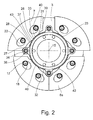
- FIG. 1 For example, an absorber system 1 with an absorber mass carrier 3a is shown which, as in FIG Fig. 3 illustrated, having two axially spaced absorber mass carrier elements 5a and 5b.
- Fig. 1 and 2 is the operating principle of the absorber system 1 by means of absorber mass units 8a, each with at least one absorber mass 7a, these absorber mass units 8a themselves, like Fig. 3 further shows axially located between the two absorber mass carrier elements 5a and 5b.
- the same operating principle also applies to a second absorber mass carrier 3b having second absorber mass units 8b with at least one absorber mass 7b, which in FIG Fig.
- absorber masses 7a is in the Fig. 1 and 2 in each case the absorber mass carrier element 5a arranged in the viewing direction axially in front of the absorber masses 7a is removed, and only the absorber mass carrier element 5b arranged axially behind the absorber masses 7a in the viewing direction is shown. As already mentioned, the absorber mass carrier element 5b is connected by spacers 11a to the absorber mass carrier element 5a.
- absorber masses 7a have each trained in pairs guideways 22 for receiving rolling bodies 20, wherein the guide tracks 22 are designed such that they allow a radial relative movement of the absorber masses 7a relative to the rolling bodies 20.
- the absorber masses 7a have, radially inward on their peripheral sides 42 adjacent stop sides 43.
- guideways 13 are provided, which have a curved course. As shown in Fig. 1 or 2 the guideways 13 each have an exit area 14, in which the respective guide track 13 has the greatest radial distance from a central axis 15, and via connection regions 17 which, extending circumferentially opposite one another, adjoin both sides of the output region 14.
- the guideways 22 provided on the absorber masses 7a, 7b also have a curved course, each having an exit region 24, in which the respective guideway 22 has the smallest radial distance from the central axis 15, and with connection regions 25 which extend circumferentially opposite each other , connect to both sides of the output area 24.
- the guideways 22 are each provided on both sides of a Tilgermassen scholars 35 of the respective absorber mass.
- This absorber mass center 35 is located in a middle extent radius 36a of the absorber masses 7a, which is arranged in driving operation at a distance R1 relative to the central axis 15.
- the state of the absorber masses 7a when driving is in Fig. 1 shown, and is when the absorber system 1 is operated at a speed at which the centrifugal force exceeds the weight.
- the absorber masses 7a strive radially outwards, so that the rolling bodies 20 each position themselves in the output region 24 of the respective guide track 22, that is to say in that region which has the smallest radial distance from the central axis 15.
- the rolling bodies 20 are supported in each case in the exit region 14 of the absorber mass carrier elements 5a and 5b, ie in that region which has the greatest radial distance from the central axis 15.
- the absorber masses 7a each have at their radially inner ends in each case a geometric Anformung 28 which has a first contact portion 26 in the peripheral middle part, in the peripheral side outer parts on the other hand via second contact areas 27.
- the first contact area 26 has an area center 37, which divides the first contact region 29 into molding halves 23.
- This geometric Anformung 28 acts in the manner to be described below with radially inward the absorber masses 7 a provided stops 31 which are taken together on an annular member 32.
- the annular member 32 has in the circumferential direction between two absorber masses 7a via a respective holder 34 which encloses a respective spacer 11 a, so that the holder 34 each serves as a Anschlagaufivity 38.
- the annular member 32 is thus rotatably on the absorber mass carrier element 5b and thus received on Tilgermassenlasi 3.
- a circumferentially extending annular body 33 acts between each two Anschlagaufivity 38 each with a stop profile 40.
- Anschlagaufillon 38 and stop profiles 40 together form stops 31 on the annular member 32nd
- the absorber masses 7a strive radially outwards under the effect of the centrifugal force so that the rolling elements 20 can respectively position themselves in the exit region 24 of the respective guideway 22 of the absorber masses 7a , Although torsional vibrations can enforce deflections of the absorber masses 7a in the circumferential direction, whereby the rolling elements 20 are deflected out of the output regions 14, 24 of the guideways 13, 22 in their connection regions 17, 25, however, with a decaying torsional vibration always a provision of the rolling elements 20 in the starting position below the effect of centrifugal force.
- the two absorber masses 7a located radially below the central axis 15 likewise fall radially inwards until their stop sides 43 with the first contact areas 26 formed thereon, which are relevant for the movement direction, abut on the associated stop profile 40 of the stop 31 on the annular body 33 of the annular component 32 have come, and until also the relevant for the direction of movement second contact portions 27 of the respective absorber masses 7a at the corresponding brackets 34 and thus at the Anschlagaufillon 38 of the annular member 32 come into abutment. In this way it is prevented that the two radially located below the central axis 15 absorber masses 7a reach with their peripheral sides 42 in abutment against each other.
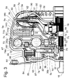
- Fig. 3 shows in detail, is for the absorber masses 7a provided on the first absorber mass carrier 3a, this axially between two absorber mass carrier elements 5a and 5b record, and for the absorber masses 7b on the second absorber mass carrier 3b, this axially between two absorber mass carrier elements 5c and 5d record. Furthermore, it is off Fig. 3 can be seen that the absorber masses 7a of the first absorber mass carrier 3a when driving have a mean radius of extent 36a, the absorber masses 7b of the second absorber mass carrier 3a, however, when driving over a mean extension radius 36b.
- the distance R1 of the mean extension radius 36a of the absorber masses 7a with respect to the central axis 15 is significantly greater than the distance R2 of the mean extension radius 36b of the absorber masses 7b with respect to the central axis 15.
- the absorber masses 7a thus provide - mass uniformity with the absorber masses 7b assuming a significantly higher Mass moment of inertia as the absorber masses 7a.
- the absorber mass carrier 3b is designed to be very compact radially, so that together with the absorber mass unit 8b it is able to make advantageous use of the free space in the axial extension region of a coupling device 64 of a coupling arrangement 56, but arranged radially inside it.
- the annular member 32 is provided whose function in connection with the Fig. 2 and 3 has already been dealt with in detail.
- the absorber mass units 8a, 8b provided on the two absorber mass carriers 3a, 3b are preferably suitable for repelling propulsion of an engine such as an internal combustion engine with different orders, however, the lower mass inertia second absorber mass unit 8b may also serve to to assist the first absorber mass unit 8a in the cancellation of excitations of a certain order, so that the second absorber mass unit 8b is at least substantially tuned to excitations of the same order as the first absorber mass unit 8a.
- the guide tracks 13 are at least substantially identical in the absorber masses 7a and 7b of the absorber mass units 8a and 8b. If, on the other hand, suggestions of different orders are to be redeemed, then the guideways differ from one another, provided that the same rolling elements 20 are to be used for both guideways for cost reasons.
- the first absorber mass unit 8a may be provided for the cancellation of orders of the second order, while the second absorber mass unit 8b may be for the cancellation of first order suggestions. This is advantageous when the engine preceding the absorber system 1 is designed as a 4-cylinder engine in which a cylinder deactivation leads to an operation with only two cylinders.
- the coupling arrangement 56 serving to receive the two absorber mass carriers 3a and 3b with their absorber mass units 8a and 8b has a housing 54 and has, as a hydrodynamic torque converter 90, a hydrodynamic circuit 60 with impeller 61, turbine wheel 62 and stator 63.
- the already mentioned coupling device 64 is connected to a clutch piston 65 and a friction disk clutch 66 is formed, wherein radially outer friction disk elements 84 of the friction disk clutch 66 are in meshing engagement with an outer wall 86 of the housing 54 and radially inner Reibusionn institute 85 of Reibusionnkupplung 66 in meshing engagement with a friction plate element support 87 which engages a damping input 67 of a damping device 70.
- the clutch device 64 can be moved between an engagement position and a disengagement position.
- the damping input 67 is connected via a first damping unit 68 to a damping intermediate part 74 which has two components 74a and 74b arranged at an axial distance from one another and held at a fixed axial distance by means of spacer elements 81.
- Via a second damping unit 69 the damping intermediate part 74 is connected to a damping output 72 which cooperates with a hub 71 acting as an output 73.
- the damping device 70 together with the absorber system 1 serves as a torsional vibration damper 30.
- the absorber mass carrier element 5a of the first absorber mass carrier 3a has a radial extension 78 engaging radially inward in order to make a connection 77 with the intermediate damping part 74 by means of the spacing elements 81.
- the second absorber mass carrier 3b is also connected to the damping intermediate part 74 by means of an axial compression 79 provided on the absorber mass carrier element 5d and extending in the direction of the damping device 70.
- the latter connection 80 is produced by means of welding.
- the two absorber mass carriers 3a and 3b of the absorber system 1 thus act on the respectively same components of the damping device 70, namely on the damping intermediate part 74, but it is avoided to arrange a absorber mass carrier in the direction of the torque transmission path in front of the drive-side damping unit 68.
- the reason for this is due to the fact that considerable torsional vibrations may be present in front of the drive-side damping unit 68 due to the lack of damping.
- the absorber mass carriers 3a and 3b are assigned to the damping intermediate part, 74, the drive-side damping unit 68 vibration-reducing.
- the respective associated absorber masses 7a, 7b may be designed to be low in mass for both absorber mass carriers 3a, 3b, and yet are deflected only to a slight extent when torsional vibrations occur in the circumferential direction.
- the absorber masses 7a, 7b the following must be added:
- the absorber masses 7a have a plurality of absorber mass elements 44a to 44c in the axial direction, while the absorber masses 7b are integrally formed in the axial direction.
- the absorber mass elements 44a to 44c are sheet metal elements in which the guideways 13a can be hardened at low cost over the entire web depth. Subsequently, the absorber mass elements 44a to 44c either, after riveting together, placed on the rolling elements 20, or the absorber mass elements 44a to 44c are placed without riveting on the rolling body 20.
- the absorber masses 7b which are integral in the axial direction are preferably made of solid steel, and are milled, for example, to obtain the shape intended for this purpose.
- the tolerances on the guideways of the corresponding absorber mass carrier elements can be limited and thereby the efficiency of the respective absorber mass unit 8b can be increased.
- the absorber masses 7a of the first absorber mass unit 8a may be integrally formed in the axial direction and the absorber masses 7b of the second absorber mass unit 8b may be formed axially with a plurality of absorber mass elements 44a to 44c.
- Other combinations are also possible, such as the formation of both damper masses 7a, 7b in the same way, so either both each with a plurality of Tilgermassenmaschinen, or both in one piece in the axial direction.
- damping units 68 and 69 are designed for full load so as to avoid running to an end stop within the torque range provided by a drive, such as an internal combustion engine, or when one of the damper units 68, 69 is at partial load to be, for that ensuring that only the output-side damping unit 69 experiences such a design, in which it is permitted that this damping unit 69 reaches an end stop within the torque range supplied by the drive.
- damping unit 69 it may be useful to design the output-side damping unit 69 to partial load, for example, if a damping unit of low rigidity is needed to suppress certain torsional vibrations. If this is not the case, both damping units 68, 69 are designed for full load, so that both damping units 68 and 69 are available within the torque range achievable by the respective drive.
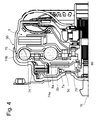
- the second absorber mass carrier 3b of the absorber system 1 is connected to the damping intermediate portion 74 of the damper 70 of the torsional vibration damper 30, but the absorber mass carrier 3b has only a single absorber mass carrier element 5c which is used to make the connection 80 with the intermediate damping member 74 with a direction towards the damper 70 expansive Axialausd Wegung 79 is provided.
- absorber masses 7b are arranged, which serve to form the second absorber mass unit 8b. Due to the saving of a absorber mass carrier element in relation to the in Fig. 3 shown construction space is created, which can be filled by additional absorber masses 7b of the second absorber mass unit 8b.
- the performance of the second absorber mass unit 8b compared to the in Fig. 3 shown embodiment without installation space disadvantages can be increased.
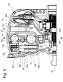
- connection 80 of the second absorber mass carrier 3b of the absorber system 1 is made radially larger than the central axis 15 by engaging the absorber mass carrier element 5d of the absorber mass carrier 3b on the spacers 81 of the intermediate damping element 74 of the damping device 70 of the torsional vibration damper 30.
- the two components 74a, 74b of the damping intermediate part 74 are held by the spacing elements 81 at a predetermined distance from one another.
- the absorber masses 7b of the second absorber mass unit 8b can also be radially enlarged, so that a comparison with the embodiment Fig. 3 significantly higher mass moment of inertia can be generated by the second absorber mass unit 8b.
- the mean extension radius 36b of the absorption mass unit 8b deviates from the comparable extension radius of the Figure 3 from, and thus the distance R2 'of this extension radius 36b relative to the central axis 15th
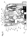
- Fig. 5 also has Fig. 6 the outer wall 86 of the housing 54 of the coupling arrangement 56 in the axial extension region region of the friction disc clutch 66 of the coupling device 64 undergo a radial widening in order to create additional installation space. Notwithstanding the execution according to Fig. 5 is included Fig. 6 Radially sealed within the outer wall 86 of the housing 54, the second absorber mass carrier 3b provided with the absorber mass unit 8b, so that this absorber mass carrier 3b, the coupling means 64 radially encloses.
- the radially further inwardly disposed coupling device 64 requires a radially outer friction plate element carrier 88, which is fastened to a cover 89 of the coupling arrangement 56 in the absence of a toothed engagement with the outer wall 86 of the housing 54.
- the radially outer friction plate element carrier 88 carries radially outwardly the annular member 32, which in terms of its functional determination in the Fig. 1 and 2 already shown and described for this purpose.
- the radially outer friction plate element carrier 88 is in operative connection via the friction disk elements 84, 85 with the radially inner friction disk element carrier 87, and therefore also with the damping input 67 of the damping device 70.
- the second absorber mass carrier 3a is formed with two absorber mass carrier elements 5c and 5d, wherein the absorber mass carrier element 5d is integrally formed with the component 74a of the intermediate damping part 74 of the damping device 70.
- the second absorber mass carrier 3b By arranging the second absorber mass carrier 3b closely within the outer wall 86 of the housing 54, the second absorber mass unit 8b is moved radially outward as far as possible with a radially large distance R2 'from the central axis 15.
- the absorber masses 7b of the second absorber mass unit 8b can also be used be enlarged radially, so that a respect to the embodiment according to Fig. 3 a much higher mass moment of inertia can be generated by the second absorber mass unit 8b.
- the mean extension radius 36b of the absorption mass unit 8b deviates from the comparable extension radius of the Figure 3 from, and thus also the distance R2 "of this extension radius 36b with respect to the central axis 15.
Landscapes
- Engineering & Computer Science (AREA)
- General Engineering & Computer Science (AREA)
- Physics & Mathematics (AREA)
- Acoustics & Sound (AREA)
- Aviation & Aerospace Engineering (AREA)
- Mechanical Engineering (AREA)
- Mechanical Operated Clutches (AREA)
Abstract
Ein Torsionsschwingungsdämpfer (30) ist mit einem Tilgersystem (1) und mit einer Dämpfungseinrichtung (70) ausgebildet, wobei das Tilgersystem (1) einen ersten Tilgermassenträger (3a) zur Aufnahme wenigstens einer ersten Tilgermasseneinheit (8a) und einen zweiten Tilgermassenträger (3b) zur Aufnahme wenigstens einer zweiten Tilgermasseneinheit (8b) aufweist, und die Dämpfungseinrichtung (70) zumindest über einen Dämpfungseingang (67) verfügt, der mit einer antriebsseitigen Dämpfungseinheit (68) in Wirkverbindung steht, zwischen der und einer abtriebsseitigen Dämpfungseinheit (69) ein Dämpfungszwischenteil (74) wirksam ist, und die abtriebsseitige Dämpfungseinheit (69) mit einem Dämpfungsausgang (72) ausgebildet ist, der mit einem Abtrieb (73) verbunden ist. Der Tilgermassenträger (3a) ist mit der wenigstens einen ihm zugeordneten Tilgermasseneinheit (8a) ebenso wie der Tilgermassenträger (3b) mit der wenigstens einen ihm zugeordneten Tilgermasseneinheit (8b) wirkungsmäßig dem Dämpfungszwischenteil (74) zugeordnet.A torsional vibration damper (30) is formed with a damping system (1) and with a damping device (70), wherein the absorber system (1) comprises a first absorber mass carrier (3a) for receiving at least one first absorber mass unit (8a) and a second absorber mass carrier (3b) Receiving at least one second absorber mass unit (8b), and the damping device (70) has at least one damping input (67), which is in operative connection with a drive-side damping unit (68), between the and a driven-side damping unit (69) an intermediate damping part (74 ), and the output side damping unit (69) is formed with a damping output (72) connected to an output (73). The absorber mass carrier (3a) is associated with the at least one absorber mass unit (8a) assigned to it as well as the absorber mass carrier (3b) with the at least one absorber mass unit (8b) assigned to it to the intermediate damping element (74).
Description
Die vorliegende Erfindung betrifft einen Torsionsschwingungsdämpfer mit einem Tilgersystem und mit einer Dämpfungseinrichtung, wobei das Tilgersystem einen ersten Tilgermassenträger zur Aufnahme wenigstens einer ersten Tilgermasseneinheit und einen zweiten Tilgermassenträger zur Aufnahme wenigstens einer zweiter Tilgermasseneinheit aufweist, und die Dämpfungseinrichtung zumindest über einen Dämpfungseingang verfügt, der mit einer antriebsseitigen Dämpfungseinheit in Wirkverbindung steht, zwischen der und einer abtriebsseitigen Dämpfungseinheit ein Dämpfungszwischenteil wirksam ist, und die abtriebsseitige Dämpfungseinheit mit einem Dämpfungsausgang ausgebildet ist, der mit einem Abtrieb verbunden ist.The present invention relates to a torsional vibration damper with a damping system and with a damping device, wherein the absorber system has a first absorber mass carrier for receiving at least a first absorber mass unit and a second absorber mass carrier for receiving at least a second absorber mass unit, and the damping device has at least one damping input, with a Drive-side damping unit is operatively connected, between the and a driven-side damping unit, a damping intermediate part is effective, and the output-side damping unit is formed with a damping output, which is connected to an output.
Ein derartiger Torsionsschwingungsdämpfer ist aus der
In
Zurückkommend auf
Die Tilgermassen sind jeweils beidseits eines gemeinsamen Tilgermassenträgers aufgenommen. Nachteilig bei einer derartigen Lösung ist, dass Verbindungselemente, welche die Tilgermassen mit den Tilgermassenträgern verbinden, jeweils eine hohe Hertz'sche Pressung erfahren. Diese Pressung kann sich nochmals steigern, wenn es bei geringem Querschnitt des jeweiligen Tilgermassenträgers aufgrund sehr kurzer Führungslänge zu einem Verkippen der Verbindungselemente kommt, wodurch zusätzlich Kantenpressungen entstehen.The absorber masses are each taken on both sides of a common Tilgermassenträgers. A disadvantage of such a solution is that connecting elements, which connect the absorber masses with the absorber mass carriers, each experience a high Hertzian pressure. This pressure can increase even further if, with a small cross section of the respective absorber mass carrier, the connecting elements are tilted due to the very short guide length, which additionally produces edge pressures.
Durch die
Aufgrund der Anordnung der Tilgermassen am Dämpfungseingang der Dämpfungseinrichtung sind diese den auf der Antriebsseite der Dämpfungseinrichtung vorherrschenden, ungedämpften Torsionsschwingungen ausgesetzt. Dadurch müssen die Tilgermassen zum einen eine erheblich höhere Masse aufweisen, als dies auf der Abtriebsseite der Dämpfungseinrichtung der Fall wäre, und zum anderen besteht auch für das Tilgersystem das Risiko einer Schädigung oder Zerstörung, wenn es aufgrund starker Torsionsschwingungen des öfteren zu einer Auslenkung der Tilgermassen relativ zum jeweiligen Tilgermassenträger über die vorgegebene Auslenkweite hinaus kommen sollte.Due to the arrangement of the absorber masses at the damping input of the damping device, these are exposed to the prevailing on the drive side of the damping device, undamped torsional vibrations. As a result, the absorber masses must on the one hand have a significantly higher mass than would be the case on the output side of the damping device, and on the other hand, there is also for the absorber system the risk of damage or destruction if, due to strong torsional oscillations, it is often the case that deflection of the absorber masses relative to the respective absorber mass carrier should exceed the predetermined deflection distance.
Der Erfindung liegt die Aufgabe zugrunde, einen Torsionsschwingungsdämpfer mit einem Tilgersystem und mit einer Dämpfungseinrichtung derart auszubilden, dass die darin vorgesehenen Tilgermassen trotz massearmer Ausbildung Anregungen eines Antriebs, wie beispielsweise einer Brennkraftmaschine, mit unterschiedlichen Ordnungen wirksam tilgen.The invention has the object of providing a Torsionsschwingungsdämpfer with a Tilgersystem and with a damping device in such a way that the absorber masses provided therein, despite low training training suggestions of a drive, such as an internal combustion engine, with different orders effectively.
Gemäß der vorliegenden Erfindung wird diese Aufgabe gelöst durch einen Torsionsschwingungsdämpfer mit einem Tilgersystem und mit einer Dämpfungseinrichtung, wobei das Tilgersystem einen ersten Tilgermassenträger zur Aufnahme wenigstens einer ersten Tilgermasseneinheit mit zumindest einer Tilgermasse und einen zweiten Tilgermassenträger zur Aufnahme wenigstens einer zweiten Tilgermasseneinheit mit zumindest einer Tilgermasse aufweist, und die Dämpfungseinrichtung zumindest über einen Dämpfungseingang verfügt, der mit einer antriebsseitigen Dämpfungseinheit in Wirkverbindung steht, zwischen der und einer abtriebsseitigen Dämpfungseinheit ein Dämpfungszwischenteil wirksam ist, und die abtriebsseitige Dämpfungseinheit mit einem Dämpfungsausgang ausgebildet ist, der mit einem Abtrieb verbunden ist.According to the present invention, this object is achieved by a torsional vibration damper with a damping system and with a damping device, the absorber system having a first absorber mass carrier for receiving at least a first absorber mass unit with at least one absorber mass and a second absorber mass carrier for receiving at least one second absorber mass unit with at least one absorber mass and the damping device has at least one damping input, which is operatively connected to a drive-side damping unit, between which and a driven-side damping unit, an intermediate damping part is effective, and the output-side damping unit is formed with a damping output, which is connected to an output.
Hierbei ist der erste Tilgermassenträger mit der wenigstens einen ersten Tilgermasseneinheit ebenso wie der zweite Tilgermassenträger mit der wenigstens einen zweiten Tilgermasseneinheit wirkungsmäßig dem Dämpfungszwischenteil zugeordnet.In this case, the first absorber mass carrier with the at least one first absorber mass unit as well as the second absorber mass carrier with the at least one second absorber mass unit are operatively associated with the intermediate damping component.
Da sich der Dämpfungszwischenteil bei einer Dämpfungseinrichtung, die, wie im vorliegenden Fall, aufgrund zweier Dämpfungseinheiten, nämlich einer antriebsseitigen Dämpfungseinheit und einer abtriebsseitigen Dämpfungseinheit, mehrstufig ist, abtriebsseitig des Dämpfungseingangs befindet, und damit in Antriebsrichtung hinter demjenigen Bereich einer Dämpfungseinrichtung liegt, in welchem aufgrund fehlender Dämpfung erhebliche Torsionsschwingungen anliegen, können die Tilgermassen der jeweiligen Tilgermasseneinheit massearm ausgebildet sein, und werden dennoch lediglich in geringem Maß beim Auftreten von Torsionsschwingungen in Umfangsrichtung ausgelenkt. Konsequenterweise ist bei Zuordnung beider Tilgermassenträger mit der jeweils wenigstens einen Tilgermasseneinheit wirkungsmäßig zum Dämpfungszwischenteil dafür zu sorgen, dass entweder alle Dämpfungseinheiten auf Volllast ausgelegt werden, oder aber dann, wenn zumindest eine der Dämpfungseinheiten auf Teillast ausgelegt werden soll, dafür zu sorgen, dass dies lediglich die abtriebsseitige Dämpfungseinheit ist. Die Begründung für eine derartige Auslegung liegt darin, dass auf jeden Fall vermieden werden soll, dass die Tilgermasseneinheiten antriebsseitig wirksam werden. Dies könnte bei Auslegung der antriebsseitigen Dämpfungseinheit auf Teillast allerdings nicht ausgeschlossen werden, da diese Dämpfungseinheit dann, wenn ihr Verformungsweg bei Auslegung auf Teillast verbraucht wäre, eine zumindest im Wesentlichen synchrone Bewegung des Dämpfungszwischenteils mit dem Dämpfungseingang entstehen lassen würde, so dass die Tilgermasseneinheiten, die wirkungsmäßig dem Dämpfungszwischenteil zugeordnet sind, an der Bewegung des Dämpfungseingangs zumindest im Wesentlichen teilnehmen würden. Ein solches Vorkommnis ist ausgeschlossen, wenn stattdessen die abtriebsseitige Dämpfungseinheit auf Teillast ausgelegt ist, und die antriebsseitige Dämpfungseinheit auf Volllast. Dann kann zwar, wenn bei der abtriebsseitigen Dämpfungseinheit der Verformungsweg bei Auslegung auf Teillast verbraucht wäre, eine zumindest im Wesentlichen synchrone Bewegung des Dämpfungszwischenteils mit dem Dämpfungsausgang entstehen, jedoch steht auch dann noch die antriebsseitige Dämpfungseinheit zur Verfügung, um die am Dämpfungseingang anliegenden Torsionsschwingungen zu dämpfen.Since the intermediate damping part in a damping device, which, as in the present case, due to two damping units, namely a drive-side damping unit and a driven side damping unit, is multi-stage, the output side of the damping input, and thus lies in the drive direction behind that area of a damping device, in which due lack of damping applied considerable torsional vibrations, the absorber masses of the respective absorber mass unit can be formed massearm, and yet only to a small extent in the occurrence of torsional vibrations in the circumferential direction deflected. Consequently, when assigning both Tilgermassenträger with the respective at least one Tilgermasseneinheit operatively to ensure damping intermediate part that either all damping units are designed for full load, or if at least one of the damping units should be designed to partial load, to ensure that this only the output side damping unit is. The rationale for such an interpretation is that it should in any case be avoided that the absorber mass units become effective on the drive side. However, this could not be ruled out in the design of the drive-side damping unit to partial load, since this damping unit would, if their deformation would be consumed in design to partial load, would create an at least substantially synchronous movement of the damping intermediate part with the damping input, so that the absorber mass units, the are operatively associated with the damping intermediate part, would participate in the movement of the damping input at least substantially. Such an occurrence is excluded if instead the driven side damping unit is designed for partial load, and the drive side damping unit to full load. Then, if at the output side damping unit of the deformation would be consumed in design to partial load, an at least substantially synchronous movement of the damping intermediate part with the damping output arise, but even then the drive-side damping unit is available to dampen the damping input applied to the torsional vibrations ,
Es kann sinnvoll sein, die abtriebsseitige Dämpfungseinheit auf Teillast auszulegen, beispielsweise wenn zur Unterdrückung bestimmter Torsionsschwingungen eine Dämpfungseinheit geringer Steifigkeit benötigt wird. Sofern dies nicht der Fall ist, werden mit Vorzug beide Dämpfungseinheiten auf Volllast ausgelegt, so dass bis zum Erreichen des durch den jeweiligen Antrieb erreichbaren Drehmomentmaximums beide Dämpfungseinheiten zur Verfügung stehen.It may be useful to design the output side damping unit to partial load, for example, if a damping unit low stiffness is needed to suppress certain torsional vibrations. If this is not the case, both damping units are preferably designed for full load, so that both damping units are available until reaching the torque maximum achievable by the respective drive.
Mit Vorzug verfügen die Tilgermassen der zumindest zwei Tilgermasseneinheiten, bezogen auf ihren jeweiligen mittleren Erstreckungsradius bei Fahrbetrieb, über unterschiedliche Abstände gegenüber einer Zentralachse, wobei sich der Fahrbetrieb dadurch auszeichnet, dass die auf die Tilgermassen einwirkende Fliehkraft die entgegen wirkende Gewichtskraft übersteigt.With preference, the absorber masses of the at least two absorber mass units, based on their respective average extension radius when driving, have different distances from a central axis, whereby the driving operation characterized in that the force acting on the absorber mass centrifugal force exceeds the counteracting weight.
Durch Anordnung der Tilgermassen zumindest zweier Tilgermasseneinheiten bei Fahrbetrieb derart, dass die Tilgermassen, bezogen auf ihren jeweiligen mittleren Erstreckungsradius, über unterschiedliche Abstände gegenüber einer Zentralachse verfügen, wird die Auslegung unterschiedlicher Tilgermasseneinheiten auf die Tilgung von Anregungen eines Antriebs, wie einer Brennkraftmaschine, mit unterschiedlichen Ordnungen begünstigt, da hierdurch - zusätzlich zur Auslegung der Masse der einzelnen Tilgermassen der jeweiligen Tilgermasseneinheit - ein zweites Auslegungskriterium für die Tilgerwirkung zur Verfügung steht, nämlich der Abstand der Tilgermassen von der Zentralachse. Es wird hierbei die Situation genutzt, dass die Tilgermassen mit zunehmendem Abstand von der Zentralachse zur Erlangung eines bestimmten Massenträgheitsmomentes eine abnehmend große Masse benötigen. Alternativ kann aber auch zusätzlich zu einem zunehmenden Abstand der Tilgermassen von der Zentralachse die Masse der Tilgermassen erhöht werden, um damit sehr hohe Massenträgheitsmomente zu erzeugen, die für die Tilgung extremer Torsionsschwingungen benötigt werden. Umgekehrt können allerdings auch bei zunehmender Annäherung der Tilgermassen an die Zentralachse hierdurch entstehende Bauraumvorteile radial außerhalb der Tilgermassen genutzt werden, beispielsweise für die Unterbringung anderer Bauteile, wie beispielsweise einer Kupplungseinrichtung, die ebenso wie der das Tilgersystem sowie die Dämpfungseinrichtung aufweisende Torsionsschwingungsdämpfer Teil einer Kopplungsanordnung ist.By arranging the absorber masses of at least two absorber mass units while driving in such a way that the absorber masses have different distances relative to a central axis relative to their respective average extension radius, the design of different absorber mass units is based on the cancellation of excitations of a drive, such as an internal combustion engine, with different orders favors, since - in addition to the design of the mass of the individual absorber masses of the respective absorber mass unit - a second design criterion for Tilgerwirkung is available, namely the distance of the absorber masses of the central axis. Here, the situation is used that the absorber masses with increasing distance from the central axis to obtain a certain mass moment of inertia require a decreasing mass. Alternatively, however, in addition to an increasing distance of the absorber masses from the central axis, the mass of the absorber masses can be increased in order to produce very high moments of inertia, which are required for the eradication of extreme torsional vibrations. Conversely, however, even with increasing convergence of the absorber masses to the central axis resulting space advantages radially outside the absorber masses can be used, for example, for the placement of other components, such as a coupling device which is part of a coupling arrangement as well as the absorber system and the damping device having torsional vibration.
Dies trifft insbesondere dann zu, wenn die Tilgermasseneinheiten an unterschiedlichen Stellen der Kopplungsanordnung vorgesehen sind. Hierbei bietet es sich insbesondere an, wenigstens einen ersten Tilgermassenträger und damit eine erste Tilgermasseneinheit axial zwischen der Dämpfungseinrichtung und einem hydrodynamischen Kreis der Kopplungsanordnung zu positionieren, und wenigstens einen zweiten Tilgermassenträger und damit eine zweite Tilgermasseneinheit axial zwischen einer Kupplungseinrichtung der Kopplungsanordnung und der Dämpfungseinrichtung.This is especially true when the absorber mass units are provided at different locations of the coupling arrangement. In this case, it is particularly appropriate to position at least one first absorber mass carrier and thus a first absorber mass unit axially between the damping device and a hydrodynamic circuit of the coupling arrangement, and at least one second absorber mass carrier and thus a second absorber mass unit axially between a coupling device of the coupling arrangement and the damping device.
Mit Vorzug ist hierbei zumindest ein Tilgermassenträger des Tilgersystems derart ausgebildet, dass je eine Tilgermasseneinheit axial zwischen jeweils zwei mit Axialabstand zueinander angeordneten Tilgermassen-Trägerelementen aufgenommen ist, und somit die Hertz'sche Pressung zwischen als Verbindungselemente wirksamen Rollkörpern und Tilgermassen-Trägerelementen einerseits und zwischen den Rollkörpern und Tilgermassen andererseits innerhalb eines problemfreien Belastungsbereichs verbleibt, und Kantenpressungen an den Verbindungselementen weitgehend ausgeschlossen sind.With preference, at least one Tilgermassenträger the absorber system is designed such that each Tilgermasseneinheit is axially received between each two axially spaced Tilgermassen carrier elements, and thus the Hertzian pressure between effective as connecting elements rolling elements and absorber mass carrier elements on the one hand and between the Rolling bodies and absorber masses, on the other hand, remains within a problem-free load range, and edge pressures on the connecting elements are largely excluded.
Da zumindest zwei Tilgermassenträger mit Tilgermasseneinheiten vorhanden sind, können die Tilgermassen der Tilgermasseneinheiten zur Tilgung von Anregungen eines Antriebs, wie einer Brennkraftmaschine, mit zumindest im Wesentlichen gleichen Ordnungen oder aber zur Tilgung von Anregungen unterschiedlicher Ordnungen vorgesehen sein. Sind diese Tilgermasseneinheiten zur Tilgung von Anregungen mit im Wesentlichen gleichen Ordnungen vorgesehen, dann sind die in den Tilgermassenträgern vorgesehenen Führungsbahnen zumindest im Wesentlichen gleich ausgebildet. Sollen dagegen die Tilgermasseneinheiten zur Tilgung von Anregungen mit unterschiedlichen Ordnungen vorgesehen sein, dann sind die in den Tilgermassenträgern vorgesehenen Führungsbahnen unterschiedlich ausgebildet, sofern für die unterschiedlichen Führungsbahnen aus Kostengründen jeweils gleiche Rollkörper Verwendung finden. Zur Tilgung von Anregungen unterschiedlicher Ordnungen ist beispielsweise eine der beteiligten Tilgermasseneinheiten für Anregungen der 2. Ordnung vorgesehen, eine andere der beteiligten Tilgermasseneinheiten dagegen für Anregungen der 1. Ordnung. Dies ist dann vorteilhaft, wenn die dem Tilgersystem vorgeschaltete Brennkraftmaschine als 4-Zylinder-Maschine ausgebildet ist, bei welcher eine Zylinderabschaltung zu einem Betrieb mit lediglich noch 2 Zylindern führt. Im 4-Zylinderbetrieb ist die Tilgung von Anregungen der 2. Ordnung vorzunehmen, im 2-Zylinderbetrieb dagegen die Tilgung von Anregungen der 1. Ordnung. Vergleichbar verhält es sich bei Zylinderabschaltungen von 6-Zylindermaschinen auf 3 Zylinder oder bei Zylinderabschaltungen von 8-Zylindermaschinen auf 4 Zylinder. Im erstgenannten Fall werden alternativ zu Anregungen der 3. Ordnung die Anregungen der 1,5. Ordnung getilgt, und im letztgenannten Fall alternativ zu Anregungen der 4. Ordnung die Anregungen der 2. Ordnung.Since at least two Tilgermassenträger are present with Tilgermasseneinheiten, the absorber masses of absorber mass units for eradicating suggestions of a drive, such as an internal combustion engine, be provided with at least substantially equal orders or for the eradication of suggestions of different orders. If these absorber mass units are provided for the purpose of eradicating suggestions with essentially the same orders, then the guideways provided in the absorber mass carriers are at least substantially the same. If, on the other hand, the absorber mass units are to be provided for the purpose of eradicating suggestions with different orders, then the guideways provided in the absorber mass carriers are designed differently, provided that the same guideways are used for the different guideways for cost reasons. To eradicate suggestions of different orders, for example, one of the absorber mass units involved is provided for excitations of the second order, while another of the involved absorber mass units is intended for excitations of the first order. This is advantageous when the engine upstream of the absorber system is designed as a 4-cylinder engine, in which a cylinder deactivation leads to an operation with only two cylinders. In 4-cylinder operation, the eradication of excitations of the 2nd order is to be carried out, in 2-cylinder operation, however, the eradication of excitations of the 1st order. The same applies to cylinder deactivation of 6-cylinder engines to 3 cylinders or cylinder deactivation of 8-cylinder engines to 4 cylinders. In the former case, as an alternative to suggestions of the third order, the suggestions of 1.5. Order canceled, and in the latter case, as an alternative to suggestions of the 4th order, the suggestions of the 2nd order.
Die Erfindung wird nachfolgend anhand der beiliegenden Figuren detailliert beschrieben. Es zeigt:
-
Fig. 1 eine Draufsicht auf ein Tilgersystem mit Tilgermassen, die in einer Position dargestellt sind, die sie bei Fahrbetrieb mit die Gewichtskraft übersteigender Fliehkraft und frei von eingeleiteten Torsionsschwingungen einnehmen; -
Fig. 2 wieFig. 1 , aber mit den Tilgermassen in einer Position, die bei unter die Gewichtskraft abgesunkener Fliehkraft eingenommen wird; -
Fig. 3 eine Schnittdarstellung durch eine Kopplungsanordnung mit einer Kupplungseinrichtung, einem über Tilgersystem und Dämpfungseinrichtung verfügenden Torsionsschwingungsdämpfer und hydrodynamischem Kreis, mit Anbindung eines ersten Tilgermassenträgers mit einer ersten Tilgermasseneinheit ebenso wie eines zweiten Tilgermassenträgers mit einer zweiten Tilgermasseneinheit an einem Dämpfungszwischenteil der Dämpfungseinrichtung; -
Fig. 4 wieFig. 3 , aber mit konstruktiv anderer Ausgestaltung des zweiten Tilgermassenträgers sowie der zweiten Tilgermasseneinheit; -
Fig. 5 wieFig. 3 , aber mit Anbindung des zweiten Tilgermassenträgers an den Dämpfungszwischenteil der Dämpfungseinrichtung radial weiter entfernt von einer Zentralachse der Kopplungsanordnung; -
Fig. 6 wieFig. 5 , aber mit Anbindung des zweiten Tilgermassenträgers an den Dämpfungszwischenteil der Dämpfungseinrichtung nochmals radial weiter entfernt von der Zentralachse der Kopplungsanordnung.
-
Fig. 1 a plan view of an absorber system with absorber masses, which are shown in a position that they take when driving with the weight of centrifugal force and exempt from incoming torsional vibrations; -
Fig. 2 asFig. 1 but with the absorber masses in a position which is taken with centrifugal force reduced under the weight force; -
Fig. 3 a sectional view through a coupling arrangement with a coupling device, a Tilgersystem damper damper and hydrodynamic circuit, with connection of a first Tilgermassenträgers with a first absorber mass unit as well as a second absorber mass carrier with a second absorber mass unit at a damping intermediate part of the damping device; -
Fig. 4 asFig. 3 but with structurally different design of the second absorber mass carrier and the second absorber mass unit; -
Fig. 5 asFig. 3 but with connection of the second Tilgermassenträgers to the damping intermediate part of the damping device radially further away from a central axis of the coupling arrangement; -
Fig. 6 asFig. 5 but with connection of the second absorber mass carrier to the damping intermediate part of the damping device again radially further away from the central axis of the coupling arrangement.
In
Zur besseren Darstellbarkeit der am Tilgermassenträger 3a aufgenommenen Tilgermassen 7a ist in den
An den Tilgermassen-Trägerelementen 5a und 5b sind, ebenfalls jeweils paarweise, Führungsbahnen 13 vorgesehen, die über einen gekrümmten Verlauf verfügen. Gemäß Darstellung in
Die in den Führungsbahnen 13 und 22 aufgenommenen Rollkörper 20 greifen jeweils beidseits der jeweiligen Führungsbahn 22 in die dort vorgesehenen Führungsbahnen 13 ein. In der Darstellung gemäß
Die Tilgermassen 7a weisen jeweils an ihren radial inneren Enden jeweils eine geometrische Anformung 28 auf, die im umfangsseitig mittleren Teil über einen ersten Kontaktbereich 26 verfügt, in den umfangsseitig äußeren Teilen dagegen über zweite Kontaktbereiche 27. Der erste Kontaktbereich 26 verfügt über eine Bereichsmitte 37, welche den ersten Kontaktbereich 29 in Anformunghälften 23 unterteilt. Diese geometrische Anformung 28 wirkt in nachfolgend noch zu beschreibender Weise mit radial innerhalb der Tilgermassen 7a vorgesehenen Anschlägen 31 zusammen, die an einem ringförmigen Bauteil 32 zusammen gefasst sind.The
Das ringförmige Bauteil 32 verfügt in Umfangsrichtung zwischen je zwei Tilgermassen 7a über je eine Halterung 34, die jeweils ein Abstandsstück 11 a umschließt, so dass die Halterung 34 jeweils als Anschlagaufnehmer 38 dient. Das ringförmige Bauteil 32 ist demnach drehfest an dem Tilgermassen-Trägerelement 5b und damit am Tilgermassenträger 3 aufgenommen. Ein sich in Umfangsrichtung erstreckender Ringkörper 33 wirkt zwischen je zwei Anschlagaufnehmern 38 jeweils mit einem Anschlagprofil 40. Anschlagaufnehmer 38 und Anschlagprofile 40 bilden gemeinsam Anschläge 31 an dem ringförmigen Bauteil 32.The
Wenn das Tilgersystem 1 mit einer Drehzahl betrieben wird, bei welcher die Fliehkraft die Gewichtskraft übersteigt, streben die Tilgermassen 7a unter der Wirkung der Fliehkraft nach radial außen, so dass sich die Rollkörper 20 jeweils im Ausgangsbereich 24 der jeweiligen Führungsbahn 22 der Tilgermassen 7a positionieren können. Torsionsschwingungen können zwar Auslenkungen der Tilgermassen 7a in Umfangsrichtung erzwingen, wodurch die Rollkörper 20 aus den Ausgangsbereichen 14, 24 der Führungsbahnen 13, 22 in deren Anschlussbereiche 17, 25 ausgelenkt werden, jedoch erfolgt bei abklingender Torsionsschwingung stets eine Rückstellung der Rollkörper 20 in die Ausgangsposition unter der Wirkung der Fliehkraft.When the
Fällt die Fliehkraft dagegen unter die Gewichtskraft, beispielsweise bei einem Kriechbetrieb eines Kraftfahrzeuges oder beim Abstellen eines Antriebs, wie beispielsweise einer Brennkraftmaschine, dann fallen die Tilgermassen 7a nach radial innen, um die in
Wie
Aufgrund der zuvor behandelten Unterschiede sind die an den beiden Tilgermassenträgern 3a, 3b vorgesehenen Tilgermasseneinheiten 8a, 8b bevorzugt zur Tilgung von Anregungen eines Antriebs, wie einer Brennkraftmaschine, mit unterschiedlichen Ordnungen geeignet, jedoch kann die mit geringerer Massenträgheit aufwartende zweite Tilgermasseneinheit 8b auch dazu dienen, die erste Tilgermasseneinheit 8a bei der Tilgung von Anregungen einer bestimmten Ordnung zu unterstützen, so dass die zweite Tilgermasseneinheit 8b zumindest im Wesentlichen auf Anregungen der gleichen Ordnung wie die erste Tilgermasseneinheit 8a abgestimmt ist.Because of the differences discussed above, the
Wenn durch beide Tilgermasseneinheiten 8a und 8b zumindest im Wesentlichen Anregungen der gleichen Ordnung zu tilgen ist, sind die Führungsbahnen 13 bei den Tilgermassen 7a und 7b beider Tilgermasseneinheiten 8a und 8b zumindest im Wesentlichen gleich ausgebildet. Sollen dagegen Anregungen unterschiedlicher Ordnungen getilgt werden, dann unterscheiden sich die Führungsbahnen voneinander, sofern für beide Führungsbahnen aus Kostengründen jeweils gleiche Rollkörper 20 Verwendung finden sollen. Beispielsweise kann die erste Tilgermasseneinheit 8a zur Tilgung von Anregungen der 2. Ordnung vorgesehen sein, die zweite Tilgermasseneinheit 8b dagegen zur Tilgung von Anregungen der 1. Ordnung. Dies ist dann vorteilhaft, wenn die dem Tilgersystem 1 vorgeschaltete Brennkraftmaschine als 4-Zylinder-Maschine ausgebildet ist, bei welcher eine Zylinderabschaltung zu einem Betrieb mit lediglich noch 2 Zylindern führt. Im 4-Zylinderbetrieb ist die Tilgung von Anregungen der 2. Ordnung vorzunehmen, im 2-Zylinderbetrieb dagegen die Tilgung von Anregungen der 1. Ordnung. Vergleichbar verhält es sich bei Zylinderabschaltungen von 6-Zylindermaschinen auf 3 Zylinder oder bei Zylinderabschaltungen von 8-Zylindermaschinen auf 4 Zylinder. Im erstgenannten Fall werden alternativ zu Anregungen der 3. Ordnung die Anregungen der 1,5. Ordnung getilgt, und im letztgenannten Fall alternativ zu Anregungen der 4. Ordnung die Anregungen der 2. Ordnung.If at least substantially suggestions of the same order are to be paid off by the two
Die zur Aufnahme der beiden Tilgermassenträger 3a und 3b mit deren Tilgermasseneinheiten 8a und 8b dienende Kopplungsanordnung 56 verfügt über ein Gehäuse 54 und weist, da als hydrodynamischer Drehmomentwandler 90 ausgebildet, einen hydrodynamischen Kreis 60 mit Pumpenrad 61, Turbinenrad 62 und Leitrad 63 auf. Die bereits genannte Kupplungseinrichtung 64 ist mit einem Kupplungskolben 65 sowie mit einer Reibscheibenkupplung 66 ausgebildet, wobei radial äußere Reibscheibenelemente 84 der Reibscheibenkupplung 66 in Verzahnungseingriff mit einer Außenwandung 86 des Gehäuses 54 und radial innere Reibscheibenelemente 85 der Reibscheibenkupplung 66 in Verzahnungseingriff mit einem Reibscheiben-Elemententräger 87 stehen, der an einem Dämpfungseingang 67 einer Dämpfungseinrichtung 70 angreift.. In Abhängigkeit von der Ansteuerung des auf einem Kolbenträger 82 axial verlagerbar angeordneten Kupplungskolbens 65 ist die Kupplungseinrichtung 64 zwischen einer Einrückposition und einer Ausrückposition bewegbar. Der Dämpfungseingang 67 ist über eine erste Dämpfungseinheit 68 mit einem Dämpfungszwischenteil 74 verbunden, das zwei mit Axialabstand zueinander angeordnete und mittels Abstandselementen 81 auf fester axialer Distanz gehaltene Bauteile 74a und 74b aufweist. Über eine zweite Dämpfungseinheit 69 ist das Dämpfungszwischenteil 74 mit einem Dämpfungsausgang 72 verbunden, der mit einer als Abtrieb 73 wirksamen Nabe 71 zusammen wirkt. Die Dämpfungseinrichtung 70 dient gemeinsam mit dem Tilgersystem 1 als Torsionsschwingungsdämpfer 30.The
Wie
Die beiden Tilgermassenträger 3a und 3b des Tilgersystems 1 greifen damit am jeweils gleichen Bauteilen der Dämpfungseinrichtung 70, nämlich am Dämpfungszwischenteil 74, an, jedoch wird vermieden, einen Tilgermassenträger in Richtung des Momentenübertragungsweges vor der antriebsseitigen Dämpfungseinheit 68 anzuordnen. Der Grund hierfür liegt darin begründet, dass vor der antriebsseitigen Dämpfungseinheit 68 aufgrund fehlender Dämpfung erhebliche Torsionsschwingungen anliegen können. Dagegen wirkt bei Zuordnung der Tilgermassenträger 3a und 3b zum Dämpfungszwischenteil 74 die antriebsseitige Dämpfungseinheit 68 schwingungsreduzierend. Folgerichtig können daher für beide Tilgermassenträger 3a, 3b die jeweils zugeordneten Tilgermassen 7a, 7b massearm ausgebildet sein, und werden dennoch lediglich in geringem Maß beim Auftreten von Torsionsschwingungen in Umfangsrichtung ausgelenkt. Zur Ausführung der Tilgermassen 7a, 7b ist folgendes zu ergänzen:The two
Wie bereits erwähnt, weisen die Tilgermassen 7a in Achsrichtung eine Mehrzahl von Tilgermassenelementen 44a bis 44c auf, während die Tilgermassen 7b in Achsrichtung einstückig ausgebildet sind. Bei den Tilgermassenelementen 44a bis 44c handelt es sich um Blechelemente, bei denen die Führungsbahnen 13a bei geringen Kosten jeweils über die gesamte Bahntiefe gehärtet werden können. Anschließend werden die Tilgermassenelemente 44a bis 44c entweder, nach Vernietung miteinander, auf die Rollkörper 20 gesetzt, oder aber die Tilgermassenelemente 44a bis 44c werden vernietungsfrei auf die Rollkörper 20gesetzt. Die in Achsrichtung einstückigen Tilgermassen 7b bestehen dagegen mit Vorzug aus massivem Stahl, und werden beispielsweise zum Erhalt der hierfür bestimmten Form gefräst. Dadurch können die Toleranzen an den Führungsbahnen der entsprechenden Tilgermassen-Trägerelemente eingegrenzt und dadurch die Leistungsfähigkeit der jeweiligen Tilgermasseneinheit 8b erhöht werden. Ebenso können aber auch die Tilgermassen 7a der ersten Tilgermasseneinheit 8a in Achsrichtung einstückig und die Tilgermassen 7b der zweiten Tilgermasseneinheit 8b axial mit einer Mehrzahl von Tilgermassenelementen 44a bis 44c ausgebildet sein. Weitere Kombinationen sind ebenfalls möglich, wie die Ausbildung beider Tilgermassen 7a, 7b auf gleiche Weise, also entweder beide jeweils mit einer Mehrzahl von Tilgermassenelementen, oder beide jeweils in Achsrichtung einstückig.As already mentioned, the
Trotz dieser vorteilhaften Ausgestaltung sind Vorkehrungen zu treffen, um zu vermeiden, dass den Tilgermassen 7a, 7b eine dem Dämpfungseingang 67 der Dämpfungseinrichtung 70 entsprechende Bewegung aufgezwungen wird. Diese Vorkehrungen werden durch entsprechende Auslegung der Dämpfungseinheiten 68 und 69 getroffen. Entweder werden beide Dämpfungseinheiten 68 und 69 auf Volllast ausgelegt, so dass vermieden wird, dass diese innerhalb des von einem Antrieb, wie einer Brennkraftmaschine, gelieferten Drehmomentbereichs an einen Endanschlag laufen, oder aber es wird, wenn eine der Dämpfungseinheiten 68, 69 auf Teillast ausgelegt werden soll, dafür gesorgt, dass ausschließlich die abtriebsseitige Dämpfungseinheit 69 eine derartige Auslegung erfährt, bei welcher zugelassen wird, dass diese Dämpfungseinheit 69 innerhalb des vom Antrieb gelieferten Drehmomentbereichs einen Endanschlag erreicht. Mit Erreichen des Endanschlages wird zwar der Abtrieb 73 eine bewegungsgleiche Mitnahme durch den Dämpfungszwischenteil 74 erfahren, jedoch liegt selbst dann noch eine Dämpfung für die Tilgermassen 7a, 7b beider Tilgermassenträger 3a, 3b vor, und zwar aufgrund der auf Volllast ausgelegten antriebsseitigen Dämpfungseinheit 68.Despite this advantageous embodiment, provision must be made to avoid that the
Trotz dieser Situation kann es sinnvoll sein, die abtriebsseitige Dämpfungseinheit 69 auf Teillast auszulegen, beispielsweise wenn zur Unterdrückung bestimmter Torsionsschwingungen eine Dämpfungseinheit geringer Steifigkeit benötigt wird. Sofern dies nicht der Fall ist, werden beide Dämpfungseinheiten 68, 69 auf Volllast ausgelegt, so dass innerhalb des durch den jeweiligen Antrieb erreichbaren Drehmomentbereiches beide Dämpfungseinheiten 68 und 69 zur Verfügung stehen.Despite this situation, it may be useful to design the output-
Nachfolgend sind weitere Ausführungen des Torsionsschwingungsdämpfers 30 behandelt, so dass lediglich diejenigen Merkmale beschrieben sind, welche eine Abweichung gegenüber der in
Auch bei der Ausführung gemäß
Bei der Ausführung nach
Diese Ausführung des zweiten Tilgermassenträgers 3b mit der zweiten Tilgermasseneinheit 8b ist möglich, da die Außenwandung 86 des Gehäuses 54 der Kopplungsanordnung 56 gegenüber der Ausführung nach
Abweichend von der Ausführung nach
Ebenso wie bei
Wegen der Anordnung der Kupplungseinrichtung 64 radial innerhalb des zweiten Tilgermassenträgers 3b mit der zweiten Tilgermasseneinheit 8b genügt bei dieser Ausführung ein Kolbenträger 82 mit konventioneller Erstreckungsweite, und zudem ein Kupplungskolben 65 konventioneller Ausgestaltung.Because of the arrangement of the
Der zweite Tilgermassenträger 3a ist mit zwei Tilgermassen-Trägerelementen 5c und 5d ausgebildet, wobei das Tilgermassen-Trägerelement 5d mit dem Bauteil 74a des Dämpfungszwischenteils 74 der Dämpfungseinrichtung 70 einstückig ausgebildet ist. Durch Anordnung des zweiten Tilgermassenträgers 3b dicht innerhalb der Außenwandung 86 des Gehäuses 54 ist die zweite Tilgermasseneinheit 8b mit radial großem Abstand R2" gegenüber der Zentralachse 15 so weit als möglich nach radial außen gerückt. Alternativ oder ergänzend können auch die Tilgermassen 7b der zweiten Tilgermasseneinheit 8b radial vergrößert werden, so dass ein gegenüber der Ausführung nach
- 11
- Tilgersystemabsorber system
- 33
- TilgermassenträgerTilgermassenträger
- 55
- Tilgermassen-TrägerelementeAbsorber masses support elements
- 77
- Tilgermassenabsorber masses
- 88th
- Tilgermasseneinheitabsorber mass
- 1111
- Abstandsstückespacers
- 1313
- Führungsbahnenguideways
- 1414
- Ausgangsbereichoutput range
- 1515
- Zentralachsecentral axis
- 1717
- Anschlussbereichelands
- 2020
- Rollkörperroll body
- 2222
- Führungsbahnguideway
- 2424
- Ausgangsbereichoutput range
- 2525
- Anschlussbereichterminal area
- 2626
- Kontaktbereichcontact area
- 2727
- Kontaktbereichcontact area
- 2828
- geometrische Anformunggeometric shape
- 3030
- Torsionsschwingungsdämpfertorsional vibration damper
- 3131
- Anschlagattack
- 3232
- ringförmiges Bauteilannular component
- 3333
- Ringkörperring body
- 3434
- Halterungbracket
- 3535
- TilgermassenzentrumTilgermassenzentrum
- 3636
- mittlerer Erstreckungsradiusaverage radius of extent
- 3737
- Bereichsmittearea center
- 3838
- AnschlagaufnehmerAnschlagaufnehmer
- 4040
- Anschlagprofilstop profile
- 4242
- Umfangsseiteperipheral side
- 4343
- Anschlagseitestop side
- 4444
- Tilgermassenelementeabsorber mass
- 5454
- Gehäusecasing
- 5656
- Kopplungsanordnungcoupling arrangement
- 6060
- hydrodynamischer Kreishydrodynamic circuit
- 6161
- Pumpenradimpeller
- 6262
- Turbinenradturbine
- 6363
- Leitradstator
- 6464
- Kupplungseinrichtungcoupling device
- 6565
- Kupplungskolbenclutch piston
- 6666
- Reibscheibenkupplungfriction disc clutch
- 6767
- Dämpfungseingangdamping input
- 6868
- antriebsseitige erste Dämpfungseinheitdrive-side first damping unit
- 6969
- abtriebsseitige zweite Dämpfungseinheitoutput side second damping unit
- 7070
- Dämpfungseinrichtungattenuator
- 7171
- Nabehub
- 7272
- Dämpfungsausgangdamping output
- 7373
- Abtrieboutput
- 7474
- DämpfungszwischenteilDamping intermediate part
- 7575
- Anbindungconnection
- 7777
- Verbindungconnection
- 7878
- Radialverlängerungradial extension
- 7979
- AxialausdrückungAxialausdrückung
- 8080
- Verbindungconnection
- 8181
- Abstandselementespacers
- 8282
- Kolbenträgerpiston carrier
- 8484
- radial äußere Reibscheibenelementeradially outer friction disk elements
- 8585
- radial innere Reibscheibenelementeradially inner friction disk elements
- 8686
- Außenwandung des GehäusesOuter wall of the housing
- 8787
- radial innerer Reibscheiben-Elemententrägerradially inner friction plate element carrier
- 8888
- radial äußerer Reibscheiben-Elemententrägerradially outer friction plate element carrier
- 8989
- Deckelcover
- 9090
- hydrodynamischer Drehmomentwandlerhydrodynamic torque converter
Claims (9)
Applications Claiming Priority (1)
| Application Number | Priority Date | Filing Date | Title |
|---|---|---|---|
| DE201310219503 DE102013219503A1 (en) | 2013-09-27 | 2013-09-27 | torsional vibration damper |
Publications (2)
| Publication Number | Publication Date |
|---|---|
| EP2853772A1 true EP2853772A1 (en) | 2015-04-01 |
| EP2853772B1 EP2853772B1 (en) | 2018-09-26 |
Family
ID=51359313
Family Applications (1)
| Application Number | Title | Priority Date | Filing Date |
|---|---|---|---|
| EP14181711.4A Active EP2853772B1 (en) | 2013-09-27 | 2014-08-21 | Torsion vibration damper |
Country Status (2)
| Country | Link |
|---|---|
| EP (1) | EP2853772B1 (en) |
| DE (1) | DE102013219503A1 (en) |
Cited By (6)
| Publication number | Priority date | Publication date | Assignee | Title |
|---|---|---|---|---|
| US20150101450A1 (en) * | 2011-11-28 | 2015-04-16 | Schaeffler Technologies Gmbh & Co. Kg | Centrifugal force pendulum |
| WO2015149783A1 (en) * | 2014-04-02 | 2015-10-08 | Schaeffler Technologies AG & Co. KG | Centrifugal pendulum |
| WO2016012022A1 (en) * | 2014-07-24 | 2016-01-28 | Schaeffler Technologies AG & Co. KG | Torque-transmitting device and transmission |
| WO2017067553A1 (en) * | 2015-10-21 | 2017-04-27 | Schaeffler Technologies AG & Co. KG | Torsional vibration damper assembly |
| CN113423971A (en) * | 2019-02-13 | 2021-09-21 | 采埃孚股份公司 | Torsional vibration damping assembly |
| DE102016204634B4 (en) | 2016-03-21 | 2023-07-27 | Schaeffler Technologies AG & Co. KG | torsional vibration isolation device |
Citations (3)
| Publication number | Priority date | Publication date | Assignee | Title |
|---|---|---|---|---|
| DE102011010342A1 (en) | 2010-02-16 | 2011-08-18 | Schaeffler Technologies GmbH & Co. KG, 91074 | Torque transfer device |
| WO2012168604A1 (en) | 2011-06-07 | 2012-12-13 | Valeo Embrayages | Device for absorbing torsion, in particular for a motor vehicle transmission |
| EP2600030A2 (en) * | 2011-12-01 | 2013-06-05 | Schaeffler Technologies AG & Co. KG | Torque converter |
Family Cites Families (18)
| Publication number | Priority date | Publication date | Assignee | Title |
|---|---|---|---|---|
| DD40068A1 (en) | 1960-04-13 | 1965-07-15 | Horst Kropp | Device for compensating the free moment of mass and for improving the degree of nonuniformity of reciprocating engines |
| DE10236752A1 (en) | 2002-08-10 | 2004-02-19 | Daimlerchrysler Ag | Motor vehicle drive train, has spring-mass damper system in parallel with drive train interacting with torsional vibrations with energy exchange with drive train between start-up element, output shaft |
| DE102005058783A1 (en) | 2005-12-09 | 2007-06-14 | Zf Friedrichshafen Ag | torsional vibration damper |
| WO2009067988A1 (en) | 2007-11-29 | 2009-06-04 | Luk Lamellen Und Kupplungsbau Beteiligungs Kg | Power transmission device comprising a damper that can be adapted to rotational speed, and method for improving the damping behaviour |
| DE102009052055A1 (en) | 2008-11-27 | 2010-10-21 | Luk Lamellen Und Kupplungsbau Beteiligungs Kg | Centrifugal force pendulum device for vibration damping in dual mass flywheel of drive train of motor vehicle, has pendulum masses of two orders suspended at front side and rear side of rotating support disk |
| DE102009002481B4 (en) | 2008-12-10 | 2022-06-02 | Zf Friedrichshafen Ag | Drive system with torque transmission arrangement and hydrodynamic coupling arrangement |
| WO2011072642A1 (en) * | 2009-12-14 | 2011-06-23 | Schaeffler Technologies Gmbh & Co. Kg | Damping device for damping rotational vibrations |
| DE102010029464A1 (en) | 2010-05-28 | 2011-12-01 | Zf Friedrichshafen Ag | Torsionsschwingungsdämpferanordnung and vibration damper device, in particular in a Torsionsschwingungsdämpferanordnung |
| DE102011104415B4 (en) | 2010-06-29 | 2019-05-02 | Schaeffler Technologies AG & Co. KG | Vibration damping device |
| DE102011085983B4 (en) | 2010-11-29 | 2020-03-05 | Schaeffler Technologies AG & Co. KG | Centrifugal pendulum device |
| DE112012001776A5 (en) | 2011-04-21 | 2014-01-23 | Schaeffler Technologies AG & Co. KG | torque converter |
| DE102011017658B4 (en) | 2011-04-28 | 2021-03-18 | Zf Friedrichshafen Ag | Hydrodynamic coupling arrangement, in particular hydrodynamic torque converter |
| DE102011076790B4 (en) | 2011-05-31 | 2023-07-13 | Zf Friedrichshafen Ag | Drive system for a vehicle |
| DE102012205792A1 (en) | 2011-06-07 | 2012-12-13 | Zf Friedrichshafen Ag | Drive system for a vehicle |
| DE102011084744A1 (en) | 2011-10-19 | 2013-04-25 | Zf Friedrichshafen Ag | Drive system for a vehicle |
| DE102012220278A1 (en) | 2011-11-30 | 2013-06-06 | Schaeffler Technologies AG & Co. KG | Torque converter for transferring rotational torque of drive motor to gear box in passenger car, has centrifugal force pendulums arranged at rotatable element in rotational torque flux between input and output sides |
| CN103975145B (en) | 2011-12-05 | 2019-05-10 | 舍弗勒技术股份两合公司 | Power train |
| DE102013204713A1 (en) * | 2013-03-18 | 2014-09-18 | Zf Friedrichshafen Ag | Tilgerschwingungsdämpfer |
-
2013
- 2013-09-27 DE DE201310219503 patent/DE102013219503A1/en active Pending
-
2014
- 2014-08-21 EP EP14181711.4A patent/EP2853772B1/en active Active
Patent Citations (3)
| Publication number | Priority date | Publication date | Assignee | Title |
|---|---|---|---|---|
| DE102011010342A1 (en) | 2010-02-16 | 2011-08-18 | Schaeffler Technologies GmbH & Co. KG, 91074 | Torque transfer device |
| WO2012168604A1 (en) | 2011-06-07 | 2012-12-13 | Valeo Embrayages | Device for absorbing torsion, in particular for a motor vehicle transmission |
| EP2600030A2 (en) * | 2011-12-01 | 2013-06-05 | Schaeffler Technologies AG & Co. KG | Torque converter |
Cited By (8)
| Publication number | Priority date | Publication date | Assignee | Title |
|---|---|---|---|---|
| US20150101450A1 (en) * | 2011-11-28 | 2015-04-16 | Schaeffler Technologies Gmbh & Co. Kg | Centrifugal force pendulum |
| US9631696B2 (en) * | 2011-11-28 | 2017-04-25 | Schaeffler Technologies AG & Co. KG | Centrifugal force pendulum |
| WO2015149783A1 (en) * | 2014-04-02 | 2015-10-08 | Schaeffler Technologies AG & Co. KG | Centrifugal pendulum |
| WO2016012022A1 (en) * | 2014-07-24 | 2016-01-28 | Schaeffler Technologies AG & Co. KG | Torque-transmitting device and transmission |
| WO2017067553A1 (en) * | 2015-10-21 | 2017-04-27 | Schaeffler Technologies AG & Co. KG | Torsional vibration damper assembly |
| DE102016204634B4 (en) | 2016-03-21 | 2023-07-27 | Schaeffler Technologies AG & Co. KG | torsional vibration isolation device |
| CN113423971A (en) * | 2019-02-13 | 2021-09-21 | 采埃孚股份公司 | Torsional vibration damping assembly |
| CN113423971B (en) * | 2019-02-13 | 2023-10-20 | 采埃孚股份公司 | Torsional vibration damping assembly |
Also Published As
| Publication number | Publication date |
|---|---|
| DE102013219503A1 (en) | 2015-04-23 |
| EP2853772B1 (en) | 2018-09-26 |
Similar Documents
| Publication | Publication Date | Title |
|---|---|---|
| EP2853772B1 (en) | Torsion vibration damper | |
| EP2655921B1 (en) | Centrifugal pendulum mechanism | |
| EP2909503B1 (en) | Torsional vibration damper assembly with speed-dependent characteristic | |
| WO2009146673A1 (en) | Rotary vibration damper with centrifugal force pendulum | |
| EP2212587B1 (en) | Hydrodynamic coupler | |
| EP2853773B1 (en) | Torsion vibration damper | |
| WO2014005903A1 (en) | Torsional vibration damper and arrangement and method for the damping of a drivetrain of a motor vehicle | |
| EP2836737A1 (en) | Rotary vibration damping arrangement | |
| DE102014207258A1 (en) | Torsional vibration damper with a damping device, a Tilgersystem and a mass device | |
| DE102018113585B4 (en) | Torsional vibration damper | |
| DE102012213015A1 (en) | Starting element with torsional vibration damper and vibration absorber | |
| WO2014060191A1 (en) | Torsional vibration damper assembly with pre-tensioning | |
| EP2853771B1 (en) | Torsion vibration damper | |
| EP2853770B1 (en) | Damping system | |
| DE10205767B4 (en) | Slat coupling device with an input-side damping and / or spring element arrangement | |
| DE19709342B4 (en) | Torsional vibration damper with a plain bearing | |
| DE102014217488B4 (en) | Torsional vibration damper | |
| DE102014220901A1 (en) | Assembly of a coupling arrangement with a vibration reduction device and with a coupling device | |
| DE3745197B4 (en) | Torque damping device for vehicle drive unit - has two=stage damping system between opposing flywheel devices, limiting relative rotation | |
| DE102011017657A1 (en) | Torque transmitting arrangement for powertrain of vehicle, has pendulum mass displacement unit provided with deflection mass carrier and deflection mass coupling assembly, which is deflected from base position of deflection mass assembly | |
| EP2975294A2 (en) | Wetroom rotation component, wetroom module and torque transmission device | |
| DE102020112024A1 (en) | Torsional vibration damper | |
| DE102012219194A1 (en) | torsional vibration damper | |
| EP3207276A1 (en) | Vibration reduction device | |
| DE102017201526A1 (en) | Coupling arrangement for a drive train with a vibration damping device |
Legal Events
| Date | Code | Title | Description |
|---|---|---|---|
| PUAI | Public reference made under article 153(3) epc to a published international application that has entered the european phase |
Free format text: ORIGINAL CODE: 0009012 |
|
| 17P | Request for examination filed |
Effective date: 20140821 |
|
| AK | Designated contracting states |
Kind code of ref document: A1 Designated state(s): AL AT BE BG CH CY CZ DE DK EE ES FI FR GB GR HR HU IE IS IT LI LT LU LV MC MK MT NL NO PL PT RO RS SE SI SK SM TR |
|
| AX | Request for extension of the european patent |
Extension state: BA ME |
|
| R17P | Request for examination filed (corrected) |
Effective date: 20150702 |
|
| STAA | Information on the status of an ep patent application or granted ep patent |
Free format text: STATUS: EXAMINATION IS IN PROGRESS |
|
| 17Q | First examination report despatched |
Effective date: 20161213 |
|
| GRAP | Despatch of communication of intention to grant a patent |
Free format text: ORIGINAL CODE: EPIDOSNIGR1 |
|
| STAA | Information on the status of an ep patent application or granted ep patent |
Free format text: STATUS: GRANT OF PATENT IS INTENDED |
|
| INTG | Intention to grant announced |
Effective date: 20180517 |
|
| GRAS | Grant fee paid |
Free format text: ORIGINAL CODE: EPIDOSNIGR3 |
|
| GRAA | (expected) grant |
Free format text: ORIGINAL CODE: 0009210 |
|
| STAA | Information on the status of an ep patent application or granted ep patent |
Free format text: STATUS: THE PATENT HAS BEEN GRANTED |
|
| AK | Designated contracting states |
Kind code of ref document: B1 Designated state(s): AL AT BE BG CH CY CZ DE DK EE ES FI FR GB GR HR HU IE IS IT LI LT LU LV MC MK MT NL NO PL PT RO RS SE SI SK SM TR |
|
| REG | Reference to a national code |
Ref country code: GB Ref legal event code: FG4D Free format text: NOT ENGLISH |
|
| REG | Reference to a national code |
Ref country code: CH Ref legal event code: EP |
|
| REG | Reference to a national code |
Ref country code: AT Ref legal event code: REF Ref document number: 1046394 Country of ref document: AT Kind code of ref document: T Effective date: 20181015 |
|
| REG | Reference to a national code |
Ref country code: IE Ref legal event code: FG4D Free format text: LANGUAGE OF EP DOCUMENT: GERMAN |
|
| REG | Reference to a national code |
Ref country code: DE Ref legal event code: R096 Ref document number: 502014009559 Country of ref document: DE |
|
| REG | Reference to a national code |
Ref country code: NL Ref legal event code: MP Effective date: 20180926 |
|
| PG25 | Lapsed in a contracting state [announced via postgrant information from national office to epo] |
Ref country code: LT Free format text: LAPSE BECAUSE OF FAILURE TO SUBMIT A TRANSLATION OF THE DESCRIPTION OR TO PAY THE FEE WITHIN THE PRESCRIBED TIME-LIMIT Effective date: 20180926 Ref country code: GR Free format text: LAPSE BECAUSE OF FAILURE TO SUBMIT A TRANSLATION OF THE DESCRIPTION OR TO PAY THE FEE WITHIN THE PRESCRIBED TIME-LIMIT Effective date: 20181227 Ref country code: NO Free format text: LAPSE BECAUSE OF FAILURE TO SUBMIT A TRANSLATION OF THE DESCRIPTION OR TO PAY THE FEE WITHIN THE PRESCRIBED TIME-LIMIT Effective date: 20181226 Ref country code: BG Free format text: LAPSE BECAUSE OF FAILURE TO SUBMIT A TRANSLATION OF THE DESCRIPTION OR TO PAY THE FEE WITHIN THE PRESCRIBED TIME-LIMIT Effective date: 20181226 Ref country code: SE Free format text: LAPSE BECAUSE OF FAILURE TO SUBMIT A TRANSLATION OF THE DESCRIPTION OR TO PAY THE FEE WITHIN THE PRESCRIBED TIME-LIMIT Effective date: 20180926 Ref country code: RS Free format text: LAPSE BECAUSE OF FAILURE TO SUBMIT A TRANSLATION OF THE DESCRIPTION OR TO PAY THE FEE WITHIN THE PRESCRIBED TIME-LIMIT Effective date: 20180926 Ref country code: FI Free format text: LAPSE BECAUSE OF FAILURE TO SUBMIT A TRANSLATION OF THE DESCRIPTION OR TO PAY THE FEE WITHIN THE PRESCRIBED TIME-LIMIT Effective date: 20180926 |
|
| REG | Reference to a national code |
Ref country code: LT Ref legal event code: MG4D |
|
| PG25 | Lapsed in a contracting state [announced via postgrant information from national office to epo] |
Ref country code: AL Free format text: LAPSE BECAUSE OF FAILURE TO SUBMIT A TRANSLATION OF THE DESCRIPTION OR TO PAY THE FEE WITHIN THE PRESCRIBED TIME-LIMIT Effective date: 20180926 Ref country code: HR Free format text: LAPSE BECAUSE OF FAILURE TO SUBMIT A TRANSLATION OF THE DESCRIPTION OR TO PAY THE FEE WITHIN THE PRESCRIBED TIME-LIMIT Effective date: 20180926 Ref country code: LV Free format text: LAPSE BECAUSE OF FAILURE TO SUBMIT A TRANSLATION OF THE DESCRIPTION OR TO PAY THE FEE WITHIN THE PRESCRIBED TIME-LIMIT Effective date: 20180926 |
|
| PG25 | Lapsed in a contracting state [announced via postgrant information from national office to epo] |
Ref country code: IT Free format text: LAPSE BECAUSE OF FAILURE TO SUBMIT A TRANSLATION OF THE DESCRIPTION OR TO PAY THE FEE WITHIN THE PRESCRIBED TIME-LIMIT Effective date: 20180926 Ref country code: EE Free format text: LAPSE BECAUSE OF FAILURE TO SUBMIT A TRANSLATION OF THE DESCRIPTION OR TO PAY THE FEE WITHIN THE PRESCRIBED TIME-LIMIT Effective date: 20180926 Ref country code: NL Free format text: LAPSE BECAUSE OF FAILURE TO SUBMIT A TRANSLATION OF THE DESCRIPTION OR TO PAY THE FEE WITHIN THE PRESCRIBED TIME-LIMIT Effective date: 20180926 Ref country code: RO Free format text: LAPSE BECAUSE OF FAILURE TO SUBMIT A TRANSLATION OF THE DESCRIPTION OR TO PAY THE FEE WITHIN THE PRESCRIBED TIME-LIMIT Effective date: 20180926 Ref country code: IS Free format text: LAPSE BECAUSE OF FAILURE TO SUBMIT A TRANSLATION OF THE DESCRIPTION OR TO PAY THE FEE WITHIN THE PRESCRIBED TIME-LIMIT Effective date: 20190126 Ref country code: CZ Free format text: LAPSE BECAUSE OF FAILURE TO SUBMIT A TRANSLATION OF THE DESCRIPTION OR TO PAY THE FEE WITHIN THE PRESCRIBED TIME-LIMIT Effective date: 20180926 Ref country code: PL Free format text: LAPSE BECAUSE OF FAILURE TO SUBMIT A TRANSLATION OF THE DESCRIPTION OR TO PAY THE FEE WITHIN THE PRESCRIBED TIME-LIMIT Effective date: 20180926 Ref country code: ES Free format text: LAPSE BECAUSE OF FAILURE TO SUBMIT A TRANSLATION OF THE DESCRIPTION OR TO PAY THE FEE WITHIN THE PRESCRIBED TIME-LIMIT Effective date: 20180926 |
|
| PG25 | Lapsed in a contracting state [announced via postgrant information from national office to epo] |
Ref country code: PT Free format text: LAPSE BECAUSE OF FAILURE TO SUBMIT A TRANSLATION OF THE DESCRIPTION OR TO PAY THE FEE WITHIN THE PRESCRIBED TIME-LIMIT Effective date: 20190126 Ref country code: SK Free format text: LAPSE BECAUSE OF FAILURE TO SUBMIT A TRANSLATION OF THE DESCRIPTION OR TO PAY THE FEE WITHIN THE PRESCRIBED TIME-LIMIT Effective date: 20180926 Ref country code: SM Free format text: LAPSE BECAUSE OF FAILURE TO SUBMIT A TRANSLATION OF THE DESCRIPTION OR TO PAY THE FEE WITHIN THE PRESCRIBED TIME-LIMIT Effective date: 20180926 |
|
| REG | Reference to a national code |
Ref country code: DE Ref legal event code: R026 Ref document number: 502014009559 Country of ref document: DE |
|
| PLBI | Opposition filed |
Free format text: ORIGINAL CODE: 0009260 |
|
| PLAX | Notice of opposition and request to file observation + time limit sent |
Free format text: ORIGINAL CODE: EPIDOSNOBS2 |
|
| 26 | Opposition filed |
Opponent name: VALEO EMBRAYAGES Effective date: 20190626 Opponent name: SCHAEFFLER TECHNOLOGIES AG & CO. KG Effective date: 20190626 |
|
| PG25 | Lapsed in a contracting state [announced via postgrant information from national office to epo] |
Ref country code: DK Free format text: LAPSE BECAUSE OF FAILURE TO SUBMIT A TRANSLATION OF THE DESCRIPTION OR TO PAY THE FEE WITHIN THE PRESCRIBED TIME-LIMIT Effective date: 20180926 |
|
| PLBB | Reply of patent proprietor to notice(s) of opposition received |
Free format text: ORIGINAL CODE: EPIDOSNOBS3 |
|
| PG25 | Lapsed in a contracting state [announced via postgrant information from national office to epo] |
Ref country code: SI Free format text: LAPSE BECAUSE OF FAILURE TO SUBMIT A TRANSLATION OF THE DESCRIPTION OR TO PAY THE FEE WITHIN THE PRESCRIBED TIME-LIMIT Effective date: 20180926 |
|
| PG25 | Lapsed in a contracting state [announced via postgrant information from national office to epo] |
Ref country code: TR Free format text: LAPSE BECAUSE OF FAILURE TO SUBMIT A TRANSLATION OF THE DESCRIPTION OR TO PAY THE FEE WITHIN THE PRESCRIBED TIME-LIMIT Effective date: 20180926 |
|
| GBPC | Gb: european patent ceased through non-payment of renewal fee |
Effective date: 20190821 |
|
| PG25 | Lapsed in a contracting state [announced via postgrant information from national office to epo] |
Ref country code: LU Free format text: LAPSE BECAUSE OF NON-PAYMENT OF DUE FEES Effective date: 20190821 Ref country code: MC Free format text: LAPSE BECAUSE OF FAILURE TO SUBMIT A TRANSLATION OF THE DESCRIPTION OR TO PAY THE FEE WITHIN THE PRESCRIBED TIME-LIMIT Effective date: 20180926 Ref country code: LI Free format text: LAPSE BECAUSE OF NON-PAYMENT OF DUE FEES Effective date: 20190831 Ref country code: CH Free format text: LAPSE BECAUSE OF NON-PAYMENT OF DUE FEES Effective date: 20190831 |
|
| REG | Reference to a national code |
Ref country code: BE Ref legal event code: MM Effective date: 20190831 |
|
| PG25 | Lapsed in a contracting state [announced via postgrant information from national office to epo] |
Ref country code: IE Free format text: LAPSE BECAUSE OF NON-PAYMENT OF DUE FEES Effective date: 20190821 |
|
| PG25 | Lapsed in a contracting state [announced via postgrant information from national office to epo] |
Ref country code: BE Free format text: LAPSE BECAUSE OF NON-PAYMENT OF DUE FEES Effective date: 20190831 Ref country code: GB Free format text: LAPSE BECAUSE OF NON-PAYMENT OF DUE FEES Effective date: 20190821 |
|
| REG | Reference to a national code |
Ref country code: AT Ref legal event code: MM01 Ref document number: 1046394 Country of ref document: AT Kind code of ref document: T Effective date: 20190821 |
|
| PG25 | Lapsed in a contracting state [announced via postgrant information from national office to epo] |
Ref country code: AT Free format text: LAPSE BECAUSE OF NON-PAYMENT OF DUE FEES Effective date: 20190821 |
|
| PG25 | Lapsed in a contracting state [announced via postgrant information from national office to epo] |
Ref country code: CY Free format text: LAPSE BECAUSE OF FAILURE TO SUBMIT A TRANSLATION OF THE DESCRIPTION OR TO PAY THE FEE WITHIN THE PRESCRIBED TIME-LIMIT Effective date: 20180926 |
|
| PG25 | Lapsed in a contracting state [announced via postgrant information from national office to epo] |
Ref country code: HU Free format text: LAPSE BECAUSE OF FAILURE TO SUBMIT A TRANSLATION OF THE DESCRIPTION OR TO PAY THE FEE WITHIN THE PRESCRIBED TIME-LIMIT; INVALID AB INITIO Effective date: 20140821 Ref country code: MT Free format text: LAPSE BECAUSE OF FAILURE TO SUBMIT A TRANSLATION OF THE DESCRIPTION OR TO PAY THE FEE WITHIN THE PRESCRIBED TIME-LIMIT Effective date: 20180926 |
|
| PLAB | Opposition data, opponent's data or that of the opponent's representative modified |
Free format text: ORIGINAL CODE: 0009299OPPO |
|
| R26 | Opposition filed (corrected) |
Opponent name: VALEO EMBRAYAGES Effective date: 20190626 |
|
| RDAF | Communication despatched that patent is revoked |
Free format text: ORIGINAL CODE: EPIDOSNREV1 |
|
| APBM | Appeal reference recorded |
Free format text: ORIGINAL CODE: EPIDOSNREFNO |
|
| APBP | Date of receipt of notice of appeal recorded |
Free format text: ORIGINAL CODE: EPIDOSNNOA2O |
|
| APAH | Appeal reference modified |
Free format text: ORIGINAL CODE: EPIDOSCREFNO |
|
| PG25 | Lapsed in a contracting state [announced via postgrant information from national office to epo] |
Ref country code: MK Free format text: LAPSE BECAUSE OF FAILURE TO SUBMIT A TRANSLATION OF THE DESCRIPTION OR TO PAY THE FEE WITHIN THE PRESCRIBED TIME-LIMIT Effective date: 20180926 |
|
| APBQ | Date of receipt of statement of grounds of appeal recorded |
Free format text: ORIGINAL CODE: EPIDOSNNOA3O |
|
| P01 | Opt-out of the competence of the unified patent court (upc) registered |
Effective date: 20230528 |
|
| PGFP | Annual fee paid to national office [announced via postgrant information from national office to epo] |
Ref country code: FR Payment date: 20230703 Year of fee payment: 10 Ref country code: DE Payment date: 20230627 Year of fee payment: 10 |