EP2848762A1 - Providing power to a subsea node - Google Patents
Providing power to a subsea node Download PDFInfo
- Publication number
- EP2848762A1 EP2848762A1 EP13306248.9A EP13306248A EP2848762A1 EP 2848762 A1 EP2848762 A1 EP 2848762A1 EP 13306248 A EP13306248 A EP 13306248A EP 2848762 A1 EP2848762 A1 EP 2848762A1
- Authority
- EP
- European Patent Office
- Prior art keywords
- conductor
- power unit
- current
- return
- power
- Prior art date
- Legal status (The legal status is an assumption and is not a legal conclusion. Google has not performed a legal analysis and makes no representation as to the accuracy of the status listed.)
- Withdrawn
Links
- 239000004020 conductor Substances 0.000 claims abstract description 81
- 238000000034 method Methods 0.000 claims description 14
- 238000004590 computer program Methods 0.000 claims description 11
- 238000005259 measurement Methods 0.000 claims description 8
- 238000010586 diagram Methods 0.000 description 10
- 101100428764 Drosophila melanogaster vret gene Proteins 0.000 description 9
- 238000004519 manufacturing process Methods 0.000 description 9
- 239000012530 fluid Substances 0.000 description 6
- 230000006870 function Effects 0.000 description 6
- 241000191291 Abies alba Species 0.000 description 3
- 235000004507 Abies alba Nutrition 0.000 description 3
- 230000007797 corrosion Effects 0.000 description 3
- 238000005260 corrosion Methods 0.000 description 3
- 229930195733 hydrocarbon Natural products 0.000 description 2
- 150000002430 hydrocarbons Chemical class 0.000 description 2
- 239000000243 solution Substances 0.000 description 2
- 239000004215 Carbon black (E152) Substances 0.000 description 1
- 239000000654 additive Substances 0.000 description 1
- 238000013459 approach Methods 0.000 description 1
- 238000012937 correction Methods 0.000 description 1
- 230000007423 decrease Effects 0.000 description 1
- 230000007613 environmental effect Effects 0.000 description 1
- 238000002347 injection Methods 0.000 description 1
- 239000007924 injection Substances 0.000 description 1
- 208000014674 injury Diseases 0.000 description 1
- 238000009413 insulation Methods 0.000 description 1
- 229910052751 metal Inorganic materials 0.000 description 1
- 238000012986 modification Methods 0.000 description 1
- 230000004048 modification Effects 0.000 description 1
- 238000012544 monitoring process Methods 0.000 description 1
- 238000012545 processing Methods 0.000 description 1
- 239000013535 sea water Substances 0.000 description 1
- 239000000126 substance Substances 0.000 description 1
- 238000012546 transfer Methods 0.000 description 1
- 230000008733 trauma Effects 0.000 description 1
- 238000011144 upstream manufacturing Methods 0.000 description 1
Images


Classifications
-
- H—ELECTRICITY
- H02—GENERATION; CONVERSION OR DISTRIBUTION OF ELECTRIC POWER
- H02J—CIRCUIT ARRANGEMENTS OR SYSTEMS FOR SUPPLYING OR DISTRIBUTING ELECTRIC POWER; SYSTEMS FOR STORING ELECTRIC ENERGY
- H02J1/00—Circuit arrangements for dc mains or dc distribution networks
- H02J1/04—Constant-current supply systems
-
- E—FIXED CONSTRUCTIONS
- E21—EARTH DRILLING; MINING
- E21B—EARTH DRILLING, e.g. DEEP DRILLING; OBTAINING OIL, GAS, WATER, SOLUBLE OR MELTABLE MATERIALS OR A SLURRY OF MINERALS FROM WELLS
- E21B33/00—Sealing or packing boreholes or wells
- E21B33/02—Surface sealing or packing
- E21B33/03—Well heads; Setting-up thereof
- E21B33/035—Well heads; Setting-up thereof specially adapted for underwater installations
- E21B33/0355—Control systems, e.g. hydraulic, pneumatic, electric, acoustic, for submerged well heads
-
- H—ELECTRICITY
- H02—GENERATION; CONVERSION OR DISTRIBUTION OF ELECTRIC POWER
- H02J—CIRCUIT ARRANGEMENTS OR SYSTEMS FOR SUPPLYING OR DISTRIBUTING ELECTRIC POWER; SYSTEMS FOR STORING ELECTRIC ENERGY
- H02J1/00—Circuit arrangements for dc mains or dc distribution networks
- H02J1/08—Three-wire systems; Systems having more than three wires
- H02J1/082—Plural DC voltage, e.g. DC supply voltage with at least two different DC voltage levels
Definitions
- the invention relates to the field of providing electrical power to a subsea node.
- a host production facility such as shore based production facility or an offshore platform is typically connected to one or more subsea wells.
- Production pipelines connect each subsea well to the host production facility.
- Production pipelines are used for conveying extracted hydrocarbons back to the host production facility.
- Each subsea well has a subsea Christmas tree; a collection of valves and other fittings to control the flow out of the well and to control the injection of process fluids into the well.
- Christmas trees typically provide other functions, such as pressure relief, well intervention, acting as a point to connect other devices such as monitoring equipment.
- WO 2011/147459 describes a system in which an electric power and data network is provided for conveying electrical power and data to a plurality of subsea nodes.
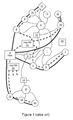
- FIG 1 illustrates a system in which an electric power and data network is provided for conveying electrical power and data to a plurality of subsea nodes.
- a host platform 4 provides power to the hubs 1, 2, 3.
- hub 1 provides data and electrical power to subsea wells 5, 6, 7 and is further connected to hub 2.
- Hub 2 provides electrical power and data to subsea wells 8, 9 and 10, and also provides electrical power and data services to subsea processing unit 11 and subsea environmental observatory 12.
- branching units 13, 14, 15 are also provided.
- a branching unit is effectively a cable splitter where a power cable is input and two or more power cables are output.
- the advantage of using branching units is that in the event of a fault or failure, individual portions of the electrical power/data network can be isolated without affecting the rest of the electrical power/data network. Further subsea wells are illustrated 16, 17, 18, 19, 20.
- hydraulic riser bases 21, 22 may be provided, and marginal prospects 23 may also be eventually connected to the electrical power/data network to further develop or evaluate them.
- the fluid conduit network illustrated by darker lines, is completely separate from the electrical power and data network (illustrated by the dotted lines).
- HVDC High Voltage Direct Current
- AC Alternating Current
- HVDC solution it is also preferred to feed the multiple electrical devices in series than in parallel, so as to reduce their operating voltage, and tolerate a cable shunt fault, as explained hereafter.
- a problem with providing DC power to a plurality of subsea nodes such as hubs is minimizing current leakage, and also maintaining service to the subsea nodes in the event of a shunt fault.
- a shunt fault typically occurs when the cable insulation becomes damaged (for example by a fishing vessel, anchor or undersea movements), and a short circuit occurs directly between the metallic core of the cable carrying power and the surrounding sea water.
- a shunt fault imposes null voltage at the fault location; it can be endured in operation by adapting the voltage at the power source so as to maintain the rated current, until the shunt fault can be repaired.
- FIG. 2 The most commonly used solution when providing power to a plurality of subsea nodes is illustrated in Figure 2 .
- a power supply 24 provides power to two subsea nodes 25, 26.
- the current is returned by the sea, through a sea electrode.
- a problem with this technique is that it can lead to corrosion of metallic equipment in the vicinity of the sea electrode.
- the electric current flows in a closed loop that is isolated from the sea. This overcomes the issue of corrosion in the vicinity of the sea electrode.
- a single conductor cable is used that forms a closed loop with each subsea node 25, 26 being fed in series. A problem with this arrangement is that it doubles the required length of cable, leading to increased costs in terms of the cable itself and laying the cable.
- a single cable is used for the power, but the power supply 24 cannot be referenced to earth. This means that measurements and control of the power supply are much more complicated than the examples of Figures 2 and 3 . It is not possible to reference the power supply 24 to earth because this would make the system intolerant to any shunt faults that develop,
- a system for transporting electric power to a subsea node comprising a first direct current power unit and a second direct current power unit.
- a referenced earth is operatively connected to the first and second power units and disposed between the first and second power units.
- a go and return cable comprising a go conductor connected to the first power unit and a return conductor is connected to the second power unit. The go conductor is operatively connected to the subsea node.
- the go and return cable is a coaxial cable comprising an inner core conductor and an outer conductor, the outer conductor being disposed radially around the inner conductor, wherein the inner core conductor is the go conductor and the outer conductor is the return conductor.
- the system optionally comprises a plurality of subsea nodes, each subsea node of the plurality of subsea nodes being operatively connected to the go conductor.
- the system is optionally provided with a current sensor disposed in proximity to the referenced earth, the current sensor arranged to detect a current leakage at a point in the go and return cable.
- the system may be provided with a first controller function operatively connected to the first power unit, the first controller function arranged to control a current carried by the go conductor to maintain a current provided to the subsea node.
- the system is provided with a second controller function operatively connected to the second power unit, the second controller function arranged to control a voltage across the second power unit such that, in the absence of a current leak in the return conductor, the voltage across the second power unit substantially matches a measured voltage across the first power unit.
- the voltage between the shunt fault and the second power unit is adjusted to compensate for a current leakage caused by the shunt fault.
- a method of compensating for a shunt fault in a go and return cable connected a subsea node to a power supply A first direct current power unit, a second direct current power unit, and a referenced earth connected to the first and second power units and disposed between the first and second power units are all provided.
- a go and return cable is also provided, which comprises a go conductor connected to the first power unit and a return conductor connected to the second power unit, wherein the go conductor is operatively connected to the subsea node.
- a voltage across the second power unit is controlled such that a current in the go conductor substantially matches a current in the return conductor.
- the voltage across the first and/or second power unit is adjusted to compensate for a current leakage caused by a shunt fault at the return conductor.
- the method optionally includes, prior to adjusting the voltage, detecting the shunt fault at the return conductor.
- the method includes determining an amount of voltage adjustment required to reduce the value of the current leakage caused by the shunt fault to substantially zero.
- the method optionally further comprises determining a value of the current leakage using a current measured at the referenced earth.
- a control device arranged to control power in a go and return cable.
- the control device is provided with a first functional interface for controlling a current provided by a first power unit.
- a second functional interface is provided for controlling a voltage across a second power unit, wherein the first power unit and the second power unit are connected to a go conductor and a return conductor respectively of a go and return cable, and a referenced earth is disposed between the first and second power supplies, the go conductor arranged to be operatively connected to at least one subsea node.
- a third functional interface is provided for receiving a measurement of a current at the referenced earth, the referenced earth current corresponding substantially with a value of a current leakage in the return conductor.
- a processor is used for determining the presence of a shunt fault in the return conductor using the measured current at the referenced earth.
- the processor is further arranged to instruct the second functional interface to adjust a voltage across the first and/or the second power unit to compensate for a current leakage caused by the shunt fault at the return conductor.
- the processor is arranged to determine an amount of voltage adjustment required to reduce the value of the current leakage caused by the shunt fault to substantially zero.
- a power supply for providing power to a subsea node.
- the power supply comprises a first direct current power unit, a second power direct current unit and a referenced earth operatively connected to the first and second power units and disposed between the first and second power units.
- the first power supply comprises a first connector for connecting to a go conductor of a go and return cable
- the second power supply comprises a second connector for connecting to a return conductor of the go and return cable
- the go conductor is connectable to the subsea node.
- the power supply further comprises a current sensor for measuring a current at the referenced earth.
- a computer program comprising computer readable code which, when run on a computer device, causes the computer device to perform the steps of:
- a computer program product comprising a non-transitory computer readable medium and a computer program as described above in the fifth aspect, wherein the computer program is stored on the computer readable medium.
- a power distribution system that includes a power supply that consists of two power units 27, 28 in series.
- a referenced earth 29 is disposed between the two power units 27, 28.
- One power unit 27 is used for the "go" path of a go and return cable 30, and the other power unit 28 is used for the "return” path of the cable.
- the go and return cable 30 carries power between the power supply and a plurality of subsea nodes 25, 26.
- the example of Figure 5 shows two subsea nodes 25, 26 but it will be appreciated that any number of subsea nodes could be connected using the go and return cable 30.
- the cable 30 is a go and return cable, so both the go path and the return path of the power supply are located in a single cable. This reduces the cost of the cable itself (as a double length is not required) and the costs associated with laying the cable.
- Each subsea node 25 26 is connected to the cable 30 on the go path.
- Shunt faults typically affect the return path, so any shunt faults are unlikely to affect power distribution to the subsea nodes 25, 25.
- the reason that shunt faults tend to affect the return path is that shunt faults are typically caused by physical trauma to the outside of the cable.
- a coaxial go and return cable has the go path of the cable 30 located in the centre (inner core) of the cable 30 and the return path of the cable 30 disposed radially around the go path (forming an outer core). As the return path of the cable 30 is closer to the outside of the cable, it is more likely to be physically damaged than the go path, so any shunt faults are likely to occur in the return path rather than the go path.
- Load balancing in the event of any current leaks can be performed by altering the voltage on the return power unit 28.
- the cable 30 does not need to be looped in the subsea power distribution network because power is provided using a coaxial cable.
- the go and return power supply consists of a go power unit 27 and a return power unit 28 with a reference to earth disposed between them, with one power unit 27 being positive and the other power unit 28 being negative.
- the combination of the go and return power supply and a go and return cable 30, allows the subsea nodes 25, 26 to be connected in series to the go and return cable 30. As the power unit is referenced to earth, there is no need to use a sea electrode.
- the go power unit 27 and the return power unit 28 are controlled to impose the same currents (termed Igo and Iret) on the go and return paths of the cable 30.
- Figure 6 illustrates the same system as Figure 5 , but with a shunt fault 30 that has developed on the return path of the cable 30.
- the go power unit 27 and the return power unit 28 each adapt their voltage (Vgo and Vret respectively).
- the go power unit 27 adapts its voltage Vgo to compensate for the go and return cable voltage drop from the go power unit 27 to the point of the shunt fault 31, and the return power unit 28 adapts its voltage Vret to compensate for the cable voltage drop between the shunt fault 31 and the return power unit 28. In this way the current leakage remains null.
- the shunt fault 31 does not affect the power supplied to the subsea nodes 25, 26, and because there is no sea electrode, there is no risk of corrosion of surrounding metallic elements.
- the go and return cable 30 is formed of two coaxial conductors, the "go" portion being the inner one.
- Each conductor is High Voltage (HV) insulated, for example up to 10 kV, with regard to the other conductor and to the sea.
- HV High Voltage
- Each subsea node 25, 26 is connected in series on the go path of the cable 30 only.
- the current leakage is detected using a sensor at the earth 29 of the power supply.
- the current leakage is substantially equal to that of the leakage caused by the shunt fault 31.
- the return power unit 28 is controlled in the voltage mode. In the absence of any measured current leakage, the return power unit 28 voltage reference is adjusted to remain substantially equal to a measured go power unit 27 voltage. This ensures that the power delivery is shared equally between the go power unit 27 and the return power unit 28.
- Vret Vret-opt
- Ileak 0.
- the return power unit 28 voltage reference can therefore be corrected. This leads to a significant difference between Vgo and Vret, and that ensures that the value of Ileak (essentially the current loss caused by the shunt fault) remains very low or almost null.
- Vgo becomes identical to the voltage drop between the go power unit 27 and the shunt fault 31
- Vret becomes identical to the voltage drop between the shunt fault 31 and the return power unit 28. As the loads vary, this equilibrium can be dynamically maintained.
- the shunt fault 31 would mean that subsea node 25 could be provided with the electrical power necessary to maintain normal operations, but subsea node 26 would not be able to maintain normal operations.
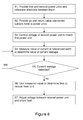
- Figure 8 is a flow diagram illustrating exemplary steps involved in compensating for a shunt fault in the return path of the cable 30. The following numbering corresponds to that of Figure 8 :
- Figure 9 illustrates schematically an exemplary computer device 32 for controlling current and voltage in the go and return cable.
- the computer device has a first interface 33 that is operatively connected to the first power unit 27 and can control the value of the electric current provided by the first power unit 27.
- a second interface 28 is also provided that is operatively connected to the second power unit 28 and can control the voltage between the second power unit 28 and the subsea nodes or a shunt fault 31.
- the interfaces are functional interfaces, and could be embodied, for example, in a single transceiver or a plurality of transmitters and receivers as appropriate.
- a third interface 35 is provided that receives measurements from a current sensor 36 disposed at the referenced earth 29. As described above, any current measured at the referenced earth 29 substantially corresponds to any leakage current Ileak caused by a shunt fault in the return path of the go and return cable 30.
- a processor 37 is provided for controlling operation of the computer device. It is arranged to maintain the voltage between the second power unit 28 and the subsea nodes 25, 26 at a value substantially the same as a measured voltage between the first power unit 27 and the subsea nodes 25, 26. In the event that a current is measured at the referenced earth by the sensor 36, the processor 37 determines that a shunt fault 31 is likely to exist in the return path of the go and return cable 30. It will be appreciated that different functions of the processor (such as determining that a shunt fault exists, or maintaining the voltage) may be implemented in a single processor or in a plurality of physical processors.
- the processor 37 determines a voltage value between the second power unit 28 and the shunt fault 31 that would effectively reduce the value of Ileak to zero, and instructs the second interface 34 to adjust the voltage Vret between the second power unit 28 and the shunt fault to substantially zero.
- the computer device may also be provided with a non-transitory computer readable medium in the form of a memory 38 which may be used to store a computer program 39.
- a computer program 38 When the computer program 38 is executed by the processor 37, it causes the processor to operate as described above.
- the computer program 38 may be stored on an external non-transitory computer readable medium 40 which can then be transferred to the first memory 38 or executed directly by the processor 37.
- Analogue circuits may be used to compensate for any shunt faults.
Abstract
A system for transporting electric power to a subsea node, the system comprising a first direct current power unit, a second direct current power unit, a referenced earth operatively connected to the first and second power units and disposed between the first and second power units, and a go and return cable comprising a go conductor connected to the first power unit and a return conductor connected to the second power unit, wherein the go conductor is operatively connected to the subsea node.
Description
- The invention relates to the field of providing electrical power to a subsea node.
- In subsea hydrocarbon production systems, a host production facility such as shore based production facility or an offshore platform is typically connected to one or more subsea wells. Production pipelines connect each subsea well to the host production facility. Production pipelines are used for conveying extracted hydrocarbons back to the host production facility. In addition to the production pipelines, it is necessary to provide each subsea well with certain services. These include electric power, data transfer, hydraulic fluids and wellstream service fluids, such as chemical additives. These four services are normally provided in one or more subsea umbilicals.
- Each subsea well has a subsea Christmas tree; a collection of valves and other fittings to control the flow out of the well and to control the injection of process fluids into the well. Christmas trees typically provide other functions, such as pressure relief, well intervention, acting as a point to connect other devices such as monitoring equipment.
- In known system, electrical power from the host production facility is provided to each Christmas tree (or other subsea structure) individually. Recently, some suggestions have been made to provide a subsea power network that can service many different subsea nodes. For example,
WO 2011/147459 describes a system in which an electric power and data network is provided for conveying electrical power and data to a plurality of subsea nodes. This is illustrated inFigure 1 , in which threehubs host platform 4 provides power to thehubs Figure 1 ,hub 1 provides data and electrical power to subseawells hub 2.Hub 2 provides electrical power and data to subseawells 8, 9 and 10, and also provides electrical power and data services tosubsea processing unit 11 and subseaenvironmental observatory 12. - In the example of
Figure 1 ,branching units - For the fluid conveying network,
hydraulic riser bases marginal prospects 23 may also be eventually connected to the electrical power/data network to further develop or evaluate them. - The fluid conduit network, illustrated by darker lines, is completely separate from the electrical power and data network (illustrated by the dotted lines).
- Owing to the distances over which power may be transmitted, it is preferred to use High Voltage Direct Current (HVDC) rather than Alternating Current (AC), as AC has a limited range before losses and the high charging current of AC become a problem. With the HVDC solution, it is also preferred to feed the multiple electrical devices in series than in parallel, so as to reduce their operating voltage, and tolerate a cable shunt fault, as explained hereafter.
- A problem with providing DC power to a plurality of subsea nodes such as hubs is minimizing current leakage, and also maintaining service to the subsea nodes in the event of a shunt fault. A shunt fault typically occurs when the cable insulation becomes damaged (for example by a fishing vessel, anchor or undersea movements), and a short circuit occurs directly between the metallic core of the cable carrying power and the surrounding sea water. A shunt fault imposes null voltage at the fault location; it can be endured in operation by adapting the voltage at the power source so as to maintain the rated current, until the shunt fault can be repaired.
- The most commonly used solution when providing power to a plurality of subsea nodes is illustrated in
Figure 2 . In the example ofFigure 2 , apower supply 24 provides power to twosubsea nodes - In the example of
Figures 3 and 4 , the electric current flows in a closed loop that is isolated from the sea. This overcomes the issue of corrosion in the vicinity of the sea electrode. In the example ofFigure 3 , a single conductor cable is used that forms a closed loop with eachsubsea node Figure 3 , a single cable is used for the power, but thepower supply 24 cannot be referenced to earth. This means that measurements and control of the power supply are much more complicated than the examples ofFigures 2 and 3 . It is not possible to reference thepower supply 24 to earth because this would make the system intolerant to any shunt faults that develop, - It is an object to provide a DC power supply to a plurality of subsea nodes that minimizes current leakage and also provides tolerance to shunt faults. According to a first aspect, there is provided a system for transporting electric power to a subsea node. The system comprises a first direct current power unit and a second direct current power unit. A referenced earth is operatively connected to the first and second power units and disposed between the first and second power units. A go and return cable comprising a go conductor connected to the first power unit and a return conductor is connected to the second power unit. The go conductor is operatively connected to the subsea node.
- As an option, the go and return cable is a coaxial cable comprising an inner core conductor and an outer conductor, the outer conductor being disposed radially around the inner conductor, wherein the inner core conductor is the go conductor and the outer conductor is the return conductor.
- The system optionally comprises a plurality of subsea nodes, each subsea node of the plurality of subsea nodes being operatively connected to the go conductor.
- The system is optionally provided with a current sensor disposed in proximity to the referenced earth, the current sensor arranged to detect a current leakage at a point in the go and return cable.
- The system may be provided with a first controller function operatively connected to the first power unit, the first controller function arranged to control a current carried by the go conductor to maintain a current provided to the subsea node. As a further option, the system is provided with a second controller function operatively connected to the second power unit, the second controller function arranged to control a voltage across the second power unit such that, in the absence of a current leak in the return conductor, the voltage across the second power unit substantially matches a measured voltage across the first power unit. In the event that a shunt fault is detected in the return conductor, the voltage between the shunt fault and the second power unit is adjusted to compensate for a current leakage caused by the shunt fault.
- According to a second aspect, there is provided a method of compensating for a shunt fault in a go and return cable connected a subsea node to a power supply. A first direct current power unit, a second direct current power unit, and a referenced earth connected to the first and second power units and disposed between the first and second power units are all provided. A go and return cable is also provided, which comprises a go conductor connected to the first power unit and a return conductor connected to the second power unit, wherein the go conductor is operatively connected to the subsea node. A voltage across the second power unit is controlled such that a current in the go conductor substantially matches a current in the return conductor. The voltage across the first and/or second power unit is adjusted to compensate for a current leakage caused by a shunt fault at the return conductor.
- The method optionally includes, prior to adjusting the voltage, detecting the shunt fault at the return conductor.
- As an option, the method includes determining an amount of voltage adjustment required to reduce the value of the current leakage caused by the shunt fault to substantially zero.
- The method optionally further comprises determining a value of the current leakage using a current measured at the referenced earth.
- According to a third aspect, there is provided a control device arranged to control power in a go and return cable. The control device is provided with a first functional interface for controlling a current provided by a first power unit. A second functional interface is provided for controlling a voltage across a second power unit, wherein the first power unit and the second power unit are connected to a go conductor and a return conductor respectively of a go and return cable, and a referenced earth is disposed between the first and second power supplies, the go conductor arranged to be operatively connected to at least one subsea node. A third functional interface is provided for receiving a measurement of a current at the referenced earth, the referenced earth current corresponding substantially with a value of a current leakage in the return conductor. A processor is used for determining the presence of a shunt fault in the return conductor using the measured current at the referenced earth. The processor is further arranged to instruct the second functional interface to adjust a voltage across the first and/or the second power unit to compensate for a current leakage caused by the shunt fault at the return conductor.
- As an option, the processor is arranged to determine an amount of voltage adjustment required to reduce the value of the current leakage caused by the shunt fault to substantially zero.
- According to a fourth aspect, there is provided a power supply for providing power to a subsea node. The power supply comprises a first direct current power unit, a second power direct current unit and a referenced earth operatively connected to the first and second power units and disposed between the first and second power units. The first power supply comprises a first connector for connecting to a go conductor of a go and return cable, the second power supply comprises a second connector for connecting to a return conductor of the go and return cable, and the go conductor is connectable to the subsea node.
- As an option, the power supply further comprises a current sensor for measuring a current at the referenced earth.
- According to a fifth aspect, there is provided a computer program comprising computer readable code which, when run on a computer device, causes the computer device to perform the steps of:
- controlling a current at a first power unit and a voltage at a second power unit, wherein the first power unit and the second power unit are connected to a go conductor and a return conductor respectively of a go and return cable, and a referenced earth is disposed between the first and second power supplies, the go conductor arranged to be operatively connected to at least one subsea node;
- determining a measurement of a current at the referenced earth, the referenced earth current corresponding substantially with a value of a current leakage in the return conductor;
- determining the presence of a shunt fault at the return conductor using the measured current at the referenced earth; and
- instructing an adjustment to a voltage across the first and/or the second power unit to compensate for a current leakage caused by the shunt fault at the return conductor.
- According to a sixth aspect, there is provided a computer program product comprising a non-transitory computer readable medium and a computer program as described above in the fifth aspect, wherein the computer program is stored on the computer readable medium.
-
-
Figure 1 illustrates schematically in a block diagram an exemplary subsea electrical power/data network and a separate fluid conveying network; -
Figure 2 illustrates schematically in a block diagram an exemplary subsea power distribution system to a plurality of subsea nodes using a sea electrode; -
Figure 3 illustrates schematically in a block diagram an exemplary closed loop subsea power distribution system; -
Figure 4 illustrates schematically in a block diagram an alternative exemplary closed loop subsea power distribution system; -
Figure 5 illustrates schematically in a block diagram an exemplary closed loop subsea power distribution system using a go and return cable and a go and return power supply; -
Figure 6 illustrates schematically in a block diagram an exemplary closed loop subsea power distribution system using a go and return cable and a go and return power supply and having a shunt fault; -
Figure 7 illustrates schematically in a block diagram a further exemplary closed loop subsea power distribution system using a go and return cable and a go and return power supply; -
Figure 8 is a flow diagram showing steps for detecting and compensating for a shunt fault in a go and return cable; and -
Figure 9 illustrates schematically in a block diagram an exemplary computer device. - Referring to
Figure 5 herein, there is illustrated a power distribution system that includes a power supply that consists of twopower units earth 29 is disposed between the twopower units power unit 27 is used for the "go" path of a go and returncable 30, and theother power unit 28 is used for the "return" path of the cable. The go and returncable 30 carries power between the power supply and a plurality ofsubsea nodes Figure 5 shows twosubsea nodes cable 30. - The
cable 30 is a go and return cable, so both the go path and the return path of the power supply are located in a single cable. This reduces the cost of the cable itself (as a double length is not required) and the costs associated with laying the cable. - Each
subsea node 25 26 is connected to thecable 30 on the go path. Shunt faults typically affect the return path, so any shunt faults are unlikely to affect power distribution to thesubsea nodes cable 30 located in the centre (inner core) of thecable 30 and the return path of thecable 30 disposed radially around the go path (forming an outer core). As the return path of thecable 30 is closer to the outside of the cable, it is more likely to be physically damaged than the go path, so any shunt faults are likely to occur in the return path rather than the go path. - Load balancing in the event of any current leaks can be performed by altering the voltage on the
return power unit 28. Thecable 30 does not need to be looped in the subsea power distribution network because power is provided using a coaxial cable. - The go and return power supply consists of a
go power unit 27 and areturn power unit 28 with a reference to earth disposed between them, with onepower unit 27 being positive and theother power unit 28 being negative. The combination of the go and return power supply and a go and returncable 30, allows thesubsea nodes cable 30. As the power unit is referenced to earth, there is no need to use a sea electrode. - The go
power unit 27 and thereturn power unit 28 are controlled to impose the same currents (termed Igo and Iret) on the go and return paths of thecable 30.Figure 6 illustrates the same system asFigure 5 , but with ashunt fault 30 that has developed on the return path of thecable 30. In this case, the current leakage Ileak is given byEquation 1.
- The go
power unit 27 and thereturn power unit 28 each adapt their voltage (Vgo and Vret respectively). The gopower unit 27 adapts its voltage Vgo to compensate for the go and return cable voltage drop from thego power unit 27 to the point of theshunt fault 31, and thereturn power unit 28 adapts its voltage Vret to compensate for the cable voltage drop between theshunt fault 31 and thereturn power unit 28. In this way the current leakage remains null. Theshunt fault 31 does not affect the power supplied to thesubsea nodes - Turning now to
Figure 6 , there is illustrated an exemplary subsea power distribution system. The go and returncable 30 is formed of two coaxial conductors, the "go" portion being the inner one. Each conductor is High Voltage (HV) insulated, for example up to 10 kV, with regard to the other conductor and to the sea. - Each
subsea node cable 30 only. - The current leakage, given by
Equation 1, is detected using a sensor at theearth 29 of the power supply. The current leakage is substantially equal to that of the leakage caused by theshunt fault 31. - The go
power unit 27 is controlled in the current mode so as to maintain the nominal current Inom required by thesubsea nodes 25, 26 (in other words, Igo = Inom). This ensures that the power to thesubsea nodes - The
return power unit 28 is controlled in the voltage mode. In the absence of any measured current leakage, thereturn power unit 28 voltage reference is adjusted to remain substantially equal to a measuredgo power unit 27 voltage. This ensures that the power delivery is shared equally between the gopower unit 27 and thereturn power unit 28. - When a current leakage, Ileak, is detected (indicating the presence of a shunt fault), the return current Iret is given by Equation 2:

- The
return power unit 28 is controlled in the voltage mode to correct the proportion of Ileak according to Equation 3:
- This equation allows the control to determine Vret, from the measurement of Vgo and Ileak. It will be appreciated that Vret may be determined in other ways in order to approach an optimal situation where Vgo = "Vgo-opt", Vret = "Vret-opt", Ileak = 0. Note that the control operates in a "close loop" mode, i.e. measuring a leakage current changes the voltages in such a way that the leakage current decreases. It will finally end up with Ileak = (Vret-opt - Vgo-opt)/k, as small as k is high (typically 0.1mA for a 1 kV correction, if k = 10 KV/mA).
- The
return power unit 28 voltage reference can therefore be corrected. This leads to a significant difference between Vgo and Vret, and that ensures that the value of Ileak (essentially the current loss caused by the shunt fault) remains very low or almost null. - In practice, Vgo becomes identical to the voltage drop between the go
power unit 27 and theshunt fault 31, and Vret becomes identical to the voltage drop between theshunt fault 31 and thereturn power unit 28. As the loads vary, this equilibrium can be dynamically maintained. - In the event that a severe shunt fault develops that affects both the go and the return path, system operation remains still possible but is limited to the subsea nodes located upstream from the fault. In the example of
Figure 7 , theshunt fault 31 would mean thatsubsea node 25 could be provided with the electrical power necessary to maintain normal operations, butsubsea node 26 would not be able to maintain normal operations. -
Figure 8 is a flow diagram illustrating exemplary steps involved in compensating for a shunt fault in the return path of thecable 30. The following numbering corresponds to that ofFigure 8 : - S1.
First power unit 27,second power unit 28 and referencedearth 28 are provided. - S2. Go and return cable is used to connect the
first power unit 27 to thesubsea nodes second power unit 28. - S3. In normal use, where there are no shunt faults in the return path of the go and return cable, the voltage between the second power unit and the subsea nodes is controlled to match a measured voltage between the first power unit and the subsea nodes.
- S4. A current sensor is used to measure the current at the referenced
earth 28. If a current is detected, this is evidence that a shunt fault has developed in the go and return cable. Owing to the coaxial structure of the go and return cable, the shunt fault is likely to be present in the return path of the go and return cable rather than the go path. - S5. If no current is detected, then measurements continue and the procedure reverts to step S4. If a current is detected, then a shunt fault is likely to exist and should be compensated for. The procedure continues at step S6.
- S6. The measured value of current at the referenced
earth 28 provides a good estimate of Ileak. This value is used to determine the required voltage between thesecond power unit 27 and theshunt fault 31 in order to reduce Ileak to substantially zero. - S7. The voltage between the
second power unit 27 and theshunt fault 31 is adjusted to reduce Ileak to substantially zero. -
Figure 9 illustrates schematically anexemplary computer device 32 for controlling current and voltage in the go and return cable. The computer device has afirst interface 33 that is operatively connected to thefirst power unit 27 and can control the value of the electric current provided by thefirst power unit 27. Asecond interface 28 is also provided that is operatively connected to thesecond power unit 28 and can control the voltage between thesecond power unit 28 and the subsea nodes or ashunt fault 31. Note that the interfaces are functional interfaces, and could be embodied, for example, in a single transceiver or a plurality of transmitters and receivers as appropriate. - A
third interface 35 is provided that receives measurements from acurrent sensor 36 disposed at the referencedearth 29. As described above, any current measured at the referencedearth 29 substantially corresponds to any leakage current Ileak caused by a shunt fault in the return path of the go and returncable 30. - A processor 37 is provided for controlling operation of the computer device. It is arranged to maintain the voltage between the
second power unit 28 and thesubsea nodes first power unit 27 and thesubsea nodes sensor 36, the processor 37 determines that ashunt fault 31 is likely to exist in the return path of the go and returncable 30. It will be appreciated that different functions of the processor (such as determining that a shunt fault exists, or maintaining the voltage) may be implemented in a single processor or in a plurality of physical processors. - If a shunt fault is detected, then the processor 37, as described above, determines a voltage value between the
second power unit 28 and theshunt fault 31 that would effectively reduce the value of Ileak to zero, and instructs thesecond interface 34 to adjust the voltage Vret between thesecond power unit 28 and the shunt fault to substantially zero. - The computer device may also be provided with a non-transitory computer readable medium in the form of a
memory 38 which may be used to store acomputer program 39. When thecomputer program 38 is executed by the processor 37, it causes the processor to operate as described above. Note also that thecomputer program 38 may be stored on an external non-transitory computer readable medium 40 which can then be transferred to thefirst memory 38 or executed directly by the processor 37. - Note that the computer device is not necessary in order to implement the techniques described above. Analogue circuits may be used to compensate for any shunt faults.
- It will be appreciated by a person of skill in the art that various modifications may be made to the embodiments described above without departing from the scope of the present disclosure.
- The following abbreviations have been used in the above description:
- AC
- Alternating Current
- DC
- Direct Current
- HVDC
- High Voltage Direct Current
- LVDC
- Low Voltage Direct Current
Claims (16)
- A system for transporting electric power to a subsea node, the system comprising:a first direct current power unit;a second direct current power unit;a referenced earth operatively connected to the first and second power units and disposed between the first and second power units;a go and return cable comprising a go conductor connected to the first power unit and a return conductor connected to the second power unit, wherein the go conductor is operatively connected to the subsea node.
- The system according to claim 1, wherein the go and return cable is a coaxial cable comprising an inner core conductor and an outer conductor, the outer conductor being disposed radially around the inner conductor, wherein the inner core conductor is the go conductor and the outer conductor is the return conductor.
- The system according to claim 1 or claim 2, further comprising a plurality of subsea nodes, each subsea node of the plurality of subsea nodes being operatively connected to the go conductor.
- The system according to any one of claims 1, 2 or 3, further comprising a current sensor disposed in proximity to the referenced earth, the current sensor arranged to detect a current leakage at a point in the go and return cable.
- The system according to any one of the preceding claims, further comprising:a first controller function operatively connected to the first power unit, the first controller function arranged to control a current carried by the go conductor to maintain a current provided to the subsea node.
- The system according to claim 5, further comprising a second controller function operatively connected to the second power unit, the second controller function arranged to control a voltage across the second power unit such that, in the absence of a current leak in the return conductor, the voltage across the second power unit substantially matches a measured voltage across the first power unit and, in the event that a shunt fault is detected in the return conductor, the voltage between the shunt fault and the second power unit is adjusted to compensate for a current leakage caused by the shunt fault.
- A method of compensating for a shunt fault in a go and return cable connected a subsea node to a power supply, the method comprising:providing a first direct current power unit, a second direct current power unit, and a referenced earth connected to the first and second power units and disposed between the first and second power units;providing a go and return cable comprising a go conductor connected to the first power unit and a return conductor connected to the second power unit, wherein the go conductor is operatively connected to the subsea node;controlling a voltage across the second power unit such that a current in the go conductor substantially matches a current in the return conductor; andadjusting a voltage across the first and/or the second power unit to compensate for a current leakage caused by a shunt fault at the return conductor.
- The method according to claim 7, further comprising prior to adjusting the voltage, detecting the shunt fault at the return conductor.
- The method according to claim 7 or 8, further comprising:determining an amount of voltage adjustment required to reduce the value of the current leakage caused by the shunt fault to substantially zero.
- The method according to any one of claims 7, 8 or 9, further comprising determining a value of the current leakage using a current measured at the referenced earth.
- A control device arranged to control power in a go and return cable, the control device comprising:a first functional interface for controlling a current provided by a first power unit;a second functional interface for controlling a voltage across a second power unit, wherein the first power unit and the second power unit are connected to a go conductor and a return conductor respectively of a go and return cable, and a referenced earth is disposed between the first and second power supplies, the go conductor arranged to be operatively connected to at least one subsea node;a third functional interface for receiving a measurement of a current at the referenced earth, the referenced earth current corresponding substantially with a value of a current leakage in the return conductor;a processor for determining the presence of a shunt fault in the return conductor using the measured current at the referenced earth;the processor being further arranged to instruct the second functional interface to adjust a voltage across the first and/or the second power unit to compensate for a current leakage caused by the shunt fault at the return conductor.
- The control device according to claim 11, wherein the processor is arranged to determine an amount of voltage adjustment required to reduce the value of the current leakage caused by the shunt fault to substantially zero.
- A power supply for providing power to a subsea node, the power supply comprising:a first direct current power unit;a second power direct current unit;a referenced earth operatively connected to the first and second power units and disposed between the first and second power units;wherein the first power supply comprises a first connector for connecting to a go conductor of a go and return cable, the second power supply comprises a second connector for connecting to a return conductor of the go and return cable, the go conductor being connectable to the subsea node.
- The power supply according to claim 13, further comprising a current sensor for measuring a current at the referenced earth.
- A computer program comprising computer readable code which, when run on a computer device, causes the computer device to perform the steps of:controlling a current at a first power unit and a voltage at a second power unit, wherein the first power unit and the second power unit are connected to a go conductor and a return conductor respectively of a go and return cable, and a referenced earth is disposed between the first and second power supplies, the go conductor arranged to be operatively connected to at least one subsea node;determining a measurement of a current at the referenced earth, the referenced earth current corresponding substantially with a value of a current leakage in the return conductor;determining the presence of a shunt fault at the return conductor using the measured current at the referenced earth; andinstructing an adjustment to a voltage across the first and/or the second power unit to compensate for a current leakage caused by the shunt fault at the return conductor.
- A computer program product comprising a non-transitory computer readable medium and a computer program according to claim 15, wherein the computer program is stored on the computer readable medium.
Priority Applications (2)
| Application Number | Priority Date | Filing Date | Title |
|---|---|---|---|
| EP13306248.9A EP2848762A1 (en) | 2013-09-11 | 2013-09-11 | Providing power to a subsea node |
| PCT/EP2014/069398 WO2015036483A1 (en) | 2013-09-11 | 2014-09-11 | Providing power to a subsea node |
Applications Claiming Priority (1)
| Application Number | Priority Date | Filing Date | Title |
|---|---|---|---|
| EP13306248.9A EP2848762A1 (en) | 2013-09-11 | 2013-09-11 | Providing power to a subsea node |
Publications (1)
| Publication Number | Publication Date |
|---|---|
| EP2848762A1 true EP2848762A1 (en) | 2015-03-18 |
Family
ID=49261476
Family Applications (1)
| Application Number | Title | Priority Date | Filing Date |
|---|---|---|---|
| EP13306248.9A Withdrawn EP2848762A1 (en) | 2013-09-11 | 2013-09-11 | Providing power to a subsea node |
Country Status (2)
| Country | Link |
|---|---|
| EP (1) | EP2848762A1 (en) |
| WO (1) | WO2015036483A1 (en) |
Cited By (1)
| Publication number | Priority date | Publication date | Assignee | Title |
|---|---|---|---|---|
| CN111817245A (en) * | 2019-04-12 | 2020-10-23 | 萨伯康姆有限责任公司 | Branching unit for power distribution |
Families Citing this family (1)
| Publication number | Priority date | Publication date | Assignee | Title |
|---|---|---|---|---|
| CN112186730B (en) * | 2020-08-12 | 2022-08-02 | 浙江大学 | Constant-current electric energy conversion system with stepless power regulation |
Citations (7)
| Publication number | Priority date | Publication date | Assignee | Title |
|---|---|---|---|---|
| WO2001067466A1 (en) * | 2000-03-09 | 2001-09-13 | Expro North Sea Limited | In-well monitoring and flow control system |
| WO2001084689A1 (en) * | 2000-04-28 | 2001-11-08 | Aker Engineering As | Distribution system for electrical power |
| WO2005111484A2 (en) * | 2004-04-30 | 2005-11-24 | Cameron International Corporation | Electric control and supply system |
| EP1870978A2 (en) * | 2006-06-23 | 2007-12-26 | Delphi Technologies, Inc. | Electrical distribution box |
| US20090167086A1 (en) * | 2007-12-31 | 2009-07-02 | Eric Seymour | System, method and apparatus for providing direct current |
| US20100288493A1 (en) * | 2009-05-18 | 2010-11-18 | Fielder Lance I | Cable suspended pumping system |
| WO2011147459A1 (en) | 2010-05-28 | 2011-12-01 | Statoil Asa | Subsea hydrocarbon production system |
Family Cites Families (4)
| Publication number | Priority date | Publication date | Assignee | Title |
|---|---|---|---|---|
| US8189306B2 (en) * | 2009-03-13 | 2012-05-29 | Raytheon Company | Dynamic grounding system and method |
| US8400744B2 (en) * | 2010-05-19 | 2013-03-19 | Schneider Electric USA, Inc. | Earth leakage detection module with robust transient suppression |
| EP2643913B1 (en) * | 2010-11-22 | 2018-07-25 | Saab AB | Power supply arrangement for distribution of power |
| US8941956B2 (en) * | 2011-07-26 | 2015-01-27 | Railpower, Llc | Switching ground tether circuit |
-
2013
- 2013-09-11 EP EP13306248.9A patent/EP2848762A1/en not_active Withdrawn
-
2014
- 2014-09-11 WO PCT/EP2014/069398 patent/WO2015036483A1/en active Application Filing
Patent Citations (7)
| Publication number | Priority date | Publication date | Assignee | Title |
|---|---|---|---|---|
| WO2001067466A1 (en) * | 2000-03-09 | 2001-09-13 | Expro North Sea Limited | In-well monitoring and flow control system |
| WO2001084689A1 (en) * | 2000-04-28 | 2001-11-08 | Aker Engineering As | Distribution system for electrical power |
| WO2005111484A2 (en) * | 2004-04-30 | 2005-11-24 | Cameron International Corporation | Electric control and supply system |
| EP1870978A2 (en) * | 2006-06-23 | 2007-12-26 | Delphi Technologies, Inc. | Electrical distribution box |
| US20090167086A1 (en) * | 2007-12-31 | 2009-07-02 | Eric Seymour | System, method and apparatus for providing direct current |
| US20100288493A1 (en) * | 2009-05-18 | 2010-11-18 | Fielder Lance I | Cable suspended pumping system |
| WO2011147459A1 (en) | 2010-05-28 | 2011-12-01 | Statoil Asa | Subsea hydrocarbon production system |
Cited By (1)
| Publication number | Priority date | Publication date | Assignee | Title |
|---|---|---|---|---|
| CN111817245A (en) * | 2019-04-12 | 2020-10-23 | 萨伯康姆有限责任公司 | Branching unit for power distribution |
Also Published As
| Publication number | Publication date |
|---|---|
| WO2015036483A1 (en) | 2015-03-19 |
Similar Documents
| Publication | Publication Date | Title |
|---|---|---|
| US9151794B2 (en) | Fault detection system and method, and power system for subsea pipeline direct electrical heating cables | |
| US9121231B2 (en) | Subsea hydrocarbon production system | |
| EP1992954B1 (en) | Method for determining location of phase-to-earth fault | |
| CN104297627B (en) | For controlling and protecting the method and system of direct current subsea power system | |
| CN101576430B (en) | Leakage detection equipment | |
| JP2015148610A (en) | Method and system for determining location of fault in ungrounded power distribution system | |
| US11555843B2 (en) | Method and system for localizing a short circuit between a conductor and an electrically conductive shield surrounding said conductor | |
| EP2848762A1 (en) | Providing power to a subsea node | |
| US10180696B2 (en) | Distributed impedance injection module for mitigation of the Ferranti effect | |
| NO20200471A1 (en) | Subsea hydrocarbon production system | |
| EP2402774A1 (en) | Method and apparatus for determining distance to phase-to-earth fault | |
| US20180358888A1 (en) | Improvements in or relating to converters | |
| NO332207B1 (en) | Method and apparatus for fault analysis and redundancy switching in an energy supply for an instrumented towed cable in water | |
| US20160053587A1 (en) | Subsea electrical unit and system | |
| US20150198651A1 (en) | Test Arrangement | |
| CN111527661B (en) | Fault location in multi-terminal tapped lines | |
| WO2016034938A1 (en) | Communication distribution unit containing at least one power switch | |
| NO20160575A1 (en) | Voltage Regulation for a Subsea Control System | |
| RU2607487C1 (en) | Underwater hydrocarbon production system | |
| AU2015203041B2 (en) | Subsea hydrocarbon production system | |
| RU2604603C1 (en) | Underwater hydrocarbon production system | |
| BR112015027852B1 (en) | SUBSEA ELECTRICAL UNIT AND SYSTEM, AND METHOD FOR OPERATING A SUBSEA ELECTRICAL UNIT |
Legal Events
| Date | Code | Title | Description |
|---|---|---|---|
| PUAI | Public reference made under article 153(3) epc to a published international application that has entered the european phase |
Free format text: ORIGINAL CODE: 0009012 |
|
| 17P | Request for examination filed |
Effective date: 20130911 |
|
| AK | Designated contracting states |
Kind code of ref document: A1 Designated state(s): AL AT BE BG CH CY CZ DE DK EE ES FI FR GB GR HR HU IE IS IT LI LT LU LV MC MK MT NL NO PL PT RO RS SE SI SK SM TR |
|
| AX | Request for extension of the european patent |
Extension state: BA ME |
|
| STAA | Information on the status of an ep patent application or granted ep patent |
Free format text: STATUS: THE APPLICATION IS DEEMED TO BE WITHDRAWN |
|
| 18D | Application deemed to be withdrawn |
Effective date: 20150919 |