EP2845189B1 - A universal reconfigurable echo cancellation system - Google Patents
A universal reconfigurable echo cancellation system Download PDFInfo
- Publication number
- EP2845189B1 EP2845189B1 EP13784615.0A EP13784615A EP2845189B1 EP 2845189 B1 EP2845189 B1 EP 2845189B1 EP 13784615 A EP13784615 A EP 13784615A EP 2845189 B1 EP2845189 B1 EP 2845189B1
- Authority
- EP
- European Patent Office
- Prior art keywords
- echo
- signal
- output signal
- residual
- nonlinear
- Prior art date
- Legal status (The legal status is an assumption and is not a legal conclusion. Google has not performed a legal analysis and makes no representation as to the accuracy of the status listed.)
- Active
Links
- 238000012545 processing Methods 0.000 claims description 44
- 230000003044 adaptive effect Effects 0.000 claims description 34
- 238000000034 method Methods 0.000 claims description 32
- 230000001629 suppression Effects 0.000 claims description 23
- 230000002265 prevention Effects 0.000 claims description 18
- 230000008569 process Effects 0.000 claims description 17
- 238000001914 filtration Methods 0.000 claims description 10
- 238000004590 computer program Methods 0.000 claims description 4
- 238000010586 diagram Methods 0.000 description 29
- 230000009467 reduction Effects 0.000 description 7
- 238000012546 transfer Methods 0.000 description 6
- 230000006978 adaptation Effects 0.000 description 5
- 230000000694 effects Effects 0.000 description 5
- 230000004044 response Effects 0.000 description 5
- 238000004891 communication Methods 0.000 description 4
- 230000006870 function Effects 0.000 description 4
- 208000019300 CLIPPERS Diseases 0.000 description 2
- 238000013459 approach Methods 0.000 description 2
- 230000003139 buffering effect Effects 0.000 description 2
- 238000004364 calculation method Methods 0.000 description 2
- 208000021930 chronic lymphocytic inflammation with pontine perivascular enhancement responsive to steroids Diseases 0.000 description 2
- 238000005516 engineering process Methods 0.000 description 2
- 241001237259 Campanella <basidiomycete fungus> Species 0.000 description 1
- 101000802640 Homo sapiens Lactosylceramide 4-alpha-galactosyltransferase Proteins 0.000 description 1
- 102100035838 Lactosylceramide 4-alpha-galactosyltransferase Human genes 0.000 description 1
- 241000699670 Mus sp. Species 0.000 description 1
- 241000949477 Toona ciliata Species 0.000 description 1
- 230000008859 change Effects 0.000 description 1
- 238000013500 data storage Methods 0.000 description 1
- 238000001514 detection method Methods 0.000 description 1
- 238000011161 development Methods 0.000 description 1
- 238000002592 echocardiography Methods 0.000 description 1
- 238000010348 incorporation Methods 0.000 description 1
- 230000010354 integration Effects 0.000 description 1
- 230000007246 mechanism Effects 0.000 description 1
- 238000012986 modification Methods 0.000 description 1
- 230000004048 modification Effects 0.000 description 1
- 230000000717 retained effect Effects 0.000 description 1
- 230000005236 sound signal Effects 0.000 description 1
- 230000003595 spectral effect Effects 0.000 description 1
Images


Classifications
-
- H—ELECTRICITY
- H04—ELECTRIC COMMUNICATION TECHNIQUE
- H04M—TELEPHONIC COMMUNICATION
- H04M3/00—Automatic or semi-automatic exchanges
- H04M3/002—Applications of echo suppressors or cancellers in telephonic connections
-
- G—PHYSICS
- G10—MUSICAL INSTRUMENTS; ACOUSTICS
- G10L—SPEECH ANALYSIS TECHNIQUES OR SPEECH SYNTHESIS; SPEECH RECOGNITION; SPEECH OR VOICE PROCESSING TECHNIQUES; SPEECH OR AUDIO CODING OR DECODING
- G10L21/00—Speech or voice signal processing techniques to produce another audible or non-audible signal, e.g. visual or tactile, in order to modify its quality or its intelligibility
- G10L21/02—Speech enhancement, e.g. noise reduction or echo cancellation
- G10L21/0208—Noise filtering
-
- H—ELECTRICITY
- H04—ELECTRIC COMMUNICATION TECHNIQUE
- H04B—TRANSMISSION
- H04B3/00—Line transmission systems
- H04B3/02—Details
- H04B3/20—Reducing echo effects or singing; Opening or closing transmitting path; Conditioning for transmission in one direction or the other
-
- H—ELECTRICITY
- H04—ELECTRIC COMMUNICATION TECHNIQUE
- H04M—TELEPHONIC COMMUNICATION
- H04M9/00—Arrangements for interconnection not involving centralised switching
- H04M9/08—Two-way loud-speaking telephone systems with means for conditioning the signal, e.g. for suppressing echoes for one or both directions of traffic
- H04M9/082—Two-way loud-speaking telephone systems with means for conditioning the signal, e.g. for suppressing echoes for one or both directions of traffic using echo cancellers
-
- G—PHYSICS
- G10—MUSICAL INSTRUMENTS; ACOUSTICS
- G10L—SPEECH ANALYSIS TECHNIQUES OR SPEECH SYNTHESIS; SPEECH RECOGNITION; SPEECH OR VOICE PROCESSING TECHNIQUES; SPEECH OR AUDIO CODING OR DECODING
- G10L21/00—Speech or voice signal processing techniques to produce another audible or non-audible signal, e.g. visual or tactile, in order to modify its quality or its intelligibility
- G10L21/02—Speech enhancement, e.g. noise reduction or echo cancellation
- G10L21/0208—Noise filtering
- G10L2021/02082—Noise filtering the noise being echo, reverberation of the speech
-
- H—ELECTRICITY
- H04—ELECTRIC COMMUNICATION TECHNIQUE
- H04B—TRANSMISSION
- H04B3/00—Line transmission systems
- H04B3/02—Details
- H04B3/20—Reducing echo effects or singing; Opening or closing transmitting path; Conditioning for transmission in one direction or the other
- H04B3/23—Reducing echo effects or singing; Opening or closing transmitting path; Conditioning for transmission in one direction or the other using a replica of transmitted signal in the time domain, e.g. echo cancellers
Definitions
- the present invention relates to processing signals. More particularly, the present invention relates to a system and method for processing signals to reduce echo or noise.
- goals of this invention include addressing the above problems by providing an effective and robust echo cancellation system and its real-time implementation.
- US7672445 discloses techniques for suppressing large echo due to non-linearity and unstable adaptive filters.
- this invention proposes an effective, simple and robust echo cancellation (EC) scheme with good audio quality and double talk performance. More importantly, the proposed scheme can automatically reconfigure in real-time the system settings, processing structures and parameters to deal with any practical application environment while continually maintaining good performance.
- EC echo cancellation
- a system for processing signals includes an echo cancellation processing module, a nonlinear echo processing module, and an echo leakage prevention module.
- the echo cancellation linear processing module is operable to generate a first output signal by adaptively filtering an input signal.
- the echo cancellation linear processing module comprises an echo cancellation operator for generating a residual echo signal by subtracting an estimated echo signal from the input signal, and a first complex adaptive filter configured for generating a first estimated echo signal based on a first reference signal and the residual echo signal, wherein the estimated echo signal is the first estimated echo signal.
- the first output signal is the input signal with any linear echo reduced.
- the nonlinear echo processing module is operable to generate a second output signal based on the first output signal.
- the nonlinear echo processing module comprises a nonlinear echo determination module configured for determining whether nonlinear echo is present in the first output signal, a nonlinear echo gain module configured for assigning a nonlinear echo gain for reducing nonlinear echo based on whether nonlinear echo is present in the first output signal; and a nonlinear echo operator configured for applying the nonlinear echo gain to the first output signal in generating the second output signal.
- the second output signal is the first output signal with any residual linear echo or nonlinear echo reduced.
- the echo leakage prevention module is operable to generate a third output signal based on the second output signal.
- the echo leakage prevention module comprises an echo leakage determination module configured for determining whether a root mean square value of the input signal is below a minimum input threshold, an echo leakage gain module configured for assigning an echo leakage gain for reducing echo leakage based on whether the root mean square value of the input signal is below the minimum input threshold and an echo leakage operator configured for applying the echo leakage gain to the second output signal in generating the third output signal.
- the third output signal is the second output signal with echo leakage reduced.
- the system may include a first residual echo suppression module operable to generate a fourth output signal based on the third output signal with any additional residual echo reduced.
- the system may also include a second residual echo suppression module operable to generate a fifth output signal based on the fourth output signal with any additional residual echo reduced.
- the first residual echo suppression module is based in the time-domain and the second residual echo suppression module is based in the frequency-domain.
- the system may include a HPF operable to reduce low frequency residual echo or noise. The HPF is typically positioned inline with the input signal.
- a method for an echo cancellation system to process signals includes: 1) generating a first output signal by adaptively filtering an input signal such that the first output signal is the input signal with any linear echo reduced, by generating a residual echo signal by subtracting an estimated echo signal from the input signal and generating a first estimated echo signal based on a first reference signal, the residual echo signal, and filter weights, wherein the estimated echo signal is the first estimated echo signal, and wherein the filter weights are updated automatically by coherence values based on the input signal and the first reference signal in real time; 2) generating a second output signal based on the first output signal such that the second output signal is the first output signal with any residual linear echo or nonlinear echo reduced by determining whether nonlinear echo is present in the first output signal, assigning a nonlinear echo gain for reducing nonlinear echo based on whether nonlinear echo is present in the first output signal, and applying the nonlinear echo gain to the first output signal in generating the second output signal; and
- the nonlinear echo caused by the nonlinearity, instable adaptive filter, and so on can be effectively reduced.
- the proposed nonlinear processors NLPs
- the residual echo can be greatly reduced so as to avoid the howling effect which is highly undesired.
- the proposed echo leakage prevention the system output will not result in echo caused by the linear EC unit when the microphone is taken off or muted in the acoustic echo cancellation (AEC) system.
- each unit is independent of the levels of the input audio signal and the EC reference signal.
- the proposed scheme can provide the users with good audio quality, good full-duplex performance, and an effective solution for any acoustic EC and electrical EC applications.
- the invention extends to a machine readable medium embodying a sequence of instructions that, when executed by a machine, cause the machine to carry out any of the methods described herein.
- Hands-free communication systems, speakerphones, laptops with internal or external speakers, and videoconference setting-ups involve the use of loudspeakers and microphones. They allow users to talk more naturally without using a handset. This new type of use leads to new problems, namely the superposition of acoustical echo presented together with the target speech signal. It results in the other site hearing his/her own voice with a delay, but will not be noticed at the local site.
- Electrical echo may also be caused by signal reflection in a hybrid circuit that converts between 4-wire and 2-wire circuits. Users in this situation will also hear their own voice with a delay which is very annoying.
- FIG. 1 is a schematic block diagram illustrating a conventional system for acoustic echo cancellation.
- Conventional system 100 includes a linear processing module 110 and a nonlinear processing module 112 as shown in Figure 1 .
- a Delay 118 typically compensates for the pure delay resulting from a digital to analog (D/A) converter (not shown), the distance between the microphone 103 and the loudspeaker 107, buffering scheme, and an analog to digital (A/D) converter (not shown).
- An adaptive linear filter 116 attempts to model the transfer function between the loudspeaker signal 108 and the microphone signal 102.
- the adaptive linear filter 116 constantly monitors the transfer function and tracks changes in the acoustic echo path 109 with commonly employed least mean-squared (LMS) based algorithms.
- LMS least mean-squared
- the adaptive linear filter 116 can be implemented in either time domain (TD) or frequency-domain (FD).
- the output 122 of the adaptive linear filter 116 is very close to the echo portion of the microphone signal 102. Subtracting the adaptive linear filter output 122 from the microphone signal 102 reduces the echo. Since there is always a residual echo after the linear adaptive subtraction due to the fact that the adaptive linear filter 116 can neither be 100% accurate nor exactly model the transfer function, the nonlinear processing module 112 implements a nonlinear processor (NLP) technique that is necessary to further reduce the residual echo.
- NLP nonlinear processor
- the adaptive linear filter 116 would not be able to remove the nonlinear echo caused by any instability of the adaptive filter and non-linearity in the AEC system 100 circuitry, such as from the loudspeaker 107, A/D converter, D/A converter due to an overdriven speaker, microphone saturation, mechanical vibration, and so on.
- the linear adaptive filter 116 would not have exactly zero values for all the filter weights, which will result in the echo at the output and is a kind of echo leakage problem. Similarly, this condition occurs in the electrical EC system for the case of no electrical echo.
- an echo cancellation system includes (1) an adaptive linear filter implemented in either time-domain or frequency-domain; (2) a nonlinear echo suppression; (3) echo leakage prevention; (4) direct current (DC), low frequency residual echo and noise reduction; (5) time-domain nonlinear processor (NLP) to reduce the residual echo; and (6) frequency-domain NLP to further reduce the residual echo.
- the echo cancellation system is universally applicable to acoustic echo cancellation (AEC) and/or electrical echo cancellation applications.
- AEC acoustic echo cancellation
- this invention is reconfigurable for one or more microphones and/or one or more reference channels. The numbers of microphones and reference channels are user configurable.
- FIG. 2 is a schematic block diagram illustrating a system 200 for acoustic echo cancellation according to various embodiments of the present invention.
- Fig.2 shows an application setting of AEC system 200.
- System 200 includes components such as a converter 212, loudspeaker 207, microphone 203, converter 210, AEC processor 214, and wired or wireless network/circuitry interconnecting the various system components.
- Converter 212 is configured for receiving a signal 206 from a network coupled to a far-end (remote) site, converting signal 206 with converter 212 (e.g., D/A converter), and outputting a converted signal 208 of signal 206 to loudspeaker 207 for reproduction at a near-end (local) site.
- converter 212 e.g., D/A converter
- the reproduced converted signal 208 includes an acoustic echo along acoustic echo path 209.
- Microphone 203 is configured for receiving the acoustic echo along acoustic echo path 209 and outputting it as a microphone signal 202 to converter 210.
- Converter 210 is configured for receiving microphone signal 202, converting microphone signal 202 with converter 210 (e.g., A/D converter), and outputting a converted signal of microphone signal 202 to AEC processor 214.
- AEC processor 214 may include any portion of conventional linear processing module 110, conventional nonlinear processing module 112, and any other improvements discussed herein (e.g., See Figures 4 and 5 for further details).
- AEC processor 214 is configured for generating and outputting an acoustic echo-suppressed voice signal 204 to the network coupled to the far-end (remote) site. Acoustic echo-suppressed voice signal 204 is generated based on the converted microphone signal 202 of the acoustic echo along acoustic echo path 209 and an AEC reference signal (e.g., signal 206).
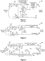
- FIG. 3 is a schematic block diagram illustrating a system 300 for acoustic and electrical echo cancellations according to various embodiments of the present invention.
- Fig. 3 shows the application setting of acoustic and electrical echo cancellations system 300.
- System 300 includes similar components as System 200 such as a converter 212, loudspeaker 207, microphone 203, converter 210, AEC processor 214, and wired or wireless network/circuitry interconnecting the various system components.
- System 300 also includes a local/line/electrical echo cancellation (LEC) processor 316. Similar to AEC processor 214, LEC processor 316 may include any portion of conventional linear processing module 110, conventional nonlinear processing module 112, and any other improvements discussed herein (e.g., See Figures 4 and 5 for further details).
- LEC local/line/electrical echo cancellation
- LEC processor 316 is configured for generating and outputting a local echo-suppressed far-end voice signal 320 to converter 212 and as the AEC reference to AEC processor 214.
- Local echo-suppressed far-end voice signal 320 is generated based on a signal 306 representative of the electrical echo along electrical echo path 305 and a LEC reference signal 318.
- LEC reference signal 318 is an acoustic echo-suppressed voice signal 304 generated from AEC Processor 214 to the network coupled to the far-end (remote) site.
- the proposed "nonlinear echo suppression" component applies for AEC while the rest of the components apply for both AEC and LEC. Therefore, the present invention relates more specifically to the techniques for AEC.
- FIG. 4 is a schematic block diagram illustrating a system 400 for acoustic echo cancellation according to various embodiments of the present invention.
- the proposed system 400 mainly includes six processing units: (1) AEC Linear Processing 410, i.e., an adaptive linear filter (See Sec. 2.1 and Figures 6, 7 , and 8 for further details); (2) nonlinear echo suppression 412 (See Sec. 2.2 and Figure 9 for further details); (3) echo leakage prevention 414 (See Sec. 2.3 and Figure 10 for further details); (4) high pass filter (HPF) 416, i.e., low frequency residual echo and noise reduction (See Sec. 2.4 and Figures 11 and 12 for further details); (5) TD REC 418, i.e., time-domain residual echo suppression (See Sec.
- AEC Linear Processing 410 i.e., an adaptive linear filter (See Sec. 2.1 and Figures 6, 7 , and 8 for further details);
- nonlinear echo suppression 412 See Sec. 2.2 and Figure 9 for further details
- FD REC 420 i.e., frequency-domain residual echo suppression (See Sec. 2.6 for further details).
- any combination of the six processing units may be used depending on the specific application. That is, any of the six processing units may be included, omitted, or reordered depending on the application.
- Sin 402 and Rin 406 are the inputs to the AEC system 400 whereas Sout 404 and Rout 408 are the outputs of the AEC system 400.
- the send path is from Sin 402 to Sout 404 and the receive path is from Rin 406 to Rout 408.
- Sin 402 is the microphone signal (e.g., 202) which includes near-end (NE) voice, NE environment noise, and acoustic echo.
- Rin 406 e.g., 206, 306) is the far-end (FE) voice, i.e., input of the receive path.
- Sout 404 e.g., 204, 304) is the echo-suppressed signal sent to the network for FE people to listen to.
- Rout 408 goes to the NE loudspeaker (e.g., 207) for NE people to listen to.
- FD REC 420 is configured for "50% STFT", which means short-time Fourier transform (STFT) with input 50% overlap.
- FIG. 5 is a schematic block diagram illustrating a system 500 for acoustic echo cancellation with integrated noise reduction according to various embodiments of the present invention.
- System 500 includes similar elements as those in system 400.
- elements 502, 504, 506, 508, 510, 511, 512, 514, 516, 518, 520 are similar to elements 402, 404, 406, 408, 410, 411, 412, 414, 416, 418, 420.
- this proposed AEC system 500 has been integrated with a noise reduction (NR) technology such as FD NR 522, which is a frequency-domain NR.
- NR noise reduction
- System 400 or 500 can be incorporated into either system 200 or 300, especially in AEC Processor 214 and/or LEC 316 Processor, and modified accordingly to their specific application. It will be appreciated by those skilled in the art that any combination of the seven processing units in system 500 may be used depending on the specific application.
- AEC Linear Processing (e.g., 410, 510) includes an adaptive linear filter that can be implemented in either time-domain or frequency-domain.
- Figure 6 is a schematic block diagram illustrating a system/module 600 for frequency-domain adaptive linear filtering according to various embodiments of the present invention.
- An example of the FD least mean-squared (LMS) based algorithms is shown as in Figure 6 .
- STFT 610 and ISTFT 622 denote short-time Fourier transform and inverse STFT, respectively.
- Delay 618 compensates for any pure delay resulting from one or more of the following factors: a D/A converter (e.g., 212), the distance between the microphone (e.g., 203) and the loudspeaker (e.g., 207), buffering scheme, and an A/D converter (e.g., 210).
- the frequency domain (FD) filtering i.e., Complex Adaptive Filter 616, is implemented by a complex multiply.
- the index n and k are for sample index and the frame index, respectively.
- the output of the FD filtering, Y(k) 613 is the estimated echo.
- STFT 610 receives input signal Sin 602 and generates output signal 612.
- Sin 602 is shown as a time-domain d(n) and output signal 612 as frequency-domain D(k).
- Sin 602 may correspond to a microphone signal (e.g., Sin 202, 402, 502) and be formatted by a converter (e.g., 210) into a useable format.
- STFT 620 receives input signal 619 as a time-domain x(n) reference data and generates output signal 621 as a frequency-domain X(k) reference data.
- Input signal x(n) 619 is generated by Delay 618 based on input Rin 606, which may correspond to a AEC/LEC reference signal (e.g., 406, 506, 206, 318, 320).
- Complex Adaptive Filter 616 generates Y(k) estimated echo signal 613 based on X(k) reference data signal 621 and E(k) residual echo signal 611, which is determined by comparing D(k) microphone signal 612 and Y(k) estimated echo signal 613 with operator 614 (e.g., adder, subtractor, etc.).
- E(k) residual echo signal 611 is then processed by ISTFT 622 to generate output signal 624 as a time-domain e(n) residual echo signal.
- Time-domain e(n) residual echo signal may correspond to output signals 411 and 511 in Figures 4 and 5 respectively.
- FIG. 7 is a schematic block diagram illustrating a system/module 700 for acoustic echo cancellation with two or more reference channels according to various embodiments of the present invention.
- Fig. 7 shows the AEC system with the m reference channels.
- Y(k) estimated echo signal 713 is based on adding together estimated echo signals for m reference channels.
- Y(k) estimated echo signal 713 is the result of adding Y1(k) estimated echo signal 715 and Ym(k) estimated echo signal 717 based on process modules 707 and 709 respectively.
- process modules 707 and 709 are similar to corresponding elements in Figure 6 (e.g., 606, 618, 619, 620, 621, 616, 613). Further, elements 702, 710, 712, 714, 711, 722, and 724 are similar to corresponding elements 602, 610, 612, 614, 611, 622, and 624.
- Figure 8 is a schematic block diagram illustrating a system/module 800 for frequency-domain adaptive linear filtering according to various embodiments of the present invention.
- the block of "75% STFT” 830 means STFT with input 75% overlap
- the block of "75% Overlap” 832 means that the output has 75% overlap
- the FFT 834 is the Fast Fourier transform.
- the u(n) 811 is the time-domain echo-reduced output.
- u(n) 811 corresponds to output signals 411 and 511 in Figures 4 and 5 respectively
- the block of Filter Weights Update 836 is based on the FD normalized LMS, which is described in detail as follows:
- the adaptation step size ⁇ is automatically adjusted by the coherence between D(k) and X(k). The higher is the coherence, the larger the adaptation step size ⁇ is. When the coherence gets low enough, the adaptation is frozen. As such, the proposed scheme can automatically reconfigure in real-time the system settings, processing structures and parameters to deal with any practical application environment while continually maintaining good performance.
- each reference channel has its own Complex Adaptive Filter processing.
- the Y(k) in Fig. 8 will be the summation of the outputs of all the Complex Adaptive Filters.
- Figure 9 is a flow diagram 900 for nonlinear echo processing according to various embodiments of the present invention.
- the constants FirOutOverDesLarge, ErrThreshold, NonLinGainSmall, and NonLinGainStep are 0.99, 0.02, 0.40, and 0.002, respectively.
- an Abs() block processes the energy level of its input signal, which is the absolute value of the corresponding input signal (e.g., u(n) 950, microphone signal d(n), estimated echo signal y(n))
- a determination 941 is made as to whether non-linear echo is present. The determination is based on the estimated echo signal (e.g., FirOutLev), microphone signal (e.g., DesiredLev, Temp), and echo-reduced signal u(n) 950 (e.g., Err_Abs).
- a gain (e.g., 943, 945) is then assigned based on the determination 941.
- v(n) 948 The nonlinear echo reduced output v(n) 948 is then generated, which is based on applying the appropriate gain 943, 945 after smoother 946 to the echo-reduced signal u(n) 950.
- v(n) 948 corresponds to output signals of 412 and 512 in Figures 4 and 5 respectively
- u(n) 950 corresponds to output signals 411 and 511 in Figures 4 and 5 respectively.
- FIG 10 is a flow diagram 1000 for echo leakage prevention according to various embodiments of the present invention.
- the process flow of Echo Leakage Prevention 414, 514 in Figures 4 or 5 is illustrated as shown in Figure 10 .
- the root-mean-square (RMS) value of the microphone signal e.g., D(k)
- a determination module 1062 is configured for determining whether the RMS value (e.g., RMSDes) of the microphone signal is less than a minimum input threshold (e.g., AEC_MIC_RMS_THRESHOLD).
- a gain module 1063, 1064 is configured for assigning a gain (e.g., 1, AEC_noMic_Atten) for reducing echo leakage based on whether the RMS value of the microphone signal is less than the minimum input threshold.
- a gain e.g., 1, AEC_noMic_Atten
- the RMSDes is very small. Therefore, by applying a reduction gain to the voice signal v(n) 1060 (e.g., 411, 511, 948) in this situation, the board noise floor could be suppressed in generating an echo leakage prevention output signal w(n) (e.g., output of Echo Leakage Prevention 414, 514).
- the AEC_MIC_RMS_THRESHOLD and AEC_noMic_Atten are 0.0005 and 0.25, respectively. It should be appreciated by those skilled in the art that the constant values and processes noted are for exemplary purposes only and that other values and processes may be substituted for achieving echo leakage prevention.
- FIG 11 is a schematic block diagram illustrating a system 1100 for acoustic echo cancellation with integrated HPFs 1170, 1172 according to various embodiments of the present invention.
- a HPF is applied for both the microphone signal and the reference signal as shown in Figure 11 ; therefore, for the proposed AEC system with N microphones and m loudspeakers, there are (N + m) HPFs.
- N HPFs are needed so that the MIPS and memory are reduced.
- HPFs can be integrated into systems 400 and 500 accordingly.
- Figure 12 is a diagram 1200 illustrating a frequency response of an HPF according to various embodiments of the present invention. Specifically, Figure 12 is the frequency response of the designed HPF according to a preferred embodiment of the present invention.
- the lower portion 1280 of diagram 1200 is the frequency response of the designed HPF for 0-8000 Hz.
- the upper portion 1282 of diagram 1200 is an enlargement of the lower portion 1280 of diagram 1200 for the frequency response between 0-600 Hz.
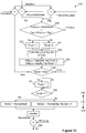
- Figure 13 is a flow diagram 1300 for time-domain residual echo suppression according to various embodiments of the present invention.
- the FirOutLev, ErrLev, and DesiredLev have been calculated in Section 2.2 as shown in Figure 9 .
- a determination 1396 of far end voice activity detection is performed and then an application 1398 of suppressing the residual echo is performed based on the determination.
- the determination of FEvad is based on one or more factors: 1) a ratio/comparison 1390 between the microphone signal (e.g., DesiredLev) and estimated echo level (e.g, FirOutLev); 2) the adaptation step size ⁇ in AEC Linear Processing (e.g., finding Max ⁇ in all frequency bins or bands 1392; comparision between Max ⁇ and predefined thresholds AdapSmall and AdapBig 1393); and 3) a ratio/comparison 1394 between the microphone signal (e.g., Desired Lev) and reduced echo level (e.g., ErrLev).
- a ratio/comparison 1390 between the microphone signal (e.g., DesiredLev) and estimated echo level (e.g, FirOutLev)
- the adaptation step size ⁇ in AEC Linear Processing e.g., finding
- a residual echo suppression output signal z(n) 1399 is generated (e.g., output of TD REC 418, 518).
- HPF output may correspond to the output of HPF 416, 516 or any other component (e.g., 412, 512) of system 400, 500. It should be appreciated by those skilled in the art that the constant values and processes noted are for exemplary purposes only and that other values and processes may be substituted for achieving residual echo suppression.
- the reference signal X(k), error signal E(k), adaptive filter weight W(k), and the coherence C(k) have been calculated in Section 2.1 as shown in Figure 8 .
- the coherence C(k) gets high enough, there is no NE voice.
- the FD REC will further reduce the residual echo based on the ratio between the residual echo level IE(k)1 and the level of the estimated echo
- the binary mask approach (either bin-by-bin scheme, or band-by-band scheme) is adopted for the reduction.
- this proposed scheme can be adopted by both AEC and electrical echo cancellation.
- this invention supports one or more microphones and one or more reference channels.
- the numbers of microphones and reference channels are user configurable.
- FIG. 14 illustrates a typical computer system that can be used in connection with one or more embodiments of the present invention.
- the computer system 1400 includes one or more processors 1402 (also referred to as central processing units, or CPUs) that are coupled to storage devices including primary storage 1406 (typically a random access memory, or RAM) and another primary storage 1404 (typically a read only memory, or ROM).
- primary storage 1404 acts to transfer data and instructions uni-directionally to the CPU and primary storage 1406 is used typically to transfer data and instructions in a bi-directional manner.
- Both of these primary storage devices may include any suitable computer-readable media, including a computer program product comprising a machine readable medium on which is provided program instructions according to one or more embodiments of the present invention.
- a mass storage device 1408 also is coupled bi-directionally to CPU 1402 and provides additional data storage capacity and may include any of the computer-readable media, including a computer program product comprising a machine readable medium on which is provided program instructions according to one or more embodiments of the present invention.
- the mass storage device 1408 may be used to store programs, data and the like and is typically a secondary storage medium such as a hard disk that is slower than primary storage. It will be appreciated that the information retained within the mass storage device 1408, may, in appropriate cases, be incorporated in standard fashion as part of primary storage 1406 as virtual memory.
- a specific mass storage device such as a CD-ROM may also pass data uni-directionally to the CPU.
- CPU 1402 also is coupled to an interface 1410 that includes one or more input/output devices such as such as video monitors, track balls, mice, keyboards, microphones, touch-sensitive displays, transducer card readers, magnetic or paper tape readers, tablets, styluses, voice or handwriting recognizers, or other well-known input devices such as, of course, other computers.
- CPU 1402 optionally may be coupled to a computer or telecommunications network using a network connection as shown generally at 1412. With such a network connection, it is contemplated that the CPU might receive information from the network, or might output information to the network in the course of performing the above-described method steps.
- the above-described devices and materials will be familiar to those of skill in the computer hardware and software arts.
Landscapes
- Engineering & Computer Science (AREA)
- Signal Processing (AREA)
- Computer Networks & Wireless Communication (AREA)
- Human Computer Interaction (AREA)
- Health & Medical Sciences (AREA)
- Audiology, Speech & Language Pathology (AREA)
- Quality & Reliability (AREA)
- Physics & Mathematics (AREA)
- Acoustics & Sound (AREA)
- Multimedia (AREA)
- Computational Linguistics (AREA)
- Cable Transmission Systems, Equalization Of Radio And Reduction Of Echo (AREA)
- Circuit For Audible Band Transducer (AREA)
- Telephone Function (AREA)
- Soundproofing, Sound Blocking, And Sound Damping (AREA)
Description
- The present invention relates to processing signals. More particularly, the present invention relates to a system and method for processing signals to reduce echo or noise.
- With the rapid development and converged uses of various customer electronic devices, hands-free communication systems, speakerphones, laptops with internal or external speakers, and videoconference systems involving the use of loudspeakers and microphones, a user is able to talk more naturally without using a handset. This type of use makes application environments more complex and harder to deal with. Moreover, this emerging application leads to new additional problems, e.g., the situation that the user's own voice can be heard over at the remote site with a delay but cannot be noticed at the local site. In addition, electrical echoes may occur from signal reflections in hybrid circuits that convert between 4-wire and 2-wire circuits. All the above suggests a need for the superposition of echo presented together with the target speech signal by different ways from existing echo cancellation systems.
- Accordingly, goals of this invention include addressing the above problems by providing an effective and robust echo cancellation system and its real-time implementation.
-
US7672445 discloses techniques for suppressing large echo due to non-linearity and unstable adaptive filters. - For various, time-varying and complex environments, this invention proposes an effective, simple and robust echo cancellation (EC) scheme with good audio quality and double talk performance. More importantly, the proposed scheme can automatically reconfigure in real-time the system settings, processing structures and parameters to deal with any practical application environment while continually maintaining good performance.
- According to one aspect of the invention, a system for processing signals includes an echo cancellation processing module, a nonlinear echo processing module, and an echo leakage prevention module. The echo cancellation linear processing module is operable to generate a first output signal by adaptively filtering an input signal. The echo cancellation linear processing module comprises an echo cancellation operator for generating a residual echo signal by subtracting an estimated echo signal from the input signal, and a first complex adaptive filter configured for generating a first estimated echo signal based on a first reference signal and the residual echo signal, wherein the estimated echo signal is the first estimated echo signal. The first output signal is the input signal with any linear echo reduced. The nonlinear echo processing module is operable to generate a second output signal based on the first output signal. The nonlinear echo processing module comprises a nonlinear echo determination module configured for determining whether nonlinear echo is present in the first output signal, a nonlinear echo gain module configured for assigning a nonlinear echo gain for reducing nonlinear echo based on whether nonlinear echo is present in the first output signal; and a nonlinear echo operator configured for applying the nonlinear echo gain to the first output signal in generating the second output signal. The second output signal is the first output signal with any residual linear echo or nonlinear echo reduced. The echo leakage prevention module is operable to generate a third output signal based on the second output signal. The echo leakage prevention module comprises an echo leakage determination module configured for determining whether a root mean square value of the input signal is below a minimum input threshold, an echo leakage gain module configured for assigning an echo leakage gain for reducing echo leakage based on whether the root mean square value of the input signal is below the minimum input threshold and an echo leakage operator configured for applying the echo leakage gain to the second output signal in generating the third output signal. The third output signal is the second output signal with echo leakage reduced.
- According to various embodiments, the system may include a first residual echo suppression module operable to generate a fourth output signal based on the third output signal with any additional residual echo reduced. The system may also include a second residual echo suppression module operable to generate a fifth output signal based on the fourth output signal with any additional residual echo reduced. In this case, the first residual echo suppression module is based in the time-domain and the second residual echo suppression module is based in the frequency-domain. Yet, the system may include a HPF operable to reduce low frequency residual echo or noise. The HPF is typically positioned inline with the input signal.
- According to another aspect of the invention, a method for an echo cancellation system to process signals is provided. The method includes: 1) generating a first output signal by adaptively filtering an input signal such that the first output signal is the input signal with any linear echo reduced, by generating a residual echo signal by subtracting an estimated echo signal from the input signal and generating a first estimated echo signal based on a first reference signal, the residual echo signal, and filter weights, wherein the estimated echo signal is the first estimated echo signal, and wherein the filter weights are updated automatically by coherence values based on the input signal and the first reference signal in real time; 2) generating a second output signal based on the first output signal such that the second output signal is the first output signal with any residual linear echo or nonlinear echo reduced by determining whether nonlinear echo is present in the first output signal, assigning a nonlinear echo gain for reducing nonlinear echo based on whether nonlinear echo is present in the first output signal, and applying the nonlinear echo gain to the first output signal in generating the second output signal; and 3) generating a third output signal based on the second output signal such that the third output signal is the second output signal with echo leakage reduced by determining whether a root mean square value of the input signal is below a minimum input threshold, assigning an echo leakage gain for reducing echo leakage based on whether the root mean square value of the input signal is below the minimum input threshold, and applying the echo leakage gain to the second output signal in generating the third output signal.
- With the proposed adaptive nonlinear echo suppression, the nonlinear echo caused by the nonlinearity, instable adaptive filter, and so on, can be effectively reduced. With the proposed nonlinear processors (NLPs), the residual echo can be greatly reduced so as to avoid the howling effect which is highly undesired. With the proposed echo leakage prevention, the system output will not result in echo caused by the linear EC unit when the microphone is taken off or muted in the acoustic echo cancellation (AEC) system.
- The designs of each unit are independent of the levels of the input audio signal and the EC reference signal. The proposed scheme can provide the users with good audio quality, good full-duplex performance, and an effective solution for any acoustic EC and electrical EC applications.
- The invention extends to a machine readable medium embodying a sequence of instructions that, when executed by a machine, cause the machine to carry out any of the methods described herein.
- These and other features and advantages of the present invention are described below with reference to the drawings.
-
-
Figure 1 is a schematic block diagram illustrating a conventional system for acoustic echo cancellation. -
Figure 2 is a schematic block diagram illustrating a system for acoustic echo cancellation according to various embodiments of the present invention. -
Figure 3 is a schematic block diagram illustrating a system for acoustic and electrical echo cancellations according to various embodiments of the present invention. -
Figure 4 is a schematic block diagram illustrating a system for acoustic echo cancellation according to various embodiments of the present invention. -
Figure 5 is a schematic block diagram illustrating a system for acoustic echo cancellation with integrated noise reduction according to various embodiments of the present invention. -
Figure 6 is a schematic block diagram illustrating a system/module for frequency-domain adaptive linear filtering according to various embodiments of the present invention. -
Figure 7 is a schematic block diagram illustrating a system/module for acoustic echo cancellation with two or more reference channels according to various embodiments of the present invention. -
Figure 8 is a schematic block diagram illustrating a system/module for frequency-domain adaptive linear filtering according to various embodiments of the present invention. -
Figure 9 is a flow diagram for nonlinear echo processing according to various embodiments of the present invention. -
Figure 10 is a flow diagram for echo leakage prevention according to various embodiments of the present invention. -
Figure 11 is a schematic block diagram illustrating a system for acoustic echo cancellation with integrated HPFs according to various embodiments of the present invention. -
Figure 12 is a diagram illustrating a frequency response of an HPF according to various embodiments of the present invention. -
Figure 13 is a flow diagram for time-domain residual echo suppression according to various embodiments of the present invention. -
Figure 14 illustrates a typical computer system that can be used in connection with one or more embodiments of the present invention. - Reference will now be made in detail to preferred embodiments of the invention. Examples of the preferred embodiments are illustrated in the accompanying drawings. While the invention will be described in conjunction with these preferred embodiments, it will be understood that it is not intended to limit the invention to such preferred embodiments. In the following description, numerous specific details are set forth in order to provide a thorough understanding of the present invention. The present invention may be practiced without some or all of these specific details. In other instances, well known mechanisms have not been described in detail in order not to unnecessarily obscure the present invention.
- It should be noted herein that throughout the various drawings like numerals and references refer to like parts. The various drawings illustrated and described herein are used to illustrate various features of the invention. To the extent that a particular feature is illustrated in one drawing and not another, except where otherwise indicated or where the structure inherently prohibits incorporation of the feature, it is to be understood that those features may be adapted to be included in the embodiments represented in the other figures, as if they were fully illustrated in those figures. Unless otherwise indicated, the drawings are not necessarily to scale. Any dimensions provided on the drawings are not intended to be limiting as to the scope of the invention but merely illustrative.
- Hands-free communication systems, speakerphones, laptops with internal or external speakers, and videoconference setting-ups involve the use of loudspeakers and microphones. They allow users to talk more naturally without using a handset. This new type of use leads to new problems, namely the superposition of acoustical echo presented together with the target speech signal. It results in the other site hearing his/her own voice with a delay, but will not be noticed at the local site.
- Electrical echo may also be caused by signal reflection in a hybrid circuit that converts between 4-wire and 2-wire circuits. Users in this situation will also hear their own voice with a delay which is very annoying.
-
Figure 1 is a schematic block diagram illustrating a conventional system for acoustic echo cancellation.Conventional system 100 includes a linear processing module 110 and anonlinear processing module 112 as shown inFigure 1 . ADelay 118 typically compensates for the pure delay resulting from a digital to analog (D/A) converter (not shown), the distance between themicrophone 103 and theloudspeaker 107, buffering scheme, and an analog to digital (A/D) converter (not shown). An adaptive linear filter 116 attempts to model the transfer function between theloudspeaker signal 108 and themicrophone signal 102. This transfer function accounts for the two transducers (e.g.,microphone 103, loudspeaker 107), the A/D and D/A converters, and theacoustic echo path 109. The adaptive linear filter 116 constantly monitors the transfer function and tracks changes in theacoustic echo path 109 with commonly employed least mean-squared (LMS) based algorithms. The adaptive linear filter 116 can be implemented in either time domain (TD) or frequency-domain (FD). Some of these techniques are disclosed in [1] Toon van Walterschoot, Geert Rombouts, Piet Verhoeve and Marc Moonen, "Double-Talk-Robust Prediction Error Identification Algorithms for Acoustic Echo Cancellation," IEEE Transactions on Signal Processing, Vol. 55, No. 3, pp.846-858, March 2007; and [2] Paul L. Feintuch, "Normalized Frequency Domain LMS Adaptive Filter,"U.S. Pat. No. 5, 4,939,685, issued on Jan. 3, 1990 output 122 of the adaptive linear filter 116 is very close to the echo portion of themicrophone signal 102. Subtracting the adaptivelinear filter output 122 from themicrophone signal 102 reduces the echo. Since there is always a residual echo after the linear adaptive subtraction due to the fact that the adaptive linear filter 116 can neither be 100% accurate nor exactly model the transfer function, thenonlinear processing module 112 implements a nonlinear processor (NLP) technique that is necessary to further reduce the residual echo. - However, traditional NLPs (e.g., center clipper as disclosed in [3] Campanella; Samuel Joseph, et al., "Echo suppressor using frequency-selective center clipping",
U.S. Pat. No. 4,031,338, issued on June 21, 1977 ; [4] Lassaux; Jean, et al., "Echo canceller and center clipper control arrangement",U.S. Pat. No. 4,679,230, issued on July 7, 1987 ; or [5]. Rasmusson; Jim A. J., "Echo-canceling system and method using echo estimate to modify error signal",U.S. Pat. No. 5,475,731, issued on December 12, 1995 ; noise-gate or spectral subtraction approaches) will distort the near-end voice. Also, it would not get rid of the residual echo very well due to the following factors: (1) user movement, position changes in the microphone(s) and loudspeaker(s), and loudspeaker volume changes resulting in a time-varying echo, especially when the echo path changes faster than the convergence rate of the adaptive filter; and (2) when the near-end talker is speaking, the adaptive filter will tend to erroneously "adjust" itself to what it perceives to be a change in theacoustic echo path 109. - In addition, the adaptive linear filter 116 would not be able to remove the nonlinear echo caused by any instability of the adaptive filter and non-linearity in the
AEC system 100 circuitry, such as from theloudspeaker 107, A/D converter, D/A converter due to an overdriven speaker, microphone saturation, mechanical vibration, and so on. Moreover, when themicrophone 103 is muted or taken away while a far-end user is still speaking, the linear adaptive filter 116 would not have exactly zero values for all the filter weights, which will result in the echo at the output and is a kind of echo leakage problem. Similarly, this condition occurs in the electrical EC system for the case of no electrical echo. - Obviously, techniques that suppress the nonlinear echo and residual echo together with prevent the echo leakage are highly desirable. It is a goal of this invention to address the above problems by providing an effective and robust echo cancellation system with improved echo cancellation performance and enhanced full-duplex communication.
- According to various embodiment of the present invention, a universal reconfigurable scheme and system are provided for reducing nonlinear echo and residual echo, and for echo leakage prevention in various time-varying and complex environments. According to one embodiment, an echo cancellation system includes (1) an adaptive linear filter implemented in either time-domain or frequency-domain; (2) a nonlinear echo suppression; (3) echo leakage prevention; (4) direct current (DC), low frequency residual echo and noise reduction; (5) time-domain nonlinear processor (NLP) to reduce the residual echo; and (6) frequency-domain NLP to further reduce the residual echo. The echo cancellation system is universally applicable to acoustic echo cancellation (AEC) and/or electrical echo cancellation applications. In terms of AEC, this invention is reconfigurable for one or more microphones and/or one or more reference channels. The numbers of microphones and reference channels are user configurable.
-
Figure 2 is a schematic block diagram illustrating asystem 200 for acoustic echo cancellation according to various embodiments of the present invention.Fig.2 shows an application setting ofAEC system 200.System 200 includes components such as aconverter 212,loudspeaker 207,microphone 203,converter 210,AEC processor 214, and wired or wireless network/circuitry interconnecting the various system components.Converter 212 is configured for receiving asignal 206 from a network coupled to a far-end (remote) site, convertingsignal 206 with converter 212 (e.g., D/A converter), and outputting a convertedsignal 208 ofsignal 206 toloudspeaker 207 for reproduction at a near-end (local) site. In a preferred embodiment, the reproduced convertedsignal 208 includes an acoustic echo alongacoustic echo path 209.Microphone 203 is configured for receiving the acoustic echo alongacoustic echo path 209 and outputting it as amicrophone signal 202 toconverter 210.Converter 210 is configured for receivingmicrophone signal 202, convertingmicrophone signal 202 with converter 210 (e.g., A/D converter), and outputting a converted signal ofmicrophone signal 202 toAEC processor 214.AEC processor 214 may include any portion of conventional linear processing module 110, conventionalnonlinear processing module 112, and any other improvements discussed herein (e.g., SeeFigures 4 and 5 for further details). In general,AEC processor 214 is configured for generating and outputting an acoustic echo-suppressedvoice signal 204 to the network coupled to the far-end (remote) site. Acoustic echo-suppressedvoice signal 204 is generated based on the convertedmicrophone signal 202 of the acoustic echo alongacoustic echo path 209 and an AEC reference signal (e.g., signal 206). -
Figure 3 is a schematic block diagram illustrating asystem 300 for acoustic and electrical echo cancellations according to various embodiments of the present invention.Fig. 3 shows the application setting of acoustic and electricalecho cancellations system 300.System 300 includes similar components asSystem 200 such as aconverter 212,loudspeaker 207,microphone 203,converter 210,AEC processor 214, and wired or wireless network/circuitry interconnecting the various system components.System 300 also includes a local/line/electrical echo cancellation (LEC)processor 316. Similar toAEC processor 214,LEC processor 316 may include any portion of conventional linear processing module 110, conventionalnonlinear processing module 112, and any other improvements discussed herein (e.g., SeeFigures 4 and 5 for further details). In general,LEC processor 316 is configured for generating and outputting a local echo-suppressed far-end voice signal 320 toconverter 212 and as the AEC reference toAEC processor 214. Local echo-suppressed far-end voice signal 320 is generated based on asignal 306 representative of the electrical echo alongelectrical echo path 305 and aLEC reference signal 318.LEC reference signal 318 is an acoustic echo-suppressedvoice signal 304 generated fromAEC Processor 214 to the network coupled to the far-end (remote) site. In a preferred embodiment, the proposed "nonlinear echo suppression" component applies for AEC while the rest of the components apply for both AEC and LEC. Therefore, the present invention relates more specifically to the techniques for AEC. -
Figure 4 is a schematic block diagram illustrating asystem 400 for acoustic echo cancellation according to various embodiments of the present invention. The proposedsystem 400 mainly includes six processing units: (1) AEC Linear Processing 410, i.e., an adaptive linear filter (See Sec. 2.1 andFigures 6, 7 , and8 for further details); (2) nonlinear echo suppression 412 (See Sec. 2.2 andFigure 9 for further details); (3) echo leakage prevention 414 (See Sec. 2.3 andFigure 10 for further details); (4) high pass filter (HPF) 416, i.e., low frequency residual echo and noise reduction (See Sec. 2.4 andFigures 11 and12 for further details); (5)TD REC 418, i.e., time-domain residual echo suppression (See Sec. 2.5 andFigure 13 for further details); and (6)FD REC 420 , i.e., frequency-domain residual echo suppression (See Sec. 2.6 for further details). However, it will be appreciated by those skilled in the art that any combination of the six processing units may be used depending on the specific application. That is, any of the six processing units may be included, omitted, or reordered depending on the application. -
Sin 402 andRin 406 are the inputs to theAEC system 400 whereasSout 404 andRout 408 are the outputs of theAEC system 400. In a two-way voice communication system, the send path is fromSin 402 toSout 404 and the receive path is fromRin 406 toRout 408.Sin 402 is the microphone signal (e.g., 202) which includes near-end (NE) voice, NE environment noise, and acoustic echo. Rin 406 (e.g., 206, 306) is the far-end (FE) voice, i.e., input of the receive path. Sout 404 (e.g., 204, 304) is the echo-suppressed signal sent to the network for FE people to listen to. Rout 408 (e.g., 208) goes to the NE loudspeaker (e.g., 207) for NE people to listen to. In a preferred embodiment,FD REC 420 is configured for "50% STFT", which means short-time Fourier transform (STFT) withinput 50% overlap. -
Figure 5 is a schematic block diagram illustrating asystem 500 for acoustic echo cancellation with integrated noise reduction according to various embodiments of the present invention.System 500 includes similar elements as those insystem 400. For example,elements elements AEC system 500 has been integrated with a noise reduction (NR) technology such asFD NR 522, which is a frequency-domain NR. Many FD NR technologies are available, which is beyond the scope of this invention.System system AEC Processor 214 and/orLEC 316 Processor, and modified accordingly to their specific application. It will be appreciated by those skilled in the art that any combination of the seven processing units insystem 500 may be used depending on the specific application. - AEC Linear Processing (e.g., 410, 510) includes an adaptive linear filter that can be implemented in either time-domain or frequency-domain.
Figure 6 is a schematic block diagram illustrating a system/module 600 for frequency-domain adaptive linear filtering according to various embodiments of the present invention. An example of the FD least mean-squared (LMS) based algorithms is shown as inFigure 6 . InFigure 6 ,STFT 610 andISTFT 622 denote short-time Fourier transform and inverse STFT, respectively.Delay 618 compensates for any pure delay resulting from one or more of the following factors: a D/A converter (e.g., 212), the distance between the microphone (e.g., 203) and the loudspeaker (e.g., 207), buffering scheme, and an A/D converter (e.g., 210). The frequency domain (FD) filtering, i.e.,Complex Adaptive Filter 616, is implemented by a complex multiply. The index n and k are for sample index and the frame index, respectively. The output of the FD filtering, Y(k) 613, is the estimated echo. -
STFT 610 receivesinput signal Sin 602 and generatesoutput signal 612.Sin 602 is shown as a time-domain d(n) andoutput signal 612 as frequency-domain D(k).Sin 602 may correspond to a microphone signal (e.g.,Sin STFT 620 receivesinput signal 619 as a time-domain x(n) reference data and generatesoutput signal 621 as a frequency-domain X(k) reference data. Input signal x(n) 619 is generated byDelay 618 based oninput Rin 606, which may correspond to a AEC/LEC reference signal (e.g., 406, 506, 206, 318, 320).Complex Adaptive Filter 616 generates Y(k) estimatedecho signal 613 based on X(k) reference data signal 621 and E(k)residual echo signal 611, which is determined by comparing D(k)microphone signal 612 and Y(k) estimatedecho signal 613 with operator 614 (e.g., adder, subtractor, etc.). E(k)residual echo signal 611 is then processed byISTFT 622 to generateoutput signal 624 as a time-domain e(n) residual echo signal. Time-domain e(n) residual echo signal may correspond tooutput signals Figures 4 and 5 respectively. - If there are two or more loudspeakers, the estimated echo of each reference channels should be summed before the subtraction operation by
operator 614.Figure 7 is a schematic block diagram illustrating a system/module 700 for acoustic echo cancellation with two or more reference channels according to various embodiments of the present invention.Fig. 7 shows the AEC system with the m reference channels. According to a preferred embodiment, Y(k) estimatedecho signal 713 is based on adding together estimated echo signals for m reference channels. For example, Y(k) estimatedecho signal 713 is the result of adding Y1(k) estimatedecho signal 715 and Ym(k) estimatedecho signal 717 based onprocess modules process modules Figure 6 (e.g., 606, 618, 619, 620, 621, 616, 613). Further,elements corresponding elements - Another example of the FD least mean-squared (LMS) based algorithms is shown as in
Figure 8. Figure 8 is a schematic block diagram illustrating a system/module 800 for frequency-domain adaptive linear filtering according to various embodiments of the present invention. InFigure 8 , the block of "75% STFT" 830 means STFT withinput 75% overlap, the block of "75% Overlap" 832 means that the output has 75% overlap, theFFT 834 is the Fast Fourier transform. The u(n) 811 is the time-domain echo-reduced output. In a preferred embodiment, u(n) 811 corresponds tooutput signals Figures 4 and 5 respectively The block ofFilter Weights Update 836 is based on the FD normalized LMS, which is described in detail as follows:
The set of filter weights W(k) are updated according to

- In addition, the adaptation step size µ is automatically adjusted by the coherence between D(k) and X(k). The higher is the coherence, the larger the adaptation step size µ is. When the coherence gets low enough, the adaptation is frozen. As such, the proposed scheme can automatically reconfigure in real-time the system settings, processing structures and parameters to deal with any practical application environment while continually maintaining good performance. The calculation of the coherence is as follows:

- For the AEC system with the m reference channels. each reference channel has its own Complex Adaptive Filter processing. The Y(k) in
Fig. 8 will be the summation of the outputs of all the Complex Adaptive Filters. - For the AEC system with the N microphones, the above calculation will be repeated for N times. Therefore, for the AEC system with m reference channels and N microphones, there will be (m× N) adaptive processing.
-
Figure 9 is a flow diagram 900 for nonlinear echo processing according to various embodiments of the present invention. For example, the process flow ofNonlinear Echo Processing Figures 4 or 5 is illustrated as shown inFigure 9 . The smoother inFigure 9 is implemented as follows:
ErrLev 940,DesiredLev 942, andFirOutLev 944; and α = 0.9375 for the smoother ofNonLinGainFinal 946. Furthermore, the constants FirOutOverDesLarge, ErrThreshold, NonLinGainSmall, and NonLinGainStep are 0.99, 0.02, 0.40, and 0.002, respectively. - In
Figure, 9 , an Abs() block processes the energy level of its input signal, which is the absolute value of the corresponding input signal (e.g., u(n) 950, microphone signal d(n), estimated echo signal y(n)) Adetermination 941 is made as to whether non-linear echo is present. The determination is based on the estimated echo signal (e.g., FirOutLev), microphone signal (e.g., DesiredLev, Temp), and echo-reduced signal u(n) 950 (e.g., Err_Abs). A gain (e.g., 943, 945) is then assigned based on thedetermination 941. The nonlinear echo reduced output v(n) 948 is then generated, which is based on applying theappropriate gain Figures 4 and 5 respectively whereas u(n) 950 corresponds tooutput signals Figures 4 and 5 respectively. It should be appreciated by those skilled in the art that the constant values and processes noted are for exemplary purposes only and that other values and processes may be substituted for achieving nonlinear echo suppression. -
Figure 10 is a flow diagram 1000 for echo leakage prevention according to various embodiments of the present invention. For example, the process flow ofEcho Leakage Prevention Figures 4 or 5 is illustrated as shown inFigure 10 . The root-mean-square (RMS) value of the microphone signal (e.g., D(k)) in the frequency range of 600 Hz to 2500 Hz is calculated 1061. Adetermination module 1062 is configured for determining whether the RMS value (e.g., RMSDes) of the microphone signal is less than a minimum input threshold (e.g., AEC_MIC_RMS_THRESHOLD). Again module Echo Leakage Prevention 414, 514). In a preferred embodiment, the AEC_MIC_RMS_THRESHOLD and AEC_noMic_Atten are 0.0005 and 0.25, respectively. It should be appreciated by those skilled in the art that the constant values and processes noted are for exemplary purposes only and that other values and processes may be substituted for achieving echo leakage prevention. -
Figure 11 is a schematic block diagram illustrating asystem 1100 for acoustic echo cancellation with integratedHPFs Figure 11 ; therefore, for the proposed AEC system with N microphones and m loudspeakers, there are (N + m) HPFs. According to a preferred embodiment of the present invention, only N HPFs are needed so that the MIPS and memory are reduced. HPFs can be integrated intosystems -
Figure 12 is a diagram 1200 illustrating a frequency response of an HPF according to various embodiments of the present invention. Specifically,Figure 12 is the frequency response of the designed HPF according to a preferred embodiment of the present invention. Thelower portion 1280 of diagram 1200 is the frequency response of the designed HPF for 0-8000 Hz. Theupper portion 1282 of diagram 1200 is an enlargement of thelower portion 1280 of diagram 1200 for the frequency response between 0-600 Hz. -
Figure 13 is a flow diagram 1300 for time-domain residual echo suppression according to various embodiments of the present invention. For example, the process flow ofTD REC Figures 4 or 5 is illustrated as shown inFigure 13 . The FirOutLev, ErrLev, and DesiredLev have been calculated in Section 2.2 as shown inFigure 9 . The constants inFigure 13 are as follows: ErrOverDes = 0.60, FirOutOverDesSmall = 0.878, FirOutOverDesLarge2 = 1.20, FirOutThresh = 0.01, AdapSmall = 0.002, AdapBig = 0.04, RecGainSmall = 0.1, and RecGainStep = 0.40. The Smoother is described by Eq. (4) with the factor α = 0.40. - In a preferred embodiment, a
determination 1396 of far end voice activity detection (FEvad) is performed and then anapplication 1398 of suppressing the residual echo is performed based on the determination. The determination of FEvad is based on one or more factors: 1) a ratio/comparison 1390 between the microphone signal (e.g., DesiredLev) and estimated echo level (e.g, FirOutLev); 2) the adaptation step size µ in AEC Linear Processing (e.g., finding Max µ in all frequency bins orbands 1392; comparision between Max µ and predefined thresholds AdapSmall and AdapBig 1393); and 3) a ratio/comparison 1394 between the microphone signal (e.g., Desired Lev) and reduced echo level (e.g., ErrLev). Based on the factors, a state assignment will be given (e.g., FEvad = 1; FEvad = 0) as in process blocks 1391 and 1393. The state assignments will then be used to determine whether far end voice activity is detected and thereby whether residual echo is present. For example, if FEvad = 1 in process block 1397, then residual echo is present. - Depending on whether far end voice activity is detected and thereby whether residual echo is present, an
application 1398 of suppressing the residual echo is performed. Accordingly, a residual echo suppression output signal z(n) 1399 is generated (e.g., output ofTD REC 418, 518). HPF output may correspond to the output ofHPF system - The reference signal X(k), error signal E(k), adaptive filter weight W(k), and the coherence C(k) have been calculated in Section 2.1 as shown in
Figure 8 . When the coherence C(k) gets high enough, there is no NE voice. In this case, the FD REC will further reduce the residual echo based on the ratio between the residual echo level IE(k)1 and the level of the estimated echo |W(k)X(k)|. - The binary mask approach (either bin-by-bin scheme, or band-by-band scheme) is adopted for the reduction. The binary mask is calculated as follows,

- In comparing with the prior-arts, some of the novelties and advantages of this proposed scheme can be summarized as follows:
- (1) An adaptive nonlinear echo suppression is proposed so as to remove the nonlinear echo caused by the non-linearity in the system circuitry;
- (2) A powerful nonlinear processing technique is proposed so as to get rid of the residual echo;
- (3) The highpass filters (HPFs) are traditionally applied for both the microphone signals and the AEC reference signals to reduce the low frequency noises. In this invention, the HPFs are only applied for microphone signals so as to save MIPS and memory and also reduce the residual echo and noise of low frequencies; and
- (4) A simple echo leakage prevention scheme is designed.
- The integration of one or more of the above system/process blocks has greatly reduced the residual echo so as to avoid the howling effect. With the proposed echo leakage prevention, the system output will not result in echo caused by the linear EC unit when the microphone is taken off or muted in the AEC system or when the electrical EC system has no electrical echo.
- This proposed scheme can be adopted by both AEC and electrical echo cancellation. In terms of AEC, this invention supports one or more microphones and one or more reference channels. The numbers of microphones and reference channels are user configurable.
- This invention also relates to using a computer system according to one or more embodiments of the present invention.
Figure 14 illustrates a typical computer system that can be used in connection with one or more embodiments of the present invention. Thecomputer system 1400 includes one or more processors 1402 (also referred to as central processing units, or CPUs) that are coupled to storage devices including primary storage 1406 (typically a random access memory, or RAM) and another primary storage 1404 (typically a read only memory, or ROM). As is well known in the art,primary storage 1404 acts to transfer data and instructions uni-directionally to the CPU andprimary storage 1406 is used typically to transfer data and instructions in a bi-directional manner. Both of these primary storage devices may include any suitable computer-readable media, including a computer program product comprising a machine readable medium on which is provided program instructions according to one or more embodiments of the present invention. - A
mass storage device 1408 also is coupled bi-directionally toCPU 1402 and provides additional data storage capacity and may include any of the computer-readable media, including a computer program product comprising a machine readable medium on which is provided program instructions according to one or more embodiments of the present invention. Themass storage device 1408 may be used to store programs, data and the like and is typically a secondary storage medium such as a hard disk that is slower than primary storage. It will be appreciated that the information retained within themass storage device 1408, may, in appropriate cases, be incorporated in standard fashion as part ofprimary storage 1406 as virtual memory. A specific mass storage device such as a CD-ROM may also pass data uni-directionally to the CPU. -
CPU 1402 also is coupled to aninterface 1410 that includes one or more input/output devices such as such as video monitors, track balls, mice, keyboards, microphones, touch-sensitive displays, transducer card readers, magnetic or paper tape readers, tablets, styluses, voice or handwriting recognizers, or other well-known input devices such as, of course, other computers. Finally,CPU 1402 optionally may be coupled to a computer or telecommunications network using a network connection as shown generally at 1412. With such a network connection, it is contemplated that the CPU might receive information from the network, or might output information to the network in the course of performing the above-described method steps. The above-described devices and materials will be familiar to those of skill in the computer hardware and software arts. - Although the foregoing invention has been described in some detail for purposes of clarity of understanding, it will be apparent that certain changes and modifications may be practiced within the scope of the appended claims. Accordingly, the present embodiments are to be considered as illustrative and not restrictive, and the invention is not to be limited to the details given herein, but may be modified within the scope of the appended claims.
Claims (9)
- A system for processing signals, comprising:an echo cancellation linear processing module (410,510) configured for generating a first output signal by adaptively filtering an input signal, the first output signal being the input signal with any linear echo reduced, the echo cancellation linear processing module comprising an echo cancellation operator for generating a residual echo signal by subtracting an estimated echo signal from the input signal, and a first complex adaptive filter configured for generating a first estimated echo signal based on a first reference signal and the residual echo signal, wherein the estimated echo signal is the first estimated echo signal;a nonlinear echo processing module (412,512) configured for generating a second output signal based on the first output signal, the second output signal being the first output signal with any residual linear echo or nonlinear echo reduced, the nonlinear echo processing module comprising a nonlinear echo determination module configured for determining whether nonlinear echo is present in the first output signal, a nonlinear echo gain module configured for assigning a nonlinear echo gain for reducing nonlinear echo based on whether nonlinear echo is present in the first output signal, and a nonlinear echo operator configured for applying the nonlinear echo gain to the first output signal in generating the second output signal; andan echo leakage prevention module (414, 514) configured for generating a third output signal based on the second output signal, the third output signal being the second output signal with echo leakage reduced, wherein the echo leakage prevention module comprises an echo leakage determination module configured for determining whether a root mean square value of the input signal is below a minimum input threshold, an echo leakage gain module configured for assigning an echo leakage gain for reducing echo leakage based on whether the root mean square value of the input signal is below the minimum input threshold, and an echo leakage operator configured for applying the echo leakage gain to the second output signal in generating the third output signal
- The system as recited in claim 1, wherein the echo cancellation linear processing module comprises:
a second complex adaptive filter configured for generating a second estimated echo signal based on a second reference signal and the residual echo signal, wherein the estimated echo signal is the first estimated echo signal plus the second estimated echo signal. - The system as recited in claim 1 or 2, wherein the complex adaptive filters use filter weights that are updated automatically by coherence values based on the input signal and the first reference signal in real time.
- The system as recited in any preceding claim, further comprising one or both of a first residual echo suppression module based in the time domain and a second residual echo suppression module based in the frequency domain, wherein the first and/or second residual echo suppression modules comprise:a residual echo determination module for determining whether residual echo is present by subtracting an estimated echo signal from the input signal;a residual echo gain module configured for assigning a residual echo gain for reducing residual echo based on whether a residual echo is present, the gain being based on a ratio between the residual echo and the level of the estimated echo; anda residual echo operator configured for applying the residual echo gain to the third output signal to generate a fourth output signal or to the fourth output signal to generate a fifth output signal.
- The system as recited in any preceding claim, further comprising:
a high pass filter configured for reducing low frequency residual echo or noise, the high pass filter being positioned inline with the input signal. - The system as recited in any preceding claim, wherein the input signal corresponds to a voice signal and the system is for processing signals to reduce acoustic echo, or to an electrical signal and the system is for processing signals to reduce electrical echo.
- A method for an echo cancellation system to process signals:generating a first output signal by adaptively filtering an input signal, the first output signal being the input signal with any linear echo reduced, by generating a residual echo signal by subtracting an estimated echo signal from the input signal and generating a first estimated echo signal based on a first reference signal, the residual echo signal, and filter weights, wherein the estimated echo signal is the first estimated echo signal, and wherein the filter weights are updated automatically by coherence values based on the input signal and the first reference signal in real time;generating a second output signal based on the first output signal, the second output signal being the first output signal with any residual linear echo or nonlinear echo reduced, by determining whether nonlinear echo is present in the first output signal, assigning a nonlinear echo gain for reducing nonlinear echo based on whether nonlinear echo is present in the first output signal, and applying the nonlinear echo gain to the first output signal in generating the second output signal; andgenerating a third output signal based on the second output signal, the third output signal being the second output signal with echo leakage reduced, by determining whether a root mean square value of the input signal is below a minimum input threshold, assigning an echo leakage gain for reducing echo leakage based on whether the root mean square value of the input signal is below the minimum input threshold, and applying the echo leakage gain to the second output signal in generating the third output signal.
- The method as recited in claim 7, further comprising:
applying residual echo suppression in one or both of the time domain and the frequency domain, wherein applying residual echo suppression comprises:determining whether residual echo is present;assigning a residual echo gain for reducing residual echo based on whether residual echo is present; andapplying the residual echo gain to the third output signal to generate a fourth output signal or to the fourth output signal to generate a fifth output signal. - A computer program product for processing signals to reduce either acoustic or electrical echo, the computer program product being embodied in a non-transitory computer readable medium and comprising computer executable instructions for implementing a method according to claim 7 or claim 8.
Applications Claiming Priority (2)
| Application Number | Priority Date | Filing Date | Title |
|---|---|---|---|
| US201261640681P | 2012-04-30 | 2012-04-30 | |
| PCT/US2013/038958 WO2013166080A1 (en) | 2012-04-30 | 2013-04-30 | A universal reconfigurable echo cancellation system |
Publications (3)
| Publication Number | Publication Date |
|---|---|
| EP2845189A1 EP2845189A1 (en) | 2015-03-11 |
| EP2845189A4 EP2845189A4 (en) | 2016-01-13 |
| EP2845189B1 true EP2845189B1 (en) | 2018-09-05 |
Family
ID=49514835
Family Applications (1)
| Application Number | Title | Priority Date | Filing Date |
|---|---|---|---|
| EP13784615.0A Active EP2845189B1 (en) | 2012-04-30 | 2013-04-30 | A universal reconfigurable echo cancellation system |
Country Status (5)
| Country | Link |
|---|---|
| US (1) | US9451078B2 (en) |
| EP (1) | EP2845189B1 (en) |
| CN (1) | CN104395957B (en) |
| SG (1) | SG11201407085UA (en) |
| WO (1) | WO2013166080A1 (en) |
Families Citing this family (73)
| Publication number | Priority date | Publication date | Assignee | Title |
|---|---|---|---|---|
| US9530428B2 (en) * | 2013-05-14 | 2016-12-27 | Mitsubishi Electric Corporation | Echo cancellation device |
| CN104754157B (en) * | 2013-12-26 | 2017-06-16 | 联芯科技有限公司 | A kind of device for suppressing residual echo and system |
| GB2527865B (en) * | 2014-10-30 | 2016-12-14 | Imagination Tech Ltd | Controlling operational characteristics of an acoustic echo canceller |
| CN107210777B (en) * | 2015-01-05 | 2019-09-13 | 美国莱迪思半导体公司 | Full-duplex transceiver, the method and computer readable storage medium for executing full-duplex communication |
| WO2016130459A1 (en) | 2015-02-09 | 2016-08-18 | Dolby Laboratories Licensing Corporation | Nearby talker obscuring, duplicate dialogue amelioration and automatic muting of acoustically proximate participants |
| US9565493B2 (en) | 2015-04-30 | 2017-02-07 | Shure Acquisition Holdings, Inc. | Array microphone system and method of assembling the same |
| US9554207B2 (en) | 2015-04-30 | 2017-01-24 | Shure Acquisition Holdings, Inc. | Offset cartridge microphones |
| JP6343585B2 (en) * | 2015-05-14 | 2018-06-13 | 日本電信電話株式会社 | Unknown transmission system estimation device, unknown transmission system estimation method, and program |
| CN104994249B (en) * | 2015-05-19 | 2017-03-15 | 百度在线网络技术(北京)有限公司 | Sound method for echo cancellation and device |
| KR101715198B1 (en) * | 2015-11-18 | 2017-03-10 | 광주과학기술원 | Speech Reinforcement Method Using Selective Power Budget |
| US10509626B2 (en) | 2016-02-22 | 2019-12-17 | Sonos, Inc | Handling of loss of pairing between networked devices |
| US10095470B2 (en) | 2016-02-22 | 2018-10-09 | Sonos, Inc. | Audio response playback |
| US10743101B2 (en) | 2016-02-22 | 2020-08-11 | Sonos, Inc. | Content mixing |
| US10264030B2 (en) | 2016-02-22 | 2019-04-16 | Sonos, Inc. | Networked microphone device control |
| US20170365255A1 (en) | 2016-06-15 | 2017-12-21 | Adam Kupryjanow | Far field automatic speech recognition pre-processing |
| US10134399B2 (en) | 2016-07-15 | 2018-11-20 | Sonos, Inc. | Contextualization of voice inputs |
| US10115400B2 (en) | 2016-08-05 | 2018-10-30 | Sonos, Inc. | Multiple voice services |
| US10129408B1 (en) * | 2016-10-11 | 2018-11-13 | Google Llc | Residual echo detection based on non-causality |
| US10181323B2 (en) | 2016-10-19 | 2019-01-15 | Sonos, Inc. | Arbitration-based voice recognition |
| US10264116B2 (en) | 2016-11-02 | 2019-04-16 | Nokia Technologies Oy | Virtual duplex operation |
| CN106782504B (en) * | 2016-12-29 | 2019-01-22 | 百度在线网络技术(北京)有限公司 | Audio recognition method and device |
| US9881632B1 (en) * | 2017-01-04 | 2018-01-30 | 2236008 Ontario Inc. | System and method for echo suppression for in-car communications |
| US10367948B2 (en) | 2017-01-13 | 2019-07-30 | Shure Acquisition Holdings, Inc. | Post-mixing acoustic echo cancellation systems and methods |
| KR102580418B1 (en) * | 2017-02-07 | 2023-09-20 | 삼성에스디에스 주식회사 | Acoustic echo cancelling apparatus and method |
| CN106601266A (en) * | 2017-02-24 | 2017-04-26 | 喜大(上海)网络科技有限公司 | Echo cancellation method, device and system |
| US10475449B2 (en) | 2017-08-07 | 2019-11-12 | Sonos, Inc. | Wake-word detection suppression |
| KR102478951B1 (en) * | 2017-09-04 | 2022-12-20 | 삼성전자주식회사 | Method and apparatus for removimg an echo signal |
| US10048930B1 (en) | 2017-09-08 | 2018-08-14 | Sonos, Inc. | Dynamic computation of system response volume |
| CN107610714A (en) * | 2017-09-13 | 2018-01-19 | 西南交通大学 | The echo cancel method of the minimum cube absolute value attracted based on a norm zero |
| US10446165B2 (en) * | 2017-09-27 | 2019-10-15 | Sonos, Inc. | Robust short-time fourier transform acoustic echo cancellation during audio playback |
| US10621981B2 (en) | 2017-09-28 | 2020-04-14 | Sonos, Inc. | Tone interference cancellation |
| US10482868B2 (en) | 2017-09-28 | 2019-11-19 | Sonos, Inc. | Multi-channel acoustic echo cancellation |
| US10466962B2 (en) | 2017-09-29 | 2019-11-05 | Sonos, Inc. | Media playback system with voice assistance |
| CN108055417B (en) * | 2017-12-26 | 2020-09-29 | 杭州叙简科技股份有限公司 | Audio processing system and method for inhibiting switching based on voice detection echo |
| US11175880B2 (en) | 2018-05-10 | 2021-11-16 | Sonos, Inc. | Systems and methods for voice-assisted media content selection |
| CN108831497B (en) * | 2018-05-22 | 2020-06-09 | 出门问问信息科技有限公司 | Echo compression method and device, storage medium and electronic equipment |
| US10959029B2 (en) | 2018-05-25 | 2021-03-23 | Sonos, Inc. | Determining and adapting to changes in microphone performance of playback devices |
| CN112335261B (en) | 2018-06-01 | 2023-07-18 | 舒尔获得控股公司 | Patterned microphone array |
| US11297423B2 (en) | 2018-06-15 | 2022-04-05 | Shure Acquisition Holdings, Inc. | Endfire linear array microphone |
| CN109040498B (en) * | 2018-08-12 | 2022-01-07 | 瑞声科技(南京)有限公司 | Method and system for improving echo cancellation effect |
| US11076035B2 (en) | 2018-08-28 | 2021-07-27 | Sonos, Inc. | Do not disturb feature for audio notifications |
| US10587430B1 (en) | 2018-09-14 | 2020-03-10 | Sonos, Inc. | Networked devices, systems, and methods for associating playback devices based on sound codes |
| CN112889296A (en) | 2018-09-20 | 2021-06-01 | 舒尔获得控股公司 | Adjustable lobe shape for array microphone |
| US11024331B2 (en) | 2018-09-21 | 2021-06-01 | Sonos, Inc. | Voice detection optimization using sound metadata |
| US11100923B2 (en) | 2018-09-28 | 2021-08-24 | Sonos, Inc. | Systems and methods for selective wake word detection using neural network models |
| US11899519B2 (en) | 2018-10-23 | 2024-02-13 | Sonos, Inc. | Multiple stage network microphone device with reduced power consumption and processing load |
| US11183183B2 (en) | 2018-12-07 | 2021-11-23 | Sonos, Inc. | Systems and methods of operating media playback systems having multiple voice assistant services |
| US11132989B2 (en) | 2018-12-13 | 2021-09-28 | Sonos, Inc. | Networked microphone devices, systems, and methods of localized arbitration |
| US10867604B2 (en) | 2019-02-08 | 2020-12-15 | Sonos, Inc. | Devices, systems, and methods for distributed voice processing |
| EP3942842A1 (en) | 2019-03-21 | 2022-01-26 | Shure Acquisition Holdings, Inc. | Housings and associated design features for ceiling array microphones |
| US11558693B2 (en) | 2019-03-21 | 2023-01-17 | Shure Acquisition Holdings, Inc. | Auto focus, auto focus within regions, and auto placement of beamformed microphone lobes with inhibition and voice activity detection functionality |
| WO2020191380A1 (en) | 2019-03-21 | 2020-09-24 | Shure Acquisition Holdings,Inc. | Auto focus, auto focus within regions, and auto placement of beamformed microphone lobes with inhibition functionality |
| US11120794B2 (en) | 2019-05-03 | 2021-09-14 | Sonos, Inc. | Voice assistant persistence across multiple network microphone devices |
| WO2020237206A1 (en) | 2019-05-23 | 2020-11-26 | Shure Acquisition Holdings, Inc. | Steerable speaker array, system, and method for the same |
| EP3977449A1 (en) | 2019-05-31 | 2022-04-06 | Shure Acquisition Holdings, Inc. | Low latency automixer integrated with voice and noise activity detection |
| US11200894B2 (en) | 2019-06-12 | 2021-12-14 | Sonos, Inc. | Network microphone device with command keyword eventing |
| US10871943B1 (en) | 2019-07-31 | 2020-12-22 | Sonos, Inc. | Noise classification for event detection |
| US11297426B2 (en) | 2019-08-23 | 2022-04-05 | Shure Acquisition Holdings, Inc. | One-dimensional array microphone with improved directivity |
| US11189286B2 (en) | 2019-10-22 | 2021-11-30 | Sonos, Inc. | VAS toggle based on device orientation |
| CN110931032B (en) * | 2019-11-19 | 2022-08-02 | 西安合谱声学科技有限公司 | Dynamic echo cancellation method and device |
| KR20210063931A (en) * | 2019-11-25 | 2021-06-02 | 삼성전자주식회사 | The electronic device performing wireless communication and the method for wireless communication |
| US11200900B2 (en) | 2019-12-20 | 2021-12-14 | Sonos, Inc. | Offline voice control |
| CN111091846B (en) * | 2019-12-26 | 2022-07-26 | 江亨湖 | Noise reduction method and echo cancellation system applying same |
| US11562740B2 (en) | 2020-01-07 | 2023-01-24 | Sonos, Inc. | Voice verification for media playback |
| US11308958B2 (en) | 2020-02-07 | 2022-04-19 | Sonos, Inc. | Localized wakeword verification |
| US11552611B2 (en) | 2020-02-07 | 2023-01-10 | Shure Acquisition Holdings, Inc. | System and method for automatic adjustment of reference gain |
| USD944776S1 (en) | 2020-05-05 | 2022-03-01 | Shure Acquisition Holdings, Inc. | Audio device |
| US11482224B2 (en) | 2020-05-20 | 2022-10-25 | Sonos, Inc. | Command keywords with input detection windowing |
| WO2021243368A2 (en) | 2020-05-29 | 2021-12-02 | Shure Acquisition Holdings, Inc. | Transducer steering and configuration systems and methods using a local positioning system |
| CN111696569B (en) * | 2020-06-29 | 2023-12-15 | 美的集团武汉制冷设备有限公司 | Echo cancellation method for home appliance, terminal and storage medium |
| US11984123B2 (en) | 2020-11-12 | 2024-05-14 | Sonos, Inc. | Network device interaction by range |
| US11785380B2 (en) | 2021-01-28 | 2023-10-10 | Shure Acquisition Holdings, Inc. | Hybrid audio beamforming system |
| US11875810B1 (en) | 2021-09-29 | 2024-01-16 | Amazon Technologies, Inc. | Echo cancellation using neural networks for environments with unsynchronized devices for audio capture and rendering |
Citations (1)
| Publication number | Priority date | Publication date | Assignee | Title |
|---|---|---|---|---|
| US5937060A (en) * | 1996-02-09 | 1999-08-10 | Texas Instruments Incorporated | Residual echo suppression |
Family Cites Families (9)
| Publication number | Priority date | Publication date | Assignee | Title |
|---|---|---|---|---|
| JP2853455B2 (en) * | 1992-05-15 | 1999-02-03 | ケイディディ株式会社 | Echo canceller |
| US7035396B1 (en) * | 1999-01-22 | 2006-04-25 | Agere Systems Inc. | Configurable echo canceller |
| US7672445B1 (en) * | 2002-11-15 | 2010-03-02 | Fortemedia, Inc. | Method and system for nonlinear echo suppression |
| CN101689371B (en) * | 2007-06-21 | 2013-02-06 | 皇家飞利浦电子股份有限公司 | A device for and a method of processing audio signals |
| US20090003586A1 (en) * | 2007-06-28 | 2009-01-01 | Fortemedia, Inc. | Signal processor and method for canceling echo in a communication device |
| JP4410819B2 (en) * | 2007-10-23 | 2010-02-03 | Okiセミコンダクタ株式会社 | Echo canceller |
| GB2457986A (en) * | 2008-03-06 | 2009-09-09 | Cambridge Silicon Radio Ltd | Acoustic echo cancellation |
| US8320553B2 (en) * | 2008-10-27 | 2012-11-27 | Apple Inc. | Enhanced echo cancellation |
| US8625775B2 (en) * | 2009-08-06 | 2014-01-07 | Hti Ip, L.L.C. | Method and system for reducing echo and noise in a vehicle passenger compartment environment |
-
2013
- 2013-04-30 US US14/398,102 patent/US9451078B2/en active Active
- 2013-04-30 SG SG11201407085UA patent/SG11201407085UA/en unknown
- 2013-04-30 CN CN201380034895.4A patent/CN104395957B/en active Active
- 2013-04-30 WO PCT/US2013/038958 patent/WO2013166080A1/en active Application Filing
- 2013-04-30 EP EP13784615.0A patent/EP2845189B1/en active Active
Patent Citations (1)
| Publication number | Priority date | Publication date | Assignee | Title |
|---|---|---|---|---|
| US5937060A (en) * | 1996-02-09 | 1999-08-10 | Texas Instruments Incorporated | Residual echo suppression |
Also Published As
| Publication number | Publication date |
|---|---|
| EP2845189A1 (en) | 2015-03-11 |
| SG11201407085UA (en) | 2014-12-30 |
| WO2013166080A1 (en) | 2013-11-07 |
| CN104395957A (en) | 2015-03-04 |
| CN104395957B (en) | 2018-02-13 |
| EP2845189A4 (en) | 2016-01-13 |
| US9451078B2 (en) | 2016-09-20 |
| US20150126255A1 (en) | 2015-05-07 |
Similar Documents
| Publication | Publication Date | Title |
|---|---|---|
| EP2845189B1 (en) | A universal reconfigurable echo cancellation system | |
| US11297178B2 (en) | Method, apparatus, and computer-readable media utilizing residual echo estimate information to derive secondary echo reduction parameters | |
| CN108376548B (en) | Echo cancellation method and system based on microphone array | |
| US6968064B1 (en) | Adaptive thresholds in acoustic echo canceller for use during double talk | |
| JP4955228B2 (en) | Multi-channel echo cancellation using round robin regularization | |
| US10269369B2 (en) | System and method of noise reduction for a mobile device | |
| US20130129100A1 (en) | Processing audio signals | |
| EP3295681A1 (en) | Acoustic echo cancelling system and method | |
| US10117021B1 (en) | Audio feedback reduction utilizing adaptive filters and nonlinear processing | |
| US9699554B1 (en) | Adaptive signal equalization | |
| US9947337B1 (en) | Echo cancellation system and method with reduced residual echo | |
| JP2004537219A (en) | Echo canceller with nonlinear echo suppressor for harmonic calculation | |
| KR101182017B1 (en) | Method and Apparatus for removing noise from signals inputted to a plurality of microphones in a portable terminal | |
| CN110956975A (en) | Echo cancellation method and device | |
| JP3507020B2 (en) | Echo suppression method, echo suppression device, and echo suppression program storage medium | |
| US9491306B2 (en) | Signal processing control in an audio device | |
| CN109215672B (en) | Method, device and equipment for processing sound information | |
| WO2019239977A1 (en) | Echo suppression device, echo suppression method, and echo suppression program | |
| Yang | Multilayer adaptation based complex echo cancellation and voice enhancement | |
| US6694020B1 (en) | Frequency domain stereophonic acoustic echo canceller utilizing non-linear transformations | |
| JP4413205B2 (en) | Echo suppression method, apparatus, echo suppression program, recording medium | |
| US10938992B1 (en) | Advanced audio feedback reduction utilizing adaptive filters and nonlinear processing | |
| Wallin et al. | Perceptual quality of hybrid echo canceler/suppressor | |
| Huang et al. | A study of the MVDR filter for acoustic echo suppression | |
| JP3403655B2 (en) | Method and apparatus for identifying unknown system using subband adaptive filter |
Legal Events
| Date | Code | Title | Description |
|---|---|---|---|
| PUAI | Public reference made under article 153(3) epc to a published international application that has entered the european phase |
Free format text: ORIGINAL CODE: 0009012 |
|
| 17P | Request for examination filed |
Effective date: 20141125 |
|
| AK | Designated contracting states |
Kind code of ref document: A1 Designated state(s): AL AT BE BG CH CY CZ DE DK EE ES FI FR GB GR HR HU IE IS IT LI LT LU LV MC MK MT NL NO PL PT RO RS SE SI SK SM TR |
|
| AX | Request for extension of the european patent |
Extension state: BA ME |
|
| DAX | Request for extension of the european patent (deleted) | ||
| REG | Reference to a national code |
Ref country code: DE Ref legal event code: R079 Ref document number: 602013043216 Country of ref document: DE Free format text: PREVIOUS MAIN CLASS: G10L0021020000 Ipc: G10L0021020800 |
|
| RA4 | Supplementary search report drawn up and despatched (corrected) |
Effective date: 20151215 |
|
| RIC1 | Information provided on ipc code assigned before grant |
Ipc: H04M 9/08 20060101ALI20151209BHEP Ipc: G10L 21/0208 20130101AFI20151209BHEP |
|
| STAA | Information on the status of an ep patent application or granted ep patent |
Free format text: STATUS: EXAMINATION IS IN PROGRESS |
|
| 17Q | First examination report despatched |
Effective date: 20161202 |
|
| GRAP | Despatch of communication of intention to grant a patent |
Free format text: ORIGINAL CODE: EPIDOSNIGR1 |
|
| STAA | Information on the status of an ep patent application or granted ep patent |
Free format text: STATUS: GRANT OF PATENT IS INTENDED |
|
| INTG | Intention to grant announced |
Effective date: 20180326 |
|
| GRAS | Grant fee paid |
Free format text: ORIGINAL CODE: EPIDOSNIGR3 |
|
| GRAA | (expected) grant |
Free format text: ORIGINAL CODE: 0009210 |
|
| STAA | Information on the status of an ep patent application or granted ep patent |
Free format text: STATUS: THE PATENT HAS BEEN GRANTED |
|
| AK | Designated contracting states |
Kind code of ref document: B1 Designated state(s): AL AT BE BG CH CY CZ DE DK EE ES FI FR GB GR HR HU IE IS IT LI LT LU LV MC MK MT NL NO PL PT RO RS SE SI SK SM TR |
|
| REG | Reference to a national code |
Ref country code: GB Ref legal event code: FG4D |
|
| REG | Reference to a national code |
Ref country code: CH Ref legal event code: EP |
|
| REG | Reference to a national code |
Ref country code: AT Ref legal event code: REF Ref document number: 1038781 Country of ref document: AT Kind code of ref document: T Effective date: 20180915 |
|
| REG | Reference to a national code |
Ref country code: IE Ref legal event code: FG4D |
|
| REG | Reference to a national code |
Ref country code: DE Ref legal event code: R096 Ref document number: 602013043216 Country of ref document: DE |
|
| REG | Reference to a national code |
Ref country code: NL Ref legal event code: FP |
|
| REG | Reference to a national code |
Ref country code: LT Ref legal event code: MG4D |
|
| PG25 | Lapsed in a contracting state [announced via postgrant information from national office to epo] |
Ref country code: BG Free format text: LAPSE BECAUSE OF FAILURE TO SUBMIT A TRANSLATION OF THE DESCRIPTION OR TO PAY THE FEE WITHIN THE PRESCRIBED TIME-LIMIT Effective date: 20181205 Ref country code: LT Free format text: LAPSE BECAUSE OF FAILURE TO SUBMIT A TRANSLATION OF THE DESCRIPTION OR TO PAY THE FEE WITHIN THE PRESCRIBED TIME-LIMIT Effective date: 20180905 Ref country code: NO Free format text: LAPSE BECAUSE OF FAILURE TO SUBMIT A TRANSLATION OF THE DESCRIPTION OR TO PAY THE FEE WITHIN THE PRESCRIBED TIME-LIMIT Effective date: 20181205 Ref country code: RS Free format text: LAPSE BECAUSE OF FAILURE TO SUBMIT A TRANSLATION OF THE DESCRIPTION OR TO PAY THE FEE WITHIN THE PRESCRIBED TIME-LIMIT Effective date: 20180905 Ref country code: GR Free format text: LAPSE BECAUSE OF FAILURE TO SUBMIT A TRANSLATION OF THE DESCRIPTION OR TO PAY THE FEE WITHIN THE PRESCRIBED TIME-LIMIT Effective date: 20181206 Ref country code: FI Free format text: LAPSE BECAUSE OF FAILURE TO SUBMIT A TRANSLATION OF THE DESCRIPTION OR TO PAY THE FEE WITHIN THE PRESCRIBED TIME-LIMIT Effective date: 20180905 Ref country code: SE Free format text: LAPSE BECAUSE OF FAILURE TO SUBMIT A TRANSLATION OF THE DESCRIPTION OR TO PAY THE FEE WITHIN THE PRESCRIBED TIME-LIMIT Effective date: 20180905 |
|
| REG | Reference to a national code |
Ref country code: AT Ref legal event code: MK05 Ref document number: 1038781 Country of ref document: AT Kind code of ref document: T Effective date: 20180905 |
|
| PG25 | Lapsed in a contracting state [announced via postgrant information from national office to epo] |
Ref country code: LV Free format text: LAPSE BECAUSE OF FAILURE TO SUBMIT A TRANSLATION OF THE DESCRIPTION OR TO PAY THE FEE WITHIN THE PRESCRIBED TIME-LIMIT Effective date: 20180905 Ref country code: AL Free format text: LAPSE BECAUSE OF FAILURE TO SUBMIT A TRANSLATION OF THE DESCRIPTION OR TO PAY THE FEE WITHIN THE PRESCRIBED TIME-LIMIT Effective date: 20180905 Ref country code: HR Free format text: LAPSE BECAUSE OF FAILURE TO SUBMIT A TRANSLATION OF THE DESCRIPTION OR TO PAY THE FEE WITHIN THE PRESCRIBED TIME-LIMIT Effective date: 20180905 |
|
| PG25 | Lapsed in a contracting state [announced via postgrant information from national office to epo] |
Ref country code: IT Free format text: LAPSE BECAUSE OF FAILURE TO SUBMIT A TRANSLATION OF THE DESCRIPTION OR TO PAY THE FEE WITHIN THE PRESCRIBED TIME-LIMIT Effective date: 20180905 Ref country code: EE Free format text: LAPSE BECAUSE OF FAILURE TO SUBMIT A TRANSLATION OF THE DESCRIPTION OR TO PAY THE FEE WITHIN THE PRESCRIBED TIME-LIMIT Effective date: 20180905 Ref country code: CZ Free format text: LAPSE BECAUSE OF FAILURE TO SUBMIT A TRANSLATION OF THE DESCRIPTION OR TO PAY THE FEE WITHIN THE PRESCRIBED TIME-LIMIT Effective date: 20180905 Ref country code: RO Free format text: LAPSE BECAUSE OF FAILURE TO SUBMIT A TRANSLATION OF THE DESCRIPTION OR TO PAY THE FEE WITHIN THE PRESCRIBED TIME-LIMIT Effective date: 20180905 Ref country code: IS Free format text: LAPSE BECAUSE OF FAILURE TO SUBMIT A TRANSLATION OF THE DESCRIPTION OR TO PAY THE FEE WITHIN THE PRESCRIBED TIME-LIMIT Effective date: 20190105 Ref country code: ES Free format text: LAPSE BECAUSE OF FAILURE TO SUBMIT A TRANSLATION OF THE DESCRIPTION OR TO PAY THE FEE WITHIN THE PRESCRIBED TIME-LIMIT Effective date: 20180905 Ref country code: AT Free format text: LAPSE BECAUSE OF FAILURE TO SUBMIT A TRANSLATION OF THE DESCRIPTION OR TO PAY THE FEE WITHIN THE PRESCRIBED TIME-LIMIT Effective date: 20180905 Ref country code: PL Free format text: LAPSE BECAUSE OF FAILURE TO SUBMIT A TRANSLATION OF THE DESCRIPTION OR TO PAY THE FEE WITHIN THE PRESCRIBED TIME-LIMIT Effective date: 20180905 |
|
| PG25 | Lapsed in a contracting state [announced via postgrant information from national office to epo] |
Ref country code: SK Free format text: LAPSE BECAUSE OF FAILURE TO SUBMIT A TRANSLATION OF THE DESCRIPTION OR TO PAY THE FEE WITHIN THE PRESCRIBED TIME-LIMIT Effective date: 20180905 Ref country code: PT Free format text: LAPSE BECAUSE OF FAILURE TO SUBMIT A TRANSLATION OF THE DESCRIPTION OR TO PAY THE FEE WITHIN THE PRESCRIBED TIME-LIMIT Effective date: 20190105 Ref country code: SM Free format text: LAPSE BECAUSE OF FAILURE TO SUBMIT A TRANSLATION OF THE DESCRIPTION OR TO PAY THE FEE WITHIN THE PRESCRIBED TIME-LIMIT Effective date: 20180905 |
|
| REG | Reference to a national code |
Ref country code: DE Ref legal event code: R097 Ref document number: 602013043216 Country of ref document: DE |
|
| PLBE | No opposition filed within time limit |
Free format text: ORIGINAL CODE: 0009261 |
|
| STAA | Information on the status of an ep patent application or granted ep patent |
Free format text: STATUS: NO OPPOSITION FILED WITHIN TIME LIMIT |
|
| PG25 | Lapsed in a contracting state [announced via postgrant information from national office to epo] |
Ref country code: DK Free format text: LAPSE BECAUSE OF FAILURE TO SUBMIT A TRANSLATION OF THE DESCRIPTION OR TO PAY THE FEE WITHIN THE PRESCRIBED TIME-LIMIT Effective date: 20180905 |
|
| 26N | No opposition filed |
Effective date: 20190606 |
|
| PG25 | Lapsed in a contracting state [announced via postgrant information from national office to epo] |
Ref country code: SI Free format text: LAPSE BECAUSE OF FAILURE TO SUBMIT A TRANSLATION OF THE DESCRIPTION OR TO PAY THE FEE WITHIN THE PRESCRIBED TIME-LIMIT Effective date: 20180905 |
|
| REG | Reference to a national code |
Ref country code: CH Ref legal event code: PL |
|
| REG | Reference to a national code |
Ref country code: BE Ref legal event code: MM Effective date: 20190430 |
|
| PG25 | Lapsed in a contracting state [announced via postgrant information from national office to epo] |
Ref country code: MC Free format text: LAPSE BECAUSE OF FAILURE TO SUBMIT A TRANSLATION OF THE DESCRIPTION OR TO PAY THE FEE WITHIN THE PRESCRIBED TIME-LIMIT Effective date: 20180905 Ref country code: LU Free format text: LAPSE BECAUSE OF NON-PAYMENT OF DUE FEES Effective date: 20190430 |
|
| PG25 | Lapsed in a contracting state [announced via postgrant information from national office to epo] |
Ref country code: CH Free format text: LAPSE BECAUSE OF NON-PAYMENT OF DUE FEES Effective date: 20190430 Ref country code: LI Free format text: LAPSE BECAUSE OF NON-PAYMENT OF DUE FEES Effective date: 20190430 |
|
| PG25 | Lapsed in a contracting state [announced via postgrant information from national office to epo] |
Ref country code: BE Free format text: LAPSE BECAUSE OF NON-PAYMENT OF DUE FEES Effective date: 20190430 |
|
| PG25 | Lapsed in a contracting state [announced via postgrant information from national office to epo] |
Ref country code: TR Free format text: LAPSE BECAUSE OF FAILURE TO SUBMIT A TRANSLATION OF THE DESCRIPTION OR TO PAY THE FEE WITHIN THE PRESCRIBED TIME-LIMIT Effective date: 20180905 |
|
| PG25 | Lapsed in a contracting state [announced via postgrant information from national office to epo] |
Ref country code: IE Free format text: LAPSE BECAUSE OF NON-PAYMENT OF DUE FEES Effective date: 20190430 |
|
| PG25 | Lapsed in a contracting state [announced via postgrant information from national office to epo] |
Ref country code: CY Free format text: LAPSE BECAUSE OF FAILURE TO SUBMIT A TRANSLATION OF THE DESCRIPTION OR TO PAY THE FEE WITHIN THE PRESCRIBED TIME-LIMIT Effective date: 20180905 |
|
| PG25 | Lapsed in a contracting state [announced via postgrant information from national office to epo] |
Ref country code: MT Free format text: LAPSE BECAUSE OF FAILURE TO SUBMIT A TRANSLATION OF THE DESCRIPTION OR TO PAY THE FEE WITHIN THE PRESCRIBED TIME-LIMIT Effective date: 20180905 Ref country code: HU Free format text: LAPSE BECAUSE OF FAILURE TO SUBMIT A TRANSLATION OF THE DESCRIPTION OR TO PAY THE FEE WITHIN THE PRESCRIBED TIME-LIMIT; INVALID AB INITIO Effective date: 20130430 |
|
| PG25 | Lapsed in a contracting state [announced via postgrant information from national office to epo] |
Ref country code: MK Free format text: LAPSE BECAUSE OF FAILURE TO SUBMIT A TRANSLATION OF THE DESCRIPTION OR TO PAY THE FEE WITHIN THE PRESCRIBED TIME-LIMIT Effective date: 20180905 |
|
| P01 | Opt-out of the competence of the unified patent court (upc) registered |
Effective date: 20230520 |
|
| PGFP | Annual fee paid to national office [announced via postgrant information from national office to epo] |
Ref country code: FR Payment date: 20230425 Year of fee payment: 11 Ref country code: DE Payment date: 20230427 Year of fee payment: 11 |
|
| PGFP | Annual fee paid to national office [announced via postgrant information from national office to epo] |
Ref country code: GB Payment date: 20230427 Year of fee payment: 11 |
|
| PGFP | Annual fee paid to national office [announced via postgrant information from national office to epo] |
Ref country code: NL Payment date: 20240426 Year of fee payment: 12 |