EP2843788A2 - Method for operating a power plant system - Google Patents
Method for operating a power plant system Download PDFInfo
- Publication number
- EP2843788A2 EP2843788A2 EP14169314.3A EP14169314A EP2843788A2 EP 2843788 A2 EP2843788 A2 EP 2843788A2 EP 14169314 A EP14169314 A EP 14169314A EP 2843788 A2 EP2843788 A2 EP 2843788A2
- Authority
- EP
- European Patent Office
- Prior art keywords
- power
- micro
- chp
- time
- control device
- Prior art date
- Legal status (The legal status is an assumption and is not a legal conclusion. Google has not performed a legal analysis and makes no representation as to the accuracy of the status listed.)
- Withdrawn
Links
Images


Classifications
-
- H—ELECTRICITY
- H02—GENERATION; CONVERSION OR DISTRIBUTION OF ELECTRIC POWER
- H02J—CIRCUIT ARRANGEMENTS OR SYSTEMS FOR SUPPLYING OR DISTRIBUTING ELECTRIC POWER; SYSTEMS FOR STORING ELECTRIC ENERGY
- H02J3/00—Circuit arrangements for ac mains or ac distribution networks
- H02J3/24—Arrangements for preventing or reducing oscillations of power in networks
-
- F—MECHANICAL ENGINEERING; LIGHTING; HEATING; WEAPONS; BLASTING
- F01—MACHINES OR ENGINES IN GENERAL; ENGINE PLANTS IN GENERAL; STEAM ENGINES
- F01K—STEAM ENGINE PLANTS; STEAM ACCUMULATORS; ENGINE PLANTS NOT OTHERWISE PROVIDED FOR; ENGINES USING SPECIAL WORKING FLUIDS OR CYCLES
- F01K13/00—General layout or general methods of operation of complete plants
- F01K13/02—Controlling, e.g. stopping or starting
-
- H—ELECTRICITY
- H02—GENERATION; CONVERSION OR DISTRIBUTION OF ELECTRIC POWER
- H02J—CIRCUIT ARRANGEMENTS OR SYSTEMS FOR SUPPLYING OR DISTRIBUTING ELECTRIC POWER; SYSTEMS FOR STORING ELECTRIC ENERGY
- H02J3/00—Circuit arrangements for ac mains or ac distribution networks
- H02J3/38—Arrangements for parallely feeding a single network by two or more generators, converters or transformers
- H02J3/381—Dispersed generators
-
- H—ELECTRICITY
- H02—GENERATION; CONVERSION OR DISTRIBUTION OF ELECTRIC POWER
- H02J—CIRCUIT ARRANGEMENTS OR SYSTEMS FOR SUPPLYING OR DISTRIBUTING ELECTRIC POWER; SYSTEMS FOR STORING ELECTRIC ENERGY
- H02J3/00—Circuit arrangements for ac mains or ac distribution networks
- H02J3/38—Arrangements for parallely feeding a single network by two or more generators, converters or transformers
- H02J3/46—Controlling of the sharing of output between the generators, converters, or transformers
-
- H—ELECTRICITY
- H02—GENERATION; CONVERSION OR DISTRIBUTION OF ELECTRIC POWER
- H02J—CIRCUIT ARRANGEMENTS OR SYSTEMS FOR SUPPLYING OR DISTRIBUTING ELECTRIC POWER; SYSTEMS FOR STORING ELECTRIC ENERGY
- H02J2310/00—The network for supplying or distributing electric power characterised by its spatial reach or by the load
- H02J2310/10—The network having a local or delimited stationary reach
- H02J2310/12—The local stationary network supplying a household or a building
Definitions
- the invention relates to a method for operating a power plant system comprising a plurality of distributed micro-CHP plants and at least one connected to the distributed micro-CHP plants connected via at least one communication network central control device. Moreover, the invention relates to a power plant system and a computer program.
- micro-cogeneration plants such as micro-cogeneration plants (micro-CHP systems) are increasingly being used to supply particular individual buildings, such as single-family, two-family, multi-family and office buildings, with energy.
- a micro-CHP plant provides not only electrical energy but also thermal energy or thermal energy for the building.
- a micro-CHP unit has a combined heat and power unit (CHP unit) for providing the electrical energy and the thermal energy.
- CHP units are characterized by a high overall efficiency, as they generate not only thermal power but also electrical power.
- a cogeneration unit is operated to generate the electrical and thermal power with a suitable fuel such as natural gas, petroleum, biogas, sewage gas, landfill gas, vegetable oil, wood, pellets, etc.
- the thermal power generated by the CHP device can initially be temporarily stored in a thermal storage device and discharged, for example via heat exchangers for the residential heat and hot water.
- the electrical energy generated simultaneously in the generation of heat can be consumed directly in the building and / or fed into the public electrical grid, in particular a low-voltage grid.
- the generation of electrical energy is always associated with the generation of thermal energy.
- the invention is therefore based on the object of providing a method for operating a power plant system having a plurality of distributed micro CHP plants and a corresponding power plant system which efficiently reduces the fluctuations of the amount of energy present in the power grid.
- a plurality of remotely located micro CHP plants from a remote central control device depending on electrical power time forecasts based on the respective thermal marginal capacity of the micro CHP plants and a control power request for a future period is controlled or controlled, dangerous fluctuations in the mains voltage can be at least reduced before they occur.
- the individual micro-CHP plant can be operated with an increased efficiency by the inventive method.
- the at least two micro-CHP plants preferably a plurality of micro-CHP plants can be provided, in particular each have an electrical Power up to 20 kW.
- Such a micro-CHP plant is particularly suitable for residential buildings or office buildings.
- a micro-CHP plant usually comprises a combined heat and power unit (CHP) with at least one engine and at least one generator.
- the cogeneration unit can be operated with a suitable fuel, in particular natural gas. The energy produced by burning the fuel is converted into thermal and electrical energy.
- a thermal storage device for storing the generated thermal energy. If electrical energy is generated by the CHP device, the simultaneously generated thermal energy is stored in the thermal storage device. From the thermal storage device, the thermal energy can be delivered, for example via a heat exchanger as needed to the consumer arranged in the building.
- a (local) control device or control device can be provided.
- the control device may in particular comprise computing means, memory means, etc.
- a microprocessor, a computer, etc. can be used as a control device.
- the control device has, in particular, a bidirectional communication connection to the CHP device and the thermal storage device.
- the control device is in particular configured to determine a thermal limit capacity.
- the controller may be configured to generate a thermal load forecast for the building for a first time period.
- the first time period may be the next week, the next day, the next hour, and so on.
- a load forecast Specifically, it indicates how much thermal energy is expected to be consumed / needed in the building in the first period. In particular, it may be a variable function over time.
- At least as a function of the thermal capacity limit in particular as a function of the load prediction and preferably also depending on the still available thermal storage capacity of the storage device of a first micro-CHP plant, from the first micro-CHP plant at least one electrical single-performance time forecast of first micro-CHP plant are created and transmitted to the central control device.
- at least one further micro-CHP plant can be set up, a further individual electrical power-time prognosis of the further micro-CHP plant to the central control device determined, at least as a function of a capacity limit, in particular a thermal load forecast, of the further micro CHP plant transfer.
- all micro CHP plants can each send at least one individual performance time forecast based on the respective thermal capacity limit to the central control device.
- micro-CHP plants have additional electrical capacities, which, however, depend on the thermal capacity limit, in particular on the thermal load prognosis and / or on the still available heat capacity of the respective storage device. If required, for example, additional electrical energy can be generated or consumed until the thermal capacity limit of the micro CHP plant is reached. When the thermal capacity limit is reached, no further power generation or power consumption is possible.
- a single performance time forecast indicates a potential future electrical performance of a micro CHP plant.
- the Be a single performance time forecast for a time and / or performance dependent function.
- the central control device is set up to generate an overall performance time forecast of the entire power plant system from the plurality of individual power time forecasts of the at least two micro CHP systems.
- the received single-performance time forecast can be accumulated.
- the overall performance time forecast indicates potential future electrical performance of the entire power plant system.
- a power-time request is a request to the power-plant system to understand whether it is able to provide a certain control power for a future specific period of time in order, for example, to reduce future network fluctuations. If a power-time request is received, the power-control request and the previously determined (current) total power-time prognosis of the power plant system can be evaluated by the central control device and the power plant system, in particular at least one micro-CHP plant, can be controlled as a function of the evaluation. If the evaluation is positive, for example, it is determined that the power request can be met, the central control device can transmit at least one control command comprising at least one electrical setpoint together with a runtime information to at least one micro CHP plant to provide the requested control power.
- the regulation or control of the micro CHP plants can also consist in not specifying any electrical nominal values for the individual micro CHP plants. This can be done, for example, when the potential future performance of the power plant system is insufficient to service the power request.
- At least one of the micro CHP systems can transmit a plurality of individual electrical power time forecasts to the central control device.
- the plurality of single power electrical time forecasts may include at least one single positive power time prognosis and / or at least one negative individual power time forecasts.
- each micro CHP plant producing and transmitting a plurality of individual electrical power time forecasts, a more flexible and efficient operation of the power plant system is possible.
- at least one positive and at least one negative individual electrical power time forecast can be generated.
- a positive single electrical power time forecast includes a positive control power that can be fed into the grid for a given run time in the future, while the single negative power time forecast includes a negative control power that can be withdrawn from the grid for a given run time in the future.
- the at least one negative individual power time forecast comprising a negative control power from a micro CHP plant can be created in particular if it is set up to dissipate or consume energy from the power grid.
- an electric heater such as a heating rod
- the power plant system may provide negative control power to avoid an overload.
- a plurality of negative single-performance time forecast from a micro CHP plant for example, for each stage one, created and transmitted to the central control device.
- At least one maximum individual electrical power-time prognosis (positive and / or negative) and at least one minimum individual electrical power-time prognosis (positive and / or negative) can be transmitted to the central control device by the at least one micro-CHP system.
- a micro CHP system can evaluate how long it can be operated with minimum (positive and / or negative) control power or how long it can be operated with maximum (positive and / or negative) control power. Therefore, a single performance time forecast preferably always has a performance value and an associated duration.
- the received power-time request may comprise at least one specific electrical control power for a specific transit time.
- the central control device can at least check whether the determined electrical control power for the specific runtime can be made available by the power station system by evaluating at least the determined electrical control power for the specific runtime and the overall power prognosis. For example, the particular electrical control power for the particular run time may be compared to the first overall power time prediction of the power plant system. For example, it is possible to check which total output is available from the decentralized micro-CHP plants for the requested term.
- the central control device can control at least part of the micro CHP systems such that the micro CHP systems feed and / or off the desired control power into the network remove the network. It is understood that all Micro CHP systems or, for example, depending on a predetermined list of priorities, only a part can be controlled / can.
- the at least one individual electrical performance time forecast at least a first cost parameter of the micro-CHP plant for the electrical single-performance time forecast can be assigned.
- an increased effort In addition to wear of the equipment used, fall, for example, fuel costs and the like.
- a micro-CHP plant can preferably link all individual performance time forecasts with (individual) first expenditure parameters.
- the first effort parameter is a condition that must be met in order to actually retrieve / record the electrical power specified in the single power time forecast.
- the expense parameter can be specified in the form of a numerical value.
- the at least one first effort parameter can be taken into account by the central control device when determining the total power time prognosis of the power station system. In fact, part of the overall performance time forecast can only be available when the additional condition in the power plant system is met. It is also possible to create different overall performance time forecasts for different first effort parameters.
- the performance time request may include a second effort parameter.
- the second effort parameter for example also a numerical value, can indicate the condition under which the desired register power is desired for a certain period of time.
- it can be checked by the central control device whether the determined electrical control power for the particular runtime can be made available for the second effort parameter by the determined electrical control power for the specific time period for the second effort parameter and the total power time prognosis dependent on at least one first effort parameter are evaluated.
- the specific electrical control power for the specific time period for the second effort parameter can be compared with the at least one first effort parameter of the at least one overall power time prognosis of the power plant system.
- a first overall performance time forecast can only be available under the condition of a first effort parameter with the numerical value X, while a further overall performance time prognosis is available only under the condition of a first expense parameter with the numerical value Y. If a power is requested in accordance with the first overall power-time forecast and the numerical value of the second effort parameter is greater than or equal to X, the desired control power is actually available for the particular run-time. If the numerical value of the second effort parameter is smaller than X, for example Y, the control power is not available for the specific runtime according to the first overall power time prognosis. However, in this case the further overall performance time forecast is available. In a simple way can be prevented that the cost of the additional operation of a micro CHP plant exceeds the benefit of additional operation.
- the numerical values of the first or second effort parameter may be a monetary amount that corresponds to the cost of a micro CHP plant for providing the negative or positive control power or indicates the amount that the requesting party, for example a buyer / seller of electricity, willing to pay for the desired service.
- a part of the plurality of micro-CHP plants can be combined in any manner into a subnet.
- physically adjacent and contiguous micro CHP plants can be grouped together to form a subnet.
- the invention proposes the invention in particular to combine the micro-CHP systems of a low-voltage network to form a subnet.
- a low-voltage grid can have between 100 and 300 buildings and a length of up to 1000 m, depending on the network shape.
- the low-voltage network can have a voltage (between phase and N) of 230V and is connected in particular by a local network transformer to a medium-voltage network.
- the single-time electrical performance forecasts of the micro-CHPs of the subnet can be accumulated to an electrical subnetwork power-time forecast.
- corresponding subnetwork performance time forecasts can first be created from the individual performance time forecasts of the micro CHP systems of a subnetwork. From the plurality of subnet power time forecasts, the total power time prediction of the power plant system can then be determined.
- micro-CHP plants By bundling several micro-CHP plants into subnetworks based on their local network affiliation, a regional control of the power plant system can take place if required. For example, if necessary, only the micro-CHP plants of one or more specific subnetworks can be controlled by the central control device in the above manner.
- the individual electrical power time forecasts of at least part of the micro CHP systems are transmitted to the central control device at predetermined time intervals.
- the individual performance time forecasts may be automated and transmitted at periodic intervals to the central control device.
- a constantly updated overall performance forecast is available in the central control device.
- the power plant system comprises a central control device.
- the Power plant system comprises a plurality of distributed and connected to the central control device via at least one communication network micro-CHP systems. At least two of the distributed arranged micro-CHP plants are set up to transmit at least one electrical single-performance time forecast to the central control device. At least the two micro CHP plants are set up to produce at least one individual electrical power time forecast at least as a function of the thermal limit capacity of the respective micro CHP plants.
- the central control device is configured to determine an overall electrical performance time forecast of the power plant system by accumulating the received individual power time forecasts.
- the central control device is set up to regulate at least a portion of the distributed micro CHP plants at least as a function of the determined total power time prognosis of the power plant system and a received power time request.
- the method described above can be used for operating the power station system described above.
- Yet another aspect of the invention is a computer program having instructions executable on a processor such that a previously described power plant system is controlled in accordance with the method previously described.
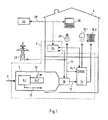
- FIG. 1 shows a schematic view of an embodiment of a micro CHP plant 2, which is part of a power plant system according to the invention.
- the micro-CHP plant 2 shown can, for example, provide an electrical power of between 1 and 20 kW.
- the micro CHP plant 2 is presently installed in a building 4.
- the building 4 may be, for example, a one-, two- or multi-family house, an office building or the like. It is understood that a micro-CHP plant 2 can also be used to supply a plurality of (smaller) buildings.
- the present micro CHP plant 2 comprises a CHP device 6 with a motor 6.1 and a generator 6.2.
- the present CHP facility 6 is operated with natural gas.
- a natural gas connection 8 is provided. It is understood that according to other variants of the invention, another fuel can be used.
- While the engine 6.1 generates thermal energy and supplies it via a line 12 to a thermal storage device 14, 6.2 electrical energy is generated by the generator and delivered via an electrical line 10, for example, to electrical loads 20 of the building 4.
- electrical energy is limited by the thermal capacity limit, since the power generation is always linked to the generation of thermal energy.
- the CHP device 6 is a continuously variable CHP device 6.
- the CHP device 6 between a minimum electric power and a maximum electric power (rated power) can be operated continuously.
- the CHP device 6 has to control a control unit 16.
- the controller 16 is configured to control the engine 6.1 and / or the generator 6.2 in response to received power setpoints.
- the control unit 16 is set up to transform received power setpoint values into suitable control signals and / or to record and make available current state data of the cogeneration unit 6, such as the actual electrical power and / or the actual thermal power.
- the thermal storage device 14 may include a heat exchanger (not shown). Via further lines, thermal consumers 18.1, 18.2 in the building 4 can be supplied with the thermal energy stored in the memory 14. Further, the thermal storage device 14 may include at least one temperature sensor (not shown) to measure the storage temperature. In particular, the memory device 14 can be operated between a minimum and a maximum temperature.
- the thermal storage device 14 may have an electrically operable heating element 14.1.
- the heating element 14.1 may in particular be adapted to heat the storage fluid, in particular water.
- the heating element 14.1 can convert electrical energy into thermal energy.
- a three-stage adjustable heating element 14.1 may be provided.
- the micro CHP plant 2 has an electrical connection to the public electrical network 22, in particular a low-voltage grid 22 on.
- the public electrical network 22 On the one hand, this makes it possible, on the one hand, to obtain electrical energy from the public electrical network 22, for example for operating the electrical consumers 20 and / or the electric heating element 14.1, and, on the other hand, to allow the electrical energy generated by the cogeneration device 6 to enter the public electrical network 22 to dine.
- the illustrated micro CHP plant 2 comprises a local control device 24 or local control device.
- the control device 24 may in particular be a computing device 14 and comprise computing means, such as a processor, memory means, etc.
- the control device 24 is configured to control the micro CHP plant 2.
- the controller 24 may provide power setpoints for the CHP device 6 in response to received control commands. Depending on these power setpoints, the CHP device 6 can then be operated by the control unit 16.
- the control device 24 can current values of the CHP device 6, such as the currently generated electrical energy and / or thermal energy currently in the network 22nd supplied electrical energy, the current consumed by the consumers 20 electrical energy, and actual values of the thermal storage device 14, such as the current storage temperature, detect and evaluate.
- the control device 24 is in particular configured to determine a thermal load forecast for a future period of time.
- the controller 24 may (periodically) create a thermal load forecast P th, Prog for a first future period, such as the next day.
- the thermal load forecast P th, Prog can be created based on historical data.
- the thermal load forecast P th, Prog for domestic hot water and heating heat can be realized as a weighted linear combination of the consumption values measured in the building 4 in the last few days.
- P th . pr ⁇ og t ⁇ 1 ⁇ P th . Day - 1 t + ⁇ 2 ⁇ P th . Day - 2 t + ⁇ 3 ⁇ P th . Day - 3 t .
- the immediate past is weighted more heavily than the more recent readings. It goes without saying that corresponding values can be specified for the first days in which no measured values for the above-described calculation are available.
- thermo load forecast P th Prog also user preferences, such as absence information, can be considered.
- weather forecasts of the control device 24 can be made available. For example, temperatures and irradiation data postal code-specific for current and forecast values of the next day and / or the next three days, preferably the central control device 26. Thus, weather fluctuations, such as temperature fluctuations, in the preparation of the thermal load forecast / n of the control device 24 are taken into account.
- the control device 24 of a micro CHP plant 2 is further configured to determine, based at least on the thermal capacity limit, an individual electrical power time prognosis, as will be explained below.
- the control device 24 can be connected via at least one communication network 28, such as the Internet 28, a mobile network 28, etc., with a central and remote control device 26.
- the central control device 26 can be arranged in particular in a control room.
- the central control device 26 or central control device, for example a computer or a similar computing device, is configured to receive from the micro CHP plant 2 at least the at least one created individual electrical power time forecast via the communication network 28.
- the central control device 26 is adapted to transmit control commands, such as electrical setpoint values, to the micro CHP plant 2, in particular to the control device 24 of the micro CHP plant 2, to the micro CHP plant 2 control or regulate.
- the micro CHP plant 2 can furthermore be connected to at least one computing device 30, such as a PC, a tablet PC, a laptop, a smartphone, etc.
- the computing device 30 may in particular be configured to visualize certain data of the micro CHP plant 2, such as current and historical consumption data, power setpoints, tariff data, to a user. These data are (exclusively) via the remotely located central control device 26 provided.
- the user can also make certain specifications, such as a desired setpoint temperature for the building 4, absence information or the like. These customer specifications may then be taken into account by the controller 24 in determining the desired power values.
- a (not shown) additional heater such as a condensing boiler, be provided in the micro-CHP plant 2.
- the additional heater can be used in particular for the additional production of thermal energy.
- the additional heater may for example be connected to the natural gas connection.
- the additional heater may be controlled by the control device 24.
- FIG. 2 shows a schematic view of an embodiment of a power plant system 34 according to the present invention.
- the power plant system 34 comprises a plurality of micro CHP plants 2, as exemplified by means of FIG. 1 have been described.
- the micro CHP plants 2 are arranged in buildings 4.
- three micro CHP plants 2 are arranged in a first low-voltage grid 36.1 and two further micro-CHP plants 2 in a further low-voltage grid 36.2.
- the respective low-voltage network 36.1, 36.2 is connected in each case via a local power transformer 40 to a medium-voltage network 38.1, 38.2.
- the illustrated central control device 26 is configured to communicate bidirectionally with all micro CHP plants 2.
- the control device 26 can receive from the micro-CHP plants 2 at least electrical individual power time forecasts and transmit control commands to the micro CHP plants 2.
- the central control device 26 is arranged to receive performance time requests via a communication channel 42, for example the Internet. Depending on the power time requests and a total power time forecast derived from the individual electrical power time forecasts received, control commands can be determined and transmitted to the micro CHP systems 2.
- the illustrated power plant system 34 in addition to the illustrated micro-CHP plants 2 may also include other micro-CHP plants and other facilities, such as wind power plants, combined heat and power plants, biomass plants, solar power plants, etc.
- the illustrated micro CHP plants 2 can be configured differently.
- the micro CHP plants 2 can provide different electrical services and / or have a storage device with and without a heating element.
- the central control device 26 receives individual electrical power time forecasts from preferably all of the micro CHP systems 2 of the power plant system 34. It will be appreciated that the individual electrical power time forecasts need not be received at the same time.
- the central control device 26 can send request requests to the individual micro CHP plants 2, in particular the respective local control devices 24, whereupon the respective control devices 24 of the micro CHP plants have at least one (current) individual electrical power time forecast of the respective micro CHP plants.
- CHP plant 2 can send in response to the central control device 26.
- a micro CHP plant 2 may determine a plurality of individual electrical power time forecasts with which the micro CHP plant 2 is operable. For example, at least two positive single power time forecasts, such as a minimum and a maximum single power time forecast, may be determined.
- the still available thermal storage capacity of the thermal storage 14 can be determined.
- T sp, max represents the maximum permissible storage temperature of the thermal storage 14
- T sp represents the currently measured temperature in the thermal storage 14.
- m is the storage volume of the thermal storage 14
- c is the specific heat capacity of the storage fluid, such as water.
- Table 1 An exemplary thermal load forecast of a single-family dwelling is shown in Table 1 below: Table 1 t [h] 1 2 3 4 5 6 7 8th 9 W th, prog [kWh] 1.2 2.1 0.9 0.3 0.9 1.3 1.4 1.2 1.4
- At least one individual electrical power time forecast preferably at least one maximum positive electrical single power time forecast and a minimum positive electrical single -Performance time forecast to be created.
- micro CHP plant 2 under minimum power (minimum individual power time forecast) and rated power (maximum single power time forecast) will be examined below.
- a micro CHP plant 2 with a lower power limit of 1.8 kW el / 5.2 kW th and a rated power of 4.7 kW el / 12.5 kW th are assumed.
- the electrical power time forecasts ie the respective runtime of the micro CHP plant 2 associated with the minimum power and the maximum power, can preferably be determined iteratively become.
- the iteration can be aborted because the deviation between W D4 and W D3 is less than 1% and thus a stable result is achieved.
- the minimum individual electrical power time prognosis is therefore 1.8 kW el for a period of time or predicted running time of 3.9 h.
- This value dome can be transmitted to the central control device 26.
- the maximum individual electrical power time forecast can be determined in an analogous manner. Performing the above steps with the rated power, the maximum individual electrical power time forecast results to 4.7 kW el for a period of time or predicted running time of 1.45 hours. This value dome can also be transmitted to the central control device 26.
- micro CHP plant 2 is set up to convert electrical energy into heat energy, for example by means of the optional heating element 14.1, preferably at least one negative power time prognosis can also be determined in addition to the positive individual power time prognosis.
- at least one negative power time prognosis can also be determined in addition to the positive individual power time prognosis.
- three negative individual performance time forecasts can be determined and transmitted, as will be described below by way of example.
- An exemplary heating element 14.1 absorbs electrical power in the available power levels of 3 kW, 6 kW and 9 kW and outputs the heat produced thereby (assuming an efficiency of 100%) to the memory 14.
- This value dome or negative individual performance time forecasts can also be transmitted to the central control device. It can be stated that As the control power increases, the available control energy decreases because the simultaneous thermal consumption has less influence.
- the above determinations of the individual performance time forecasts may be re-run regularly (e.g., every 15 minutes) and updated individual performance time forecasts may be made.
- the transmitted individual power time prognosis may include an identification code of the micro CHP plant 2.
- the central control device 26 can, in a step 302, sum all received individual power-time forecasts into a total Accumulate service time forecast.
- subnetwork performance time forecasts for the plurality of subnetworks can first be created in a first substep. For example, this may be performed by the central control device 26.
- micro CHP 1-3 the negative individual electrical power time forecasts of three micro CHP plants 2 (micro CHP 1-3) are shown in Table 2 below for two stages (-3 kW and -9 kW).
- Table 2 Running time [h] Power kW] Micro CHP 1 5.2 -3 Micro CHP 1 1.3 -9 Micro CHP 2 4.3 -3 Micro CHP 2 0.9 -9 Micro CHP 3 3.7 -3 Micro CHP 3 1.4 -9
- the calculation rule (q) is applied analogously.
- the formula (q) states that a micro CHP plant 2 is always included in the calculation with the maximum available power at the time in question. Since these are negative powers, "min” is used in the equation.
- Table 3 shows for example, that the subnet can be operated for 0.9 h with a negative control power of -27 kW.
- Table 4 shows the associated positive single-performance time forecasts of the three micro-CHP units 1-3 bundled into a subnet. The values shown are merely exemplary and can be determined by means of the formulas (e) to (p). Table 4 Running time [h] Power kW] Micro CHP 1 3 1.8 Micro CHP 1 0.9 4.7 Micro CHP 2 2.9 1.8 Micro CHP 2 0.9 4.7 Micro CHP 3 3.7 1.8 Micro CHP 3 0.7 4.7
- FIG. 4a the values from Tables 3 and 5 are plotted.
- the dots labeled 46 represent positive control powers versus time, while the dots labeled 48 represent negative control power versus time.
- the diagram of the FIG. 4a is a step function (the individual points may not be connected by interpolation lines).
- a positive control power of 14.1 kW el is available for a maximum of 0.7 h and a positive control power of 11.2 kW el for a maximum of 0.9 h.
- a negative control power of -27 kW el is available for a maximum of 0.9 h and a negative control power of -3 kW el for a maximum of 5.2 h.
- FIG. 3 is a power timing diagram of one embodiment of a power plant system 34 in accordance with the present invention.
- the dots labeled 50 represent positive control power versus time, while the dots labeled 52 represent negative control power versus time.
- a performance time request has been received from the central control device 26. It is found that no Performance time request has been received, so can proceed to step 301. For example, after a specifiable (periodic) time interval (eg, 15 minutes), once again updated individual performance time forecasts can be received from (all) micro CHP plants 2 of the power plant system 34 (step 301) and an updated overall performance time forecast prepared at step 302.
- a specifiable (periodic) time interval eg, 15 minutes
- step 303 If it is determined in step 303 that a performance time request has been received, then in a next step 304 the central control device 26 evaluates the performance time request along with the total performance time forecast.
- the power-time request may include a specific electrical control power for a certain period of time.
- the electrical control power may be a negative or positive electrical control power.
- a request is made as to whether the power plant system 34 can inject additional electrical energy into the grid 22 or whether the power plant system 34 can dissipate electrical energy from the grid 22.
- the central control device 26 checks whether the desired electrical control power for the desired runtime can be provided by the power plant system 34. In particular, the desired electrical control power for the desired transit time may be compared to the total power time prognosis of the power plant system 34. If it is determined that the nursezeitfanfrage can be met, for example, a positive response is created and (possibly after confirmation of the requesting party) in step 305, the power plant system 34, in particular distributed and remote individual micro CHP units 2, according to the central control device 26 is controlled.
- the central control device 26 is in particular configured to generate control commands comprising electrical setpoint values with associated runtime information and to transmit them to the respective local control devices 24 of the micro CHP systems 2.
- a negative response may be created and sent to the requesting party. It will be understood that in response, a counter offer may be transmitted at a different electrical reserve power level and / or a different duration that may be met by the power plant system 34.
- the power time request includes a second cost parameter in addition to the desired electrical control power and the desired run time.
- the second effort parameter indicates how high the effort for the desired electrical control power and the desired running time may be.
- At least part of the micro CHP plants 2 of the power plant system 34 has linked their at least one individual performance time forecast with a first cost parameter and transmitted it to the central control device 26 in step 301.
- At least the expense incurred for the provision of the additional electrical energy and / or for the decrease of the additional electrical energy in the respective micro CHP plant 2, such as wear of the units 6, 14.1, consumption costs (eg gas costs), can be achieved by the first expense parameter. etc. are taken into account. It is understood that other factors can be incorporated.
- the first consumption parameter therefore provides a condition in particular. Only if the requesting party agrees to take over the effort according to the first effort parameter, is the positive and / or negative control power available.
- the central control device 26 checks in this case, whether the desired electrical control power for the desired duration for the offered second effort parameter can be provided. In particular, only the individual performance time forecasts whose first cost parameters are below or equal to the second cost parameter are taken into account in the available overall performance time forecast of the power plant system 34. Represents the central Control device 26 determines that the desired electrical control power for the desired duration for the second effort parameter can be provided, the central control device 26 controls the micro-CHP systems 2 in step 305, as previously stated. It is understood that the micro-CHP plants 2, whose first cost parameter is above the second cost parameter, are not controlled.
- a negative response or a counter-offer to the requesting party can be created according to the previous statements.
- the power plant system 34 comprising a plurality of remote and distributed micro-CHP plants 2 is arranged to offer at least depending on the thermal limit capacity of the respective micro CHP plants 2 negative and positive control power, dangerous fluctuations in the amount of energy in the power grid 22 at least be reduced.
Landscapes
- Engineering & Computer Science (AREA)
- Power Engineering (AREA)
- Chemical & Material Sciences (AREA)
- Combustion & Propulsion (AREA)
- Mechanical Engineering (AREA)
- General Engineering & Computer Science (AREA)
- Management, Administration, Business Operations System, And Electronic Commerce (AREA)
- Supply And Distribution Of Alternating Current (AREA)
Abstract
Die Erfindung betrifft ein Verfahren zum Betreiben eines Kraftwerkssystems (34) umfassend eine Mehrzahl von verteilt angeordneten Mikro-KWK-Anlagen (2) und mindestens eine mit den verteilt angeordneten Mikro-KWK-Anlagen (2) über mindestens ein Kommunikationsnetz (28) verbundene zentrale Regelungsvorrichtung (26), umfassend Übertragen von elektrischen Einzel-Leistungszeitprognosen von zumindest einem Teil der verteilt angeordneten Mikro-KWK-Anlagen (2) an die zentrale Regelungsvorrichtung (26), wobei eine elektrische Einzel-Leistungszeitprognose einer Mikro-KWK-Anlage (2) zumindest in Abhängigkeit der thermischen Kapazitätsgrenze der Mikro-KWK-Anlage (2) von der Mikro-KWK-Anlage (2) erstellt wird, Bestimmen von mindestens einer ersten elektrischen Gesamt-Leistungszeitprognose des Kraftwerkssystems (24) durch die zentrale Regelungsvorrichtung (26) durch Akkumulieren der empfangenen Einzel-Leistungszeitprognosen, und Regeln von zumindest einem Teil der verteilt angeordneten Mikro-KWK-Anlagen (2) von der zentralen Regelungsvorrichtung (26) zumindest in Abhängigkeit der bestimmten ersten Gesamt-Leistungszeitprognose des Kraftwerkssystems (34) und einer empfangenen Leistungszeitanfrage.

Description
Die Erfindung betrifft ein Verfahren zum Betreiben eines Kraftwerkssystems umfassend eine Mehrzahl von verteilt angeordneten Mikro-KWK-Anlagen und mindestens eine mit den verteilt angeordneten Mikro-KWK-Anlagen über mindestens ein Kommunikationsnetz verbundene zentrale Regelungsvorrichtung. Darüber hinaus betrifft die Erfindung ein Kraftwerkssystem und ein Computerprogramm.The invention relates to a method for operating a power plant system comprising a plurality of distributed micro-CHP plants and at least one connected to the distributed micro-CHP plants connected via at least one communication network central control device. Moreover, the invention relates to a power plant system and a computer program.
In der heutigen Zeit werden vermehrt dezentrale Kleinkraftwerke, wie Mikro-Kraft-Wärme-Kopplungsanlagen (Mikro-KWK-Anlagen) eingesetzt, um insbesondere einzelne Gebäude, wie Ein-, Zwei-, und Mehrfamilienhäuser sowie Bürogebäude, mit Energie zu versorgen. Insbesondere stellt eine Mikro-KWK-Anlage neben elektrischer Energie auch Wärmeenergie bzw. thermische Energie für das Gebäude bereit.Today, decentralized small power plants, such as micro-cogeneration plants (micro-CHP systems) are increasingly being used to supply particular individual buildings, such as single-family, two-family, multi-family and office buildings, with energy. In particular, a micro-CHP plant provides not only electrical energy but also thermal energy or thermal energy for the building.
Eine Mikro-KWK-Anlage weist zur Bereitstellung der elektrischen Energie und der thermischen Energie eine Kraft-Wärme-Kopplungseinrichtung (KWK-Einrichtung) auf. KWK-Einrichtungen zeichnen sich durch einen hohen Gesamt-Nutzungsgrad aus, da sie neben thermischer Leistung gleichzeitig auch elektrische Leistung erzeugen. Eine KWK-Einrichtung wird zur Erzeugung der elektrischen und thermischen Leistung mit einem geeigneten Brennstoff, wie Erdgas, Erdöl, Biogas, Klärgas, Deponiegas, Pflanzenöl, Holz, Pellets, etc., betrieben.A micro-CHP unit has a combined heat and power unit (CHP unit) for providing the electrical energy and the thermal energy. CHP units are characterized by a high overall efficiency, as they generate not only thermal power but also electrical power. A cogeneration unit is operated to generate the electrical and thermal power with a suitable fuel such as natural gas, petroleum, biogas, sewage gas, landfill gas, vegetable oil, wood, pellets, etc.
Die von der KWK-Einrichtung erzeugte thermische Leistung kann zunächst in einer thermischen Speichereinrichtung zwischengespeichert und beispielsweise über Wärmetauscher für die Wohnwärme und das Warmwasser abgegeben werden. Die bei der Erzeugung der Wärme gleichzeitig erzeugte elektrische Energie kann im Gebäude unmittelbar verbraucht und/oder in das öffentliche elektrische Netz, insbesondere ein Niederspannungsnetz, eingespeist werden. Insbesondere ist die Generierung von elektrischer Energie stets mit der Generierung von thermischer Energie verbunden.The thermal power generated by the CHP device can initially be temporarily stored in a thermal storage device and discharged, for example via heat exchangers for the residential heat and hot water. The electrical energy generated simultaneously in the generation of heat can be consumed directly in the building and / or fed into the public electrical grid, in particular a low-voltage grid. In particular, the generation of electrical energy is always associated with the generation of thermal energy.
Ein stetig wachsendes Problem der elektrischen Stromnetze ist die erhebliche Schwankung der im Netz verfügbaren elektrischen Energie. So ist beispielsweise bei stürmischem und/oder wolkenlosem Wetter aufgrund der erheblichen Anzahl von Windkraftanlagen und/oder Solaranlagen die im Netz vorhandene elektrische Energie sehr groß. Dies kann zu einer Überlast und einem Zusammenbruch des Stromnetzes führen. Um dies zu vermeiden, ist es aus dem Stand der Technik bekannt die einzelnen dezentral angeordneten Kraftwerke durch lokale Steuerungseinrichtungen bzw. Regelungseinrichtungen vom öffentlichen Stromnetz zu trennen. Dies ist jedoch ineffizient, da zur Verfügung stehender Strom nicht genutzt werden kann.A constantly growing problem of electric power grids is the considerable fluctuation of the electrical energy available in the grid. Thus, for example, in stormy and / or cloudless weather due to the considerable number of wind turbines and / or solar systems existing in the network electrical energy is very large. This can lead to an overload and a breakdown of the power grid. To avoid this, it is known from the prior art to separate the individual decentralized power plants by local control devices or control devices from the public power grid. However, this is inefficient because available power can not be used.
Hingegen ist bei starker Nachfrage und einer Wetterlage mit geringen Wind und wenig Sonne die im Netz vorhandene elektrische Energie gering. Um dieses Problem zu vermeiden, werden in der Regel herkömmliche Kraftwerke auch während Phasen mit hoher Stromproduktion nicht runtergefahren, um beispielsweise bei einem Abflauen des Windes weiterhin eine ausreichende Strommengen bereitzustellen. Dies ist jedoch ebenfalls ineffizient und vergrößert das zuvor beschriebene Problem der Überlast. Ferner können sich Netzschwankungen können sich auch an der Strombörse im Preis widerspiegeln.By contrast, with strong demand and a weather situation with low wind and little sun, the electrical energy available in the network is low. To avoid this problem, usually conventional power plants are not shut down even during periods of high power production, for example, to continue to provide sufficient amounts of electricity when the wind abates. However, this is also inefficient and increases the problem of overload described above. Furthermore, grid fluctuations can also be reflected in the price on the electricity exchange.
Daher liegt der Erfindung die Aufgabe zugrunde, ein Verfahren zum Betreiben eines Kraftwerkssystems mit einer Mehrzahl von verteilt angeordneten Mikro-KWK-Anlagen und ein entsprechendes Kraftwerkssystem zur Verfügung zu stellen, welches in effizienter Weise die Schwankungen der im Stromnetz vorhandenen Energiemenge zumindest reduziert.The invention is therefore based on the object of providing a method for operating a power plant system having a plurality of distributed micro CHP plants and a corresponding power plant system which efficiently reduces the fluctuations of the amount of energy present in the power grid.
Die Aufgabe wird gemäß einem ersten Aspekt der Erfindung durch ein Verfahren zum Betreiben eines Kraftwerkssystems umfassend eine Mehrzahl von verteilt angeordneten Mikro-KWK-Anlagen und mindestens eine zentrale Regelungsvorrichtung gemäß Patentanspruch 1 gelöst. Das Verfahren zum Betreiben eines Kraftwerkssystems umfassend eine Mehrzahl von verteilt angeordneten Mikro-KWK-Anlagen und mindestens eine mit den verteilt angeordneten Mikro-KWK-Anlagen über mindestens ein Kommunikationsnetz verbundene zentrale Regelungsvorrichtung umfasst die Schritte:
- Übertragen von elektrischen Einzel-Leistungszeitprognosen von zumindest einem Teil der verteilt angeordneten Mikro-KWK-Anlagen an die zentrale Regelungsvorrichtung,
- wobei eine elektrische Einzel-Leistungszeitprognose einer Mikro-KWK-Anlage zumindest in Abhängigkeit der thermischen Kapazitätsgrenze der Mikro-KWK-Anlage von der Mikro-KWK-Anlage erstellt wird,
- Bestimmen von mindestens einer ersten elektrischen Gesamt-Leistungszeitprognose des Kraftwerkssystems durch die zentrale Regelungsvorrichtung durch Akkumulieren der empfangenen Einzel-Leistungszeitprognosen,
- Regeln von zumindest einem Teil der verteilt angeordneten Mikro-KWK-Anlagen von der zentralen Regelungsvorrichtung zumindest in Abhängigkeit der bestimmten ersten Gesamt-Leistungszeitprognose des Kraftwerkssystems und einer empfangenen Leistungszeitanfrage.
- Transmitting individual electrical power time forecasts of at least a portion of the distributed micro CHP systems to the central control device,
- wherein an individual electrical performance time forecast of a micro CHP plant is created by the micro CHP plant at least as a function of the thermal capacity limit of the micro CHP plant,
- Determining at least a first overall electrical performance time forecast of the power plant system by the central control device by accumulating the received single power time forecasts;
- Controlling at least a portion of the distributed micro CHP plants from the central control device at least in response to the determined first overall power time forecast of the power plant system and a received power time request.
Indem im Gegensatz zum Stand der Technik eine Mehrzahl von dezentral angeordneten Mikro-KWK-Anlagen von einer entfernt angeordneten zentralen Regelungsvorrichtung bzw. Steuerungsvorrichtung in Abhängigkeit von elektrischen Leistungszeitprognosen basierend auf der jeweiligen thermischen Grenzkapazität der Mikro-KWK-Anlagen und einer Regelleistungsanfrage für einen zukünftigen Zeitraum geregelt bzw. gesteuert wird, können gefährliche Schwankungen der Netzspannung vor ihrem Entstehen zumindest reduziert werden. Zudem ist erkannt worden, dass durch das erfindungsgemäße Verfahren die einzelnen Mikro-KWK-Anlage mit einer erhöhten Effizienz betrieben werden können.In contrast to the prior art, a plurality of remotely located micro CHP plants from a remote central control device depending on electrical power time forecasts based on the respective thermal marginal capacity of the micro CHP plants and a control power request for a future period is controlled or controlled, dangerous fluctuations in the mains voltage can be at least reduced before they occur. In addition, it has been recognized that the individual micro-CHP plant can be operated with an increased efficiency by the inventive method.
Die mindestens zwei Mikro-KWK-Anlagen, vorzugsweise können eine Vielzahl von Mikro-KWK-Anlagen vorgesehen sein, weisen insbesondere jeweils eine elektrische Leistung von bis zu 20 kW auf. Eine derartige Mikro-KWK-Anlage ist besonders für Wohngebäude oder Bürogebäude geeignet.The at least two micro-CHP plants, preferably a plurality of micro-CHP plants can be provided, in particular each have an electrical Power up to 20 kW. Such a micro-CHP plant is particularly suitable for residential buildings or office buildings.
Eine Mikro-KWK-Anlage umfasst in der Regel eine Kraft-Wärme-Kopplungseinrichtung (KWK-Einrichtung) mit mindestens einem Motor und mindestens einem Generator. Die KWK-Einrichtung kann mit einem geeigneten Brennstoff, insbesondere Erdgas, betrieben werden. Die beim Verbrennen des Brennstoffs entstehende Energie wird in thermische und elektrische Energie gewandelt.A micro-CHP plant usually comprises a combined heat and power unit (CHP) with at least one engine and at least one generator. The cogeneration unit can be operated with a suitable fuel, in particular natural gas. The energy produced by burning the fuel is converted into thermal and electrical energy.
Mit der KWK-Einrichtung ist eine thermische Speichereinrichtung zum Speichern der erzeugten thermischen Energie verbunden. Wird elektrische Energie von der KWK-Einrichtung generiert, so wird die gleichzeitig generierte thermische Energie in der thermischen Speichereinrichtung gespeichert. Von der thermischen Speichereinrichtung kann die thermische Energie beispielsweise über einen Wärmetauscher bei Bedarf an die im Gebäude angeordneten Verbraucher abgegeben werden.Connected to the CHP device is a thermal storage device for storing the generated thermal energy. If electrical energy is generated by the CHP device, the simultaneously generated thermal energy is stored in the thermal storage device. From the thermal storage device, the thermal energy can be delivered, for example via a heat exchanger as needed to the consumer arranged in the building.
Zum (lokalen) Regeln bzw. Steuern zumindest der KWK-Einrichtung kann eine (lokale) Regelungseinrichtung bzw. Steuerungseinrichtung vorgesehen sein. Die Regelungseinrichtung kann insbesondere Rechenmittel, Speichermittel, etc. umfassen. Beispielsweise kann ein Mikroprozessor, ein Computer, etc. als Regelungseinrichtung eingesetzt werden. Die Regelungseinrichtung verfügt insbesondere über eine bidirektionale Kommunikationsverbindung zu der KWK-Einrichtung und der thermischen Speichereinrichtung.For (local) regulation or control of at least the CHP device, a (local) control device or control device can be provided. The control device may in particular comprise computing means, memory means, etc. For example, a microprocessor, a computer, etc. can be used as a control device. The control device has, in particular, a bidirectional communication connection to the CHP device and the thermal storage device.
Die Regelungseinrichtung ist insbesondere dazu eingerichtet, eine thermische Grenzkapazität zu bestimmen. Beispielsweise kann die Regelungseinrichtung eingerichtet sein, eine thermische Lastprognose für das Gebäude für einen ersten Zeitraum zu erstellen. Bei dem ersten Zeitraum kann es sich beispielsweise um die nächste Woche, den nächsten Tag, die nächste Stunde, etc. handeln. Eine Lastprognose gibt insbesondere an, wie viel thermische Energie voraussichtlich in dem ersten Zeitraum in dem Gebäude verbraucht/benötigt wird. Insbesondere kann es eine über die Zeit variable Funktion sein.The control device is in particular configured to determine a thermal limit capacity. For example, the controller may be configured to generate a thermal load forecast for the building for a first time period. For example, the first time period may be the next week, the next day, the next hour, and so on. A load forecast Specifically, it indicates how much thermal energy is expected to be consumed / needed in the building in the first period. In particular, it may be a variable function over time.
Zumindest in Abhängigkeit der thermischen Kapazitätsgrenze, insbesondere in Abhängigkeit der Lastprognose und vorzugsweise zudem in Abhängigkeit der noch zur Verfügung stehenden thermischen Speicherkapazität der Speichereinrichtung einer ersten Mikro-KWK-Anlage, kann von der ersten Mikro-KWK-Anlage mindestens eine elektrische Einzel-Leistungszeitprognose der ersten Mikro-KWK-Anlage erstellt und an die zentrale Regelungsvorrichtung übertragen werden. Ferner kann mindestens eine weitere Mikro-KWK-Anlage eingerichtet sein, eine zumindest in Abhängigkeit einer Kapazitätsgrenze, insbesondere einer thermischen Lastprognose, der weiteren Mikro-KWK-Anlage bestimmte weitere elektrische Einzel-Leistungszeitprognose der weiteren Mikro-KWK-Anlage an die zentrale Regelungsvorrichtung zu übertragen. Vorzugsweise können sämtliche Mikro-KWK-Anlagen jeweils mindestens eine Einzel-Leistungszeitprognose basierend auf der jeweiligen thermischen Kapazitätsgrenze an die zentrale Regelungsvorrichtung senden.At least as a function of the thermal capacity limit, in particular as a function of the load prediction and preferably also depending on the still available thermal storage capacity of the storage device of a first micro-CHP plant, from the first micro-CHP plant at least one electrical single-performance time forecast of first micro-CHP plant are created and transmitted to the central control device. Furthermore, at least one further micro-CHP plant can be set up, a further individual electrical power-time prognosis of the further micro-CHP plant to the central control device determined, at least as a function of a capacity limit, in particular a thermal load forecast, of the further micro CHP plant transfer. Preferably, all micro CHP plants can each send at least one individual performance time forecast based on the respective thermal capacity limit to the central control device.
Es ist insbesondere erkannt worden, dass Mikro-KWK-Anlagen zusätzliche elektrische Kapazitäten haben, die jedoch von der thermischen Kapazitätsgrenze, insbesondere von der thermischen Lastprognose und/oder von der noch zur Verfügung stehenden Wärmekapazität der jeweiligen Speichereinrichtung abhängen. Bei Bedarf kann beispielsweise zusätzliche elektrische Energie generiert oder verbraucht werden, bis die thermische Kapazitätsgrenze der Mikro-KWK-Anlage erreicht ist. Bei Erreichen der thermischen Kapazitätsgrenze ist keine weitere Stromgenerierung oder kein weiterer Stromverbrauch möglich.In particular, it has been recognized that micro-CHP plants have additional electrical capacities, which, however, depend on the thermal capacity limit, in particular on the thermal load prognosis and / or on the still available heat capacity of the respective storage device. If required, for example, additional electrical energy can be generated or consumed until the thermal capacity limit of the micro CHP plant is reached. When the thermal capacity limit is reached, no further power generation or power consumption is possible.
Eine Einzel-Leistungszeitprognose gibt eine potentielle zukünftige elektrische Leistungsfähigkeit einer Mikro-KWK-Anlage an. Beispielsweise kann die Einzel-Leistungszeitprognose für eine von der Zeit und/oder Leistung abhängige Funktion sein.A single performance time forecast indicates a potential future electrical performance of a micro CHP plant. For example, the Be a single performance time forecast for a time and / or performance dependent function.
Die zentrale Regelungsvorrichtung ist dazu eingerichtet, aus der Mehrzahl von Einzel-Leistungszeitprognose der mindestens zwei Mikro-KWK-Anlagen eine Gesamt-Leistungszeitprognose des gesamten Kraftwerkssystems zu erstellen. Insbesondere können die empfangenen Einzel-Leistungszeitprognose akkumuliert werden. Die Gesamt-Leistungszeitprognose gibt eine potentielle zukünftige elektrische Leistungsfähigkeit des gesamten Kraftwerkssystems an.The central control device is set up to generate an overall performance time forecast of the entire power plant system from the plurality of individual power time forecasts of the at least two micro CHP systems. In particular, the received single-performance time forecast can be accumulated. The overall performance time forecast indicates potential future electrical performance of the entire power plant system.
Zudem ist die zentrale Regelungsvorrichtung dazu eingerichtet, Leistungszeitanfragen zu empfangen. Unter einer Leistungszeitanfrage ist vorliegend eine Anfrage an das Kraftwerkssystem zu verstehen, ob es in der Lage ist, eine bestimmte Regelleistung für einen zukünftigen bestimmten Zeitraum zur Verfügung stellen, um beispielsweise zukünftige Netzschwankungen zu reduzieren. Wird eine Leistungszeitanfrage empfangen, so können von der zentralen Regelungsvorrichtung die Leistungszeitanfrage und die zuvor bestimmte (aktuelle) Gesamt-Leistungszeitprognose des Kraftwerkssystems ausgewertet und in Abhängigkeit der Auswertung das Kraftwerkssystem, insbesondere zumindest eine Mikro-KWK-Anlage, geregelt werden. Ist die Auswertung positiv, wird also beispielsweise festgestellt, dass der Leistungsanfrage entsprochen werden kann, so kann die zentrale Regelungsvorrichtung mindestens einen Steuerungsbefehl umfassend mindestens einen elektrischen Sollwert zusammen mit einer Laufzeitangabe an mindestens eine Mikro-KWK-Anlage übertragen, um die angefragte Regelleistung bereitzustellen.In addition, the central control device is set up to receive power time requests. In this case, a power-time request is a request to the power-plant system to understand whether it is able to provide a certain control power for a future specific period of time in order, for example, to reduce future network fluctuations. If a power-time request is received, the power-control request and the previously determined (current) total power-time prognosis of the power plant system can be evaluated by the central control device and the power plant system, in particular at least one micro-CHP plant, can be controlled as a function of the evaluation. If the evaluation is positive, for example, it is determined that the power request can be met, the central control device can transmit at least one control command comprising at least one electrical setpoint together with a runtime information to at least one micro CHP plant to provide the requested control power.
Es versteht sich, dass die Regelung bzw. Steuerung der Mikro-KWK-Anlagen auch darin bestehen kann, keine elektrischen Sollwerte den einzelnen Mikro-KWK-Anlagen vorzugeben. Dies kann beispielsweise dann erfolgen, wenn die potentielle zukünftige Leistungsfähigkeit des Kraftwerksystems nicht ausreicht, die Leistungsanfrage zu bedienen.It goes without saying that the regulation or control of the micro CHP plants can also consist in not specifying any electrical nominal values for the individual micro CHP plants. This can be done, for example, when the potential future performance of the power plant system is insufficient to service the power request.
Durch die Bündelung einer Vielzahl von dezentralen Mikro-KWK-Anlagen zu einem einzigen (virtuellen) Kraftwerk kann in einfacher Weise eine größere Regelleistung in Abhängigkeit der jeweiligen thermischen Kapazitätsgrenzen der Mikro-KWK-Anlagen bereitgestellt werden.By bundling a plurality of decentralized micro-CHP plants into a single (virtual) power plant, it is easily possible to provide greater control power as a function of the respective thermal capacity limits of the micro CHP plants.
Gemäß einem ersten Ausführungsbeispiel des erfindungsgemäßen Verfahrens kann von mindestens einer der Mikro-KWK-Anlagen eine Mehrzahl von elektrischen Einzel-Leistungszeitprognosen an die zentrale Regelungsvorrichtung übertragen werden. Die Mehrzahl von elektrischen Einzel-Leistungszeitprognosen kann mindestens eine positive elektrische Einzel-Leistungszeitprognose und/oder mindestens eine negative elektrische Einzel-Leistungszeitprognose umfassen. Indem vorzugsweise jede Mikro-KWK-Anlage eine Mehrzahl von elektrischen Einzel-Leistungszeitprognosen erstellt und überträgt, ist ein flexibler und effizienterer Betrieb des Kraftwerkssystems möglich. Beispielweise kann mindestens eine positive und mindestens eine negative elektrische Einzel-Leistungszeitprognose erstellt werden. Eine positive elektrische Einzel-Leistungszeitprognose umfasst eine positive Regelleistung, die zukünftig für eine bestimmte Laufzeit in Netz gespeist werden kann, während die negative elektrische Einzel-Leistungszeitprognose eine negative Regelleistung umfasst, die zukünftig für eine bestimmte Laufzeit dem Netz entzogen werden kann.According to a first exemplary embodiment of the method according to the invention, at least one of the micro CHP systems can transmit a plurality of individual electrical power time forecasts to the central control device. The plurality of single power electrical time forecasts may include at least one single positive power time prognosis and / or at least one negative individual power time forecasts. By preferably each micro CHP plant producing and transmitting a plurality of individual electrical power time forecasts, a more flexible and efficient operation of the power plant system is possible. For example, at least one positive and at least one negative individual electrical power time forecast can be generated. A positive single electrical power time forecast includes a positive control power that can be fed into the grid for a given run time in the future, while the single negative power time forecast includes a negative control power that can be withdrawn from the grid for a given run time in the future.
Die mindestens eine negative Einzel-Leistungszeitprognose umfassend eine negative Regelleistung von einer Mikro-KWK-Anlage kann insbesondere dann erstellt werden, wenn diese eingerichtet ist, Energie aus dem Stromnetz abzuführen bzw. zu verbrauchen. Beispielsweise kann in einer thermischen Speichereinrichtung eine elektrische Heizeinrichtung, wie ein Heizstab vorgesehen, welche/r elektrische Energie in thermische Energie wandeln kann. Bei einer Leistungsanfrage für eine negative Regelleistung, beispielsweise aufgrund einer prognostizierten hohen Stromproduktion durch erneuerbare Energien, kann zur Vermeidung einer Überlast das Kraftwerkssystem negative Regelleistung bereitstellen. Vorzugweise können, beispielsweise bei einem stufenweise betreibbaren Heizstab, eine Mehrzahl von negativen Einzel-Leistungszeitprognose von einer Mikro-KWK-Anlage, beispielsweise für jede Stufe eine, erstellt und an die zentrale Regelungsvorrichtung übertragen werden.The at least one negative individual power time forecast comprising a negative control power from a micro CHP plant can be created in particular if it is set up to dissipate or consume energy from the power grid. For example, in a thermal storage device, an electric heater, such as a heating rod, may be provided which can convert electrical energy into thermal energy. In case of a power request for a negative control power, for example due to a predicted high power production by renewable energies, the power plant system may provide negative control power to avoid an overload. Preferably, For example, in a stepwise operable heating element, a plurality of negative single-performance time forecast from a micro CHP plant, for example, for each stage one, created and transmitted to the central control device.
Vorzugsweise kann von der mindestens einen Mikro-KWK-Anlage mindestens eine maximale elektrische Einzel-Leistungszeitprognose (positiv und/oder negativ) und mindestens eine minimale elektrische Einzel-Leistungszeitprognose (positiv und/oder negativ) an die zentrale Regelungsvorrichtung übertragen werden. Beispielsweise kann eine Mikro-KWK-Anlage auswerten, wie lang sie mit minimaler (positiver und/oder negativer) Regelleistung betrieben werden kann bzw. wie lang sie mit maximaler (positiver und/oder negativer) Regelleistung betrieben werden kann. Vorzugweise weist eine Einzel-Leistungszeitprognose daher stets einen Leistungswert und eine zugehörige Laufzeit auf.Preferably, at least one maximum individual electrical power-time prognosis (positive and / or negative) and at least one minimum individual electrical power-time prognosis (positive and / or negative) can be transmitted to the central control device by the at least one micro-CHP system. For example, a micro CHP system can evaluate how long it can be operated with minimum (positive and / or negative) control power or how long it can be operated with maximum (positive and / or negative) control power. Therefore, a single performance time forecast preferably always has a performance value and an associated duration.
Gemäß einem weiteren Ausführungsbeispiel des erfindungsgemäßen Verfahrens kann die empfangene Leistungszeitanfrage zumindest eine bestimmte elektrische Regelleistung für eine bestimmte Laufzeit umfassen. Von der zentralen Regelungsvorrichtung kann zumindest überprüft werden, ob die bestimmte elektrische Regelleistung für die bestimmte Laufzeit von dem Kraftwerkssystem zur Verfügung gestellt werden kann, indem zumindest die bestimmte elektrische Regelleistung für die bestimmte Laufzeit und die Gesamt-Leistungsprognose ausgewertet werden. Beispielsweise kann die bestimmte elektrische Regelleistung für die bestimmte Laufzeit mit der ersten Gesamt-Leistungszeitprognose des Kraftwerkssystems verglichen werden. So kann überprüft werden, welche Gesamtleistung von den dezentral angeordneten Mikro-KWK-Anlagen für die angefragte Laufzeit zur Verfügung steht. Wird festgestellt, dass die angefragte Regelleistung für die bestimmte Laufzeit zur Verfügung gestellt werden kann, kann die zentrale Regelungsvorrichtung zumindest einen Teil der Mikro-KWK-Anlagen derart ansteuern, dass die Mikro-KWK-Anlagen die gewünschte Regelleistung ins Netz speisen und/oder aus dem Netz abführen. Es versteht sich, dass sämtliche Mikro-KWK-Anlagen oder, beispielsweise in Abhängigkeit einer vorgebbaren Prioritätenliste, nur ein Teil angesteuert werden kann/können.According to a further exemplary embodiment of the method according to the invention, the received power-time request may comprise at least one specific electrical control power for a specific transit time. The central control device can at least check whether the determined electrical control power for the specific runtime can be made available by the power station system by evaluating at least the determined electrical control power for the specific runtime and the overall power prognosis. For example, the particular electrical control power for the particular run time may be compared to the first overall power time prediction of the power plant system. For example, it is possible to check which total output is available from the decentralized micro-CHP plants for the requested term. If it is determined that the requested control power can be made available for the specific runtime, the central control device can control at least part of the micro CHP systems such that the micro CHP systems feed and / or off the desired control power into the network remove the network. It is understood that all Micro CHP systems or, for example, depending on a predetermined list of priorities, only a part can be controlled / can.
Gemäß einer bevorzugten Ausführungsform des erfindungsgemäßen Verfahrens kann von mindestes einer Mikro-KWK-Anlage der mindestens einen elektrischen Einzel-Leistungszeitprognose mindestens ein erster Aufwandsparameter der Mikro-KWK-Anlage für die elektrische Einzel-Leistungszeitprognose zugeordnet werden. Durch Abgeben und/oder Aufnehmen zusätzlicher elektrischer Energie entsteht auf Seiten der Mikro-KWK-Anlage ein erhöhter Aufwand. Neben Verschleiß der eingesetzten Betriebsmittel, fallen beispielsweise Brennstoffkosten und dergleichen an. Um den Aufwand zu berücksichtigen, kann eine Mikro-KWK-Anlage vorzugsweise sämtliche Einzel-Leistungszeitprognosen mit (individuellen) ersten Aufwandsparametern verknüpfen. Der erste Aufwandsparameter ist eine Bedingung, die erfüllt werden muss, damit die in der Einzel-Leistungszeitprognose angegebene elektrischen Leistung tatsächlich abgerufen/aufgenommen werden darf. Beispielsweise kann der Aufwandsparameter in Form eines Zahlenwerts angegeben werden. Von der zentralen Regelungsvorrichtung kann bei der Bestimmung der Gesamt-Leistungszeitprognose des Kraftwerkssystems der mindestens eine erste Aufwandsparameter berücksichtigt werden. So kann ein Teil der Gesamt-Leistungszeitprognose tatsächlich nur bei Erfüllung der zusätzlichen Bedingung im Kraftwerkssystems zur Verfügung stehen. Auch besteht die Möglichkeit, für unterschiedliche erste Aufwandsparameter unterschiedliche Gesamt-Leistungszeitprognose zu erstellen.According to a preferred embodiment of the method according to the invention of at least one micro-CHP plant, the at least one individual electrical performance time forecast at least a first cost parameter of the micro-CHP plant for the electrical single-performance time forecast can be assigned. By dispensing and / or receiving additional electrical energy on the side of the micro-CHP plant, an increased effort. In addition to wear of the equipment used, fall, for example, fuel costs and the like. In order to take the effort into account, a micro-CHP plant can preferably link all individual performance time forecasts with (individual) first expenditure parameters. The first effort parameter is a condition that must be met in order to actually retrieve / record the electrical power specified in the single power time forecast. For example, the expense parameter can be specified in the form of a numerical value. The at least one first effort parameter can be taken into account by the central control device when determining the total power time prognosis of the power station system. In fact, part of the overall performance time forecast can only be available when the additional condition in the power plant system is met. It is also possible to create different overall performance time forecasts for different first effort parameters.
Vorzugsweise kann die Leistungszeitanfrage einen zweiten Aufwandsparameter umfassen. Der zweite Aufwandsparameter, beispielsweise ebenfalls ein Zahlenwert, kann angeben, unter welcher Bedingung die gewünschte Regeleistung für eine bestimmte Laufzeit gewünscht ist. Gemäß einer Ausführungsform kann von der zentralen Regelungsvorrichtung überprüft werden, ob die bestimmte elektrische Regelleistung für die bestimmte Laufzeit für den zweiten Aufwandsparameter zur Verfügung gestellt werden kann, indem die bestimmte elektrische Regelleistung für den bestimmten Zeitraum für den zweiten Aufwandsparameter und die von mindestens einem ersten Aufwandsparameter abhängige Gesamt-Leistungszeitprognose ausgewertet werden. Beispielsweise kann die bestimmte elektrische Regelleistung für den bestimmten Zeitraum für den zweiten Aufwandsparameter mit dem mindestens einen ersten Aufwandsparameter der mindestens einen Gesamt-Leistungszeitprognose des Kraftwerkssystems verglichen werden. Es kann eine erste Gesamt-Leistungszeitprognose nur unter der Bedingung eines ersten Aufwandsparameters mit dem Zahlenwert X zur Verfügung stehen während eine weitere Gesamt-Leistungszeitprognose nur unter der Bedingung eines ersten Aufwandsparameters mit dem Zahlenwert Y zur Verfügung steht. Wird eine Leistung entsprechend der ersten Gesamt-Leistungszeitprognose angefragt und liegt der Zahlenwert des zweiten Aufwandsparameters bei größer oder gleich X, so steht die gewünschte Regelleistung für die bestimmte Laufzeit tatsächlich zur Verfügung. Ist der Zahlenwert des zweiten Aufwandsparameters kleiner X, beispielsweise Y, steht die Regelleistung für die bestimmte Laufzeit gemäß der ersten Gesamt-Leistungszeitprognose nicht zur Verfügung. Jedoch steht in diesem Fall die weitere Gesamt-Leistungszeitprognose zur Verfügung. In einfacher Weise kann verhindert werden, dass der Aufwand für den zusätzlichen Betrieb einer Mikro-KWK-Anlage den Nutzen des zusätzlichen Betriebs übersteigt.Preferably, the performance time request may include a second effort parameter. The second effort parameter, for example also a numerical value, can indicate the condition under which the desired register power is desired for a certain period of time. According to one embodiment, it can be checked by the central control device whether the determined electrical control power for the particular runtime can be made available for the second effort parameter by the determined electrical control power for the specific time period for the second effort parameter and the total power time prognosis dependent on at least one first effort parameter are evaluated. For example, the specific electrical control power for the specific time period for the second effort parameter can be compared with the at least one first effort parameter of the at least one overall power time prognosis of the power plant system. A first overall performance time forecast can only be available under the condition of a first effort parameter with the numerical value X, while a further overall performance time prognosis is available only under the condition of a first expense parameter with the numerical value Y. If a power is requested in accordance with the first overall power-time forecast and the numerical value of the second effort parameter is greater than or equal to X, the desired control power is actually available for the particular run-time. If the numerical value of the second effort parameter is smaller than X, for example Y, the control power is not available for the specific runtime according to the first overall power time prognosis. However, in this case the further overall performance time forecast is available. In a simple way can be prevented that the cost of the additional operation of a micro CHP plant exceeds the benefit of additional operation.
Beispielsweise kann es sich bei den Zahlenwerten des ersten bzw. zweiten Aufwandsparameters um einen monetären Betrag handeln, der zu dem Aufwand einer Mikro-KWK-Anlage für die Bereitstellung der negativen oder positiven Regelleistung korrespondiert bzw. den Betrag angibt, den die anfragende Partei, beispielsweise ein Stromkäufer/-verkäufer, bereit ist, für die gewünschte Leistung zu zahlen.For example, the numerical values of the first or second effort parameter may be a monetary amount that corresponds to the cost of a micro CHP plant for providing the negative or positive control power or indicates the amount that the requesting party, for example a buyer / seller of electricity, willing to pay for the desired service.
Um u.a. die Rechenzeit zur Bestimmung der Gesamt-Leistungszeitprognose des Kraftwerkssystems zu verringern, kann ein Teil der Mehrzahl von Mikro-KWK-Anlagen in beliebiger Weise zu einem Subnetz zusammengefasst werden. Vorzugsweise können physikalisch benachbarte und zusammenhängende Mikro-KWK-Anlagen zu einem Subnetz zusammengefasst werden. Gemäß einer Ausführungsform schlägt die Erfindung insbesondere vor, die Mikro-KWK-Anlagen eines Niederspannungsnetzes zu einem Subnetz zusammenzufassen. Ein Niederspannungsnetz kann zwischen 100 und 300 Gebäuden umfassen und eine Länge je nach Netzform von bis zu 1000 m aufweisen. Das Niederspannungsnetz kann eine Spannung (zwischen Phase und N) von 230V aufweisen und ist insbesondere durch einen Ortsnetztrafo an ein Mittelspannungsnetz angeschlossen. Die elektrischen Einzel-Leistungszeitprognosen der Mikro-KWK-Anlagen des Subnetzes können zu einer elektrischen Subnetz-Leistungszeitprognose akkumuliert werden. Vorzugsweise können in einem ersten Teilschritt aus den Einzel-Leistungszeitprognosen der Mikro-KWK-Anlagen eines Subnetzes zunächst entsprechende Subnetz-Leistungszeitprognosen erstellt werden. Aus der Mehrzahl von Subnetz-Leistungszeitprognosen kann dann die Gesamt-Leistungszeitprognose des Kraftwerkssystems bestimmt werden.In order, inter alia, to reduce the computation time for determining the total power-time prognosis of the power plant system, a part of the plurality of micro-CHP plants can be combined in any manner into a subnet. Preferably, physically adjacent and contiguous micro CHP plants can be grouped together to form a subnet. According to one Embodiment proposes the invention in particular to combine the micro-CHP systems of a low-voltage network to form a subnet. A low-voltage grid can have between 100 and 300 buildings and a length of up to 1000 m, depending on the network shape. The low-voltage network can have a voltage (between phase and N) of 230V and is connected in particular by a local network transformer to a medium-voltage network. The single-time electrical performance forecasts of the micro-CHPs of the subnet can be accumulated to an electrical subnetwork power-time forecast. Preferably, in a first sub-step, corresponding subnetwork performance time forecasts can first be created from the individual performance time forecasts of the micro CHP systems of a subnetwork. From the plurality of subnet power time forecasts, the total power time prediction of the power plant system can then be determined.
Durch die Bündelung von mehreren Mikro-KWK-Anlagen in Subnetze basierend auf ihrer Ortsnetzzugehörigkeit kann bei Bedarf eine regionale Steuerung bzw. Regelung des Kraftwerkssystems erfolgen. Beispielsweise können bei Bedarf nur die Mikro-KWK-Anlagen eines oder mehrerer bestimmter Subnetze von der zentralen Regelungsvorrichtung in obiger Weise angesteuert werden.By bundling several micro-CHP plants into subnetworks based on their local network affiliation, a regional control of the power plant system can take place if required. For example, if necessary, only the micro-CHP plants of one or more specific subnetworks can be controlled by the central control device in the above manner.
Darüber hinaus kann gemäß einer weiteren Ausführungsform des erfindungsgemäßen Verfahrens vorgesehen sein, dass die elektrischen Einzel-Leistungszeitprognosen von zumindest einem Teil der Mikro-KWK-Anlagen in vorgegebenen Zeitabständen an die zentrale Regelungsvorrichtung übertragen werden. Vorzugsweise können die Einzel-Leistungszeitprognosen automatisiert und in periodischen Zeitabständen an die zentrale Regelungsvorrichtung übertragen werden. Eine stets aktualisierte Gesamt-Leistungsprognose liegt in der zentralen Regelungsvorrichtung vor.In addition, according to a further embodiment of the method according to the invention, it may be provided that the individual electrical power time forecasts of at least part of the micro CHP systems are transmitted to the central control device at predetermined time intervals. Preferably, the individual performance time forecasts may be automated and transmitted at periodic intervals to the central control device. A constantly updated overall performance forecast is available in the central control device.
Ein weiterer Aspekt der Erfindung ist ein Kraftwerkssystem gemäß Patentanspruch 9. Das Kraftwerkssystem umfasst eine zentrale Regelungsvorrichtung. Das Kraftwerkssystem umfasst eine Mehrzahl von verteilt angeordneten und mit der zentralen Regelungsvorrichtung über mindestens ein Kommunikationsnetz verbundenen Mikro-KWK-Anlagen. Zumindest zwei der verteilt angeordneten Mikro-KWK-Anlagen sind eingerichtet, jeweils mindestens eine elektrische Einzel-Leistungszeitprognose an die zentrale Regelungsvorrichtung zu übertragen. Zumindest die zwei Mikro-KWK-Anlagen sind eingerichtet, jeweils mindestens eine elektrische Einzel-Leistungszeitprognose zumindest in Abhängigkeit der thermischen Grenzkapazität der jeweiligen Mikro-KWK-Anlagen zu erstellen. Die zentrale Regelungsvorrichtung ist eingerichtet, eine elektrische Gesamt-Leistungszeitprognose des Kraftwerkssystems durch Akkumulierung der empfangenen Einzel-Leistungszeitprognosen zu bestimmen. Die zentrale Regelungsvorrichtung ist eingerichtet, zumindest einen Teil der verteilt angeordneten Mikro-KWK-Anlagen zumindest in Abhängigkeit der bestimmten Gesamt Leistungszeitprognose des Kraftwerkssystems und einer empfangenen Leistungszeitanfrage zu regeln.Another aspect of the invention is a power plant system according to
Insbesondere kann das zuvor beschriebene Verfahren zum Betreiben des zuvor beschriebenen Kraftwerkssystems eingesetzt werden.In particular, the method described above can be used for operating the power station system described above.
Ein noch weiterer Aspekt der Erfindung ist ein Computerprogramm mit Instruktionen ausführbar auf einem Prozessor derart, dass ein zuvor beschriebenes Kraftwerkssystem gemäß dem zuvor beschriebenen Verfahren gesteuert bzw. geregelt wird.Yet another aspect of the invention is a computer program having instructions executable on a processor such that a previously described power plant system is controlled in accordance with the method previously described.
Die Merkmale der Verfahren und Vorrichtungen sind frei miteinander kombinierbar. Insbesondere können Merkmale der Beschreibung und/oder der abhängigen Ansprüche, auch unter vollständiger oder teilweiser Umgehung von Merkmalen der unabhängigen Ansprüche, in Alleinstellung oder frei miteinander kombiniert eigenständig erfinderisch sein.The features of the methods and devices are freely combinable. In particular features of the description and / or the dependent claims, even in complete or partial circumvention of features of the independent claims, in isolation or freely combined with each other independently be inventive.
Es gibt nun eine Vielzahl von Möglichkeiten, das erfindungsgemäße Verfahren zum Betreiben eines Kraftwerkssystems, das erfindungsgemäße Kraftwerkssystem und das erfindungsgemäße Computerprogramm auszugestalten und weiterzuentwickeln. Hierzu sei einerseits verwiesen auf die den unabhängigen Patentansprüchen nachgeordneten Patentansprüche, andererseits auf die Beschreibung von Ausführungsbeispielen in Verbindung mit der Zeichnung. In der Zeichnung zeigt:
- Fig.1
- eine schematische Ansicht eines Ausführungsbeispiels eines Gebäudes umfassend eine Mikro-KWK-Anlage von einem Kraftwerkssystem gemäß der vorliegenden Erfindung;
- Fig.2
- eine schematische Ansicht eines Ausführungsbeispiels eines Kraftwerkssystems gemäß der vorliegenden Erfindung;
- Fig.3
- ein schematisches Diagramm eines Ausführungsbeispiels eines Verfahrens gemäß der vorliegenden Erfindung zum Betreiben eines Kraftwerkssystems umfassend eine Mehrzahl von verteilt angeordneten Mikro-KWK-Anlagen;
- Fig. 4a
- ein schematisches Diagramm einer Subnetz-Leistungszeitprognose; und
- Fig. 4b
- ein schematisches Diagramm einer Gesamt-Leistungszeitprognose.
- Fig.1
- a schematic view of an embodiment of a building comprising a micro CHP plant of a power plant system according to the present invention;
- Fig.2
- a schematic view of an embodiment of a power plant system according to the present invention;
- Figure 3
- a schematic diagram of an embodiment of a method according to the present invention for operating a power plant system comprising a plurality of distributed micro-CHP plants;
- Fig. 4a
- a schematic diagram of a subnet performance time forecasting; and
- Fig. 4b
- a schematic diagram of an overall performance time forecast.
In den Figuren werden für gleiche Elemente gleiche Bezugszeichen verwendet.In the figures, like reference numerals are used for like elements.
Die vorliegende Mikro-KWK-Anlage 2 umfasst eine KWK-Einrichtung 6 mit einem Motor 6.1 und einem Generator 6.2. Betrieben wird die vorliegende KWK-Einrichtung 6 mit Erdgas. Hierzu ist ein Erdgasanschluss 8 vorgesehen. Es versteht sich, dass gemäß anderen Varianten der Erfindung auch ein anderer Brennstoff verwendet werden kann.The present
Während der Motor 6.1 thermische Energie erzeugt und diese über eine Leitung 12 an eine thermische Speichereinrichtung 14 liefert, wird durch den Generator 6.2 elektrische Energie erzeugt und über eine elektrische Leitung 10 beispielsweise an elektrische Verbraucher 20 des Gebäudes 4 abgegeben. Die Generierung von elektrischer Energie ist jedoch durch die thermische Kapazitätsgrenze begrenzt, da die Stromgenerierung stets mit der Generierung von thermischer Energie verknüpft ist.While the engine 6.1 generates thermal energy and supplies it via a
Vorzugsweise ist die KWK-Einrichtung 6 eine stufenlos einstellbare KWK-Einrichtung 6. Insbesondere kann die KWK-Einrichtung 6 zwischen einer minimalen elektrischen Leistung und einer maximalen elektrischen Leistung (Nennleistung) stufenlos betrieben werden. Die KWK-Einrichtung 6 weist zur Steuerung ein Steuergerät 16 auf. Das Steuergerät 16 ist zum Steuern des Motors 6.1 und/oder des Generators 6.2 in Abhängigkeit von empfangenen Leistungssollwerten eingerichtet. Insbesondere ist das Steuergerät 16 eingerichtet, empfangene Leistungssollwerte in geeignete Steuersignale zu transformieren und/oder aktuelle Zustandsdaten der KWK-Einrichtung 6, wie die elektrische Ist-Leistung und/oder die thermische Ist-Leistung, zu erfassen und zur Verfügung zu stellen.Preferably, the
Die thermische Speichereinrichtung 14 kann einen (nicht gezeigten) Wärmeaustauscher umfassen. Über weitere Leitungen können thermische Verbraucher 18.1, 18.2 im Gebäude 4 mit der im Speicher 14 gespeicherten thermischen Energie versorgt werden. Ferner kann die thermische Speichereinrichtung 14 über mindestens einen (nicht gezeigten) Temperatursensor zum Messen der Speichertemperatur verfügen. Insbesondere kann die Speichereinrichtung 14 zwischen einer minimalen und einer maximalen Temperatur betrieben werden.The
Darüber hinaus kann die thermische Speichereinrichtung 14 einen elektrisch betreibbaren Heizstab 14.1 aufweisen. Der Heizstab 14.1 kann insbesondere dazu eingerichtet sein, das Speicherfluid, insbesondere Wasser, zu erwärmen. Mit anderen Worten kann der Heizstab 14.1 elektrische Energie in thermische Energie wandeln. Beispielsweise kann ein dreistufig regelbarer Heizstab 14.1 vorgesehen sein.In addition, the
Über elektrische Leitungen 10 können in dem Gebäude 4 angeordnete elektrische Verbraucher 20 mit Strom versorgt werden. Darüber hinaus weist die Mikro-KWK-Anlage 2 einen elektrischen Anschluss zum öffentlichen elektrischen Netz 22, insbesondere einem Niederspannungsortnetz 22, auf. Dies ermöglicht im Bedarfsfall einerseits den Bezug von elektrischer Energie aus dem öffentlichen elektrischen Netz 22, beispielsweise zum Betreiben der elektrischen Verbraucher 20 und/oder des elektrischen Heizstabs 14.1, und ermöglicht andererseits die von der KWK-Einrichtung 6 erzeugte elektrische Energie ins öffentliche elektrische Netz 22 zu speisen.Via
Darüber hinaus umfasst die abgebildete Mikro-KWK-Anlage 2 eine lokale Regelungseinrichtung 24 bzw. lokale Steuerungseinrichtung. Die Regelungseinrichtung 24 kann insbesondere eine Recheneinrichtung 14 sein und Rechenmittel, wie einen Prozessor, Speichermittel, etc. umfassen. Die Regelungseinrichtung 24 ist dazu eingerichtet, die Mikro-KWK-Anlage 2 zu steuern bzw. zu regeln. Beispielsweise kann die Regelungseinrichtung 24 Leistungssollwerte für die KWK-Einrichtung 6 in Abhängigkeit von empfangenen Steuerbefehlen bereitstellen. In Abhängigkeit dieser Leistungssollwerte kann dann die KWK-Einrichtung 6 von dem Steuergerät 16 betrieben werden. Ferner kann die Regelungseinrichtung 24 aktuelle Ist-Werte der KWK-Einrichtung 6, wie die aktuell erzeugte elektrische Energie und/oder thermische Energie, die aktuell ins Netz 22 gespeiste elektrische Energie, die aktuell von den Verbrauchern 20 verbrauchte elektrische Energie, und Ist-Werte der thermische Speichereinrichtung 14, wie die aktuelle Speichertemperatur, erfassen und auswerten.In addition, the illustrated
Die Regelungseinrichtung 24 ist insbesondere dazu eingerichtet, eine thermische Lastprognose für einen zukünftigen Zeitraum zu bestimmen. Die Regelungseinrichtung 24 kann (regelmäßig) für einen ersten zukünftigen Zeitraum, wie dem nächsten Tag, eine thermische Lastprognose Pth,Prog erstellen. Vorzugsweise kann die thermische Lastprognose Pth,Prog basierend auf historischen Daten erstellt werden. Beispielsweise kann die thermische Lastprognose Pth,Prog für Trinkwarmwasser und Heizwärme als gewichtete Linearkombination der in den letzten Tagen gemessenen Verbrauchswerte im Gebäude 4 realisiert werden. Für die thermische Leistung (als Summe aus Heizbedarf und Trinkwarmwasserbedarf) gilt: ![]()
mit 
![]()
With
Es hat sich gezeigt, dass α 1 =0.6, α 2 =0.3, α 3 =0.1 besonders zielführende Werte sind. Die unmittelbare Vergangenheit wird vorliegend stärker gewichtet, als die weiter zurückliegenden Messwerte. Es versteht sich, dass für die ersten Tage, in denen noch keine Messwerte für die oben beschriebene Berechnung vorliegen, entsprechende Werte vorgeben werden können.It has been shown that α 1 = 0.6, α 2 = 0.3, α 3 = 0.1 are particularly targeted values. In the present case, the immediate past is weighted more heavily than the more recent readings. It goes without saying that corresponding values can be specified for the first days in which no measured values for the above-described calculation are available.
Es versteht sich ferner, dass bei der Erstellung der thermischen Lastprognose Pth,Prog auch Nutzervorgaben, wie Abwesenheitsangaben, berücksichtigt werden können. Ferner können Wetterprognosen der Regelungseinrichtung 24 zur Verfügung gestellt werden. Beispielsweise können Temperaturen und Einstrahlungsdaten postleitzahl-spezifisch für aktuelle und Prognose-Werte des nächsten Tags und/oder der nächsten drei Tage vorzugsweise der zentralen Regelungsvorrichtung 26 bereitgestellt. So können auch Wetterschwankungen, wie Temperaturschwankungen, bei der Erstellung der thermischen Lastprognose/n von der Regelungseinrichtung 24 berücksichtigt werden.It is further understood that when creating the thermal load forecast P th, Prog also user preferences, such as absence information, can be considered. Furthermore, weather forecasts of the control device 24 can be made available. For example, temperatures and irradiation data postal code-specific for current and forecast values of the next day and / or the next three days, preferably the
Die Regelungseinrichtung 24 einer Mikro-KWK-Anlage 2 ist ferner dazu eingerichtet, zumindest basierend auf der thermischen Kapazitätsgrenze eine elektrische Einzel-Leistungszeitprognose zu bestimmen, wie nachfolgend ausgeführt werden wird.The control device 24 of a
Die Regelungseinrichtung 24 kann über mindestens ein Kommunikationsnetz 28, wie dem Internet 28, einem Mobilfunknetz 28, etc., mit einer zentralen und entfernt angeordneten Regelungsvorrichtung 26 verbunden sein. Die zentrale Regelungsvorrichtung 26 kann insbesondere in einer Leitwarte angeordnet sein.The control device 24 can be connected via at least one
Die zentrale Regelungsvorrichtung 26 bzw. zentrale Steuerungsvorrichtung, beispielsweise ein Computer oder eine ähnliche Recheneinrichtung, ist dazu eingerichtet, von der Mikro-KWK-Anlage 2 zumindest die mindestens eine erstellte elektrische Einzel-Leistungszeitprognose über das Kommunikationsnetz 28 zu empfangen. Darüber hinaus ist die zentrale Regelungsvorrichtung 26 dazu eingerichtet, Steuerbefehle, wie elektrische Sollwerte, an die Mikro-KWK-Anlage 2, insbesondere an die Regelungseinrichtung 24 der Mikro-KWK-Anlage 2, zu übertragen, um die Mikro-KWK-Anlage 2 zu steuern bzw. zu regeln.The
Die Mikro-KWK-Anlage 2 kann ferner mit mindestens einer Recheneinrichtung 30, wie einem PC, einem Tablet-PC, einem Laptop, einem Smartphone, etc., verbunden sein. Die Recheneinrichtung 30 kann insbesondere dazu eingerichtet sein, bestimmte Daten der Mikro-KWK-Anlage 2, wie aktuelle und historische Verbrauchsdaten, Leistungssollwerte, Tarifdaten, einem Benutzer zu visualisieren. Diese Daten werden (ausschließlich) über die entfernt angeordnete zentrale Regelungsvorrichtung 26 bereitgestellt. Über die Recheneinrichtung 30 kann der Benutzer zudem bestimmte Vorgaben machen, wie eine gewünschte Solltemperatur für das Gebäude 4, Abwesenheitsangaben oder dergleichen. Diese Kundenvorgaben können dann von der Reglungseinrichtung 24 bei der Bestimmung der Leistungssollwerte Berücksichtigung finden.The
Zusätzlich kann eine (nicht dargestellte) Zusatzheizeinrichtung, wie ein Brennwertkessel, in der Mikro-KWK-Anlage 2 vorgesehen sein. Die Zusatzheizeinrichtung kann insbesondere zur zusätzlichen Gewinnung von thermischer Energie eingesetzt werden. Hierzu kann die Zusatzheizeinrichtung beispielsweise mit dem Erdgasanschluss verbunden sein. Die Zusatzheizeinrichtung kann durch die Reglungseinrichtung 24 gesteuert bzw. geregelt werden.In addition, a (not shown) additional heater, such as a condensing boiler, be provided in the
Im vorliegenden Ausführungsbeispiel sind drei Mikro-KWK-Anlagen 2 in einem ersten Niederspannungsnetz 36.1 und zwei weitere Mikro-KWK-Anlagen 2 in einem weiteren Niederspannungsnetz 36.2 angeordnet. Das jeweilige Niederspannungsnetz 36.1, 36.2 ist jeweils über einen Ortsnetztransformator 40 an ein Mittelspannungsnetz 38.1, 38.2 angeschlossen.In the present exemplary embodiment, three
Die dargestellte zentrale Regelungsvorrichtung 26 ist dazu eingerichtet, mit sämtlichen Mikro-KWK-Anlagen 2 bidirektional zu kommunizieren. Insbesondere kann die Regelungsvorrichtung 26 von den Mikro-KWK-Anlagen 2 zumindest elektrische Einzel-Leistungszeitprognosen empfangen und Steuerbefehle an die Mikro-KWK-Anlagen 2 übertragen.The illustrated
Darüber hinaus ist die zentrale Regelungsvorrichtung 26 eingerichtet, Leistungszeitanfragen über einen Kommunikationskanal 42, beispielsweise das Internet, zu empfangene. In Abhängigkeit der Leistungszeitanfragen und einer aus den empfangenen elektrischen Einzel-Leistungszeitprognosen abgeleitete Gesamt-Leistungszeitprognose können Steuerbefehle bestimmt und an die Mikro-KWK-Anlagen 2 übertragen werden.In addition, the
Es versteht sich, dass das dargestellte Kraftwerkssystem 34 neben den dargestellten Mikro-KWK-Anlagen 2 auch noch weitere Mikro-KWK-Anlagen und andere Anlagen, wie Windkraftwerke, Blockheizkraftwerke, Biomasseanlagen, Solarkraftwerke, etc. umfassen kann. Darüber hinaus versteht es sich, dass die dargestellten Mikro-KWK-Anlagen 2 unterschiedlich konfiguriert sein können. So können die Mikro-KWK-Anlagen 2 unterschiedliche elektrische Leistungen bereitstellen und/oder eine Speichereinrichtung mit und ohne einen Heizstab aufweisen.It is understood that the illustrated
Nachfolgend wird der Betrieb des zuvor beschriebenen Kraftwerkssystems 34 mittels des in
In einem ersten Schritt 301 empfängt die zentrale Regelungsvorrichtung 26 elektrische Einzel-Leistungszeitprognosen von vorzugsweise sämtlichen Mikro-KWK-Anlagen 2 des Kraftwerkssystems 34. Es versteht sich, dass die elektrischen Einzel-Leistungszeitprognosen nicht zeitgleich empfangen werden müssen.In a
Beispielsweise kann die zentrale Regelungsvorrichtung 26 an die einzelnen Mikro-KWK-Anlagen 2, insbesondere die jeweiligen lokalen Regelungseinrichtungen 24, Anforderungsanfragen senden, woraufhin die jeweiligen Regelungseinrichtungen 24 der Mikro-KWK-Anlagen mindestens eine (aktuelle) elektrische Einzel-Leistungszeitprognose der jeweiligen Mikro-KWK-Anlage 2 als Antwort an die zentrale Regelungsvorrichtung 26 senden kann.For example, the
Bevor die Verarbeitung der empfangenen elektrischen Einzel-Leistungszeitprognosen in der zentralen Regelungsvorrichtung 26 beschrieben wird, wird nachfolgend beispielhaft die Bestimmung von elektrischen Einzel-Leistungszeitprognosen einer Mikro-KWK-Anlage 2 erklärt.Before describing the processing of the received individual electrical power time forecasts in the
Vorzugsweise kann eine Mikro-KWK-Anlage 2 eine Mehrzahl von elektrischen Einzel-Leistungszeitprognosen bestimmen, mit der die Mikro-KWK-Anlage 2 betreibbar ist. Beispielsweise können zumindest zwei positive Einzel-Leistungszeitprognosen, wie eine minimale und eine maximale Einzel-Leistungszeitprognose, bestimmt werden.Preferably, a
Nach der zuvor beschriebenen Erstellung einer thermischen Lastprognose durch die lokale Regelungseinrichtung 24 kann unter Berücksichtigung der aktuellen Speichertemperatur des thermischen Speichers 14 die noch verfügbare thermische Speicherkapazität des thermischen Speichers 14 bestimmt werden. Zunächst kann die noch verfügbare Temperaturspreizung ΔT nach folgender Formel ermittelt werden: ![]()
wobei T sp,max die maximal zulässige Speichertemperatur des thermischen Speichers 14 und Tsp die aktuell gemessene Temperatur im thermischen Speicher 14 darstellt. Anschließend kann mittels der Temperaturspreizung ΔT die noch verfügbare thermische Speicherkapazität ΔW des thermischen Speichers 14 wie folgt ermittelt werden: ![]()
wobei m das Speichervolumen des thermischen Speichers 14 und c die spezifische Wärmekapazität des Speicherfluids, beispielsweise von Wasser, darstellt.After the above-described preparation of a thermal load forecast by the local control device 24, taking into account the current storage temperature of the ![]()
where T sp, max represents the maximum permissible storage temperature of the ![]()
where m is the storage volume of the
Eine beispielhafte thermische Lastprognose eines Einfamilienhauses ist in nachfolgender Tabelle 1 dargestellt:
In Abhängigkeit der thermischen Kapazitätsgrenze der Mikro-KWK-Anlage 2, insbesondere der thermischen Lastprognose und der noch verfügbaren thermische Speicherkapazität des Speichers 14, kann mindestens eine elektrische Einzel-Leistungszeitprognose, vorzugsweise zumindest eine maximale positive elektrische Einzel-Leistungszeitprognose und eine minimale positive elektrische Einzel-Leistungszeitprognose erstellt werden.Depending on the thermal capacity limit of the
Beispielhaft wird im Folgenden der Betrieb der Mikro-KWK-Anlage 2 unter Minimalleistung (minimale Einzel-Leistungszeitprognose) und Nennleistung (maximale Einzel-Leistungszeitprognose) untersucht. Hierbei wird beispielhaft von einer Mikro-KWK-Anlage 2 mit einer unteren Leistungsgrenze von 1,8 kWel/ 5,2 kWth sowie einer Nennleistung von 4,7 kWel / 12,5 kWth ausgegangen.By way of example, the operation of the
Unter Berücksichtigung der aktuell verfügbaren Speicherkapazität des thermischen Speichers 14 und der für die nächsten Stunden erwarteten thermischen Last (siehe Tabelle 1), können die elektrischen Leistungszeitprognosen, also die zur Minimalleistung und zur Maximalleistung jeweils zugehörige Laufzeit der Mikro-KWK-Anlage 2 vorzugsweise iterativ ermittelt werden.Taking into account the currently available storage capacity of the
Die folgenden Schritte zeigen das Vorgehen am Beispiel der unteren Leistungsgrenze, wobei von einer noch verfügbaren Speicherkapazität ΔW = 16kWh beispielhaft ausgegangen wird.The following steps show the procedure using the example of the lower power limit, assuming an available storage capacity Δ W = 16 kWh as an example.
In einem ersten Schritt wird die Laufzeit ohne zusätzliche Lastprognose nach folgender Formel bestimmt: 
Die mittlere Last gemäß Lastprognose (Tabelle 1) auf Basis der ermittelten Laufzeit t1 ist: 
![]()
![]()
In einem nächsten Schritt wird die Laufzeitbestimmung unter Berücksichtigung der Lastprognose durchgeführt: 
Die mittlere Last gemäß Lastprognose (Tabellen 1) auf Basis der ermittelten Laufzeit t2 ist: 
![]()
![]()
Dann wird in einem nächsten Schritt die Laufzeitbestimmung unter Berücksichtigung der Lastprognose durchgeführt: 
Die mittlere Last gemäß Lastprognose (Tabelle 1) auf Basis der ermittelten Laufzeit t3 ist: 
![]()
![]()
Dann wird in einem nächsten Schritt die Laufzeitbestimmung unter Berücksichtigung der Lastprognose durchgeführt: 
Die mittlere Last gemäß Lastprognose (Tabelle 1) auf Basis der ermittelten Laufzeit t3 ist: 
![]()
![]()
An dieser Stelle kann die Iteration abgebrochen werden, da die Abweichung zwischen WD4 und WD3 kleiner 1% ist und somit ein stabiles Ergebnis erreicht ist.At this point, the iteration can be aborted because the deviation between W D4 and W D3 is less than 1% and thus a stable result is achieved.
Die minimale elektrische Einzel-Leistungszeitprognose ist daher 1,8 kWel für eine Zeitdauer bzw. prognostizierte Laufzeit von 3,9 h. Dieses Wertetuppel kann an die zentrale Regelungsvorrichtung 26 übertragen werden.The minimum individual electrical power time prognosis is therefore 1.8 kW el for a period of time or predicted running time of 3.9 h. This value dome can be transmitted to the
Die maximale elektrische Einzel-Leistungszeitprognose kann in analoger Weise bestimmt werden. Führt man die obigen Schritte mit der Nennleistung durch, ergibt sich die maximale elektrische Einzel-Leistungszeitprognose zu 4,7 kWel für eine Zeitdauer bzw. prognostizierte Laufzeit von 1,45 h. Auch dieses Wertetuppel kann an die zentrale Regelungsvorrichtung 26 übertragen werden.The maximum individual electrical power time forecast can be determined in an analogous manner. Performing the above steps with the rated power, the maximum individual electrical power time forecast results to 4.7 kW el for a period of time or predicted running time of 1.45 hours. This value dome can also be transmitted to the
Falls die Mikro-KWK-Anlage 2 eingerichtet ist, elektrische Energie in Wärmeenergie beispielsweise mittels des optionalen Heizstab 14.1 zu wandeln, kann vorzugsweise zusätzlich zu den positiven Einzel-Leistungszeitprognose auch mindestens eine negative Leistungszeitprognose bestimmt werden. Für einen beispielsweise dreistufig regelbaren Heizstab 14.1 können vorzugsweise drei negative Einzel-Leistungszeitprognosen bestimmt und übertragen werden, wie nachfolgend beispielhaft beschrieben wird.If the
Ein beispielhafter Heizstab 14.1 nimmt elektrische Leistung in den verfügbaren Leistungsstufen von 3 kW, 6 kW und 9 kW auf und gibt die dabei produzierte Wärme (bei einem angenommenen Wirkungsgrad von 100%) an den Speicher 14 ab.An exemplary heating element 14.1 absorbs electrical power in the available power levels of 3 kW, 6 kW and 9 kW and outputs the heat produced thereby (assuming an efficiency of 100%) to the
Die negativen Einzel-Leistungszeitprognosen können entsprechend den positiven Einzel-Leistungszeitprognosen (siehe Formeln (e) bis (p)) bestimmt werden. Es ergeben sich die folgenden drei negativen Einzel-Leistungszeitprognosen:
- 8,7 h Laufzeit bei -3,0 kWel (26,1 kWhel),
- 3,4 h Laufzeit bei -6,0 kWel (20,4 kWhel),
- 2,2 h Laufzeit bei -9,0 kWel (19,8 kWhel).
- 8.7 h running time at -3.0 kW el (26.1 kWh el ),
- 3.4 h running time at -6.0 kW el (20.4 kWh el ),
- 2.2 h running time at -9.0 kW el (19.8 kWh el ).
Auch diese Wertetuppel bzw. negativen Einzel-Leistungszeitprognosen können an die zentrale Regelungsvorrichtung übertragen werden. Es kann festgestellt werden, dass mit steigender Regelleistung die verfügbare Regelenergie sinkt, da der gleichzeitig stattfindende thermische Verbrauch weniger Einfluss hat.This value dome or negative individual performance time forecasts can also be transmitted to the central control device. It can be stated that As the control power increases, the available control energy decreases because the simultaneous thermal consumption has less influence.
Es versteht sich, dass bei der Bestimmung einer negativen Einzel-Leistungszeitprognose grundsätzlich auch weitere elektrische Verbraucher 20 im Gebäude und beispielsweise eine prognostizierte elektrische Leistungsprognose für das Gebäude mit berücksichtigt werden können.It is understood that when determining a negative single-power time forecast in principle also other
Es versteht sich ferner, dass die obigen Bestimmungen der Einzel-Leistungszeitprognosen regelmäßig (z.B. alle 15 min) erneut durchgeführt und aktualisierte Einzel-Leistungszeitprognose erstellt werden können. Zudem versteht es sich, dass die übertragenen Einzel-Leistungszeitprognose eine Identifikationskennung der Mikro-KWK-Anlage 2 umfassen können.It will also be understood that the above determinations of the individual performance time forecasts may be re-run regularly (e.g., every 15 minutes) and updated individual performance time forecasts may be made. In addition, it is understood that the transmitted individual power time prognosis may include an identification code of the
Sind die positiven und/oder negativen elektrischen Einzel-Leistungszeitprognosen vorzugsweise von sämtlichen im Kraftwerksystem 34 angeordneten Mikro-KWK-Anlagen 2 an die zentrale Regelungsvorrichtung 26 übertragen worden, kann insbesondere die zentrale Regelungsvorrichtung 26 in einem Schritt 302 sämtliche empfangene Einzel-Leistungszeitprognosen zu einer Gesamt-Leistungszeitprognose akkumulieren.If the positive and / or negative individual electrical power-time forecasts have preferably been transmitted to the
Um die Rechenzeit zur Bestimmung der Gesamt-Leistungszeitprognose zu verringern, können in einem ersten Teilschritt zunächst Subnetz-Leistungszeitprognosen für die Mehrzahl an Subnetzen erstellt werden. Beispielsweise kann dies von der zentralen Regelungsvorrichtung 26 durchgeführt werden.In order to reduce the computing time for determining the overall performance time forecast, subnetwork performance time forecasts for the plurality of subnetworks can first be created in a first substep. For example, this may be performed by the
Beispielhaft (obige beispielhafte Werte werden nachfolgend nicht übernommen) sind in nachfolgender Tabelle 2 für zwei Stufen (-3kW und -9kW) die negativen elektrischen Einzel-Leistungszeitprognosen von drei Mikro-KWK-Anlagen 2 (Mikro-KWK 1-3) dargestellt.
Durch Akkumulierung der Werte aus der Tabelle 2 erhält man folgende Tabelle 3 des Subnetzes umfassend die drei Mikro-KWK-Anlagen. Insbesondere erhält man die Tabelle 3 durch folgende Rechenvorschrift (beispielhaft für den Zeitpunkt 3,7h): ![]()
![]()
Auch für alle anderen Zeitpunkte der Tabelle 3 wird die Rechenvorschrift (q) analog angewendet. Prinzipiell besagt die Formel (q), dass eine Mikro-KWK-Anlage 2 immer mit der zu dem betrachteten Zeitpunkt maximal verfügbaren Leistung in die Berechnung aufgenommen wird. Da es sich vorliegend um negative Leistungen handelt, wird in der Gleichung "min" verwendet. Aus der Tabelle 3 ergibt sich beispielsweise, dass das Subnetz für 0.9 h mit einer negativen Regelleistung von -27 kW betrieben werden kann.Also for all other times of Table 3, the calculation rule (q) is applied analogously. In principle, the formula (q) states that a
Tabelle 4 zeigt die zugehörigen positiven Einzel-Leistungszeitprognosen von den drei Mikro-KWK-Anlagen 1-3, die zu einem Subnetz gebündelt sind. Die dargestellten Werte sind lediglich beispielhaft und lassen sich mittels der Formeln (e) bis (p) bestimmen.
Durch Akkumulierung der Werte aus der Tabelle 4 erhält man folgende Tabelle 5 des Subnetzes umfassend die drei Mikro-KWK-Anlagen. Insbesondere erhält man die Tabelle 5 durch folgende Rechenvorschrift (beispielhaft für den Zeitpunkt 3,7h): ![]()
![]()
In der
Gemäß den obigen Tabellen steht eine positive Regelleistung von 14,1 kWel für maximal 0,7 h und eine positive Regelleistung von 11,2 kWel für maximal 0,9 h zur Verfügung. Eine negative Regelleistung von -27 kWel steht für maximal 0,9 h und eine negative Regelleistung von -3 kWel für maximal 5,2 h zur Verfügung.According to the tables above, a positive control power of 14.1 kW el is available for a maximum of 0.7 h and a positive control power of 11.2 kW el for a maximum of 0.9 h. A negative control power of -27 kW el is available for a maximum of 0.9 h and a negative control power of -3 kW el for a maximum of 5.2 h.
Es sei angemerkt, dass sich die Speicherkapazität aus der Fläche unterhalb der Kurve aus
Nachdem in einem ersten Teilschritt in Schritt 302 die Subnetz-Leistungszeitprognosen sämtlicher Subnetze bestimmt wurden, kann in einem nächsten Teilschritt entsprechend den Formeln (q) und (r) die Gesamt-Leistungszeitprognose des Kraftwerksystems 34 von der zentralen Regelungsvorrichtung 26 bestimmt werden. Mit anderen Worten können die Subnetz-Leistungszeitprognosen akkumuliert werden. Ein beispielhaftes Ergebnis ist in der
In einem nächsten Schritt 303 wird überprüft, ob eine Leistungszeitanfrage von der zentralen Regelungsvorrichtung 26 empfangen wurde. Wird festgestellt, dass keine Leistungszeitanfrage empfangen wurde, so kann mit Schritt 301 fortgefahren werden. Beispielsweise können nach einem vorgebbaren (regelmäßigen) Zeitabstand (z.B. 15 min) erneut aktualisierte Einzel-Leistungszeitprognosen von (sämtlichen) Mikro-KWK-Anlagen 2 des Kraftwerksystems 34 empfangen werden (Schritt 301) und in Schritt 302 eine aktualisierte Gesamt-Leistungszeitprognose erstellt werden.In a
Wird in Schritt 303 festgestellt, dass eine Leistungszeitanfrage empfangen wurde, so wird in einem nächsten Schritt 304 von der zentralen Regelungsvorrichtung 26 die Leistungszeitanfrage zusammen mit der Gesamt-Leistungszeitprognose ausgewertet.If it is determined in
Gemäß einem ersten Beispiel kann die Leistungszeitanfrage eine bestimmte bzw. gewünschte elektrische Regelleistung für eine bestimmte Zeitdauer bzw. Laufzeit umfassen. Bei der elektrischen Regelleistung kann es sich um eine negative oder positive elektrische Regelleistung handeln. Mit anderen Worten wird eine Anfrage gestellt, ob das Kraftwerksystem 34 zusätzliche elektrische Energie ins Netz 22 einspeisen kann oder ob das Kraftwerksystem 34 elektrische Energie aus dem Netz 22 abführen bzw. verbrauchen kann.According to a first example, the power-time request may include a specific electrical control power for a certain period of time. The electrical control power may be a negative or positive electrical control power. In other words, a request is made as to whether the
In diesem Fall prüft die zentrale Regelungsvorrichtung 26, ob die gewünschte elektrische Regelleistung für die gewünschte Laufzeit von dem Kraftwerkssystem 34 zur Verfügung gestellt werden kann. Insbesondere kann die gewünschte elektrische Regelleistung für die gewünschte Laufzeit mit der Gesamt-Leistungszeitprognose des Kraftwerkssystems 34 verglichen werden. Wird festgestellt, dass die Leistungszeitfanfrage erfüllt werden kann, wird beispielsweise eine positive Rückantwort erstellt und (ggf. nach einer Bestätigung der anfragenden Partei) in Schritt 305 das Kraftwerkssystem 34, insbesondere die verteilt und entfernt angeordneten einzelnen Mikro-KWK-Anlagen 2, entsprechend von der zentralen Regelungsvorrichtung 26 angesteuert. Die zentrale Regelungsvorrichtung 26 ist insbesondere eingerichtet, Steuerbefehle umfassend elektrische Sollwerte mit zugehörigen Laufzeitangaben zu erstellen und an die jeweiligen lokalen Regelungseinrichtungen 24 der Mikro-KWK-Anlagen 2 zu übertragen.In this case, the
Für den Fall, dass die Leistungszeitanfrage nicht von dem Kraftwerkssystem 34 erfüllt werden kann, kann eine negative Rückantwort erstellt und an die anfragende Partei gesendet werden. Es versteht sich, dass als Antwort ein Gegenangebot übertragen werden kann mit einem anderen elektrischen Regelleistungswert und/oder einer anderen Laufzeit, die von dem Kraftwerkssystem 34 erfüllt werden kann.In the event that the performance time request can not be met by the
In einem weiteren Beispiel umfasst die Leistungszeitanfrage neben der gewünschten elektrischen Regelleistung und der gewünschten Laufzeit einen zweiten Aufwandsparameter. Der zweite Aufwandsparameter gibt an, wie hoch der Aufwand für die gewünschte elektrische Regelleistung und die gewünschte Laufzeit sein darf.In another example, the power time request includes a second cost parameter in addition to the desired electrical control power and the desired run time. The second effort parameter indicates how high the effort for the desired electrical control power and the desired running time may be.
In diesem Beispiel hat zudem zumindest ein Teil der Mikro-KWK-Anlagen 2 des Kraftwerkssystems 34 ihre mindestens eine Einzel-Leistungszeitprognose mit einem ersten Aufwandsparameter verknüpft und an die zentrale Regelungsvorrichtung 26 in Schritt 301 übertragen. Durch den ersten Aufwandsparameter kann zumindest der für die Bereitstellung der zusätzlichen elektrischen Energie und/oder für die Abnahme der zusätzlichen elektrischen Energie bei der jeweiligen Mikro-KWK-Anlage 2 anfallende Aufwand, wie Verschleiß der Einheiten 6, 14.1, Verbrauchskosten (z.B. Gaskosten), etc. berücksichtig werden. Es versteht sich, dass weitere Faktoren einfließen können. Der erste Verbrauchsparameter stellt daher insbesondere eine Bedingung da. Nur wenn die anfragende Partei zustimmt, den Aufwand entsprechend dem ersten Aufwandsparameter zu übernehmen, steht die positive und/oder negative Regelleistung zur Verfügung.In this example, moreover, at least part of the
Die zentrale Regelungsvorrichtung 26 überprüft in diesem Fall, ob die gewünschte elektrische Regelleistung für die gewünschte Laufzeit für den gebotenen zweiten Aufwandsparameter zur Verfügung gestellt werden kann. Insbesondere werden bei der verfügbaren Gesamt-Leistungszeitprognose des Kraftwerkssystems 34 nur die Einzel-Leistungszeitprognosen berücksichtigt, deren erste Aufwandsparameter unterhalb oder gleich dem zweiten Aufwandsparameter sind. Stellt die zentrale Regelungsvorrichtung 26 fest, dass die gewünschte elektrische Regelleistung für die gewünschte Laufzeit für den zweiten Aufwandsparameter zur Verfügung gestellt werden kann, so regelt die zentrale Regelungsvorrichtung 26 die Mikro-KWK-Anlagen 2 in Schritt 305, wie zuvor ausgeführt worden kann. Es versteht sich, dass die Mikro-KWK-Anlagen 2, deren erster Aufwandsparameter über dem zweiten Aufwandsparameter liegt, nicht angesteuert werden.The
Wird von der zentralen Regelungsvorrichtung 26 festgestellt, dass die Leistungszeitanfrage nicht erfüllt werden kann, so kann entsprechend den vorherigen Ausführungen eine negative Antwort oder ein Gegenangebot an die anfragende Partei erstellt werden.If it is determined by the
Indem das Kraftwerkssystem 34 umfassend eine Vielzahl von entfernt und verteilt angeordneten Mikro-KWK-Anlagen 2 eingerichtet ist, zumindest in Abhängigkeit der thermischen Grenzkapazität der jeweiligen Mikro-KWK-Anlagen 2 negative und positive Regelleistung anzubieten, können gefährliche Schwankungen der Energiemenge im Stromnetz 22 zumindest reduziert werden.By the
Claims (10)
Applications Claiming Priority (1)
| Application Number | Priority Date | Filing Date | Title |
|---|---|---|---|
| DE102013108879.1A DE102013108879A1 (en) | 2013-08-16 | 2013-08-16 | Method for operating a power plant system |
Publications (2)
| Publication Number | Publication Date |
|---|---|
| EP2843788A2 true EP2843788A2 (en) | 2015-03-04 |
| EP2843788A3 EP2843788A3 (en) | 2015-03-11 |
Family
ID=50735975
Family Applications (1)
| Application Number | Title | Priority Date | Filing Date |
|---|---|---|---|
| EP14169314.3A Withdrawn EP2843788A3 (en) | 2013-08-16 | 2014-05-21 | Method for operating a power plant system |
Country Status (2)
| Country | Link |
|---|---|
| EP (1) | EP2843788A3 (en) |
| DE (1) | DE102013108879A1 (en) |
Cited By (3)
| Publication number | Priority date | Publication date | Assignee | Title |
|---|---|---|---|---|
| CN109347150A (en) * | 2018-11-27 | 2019-02-15 | 中国长江电力股份有限公司 | A kind of distributed power generation scheduling system and dispatching method |
| CN109544016A (en) * | 2018-11-27 | 2019-03-29 | 中国长江电力股份有限公司 | A kind of smart grid scheduling system and dispatching method based on user demand |
| CN109598429A (en) * | 2018-11-27 | 2019-04-09 | 中国长江电力股份有限公司 | A kind of island microgrid intelligent dispatching system and dispatching method |
Families Citing this family (3)
| Publication number | Priority date | Publication date | Assignee | Title |
|---|---|---|---|---|
| DE102017006619A1 (en) * | 2017-07-12 | 2019-01-17 | Stiebel Eltron Gmbh & Co. Kg | Method for operating domestic engineering systems in an electric power grid |
| CN109973164B (en) * | 2019-04-03 | 2021-10-22 | 四川国锐工程设计有限公司 | Natural gas distributed energy optimization system |
| DE102020212497A1 (en) | 2020-10-02 | 2022-04-07 | Siemens Aktiengesellschaft | Method for operating an energy system and energy system |
Family Cites Families (7)
| Publication number | Priority date | Publication date | Assignee | Title |
|---|---|---|---|---|
| DE102005056084A1 (en) * | 2005-11-24 | 2007-06-14 | Dehn + Söhne Gmbh + Co. Kg | Electrical energy controlling and public power supply`s load structure harmonizing method, involves accomplishing power requirement prediction by central processor from sum of all decentralized available standard energies |
| US7983799B2 (en) * | 2006-12-15 | 2011-07-19 | General Electric Company | System and method for controlling microgrid |
| US7925387B2 (en) * | 2009-07-14 | 2011-04-12 | General Electric Company | Method and systems for utilizing excess energy generated by a renewable power generation system to treat organic waste material |
| CA2831621C (en) * | 2011-03-31 | 2019-06-04 | Energent Incorporated | A computer implemented electrical energy hub management system and method |
| CN102506519B (en) * | 2011-10-23 | 2013-12-11 | 重庆市电力公司电力科学研究院 | Heat and power cogenerator unit and wind power generator unit combined heat supply system and scheduling method thereof |
| EP2764298B1 (en) * | 2012-01-23 | 2018-02-28 | Siemens Aktiengesellschaft | Cogeneration plant and operation method therefor |
| DE102012023486A1 (en) * | 2012-12-03 | 2014-06-05 | Rwe Effizienz Gmbh | Cogeneration System |
-
2013
- 2013-08-16 DE DE102013108879.1A patent/DE102013108879A1/en active Pending
-
2014
- 2014-05-21 EP EP14169314.3A patent/EP2843788A3/en not_active Withdrawn
Non-Patent Citations (1)
| Title |
|---|
| None |
Cited By (5)
| Publication number | Priority date | Publication date | Assignee | Title |
|---|---|---|---|---|
| CN109347150A (en) * | 2018-11-27 | 2019-02-15 | 中国长江电力股份有限公司 | A kind of distributed power generation scheduling system and dispatching method |
| CN109544016A (en) * | 2018-11-27 | 2019-03-29 | 中国长江电力股份有限公司 | A kind of smart grid scheduling system and dispatching method based on user demand |
| CN109598429A (en) * | 2018-11-27 | 2019-04-09 | 中国长江电力股份有限公司 | A kind of island microgrid intelligent dispatching system and dispatching method |
| CN109347150B (en) * | 2018-11-27 | 2021-07-06 | 中国长江电力股份有限公司 | Distributed power generation dispatching system and dispatching method |
| CN109598429B (en) * | 2018-11-27 | 2021-07-06 | 中国长江电力股份有限公司 | Intelligent dispatching system and dispatching method for island micro-grid |
Also Published As
| Publication number | Publication date |
|---|---|
| EP2843788A3 (en) | 2015-03-11 |
| DE102013108879A1 (en) | 2015-02-19 |
Similar Documents
| Publication | Publication Date | Title |
|---|---|---|
| EP2738362B1 (en) | Cogeneration system | |
| EP2843788A2 (en) | Method for operating a power plant system | |
| EP2615385B1 (en) | System manager for energy converters with adjustable power | |
| DE102011051673A1 (en) | Power Management System | |
| CH708628A2 (en) | System and method for minimizing network hot Reserve losses through predictive sequencing of power plants to supplement with wind power generation capacity based on spatially geographic regional wind conditions | |
| EP3091294B1 (en) | Method and device for controlling the supply heat of heat consumers | |
| DE102011051671A1 (en) | Optimization system using an iterative expert engine | |
| DE102014112979A1 (en) | System and method for minimizing producer power reserve losses by predictive ordering of power plants for offsetting solar power generation capacity based on geographic regional tanning and clouding conditions | |
| EP2528183B1 (en) | Method and device for energy transfer | |
| DE102011090141A1 (en) | Method and device for using electrical energy of a device connected to a household power network for generating renewable electrical energy | |
| DE102016015503A1 (en) | Heating and / or cooling system with predictive energy management | |
| DE102015101738A1 (en) | Method for operating a power generation plant and power generation plant | |
| WO2016120240A1 (en) | Method for improving the capacity utilization of a low-voltage network | |
| EP3561983A1 (en) | Method for operating an energy supply system | |
| EP4193315A1 (en) | Method for controlling power exchanges and heat exchanges between a plurality of energy systems by means of a central control platform | |
| DE102018116845A1 (en) | Method of operating a heat pump | |
| DE102017125282A1 (en) | Energy management system for predictive determination and regulation of a flow temperature of a building heating | |
| EP3284152B1 (en) | Energy transmission control between an energy supply network and end-user facilities on the basis of energy flow and network quality | |
| DE102010001874A1 (en) | Storage e.g. lithium ion accumulator, for storing electrical power in e.g. wind power station for supplying electrical power to consumer in single family house, has control controlling delivery and receiving of energy from/by mains | |
| WO2014041037A2 (en) | Energy converter apparatus and method for providing regulating power | |
| DE102013003469A1 (en) | Method for room- or building heating under partial use of renewable, volatile electrical energy, involves supplying electrical energy in electro-thermal storage for heating room or building by using controller | |
| DE102011122580B4 (en) | Method for operating an electrical supply network and associated control unit | |
| DE202021002540U1 (en) | Dishwasher with power adjustment to maximize self-consumption with local regenerative power generation | |
| EP3872719A1 (en) | Method for determining a failure risk | |
| WO2020104450A1 (en) | Feed-in method for a wind power system, and wind power system |
Legal Events
| Date | Code | Title | Description |
|---|---|---|---|
| PUAL | Search report despatched |
Free format text: ORIGINAL CODE: 0009013 |
|
| 17P | Request for examination filed |
Effective date: 20140521 |
|
| AK | Designated contracting states |
Kind code of ref document: A2 Designated state(s): AL AT BE BG CH CY CZ DE DK EE ES FI FR GB GR HR HU IE IS IT LI LT LU LV MC MK MT NL NO PL PT RO RS SE SI SK SM TR |
|
| AX | Request for extension of the european patent |
Extension state: BA ME |
|
| PUAI | Public reference made under article 153(3) epc to a published international application that has entered the european phase |
Free format text: ORIGINAL CODE: 0009012 |
|
| AK | Designated contracting states |
Kind code of ref document: A3 Designated state(s): AL AT BE BG CH CY CZ DE DK EE ES FI FR GB GR HR HU IE IS IT LI LT LU LV MC MK MT NL NO PL PT RO RS SE SI SK SM TR |
|
| AX | Request for extension of the european patent |
Extension state: BA ME |
|
| RIC1 | Information provided on ipc code assigned before grant |
Ipc: H02J 3/24 20060101ALI20150203BHEP Ipc: G06Q 50/06 20120101ALI20150203BHEP Ipc: H02J 3/46 20060101AFI20150203BHEP Ipc: H02J 3/38 20060101ALI20150203BHEP Ipc: F01K 13/02 20060101ALI20150203BHEP |
|
| R17P | Request for examination filed (corrected) |
Effective date: 20150811 |
|
| RBV | Designated contracting states (corrected) |
Designated state(s): AL AT BE BG CH CY CZ DE DK EE ES FI FR GB GR HR HU IE IS IT LI LT LU LV MC MK MT NL NO PL PT RO RS SE SI SK SM TR |
|
| RAP1 | Party data changed (applicant data changed or rights of an application transferred) |
Owner name: EASYOPTIMIZE GMBH |
|
| STAA | Information on the status of an ep patent application or granted ep patent |
Free format text: STATUS: THE APPLICATION IS DEEMED TO BE WITHDRAWN |
|
| 18D | Application deemed to be withdrawn |
Effective date: 20191203 |