EP2835950A2 - Access control method, access control system and access control device - Google Patents
Access control method, access control system and access control device Download PDFInfo
- Publication number
- EP2835950A2 EP2835950A2 EP20140179652 EP14179652A EP2835950A2 EP 2835950 A2 EP2835950 A2 EP 2835950A2 EP 20140179652 EP20140179652 EP 20140179652 EP 14179652 A EP14179652 A EP 14179652A EP 2835950 A2 EP2835950 A2 EP 2835950A2
- Authority
- EP
- European Patent Office
- Prior art keywords
- communication
- management terminal
- control device
- network
- request
- Prior art date
- Legal status (The legal status is an assumption and is not a legal conclusion. Google has not performed a legal analysis and makes no representation as to the accuracy of the status listed.)
- Withdrawn
Links
Images


Classifications
-
- H—ELECTRICITY
- H04—ELECTRIC COMMUNICATION TECHNIQUE
- H04L—TRANSMISSION OF DIGITAL INFORMATION, e.g. TELEGRAPHIC COMMUNICATION
- H04L63/00—Network architectures or network communication protocols for network security
- H04L63/02—Network architectures or network communication protocols for network security for separating internal from external traffic, e.g. firewalls
- H04L63/029—Firewall traversal, e.g. tunnelling or, creating pinholes
-
- H—ELECTRICITY
- H04—ELECTRIC COMMUNICATION TECHNIQUE
- H04L—TRANSMISSION OF DIGITAL INFORMATION, e.g. TELEGRAPHIC COMMUNICATION
- H04L12/00—Data switching networks
- H04L12/28—Data switching networks characterised by path configuration, e.g. LAN [Local Area Networks] or WAN [Wide Area Networks]
- H04L12/46—Interconnection of networks
- H04L12/4604—LAN interconnection over a backbone network, e.g. Internet, Frame Relay
-
- H—ELECTRICITY
- H04—ELECTRIC COMMUNICATION TECHNIQUE
- H04L—TRANSMISSION OF DIGITAL INFORMATION, e.g. TELEGRAPHIC COMMUNICATION
- H04L12/00—Data switching networks
- H04L12/28—Data switching networks characterised by path configuration, e.g. LAN [Local Area Networks] or WAN [Wide Area Networks]
- H04L12/46—Interconnection of networks
- H04L12/4633—Interconnection of networks using encapsulation techniques, e.g. tunneling
-
- H—ELECTRICITY
- H04—ELECTRIC COMMUNICATION TECHNIQUE
- H04L—TRANSMISSION OF DIGITAL INFORMATION, e.g. TELEGRAPHIC COMMUNICATION
- H04L12/00—Data switching networks
- H04L12/28—Data switching networks characterised by path configuration, e.g. LAN [Local Area Networks] or WAN [Wide Area Networks]
- H04L12/46—Interconnection of networks
- H04L12/4641—Virtual LANs, VLANs, e.g. virtual private networks [VPN]
-
- H—ELECTRICITY
- H04—ELECTRIC COMMUNICATION TECHNIQUE
- H04L—TRANSMISSION OF DIGITAL INFORMATION, e.g. TELEGRAPHIC COMMUNICATION
- H04L63/00—Network architectures or network communication protocols for network security
- H04L63/02—Network architectures or network communication protocols for network security for separating internal from external traffic, e.g. firewalls
- H04L63/0272—Virtual private networks
Definitions
- SSL-VPN Secure Socket Layer-Virtual Private Network
- FIG. 3 is a sequence diagram explaining an example of a process of a method of forming a VPN tunnel according to the first embodiment.
- the same devices as those in FIG. 2 are denoted by the same numerals.
- the management terminal 211 accesses the VPN-GW 213 in order to access the communication device 222 (arrow 301).
- the VPN-GW 213 reports to the management terminal 211 that a VPN tunnel has not been formed (arrow 302).
- the management terminal 211 transmits to the GW control device 212 a request signal requesting that a VPN tunnel be formed (arrow 303).
- the request signal includes the ID and the address of the communication device 222 that the management terminal 211 desires to access.
- the GW control device 212 assigns the IP address corresponding to a Network Interface Card (NIC) on the SGW side to a VPN tunnel.
- the SGW 221 uses information received from the GW control device 212, and forms a VPN tunnel between the SGW 221 and the VPN-GW 213 (arrow 306).
- the SGW 221 reports the completion of the forming to the GW control device 212 (arrow 307).
- the GW control device 212 reports the formation of a VPN tunnel to the management terminal 211 (arrow 308).
- the management terminal 211 reports a control message for manipulating the communication device 222 to the SGW 221 via the VPN tunnel (arrow 309).
- the control message includes manipulation information, an ID, and address information for controlling the communication device 222.
- the GW control device 212 deletes information related to the registered communication device 222 and transmits to the GW control device 212 an instruction to delete information related to the communication device 222 (arrow 503).
- the management terminal 211 reports the completion of the deletion process to the GW control device 212 (arrow 504) .
- the GW control device 212 reports to the VPN-GW 213 an instruction to disconnect the VPN tunnel (arrow 505).
- the GW control device 212 receives from the VPN-GW 213 a report indicating the completion of the disconnection of the VPN tunnel (arrow 506).
- the GW control device 212 reports the completion of the deletion to the SGW 221 (arrow 507).
- the SGW 221 reports the completion of the deletion to the communication device 222 (arrow 508).
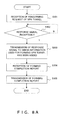
- FIGs. 7 are flowcharts explaining examples of processes of device registration.
- FIG. 7A is a flowchart explaining an example of a process of an SGW related to device registration.
- the SGW 221 checks whether or not there is a device that has been added newly or whether there is a communication device that has received changing, and determines whether or not all devices have received this check (step S101). When not all communication devices have received the check, S101 is repeated. When there is a device that has been added newly or that received changing, the SGW 221 obtains the ID information of the device (step S102 and YES in step S101).
- the GW control device 212 transmits, to the SGW 221, a response signal to which the encryption key/certificate/IP information of the VPN-GW 213 and the ID and address of the communication device 222 for which an access by the SGW 221 is desired have been added (step S303).
- the GW control device 212 receives a report of the completion of the forming of the VPN tunnel from the SGW 221 (step S304).
- the GW control device 212 transmits the report of the completion of the forming of the VPN tunnel to the management terminal 211 (step S305).
Landscapes
- Engineering & Computer Science (AREA)
- Computer Networks & Wireless Communication (AREA)
- Signal Processing (AREA)
- Computer Security & Cryptography (AREA)
- Computer Hardware Design (AREA)
- Computing Systems (AREA)
- General Engineering & Computer Science (AREA)
- Data Exchanges In Wide-Area Networks (AREA)
- Mobile Radio Communication Systems (AREA)
Abstract
Description
- The embodiments discussed herein are related to an access control method.
- Devices that can perform communications with a different device may sometimes be provided in a hub of a company. Examples of these devices are a printer, a sensor, an air conditioner, etc, all of which have communication devices. These communication devices are included in a data network protected by securities such as a firewall or the like. Accordingly, a firewall prevents direct accesses to these communication devices from an external environment.
- As a method of accessing a communication device from a remote environment, Secure Socket Layer-Virtual Private Network (SSL-VPN) is used. SSL-VPN is a technique that provides a virtual network using an SSL for encryption between hubs.
-
FIG. 1 illustrates an example of a method of accessing a hub from a management terminal by using SSL-VPN. Amanagement center 110 is provided with amanagement terminal 111 and a Virtual Private Network Gateway (VPN-GW) 120. Themanagement terminal 111 is a terminal used when devices in a hub 1 (140-1) are managed. The VPN-GW 120 is a gateway device used when ahub 140 is accessed by themanagement terminal 111 by using SSL-VPN. The network of thehub 1 is protected by afirewall 130 and includes a Service Gateway (SGW) 141, a communication device 142a, and a communication device 142b. For example, when a user attempts to access the communication device 142b directly from themanagement terminal 111, the access is blocked by thefirewall 130. In an access method using SSL-VPN for avoiding thefirewall 130, aVPN tunnel 150 is provided beforehand between the SGW 141 and the VPN-GW 120. The provision of theVPN tunnel 150 makes it possible for themanagement terminal 111 to avoid the blockage by thefirewall 130. When a user desires to access the communication device 142b, themanagement terminal 111 accesses the SGW 141 using a route through theVPN tunnel 150. Thereafter, themanagement terminal 111 accesses the communication device 142b via the SGW 141. Also, a plurality of hubs such as hub 1 (140-1) through hub 2 (140-n) may exist, and VPN tunnels 150-1 through 150-n are provided in accordance with the number of hubs. Communication devices may be servers or personal computers (PCs). - As an access method for avoiding a firewall, a technique as below is known. A first gateway operates at a low operation ratio for a client having access information for the first gateway, and an instruction that connection be made through a second gateway, which is arranged closer to the client, is transmitted. The first and second gateways exchange information with each other, and thus the client can access a particular server without performing setting changes for using the second gateway (See
Patent Document 1 for example). - Patent Document 1: Japanese National Publication of International Patent Application No.
2012-519416 - An object in one aspect of the present invention is to form a VPN tunnel in accordance with accesses to a communication terminal of the hub from the management terminal.
- According to an aspect of the embodiments, a management terminal belonging to a first network periodically receives a registration request of information of a communication terminal belonging to a second network from a gateway device belonging to the second network. A control device belonging to the first network receives a communication request that a communication path be secured between the management terminal and the communication terminal from the management terminal. The control device includes the communication request in a latest response to a registration request received from the gateway device periodically and transmits the communication request to the gateway device. The gateway device permits an access to the communication terminal from the management terminal via a tunnel formed in response to the communication request.
-
-
FIG. 1 illustrates an example of a method of accessing a hub from a management terminal by using SSL-VPN; -
FIG. 2 explains an example of a method of forming a VPN tunnel; -
FIG. 3 is a sequence diagram explaining an example of a process of a method of forming a VPN tunnel according to a first embodiment; -
FIG. 4A is a sequence diagram explaining an example of a process related to a periodic request transmitted from the SGW; -
FIG. 4B is a sequence diagram explaining an example of a process related to a periodic request transmitted from the SGW; -
FIG. 5 is a sequence diagram explaining an example of deletion of device information in a case when a communication device has been removed; -
FIG. 6 illustrates an example of a hardware configuration of a management terminal, a GW control device, a VPN-GW, and an SGW; -
FIG. 7A is a flowchart explaining an example of a process of device registration; -
FIG. 7B is a flowchart explaining an example of a process of device registration; -
FIG. 8A is a flowchart that explains an example of a process of forming a VPN tunnel; -
FIG. 8B is a flowchart that explains an example of a process of forming a VPN tunnel; -
FIG. 9A is a flowchart that explains an example of a deletion process of registered device information; -
FIG. 9B is a flowchart that explains an example of a deletion process of registered device information; -
FIG. 10A is a sequence diagram explaining an example of a process of a request signal using a GW control device; -
FIG. 10B is a sequence diagram explaining an example of a process of a request signal using a GW control device; -
FIG. 11 is a sequence diagram explaining an example of a process of a forming method of a VPN tunnel according to a second embodiment. - Hereinafter, the present embodiment will be explained by referring to the drawings.
-
FIG. 2 explains an example of a method of forming a VPN tunnel. Amanagement center 210 is a network that includes amanagement terminal 211, aGW control device 212, and a VPN-GW 213. Ahub 220 is a network that includes an SGW 221 and acommunication device 222. The processes in which a VPN tunnel is formed from the management center side and themanagement terminal 211 accesses thecommunication device 222 will be explained sequentially. - (1) The
management terminal 211 accesses the VPN-GW 213 in order to access the communication device 222 (arrow 201). - (2) When a
VPN tunnel 250 has already been formed between themanagement terminal 221 and the VPN-GW 213, themanagement terminal 211 can access thecommunication device 222 by using the VPN that has already been formed (arrow 202). - (3) When the
VPN tunnel 250 has not been formed yet, themanagement terminal 211 outputs, to theGW control device 212, a request signal including a request that theVPN tunnel 250 be formed (arrow 203). - (4) The
GW control device 212 receives a periodic request signal transmitted from the SGW 221 (arrow 204). The periodic request signal is a signal transmitted for registering, in the management center side, the information of thecommunication device 222 provided in a hub. Thereby, it is possible to obtain, on the management center side, information related to thecommunication device 222 that is provided in a hub. - (5) As a response to a received request signal, the
GW control device 212 returns, to theSGW 221, a response signal, which includes a request signal including a request that theVPN tunnel 250 be formed, an encryption key, and a certificate (arrow 205). The response signal is a signal used in response to a request signal. - (6) Having received a response signal, the
SGW 221 forms theVPN tunnel 250 between theSGW 221 and the VPN-GW 213. - (7) The
management terminal 211 can access the communication device 222 (arrow 202). - The request signal in (4) is, for example, an HTTP request. The response signal of (5) is an HTTP response to an HTTP request. When the request of (4) does not exist and a request signal requesting that the VPN tunnel of (5) be formed has been reported, a signal from the GW control device is blocked by a firewall, and it is not possible to form a VPN tunnel. Accordingly, in (5), the blockage by a firewall is avoided by adding a request that a VPN tunnel be formed to a response signal to a request signal from the
SGW 221. A VPN tunnel is formed in accordance with an access to a communication device in a hub from the management terminal by using the method of forming a VPN method as described in (1) through (7). VPN-GW 213 is a starting point of VPN tunnel is formed. -
FIG. 3 is a sequence diagram explaining an example of a process of a method of forming a VPN tunnel according to the first embodiment. The same devices as those inFIG. 2 are denoted by the same numerals. Themanagement terminal 211 accesses the VPN-GW 213 in order to access the communication device 222 (arrow 301). When a VPN tunnel has not been formed, the VPN-GW 213 reports to themanagement terminal 211 that a VPN tunnel has not been formed (arrow 302). Themanagement terminal 211 transmits to the GW control device 212 a request signal requesting that a VPN tunnel be formed (arrow 303). The request signal includes the ID and the address of thecommunication device 222 that themanagement terminal 211 desires to access. TheSGW 221 transmits a periodic request signal to the GW control device 212 (arrow 304). A periodic request signal will be described later inFIGs. 4 . TheGW control device 212 adds, to a response signal to a request signal from theSGW 221, a request that a VPN tunnel be formed and information used for forming the VPN tunnel, and reports it to the SGW 221 (arrow 305). Information used for forming a VPN tunnel includes an encryption key of the VPN-GW 213, a certificate, IP information, the ID and the address of thecommunication device 222 that themanagement terminal 211 desires to access, the ID of the GW to be formed in thecommunication device 222, or the like. Also, theGW control device 212 assigns the IP address corresponding to a Network Interface Card (NIC) on the SGW side to a VPN tunnel. TheSGW 221 uses information received from theGW control device 212, and forms a VPN tunnel between theSGW 221 and the VPN-GW 213 (arrow 306). When a VPN tunnel has been formed, theSGW 221 reports the completion of the forming to the GW control device 212 (arrow 307). TheGW control device 212 reports the formation of a VPN tunnel to the management terminal 211 (arrow 308). Themanagement terminal 211 reports a control message for manipulating thecommunication device 222 to theSGW 221 via the VPN tunnel (arrow 309). The control message includes manipulation information, an ID, and address information for controlling thecommunication device 222. TheSGW 221 performs address conversion by using schemes such as Network Address Translation (NAT) or Network Address Port Translation (NAPT), and outputs a control signal to the communication device 222 (arrow 310). Thecommunication device 222 executes a process of the received control signal, and reports the completion to the SGW 221 (arrow 311). TheSGW 221 reports the completion of the process of thecommunication device 222 to the management terminal 211 (arrow 312). In the forming method of a VPN tunnel according to the first embodiment, a VPN tunnel is formed in response to an access from the management terminal to a communication device in a hub. -
FIGs. 4 are sequence diagrams explaining an example of a process related to a periodic request transmitted from an SGW. The same members as those inFIG. 3 are denoted by the same numerals. A periodic request signal is a signal transmitted for registering, in the management center side, information of thecommunication device 222 provided in a hub. One communication device may exist or a plurality of communication devices may exist. A response signal is a registration completion signal in response to a request signal for registering a communication device.FIG. 4A is a sequence diagram for explaining an example of a process related to a periodic request. TheSGW 221 transmits to the GW control device 212 a request signal for registering, in the management center side, information related to all stored devices (arrow 401). TheGW control device 212 stores information related to a received device, and makes themanagement terminal 211 hold the ID information of the device (arrow 402). Themanagement terminal 211 reports to theSGW 221 the storage of the ID information of the device (arrow 403). TheGW control device 212 returns, to theSGW 221, the fact that the information related to the device has been stored as a response signal to a request signal (arrow 404). Themanagement terminal 211 requests, from theGW control device 212, an address corresponding to a stored device ID (arrow 405) TheGW control device 212 reports, to themanagement terminal 211, the address corresponding to the device ID (arrow 406). - The request signal denoted by
arrow 401 may be transmitted from the SGW periodically at timings that can be changed by a user. A periodic request signal is transmitted to theGW control device 212 from theSGW 221, and thereby information related to a device is registered on the management center side automatically even in an environment where IP addresses of devices are changed dynamically. Also, theSGW 221 has stored IP addresses of devices that have been changed dynamically. Because information related to a device is registered on the management center side automatically, it is not necessary for a user to know information of a device beforehand. The ID information of a device is ID information and the MAC address of the device, etc. A request signal from theSGW 221 includes the address, the ID of a device and the ID of a GW. The ID of a GW is the ID of a VPN-GW used for forming a VPN tunnel. -
FIG. 4B is a sequence diagram that explains a process related to a request signal in a case when a communication device has been added newly. When a communication device has been added newly to a hub, information related to the added device is registered in the SGW and the management center side. The SGW may detect the newly added device and the newly added device may report that it has started the participation in the network newly. When thecommunication device 222 has been added to a network, thecommunication device 222 reports, to thecommunication device 222, the ID information of a device that has been added newly to a hub (arrow 407). TheSGW 221 assigns an IP address to the newly added device, and stores information in which the ID of the newly added device and the IP address are associated. TheSGW 221 transmits to the GW control device 212 a request signal for registering device information related to all stored devices in the management center side (arrow 401) . TheGW control device 212 stores information related to the received device, and makes themanagement terminal 211 hold the ID information of the device (arrow 402). Themanagement terminal 211 reports to theSGW 221 that the ID information of the device has been stored (arrow 403). TheGW control device 212 returns, to theSGW 221, the fact that the information related to the device has been stored as a response signal to a request signal (arrow 404). Themanagement terminal 211 requests, from theGW control device 212, an address corresponding to a stored device ID (arrow 405). TheGW control device 212 reports, to themanagement terminal 211, the address corresponding to the device ID (arrow 406). TheSGW 221 reports the completion of the registration of the information related to the device to the communication device 222 (arrow 408). - It has not been possible for the management center side to recognize an addition or removal of a device on the hub side. However, by performing communications as illustrated in
FIG. 4B , information related to a device that has been added newly is registered on the management center side automatically. Also, users do not have to make inquires in order to know information of devices. -
FIG. 5 is a sequence diagram explaining an example of deletion of device information in a case when a communication device has been removed. The same members as those inFIG. 3 are denoted by the same numbers. Deletion of device information is a process for deleting device information registered at the management center side. When a device has been removed, thecommunication device 222 reports to the SGW 221 a request that device information be deleted (arrow 501). TheSGW 221 deletes the information related to the registeredcommunication device 222, and transmits, to theGW control device 212, a request signal including an instruction to delete the information related to the communication device 222 (arrow 502). TheGW control device 212 deletes information related to the registeredcommunication device 222 and transmits to theGW control device 212 an instruction to delete information related to the communication device 222 (arrow 503). Themanagement terminal 211 reports the completion of the deletion process to the GW control device 212 (arrow 504) . When a VPN tunnel has been formed as a communication path used by themanagement terminal 211 to access thecommunication device 222, theGW control device 212 reports to the VPN-GW 213 an instruction to disconnect the VPN tunnel (arrow 505). TheGW control device 212 receives from the VPN-GW 213 a report indicating the completion of the disconnection of the VPN tunnel (arrow 506). TheGW control device 212 reports the completion of the deletion to the SGW 221 (arrow 507). TheSGW 221 reports the completion of the deletion to the communication device 222 (arrow 508). - As described above, information of a device that is not to be used anymore is deleted from the
management terminal 211. In an environment where a VPN tunnel is disconnected by a time out or the like, the processes corresponding to thearrows arrow 505, when a VPN tunnel is being used for accesses with a plurality of communication devices, the GW control device outputs an instruction to disconnect a VPN tunnel when themanagement terminal 211 deletes all communication devices. When a VPN tunnel is being used for accesses with a plurality of communication devices and the management terminal deletes information related to one communication device, a VPN tunnel is not disconnected. -
FIG. 6 illustrates an example of a hardware configuration of the management terminal, the GW control device, the VPN-GW, and the SGW. Themanagement terminal 211, theGW control device 212, the VPN-GW 213, and the 221 include aprocessor 11, amemory 12, a bus 13, anexternal storage device 14, and anetwork connection device 15. Optionally, themanagement terminal 211, theGW control device 212, the VPN-GW 213, and theSGW 221 may include aninput device 16, anoutput device 17, and amedium driving device 18. Themanagement terminal 211, theGW control device 212, the VPN-GW 213, and theSGW 221 may sometimes be implemented by, for example, a computer. - The
processor 11 may be an arbitrary processing circuit that includes a Central Processing Unit (CPU). Theprocessor 11 executes respective processes that are performed by themanagement terminal 211, theGW control device 212, the VPN-GW 213, and theSGW 221. Also, theprocessor 11 may execute a program stored in for example theexternal storage device 14. Thememory 12 operates as a storage area, and stores data obtained as a result of operations of theprocessor 11 and data used for processes by theprocessor 11 on an as-needed basis. Thenetwork connection device 15 is used for performing communications with a different device, and includes atransmission unit 21 and areception unit 20 for receiving a signal. - The
input device 16 is implemented as for example a button, a keyboard, a mouse, etc., and theoutput device 17 is implemented as a display device, etc. The bus 13 connects theprocessor 11, thememory 12, theinput device 16, theoutput device 17, theexternal storage device 14, themedium driving device 18, and thenetwork connection device 15 so that data can be transmitted and received between them. Theexternal storage device 14 stores a program, data, etc., and provides stored information to theprocessor 11 or the like on an as-needed basis. Themedium driving device 18 may output data of thememory 12 and theexternal storage device 14 to atransportable storage medium 19, and may read a program, data, etc., from thestorage medium 19. In this example, thestorage medium 19 may be an arbitrary portable storage medium including a floppy disk, a Magneto-Optical (MO) disk, a Compact Disc Recordable (CD-R), or a Digital Versatile Disk Recordable (DVD-R). -
FIGs. 7 are flowcharts explaining examples of processes of device registration.FIG. 7A is a flowchart explaining an example of a process of an SGW related to device registration. TheSGW 221 checks whether or not there is a device that has been added newly or whether there is a communication device that has received changing, and determines whether or not all devices have received this check (step S101). When not all communication devices have received the check, S101 is repeated. When there is a device that has been added newly or that received changing, theSGW 221 obtains the ID information of the device (step S102 and YES in step S101). TheSGW 221 assigns an IP address to a newly-added/changed device, and stores information in which the ID of a newly-added/changed device and an IP address are associated (step S103). TheSGW 221 transmits to the GW control device 212 a request signal for registering, in the management center side, all of the stored pieces of device information related to devices (step S104). TheSGW 221 receives a response signal that reports that the information included in a request signal has been registered on the management center side (step S105). TheSGW 221 reports the completion of the registration to the communication device (step S106), and theSGW 221 terminates the process. -
FIG. 7B explains a flowchart that explains an example of a process of a GW control device related to device registration. When receiving a request signal, theGW control device 212 stores information included in the request signal (step S201; corresponds to the request signal in step S104 inFIG. 6A ). TheGW control device 212 outputs an instruction to store ID information of added/changed device in the management terminal 211 (step S202). TheGW control device 212 receives a report of the completion of the registration of the ID of the device (step S203) from themanagement terminal 211. TheGW control device 212 returns, to theSGW 221, the fact that the information related to the device has been stored as a response signal to a request signal (step S204). TheGW control device 212 receives a request signal of address information corresponding to the device ID stored in the management terminal 211 (step S205). TheGW control device 212 transmits to themanagement terminal 211 the requested address information related to the device from the management terminal 211 (step S206). In an environment where theSGW 221 does not detect an addition of a communication device, the process in step S101 is skipped. The processes related to a periodic request signal correspond to steps S104 through 105 and steps S201 through 206 inFIGs. 7 . -
FIGs. 8 are flowcharts that explain examples of processes of forming a VPN tunnel.FIG. 8A is a flowchart that explains an example of a process performed by a GW control device related to the forming of a VPN tunnel. TheGW control device 212 receives from the management terminal 211 a request signal that requests that a VPN tunnel be formed (step S301). TheGW control device 212 determines whether or not a request signal has been received from an SGW (step S302). When a request signal has not been received, S302 is repeated. TheGW control device 212 transmits, to theSGW 221, a response signal to which the encryption key/certificate/IP information of the VPN-GW 213 and the ID and address of thecommunication device 222 for which an access by theSGW 221 is desired have been added (step S303). TheGW control device 212 receives a report of the completion of the forming of the VPN tunnel from the SGW 221 (step S304). TheGW control device 212 transmits the report of the completion of the forming of the VPN tunnel to the management terminal 211 (step S305). -
FIG. 8B is a flowchart that explains an example of a process, by an SGW, related to the forming of a VPN tunnel. TheSGW 221 transmits a periodic request signal to the GW control device 212 (step S401). TheSGW 221 receives a response signal corresponding to a request signal (step S402). TheSGW 221 determines whether or not a response signal includes a request that a VPN tunnel be formed (step S403). TheSGW 221 forms a VPN tunnel between theSGW 221 and the VPN-GW 213 by using information such as the encryption key, the certificate, and the GW-ID received from the GW control device 212 (step S404 and YES in step S403). TheSGW 221 reports the completion of the forming of the VPN tunnel to the GW control device 212 (step S405). TheSGW 221 waits for a prescribed period of time (step S406 and NO in step S403). TheSGW 221 repeats the processes from step S401 after waiting for a prescribed period of time. -
FIGs. 9 are flowcharts that explain an example of a deletion process of registered device information.FIG. 9A is a flowchart that explains an example of a process, by an SGW, related to the deletion of registered device information. TheSGW 221 receives from the communication device 222 a deletion request and the ID information of the device to be deleted (step S501). TheSGW 221 deletes information related to thecommunication device 222 that has been registered (step S502) . TheSGW 221 reports to the GW control device 212 a deletion instruction and the ID information of the device to be deleted (Step S503). TheSGW 221 receives a report of the completion of the deletion process from the GW control device 212 (step S504). TheSGW 221 reports the completion of the deletion process to the communication device 222 (step S505). TheSGW 221 terminates the process. -
FIG. 9B is a flowchart that explains an example of a process, by a GW control device, related to the deletion of registered device information. TheGW control device 212 receives, from theSGW 221, a deletion instruction and the ID information of a deletion target device (step S601). TheGW control device 212 deletes information related to thecommunication device 222 that has been registered (step S602). TheGW control device 212 transmits to themanagement terminal 211 an instruction to delete information related to the communication device 222 (step S603). TheGW control device 212 receives information indicating the completion of the deletion process from the management terminal 211 (step S604). TheGW control device 212 determines whether or not all pieces of information related to a device in a hub in which theSGW 221 is arranged are to be deleted (step S605). When all pieces of information related to a device in a hub are to be deleted, theGW control device 212 makes the VPN-GW 213 disconnect the VPN tunnel (step S606 and YES in step S605). TheGW control device 212 receives from the VPN-GW 213 a report that a VPN tunnel has been disconnected (step S607). TheGW control device 212 reports the completion of the deletion process to the SGW 221 (step S608 and NO in step S605). TheGW control device 212 terminates the process. - As described above, in the methods according to the embodiments, a VPN tunnel is formed in accordance with an access to a communication device in a hub from a management terminal. Also, information on a device that has been added/removed in a hub is reported to the management side and is registered.
- Also, the embodiments are not limited to the above, and various modifications are allowed. Examples thereof will be described below.
- The management terminal, the GW control device, and the VPN-GW may form an integrated environment by using a virtual server. In
FIG. 10 andFIG. 11 , a device that obtained by integrating the management terminal, the GW control device, and the VPN-GW is simply referred to as a GW control device. -
FIGs. 10 are sequence diagrams explaining an example of a process that uses a control device and that is related to a request.FIG. 10A is a sequence diagram for explaining an example of a process of a request signal in the addition of a device. When acommunication device 601 has participated in a network, thecommunication device 601 reports, to anSGW 602, the ID information of the device that has been newly added to a hub (arrow 701). TheSGW 602 assigns an IP address to the newly added device, and stores information in which the ID of the added device and the IP address are associated. TheSGW 602 transmits to a GW control device 603 a request signal for registering device information related to all stored devices on the management center side (arrow 702). TheGW control device 603 stores the received information related to the device, and returns to theSGW 602 the fact that the information related to the device has been stored (arrow 703). TheSGW 602 reports the completion of the registration of the information related to the device (arrow 704). -
FIG. 10B is a sequence diagram explaining an example of a process of a request signal for adding a device from the SGW. In an environment where the SGW detects a device that has been newly added, the SGW may assign an ID and an IP address to a communication device. When theSGW 602 has detected that thecommunication device 601 participated in a network, theSGW 602 assigns an ID and an address to thecommunication device 601. TheSGW 602 reports to thecommunication device 601 the ID that has been assigned to the communication device 601 (arrow 705) . Thecommunication device 601 stores the reported ID, and returns to theSGW 602 the fact that the ID has been stored (arrow 706) . TheSGW 602 transmits, to theGW control device 603, a request signal for registering, on the management center side, all pieces of device information related to stored devices (arrow 707). TheGW control device 603 stores the received information that is related to a device, and returns, to theSGW 602 and as a response signal to the request signal, the fact that the information related to the device has been stored (arrow 708) . -
FIG. 11 is a sequence diagram explaining an example of a process of a forming method of a VPN tunnel according to a second embodiment. The same members as those inFIG. 9 are denoted by the same numerals. TheSGW 602 transmits a periodic request signal to the GW control device 603 (arrow 801). When there is a request that a communication path to theSGW 602 be secured, theGW control device 603 adds to a response signal to a sequential signal from theSGW 602 the request that a VPN tunnel be formed and information used for forming a VPN tunnel, and reports the signal to the SGW 602 (arrow 802). The communication request is instructed to be given as a result of, for example, manipulations by a user. Information used for forming a VPN tunnel includes an encryption key, a certificate, IP information, an ID/address of a communication device to be accessed, the ID of the GW, etc. TheSGW 602 uses information received from theGW control device 603 so as to form a VPN tunnel between theSGW 602 and the GW control device 603 (arrow 803). When a VPN tunnel has been formed, theSGW 602 reports the completion of the forming to the GW control device 603 (arrow 804). TheGW control device 603 reports, to theSGW 602 and via the VPN tunnel, a control message for manipulating the communication device 601 (arrow 805). TheSGW 602 performs address conversion by using schemes such as NAT, NAPT, etc., and outputs a control signal to the communication device 601 (arrow 806). Thecommunication device 601 executes the process of the received control signal, and reports the completion to the SGW 602 (arrow 807). TheSGW 602 reports the completion of the process by the 601 to the GW control device 603 (arrow 808). Also in the forming method of a VPN tunnel according to the second embodiment, a user can form a VPN tunnel in accordance with an access to a communication device in a hub from the GW control device.
Claims (8)
- An access control method that controls an access between a first network (210) and a second network (220), the method comprising:periodically receiving by a management terminal(211) belonging to the first network (210), a registration request of information related to a communication terminal (222) belonging to the second network (220) from a gateway device (221) belonging to the second network (220),including by a control device (212) belonging to the first network (210), a communication request that a communication path be secured between the management terminal(211) and the communication terminal(222) in a latest response to a registration request received from the gateway device(221) periodically when a communication request that a communication path be secured between the management terminal(211) and the communication terminal(222) has been received from the management terminal(211), and transmitting the communication request to the gateway device(221), andpermitting by the gateway device(221) an access to the communication terminal (222) from the management terminal (211) via a tunnel formed in response to the communication request.
- The access control method according to claim 1, further comprising:receiving, by the control device(212), the registration request including identification information of the communication terminal(222) reported at prescribed time intervals; andreporting, by the control device (212) to the management terminal(211), information of all of the communication terminals(222) belonging to the second network (220) by reporting the identification information to the management terminal (211).
- The access control method according to claim 1 or 2, further comprising:selecting by the control device (212), an encryption key and certificate data used for forming the tunnel when the registration request has been received; andgenerating by the control device(212), the response message in which a forming request of the tunnel including the selected encryption key and certification data.
- An access control system that controls an access between a first network(210) and a second network (220), comprising:a communication terminal (222) that belongs to the second network (220) ;a gateway device(221) that belongs to the second network (220);a management terminal(211) that belongs to the first network (210) and that periodically receives, from the gateway device (221), a registration request of information related to the communication terminal(222); anda control device(212) that belongs to the first network (210), wherein:the control device (212) includes a communication request that a communication path be secured between the management terminal(211) and the communication terminal(222) in a latest response to a registration request received from the gateway device(221) periodically when a communication request that a communication path be secured between the management terminal(211) and the communication terminal(222) has been received from the management terminal (211), and transmits the communication request to the gateway device(221), andthe gateway device(221) permits an access to the communication terminal (222) from the management terminal (211) via a tunnel formed in response to the communication request.
- The access control system according to claim 4, wherein:the control device(212) receives the registration request including identification information of the communication terminal(222) reported at prescribed time intervals; andthe control device (212) reports, to the management terminal(211), information of all of the communication terminals(222) belonging to the second network (220) by reporting the identification information to the management terminal (211).
- The access control system according to claim 4, wherein:the control device(212):selects an encryption key and certificate data used for forming the tunnel when the registration request has been received; andgenerates the response message in which a forming request of the tunnel includes the selected encryption key and certification data.
- An access control device(212) that controls an access between a first network(210) and a second network (220), comprising:a processor configured to execute a process related to the access control, wherein:the processor:receives, from the management terminal(211), a communication request that a communication path be secured between a management terminal(211) belonging to the first network(210) and a communication terminal (222) belonging to the second network (220);includes the communication request in a latest response that corresponds to a registration request of information related to the communication terminal(222) periodically transmitted to the management terminal (211) from a gateway device (221) belonging to the second network (220), and transmits the communication request to the gateway device (221); andmakes the gateway device(221) permit an access to the communication terminal(222) from the management terminal(211) via a tunnel formed in response to the communication request.
- The access control device(212) according to claim 7, wherein:the control device(212):selects an encryption key and certificate data used for forming the tunnel when the registration request has been received; andgenerates the response message in which a forming request of the tunnel includes the selected encryption key and certification data.
Applications Claiming Priority (1)
| Application Number | Priority Date | Filing Date | Title |
|---|---|---|---|
| JP2013166779A JP6229368B2 (en) | 2013-08-09 | 2013-08-09 | Access control method, access control system, and access control apparatus |
Publications (2)
| Publication Number | Publication Date |
|---|---|
| EP2835950A2 true EP2835950A2 (en) | 2015-02-11 |
| EP2835950A3 EP2835950A3 (en) | 2015-03-25 |
Family
ID=51453568
Family Applications (1)
| Application Number | Title | Priority Date | Filing Date |
|---|---|---|---|
| EP20140179652 Withdrawn EP2835950A3 (en) | 2013-08-09 | 2014-08-04 | Access control method, access control system and access control device |
Country Status (3)
| Country | Link |
|---|---|
| US (1) | US20150047009A1 (en) |
| EP (1) | EP2835950A3 (en) |
| JP (1) | JP6229368B2 (en) |
Families Citing this family (4)
| Publication number | Priority date | Publication date | Assignee | Title |
|---|---|---|---|---|
| JP6568002B2 (en) * | 2016-03-29 | 2019-08-28 | エヌ・ティ・ティ・コミュニケーションズ株式会社 | Communication system and communication method |
| JP6841128B2 (en) * | 2017-03-30 | 2021-03-10 | ブラザー工業株式会社 | Servers and computer programs for servers |
| KR102455515B1 (en) * | 2018-05-09 | 2022-10-14 | 주식회사 케이티 | Security System and Method for Home Network Access |
| EP4024667A4 (en) * | 2019-08-26 | 2023-09-27 | Nidec Corporation | Interior permanent magnet motor |
Citations (1)
| Publication number | Priority date | Publication date | Assignee | Title |
|---|---|---|---|---|
| JP2012519416A (en) | 2009-02-26 | 2012-08-23 | マイクロソフト コーポレーション | Redirect secure data connection requests |
Family Cites Families (19)
| Publication number | Priority date | Publication date | Assignee | Title |
|---|---|---|---|---|
| JP4104799B2 (en) * | 1999-11-25 | 2008-06-18 | 株式会社山武 | Network system and communication method |
| US7099957B2 (en) * | 2001-08-23 | 2006-08-29 | The Directtv Group, Inc. | Domain name system resolution |
| KR100485769B1 (en) * | 2002-05-14 | 2005-04-28 | 삼성전자주식회사 | Apparatus and method for offering connection between network devices located in different home networks |
| US20040255037A1 (en) * | 2002-11-27 | 2004-12-16 | Corvari Lawrence J. | System and method for authentication and security in a communication system |
| US7260841B2 (en) * | 2003-02-27 | 2007-08-21 | Nortel Networks Limited | System and method for maintaining access to content in an encrypted network environment |
| CN102355355B (en) * | 2003-06-19 | 2014-07-16 | 日本电信电话株式会社 | Session control server, communication device, communication system and communication method |
| JP2006277752A (en) * | 2006-04-10 | 2006-10-12 | Horizon Digital Enterprise Inc | Computer remote-managing method |
| JP4916227B2 (en) * | 2006-06-14 | 2012-04-11 | キヤノン株式会社 | Device management apparatus and control method of the management apparatus |
| US20080076425A1 (en) * | 2006-09-22 | 2008-03-27 | Amit Khetawat | Method and apparatus for resource management |
| US20100272115A1 (en) * | 2009-04-22 | 2010-10-28 | Rajesh Ramankutty | Gateway-based management in a communication network |
| KR101215191B1 (en) * | 2009-09-18 | 2012-12-24 | 엔이씨 유럽 리미티드 | communication system and communication control method |
| EP2676420A4 (en) * | 2011-02-15 | 2017-06-28 | ZTE Corporation | Internet protocol mapping resolution in fixed mobile convergence networks |
| JP5673216B2 (en) * | 2011-03-01 | 2015-02-18 | 株式会社リコー | Communication control device, communication control system, and communication control program |
| TW201246879A (en) * | 2011-04-13 | 2012-11-16 | Interdigital Patent Holdings | Methods, systems and apparatus for managing and/or enforcing policies for managing internet protocol (''IP'') traffic among multiple accesses of a network |
| WO2012147270A1 (en) * | 2011-04-28 | 2012-11-01 | Panasonic Corporation | Communication system, mobile terminal, router, and mobility management entity |
| US20140341109A1 (en) * | 2011-06-02 | 2014-11-20 | Interdigital Patent Holdings, Inc. | Methods, Apparatus and Systems for Managing Converged Gateway Communications |
| US9332426B2 (en) * | 2011-09-30 | 2016-05-03 | Nec Corporation | Communication system, communication method, and communication program |
| US9143529B2 (en) * | 2011-10-11 | 2015-09-22 | Citrix Systems, Inc. | Modifying pre-existing mobile applications to implement enterprise security policies |
| US9788188B2 (en) * | 2012-12-14 | 2017-10-10 | Ibasis, Inc. | Method and system for hub breakout roaming |
-
2013
- 2013-08-09 JP JP2013166779A patent/JP6229368B2/en active Active
-
2014
- 2014-03-21 US US14/221,705 patent/US20150047009A1/en not_active Abandoned
- 2014-08-04 EP EP20140179652 patent/EP2835950A3/en not_active Withdrawn
Patent Citations (1)
| Publication number | Priority date | Publication date | Assignee | Title |
|---|---|---|---|---|
| JP2012519416A (en) | 2009-02-26 | 2012-08-23 | マイクロソフト コーポレーション | Redirect secure data connection requests |
Also Published As
| Publication number | Publication date |
|---|---|
| US20150047009A1 (en) | 2015-02-12 |
| EP2835950A3 (en) | 2015-03-25 |
| JP2015035771A (en) | 2015-02-19 |
| JP6229368B2 (en) | 2017-11-15 |
Similar Documents
| Publication | Publication Date | Title |
|---|---|---|
| EP3739826B1 (en) | Communication method, system and apparatus | |
| JP2022020946A (en) | Information processing device, information processing system, communication format determination method, and program | |
| EP1998506A1 (en) | Virtual network connection apparatus, system, method for controlling connection of a virtual network and program | |
| US10187356B2 (en) | Connectivity between cloud-hosted systems and on-premises enterprise resources | |
| US20110277028A1 (en) | Assigning a network address for a virtual device to virtually extend the functionality of a network device | |
| EP3163833B1 (en) | Virtual private network realization method and client device | |
| KR20150013860A (en) | Clientless cloud computing | |
| EP2223549B1 (en) | Enabling provider network inter-working with mobile access | |
| EP2835950A2 (en) | Access control method, access control system and access control device | |
| CN110971434B (en) | Method, device and system for managing intranet network equipment | |
| JP2017208797A (en) | Unified data networking across heterogeneous networks | |
| US8873569B2 (en) | User centric virtual network and method of establishing the same | |
| US9473401B2 (en) | Network separation method and network separation device | |
| US20110276673A1 (en) | Virtually extending the functionality of a network device | |
| JP2017011487A (en) | Information processing system, control program of information processing system and method for controlling information processing system | |
| JP2011188448A (en) | Gateway apparatus, communication method and communication program | |
| KR101378313B1 (en) | Method, appratus, system and computer-readable recording medium for assisting communication between terminal and local host by using openflow | |
| JP6200033B2 (en) | Relay device, relay method, and relay program | |
| JP6813110B1 (en) | Communication devices, programs, communication methods, and communication systems | |
| US10021067B2 (en) | Internet protocol address distribution for wireless network | |
| JP5937708B1 (en) | COMMUNICATION CONTROL DEVICE, COMMUNICATION CONTROL METHOD, AND COMMUNICATION CONTROL PROGRAM | |
| KR20030088253A (en) | Remote computer connection and management system by using a personal terminal based on peer to peer protocol and the method thereof | |
| EP3176986A1 (en) | Method, device and system for remote desktop protocol gateway to conduct routing and switching | |
| CN107979657B (en) | DNS address processing method and system for network equipment | |
| JP6426118B2 (en) | Relay apparatus, relay method and relay program |
Legal Events
| Date | Code | Title | Description |
|---|---|---|---|
| PUAI | Public reference made under article 153(3) epc to a published international application that has entered the european phase |
Free format text: ORIGINAL CODE: 0009012 |
|
| 17P | Request for examination filed |
Effective date: 20140804 |
|
| AK | Designated contracting states |
Kind code of ref document: A2 Designated state(s): AL AT BE BG CH CY CZ DE DK EE ES FI FR GB GR HR HU IE IS IT LI LT LU LV MC MK MT NL NO PL PT RO RS SE SI SK SM TR |
|
| AX | Request for extension of the european patent |
Extension state: BA ME |
|
| PUAL | Search report despatched |
Free format text: ORIGINAL CODE: 0009013 |
|
| AK | Designated contracting states |
Kind code of ref document: A3 Designated state(s): AL AT BE BG CH CY CZ DE DK EE ES FI FR GB GR HR HU IE IS IT LI LT LU LV MC MK MT NL NO PL PT RO RS SE SI SK SM TR |
|
| AX | Request for extension of the european patent |
Extension state: BA ME |
|
| RIC1 | Information provided on ipc code assigned before grant |
Ipc: H04L 12/46 20060101ALI20150219BHEP Ipc: H04L 29/06 20060101AFI20150219BHEP |
|
| R17P | Request for examination filed (corrected) |
Effective date: 20150911 |
|
| RBV | Designated contracting states (corrected) |
Designated state(s): AL AT BE BG CH CY CZ DE DK EE ES FI FR GB GR HR HU IE IS IT LI LT LU LV MC MK MT NL NO PL PT RO RS SE SI SK SM TR |
|
| GRAP | Despatch of communication of intention to grant a patent |
Free format text: ORIGINAL CODE: EPIDOSNIGR1 |
|
| INTG | Intention to grant announced |
Effective date: 20181207 |
|
| STAA | Information on the status of an ep patent application or granted ep patent |
Free format text: STATUS: THE APPLICATION IS DEEMED TO BE WITHDRAWN |
|
| 18D | Application deemed to be withdrawn |
Effective date: 20190418 |