EP2835663A1 - Apparatuses and method for determining communication activities of a network node in different spatial directions - Google Patents
Apparatuses and method for determining communication activities of a network node in different spatial directions Download PDFInfo
- Publication number
- EP2835663A1 EP2835663A1 EP20130179477 EP13179477A EP2835663A1 EP 2835663 A1 EP2835663 A1 EP 2835663A1 EP 20130179477 EP20130179477 EP 20130179477 EP 13179477 A EP13179477 A EP 13179477A EP 2835663 A1 EP2835663 A1 EP 2835663A1
- Authority
- EP
- European Patent Office
- Prior art keywords
- network node
- network
- node
- communication activities
- error rate
- Prior art date
- Legal status (The legal status is an assumption and is not a legal conclusion. Google has not performed a legal analysis and makes no representation as to the accuracy of the status listed.)
- Ceased
Links
Images


Classifications
-
- H—ELECTRICITY
- H04—ELECTRIC COMMUNICATION TECHNIQUE
- H04W—WIRELESS COMMUNICATION NETWORKS
- H04W64/00—Locating users or terminals or network equipment for network management purposes, e.g. mobility management
- H04W64/003—Locating users or terminals or network equipment for network management purposes, e.g. mobility management locating network equipment
-
- H—ELECTRICITY
- H04—ELECTRIC COMMUNICATION TECHNIQUE
- H04W—WIRELESS COMMUNICATION NETWORKS
- H04W4/00—Services specially adapted for wireless communication networks; Facilities therefor
- H04W4/02—Services making use of location information
- H04W4/025—Services making use of location information using location based information parameters
- H04W4/026—Services making use of location information using location based information parameters using orientation information, e.g. compass
-
- G—PHYSICS
- G01—MEASURING; TESTING
- G01S—RADIO DIRECTION-FINDING; RADIO NAVIGATION; DETERMINING DISTANCE OR VELOCITY BY USE OF RADIO WAVES; LOCATING OR PRESENCE-DETECTING BY USE OF THE REFLECTION OR RERADIATION OF RADIO WAVES; ANALOGOUS ARRANGEMENTS USING OTHER WAVES
- G01S3/00—Direction-finders for determining the direction from which infrasonic, sonic, ultrasonic, or electromagnetic waves, or particle emission, not having a directional significance, are being received
- G01S3/02—Direction-finders for determining the direction from which infrasonic, sonic, ultrasonic, or electromagnetic waves, or particle emission, not having a directional significance, are being received using radio waves
- G01S3/14—Systems for determining direction or deviation from predetermined direction
- G01S3/28—Systems for determining direction or deviation from predetermined direction using amplitude comparison of signals derived simultaneously from receiving antennas or antenna systems having differently-oriented directivity characteristics
- G01S3/30—Systems for determining direction or deviation from predetermined direction using amplitude comparison of signals derived simultaneously from receiving antennas or antenna systems having differently-oriented directivity characteristics derived directly from separate directional systems
-
- G—PHYSICS
- G01—MEASURING; TESTING
- G01S—RADIO DIRECTION-FINDING; RADIO NAVIGATION; DETERMINING DISTANCE OR VELOCITY BY USE OF RADIO WAVES; LOCATING OR PRESENCE-DETECTING BY USE OF THE REFLECTION OR RERADIATION OF RADIO WAVES; ANALOGOUS ARRANGEMENTS USING OTHER WAVES
- G01S3/00—Direction-finders for determining the direction from which infrasonic, sonic, ultrasonic, or electromagnetic waves, or particle emission, not having a directional significance, are being received
- G01S3/02—Direction-finders for determining the direction from which infrasonic, sonic, ultrasonic, or electromagnetic waves, or particle emission, not having a directional significance, are being received using radio waves
- G01S3/14—Systems for determining direction or deviation from predetermined direction
- G01S3/46—Systems for determining direction or deviation from predetermined direction using antennas spaced apart and measuring phase or time difference between signals therefrom, i.e. path-difference systems
-
- H—ELECTRICITY
- H04—ELECTRIC COMMUNICATION TECHNIQUE
- H04W—WIRELESS COMMUNICATION NETWORKS
- H04W24/00—Supervisory, monitoring or testing arrangements
- H04W24/08—Testing, supervising or monitoring using real traffic
-
- H—ELECTRICITY
- H04—ELECTRIC COMMUNICATION TECHNIQUE
- H04W—WIRELESS COMMUNICATION NETWORKS
- H04W84/00—Network topologies
- H04W84/18—Self-organising networks, e.g. ad-hoc networks or sensor networks
Definitions
- the present disclosure relates to wireless sensor networks.
- the present disclosure relates to a network node for use in a wireless sensor network, a wireless sensor network comprising a plurality of network nodes, and a method for facilitating positioning of a network node in a wireless sensor network.
- WSN wireless sensor network
- network nodes for example sensors and/or routers
- this task is carried out by expert installation personnel.
- the task of determining a suitable position for a WSN node is performed by skilled personnel using special installation equipment.
- Sensor nodes may be connected in networks having different network topologies, for example a star topology, a tree topology or a mesh topology.
- the route via which a message may travel depends strongly on what type of topology is used. For example, in a network based on a star topology, network nodes will always communicate through a central node. In contrast, in a network based on a tree topology or a mesh topology, the messages may take different routes to a destination without necessarily passing through a central node.
- a network may change its routing such that some routes become heavily used.
- the location of a node in a network has an effect on the behavior of the network.
- the routing algorithms of the network may choose a path with higher latency based on the relative location of the nodes in the network, which in turn may affect the network application.
- Such changes in the message routes may arise due to changes in the building situation over time. For example, some walls may have been added or removed in order to create different rooms. Furthermore, shifting around furniture may affect the signal propagation in the environment, which may lead to a changed route. In addition to changes in the building structure, the presence of people and electromagnetic interferers may also affect the network.
- Installing a WSN in a commercial building or a home may involve measuring the signal strength in the environment and, based on these measurements, placing the WSN nodes in optimal locations. These locations could be optimal with respect to network coverage, message latency and/or node power usage.
- signal strength measurements as used in conventional WSN installation procedures only provide a static view of the RF conditions in a building or a home. In other words, the view is inherently limited to the RF conditions measured at the time of installation of the WSN. If in the case of a change in the environment the WSN does not work properly, then the experts have to be hired again to perform new signal strength measurements, which is costly and still does not represent a dynamic solution.
- a network node for use in a wireless sensor network, said network node being arranged to determine communication activities of the network node in different spatial directions extending from the network node, and said network node comprising at least one visual indicator being arranged to provide a visual indication of said communication activities.
- the network node is arranged to determine said communication activities by measuring differences in the strength and/or phase of a signal received by different antennas comprised in or attached to said network node.
- At least one of the antennas is detachable from the network node.
- the network node is arranged to determine said communication activities by receiving messages from other network nodes, extracting coordinates of the other network nodes from said messages, and using said coordinates to determine the spatial directions from which said messages have been sent.
- the network node is arranged to generate said visual indication in dependence on its spatial orientation.
- the spatial orientation of the network node is pre-set.
- the network node further comprises a compass which is arranged to determine the spatial orientation of the network node.
- said visual indicator comprises a plurality of light-emitting diodes.
- said visual indicator comprises a display unit.
- the display unit comprises electronic ink.
- the network node further comprises a processing element which is arranged to execute an algorithm that maintains a history of message reception and to use said history for determining the communication activities.
- the network node is further arranged to provide a network quality indication based on an error rate of received messages.
- the error rate is one of the group consisting of a bit error rate, a packet error rate and a message error rate.
- a wireless sensor network comprising a plurality of network nodes, at least one network node being of the kind set forth.
- a method for facilitating positioning of a network node in a wireless sensor network, wherein said network node determines communication activities of the network node in different spatial directions extending from the network node, and wherein said network node comprises at least one visual indicator which provides a visual indication of said communication activities.
- a network node for use in a wireless sensor network, said network node being arranged to determine communication activities of the network node in different spatial directions extending from the network node, and said network node comprising at least one visual indicator being arranged to provide a visual indication of said communication activities.
- a dynamic view of the RF conditions in the wireless sensor network may be provided to a user.
- a more intuitive installation of a WSN is enabled by visualizing network traffic routing on individual network nodes through visual indicators, for example light-emitting diodes, that show how a particular network node communicates with neighboring network nodes.
- visual indicators for example light-emitting diodes
- a user is able to see, by means of a visual indication, the extent to which a particular node communicates properly in the network, without the need for specialized instruments or expert skills. This facilitates determining the location where network nodes have to be placed in a building for optimal functioning of the network.
- the node may measure the amount and quality of traffic between itself and its neighbors through signal strength and/or phase differences between different signals received by respective antennas of the node, and activate the visual indicators based on this information, in order to provide the user with an indication as to whether the node is performing well in the network at the current location.
- signal strength as used herein may refer to various well-known characteristics of a signal, such as its amplitude and signal-to-noise ratio.
- the node is equipped with a compass so that it may determine its orientation in space.
- the node is provided with location data representing the node's coordinates within the building, for example during a so-called commissioning operation at the time of its installation.
- the node sends its coordinates, which may for instance be Cartesian coordinates (x, y, z), in messages to other nodes, such that a receiving node may determine the direction from which a message was sent using its own coordinates and the coordinates of the sending node, and generate a visual indication based on said direction.
- the receiving node may take its spatial orientation with respect to 'North' into account when generating said visual indication. For example, the node may use its spatial orientation in order to determine which of a plurality of visual indicators has to be activated.
- Fig. 1 shows an illustrative embodiment of a network node.
- the network node 100 comprises a processing element 102 which contains at least a central processing unit (CPU) and a memory unit.
- the processing element 102 may execute a computer program stored in the memory unit, for example, or fixed logic in hardware.
- the network node 100 comprises a sensor 104, i.e. a sensing element able to sense a physical quantity, such as temperature, pressure, etc.
- the network node 100 comprises a plurality of visual indicators 106, 108, 110, 112 and an array of three antennas 114, 116, 118 that are placed at half a wavelength apart. This wavelength corresponds to the frequency at which the network operates.
- the network node 100 may have an arbitrary orientation in space with respect to North. Furthermore, the network node 100 may have an arbitrary height relative to the floor level.
- the network node 100 When the network node 100 is placed in a network with other similar types of nodes, then it may have neighbors in the directions North (N), South (S), East (E) and (W) West. Thus, the network node 100 will receive messages from these different directions.
- the network node 100 may determine the direction from which a message is received by comparing, for example, the phase of the signals received by the three antennas 114, 116, 118, and/or the strength of the signals received by the three antennas 114, 116, 118. The differences between the strength and/or phase of the signals received by the respective antennas 114, 116, 118 thus form the basis to calculate the direction from which signals are received.
- At least one of the antennas may be detachable from the network node, such that the antennas may be set, at least temporarily, further apart from each other. This, in turn, increases the reliability of the determination of said direction, in that the differences between the strength of the received signals are likely to be more significant.
- the network node 100 may have an array of visual indicators 106, 108, 110, 112, each of which comprises light-emitting diodes (LEDs) of different colors, for example red, green and yellow, facing each of the four directions, namely, North, South, East and West.
- the programmed logic in the network node 100 may, for example, turn on a green LED in a direction from where a message is received and a red LED from a direction from which no message is received. In this way, a user may look at the color of the lit LEDs and immediately see in which direction the network node 100 is communicating. It is also possible to indicate more precise directions such as North-East and North-Northeast by means of multiple LEDs on the network node 100, emitting different colors and intensity of light.
- E-ink display units are particularly suitable for very power-constrained nodes.
- additional network information may also be displayed to the user.
- a node with a circular casing may have a much larger number of visual indicators around its perimeter.
- an algorithm in the processing element 102 or in hardware maintains and uses a history of message reception to determine which LEDs have to be lit. For example, it is possible that when more than 80% of messages are received from the North direction, then the green LED could be lit in that direction and other directions could show either yellow or red LEDs depending on the relative amount of messages received from that particular direction.
- This embodiment enables a more reliable indication of the communication activities of the node. For example, it takes into account the node's communication with nodes that are temporarily inactive. Temporarily inactive nodes may send many messages to the node when they are active; therefore they may still contribute significantly to the node's communication activities over time.
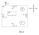
- Fig. 2 shows another illustrative embodiment of a network node.
- the network node 200 comprises only one antenna 114 and a compass 202.
- the other components of the network node 100 are the same as the components shown in Fig. 1 .
- the network node 200 is equipped with the compass 202 so that it may determine its orientation with respect to the direction North. The latter facilitates generating the visual indication, for example it facilitates determining which subset of visual indicators 106, 108, 110, 112 has to be lit in order to indicate a communication activity in a certain spatial direction.
- the orientation of the network node 200 may be pre-set, for example the network node 200 may be aligned with North. In that case, orientation data indicative of the node's pre-set orientation in space may be stored in the node and the compass 202 may be omitted.
- the network node 200 is made aware of its Cartesian coordinates (x, y, z) on the building floor plan, and these coordinates (location data) may be stored in the network node 200.
- Cartesian coordinates x, y, z
- location data location data
- a method may be used as described in the European patent application titled "Localization Method, Computer Program Product and Localization Device", filed by applicant NXP B.V. on 5 December 2011 and published as EP 2 602 677 A1 on 12 June 2013 .
- the z-dimension may also be relevant because the network nodes may be positioned at different heights in a building, for example.
- network nodes when communicating, may then include their Cartesian coordinates (x, y, z) in outgoing messages, such that a receiving node may determine the direction where a particular message came from and provide a corresponding visual indication. Also, the amount and quality of traffic, for example as represented by the number of correctly received messages by the node, may be used to provide the visual indication.
- Fig. 3 shows an illustrative embodiment of a wireless sensor network.
- a network comprising four instances of network nodes 200 within a building perimeter 300.
- Each of these network nodes 200 have been commissioned with coordinates on the floor plan of a building.
- These network nodes 200 communicate in a special mode of operation at the time of installation or network monitoring, they put their coordinates x, y and z within the building in outgoing messages.
- a receiving node may then use the data from the received message (x, y and z) and calculate the relative position of the sending node with respect to its own position. This node can then give an indication about the direction from which it received the message using its visual indicator.
- a sending node may put its unique identifier (ID) in its outgoing messages, such that a display unit on a receiving node may display information about the sending node to the user.
- ID unique identifier
Landscapes
- Engineering & Computer Science (AREA)
- Computer Networks & Wireless Communication (AREA)
- Signal Processing (AREA)
- Physics & Mathematics (AREA)
- General Physics & Mathematics (AREA)
- Radar, Positioning & Navigation (AREA)
- Remote Sensing (AREA)
- Mobile Radio Communication Systems (AREA)
Abstract
Description
- The present disclosure relates to wireless sensor networks. In particular, the present disclosure relates to a network node for use in a wireless sensor network, a wireless sensor network comprising a plurality of network nodes, and a method for facilitating positioning of a network node in a wireless sensor network.
- Typically, the installation of a wireless sensor network (WSN) requires the placement of network nodes, for example sensors and/or routers, in optimal locations in an environment, such as a building or a home. Usually this task is carried out by expert installation personnel. The task of determining a suitable position for a WSN node is performed by skilled personnel using special installation equipment.
- Sensor nodes may be connected in networks having different network topologies, for example a star topology, a tree topology or a mesh topology. The route via which a message may travel depends strongly on what type of topology is used. For example, in a network based on a star topology, network nodes will always communicate through a central node. In contrast, in a network based on a tree topology or a mesh topology, the messages may take different routes to a destination without necessarily passing through a central node.
- In topologies in which messages can take different routes, a network may change its routing such that some routes become heavily used. In such networks, the location of a node in a network has an effect on the behavior of the network. For example, the routing algorithms of the network may choose a path with higher latency based on the relative location of the nodes in the network, which in turn may affect the network application.
- Such changes in the message routes may arise due to changes in the building situation over time. For example, some walls may have been added or removed in order to create different rooms. Furthermore, shifting around furniture may affect the signal propagation in the environment, which may lead to a changed route. In addition to changes in the building structure, the presence of people and electromagnetic interferers may also affect the network.
- Installing a WSN in a commercial building or a home may involve measuring the signal strength in the environment and, based on these measurements, placing the WSN nodes in optimal locations. These locations could be optimal with respect to network coverage, message latency and/or node power usage.
- When home owners want to install a WSN, they generally do not have access to special installation tools. Furthermore, the methods described in installation instructions for a WSN are usually not intuitive and difficult to follow for unskilled individuals. In home environments, this way of working would require that experts be hired, which would lead to higher costs for a WSN installation.
- Even when the networks are designed and installed by experts on the basis of conventional signal strength measurements, dynamic effects - such as changes to a building, movement of furniture, intermittent RF disturbances (e.g. Wi-Fi) and people moving around - will not generally be taken into account. Thus, signal strength measurements as used in conventional WSN installation procedures only provide a static view of the RF conditions in a building or a home. In other words, the view is inherently limited to the RF conditions measured at the time of installation of the WSN. If in the case of a change in the environment the WSN does not work properly, then the experts have to be hired again to perform new signal strength measurements, which is costly and still does not represent a dynamic solution.
- There is provided a network node for use in a wireless sensor network, said network node being arranged to determine communication activities of the network node in different spatial directions extending from the network node, and said network node comprising at least one visual indicator being arranged to provide a visual indication of said communication activities.
- According to an illustrative embodiment, the network node is arranged to determine said communication activities by measuring differences in the strength and/or phase of a signal received by different antennas comprised in or attached to said network node.
- According to another illustrative embodiment, at least one of the antennas is detachable from the network node.
- According to a further illustrative embodiment, the network node is arranged to determine said communication activities by receiving messages from other network nodes, extracting coordinates of the other network nodes from said messages, and using said coordinates to determine the spatial directions from which said messages have been sent.
- According to a further illustrative embodiment, the network node is arranged to generate said visual indication in dependence on its spatial orientation.
- According to a further illustrative embodiment, the spatial orientation of the network node is pre-set.
- According to a further illustrative embodiment, the network node further comprises a compass which is arranged to determine the spatial orientation of the network node.
- According to a further illustrative embodiment, said visual indicator comprises a plurality of light-emitting diodes.
- According to a further illustrative embodiment, said visual indicator comprises a display unit.
- According to a further illustrative embodiment, the display unit comprises electronic ink.
- According to a further illustrative embodiment, the network node further comprises a processing element which is arranged to execute an algorithm that maintains a history of message reception and to use said history for determining the communication activities.
- According to a further illustrative embodiment, the network node is further arranged to provide a network quality indication based on an error rate of received messages.
- According to a further illustrative embodiment, the error rate is one of the group consisting of a bit error rate, a packet error rate and a message error rate.
- Furthermore, there is provided a wireless sensor network comprising a plurality of network nodes, at least one network node being of the kind set forth.
- Furthermore, a method is conceived for facilitating positioning of a network node in a wireless sensor network, wherein said network node determines communication activities of the network node in different spatial directions extending from the network node, and wherein said network node comprises at least one visual indicator which provides a visual indication of said communication activities.
- Various embodiments will be described in more detail with reference to the appended drawings, in which:
-
Fig. 1 shows an illustrative embodiment of a network node; -
Fig. 2 shows another illustrative embodiment of a network node; -
Fig. 3 shows an illustrative embodiment of a wireless sensor network. - As mentioned above, there is provided a network node for use in a wireless sensor network, said network node being arranged to determine communication activities of the network node in different spatial directions extending from the network node, and said network node comprising at least one visual indicator being arranged to provide a visual indication of said communication activities. Thus, a dynamic view of the RF conditions in the wireless sensor network may be provided to a user.
- In particular, a more intuitive installation of a WSN is enabled by visualizing network traffic routing on individual network nodes through visual indicators, for example light-emitting diodes, that show how a particular network node communicates with neighboring network nodes. Thus, a user is able to see, by means of a visual indication, the extent to which a particular node communicates properly in the network, without the need for specialized instruments or expert skills. This facilitates determining the location where network nodes have to be placed in a building for optimal functioning of the network.
- According to an illustrative embodiment of the network node, the node may measure the amount and quality of traffic between itself and its neighbors through signal strength and/or phase differences between different signals received by respective antennas of the node, and activate the visual indicators based on this information, in order to provide the user with an indication as to whether the node is performing well in the network at the current location. The skilled person will appreciate that "signal strength" as used herein may refer to various well-known characteristics of a signal, such as its amplitude and signal-to-noise ratio.
- According to another illustrative embodiment of the network node, the node is equipped with a compass so that it may determine its orientation in space. In this embodiment, the node is provided with location data representing the node's coordinates within the building, for example during a so-called commissioning operation at the time of its installation. When communicating, the node sends its coordinates, which may for instance be Cartesian coordinates (x, y, z), in messages to other nodes, such that a receiving node may determine the direction from which a message was sent using its own coordinates and the coordinates of the sending node, and generate a visual indication based on said direction. Also, the receiving node may take its spatial orientation with respect to 'North' into account when generating said visual indication. For example, the node may use its spatial orientation in order to determine which of a plurality of visual indicators has to be activated.
-
Fig. 1 shows an illustrative embodiment of a network node. In this embodiment, thenetwork node 100 comprises aprocessing element 102 which contains at least a central processing unit (CPU) and a memory unit. Theprocessing element 102 may execute a computer program stored in the memory unit, for example, or fixed logic in hardware. Furthermore, thenetwork node 100 comprises asensor 104, i.e. a sensing element able to sense a physical quantity, such as temperature, pressure, etc. In addition, thenetwork node 100 comprises a plurality ofvisual indicators antennas network node 100 may have an arbitrary orientation in space with respect to North. Furthermore, thenetwork node 100 may have an arbitrary height relative to the floor level. - When the
network node 100 is placed in a network with other similar types of nodes, then it may have neighbors in the directions North (N), South (S), East (E) and (W) West. Thus, thenetwork node 100 will receive messages from these different directions. Thenetwork node 100 may determine the direction from which a message is received by comparing, for example, the phase of the signals received by the threeantennas antennas respective antennas - The
network node 100 may have an array ofvisual indicators network node 100 may, for example, turn on a green LED in a direction from where a message is received and a red LED from a direction from which no message is received. In this way, a user may look at the color of the lit LEDs and immediately see in which direction thenetwork node 100 is communicating. It is also possible to indicate more precise directions such as North-East and North-Northeast by means of multiple LEDs on thenetwork node 100, emitting different colors and intensity of light. Furthermore, it may be possible that another type of visual indication is given, for example by means of a display unit with electronic ink (e-ink). E-ink display units are particularly suitable for very power-constrained nodes. In the case where a display is added, additional network information may also be displayed to the user. Also, it is possible to use a single multi-colored LED for each direction and, in addition, more than four directions may be used. For example, a node with a circular casing may have a much larger number of visual indicators around its perimeter. - It is also possible that an algorithm in the
processing element 102 or in hardware maintains and uses a history of message reception to determine which LEDs have to be lit. For example, it is possible that when more than 80% of messages are received from the North direction, then the green LED could be lit in that direction and other directions could show either yellow or red LEDs depending on the relative amount of messages received from that particular direction. This embodiment enables a more reliable indication of the communication activities of the node. For example, it takes into account the node's communication with nodes that are temporarily inactive. Temporarily inactive nodes may send many messages to the node when they are active; therefore they may still contribute significantly to the node's communication activities over time. - It is also possible to give a network quality indication based on particular network parameters, such as the bit error rate, the packet error rate and the message error rate. In this way, it is possible for the user to intuitively understand from which directions the node successfully receives messages. Since keeping the LEDs and logging feature operational may cost too much energy, it may not be desirable to have this feature available all the time. Therefore, it may be possible to turn on this feature temporarily when initially installing the network or when needed to monitor network/node performance.
-
Fig. 2 shows another illustrative embodiment of a network node. In this embodiment, thenetwork node 200 comprises only oneantenna 114 and acompass 202. The other components of thenetwork node 100 are the same as the components shown inFig. 1 . Thenetwork node 200 is equipped with thecompass 202 so that it may determine its orientation with respect to the direction North. The latter facilitates generating the visual indication, for example it facilitates determining which subset ofvisual indicators network node 200 may be pre-set, for example thenetwork node 200 may be aligned with North. In that case, orientation data indicative of the node's pre-set orientation in space may be stored in the node and thecompass 202 may be omitted. - Furthermore, at the time of installation, the
network node 200 is made aware of its Cartesian coordinates (x, y, z) on the building floor plan, and these coordinates (location data) may be stored in thenetwork node 200. For this purpose, a method may be used as described in the European patent application titled "Localization Method, Computer Program Product and Localization Device", filed by applicant NXP B.V. on 5 December 2011 and published asEP 2 602 677 A1 on 12 June 2013 - In operation, when communicating, network nodes may then include their Cartesian coordinates (x, y, z) in outgoing messages, such that a receiving node may determine the direction where a particular message came from and provide a corresponding visual indication. Also, the amount and quality of traffic, for example as represented by the number of correctly received messages by the node, may be used to provide the visual indication.
-
Fig. 3 shows an illustrative embodiment of a wireless sensor network. In particular, it shows an example of a network comprising four instances ofnetwork nodes 200 within abuilding perimeter 300. Each of thesenetwork nodes 200 have been commissioned with coordinates on the floor plan of a building. When thesenetwork nodes 200 communicate in a special mode of operation at the time of installation or network monitoring, they put their coordinates x, y and z within the building in outgoing messages. A receiving node may then use the data from the received message (x, y and z) and calculate the relative position of the sending node with respect to its own position. This node can then give an indication about the direction from which it received the message using its visual indicator. Optionally, a sending node may put its unique identifier (ID) in its outgoing messages, such that a display unit on a receiving node may display information about the sending node to the user. - The following installation scenario for a network in a home can be conceived:
- The user turns on the logging feature when (s) he starts with the installation of the network, in particular the positioning of the network nodes.
- The user chooses some locations for the network nodes in an environment in order to provide best sensing of the physical quantities by the sensors comprised in said nodes. The user may also choose to place some additional network nodes (e.g. routers, which do not contain a sensor) to ensure better coverage of the network. The user may decide to leave the logging feature on for a certain amount of time. This amount of time could be anywhere between a few hours to weeks.
- After this amount of time has elapsed, the user looks at the visual indicators on the individual network nodes in order to determine which of these nodes have limited message reception from a certain direction. Based on this input, (s) he may decide to add, remove or relocate some nodes (e.g. routers), for example.
- Thus, users may optimize the network by following this procedure, in which they intuitively rearrange nodes in an environment and achieve the best possible result without the need for specialized instruments.
- It is noted that the drawings are schematic. In different drawings, similar or identical elements are provided with the same reference signs. Furthermore, it is noted that in an effort to provide a concise description of the illustrative embodiments, implementation details which fall into the customary practice of the skilled person may not have been described. It should be appreciated that in the development of any such implementation, as in any engineering or design project, numerous implementation-specific decisions must be made in order to achieve the developers' specific goals, such as compliance with system-related and business-related constraints, which may vary from one implementation to another. Moreover, it should be appreciated that such a development effort might be complex and time consuming, but would nevertheless be a routine undertaking of design, fabrication, and manufacture for those of ordinary skill.
- Finally, it is noted that the skilled person will be able to design many alternative embodiments without departing from the scope of the appended claims. In the claims, any reference sign placed between parentheses shall not be construed as limiting the claim. The word "comprise(s)" or "comprising" does not exclude the presence of elements or steps other than those listed in a claim. The word "a" or "an" preceding an element does not exclude the presence of a plurality of such elements. Measures recited in the claims may be implemented by means of hardware comprising several distinct elements and/or by means of a suitably programmed processor. In a device claim enumerating several means, several of these means may be embodied by one and the same item of hardware. The mere fact that certain measures are recited in mutually different dependent claims does not indicate that a combination of these measures cannot be used to advantage.
-
- 100
- network node
- 102
- processing element
- 104
- sensor
- 106
- visual indicator
- 108
- visual indicator
- 110
- visual indicator
- 112
- visual indicator
- 114
- antenna
- 116
- antenna
- 118
- antenna
- 200
- network node
- 202
- compass
- 300
- building perimeter
Claims (15)
- A network node for use in a wireless sensor network, said network node being arranged to determine communication activities of the network node in different spatial directions extending from the network node, and said network node comprising at least one visual indicator being arranged to provide a visual indication of said communication activities.
- A network node as claimed in claim 1, wherein the network node is arranged to determine said communication activities by measuring differences in the strength and/or phase of a signal received by different antennas comprised in or attached to said network node.
- A network node as claimed in claim 2, wherein at least one of the antennas is detachable from the network node.
- A network node as claimed in claim 1, wherein the network node is arranged to determine said communication activities by receiving messages from other network nodes, extracting coordinates of the other network nodes from said messages, and using said coordinates to determine the spatial directions from which said messages have been sent.
- A network node as claimed in any one of claims 1 to 4, wherein the network node is arranged to generate said visual indication in dependence on its spatial orientation.
- A network node as claimed in claim 5, wherein the spatial orientation of the network node is pre-set.
- A network node as claimed in claim 5, further comprising a compass which is arranged to determine the spatial orientation of the network node.
- A network node as claimed in any one of claims 1 to 7, wherein said visual indicator comprises a plurality of light-emitting diodes.
- A network node as claimed in any one of claims 1 to 7, wherein said visual indicator comprises a display unit.
- A network node as claimed in claim 9, wherein the display unit comprises electronic ink.
- A network node as claimed in any preceding claim, further comprising a processing element which is arranged to execute an algorithm that maintains a history of message reception and to use said history for determining the communication activities.
- A network node as claimed in any preceding claim, further arranged to provide a network quality indication based on an error rate of received messages.
- A network node as claimed in claim 12, wherein the error rate is one of the group consisting of a bit error rate, a packet error rate and a message error rate.
- A wireless sensor network comprising a plurality of network nodes, at least one network node being as claimed in any preceding claim.
- A method for facilitating positioning of a network node in a wireless sensor network, wherein said network node determines communication activities of the network node in different spatial directions extending from the network node, and wherein said network node comprises at least one visual indicator which provides a visual indication of said communication activities.
Priority Applications (3)
| Application Number | Priority Date | Filing Date | Title |
|---|---|---|---|
| EP20130179477 EP2835663A1 (en) | 2013-08-06 | 2013-08-06 | Apparatuses and method for determining communication activities of a network node in different spatial directions |
| CN201410355875.3A CN104349343B (en) | 2013-08-06 | 2014-07-24 | Network node, wireless sensor network and the method for the position network nodes in wireless sensor network |
| US14/446,588 US9544870B2 (en) | 2013-08-06 | 2014-07-30 | Network node, wireless sensor network and method for facilitating positioning of a network node in a wireless sensor network |
Applications Claiming Priority (1)
| Application Number | Priority Date | Filing Date | Title |
|---|---|---|---|
| EP20130179477 EP2835663A1 (en) | 2013-08-06 | 2013-08-06 | Apparatuses and method for determining communication activities of a network node in different spatial directions |
Publications (1)
| Publication Number | Publication Date |
|---|---|
| EP2835663A1 true EP2835663A1 (en) | 2015-02-11 |
Family
ID=48949049
Family Applications (1)
| Application Number | Title | Priority Date | Filing Date |
|---|---|---|---|
| EP20130179477 Ceased EP2835663A1 (en) | 2013-08-06 | 2013-08-06 | Apparatuses and method for determining communication activities of a network node in different spatial directions |
Country Status (3)
| Country | Link |
|---|---|
| US (1) | US9544870B2 (en) |
| EP (1) | EP2835663A1 (en) |
| CN (1) | CN104349343B (en) |
Families Citing this family (4)
| Publication number | Priority date | Publication date | Assignee | Title |
|---|---|---|---|---|
| CN105306318B (en) * | 2015-11-09 | 2018-12-25 | 小米科技有限责任公司 | intelligent scene configuration method, device and server |
| US10187288B2 (en) * | 2017-03-09 | 2019-01-22 | Caterpillar Inc. | Communicating data link information using a light source |
| CA2963434A1 (en) * | 2017-04-06 | 2018-10-06 | Hydro-Quebec | Signal verification for communicating computers |
| EP3499928B1 (en) | 2017-12-14 | 2021-01-27 | Vestel Elektronik Sanayi ve Ticaret A.S. | Determining signal quality in a low-power wide-area network |
Citations (5)
| Publication number | Priority date | Publication date | Assignee | Title |
|---|---|---|---|---|
| JP2005244689A (en) * | 2004-02-27 | 2005-09-08 | Fuji Photo Film Co Ltd | System and method for receiving radio signal |
| US20060020978A1 (en) * | 2004-07-23 | 2006-01-26 | Funai Electric Co., Ltd. | Digital television broadcast signal receiver |
| WO2008112765A1 (en) * | 2007-03-15 | 2008-09-18 | Compass Auto Tracker Llc | An apparatus and method for a directional finder |
| EP2278351A1 (en) * | 2009-07-24 | 2011-01-26 | Tracker OY | Assisted direction finding apparatus |
| EP2602677A1 (en) | 2011-12-05 | 2013-06-12 | Nxp B.V. | Localization method, computer program product and localization device |
Family Cites Families (9)
| Publication number | Priority date | Publication date | Assignee | Title |
|---|---|---|---|---|
| US7167715B2 (en) * | 2002-05-17 | 2007-01-23 | Meshnetworks, Inc. | System and method for determining relative positioning in AD-HOC networks |
| ATE505032T1 (en) * | 2003-09-03 | 2011-04-15 | Visible Tech Knowledgy Inc | ELECTRONICALLY UPDATE LABEL AND DISPLAY |
| WO2008120857A1 (en) | 2007-03-29 | 2008-10-09 | Kangnung National University Industrial Academy Corporation Group | Method and device of measuring communication quality for constructing wireless sensor network |
| CA2837940C (en) | 2009-05-15 | 2018-05-22 | Fisher-Rosemount Systems, Inc. | Improved detection and location of wireless field devices |
| WO2011123893A1 (en) * | 2010-04-08 | 2011-10-13 | Commonwealth Scientific And Industrial Research Organisation | A low power sensing and communications system and method |
| US8578001B2 (en) * | 2010-06-25 | 2013-11-05 | Digi International Inc. | Smart energy gateway with integrated plug |
| US8812030B2 (en) * | 2010-07-22 | 2014-08-19 | Qualcomm Incorporated | Sensing relative position from a wireless transceiver |
| US20120088452A1 (en) * | 2010-10-11 | 2012-04-12 | Gn Netcom A/S | Method For Locating A Wirelessly Connected Device |
| CN103200675A (en) * | 2013-03-25 | 2013-07-10 | 哈尔滨工业大学深圳研究生院 | Wireless sensor network target locating method and locating system without need of node self-localization |
-
2013
- 2013-08-06 EP EP20130179477 patent/EP2835663A1/en not_active Ceased
-
2014
- 2014-07-24 CN CN201410355875.3A patent/CN104349343B/en not_active Expired - Fee Related
- 2014-07-30 US US14/446,588 patent/US9544870B2/en not_active Expired - Fee Related
Patent Citations (5)
| Publication number | Priority date | Publication date | Assignee | Title |
|---|---|---|---|---|
| JP2005244689A (en) * | 2004-02-27 | 2005-09-08 | Fuji Photo Film Co Ltd | System and method for receiving radio signal |
| US20060020978A1 (en) * | 2004-07-23 | 2006-01-26 | Funai Electric Co., Ltd. | Digital television broadcast signal receiver |
| WO2008112765A1 (en) * | 2007-03-15 | 2008-09-18 | Compass Auto Tracker Llc | An apparatus and method for a directional finder |
| EP2278351A1 (en) * | 2009-07-24 | 2011-01-26 | Tracker OY | Assisted direction finding apparatus |
| EP2602677A1 (en) | 2011-12-05 | 2013-06-12 | Nxp B.V. | Localization method, computer program product and localization device |
Also Published As
| Publication number | Publication date |
|---|---|
| US9544870B2 (en) | 2017-01-10 |
| CN104349343B (en) | 2018-05-01 |
| US20150078185A1 (en) | 2015-03-19 |
| CN104349343A (en) | 2015-02-11 |
Similar Documents
| Publication | Publication Date | Title |
|---|---|---|
| JP6742400B2 (en) | Method and apparatus relating to the use of real and/or virtual beacons | |
| Minhas et al. | A WSN for monitoring and event reporting in underground mine environments | |
| US9544870B2 (en) | Network node, wireless sensor network and method for facilitating positioning of a network node in a wireless sensor network | |
| EP2565664B1 (en) | Adaptive location tracking system | |
| Singhal et al. | An investigation of wireless sensor network: A distributed approach in smart environment | |
| Lemic et al. | Infrastructure for benchmarking rf-based indoor localization under controlled interference | |
| US20080191868A1 (en) | Apparatus for data aggregation using zone scheduling in wireless sensor network and method thereof | |
| Singh et al. | An energy efficient grid based static node deployment strategy for wireless sensor networks | |
| JP2012244208A (en) | Device map display apparatus, and device map display method | |
| KR20080070960A (en) | An efficient topology scheme based on active node selecting methods | |
| RU2701864C2 (en) | Method and system for refined positioning through intersection of hyper-zones | |
| JP5970980B2 (en) | POSITION INFORMATION MANAGEMENT SYSTEM, COMMUNICATION DEVICE, AND POSITION INFORMATION MANAGEMENT METHOD | |
| Abdellatief et al. | An energy-efficient coverage hole detection technique for randomly deployed wireless senor networks | |
| JP2016139911A (en) | Radio network situation presentation device and program | |
| Jurenoks et al. | Wireless sensor network live circle simulation tools to balance energy consumption in the network nodes | |
| Sharma et al. | Intelligent Water Drop Based Coverage-Connectivity and Lifespan Maximization Protocol for Wireless Sensor Networks | |
| Ray | Planning and analysis tool for large scale deployment of wireless sensor network | |
| JP2016151493A (en) | Position estimation system | |
| KR20170025311A (en) | Apparatus and method for managing location of Electronic information label | |
| Hänninen et al. | Practical monitoring and analysis tool for WSN testing | |
| CN109194709A (en) | Industrial production environment intelligence control system | |
| Mallery et al. | Robust edge detection in wireless sensor networks | |
| Khedr et al. | Finding perimeter of query regions in heterogenous wireless sensor networks | |
| Islam et al. | Mobile Target Tracking Using Modified Leach-r Protocol In Wireless Sensor Networks | |
| Pedrosa et al. | A flexible approach to wsn deployment |
Legal Events
| Date | Code | Title | Description |
|---|---|---|---|
| PUAI | Public reference made under article 153(3) epc to a published international application that has entered the european phase |
Free format text: ORIGINAL CODE: 0009012 |
|
| 17P | Request for examination filed |
Effective date: 20140326 |
|
| AK | Designated contracting states |
Kind code of ref document: A1 Designated state(s): AL AT BE BG CH CY CZ DE DK EE ES FI FR GB GR HR HU IE IS IT LI LT LU LV MC MK MT NL NO PL PT RO RS SE SI SK SM TR |
|
| AX | Request for extension of the european patent |
Extension state: BA ME |
|
| RBV | Designated contracting states (corrected) |
Designated state(s): AL AT BE BG CH CY CZ DE DK EE ES FI FR GB GR HR HU IE IS IT LI LT LU LV MC MK MT NL NO PL PT RO RS SE SI SK SM TR |
|
| 17Q | First examination report despatched |
Effective date: 20160927 |
|
| STAA | Information on the status of an ep patent application or granted ep patent |
Free format text: STATUS: THE APPLICATION HAS BEEN REFUSED |
|
| 18R | Application refused |
Effective date: 20191223 |