EP2834155B1 - Packaging system and manufacturing thereof - Google Patents
Packaging system and manufacturing thereof Download PDFInfo
- Publication number
- EP2834155B1 EP2834155B1 EP13714780.7A EP13714780A EP2834155B1 EP 2834155 B1 EP2834155 B1 EP 2834155B1 EP 13714780 A EP13714780 A EP 13714780A EP 2834155 B1 EP2834155 B1 EP 2834155B1
- Authority
- EP
- European Patent Office
- Prior art keywords
- film
- products
- packaging
- station
- panel
- Prior art date
- Legal status (The legal status is an assumption and is not a legal conclusion. Google has not performed a legal analysis and makes no representation as to the accuracy of the status listed.)
- Active
Links
Images


Classifications
-
- B—PERFORMING OPERATIONS; TRANSPORTING
- B65—CONVEYING; PACKING; STORING; HANDLING THIN OR FILAMENTARY MATERIAL
- B65B—MACHINES, APPARATUS OR DEVICES FOR, OR METHODS OF, PACKAGING ARTICLES OR MATERIALS; UNPACKING
- B65B9/00—Enclosing successive articles, or quantities of material, e.g. liquids or semiliquids, in flat, folded, or tubular webs of flexible sheet material; Subdividing filled flexible tubes to form packages
- B65B9/02—Enclosing successive articles, or quantities of material between opposed webs
- B65B9/04—Enclosing successive articles, or quantities of material between opposed webs one or both webs being formed with pockets for the reception of the articles, or of the quantities of material
- B65B9/045—Enclosing successive articles, or quantities of material between opposed webs one or both webs being formed with pockets for the reception of the articles, or of the quantities of material for single articles, e.g. tablets
-
- B—PERFORMING OPERATIONS; TRANSPORTING
- B65—CONVEYING; PACKING; STORING; HANDLING THIN OR FILAMENTARY MATERIAL
- B65D—CONTAINERS FOR STORAGE OR TRANSPORT OF ARTICLES OR MATERIALS, e.g. BAGS, BARRELS, BOTTLES, BOXES, CANS, CARTONS, CRATES, DRUMS, JARS, TANKS, HOPPERS, FORWARDING CONTAINERS; ACCESSORIES, CLOSURES, OR FITTINGS THEREFOR; PACKAGING ELEMENTS; PACKAGES
- B65D75/00—Packages comprising articles or materials partially or wholly enclosed in strips, sheets, blanks, tubes, or webs of flexible sheet material, e.g. in folded wrappers
- B65D75/28—Articles or materials wholly enclosed in composite wrappers, i.e. wrappers formed by associating or interconnecting two or more sheets or blanks
- B65D75/30—Articles or materials enclosed between two opposed sheets or blanks having their margins united, e.g. by pressure-sensitive adhesive, crimping, heat-sealing, or welding
- B65D75/32—Articles or materials enclosed between two opposed sheets or blanks having their margins united, e.g. by pressure-sensitive adhesive, crimping, heat-sealing, or welding one or both sheets or blanks being recessed to accommodate contents
- B65D75/36—Articles or materials enclosed between two opposed sheets or blanks having their margins united, e.g. by pressure-sensitive adhesive, crimping, heat-sealing, or welding one or both sheets or blanks being recessed to accommodate contents one sheet or blank being recessed and the other formed of relatively stiff flat sheet material, e.g. blister packages, the recess or recesses being preformed
-
- B—PERFORMING OPERATIONS; TRANSPORTING
- B65—CONVEYING; PACKING; STORING; HANDLING THIN OR FILAMENTARY MATERIAL
- B65B—MACHINES, APPARATUS OR DEVICES FOR, OR METHODS OF, PACKAGING ARTICLES OR MATERIALS; UNPACKING
- B65B47/00—Apparatus or devices for forming pockets or receptacles in or from sheets, blanks, or webs, comprising essentially a die into which the material is pressed or a folding die through which the material is moved
- B65B47/02—Apparatus or devices for forming pockets or receptacles in or from sheets, blanks, or webs, comprising essentially a die into which the material is pressed or a folding die through which the material is moved with means for heating the material prior to forming
-
- B—PERFORMING OPERATIONS; TRANSPORTING
- B65—CONVEYING; PACKING; STORING; HANDLING THIN OR FILAMENTARY MATERIAL
- B65B—MACHINES, APPARATUS OR DEVICES FOR, OR METHODS OF, PACKAGING ARTICLES OR MATERIALS; UNPACKING
- B65B5/00—Packaging individual articles in containers or receptacles, e.g. bags, sacks, boxes, cartons, cans, jars
- B65B5/02—Machines characterised by incorporation of means for making the containers or receptacles
-
- B—PERFORMING OPERATIONS; TRANSPORTING
- B65—CONVEYING; PACKING; STORING; HANDLING THIN OR FILAMENTARY MATERIAL
- B65D—CONTAINERS FOR STORAGE OR TRANSPORT OF ARTICLES OR MATERIALS, e.g. BAGS, BARRELS, BOTTLES, BOXES, CANS, CARTONS, CRATES, DRUMS, JARS, TANKS, HOPPERS, FORWARDING CONTAINERS; ACCESSORIES, CLOSURES, OR FITTINGS THEREFOR; PACKAGING ELEMENTS; PACKAGES
- B65D15/00—Containers having bodies formed by interconnecting or uniting two or more rigid, or substantially rigid, sections made of different materials
-
- B—PERFORMING OPERATIONS; TRANSPORTING
- B65—CONVEYING; PACKING; STORING; HANDLING THIN OR FILAMENTARY MATERIAL
- B65D—CONTAINERS FOR STORAGE OR TRANSPORT OF ARTICLES OR MATERIALS, e.g. BAGS, BARRELS, BOTTLES, BOXES, CANS, CARTONS, CRATES, DRUMS, JARS, TANKS, HOPPERS, FORWARDING CONTAINERS; ACCESSORIES, CLOSURES, OR FITTINGS THEREFOR; PACKAGING ELEMENTS; PACKAGES
- B65D65/00—Wrappers or flexible covers; Packaging materials of special type or form
- B65D65/38—Packaging materials of special type or form
-
- B—PERFORMING OPERATIONS; TRANSPORTING
- B65—CONVEYING; PACKING; STORING; HANDLING THIN OR FILAMENTARY MATERIAL
- B65D—CONTAINERS FOR STORAGE OR TRANSPORT OF ARTICLES OR MATERIALS, e.g. BAGS, BARRELS, BOTTLES, BOXES, CANS, CARTONS, CRATES, DRUMS, JARS, TANKS, HOPPERS, FORWARDING CONTAINERS; ACCESSORIES, CLOSURES, OR FITTINGS THEREFOR; PACKAGING ELEMENTS; PACKAGES
- B65D75/00—Packages comprising articles or materials partially or wholly enclosed in strips, sheets, blanks, tubes, or webs of flexible sheet material, e.g. in folded wrappers
- B65D75/28—Articles or materials wholly enclosed in composite wrappers, i.e. wrappers formed by associating or interconnecting two or more sheets or blanks
- B65D75/30—Articles or materials enclosed between two opposed sheets or blanks having their margins united, e.g. by pressure-sensitive adhesive, crimping, heat-sealing, or welding
- B65D75/32—Articles or materials enclosed between two opposed sheets or blanks having their margins united, e.g. by pressure-sensitive adhesive, crimping, heat-sealing, or welding one or both sheets or blanks being recessed to accommodate contents
- B65D75/325—Articles or materials enclosed between two opposed sheets or blanks having their margins united, e.g. by pressure-sensitive adhesive, crimping, heat-sealing, or welding one or both sheets or blanks being recessed to accommodate contents one sheet being recessed, and the other being a flat not- rigid sheet, e.g. puncturable or peelable foil
- B65D75/326—Articles or materials enclosed between two opposed sheets or blanks having their margins united, e.g. by pressure-sensitive adhesive, crimping, heat-sealing, or welding one or both sheets or blanks being recessed to accommodate contents one sheet being recessed, and the other being a flat not- rigid sheet, e.g. puncturable or peelable foil and forming one compartment
-
- B—PERFORMING OPERATIONS; TRANSPORTING
- B65—CONVEYING; PACKING; STORING; HANDLING THIN OR FILAMENTARY MATERIAL
- B65D—CONTAINERS FOR STORAGE OR TRANSPORT OF ARTICLES OR MATERIALS, e.g. BAGS, BARRELS, BOTTLES, BOXES, CANS, CARTONS, CRATES, DRUMS, JARS, TANKS, HOPPERS, FORWARDING CONTAINERS; ACCESSORIES, CLOSURES, OR FITTINGS THEREFOR; PACKAGING ELEMENTS; PACKAGES
- B65D79/00—Kinds or details of packages, not otherwise provided for
- B65D79/02—Arrangements or devices for indicating incorrect storage or transport
-
- B—PERFORMING OPERATIONS; TRANSPORTING
- B65—CONVEYING; PACKING; STORING; HANDLING THIN OR FILAMENTARY MATERIAL
- B65D—CONTAINERS FOR STORAGE OR TRANSPORT OF ARTICLES OR MATERIALS, e.g. BAGS, BARRELS, BOTTLES, BOXES, CANS, CARTONS, CRATES, DRUMS, JARS, TANKS, HOPPERS, FORWARDING CONTAINERS; ACCESSORIES, CLOSURES, OR FITTINGS THEREFOR; PACKAGING ELEMENTS; PACKAGES
- B65D85/00—Containers, packaging elements or packages, specially adapted for particular articles or materials
- B65D85/70—Containers, packaging elements or packages, specially adapted for particular articles or materials for materials not otherwise provided for
-
- B—PERFORMING OPERATIONS; TRANSPORTING
- B65—CONVEYING; PACKING; STORING; HANDLING THIN OR FILAMENTARY MATERIAL
- B65B—MACHINES, APPARATUS OR DEVICES FOR, OR METHODS OF, PACKAGING ARTICLES OR MATERIALS; UNPACKING
- B65B2220/00—Specific aspects of the packaging operation
- B65B2220/24—Cooling filled packages
-
- B—PERFORMING OPERATIONS; TRANSPORTING
- B65—CONVEYING; PACKING; STORING; HANDLING THIN OR FILAMENTARY MATERIAL
- B65B—MACHINES, APPARATUS OR DEVICES FOR, OR METHODS OF, PACKAGING ARTICLES OR MATERIALS; UNPACKING
- B65B47/00—Apparatus or devices for forming pockets or receptacles in or from sheets, blanks, or webs, comprising essentially a die into which the material is pressed or a folding die through which the material is moved
- B65B47/08—Apparatus or devices for forming pockets or receptacles in or from sheets, blanks, or webs, comprising essentially a die into which the material is pressed or a folding die through which the material is moved by application of fluid pressure
- B65B47/10—Apparatus or devices for forming pockets or receptacles in or from sheets, blanks, or webs, comprising essentially a die into which the material is pressed or a folding die through which the material is moved by application of fluid pressure by vacuum
-
- B—PERFORMING OPERATIONS; TRANSPORTING
- B65—CONVEYING; PACKING; STORING; HANDLING THIN OR FILAMENTARY MATERIAL
- B65B—MACHINES, APPARATUS OR DEVICES FOR, OR METHODS OF, PACKAGING ARTICLES OR MATERIALS; UNPACKING
- B65B61/00—Auxiliary devices, not otherwise provided for, for operating on sheets, blanks, webs, binding material, containers or packages
- B65B61/04—Auxiliary devices, not otherwise provided for, for operating on sheets, blanks, webs, binding material, containers or packages for severing webs, or for separating joined packages
- B65B61/06—Auxiliary devices, not otherwise provided for, for operating on sheets, blanks, webs, binding material, containers or packages for severing webs, or for separating joined packages by cutting
-
- G—PHYSICS
- G08—SIGNALLING
- G08B—SIGNALLING OR CALLING SYSTEMS; ORDER TELEGRAPHS; ALARM SYSTEMS
- G08B13/00—Burglar, theft or intruder alarms
- G08B13/22—Electrical actuation
- G08B13/24—Electrical actuation by interference with electromagnetic field distribution
- G08B13/2402—Electronic Article Surveillance [EAS], i.e. systems using tags for detecting removal of a tagged item from a secure area, e.g. tags for detecting shoplifting
- G08B13/2428—Tag details
- G08B13/2437—Tag layered structure, processes for making layered tags
- G08B13/2445—Tag integrated into item to be protected, e.g. source tagging
Definitions
- the disclosure relates generally to packaging system and manufacturing thereof.
- Packaging for products can take many forms.
- One typical type of packaging comprises a display card or panel that is capable of being displayed, e.g., by hanging on a hook on a display rack.
- the product is held in a molded, clear plastic film that is attached to the panel.
- the plastic film is typically manufactured using a thermoforming process. Thermoforming is a technique often used to form packaging for products and involves heating a sheet of a thermoplastic material to a forming temperature at which the material becomes pliable. The sheet is then molded to a desired shape and cured so that it retains that shape.
- a typical thermoforming process utilizes two complementary shaped molds.
- the two molds include a positive mold that defines the convex portion of the shape of the film, and a negative mold that defines the concave portion of the shape of the film.
- the negative mold With the heated material positioned between the molds, the negative mold is pressed into the positive mold, or vice versa, to form the sheet into the shape defined by the molds.
- the molded sheet is then cured so that it retains the molded shape.
- Other thermoforming processes utilize vacuum pressure to draw a heated sheet into a mold that has an inner contour with the desired shape.
- packaging DE 103 43 483 A1 also discloses that pockets can be created before the products are positioned.
- EP 2 207 718 A2 further discloses a step of deforming a web in paper with a part that can be regarded as a product.
- thermoforming processes are effective for packaging products, they require that a separate mold be used to mold the packaging for each product. Creating a separate mold for each product can be expensive. In many cases, a generic mold having a common shape is used for many different products of similar size and shape. As a result, the products are often able to move around within the packaging which can sometimes result in damage to the product and/or the packaging. Therefore, the object of the present invention is to provide a packaging method which is cost-effective, can easily be adapted to different forms and sizes of the products and which can effectively seal the products without damages to the product and/or the packaging. This object is solved by the method of claim 1. Further advantageous embodiments and improvements of the invention are listed in the dependent claims.
- the present disclosure is directed to a packaging assembly for a product, such as a tool, accessory tool, part, and the like, and a method of packaging such products.
- An exemplary embodiment of a packaging assembly 100 in accordance with the present disclosure is depicted in FIG. 1 .
- the packaging assembly includes a first subassembly 102 and a second subassembly 104.
- the first subassembly 102 includes a film 106 and at least one product 108.
- the film 106 comprises a thermoformed sheet that has been formed to include a container portion 110 and a flange portion 112.
- the product 108 is received in the container portion 110 of the film 106 and the flange portion 112 is attached to the second subassembly 104.
- the film 106 can be a rigid film or a semi-rigid film, and can be clear or transparent, or it can be colored.
- the film 106 can be polyethylene terephthalate (PET), polypropylene (PP), polyvinyl chloride (PVC), polystyrene (PS), special polyethylene terephthalate (SPET), alternative polyethylene terephthalate (APET), laminated combination of thermoplastic and non-thermoplastic materials or other known thermoplastic and non-thermoplastic materials.
- the film 106 can be a single layer structure or a multi-layer structure.
- the product 108 is used to mold or shape the film 106 during the thermoforming process to form at least one pocket in the film 106 that encapsulates the product 108 and serves as the container portion 110 of the package. Therefore, the container portion 110 closely conforms to the contours and outer shape of the product 108. The exact shape depends on the type of product.
- the product 108 comprises a drill bit.
- Examples of other products that can be packaged in the packaging assembly using the methods described herein include, but are not limited to, a nut setter, a saw blade, a jig saw blade, a rebar cutter, a hammer steel, a hammer drill bit, a planar blade, a diamond abrasive blade, a screwdriver bit, a router bit, a reciprocating saw blade, a cutting accessory, a scraping or removal accessory, spark plugs, or other known power tool and non-power tool accessories.
- the second subassembly 104 includes a support member 114 that provides a structure for attaching the first subassembly 102 and that enables the packaging assembly 100 to be easily transported, stored, and displayed, e.g., by hanging or standing, as a unit.
- the support member 114 comprises a panel having a generally planar configuration.
- the panel 114 can be a rigid film or a semi-rigid film, and can be clear or transparent, or it can be colored.
- the panel can be polyethylene terephthalate (PET), polypropylene (PP), polyvinyl chloride (PVC), polystyrene (PS), special polyethylene terephthalate (SPET), alternative polyethylene terephthalate (APET), laminated combination of thermoplastic and non-thermoplastic materials or other known thermoplastic and non-thermoplastic materials.
- PET polyethylene terephthalate
- PP polypropylene
- PVC polyvinyl chloride
- PS polystyrene
- SPET special polyethylene terephthalate
- APET alternative polyethylene terephthalate
- laminated combination of thermoplastic and non-thermoplastic materials or other known thermoplastic and non-thermoplastic materials such as cardboard.
- the panel 114 is sized and shaped in a manner appropriate for the product 108 contained in the film 106 of the first subassembly 102.
- the size of the panel 114 is at least sufficient to provide a surface for attaching the flange 112 of the film 106.
- a support member 114 may be provided in configurations that are not planar, such as a box, cylinder, or other type of three-dimensional shape.
- the panel 114 includes a mounting aperture 116 for placing the packaging assembly 100 over an outwardly extending rod or hook (not shown).
- the panel 114 or other type of support member may be provided with feet or a base (not shown) that enable the packaging assembly 100 to stand up right, e.g., for placement on a display shelf.
- the panel may also include labels, markings, printed text, pictures, and the like (not shown) for providing information to consumers, such as weight, quantity, measurement, industry standard, logo, warning statement, model, part number, icon, or other known information.
- the panel or support member 114 may be provided with an anti-theft device 118 ( FIGS. 7-10 ).
- the anti-theft device 118 can be a security tag, such as a Sensormatic tag, a near field communication (NFC) tag, a RFID tag, an identification tag, an electronic tag, for example, or other known security device with and without a built-in tracking enabled software.
- An anti-theft device 118 may be secured to the panel 114 in any suitable manner and at any suitable location on the panel.
- the anti-theft device 118 is attached to the panel by a film 120 ( FIGS. 7-10 ) that covers the anti-theft device 118 and is adhered to the panel 114 around the device.
- the anti-theft device 118 can be left visible on the packaging assembly 100 to provide a visual theft deterrent, or the device 118 can be concealed on or in the packaging assembly to prevent removal.
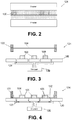
- FIGS. 2-10 A schematic depiction of a process of packaging a product to form a packaging assembly 100, such as depicted in FIG. 1 , is depicted in FIGS. 2-10 .
- the film 106 for the first subassembly 102 is exposed to a thermoforming temperature at a heating station 121, such as an oven.
- the forming temperature may be any suitable temperature for the type of material used for the film that is capable of causing the film to become pliable and capable of being stretched and deformed without tearing or breaking and that does not burn or blister the film.
- the film 106 may be heated from both sides of the film 106 as depicted in FIG. 2 or may be heated from just one side, e.g., the top or the bottom.
- the film 106 is clamped in a film frame assembly 122 at a thermoforming station 124 and stretched over a forming area of the thermoforming station 124 as depicted in FIG. 3 . Meanwhile, at least one product 108 is moved into the thermoforming station 124 for engagement with the film 106 as part of the thermoforming process. In this embodiment, three products 108 are depicted as being moved into the thermoforming station. In alternative embodiments, more or fewer products (including a single product) may be used in the thermoforming process at a time.
- the products 108 are supported on a fixture 126 in the thermoforming station 124.
- the products 108 may each be the same product although not necessarily.
- the fixture 126 may be a component of the thermoforming station 124 or may comprise a portion of a conveyor system, such as a belt that is fed through the station 124.
- One or the other or both of the film frame assembly 122 and the fixture 126 are configured to move until the film frame assembly 122 contacts the fixture 126 so that the film 106 can be brought into engagement with the products 108.
- the products 108 on the fixture 126 are used as a mold to shape the film 106 and form a container portion 110 in the film having a form fit that closely surrounds the product and conforms to the outer shape and contours of the product 108.
- thermoforming station 124 is configured to utilize vacuum pressure to cause the film 106 to be drawn around each product 108 on the fixture 126.
- Vacuum pressure may be generated in any suitable manner.
- the film frame assembly 122 may be configured to form an air tight seal with the fixture 126.
- the fixture 126 is provided with openings 128 that enable air to be drawn out of the vacuum chamber by a vacuum generator 130. As the air is drawn out of the vacuum chamber, the film 106 is drawn down toward the fixture 126 until the film 106 surrounds and closely conforms to the shape of the products 108.
- the portion of the film 106 surrounding the products 108 corresponds to the container portion 110 of the film.
- the portions 132 of the film 106 between (and around) the products 108 lie flat against the fixture 126. These portions 132 correspond to the flanges 112 of the film 106 that are used to attach the film 106 to the panels 114, either singularly or plurality.
- the thermoforming station may be configured to utilize other means of thermoforming the film using the products as the mold.
- the thermoforming station may be configured to use pressure thermoforming or mechanical thermoforming techniques.
- the positions of the film and the product may be changed so that the product is supported above the film and the film is drawn up around the products.
- the film 106 is allowed to cure around the products so that the film 106 can retain the thermoformed shape.
- the film 106 may be cured in place in the thermoforming station 124 or may be transported to a curing station (not shown) for curing.
- the film 106 may be cured in any suitable manner appropriate for the materials used. Examples of types of curing that may be used include radiant heating, cooling, forced air, microwave dryers and combinations of these types.
- the thermoformed film 106 may be singulated to separate the products 108 into individual subassemblies.
- the film 106 may be singulated in any suitable manner. As depicted in FIG. 5 , the film 106 may be singulated along die cutting lines 134 between each product 108 using a die cutting machine (Not shown). Other suitable methods of die cutting process are sufficed such as using a saw, a laser, a strip knife blade, water jet, ultrasonic, or other known singulating process. As depicted in FIG. 6 , a plurality of first packaging subassemblies 102 are formed after the film 106 is singulated.
- Each packaging subassembly 102 may include a single product 108 or multiple products (not shown).
- the first packaging subassemblies 102 may then be attached to a second packaging subassembly 104, either singularly or plurally.
- the packaging subassemblies 102, 104 may be attached to each other before singulating.
- the panel 114 of the second subassembly 104 may be provided with an anti-theft device 118 which can be attached to the packaging assembly during or after the assembly of the film to the panel.
- the anti-theft device 118 may be attached to a surface of the panel 114, e.g., using adhesive or bonding.
- a covering 120 such as a film, is placed over the anti-theft device 118 and attached to the panel 114 around the anti-theft device.
- the film 120 may undergo a process to seal the circumferential surfaces of the film 120 and the panel 114 together and minimize the likelihood of neutralizing the anti-theft device 118.
- the film 120 may comprise a rigid plastic that is opaque or clear that is sufficiently sized to cover the anti-theft device and be attached to the panel. In alternative embodiments, other types of coverings for the anti-theft device may be used.
- the first packaging subassemblies 102 may be attached to the second packaging subassemblies 104 before or after an anti-theft device 118 has been attached to the panel 114.
- the flange 112 of the film 106 of a first subassembly 102 is placed against a surface of the panel 114 of the second subassembly 104 and sealed to the panel, e.g., by adhesive. Any suitable adhesive or may be used depending upon the materials used for tray and film. Alternatively, some type of heat and/or pressure type seal may be used to seal the flange of the film to the panel.
- the film and/or the panel may be have to be resized in which case a trimming operation may be performed to trim the film 106 and/or the panel 114 to the appropriate size using any known technique as depicted in FIG. 10 .
- Mounting apertures, labels, stickers, text/image printing, and the like that are incorporated into the packaging assembly may be performed at any suitable time during the process.
- FIG. 11 and 12 depict schematically another version of the packaging process.
- the film 106 for the first packaging assembly 102 is supplied as a continuous web from a supply roll 140.
- the film 106 is fed through a heating station 121 where it is heated to a thermoforming temperature.
- the film then passes through a thermoforming station 124.
- the products 108 are positioned above the film 106.
- An upper fixture member 142 and a lower fixture member 144 are configured to come together to form an air-tight thermoforming enclosure around the products 108 and the film 106.
- the upper fixture member 142 is configured similar to the fixture 126 described above including a flat pressing portion 146 that faces toward the products 108 and a vacuum source 148 behind the pressing portion 146 for drawing the film 106 toward the products 108.
- the panels 114 for the packaging assemblies are incorporated into the process and fed over the thermoformed film and products after they leave the thermoforming station 124.
- the panel material is supplied as a continuous web from a supply roll 150 although in alternative embodiments panels may be supplied as single pieces.
- the panel material from the roll 150 is pressed onto and attached to the flanges 112 of the thermoformed film 106 prior to reaching a singulating station 152.
- the thermoformed film 106 with the products 108 contained therein and the paneling 114 attached thereto is divided, e.g., by die cutting using a die cutting machine 154, into individual packing assemblies 100.
- FIG. 13 depicts a flowchart detailing the process steps of an exemplary method of packaging a plurality of products according to the disclosure.
- a film 106 for a packaging assembly 100 is heated to a thermoforming temperature at a thermoforming station 124.
- a film frame assembly 122 is provided to hold the film 106 at a thermoforming station at S2, and a plurality of product 108 is placed and properly aligned on a fixture 126 at the thermoforming station at S3.
- the film 106 and the products are then moved into engagement with each other at the forming station such that the film 106 is deformed by the product at S4 until the film partially surrounds the product and takes on a thermoformed shape that conforms to a shape of the product.
- the film 106 is then cured with the film surrounding the portion of the product at S5.
- the first assembly 102 is then checked for any misalignment, the degree of film grip to the product 108, and other known quality defects at S6.
- the thermoformed film and product is die cut or singulated into a plurality of first packaging subassemblies 102.
- a panel 110 is provided to encapsulate the sub-packaging devices 120.
- An optional anti-theft device 112 may be adhesively attached or bonded to a surface of the panel 110 by any known attachments at S8.
- An opaque rigid film of plastic 124 is placed over the anti-theft device 112 to cover the anti-theft device 112 and seal the film 124 to the panel 110 without neutralize the anti-theft device during the sealing process S9.
- the first packaging subassemblies 102 are placed on the panels 114 of the second packaging subassemblies 104, and the flange of the films of the first packaging subassemblies 102 is sealed to the panels 114. Any excess of the film 106 and/or the panel 110 is sized and trimmed by any known techniques, mounting apertures formed, and labeling provided at S11.
Landscapes
- Engineering & Computer Science (AREA)
- Mechanical Engineering (AREA)
- Chemical & Material Sciences (AREA)
- Composite Materials (AREA)
- Packages (AREA)
- Blow-Moulding Or Thermoforming Of Plastics Or The Like (AREA)
Description
- The disclosure relates generally to packaging system and manufacturing thereof.
- Packaging for products can take many forms. One typical type of packaging comprises a display card or panel that is capable of being displayed, e.g., by hanging on a hook on a display rack. The product is held in a molded, clear plastic film that is attached to the panel. The plastic film is typically manufactured using a thermoforming process. Thermoforming is a technique often used to form packaging for products and involves heating a sheet of a thermoplastic material to a forming temperature at which the material becomes pliable. The sheet is then molded to a desired shape and cured so that it retains that shape.
- A typical thermoforming process utilizes two complementary shaped molds. The two molds include a positive mold that defines the convex portion of the shape of the film, and a negative mold that defines the concave portion of the shape of the film. With the heated material positioned between the molds, the negative mold is pressed into the positive mold, or vice versa, to form the sheet into the shape defined by the molds. The molded sheet is then cured so that it retains the molded shape. Other thermoforming processes utilize vacuum pressure to draw a heated sheet into a mold that has an inner contour with the desired shape.
Regarding packagingDE 103 43 483 A1 also discloses that pockets can be created before the products are positioned.EP 2 207 718 A2 further discloses a step of deforming a web in paper with a part that can be regarded as a product. - While such thermoforming processes are effective for packaging products, they require that a separate mold be used to mold the packaging for each product. Creating a separate mold for each product can be expensive. In many cases, a generic mold having a common shape is used for many different products of similar size and shape. As a result, the products are often able to move around within the packaging which can sometimes result in damage to the product and/or the packaging. Therefore, the object of the present invention is to provide a packaging method which is cost-effective, can easily be adapted to different forms and sizes of the products and which can effectively seal the products without damages to the product and/or the packaging. This object is solved by the method of
claim 1. Further advantageous embodiments and improvements of the invention are listed in the dependent claims. -
-
FIG. 1 is a perspective view of a packaging assembly in accordance with an embodiment; -
FIG. 2 is a schematic view of a heating station for heating the film of the packaging assembly ofFIG. 1 ; -
FIG 3 is a schematic view of a thermoforming station configured to use vacuum pressure to thermoform the film ofFIG. 2 using the products to be packaged as molds for the film prior to the heated sheet being thermoformed; -
FIG. 4 is a schematic view of the thermoforming station ofFIG. 2 after vacuum pressure has been used to draw the heated film down over the products; -
FIG. 5 is a schematic view of the thermoformed film and products ofFIG. 4 being singulated to form first packaging subassemblies; -
FIG. 6 is a schematic view of the singulated first package subassemblies ofFIG. 5 . -
FIG. 7 is a schematic view of the panel of the packaging assembly ofFIG. 1 with an anti-theft device attached thereto; -
FIG. 8 is a schematic view of the panel ofFIG. 7 with a film attached over the anti-theft device to form a second packaging subassembly; -
FIG. 9 is a schematic view of one of the singulated first packaging subassemblies ofFIG. 6 attached to the second packaging subassembly ofFIG. 8 to form a packaging assembly, such as depicted inFIG. 1 . -
FIG. 10 depicts a packaging assembly, such as depicted inFIG. 9 , with a film that overlaps the panel; -
FIG. 11 is a schematic view of another embodiment of a thermoforming packaging process in which the product to be packaged is used as the mold for the packaging film; -
FIG. 12 is another schematic view of the packaging process ofFIG. 11 . -
FIG. 13 is a flowchart describing an embodiment of a method for a packaging assembly. - For the purposes of promoting an understanding of the principles of the disclosure, reference will now be made to the embodiments illustrated in the drawings and described in the following written specification. It is understood that no limitation to the scope of the disclosure is thereby intended. It is further understood that the present disclosure includes any alterations and modifications to the illustrated embodiments and includes further applications of the principles of the disclosure as would normally occur to one of ordinary skill in the art to which this disclosure pertains.
- The present disclosure is directed to a packaging assembly for a product, such as a tool, accessory tool, part, and the like, and a method of packaging such products. An exemplary embodiment of a
packaging assembly 100 in accordance with the present disclosure is depicted inFIG. 1 . The packaging assembly includes afirst subassembly 102 and asecond subassembly 104. Thefirst subassembly 102 includes afilm 106 and at least oneproduct 108. As explained below, thefilm 106 comprises a thermoformed sheet that has been formed to include acontainer portion 110 and aflange portion 112. Theproduct 108 is received in thecontainer portion 110 of thefilm 106 and theflange portion 112 is attached to thesecond subassembly 104. - The
film 106 can be a rigid film or a semi-rigid film, and can be clear or transparent, or it can be colored. For example, thefilm 106 can be polyethylene terephthalate (PET), polypropylene (PP), polyvinyl chloride (PVC), polystyrene (PS), special polyethylene terephthalate (SPET), alternative polyethylene terephthalate (APET), laminated combination of thermoplastic and non-thermoplastic materials or other known thermoplastic and non-thermoplastic materials. Thefilm 106 can be a single layer structure or a multi-layer structure. - As explained below, the
product 108 is used to mold or shape thefilm 106 during the thermoforming process to form at least one pocket in thefilm 106 that encapsulates theproduct 108 and serves as thecontainer portion 110 of the package. Therefore, thecontainer portion 110 closely conforms to the contours and outer shape of theproduct 108. The exact shape depends on the type of product. In the embodiment ofFIG. 1 , theproduct 108 comprises a drill bit. Examples of other products that can be packaged in the packaging assembly using the methods described herein include, but are not limited to, a nut setter, a saw blade, a jig saw blade, a rebar cutter, a hammer steel, a hammer drill bit, a planar blade, a diamond abrasive blade, a screwdriver bit, a router bit, a reciprocating saw blade, a cutting accessory, a scraping or removal accessory, spark plugs, or other known power tool and non-power tool accessories. - The
second subassembly 104 includes asupport member 114 that provides a structure for attaching thefirst subassembly 102 and that enables thepackaging assembly 100 to be easily transported, stored, and displayed, e.g., by hanging or standing, as a unit. In the embodiment ofFIG. 1 , thesupport member 114 comprises a panel having a generally planar configuration. Thepanel 114 can be a rigid film or a semi-rigid film, and can be clear or transparent, or it can be colored. For example, the panel can be polyethylene terephthalate (PET), polypropylene (PP), polyvinyl chloride (PVC), polystyrene (PS), special polyethylene terephthalate (SPET), alternative polyethylene terephthalate (APET), laminated combination of thermoplastic and non-thermoplastic materials or other known thermoplastic and non-thermoplastic materials. The panel can be a single layer structure or a multi-layer structure. In alternative embodiments, the panel may be formed of other materials, such as cardboard. - The
panel 114 is sized and shaped in a manner appropriate for theproduct 108 contained in thefilm 106 of thefirst subassembly 102. The size of thepanel 114 is at least sufficient to provide a surface for attaching theflange 112 of thefilm 106. In alternative embodiments, asupport member 114 may be provided in configurations that are not planar, such as a box, cylinder, or other type of three-dimensional shape. - As depicted in
FIG. 1 , thepanel 114 includes amounting aperture 116 for placing thepackaging assembly 100 over an outwardly extending rod or hook (not shown). In alternative embodiments, thepanel 114 or other type of support member may be provided with feet or a base (not shown) that enable thepackaging assembly 100 to stand up right, e.g., for placement on a display shelf. The panel may also include labels, markings, printed text, pictures, and the like (not shown) for providing information to consumers, such as weight, quantity, measurement, industry standard, logo, warning statement, model, part number, icon, or other known information. - The panel or
support member 114 may be provided with an anti-theft device 118 (FIGS. 7-10 ). Theanti-theft device 118 can be a security tag, such as a Sensormatic tag, a near field communication (NFC) tag, a RFID tag, an identification tag, an electronic tag, for example, or other known security device with and without a built-in tracking enabled software. Ananti-theft device 118 may be secured to thepanel 114 in any suitable manner and at any suitable location on the panel. In one embodiment, theanti-theft device 118 is attached to the panel by a film 120 (FIGS. 7-10 ) that covers theanti-theft device 118 and is adhered to thepanel 114 around the device. Theanti-theft device 118 can be left visible on thepackaging assembly 100 to provide a visual theft deterrent, or thedevice 118 can be concealed on or in the packaging assembly to prevent removal. - A schematic depiction of a process of packaging a product to form a
packaging assembly 100, such as depicted inFIG. 1 , is depicted inFIGS. 2-10 . As depicted inFIG. 2 , thefilm 106 for thefirst subassembly 102 is exposed to a thermoforming temperature at aheating station 121, such as an oven. The forming temperature may be any suitable temperature for the type of material used for the film that is capable of causing the film to become pliable and capable of being stretched and deformed without tearing or breaking and that does not burn or blister the film. Thefilm 106 may be heated from both sides of thefilm 106 as depicted inFIG. 2 or may be heated from just one side, e.g., the top or the bottom. - The
film 106 is clamped in afilm frame assembly 122 at athermoforming station 124 and stretched over a forming area of thethermoforming station 124 as depicted inFIG. 3 . Meanwhile, at least oneproduct 108 is moved into thethermoforming station 124 for engagement with thefilm 106 as part of the thermoforming process. In this embodiment, threeproducts 108 are depicted as being moved into the thermoforming station. In alternative embodiments, more or fewer products (including a single product) may be used in the thermoforming process at a time. - The
products 108 are supported on afixture 126 in thethermoforming station 124. Theproducts 108 may each be the same product although not necessarily. Thefixture 126 may be a component of thethermoforming station 124 or may comprise a portion of a conveyor system, such as a belt that is fed through thestation 124. One or the other or both of thefilm frame assembly 122 and thefixture 126 are configured to move until thefilm frame assembly 122 contacts thefixture 126 so that thefilm 106 can be brought into engagement with theproducts 108. Theproducts 108 on thefixture 126 are used as a mold to shape thefilm 106 and form acontainer portion 110 in the film having a form fit that closely surrounds the product and conforms to the outer shape and contours of theproduct 108. - To thermoform the
film 106, some type of pressure is used to cause the film to surround and closely conform to the products. In one embodiment, thethermoforming station 124 is configured to utilize vacuum pressure to cause thefilm 106 to be drawn around eachproduct 108 on thefixture 126. Vacuum pressure may be generated in any suitable manner. As an example, thefilm frame assembly 122 may be configured to form an air tight seal with thefixture 126. Thefixture 126 is provided withopenings 128 that enable air to be drawn out of the vacuum chamber by avacuum generator 130. As the air is drawn out of the vacuum chamber, thefilm 106 is drawn down toward thefixture 126 until thefilm 106 surrounds and closely conforms to the shape of theproducts 108. - The portion of the
film 106 surrounding theproducts 108 corresponds to thecontainer portion 110 of the film. As can be seen inFIG. 4 , theportions 132 of thefilm 106 between (and around) theproducts 108 lie flat against thefixture 126. Theseportions 132 correspond to theflanges 112 of thefilm 106 that are used to attach thefilm 106 to thepanels 114, either singularly or plurality. As an alternative to vacuum pressure, the thermoforming station may be configured to utilize other means of thermoforming the film using the products as the mold. For example, the thermoforming station may be configured to use pressure thermoforming or mechanical thermoforming techniques. In addition, the positions of the film and the product may be changed so that the product is supported above the film and the film is drawn up around the products. - After the
film 106 has been shaped, thefilm 106 is allowed to cure around the products so that thefilm 106 can retain the thermoformed shape. Thefilm 106 may be cured in place in thethermoforming station 124 or may be transported to a curing station (not shown) for curing. Thefilm 106 may be cured in any suitable manner appropriate for the materials used. Examples of types of curing that may be used include radiant heating, cooling, forced air, microwave dryers and combinations of these types. - Before or after the
film 106 has been cured, thethermoformed film 106 may be singulated to separate theproducts 108 into individual subassemblies. Thefilm 106 may be singulated in any suitable manner. As depicted inFIG. 5 , thefilm 106 may be singulated along die cuttinglines 134 between eachproduct 108 using a die cutting machine (Not shown). Other suitable methods of die cutting process are sufficed such as using a saw, a laser, a strip knife blade, water jet, ultrasonic, or other known singulating process. As depicted inFIG. 6 , a plurality offirst packaging subassemblies 102 are formed after thefilm 106 is singulated. Eachpackaging subassembly 102 may include asingle product 108 or multiple products (not shown). Thefirst packaging subassemblies 102 may then be attached to asecond packaging subassembly 104, either singularly or plurally. In alternative embodiments, thepackaging subassemblies - As depicted in
FIG. 7 , thepanel 114 of thesecond subassembly 104 may be provided with ananti-theft device 118 which can be attached to the packaging assembly during or after the assembly of the film to the panel. Theanti-theft device 118 may be attached to a surface of thepanel 114, e.g., using adhesive or bonding. To protect the anti-theft device, a covering 120, such as a film, is placed over theanti-theft device 118 and attached to thepanel 114 around the anti-theft device. To encapsulate theanti-theft device 112, thefilm 120 may undergo a process to seal the circumferential surfaces of thefilm 120 and thepanel 114 together and minimize the likelihood of neutralizing theanti-theft device 118. Thefilm 120 may comprise a rigid plastic that is opaque or clear that is sufficiently sized to cover the anti-theft device and be attached to the panel. In alternative embodiments, other types of coverings for the anti-theft device may be used. - The
first packaging subassemblies 102 may be attached to thesecond packaging subassemblies 104 before or after ananti-theft device 118 has been attached to thepanel 114. As shown inFIG. 9 , theflange 112 of thefilm 106 of afirst subassembly 102 is placed against a surface of thepanel 114 of thesecond subassembly 104 and sealed to the panel, e.g., by adhesive. Any suitable adhesive or may be used depending upon the materials used for tray and film. Alternatively, some type of heat and/or pressure type seal may be used to seal the flange of the film to the panel. - In some cases, the film and/or the panel may be have to be resized in which case a trimming operation may be performed to trim the
film 106 and/or thepanel 114 to the appropriate size using any known technique as depicted inFIG. 10 . Mounting apertures, labels, stickers, text/image printing, and the like that are incorporated into the packaging assembly may be performed at any suitable time during the process. -
FIG. 11 and 12 depict schematically another version of the packaging process. In this embodiment, thefilm 106 for thefirst packaging assembly 102 is supplied as a continuous web from asupply roll 140. Thefilm 106 is fed through aheating station 121 where it is heated to a thermoforming temperature. The film then passes through athermoforming station 124. In thethermoforming station 124, theproducts 108 are positioned above thefilm 106. Anupper fixture member 142 and alower fixture member 144 are configured to come together to form an air-tight thermoforming enclosure around theproducts 108 and thefilm 106. Theupper fixture member 142 is configured similar to thefixture 126 described above including a flatpressing portion 146 that faces toward theproducts 108 and avacuum source 148 behind thepressing portion 146 for drawing thefilm 106 toward theproducts 108. - In this embodiment, the
panels 114 for the packaging assemblies are incorporated into the process and fed over the thermoformed film and products after they leave thethermoforming station 124. The panel material is supplied as a continuous web from asupply roll 150 although in alternative embodiments panels may be supplied as single pieces. The panel material from theroll 150 is pressed onto and attached to theflanges 112 of thethermoformed film 106 prior to reaching asingulating station 152. At thesingulating station 152, thethermoformed film 106 with theproducts 108 contained therein and thepaneling 114 attached thereto is divided, e.g., by die cutting using adie cutting machine 154, intoindividual packing assemblies 100. -
FIG. 13 depicts a flowchart detailing the process steps of an exemplary method of packaging a plurality of products according to the disclosure. At S1, afilm 106 for apackaging assembly 100 is heated to a thermoforming temperature at athermoforming station 124. Afilm frame assembly 122 is provided to hold thefilm 106 at a thermoforming station at S2, and a plurality ofproduct 108 is placed and properly aligned on afixture 126 at the thermoforming station at S3. Thefilm 106 and the products are then moved into engagement with each other at the forming station such that thefilm 106 is deformed by the product at S4 until the film partially surrounds the product and takes on a thermoformed shape that conforms to a shape of the product. Thefilm 106 is then cured with the film surrounding the portion of the product at S5. - The
first assembly 102 is then checked for any misalignment, the degree of film grip to theproduct 108, and other known quality defects at S6. At S7, the thermoformed film and product is die cut or singulated into a plurality offirst packaging subassemblies 102. To encapsulate thesub-packaging devices 120, apanel 110 is provided. An optionalanti-theft device 112 may be adhesively attached or bonded to a surface of thepanel 110 by any known attachments at S8. An opaque rigid film ofplastic 124 is placed over theanti-theft device 112 to cover theanti-theft device 112 and seal thefilm 124 to thepanel 110 without neutralize the anti-theft device during the sealing process S9. - At S10, the
first packaging subassemblies 102 are placed on thepanels 114 of thesecond packaging subassemblies 104, and the flange of the films of thefirst packaging subassemblies 102 is sealed to thepanels 114. Any excess of thefilm 106 and/or thepanel 110 is sized and trimmed by any known techniques, mounting apertures formed, and labeling provided at S11. - The above described packaging systems and methods can save time and reduce costs in the packaging process as a separate mold does not have to be formed for each product and separate steps do not have to be performed to create the mold, then fill the molds with the products. In addition, numerous modifications of the above-described processes and systems are possible and fall within the scope of the present disclosure. For example, although many of the steps describe above were described as being performed separately or at separate stations, a person of ordinary skill in the art would understand that certain steps may be combined or performed simultaneously.
- While the disclosure has been illustrated and described in detail in the drawings and foregoing description, the same should be considered as illustrative and not restrictive in character. It is understood that only the preferred embodiments have been presented and that all changes, modifications that come within the the scope of the appended claims are desired to be protected.
Claims (8)
- A method of packaging a plurality of products (108), comprising:a) heating a film (106) of plastic material to a forming temperature at a heating station (121) until it is thermoformable and passing it to a thermoforming station (124);b) positioning a plurality of products (108) above the heated film (106) of plastic material in the thermoforming station (124) which includes a flat pressing portion (146) and a vacuum source (148) behind the flat pressing portion (146);c) wherein the flat pressing portion (146) presses the plurality of products (108) into the heated film (106) from above, such that pockets (110) are formed in the heated film (106) by the products (108) and extend below the film (106), andd) wherein the heated film (106) is drawn upward into contact with the flat pressing portion (146) to form a flange portion (112) around the products.
- The method of claim 1, further comprising the step of curing (S5) the heated film (106) with the plurality of products (108) encapsulated in the pockets (110) in the heated films (106).
- The method of Claim 1, wherein the film (106) of plastic material is supplied from a roll (140) as a continuous web that is guided through the thermoforming station (124).
- The method of Claim 1, wherein a packaging panel (114) is pressed onto the flange portions (112) of the thermoformed film (106) prior to reaching a singulating station (152) where the film (106) with the products (108) contained in the pockets (110) is cut into individual packing assemblies (100).
- The method of claim 4, wherein the singulating includes die cutting the film (106) and the packaging panel (114) into the plurality of packaging assemblies using a die-cutting machine (154) at the singulating station (152).
- The method of claim 1 wherein the product (108) comprises a tool product.
- The method of claim 6 wherein the tool product (108) comprises an accessory tool or toot bit.
- The method of claim 4, wherein the packaging panel (114) is supplied from a roll (150) and fed over the continuous web between the thermoforming station (124) and the singulating station (152) such that the packaging panel (114) is attached to the flange portions (112) prior to reaching the singulating station (152).
Applications Claiming Priority (2)
| Application Number | Priority Date | Filing Date | Title |
|---|---|---|---|
| US201261615966P | 2012-03-27 | 2012-03-27 | |
| PCT/US2013/032101 WO2013148317A1 (en) | 2012-03-27 | 2013-03-15 | Packaging system and manufacturing thereof |
Publications (2)
| Publication Number | Publication Date |
|---|---|
| EP2834155A1 EP2834155A1 (en) | 2015-02-11 |
| EP2834155B1 true EP2834155B1 (en) | 2017-08-16 |
Family
ID=48050286
Family Applications (1)
| Application Number | Title | Priority Date | Filing Date |
|---|---|---|---|
| EP13714780.7A Active EP2834155B1 (en) | 2012-03-27 | 2013-03-15 | Packaging system and manufacturing thereof |
Country Status (4)
| Country | Link |
|---|---|
| US (2) | US10479579B2 (en) |
| EP (1) | EP2834155B1 (en) |
| CN (1) | CN104254482B (en) |
| WO (1) | WO2013148317A1 (en) |
Families Citing this family (12)
| Publication number | Priority date | Publication date | Assignee | Title |
|---|---|---|---|---|
| US20140083884A1 (en) * | 2011-12-15 | 2014-03-27 | Husqvarna Ab | Chainsaw Bar / Chain Packaging Technique and Packaging Employed for the Same |
| US20130248406A1 (en) * | 2012-03-21 | 2013-09-26 | Multi Packaging Solutions | Tamper evident packaging |
| DE102014114660A1 (en) * | 2014-10-09 | 2016-04-14 | Medipack Ag | Method for packaging articles in blister packs |
| WO2017015611A1 (en) * | 2015-07-23 | 2017-01-26 | Robert Bosch Gmbh | Packaging system and manufacturing thereof |
| WO2017057458A1 (en) * | 2015-09-30 | 2017-04-06 | サトーホールディングス株式会社 | Container and container opening state determination method |
| JP6446352B2 (en) * | 2015-12-10 | 2018-12-26 | 大森機械工業株式会社 | Packaging equipment |
| US10486876B2 (en) | 2017-06-08 | 2019-11-26 | Robert Bosch Tool Corporation | Hang Tag |
| DE202018103398U1 (en) * | 2018-01-23 | 2018-06-22 | Van Genechten Packaging N.V. | packaging |
| US10894645B2 (en) * | 2019-03-01 | 2021-01-19 | Robert Bosch Tool Corporation | Elongated tool hang tag package with bridge strap |
| US11395711B2 (en) * | 2019-06-05 | 2022-07-26 | Stryker European Operations Limited | Packaging systems and methods for mounting a tool on a surgical device using the same |
| US10675774B1 (en) * | 2019-10-17 | 2020-06-09 | Moshe Epstein | Cross-cut stabilizer used in horizontal, form, fill, and seal packaging machines |
| EP4311793B1 (en) * | 2022-07-27 | 2024-05-22 | Hilti Aktiengesellschaft | Merchandise hanger, sales product and method of manufacture |
Citations (2)
| Publication number | Priority date | Publication date | Assignee | Title |
|---|---|---|---|---|
| DE10343483A1 (en) * | 2003-09-19 | 2005-04-28 | Bosch Gmbh Robert | Moulding tool for forming projections, comprises two plate units which can be driven towards each other, spring elements and a pressure spring and adjuster unit |
| EP2207718A2 (en) * | 2007-11-13 | 2010-07-21 | IMA FLAVOUR S.r.l. | Machine for making pods containing infusion products |
Family Cites Families (70)
| Publication number | Priority date | Publication date | Assignee | Title |
|---|---|---|---|---|
| US2879635A (en) * | 1956-10-02 | 1959-03-31 | Brock Herbert William | Method of packaging articles |
| US2931495A (en) * | 1956-10-11 | 1960-04-05 | Nat Cleveland Corp | Display package |
| US3472723A (en) * | 1964-10-14 | 1969-10-14 | Jerome H Lemelson | Container manufacture |
| US3226910A (en) * | 1964-11-13 | 1966-01-04 | Edmond A Steffey | Method for packaging appliques |
| US3785276A (en) * | 1969-02-06 | 1974-01-15 | Norr Eng Mfg Corp | Equipment for conditioning and packaging a product |
| US3507383A (en) * | 1969-06-12 | 1970-04-21 | Stone Container Corp | Skin package |
| US3796306A (en) * | 1969-08-25 | 1974-03-12 | Union Camp Corp | Display package |
| US3636678A (en) * | 1970-03-09 | 1972-01-25 | Du Pont | Packaging method and package made thereby |
| US3703234A (en) * | 1970-07-27 | 1972-11-21 | Howard Hardware Prod | Display packages for drills, bits and similar boring tools, providing means to test if proper size for a given bolt, screw or dowel |
| US3848393A (en) * | 1971-02-04 | 1974-11-19 | Monaghan Automated Syst Inc | Packaging machine and process |
| US3701229A (en) * | 1971-02-19 | 1972-10-31 | Weldotron Corp | Method and apparatus for skin-packaging articles between film-on-film |
| DE2364565C2 (en) * | 1973-12-24 | 1983-01-05 | Multivac Sepp Haggenmüller KG, 8941 Wolfertschwenden | Method and vacuum packaging device for producing a package |
| US3942829A (en) * | 1973-12-27 | 1976-03-09 | Sensormatic Electronics Corporation | Reusable security tag |
| US3910410A (en) * | 1974-03-19 | 1975-10-07 | Continental Can Co | Resealable package |
| DE2532958A1 (en) * | 1974-08-22 | 1976-03-04 | Schreiber Cheese Co L D | PACKAGING AND METHOD OF MANUFACTURING THEREOF |
| US4034536A (en) * | 1976-06-11 | 1977-07-12 | Mahaffy & Harder Engineering Company | Packaging apparatus and techniques |
| US4120984A (en) * | 1976-10-27 | 1978-10-17 | The Pillsbury Company | Process for preparing food in the package |
| US4229927A (en) * | 1978-10-06 | 1980-10-28 | J. Sainsbury Limited | Process and apparatus for vacuum packing |
| US4254868A (en) * | 1979-02-05 | 1981-03-10 | Sensormatic Electronics Corporation | Enclosure for a security tag and extraction implement |
| US4324331A (en) * | 1980-08-08 | 1982-04-13 | Zimmer, Inc. | Packaging for surgical implements |
| ATE24457T1 (en) * | 1982-10-13 | 1987-01-15 | Leguay Emballages | CARRIER PLATE FOR SKIN PACKING OF SMALL PARTS. |
| US4537011A (en) * | 1982-11-26 | 1985-08-27 | W. R. Grace & Co., Cryovac Div. | Vacuum packaging |
| US4642239A (en) * | 1984-01-09 | 1987-02-10 | Transparent Paper Plc | Packaging of fresh meat |
| FR2612497B1 (en) * | 1987-03-17 | 1989-12-01 | Svem | PACKAGING FOR THE PACKAGING OF PRODUCTS UNDER A TRANSPARENT FILM, METHOD FOR PRODUCING THE SAME AND DEVICE FOR CARRYING OUT SAID METHOD |
| US4958480A (en) * | 1988-10-07 | 1990-09-25 | W. R. Grace & Co.-Conn. | High profile shrink package |
| US5127974A (en) * | 1989-05-15 | 1992-07-07 | Kansai Paint Co., Ltd. | Method of protecting coating film |
| US4958731A (en) * | 1989-11-22 | 1990-09-25 | Duracell Inc. | Battery package |
| US5325654A (en) * | 1992-06-19 | 1994-07-05 | Minnesota Mining And Manufacturing Company | Carrier tape with cover strip |
| US5390472A (en) * | 1992-06-19 | 1995-02-21 | Minnesota Mining And Manufacturing Company | Carrier tape with cover strip |
| DK0659150T3 (en) * | 1992-09-09 | 1997-09-29 | Fisons Plc | Pharmaceutical packaging. |
| FR2729639B1 (en) * | 1995-01-20 | 1997-04-18 | Lalande Soc Civ | PACKAGING METHOD AND INSTALLATION AND PACKAGED OBJECTS THUS OBTAINED |
| US5715945A (en) * | 1996-03-18 | 1998-02-10 | Cortec Corporation | Vapor phase corrosion inhibitor package utilizing plastic packaging envelopes |
| EP0845411B1 (en) * | 1996-11-29 | 2002-02-13 | Kabushiki Kaisha Hayashibara Seibutsu Kagaku Kenkyujo | Package for an inclusion product and process for making same |
| JP4170401B2 (en) * | 1997-04-17 | 2008-10-22 | グルッポ エックス ディ エックス グルッポ エス・アール・エル | Dimensionally and structurally stable object, in particular a method for obtaining a disposable container manufactured from a flexible film and the object obtained by this method |
| DE19928368A1 (en) | 1998-06-22 | 1999-12-23 | Hawera Probst Gmbh | Sales packing, especially for holding tools |
| US6044622A (en) * | 1999-01-11 | 2000-04-04 | Cryovac, Inc. | Method and apparatus for producing a package having a peelable film with a tab to facilitate peeling |
| GB9905214D0 (en) * | 1999-03-08 | 1999-04-28 | British Aerospace | Vacuum packaging of articles |
| FR2790741B1 (en) * | 1999-03-12 | 2001-06-01 | Scopic | PACKAGING OF OBJECTS BY PELLIPLACAGE ON A CARTON SUPPORT, WITH AN INTEGRATED ANTI-THEFT TRACKER |
| US6726611B2 (en) * | 1999-08-17 | 2004-04-27 | Display Pack, Inc. | Display package and method of manufacture |
| JP3971065B2 (en) | 1999-09-13 | 2007-09-05 | 富士フイルム株式会社 | Camera sales package |
| EP1457431A3 (en) * | 1999-11-17 | 2007-07-04 | Aquasol Limited | Injection moulded water-soluble container |
| GB9928987D0 (en) * | 1999-12-09 | 2000-02-02 | Turner Intellect Property Ltd | Improvements in or relating to packaging/display of products |
| AU2002222314A1 (en) * | 2000-11-29 | 2002-06-11 | Element Six (Pty) Ltd | Web strip for tool inserts |
| FR2827258B1 (en) * | 2001-07-11 | 2003-10-31 | Erca Formseal | PROCESS AND INSTALLATION FOR THERMOFORMING, FILLING AND CLOSING OF UNDERPACKING CONTAINERS |
| DE10227610A1 (en) * | 2002-06-20 | 2004-01-15 | Multivac Sepp Haggenmüller GmbH & Co. | Packaging method and apparatus |
| DE10310135A1 (en) | 2003-03-07 | 2004-09-16 | Checkpoint Systems International Gmbh | Security label and method for securing objects |
| US6729468B1 (en) * | 2003-03-28 | 2004-05-04 | Thomas N Dobmeier | Circular saw blade holder |
| GB2401091A (en) * | 2003-05-02 | 2004-11-03 | Reckitt Benckiser | Packaging of compacted particulate compositions |
| US7233246B2 (en) * | 2004-04-14 | 2007-06-19 | Smartguard, Llc | Hard cover product with spine-disposed concealed security device |
| US7152734B2 (en) * | 2004-07-14 | 2006-12-26 | Tsan-Nien Chen | Sealed packing box with a size checking space |
| CA2522967A1 (en) * | 2004-10-08 | 2006-04-08 | John R. Nottingham | Package with product demonstration feature |
| US7355516B2 (en) * | 2004-12-23 | 2008-04-08 | Checkpoint Systems, Inc. | Method and apparatus for protecting culinary products |
| US7624865B2 (en) * | 2005-03-08 | 2009-12-01 | Robert Bosch Gmbh | Specialty product hang tag |
| US20060278551A1 (en) * | 2005-06-10 | 2006-12-14 | Mark Iv Industries Corp. | Shielded retail packaging for transponder |
| US7571810B2 (en) * | 2005-09-08 | 2009-08-11 | One Source Industries, Llc | Printed packaging |
| US20070170087A1 (en) * | 2006-01-25 | 2007-07-26 | Narpes William R Jr | Blister package with thumb recess and self dispensing features |
| US7614498B2 (en) * | 2006-05-04 | 2009-11-10 | Mattel, Inc. | Distressed packaging with extended visual element |
| CN100447911C (en) * | 2006-06-16 | 2008-12-31 | 李霖 | Soft magnetic material offset piece manufacturing method and anti-theft acoustic magnetic label using the same |
| PL2033764T3 (en) * | 2006-06-27 | 2011-09-30 | Idm World S L | Machine for forming, filling and closing expanded-polymer containers |
| US8402723B2 (en) * | 2007-07-16 | 2013-03-26 | Cryovac, Inc. | Vacuum skin packaging method and apparatus |
| US7681732B2 (en) * | 2008-01-11 | 2010-03-23 | Cryovac, Inc. | Laminated lidstock |
| US8047368B2 (en) * | 2008-01-23 | 2011-11-01 | Curwood, Inc. | Vacuum skin packaging laminate, package and process for using same |
| US8334776B2 (en) * | 2009-06-14 | 2012-12-18 | Xiao Hui Yang | Electronic article surveillance carrier and tag |
| US20100255162A1 (en) * | 2009-04-06 | 2010-10-07 | Cryovac, Inc. | Packaging with on-demand oxygen generation |
| US20100301512A1 (en) * | 2009-05-26 | 2010-12-02 | Gm Global Technology Operations, Inc. | Packaging and de-packaging methods using shape memory polymers |
| US20100314277A1 (en) * | 2009-06-11 | 2010-12-16 | Stanley Black & Decker, Inc. | Tape rule anti-theft device and package |
| CN201447067U (en) | 2009-06-16 | 2010-05-05 | 何宗荣 | Skin packaging machine |
| US8407973B2 (en) * | 2009-07-29 | 2013-04-02 | General Mills, Inc. | Food packaging with vertical to horizontal transfer loading |
| US8328016B2 (en) * | 2009-09-04 | 2012-12-11 | International Paper Company | Display package |
| US8083058B2 (en) * | 2010-05-27 | 2011-12-27 | The Gillette Company | Consumer product package with stabilizing insert |
-
2013
- 2013-03-15 EP EP13714780.7A patent/EP2834155B1/en active Active
- 2013-03-15 US US13/833,409 patent/US10479579B2/en active Active
- 2013-03-15 WO PCT/US2013/032101 patent/WO2013148317A1/en active Application Filing
- 2013-03-15 CN CN201380022270.6A patent/CN104254482B/en active Active
-
2015
- 2015-10-07 US US14/877,133 patent/US20160023829A1/en not_active Abandoned
Patent Citations (2)
| Publication number | Priority date | Publication date | Assignee | Title |
|---|---|---|---|---|
| DE10343483A1 (en) * | 2003-09-19 | 2005-04-28 | Bosch Gmbh Robert | Moulding tool for forming projections, comprises two plate units which can be driven towards each other, spring elements and a pressure spring and adjuster unit |
| EP2207718A2 (en) * | 2007-11-13 | 2010-07-21 | IMA FLAVOUR S.r.l. | Machine for making pods containing infusion products |
Also Published As
| Publication number | Publication date |
|---|---|
| CN104254482B (en) | 2018-03-30 |
| US20130270136A1 (en) | 2013-10-17 |
| US10479579B2 (en) | 2019-11-19 |
| US20160023829A1 (en) | 2016-01-28 |
| WO2013148317A1 (en) | 2013-10-03 |
| EP2834155A1 (en) | 2015-02-11 |
| CN104254482A (en) | 2014-12-31 |
Similar Documents
| Publication | Publication Date | Title |
|---|---|---|
| EP2834155B1 (en) | Packaging system and manufacturing thereof | |
| US20170021986A1 (en) | Packaging System and Manufacturing Thereof | |
| DK1935789T4 (en) | Fremgangsmåde og anlæg til gastæt emballering af genstande. | |
| CA2552111C (en) | Method for the gas-tight packaging of objects using a film material fitting tightly on the objects; and a device for the gas-tight packaging of objects | |
| EP2021248B1 (en) | Vacuum skin packaging apparatus and process | |
| US5404693A (en) | Method for making plastic blister packages | |
| US8381497B2 (en) | Method and packaging machine for packaging products | |
| US4915231A (en) | Packaging for packaging of products under a transparent film, process for performing this packaging and device for using this process | |
| US20090159479A1 (en) | Display packaging system | |
| US6540073B1 (en) | Sales packaging | |
| EP2692646B1 (en) | Skin packaging machine | |
| KR920010468B1 (en) | Method and device for applying a provisional protective covering to internal cepholstery | |
| US3279144A (en) | Method of partially encapsulating and mounting merchandise for display | |
| US4219987A (en) | Method for skin packaging using platen forming of the film, and packages produced thereby | |
| EP3914434B1 (en) | A method and tool for manufacturing a container from a thermoplastic material and container | |
| US20130180878A1 (en) | Plastic packaging, and method and apparatus for producing same | |
| US11932440B2 (en) | Thermoforming packaging machine | |
| AU2011101019A4 (en) | Moulded fruit packaging liners and method of making same | |
| US20040256051A1 (en) | Method of manufacturing container covers | |
| KR101430513B1 (en) | package include grip film and manufacturing method thereof | |
| JPH05318628A (en) | Producing device for paper-made protective body | |
| GB2322092A (en) | Manufacturing an article with a rim | |
| JPS62271806A (en) | Method of packaging package with annular reinforcing rib | |
| KR20110015843A (en) | Process for preparing blister packaging sheet with easy peelable cover sheet |
Legal Events
| Date | Code | Title | Description |
|---|---|---|---|
| PUAI | Public reference made under article 153(3) epc to a published international application that has entered the european phase |
Free format text: ORIGINAL CODE: 0009012 |
|
| 17P | Request for examination filed |
Effective date: 20141027 |
|
| AK | Designated contracting states |
Kind code of ref document: A1 Designated state(s): AL AT BE BG CH CY CZ DE DK EE ES FI FR GB GR HR HU IE IS IT LI LT LU LV MC MK MT NL NO PL PT RO RS SE SI SK SM TR |
|
| AX | Request for extension of the european patent |
Extension state: BA ME |
|
| DAX | Request for extension of the european patent (deleted) | ||
| 17Q | First examination report despatched |
Effective date: 20151112 |
|
| STAA | Information on the status of an ep patent application or granted ep patent |
Free format text: STATUS: EXAMINATION IS IN PROGRESS |
|
| REG | Reference to a national code |
Ref country code: DE Ref legal event code: R079 Ref document number: 602013025078 Country of ref document: DE Free format text: PREVIOUS MAIN CLASS: B65B0011520000 Ipc: B65B0047020000 |
|
| RIC1 | Information provided on ipc code assigned before grant |
Ipc: B65B 9/04 20060101ALI20170227BHEP Ipc: B65D 85/00 20060101ALI20170227BHEP Ipc: B65D 75/36 20060101ALI20170227BHEP Ipc: B65B 61/06 20060101ALI20170227BHEP Ipc: B65D 75/32 20060101ALI20170227BHEP Ipc: B65D 65/38 20060101ALI20170227BHEP Ipc: B65B 47/02 20060101AFI20170227BHEP Ipc: B65D 79/02 20060101ALI20170227BHEP Ipc: B65B 47/10 20060101ALI20170227BHEP Ipc: G08B 13/24 20060101ALI20170227BHEP |
|
| GRAP | Despatch of communication of intention to grant a patent |
Free format text: ORIGINAL CODE: EPIDOSNIGR1 |
|
| STAA | Information on the status of an ep patent application or granted ep patent |
Free format text: STATUS: GRANT OF PATENT IS INTENDED |
|
| INTG | Intention to grant announced |
Effective date: 20170407 |
|
| GRAS | Grant fee paid |
Free format text: ORIGINAL CODE: EPIDOSNIGR3 |
|
| GRAA | (expected) grant |
Free format text: ORIGINAL CODE: 0009210 |
|
| STAA | Information on the status of an ep patent application or granted ep patent |
Free format text: STATUS: THE PATENT HAS BEEN GRANTED |
|
| AK | Designated contracting states |
Kind code of ref document: B1 Designated state(s): AL AT BE BG CH CY CZ DE DK EE ES FI FR GB GR HR HU IE IS IT LI LT LU LV MC MK MT NL NO PL PT RO RS SE SI SK SM TR |
|
| REG | Reference to a national code |
Ref country code: GB Ref legal event code: FG4D |
|
| REG | Reference to a national code |
Ref country code: CH Ref legal event code: EP |
|
| REG | Reference to a national code |
Ref country code: IE Ref legal event code: FG4D |
|
| REG | Reference to a national code |
Ref country code: AT Ref legal event code: REF Ref document number: 918787 Country of ref document: AT Kind code of ref document: T Effective date: 20170915 |
|
| REG | Reference to a national code |
Ref country code: DE Ref legal event code: R096 Ref document number: 602013025078 Country of ref document: DE |
|
| REG | Reference to a national code |
Ref country code: CH Ref legal event code: NV Representative=s name: HEPP WENGER RYFFEL AG, CH |
|
| REG | Reference to a national code |
Ref country code: NL Ref legal event code: MP Effective date: 20170816 |
|
| REG | Reference to a national code |
Ref country code: LT Ref legal event code: MG4D |
|
| REG | Reference to a national code |
Ref country code: AT Ref legal event code: MK05 Ref document number: 918787 Country of ref document: AT Kind code of ref document: T Effective date: 20170816 |
|
| PG25 | Lapsed in a contracting state [announced via postgrant information from national office to epo] |
Ref country code: SE Free format text: LAPSE BECAUSE OF FAILURE TO SUBMIT A TRANSLATION OF THE DESCRIPTION OR TO PAY THE FEE WITHIN THE PRESCRIBED TIME-LIMIT Effective date: 20170816 Ref country code: NO Free format text: LAPSE BECAUSE OF FAILURE TO SUBMIT A TRANSLATION OF THE DESCRIPTION OR TO PAY THE FEE WITHIN THE PRESCRIBED TIME-LIMIT Effective date: 20171116 Ref country code: FI Free format text: LAPSE BECAUSE OF FAILURE TO SUBMIT A TRANSLATION OF THE DESCRIPTION OR TO PAY THE FEE WITHIN THE PRESCRIBED TIME-LIMIT Effective date: 20170816 Ref country code: AT Free format text: LAPSE BECAUSE OF FAILURE TO SUBMIT A TRANSLATION OF THE DESCRIPTION OR TO PAY THE FEE WITHIN THE PRESCRIBED TIME-LIMIT Effective date: 20170816 Ref country code: LT Free format text: LAPSE BECAUSE OF FAILURE TO SUBMIT A TRANSLATION OF THE DESCRIPTION OR TO PAY THE FEE WITHIN THE PRESCRIBED TIME-LIMIT Effective date: 20170816 Ref country code: NL Free format text: LAPSE BECAUSE OF FAILURE TO SUBMIT A TRANSLATION OF THE DESCRIPTION OR TO PAY THE FEE WITHIN THE PRESCRIBED TIME-LIMIT Effective date: 20170816 |
|
| PG25 | Lapsed in a contracting state [announced via postgrant information from national office to epo] |
Ref country code: LV Free format text: LAPSE BECAUSE OF FAILURE TO SUBMIT A TRANSLATION OF THE DESCRIPTION OR TO PAY THE FEE WITHIN THE PRESCRIBED TIME-LIMIT Effective date: 20170816 Ref country code: GR Free format text: LAPSE BECAUSE OF FAILURE TO SUBMIT A TRANSLATION OF THE DESCRIPTION OR TO PAY THE FEE WITHIN THE PRESCRIBED TIME-LIMIT Effective date: 20171117 Ref country code: BG Free format text: LAPSE BECAUSE OF FAILURE TO SUBMIT A TRANSLATION OF THE DESCRIPTION OR TO PAY THE FEE WITHIN THE PRESCRIBED TIME-LIMIT Effective date: 20171116 Ref country code: IS Free format text: LAPSE BECAUSE OF FAILURE TO SUBMIT A TRANSLATION OF THE DESCRIPTION OR TO PAY THE FEE WITHIN THE PRESCRIBED TIME-LIMIT Effective date: 20171216 Ref country code: ES Free format text: LAPSE BECAUSE OF FAILURE TO SUBMIT A TRANSLATION OF THE DESCRIPTION OR TO PAY THE FEE WITHIN THE PRESCRIBED TIME-LIMIT Effective date: 20170816 Ref country code: PL Free format text: LAPSE BECAUSE OF FAILURE TO SUBMIT A TRANSLATION OF THE DESCRIPTION OR TO PAY THE FEE WITHIN THE PRESCRIBED TIME-LIMIT Effective date: 20170816 Ref country code: RS Free format text: LAPSE BECAUSE OF FAILURE TO SUBMIT A TRANSLATION OF THE DESCRIPTION OR TO PAY THE FEE WITHIN THE PRESCRIBED TIME-LIMIT Effective date: 20170816 |
|
| PG25 | Lapsed in a contracting state [announced via postgrant information from national office to epo] |
Ref country code: RO Free format text: LAPSE BECAUSE OF FAILURE TO SUBMIT A TRANSLATION OF THE DESCRIPTION OR TO PAY THE FEE WITHIN THE PRESCRIBED TIME-LIMIT Effective date: 20170816 Ref country code: CZ Free format text: LAPSE BECAUSE OF FAILURE TO SUBMIT A TRANSLATION OF THE DESCRIPTION OR TO PAY THE FEE WITHIN THE PRESCRIBED TIME-LIMIT Effective date: 20170816 Ref country code: DK Free format text: LAPSE BECAUSE OF FAILURE TO SUBMIT A TRANSLATION OF THE DESCRIPTION OR TO PAY THE FEE WITHIN THE PRESCRIBED TIME-LIMIT Effective date: 20170816 |
|
| REG | Reference to a national code |
Ref country code: DE Ref legal event code: R097 Ref document number: 602013025078 Country of ref document: DE |
|
| PG25 | Lapsed in a contracting state [announced via postgrant information from national office to epo] |
Ref country code: IT Free format text: LAPSE BECAUSE OF FAILURE TO SUBMIT A TRANSLATION OF THE DESCRIPTION OR TO PAY THE FEE WITHIN THE PRESCRIBED TIME-LIMIT Effective date: 20170816 Ref country code: SM Free format text: LAPSE BECAUSE OF FAILURE TO SUBMIT A TRANSLATION OF THE DESCRIPTION OR TO PAY THE FEE WITHIN THE PRESCRIBED TIME-LIMIT Effective date: 20170816 Ref country code: SK Free format text: LAPSE BECAUSE OF FAILURE TO SUBMIT A TRANSLATION OF THE DESCRIPTION OR TO PAY THE FEE WITHIN THE PRESCRIBED TIME-LIMIT Effective date: 20170816 Ref country code: EE Free format text: LAPSE BECAUSE OF FAILURE TO SUBMIT A TRANSLATION OF THE DESCRIPTION OR TO PAY THE FEE WITHIN THE PRESCRIBED TIME-LIMIT Effective date: 20170816 |
|
| PLBE | No opposition filed within time limit |
Free format text: ORIGINAL CODE: 0009261 |
|
| STAA | Information on the status of an ep patent application or granted ep patent |
Free format text: STATUS: NO OPPOSITION FILED WITHIN TIME LIMIT |
|
| 26N | No opposition filed |
Effective date: 20180517 |
|
| PG25 | Lapsed in a contracting state [announced via postgrant information from national office to epo] |
Ref country code: SI Free format text: LAPSE BECAUSE OF FAILURE TO SUBMIT A TRANSLATION OF THE DESCRIPTION OR TO PAY THE FEE WITHIN THE PRESCRIBED TIME-LIMIT Effective date: 20170816 |
|
| GBPC | Gb: european patent ceased through non-payment of renewal fee |
Effective date: 20180315 |
|
| PG25 | Lapsed in a contracting state [announced via postgrant information from national office to epo] |
Ref country code: MC Free format text: LAPSE BECAUSE OF FAILURE TO SUBMIT A TRANSLATION OF THE DESCRIPTION OR TO PAY THE FEE WITHIN THE PRESCRIBED TIME-LIMIT Effective date: 20170816 |
|
| REG | Reference to a national code |
Ref country code: BE Ref legal event code: MM Effective date: 20180331 |
|
| REG | Reference to a national code |
Ref country code: IE Ref legal event code: MM4A |
|
| PG25 | Lapsed in a contracting state [announced via postgrant information from national office to epo] |
Ref country code: LU Free format text: LAPSE BECAUSE OF NON-PAYMENT OF DUE FEES Effective date: 20180315 |
|
| PG25 | Lapsed in a contracting state [announced via postgrant information from national office to epo] |
Ref country code: IE Free format text: LAPSE BECAUSE OF NON-PAYMENT OF DUE FEES Effective date: 20180315 |
|
| PG25 | Lapsed in a contracting state [announced via postgrant information from national office to epo] |
Ref country code: BE Free format text: LAPSE BECAUSE OF NON-PAYMENT OF DUE FEES Effective date: 20180331 Ref country code: GB Free format text: LAPSE BECAUSE OF NON-PAYMENT OF DUE FEES Effective date: 20180315 |
|
| PG25 | Lapsed in a contracting state [announced via postgrant information from national office to epo] |
Ref country code: FR Free format text: LAPSE BECAUSE OF NON-PAYMENT OF DUE FEES Effective date: 20180331 |
|
| PG25 | Lapsed in a contracting state [announced via postgrant information from national office to epo] |
Ref country code: MT Free format text: LAPSE BECAUSE OF NON-PAYMENT OF DUE FEES Effective date: 20180315 |
|
| PG25 | Lapsed in a contracting state [announced via postgrant information from national office to epo] |
Ref country code: TR Free format text: LAPSE BECAUSE OF FAILURE TO SUBMIT A TRANSLATION OF THE DESCRIPTION OR TO PAY THE FEE WITHIN THE PRESCRIBED TIME-LIMIT Effective date: 20170816 |
|
| PG25 | Lapsed in a contracting state [announced via postgrant information from national office to epo] |
Ref country code: PT Free format text: LAPSE BECAUSE OF FAILURE TO SUBMIT A TRANSLATION OF THE DESCRIPTION OR TO PAY THE FEE WITHIN THE PRESCRIBED TIME-LIMIT Effective date: 20170816 |
|
| PG25 | Lapsed in a contracting state [announced via postgrant information from national office to epo] |
Ref country code: HR Free format text: LAPSE BECAUSE OF FAILURE TO SUBMIT A TRANSLATION OF THE DESCRIPTION OR TO PAY THE FEE WITHIN THE PRESCRIBED TIME-LIMIT Effective date: 20170816 Ref country code: HU Free format text: LAPSE BECAUSE OF FAILURE TO SUBMIT A TRANSLATION OF THE DESCRIPTION OR TO PAY THE FEE WITHIN THE PRESCRIBED TIME-LIMIT; INVALID AB INITIO Effective date: 20130315 Ref country code: MK Free format text: LAPSE BECAUSE OF NON-PAYMENT OF DUE FEES Effective date: 20170816 Ref country code: CY Free format text: LAPSE BECAUSE OF FAILURE TO SUBMIT A TRANSLATION OF THE DESCRIPTION OR TO PAY THE FEE WITHIN THE PRESCRIBED TIME-LIMIT Effective date: 20170816 |
|
| PG25 | Lapsed in a contracting state [announced via postgrant information from national office to epo] |
Ref country code: AL Free format text: LAPSE BECAUSE OF FAILURE TO SUBMIT A TRANSLATION OF THE DESCRIPTION OR TO PAY THE FEE WITHIN THE PRESCRIBED TIME-LIMIT Effective date: 20170816 |
|
| PGFP | Annual fee paid to national office [announced via postgrant information from national office to epo] |
Ref country code: DE Payment date: 20230524 Year of fee payment: 11 Ref country code: CH Payment date: 20230402 Year of fee payment: 11 |