EP2833159A1 - Method for calibrating a measuring device - Google Patents
Method for calibrating a measuring device Download PDFInfo
- Publication number
- EP2833159A1 EP2833159A1 EP13178525.5A EP13178525A EP2833159A1 EP 2833159 A1 EP2833159 A1 EP 2833159A1 EP 13178525 A EP13178525 A EP 13178525A EP 2833159 A1 EP2833159 A1 EP 2833159A1
- Authority
- EP
- European Patent Office
- Prior art keywords
- image
- target object
- contrast
- laser beam
- measuring device
- Prior art date
- Legal status (The legal status is an assumption and is not a legal conclusion. Google has not performed a legal analysis and makes no representation as to the accuracy of the status listed.)
- Withdrawn
Links
Images


Classifications
-
- G—PHYSICS
- G01—MEASURING; TESTING
- G01C—MEASURING DISTANCES, LEVELS OR BEARINGS; SURVEYING; NAVIGATION; GYROSCOPIC INSTRUMENTS; PHOTOGRAMMETRY OR VIDEOGRAMMETRY
- G01C15/00—Surveying instruments or accessories not provided for in groups G01C1/00 - G01C13/00
-
- G—PHYSICS
- G01—MEASURING; TESTING
- G01C—MEASURING DISTANCES, LEVELS OR BEARINGS; SURVEYING; NAVIGATION; GYROSCOPIC INSTRUMENTS; PHOTOGRAMMETRY OR VIDEOGRAMMETRY
- G01C15/00—Surveying instruments or accessories not provided for in groups G01C1/00 - G01C13/00
- G01C15/002—Active optical surveying means
-
- G—PHYSICS
- G01—MEASURING; TESTING
- G01C—MEASURING DISTANCES, LEVELS OR BEARINGS; SURVEYING; NAVIGATION; GYROSCOPIC INSTRUMENTS; PHOTOGRAMMETRY OR VIDEOGRAMMETRY
- G01C25/00—Manufacturing, calibrating, cleaning, or repairing instruments or devices referred to in the other groups of this subclass
-
- G—PHYSICS
- G01—MEASURING; TESTING
- G01S—RADIO DIRECTION-FINDING; RADIO NAVIGATION; DETERMINING DISTANCE OR VELOCITY BY USE OF RADIO WAVES; LOCATING OR PRESENCE-DETECTING BY USE OF THE REFLECTION OR RERADIATION OF RADIO WAVES; ANALOGOUS ARRANGEMENTS USING OTHER WAVES
- G01S7/00—Details of systems according to groups G01S13/00, G01S15/00, G01S17/00
- G01S7/48—Details of systems according to groups G01S13/00, G01S15/00, G01S17/00 of systems according to group G01S17/00
- G01S7/497—Means for monitoring or calibrating
- G01S7/4972—Alignment of sensor
Definitions
- the first contrast is defined by the difference between 1 and the ratio of the measured values between the darkest image area (minimum measured value) and the brightest image area (maximum measured value) of the image section and is given as a percentage value.
- the target object In order to limit the measurement error during the calibration, the target object should have as uniform a surface structure as possible, which presents itself as a uniform brightness in the image of the target object.
- the deviation of the image areas from the brightest image area of the image section must be smaller than a first limit value.
- the first limit is, for example, 5%, i. All image areas of the image section have a deviation of less than 5% to the brightest image area.
- the first limit is predetermined and stored in the controller.
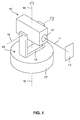
- FIG. 1 shows an optical measuring device 10 for measuring target objects in a schematic representation.
- a laser beam 11 is generated, which emerges via a decoupling opening 12 from the measuring device 10 and is aligned with a target object 13 .
- the first and second image 51, 53 of the target object 13 before the evaluation for the inventive method with known image processing methods, such as white image or flat-field correction, edited.
- image processing methods such as white image or flat-field correction
- a laser beam 55 and a surrounding area 56 are identified in a step S09 by means of the evaluation element 36.
- known methods of object recognition are used.
Landscapes
- Engineering & Computer Science (AREA)
- Physics & Mathematics (AREA)
- General Physics & Mathematics (AREA)
- Radar, Positioning & Navigation (AREA)
- Remote Sensing (AREA)
- Computer Networks & Wireless Communication (AREA)
- Manufacturing & Machinery (AREA)
- Length Measuring Devices By Optical Means (AREA)
- Measurement Of Optical Distance (AREA)
- Optical Radar Systems And Details Thereof (AREA)
- Studio Devices (AREA)
Abstract
Verfahren zum Kalibrieren eines Messgerätes (10) mittels eines Zielobjektes (13), bei dem vor der Kalibrierung des Messgerätes (10) die Eignung des Zielobjektes (13) anhand mehrerer Bewertungskriterien geprüft wird. Die Kalibrierung des Messgerätes (10) mittels des Zielobjektes (13) wird nur durchgeführt, wenn das Zielobjekt (13) alle Bewertungskriterien erfüllt. Zur Bewertung des Zielobjektes (13) werden mit einer Kameraeinrichtung ein Bild des Zielobjektes (13) ohne Laserstrahl (11) und ein Bild des Zielobjektes (13) mit Laserstrahl (11) aufgenommen und durch Bildverarbeitungs- und Objekterkennungsverfahren ausgewertet.Method for calibrating a measuring device (10) by means of a target object (13), in which the suitability of the target object (13) is checked on the basis of several evaluation criteria before the calibration of the measuring device (10). The calibration of the measuring device (10) by means of the target object (13) is only carried out if the target object (13) fulfills all the evaluation criteria. To evaluate the target object (13), a picture of the target object (13) without a laser beam (11) and an image of the target object (13) with a laser beam (11) are taken with a camera device and evaluated by image processing and object recognition methods.
Description
Die vorliegende Erfindung betrifft ein Verfahren zum Kalibrieren eines Messgerätes mittels eines Zielobjektes gemäß dem Oberbegriff des Anspruchs 1 sowie ein Messgerät zur Durchführung eines derartigen Verfahrens gemäß dem Oberbegriff des Anspruchs 6.The present invention relates to a method for calibrating a measuring device by means of a target object according to the preamble of claim 1 and to a measuring device for carrying out such a method according to the preamble of claim 6.
Unter dem Begriff "Kalibrieren" wird ein Messverfahren definiert, bei dem die Abweichung zwischen einer ersten und zweiten Größe festgestellt und dokumentiert wird. Die ermittelte Abweichung wird bei der anschließenden Benutzung des Messgerätes zur Korrektur berücksichtigt.The term "calibration" defines a measuring method in which the deviation between a first and second size is detected and documented. The determined deviation is taken into account during the subsequent use of the measuring device for correction.
Optische Messgeräte umfassen eine oder mehrere Lasermesseinrichtungen, eine Kameraeinrichtung und eine Kontrolleinrichtung, wobei die Lasermesseinrichtungen bspw. als Winkelmesseinrichtung oder Distanzmesseinrichtung ausgebildet sind. Mit Hilfe optischer Messgeräte können Winkel, Entfernungen und Positionen von Zielobjekten bestimmt werden. Unter dem Begriff "Zielobjekt" werden sämtliche Objekte zusammengefasst, die einen auftreffenden Laserstrahl reflektieren, streuen oder reflektieren und streuen.Optical measuring devices comprise one or more laser measuring devices, a camera device and a control device, wherein the laser measuring devices are designed, for example, as an angle measuring device or distance measuring device. With the aid of optical measuring devices, angles, distances and positions of target objects can be determined. The term "target object" includes all objects which reflect, scatter or reflect and scatter an incident laser beam.
Beim Vermessen von natürlichen Zielen, wie beispielsweise Ecken oder Kanten von Gebäuden, hängt die Messgenauigkeit der Messgeräte wesentlich davon ab, wie genau die Zielachse der Kameraeinrichtung und die Messachse der Lasermesseinrichtung koaxial angeordnet sind. Die Abweichungen von der Koaxialität der Mess- und Zielachse nehmen zu, je mehr bewegliche Optikkomponenten ein Messgerät aufweist. Kameraeinrichtungen mit Zoomobjektiven besitzen eine hohe optische Auflösung, weisen aber gleichzeitig eine instabile Zielachse auf.When measuring natural targets, such as corners or edges of buildings, the measurement accuracy of the measuring equipment depends essentially on how exactly the target axis of the camera device and the measuring axis of the laser measuring device are arranged coaxially. The deviations from the coaxiality of the measuring and target axis increase, the more movable optical components a measuring device has. Camera devices with zoom lenses have a high optical resolution, but at the same time have an unstable target axis.
Bekannt ist, die Koaxialität der Mess- und Zielachse eines Messgerätes durch den Bediener zu prüfen und, falls erforderlich, manuell über Justierelemente zu korrigieren. Die manuelle Justierung durch den Bediener ist aufwändig.It is known to check the coaxiality of the measuring and target axis of a measuring device by the operator and, if necessary, to correct it manually via adjusting elements. Manual adjustment by the operator is expensive.
Die Aufgabe der vorliegenden Erfindung besteht in der Entwicklung eines automatischen Verfahrens zum Kalibrieren eines Messgerätes, das ohne Eingriff eines Bedieners durchgeführt werden kann. Außerdem soll ein entsprechendes Messgerät zur Durchführung des Kalibrierverfahrens entwickelt werden.The object of the present invention is to develop an automatic method for calibrating a measuring device, which can be carried out without intervention of an operator. In addition, a corresponding measuring device for carrying out the calibration process to be developed.
Diese Aufgabe wird bei dem eingangs genannten Verfahren zum Kalibrieren eines Messgerätes erfindungsgemäß durch die Merkmale des unabhängigen Anspruchs gelöst. Vorteilhafte Weiterbildungen sind in den abhängigen Ansprüchen angegeben.This object is achieved in the method for calibrating a measuring device according to the invention by the features of the independent claim. Advantageous developments are specified in the dependent claims.
Erfindungsgemäß umfasst das Verfahren zum Kalibrieren eines Messgerätes, das eine Lasermesseinrichtung, die einen Laserstrahl entlang einer Messachse aussendet, eine Kameraeinrichtung mit einer Zielachse und eine Kontrolleinrichtung aufweist, die folgenden Schritte:
- ■ Aufnehmen eines ersten Bildes eines Zielobjektes bei ausgeschaltetem Laserstrahl mittels der Kameraeinrichtung,
- ■ Festlegen eines Bildausschnittes um die in der Kontrolleinrichtung gespeicherte Position der Zielachse im ersten Bild des Zielobjektes,
- ■ Bestimmen eines ersten Kontrastes zwischen dem dunkelsten Bildbereich des Bildausschnittes und dem hellsten Bildbereich des Bildausschnittes,
- ■ Vergleichen des ersten Kontrastes mit einem in der Kontrolleinrichtung gespeicherten ersten Grenzwert,
- ■ Aufnehmen eines zweiten Bildes des Zielobjektes bei eingeschaltetem Laserstrahl mittels der Kameraeinrichtung, wenn der erste Kontrast den ersten Grenzwert nicht überschreitet,
- ■ Bestimmen eines Differenzbildes zwischen dem ersten und zweiten Bild des Zielobjektes,
- ■ Identifizieren eines Laserstrahles und eines Umgebungsbereiches im Differenzbild des Zielobjektes,
- ■ Bestimmen eines zweiten Kontrastes zwischen dem hellsten Bildbereich des Umgebungsbereiches und dem dunkelsten Bildbereich des Laserstrahles,
- ■ Vergleichen des zweiten Kontrastes mit einem in der Kontrolleinrichtung gespeicherten zweiten Grenzwert,
- ■ Bestimmen eines Schwerpunktes des Laserstrahles und der Schwerpunktkoordinaten, wenn der zweite Kontrast den zweiten Grenzwert nicht unterschreitet, und
- ■ Speichern der Schwerpunktkoordinaten des Laserstrahles als neue Position der Zielachse in der Kontrolleinrichtung.
- Recording a first image of a target object with the laser beam switched off by means of the camera device,
- Defining an image section around the position of the target axis stored in the control device in the first image of the target object,
- Determining a first contrast between the darkest image area of the image section and the brightest image area of the image section,
- ■ comparing the first contrast with a first limit value stored in the control device,
- Recording a second image of the target object with the laser beam switched on by means of the camera device if the first contrast does not exceed the first limit value,
- Determining a difference image between the first and second images of the target object,
- Identifying a laser beam and a surrounding area in the difference image of the target object,
- Determining a second contrast between the brightest image area of the surrounding area and the darkest image area of the laser beam,
- ■ comparing the second contrast with a second limit value stored in the control device,
- ■ Determining a center of gravity of the laser beam and the center of gravity coordinates, if the second contrast does not fall below the second limit, and
- ■ Save the center of gravity coordinates of the laser beam as a new position of the target axis in the control device.
Das erfindungsgemäße Verfahren hat den Vorteil, dass die Kalibrierung des Messgerätes mittels des Zielobjektes nur durchgeführt wird, wenn das Zielobjekt zwei Bewertungskriterien erfüllt. Als erstes Bewertungskriterium wird die Gleichmäßigkeit in der Helligkeit des Zielobjektes anhand des ersten Kontrastes geprüft und als zweites Bewertungskriterium wird der Unterschied in der Helligkeit zwischen dem identifizierten Laserstrahl und dem umgebenden Zielobjekt anhand des zweiten Kontrastes geprüft.The method according to the invention has the advantage that the calibration of the measuring device by means of the target object is only carried out if the target object fulfills two evaluation criteria. As the first evaluation criterion, the uniformity in the brightness of the target object is checked on the basis of the first contrast, and as a second evaluation criterion, the difference in brightness between the identified laser beam and the surrounding target object is checked on the basis of the second contrast.
Die Auswertung der Bilder des Zielobjektes erfolgt mit Hilfe bekannter Bildverarbeitungs- und Objekterkennungsverfahren. Unter dem Begriff "Objekterkennung" werden Verfahren zum Identifizieren eines bekannten Objektes innerhalb eines Objektraumes mittels optischer, akustischer oder anderer physikalischer Erkennungsverfahren zusammengefasst.The evaluation of the images of the target object takes place with the aid of known image processing and object recognition methods. The term "object recognition" encompasses methods for identifying a known object within an object space by means of optical, acoustic or other physical recognition methods.
Der Kontrast ist ein Unterscheidungsmerkmal für den Helligkeitsverlauf eines Bildes oder den Helligkeitsunterschied zwischen zwei Bildbereichen. Als physikalische Messgröße für die Helligkeit wird die Lichtstärke, die in Candela gemessen wird, oder eine vergleichbare Messgröße verwendet. Für jeden Pixel des Bildsensors liefert die Kameraeinrichtung einen Pixelwert. Als Bildbereich wird die kleinste Einheit der Bilder des Zielobjektes bezeichnet, die für die Bewertung des Zielobjektes im Rahmen des erfindungsgemäßen Verfahrens herangezogen wird. Der Bildbereich kann ein einzelnes Pixel sein oder mehrere benachbarte Pixel umfassen. Wenn die Bildbereiche jeweils ein Pixel umfassen, werden die Pixelwerte der einzelnen Pixel bei der Berechnung des Kontrastes verglichen; bei Bildbereichen mit mehreren Pixeln werden die Pixelwerte zu einem Messwert gemittelt und die gemittelten Messwerte anschließend verglichen.The contrast is a distinguishing feature for the brightness of an image or the brightness difference between two image areas. As a physical measure of the brightness, the light intensity, which is measured in candela, or a comparable measurand used. For each pixel of the image sensor, the camera device provides a pixel value. The image area is the smallest unit of the images of the target object, which is used for the evaluation of the target object in the context of the method according to the invention. The image area may be a single pixel or may include multiple adjacent pixels. If the image areas each comprise one pixel, the pixel values of the individual pixels are compared in the calculation of the contrast; For image areas with several pixels, the pixel values are averaged into a measured value and the averaged measured values are then compared.
Der erste Kontrast ist durch die Differenz aus 1 und dem Verhältnis der Messwerte zwischen dem dunkelsten Bildbereich (minimaler Messwert) und dem hellsten Bildbereich (maximaler Messwert) des Bildausschnittes definiert und wird als Prozentwert angegeben. Um den Messfehler bei der Kalibrierung zu begrenzen, sollte das Zielobjekt eine möglichst gleichmäßige Oberflächenstruktur aufweisen, die sich im Bild des Zielobjektes als gleichmäßige Helligkeit darstellt. Die Abweichung der Bildbereiche zum hellsten Bildbereich des Bildausschnittes muss kleiner als ein erster Grenzwert sein. Der erste Grenzwert beträgt beispielsweise 5 %, d.h. alle Bildbereiche des Bildausschnittes weisen eine Abweichung kleiner als 5 % zum hellsten Bildbereich auf. Der erste Grenzwert ist vorab festgelegt und in der Kontrolleinrichtung gespeichert.The first contrast is defined by the difference between 1 and the ratio of the measured values between the darkest image area (minimum measured value) and the brightest image area (maximum measured value) of the image section and is given as a percentage value. In order to limit the measurement error during the calibration, the target object should have as uniform a surface structure as possible, which presents itself as a uniform brightness in the image of the target object. The deviation of the image areas from the brightest image area of the image section must be smaller than a first limit value. The first limit is, for example, 5%, i. All image areas of the image section have a deviation of less than 5% to the brightest image area. The first limit is predetermined and stored in the controller.
Das Kalibrierverfahren wird nach dem Vergleich des ersten Kontrastes mit dem ersten Grenzwert abgebrochen, wenn der erste Kontrast den ersten Grenzwert überschreitet; das Kalibrierverfahren wird nur fortgesetzt, wenn der erste Kontrast den ersten Grenzwert unterschreitet bzw. nicht überschreitet. Wenn der erste Kontrast des Bildausschnittes den ersten Grenzwert überschreitet, ist das Zielobjekt für die Kalibrierung des Messgerätes ungeeignet und das Kalibrierverfahren wird abgebrochen. Das Messgerät kann von der Kontrolleinrichtung aus dem Kalibriermodus in einen Messmodus umgeschaltet werden; als Position der Zielachse wird für weitere Messungen die in der Kontrolleinrichtung gespeicherte Position verwendet.The calibration procedure is aborted after comparing the first contrast with the first threshold when the first contrast exceeds the first threshold; the calibration procedure is only continued if the first contrast does not exceed or does not exceed the first limit value. If the first contrast of the image section is the first Exceeds the limit value, the target object is unsuitable for the calibration of the measuring device and the calibration procedure is aborted. The measuring device can be switched from the control device from the calibration mode to a measuring mode; as the position of the target axis, the position stored in the control device is used for further measurements.
Der zweite Kontrast ist durch die Differenz aus 1 und dem Verhältnis der Messwerte zwischen dem hellsten Bildbereich (maximaler Messwert) des Umgebungsbereiches und dem dunkelsten Bildbereich (minimaler Messwert) des Laserstrahles definiert und wird als Prozentwert angegeben. Um den Messfehler bei der Kalibrierung zu begrenzen, sollte der Laserstrahl eine höhere Helligkeit gegenüber dem Umgebungsbereich aufweisen. Der Unterschied der Bildbereiche des Laserstrahles zu den Bildbereichen des Umgebungsbereiches muss grösser als ein zweiter Grenzwert sein. Der zweite Grenzwert beträgt beispielsweise 10 %. d.h. alle Bildbereiche des Laserstrahles weisen eine um mindestens 10 % höhere Lichtstärke als die Bildbereiche des Umgebungsbereiches auf. Der zweite Grenzwert ist vorab festgelegt und in der Kontrolleinrichtung gespeichert.The second contrast is defined by the difference of 1 and the ratio of the readings between the brightest image area (maximum reading) of the surrounding area and the darkest picture area (minimum reading) of the laser beam and is expressed as a percentage. To limit the measurement error during calibration, the laser beam should have a higher brightness compared to the surrounding area. The difference of the image areas of the laser beam to the image areas of the surrounding area must be greater than a second limit value. The second limit is for example 10%. i.e. All image areas of the laser beam have at least 10% higher light intensity than the image areas of the surrounding area. The second limit is predetermined and stored in the controller.
Das Kalibrierverfahren wird nach dem Vergleich des zweiten Kontrastes mit dem zweiten Grenzwert abgebrochen, wenn der zweite Kontrast den zweiten Grenzwert unterschreitet; das Kalibrierverfahren wird nur fortgesetzt, wenn der zweite Kontrast den zweiten Grenzwert überschreitet bzw. nicht unterschreitet. Wenn der zweite Kontrast den zweiten Grenzwert unterschreitet, ist das Zielobjekt für die Kalibrierung des Messgerätes ungeeignet und das Kalibrierverfahren wird abgebrochen. Das Messgerät kann von der Kontrolleinrichtung aus dem Kalibriermodus in einen Messmodus umgeschaltet werden; als Position der Zielachse wird für weitere Messungen die in der Kontrolleinrichtung gespeicherte Position verwendet.The calibration procedure is aborted after the comparison of the second contrast with the second threshold when the second contrast is less than the second threshold; the calibration procedure is only continued if the second contrast exceeds or does not fall below the second limit. If the second contrast falls below the second threshold, the target is unsuitable for the calibration of the meter and the calibration procedure is aborted. The measuring device can be switched from the control device from the calibration mode to a measuring mode; as the position of the target axis, the position stored in the control device is used for further measurements.
Eine bevorzugte Weiterentwicklung des erfindungsgemäßen Verfahrens zum Kalibrieren eines Messgerätes ist gekennzeichnet durch die zusätzlichen Schritte:
- ■ Ausführen einer Distanzmessung zum Zielobjekt und
- ■ Vergleichen der gemessenen Distanz mit einem in der Kontrolleinrichtung gespeicherten Distanzbereich.
- ■ Performing a distance measurement to the target object and
- ■ Compare the measured distance with a distance range stored in the control device.
Die Distanz des Messgerätes zum Zielobjekt ist ein weiteres Bewertungskriterium, das die Qualität eines Zielobjektes für die Kalibrierung eines Messgerätes bewertet. Die Distanzmessung und der Vergleich mit dem in der Kontrolleinrichtung gespeicherten Distanzbereich können ausgeführt werden, bevor die Kameraeinrichtung das erste Bild des Zielobjektes aufnimmt, nachdem das erste Bewertungskriterium geprüft wurde oder nachdem das zweite Bewertungskriterium geprüft wurde.The distance of the measuring device to the target object is another evaluation criterion that evaluates the quality of a target object for the calibration of a measuring device. The distance measurement and the comparison with the distance range stored in the control device may be carried out before the camera device takes the first image of the target object after the first evaluation criterion has been checked or after the second evaluation criterion has been checked.
Das Kalibrierverfahren wird besonders bevorzugt abgebrochen, wenn die gemessene Distanz des Messgerätes zum Zielobjekt außerhalb des gespeicherten Distanzbereiches liegt; das Kalibrierverfahren wird nur fortgesetzt, wenn die gemessene Distanz innerhalb des gespeicherten Distanzbereiches liegt. Um den Messfehler bei der Kalibrierung zu begrenzen, sollte das Zielobjekt innerhalb eines festgelegten Distanzbereiches angeordnet sein. Wenn die Distanz außerhalb des Distanzbereiches liegt, ist das Zielobjekt für die Kalibrierung des Messgerätes ungeeignet und das Kalibrierverfahren wird abgebrochen. Für Distanzen, die oberhalb des Distanzbereiches liegen, besteht die Gefahr, dass die Lichtstärke der Bildbereiche innerhalb des Laserstrahles zu gering ist. Das Messgerät kann von der Kontrolleinrichtung aus dem Kalibriermodus in einen Messmodus umgeschaltet werden; als Position der Zielachse wird für weitere Messungen die in der Kontrolleinrichtung gespeicherte Position verwendet.The calibration method is particularly preferably terminated if the measured distance of the measuring device to the target object lies outside the stored distance range; the calibration procedure will only continue if the measured distance is within the stored distance range. In order to limit the measurement error during the calibration, the target object should be arranged within a defined distance range. If the distance is outside of the distance range, the target object is unsuitable for the calibration of the measuring device and the calibration procedure is aborted. For distances that are above the distance range, there is a risk that the light intensity of the image areas within the laser beam is too low. The measuring device can be switched from the control device from the calibration mode to a measuring mode; as the position of the target axis, the position stored in the control device is used for further measurements.
Zur Ausführung des erfindungsgemäßen Verfahrens zum Kalibrieren eines Messgerätes umfasst das Messgerät:
- ■ eine Lasermesseinrichtung, die einen Laserstrahl entlang einer Messachse aussendet,
- ■ eine Kameraeinrichtung mit einer Zielachse und
- ■ eine Kontrolleinrichtung mit einem Steuerelement zur Steuerung der Lasereinrichtung und der Kameraeinrichtung, einem Auswerteelement und einem Speicherelement.
- ■ a laser measuring device which emits a laser beam along a measuring axis,
- ■ a camera device with a target axis and
- ■ a control device with a control element for controlling the laser device and the camera device, an evaluation element and a storage element.
In einer bevorzugten Weiterentwicklung des Messgerätes weist die Kameraeinrichtung eine Kameraoptik auf, die zwischen einer ersten und zweiten Brennweite verstellbar ist, wobei im Speicherelement für die erste Brennweite der Kameraoptik eine erste Position der Zielachse und für die zweite Brennweite der Kameraoptik eine zweite Position der Zielachse gespeichert ist. Bei einer Kameraoptik mit beweglichen Optiken ändert sich die Ausrichtung der Zielachse durch die Bewegung der Optiken. Die Messgenauigkeit eines Messgerätes kann verbessert werden, wenn für verschiedene Brennweiten der Kameraoptik die jeweilige Position der Zielachse gespeichert ist.In a preferred refinement of the measuring device, the camera device has a camera optics which can be adjusted between a first and second focal length, wherein a first position of the target axis is stored in the memory element for the first focal length of the camera optics and a second position of the target axis for the second focal length of the camera optics is. In a camera optics with movable optics, the alignment of the target axis changes by the movement of the optics. The measuring accuracy of a measuring device can be improved if the respective position of the target axis is stored for different focal lengths of the camera optics.
Besonders bevorzugt ist die Kameraoptik zwischen mehr als zwei Brennweiten schaltbar, wobei im Speicherelement für jede Brennweite der Kameraoptik eine Position der Zielachse gespeichert ist. Die Instabilität der Kameraoptik und damit die Instabilität der Zielachse nehmen zu, je grösser bei beweglichen Optiken der mechanische Verstellbereich ist. Die Messgenauigkeit eines Messgerätes kann verbessert werden, wenn für verschiedene Brennweiten die jeweilige Position der Zielachse gespeichert ist.Particularly preferably, the camera optics can be switched between more than two focal lengths, wherein a position of the target axis is stored in the memory element for each focal length of the camera optics. The instability of the camera optics and thus the instability of the target axis increase, the greater is the mechanical adjustment range for moving optics. The measuring accuracy of a measuring device can be improved if the respective position of the target axis is stored for different focal lengths.
Ausführungsbeispiele der Erfindung werden nachfolgend anhand der Zeichnung beschrieben. Diese soll die Ausführungsbeispiele nicht notwendigerweise maßstäblich darstellen, vielmehr ist die Zeichnung, wo zur Erläuterung dienlich, in schematischer und/oder leicht verzerrter Form ausgeführt. Im Hinblick auf Ergänzungen der aus der Zeichnung unmittelbar erkennbaren Lehren wird auf den einschlägigen Stand der Technik verwiesen. Dabei ist zu berücksichtigen, dass vielfältige Modifikationen und Änderungen betreffend die Form und das Detail einer Ausführungsform vorgenommen werden können, ohne von der allgemeinen Idee der Erfindung abzuweichen. Die in der Beschreibung, der Zeichnung sowie den Ansprüchen offenbarten Merkmale der Erfindung können sowohl einzeln für sich als auch in beliebiger Kombination für die Weiterbildung der Erfindung wesentlich sein. Zudem fallen in den Rahmen der Erfindung alle Kombinationen aus zumindest zwei der in der Beschreibung, der Zeichnung und/oder den Ansprüchen offenbarten Merkmale. Die allgemeine Idee der Erfindung ist nicht beschränkt auf die exakte Form oder das Detail der im Folgenden gezeigten und beschriebenen bevorzugten Ausführungsform oder beschränkt auf einen Gegenstand, der eingeschränkt wäre im Vergleich zu dem in den Ansprüchen beanspruchten Gegenstand. Bei gegebenen Bemessungsbereichen sollen auch innerhalb der genannten Grenzen liegende Werte als Grenzwerte offenbart und beliebig einsetzbar und beanspruchbar sein. Der Einfachheit halber sind nachfolgend für identische oder ähnliche Teile oder Teile mit identischer oder ähnlicher Funktion gleiche Bezugszeichen verwendet.Embodiments of the invention are described below with reference to the drawing. This is not necessarily to scale the embodiments, but the drawing, where appropriate for explanation, executed in a schematic and / or slightly distorted form. With regard to additions to the teachings directly recognizable from the drawing reference is made to the relevant prior art. It should be noted that various modifications and changes may be made in the form and detail of an embodiment without departing from the general idea of the invention. The disclosed in the description, the drawings and the claims features of the invention may be essential both individually and in any combination for the development of the invention. In addition, all combinations of at least two of the features disclosed in the description, the drawings and / or the claims fall within the scope of the invention. The general idea of the invention is not limited to the exact form or detail of the preferred embodiment shown and described below or limited to an article that would be limited in comparison with the subject matter claimed in the claims. For given design ranges, values lying within the specified limits should also be disclosed as limit values and be arbitrarily usable and claimable. For simplicity, the same reference numerals are used below for identical or similar parts or parts with identical or similar function.
Es zeigen:
- FIG. 1
- ein Messgerät zur Vermessung von Zielobjekten in einer schematischen Darstellung;
- FIG. 2
- das Messgerät der
FIG. 1 , das nach dem erfindungsgemäßen Verfahren zur Kalibrierung kalibrierbar ist, mit einer Distanzmesseinrichtung, einer Kameraeinrichtung und einer Kontrolleinrichtung; - FIG. 3
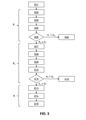
- eine Ausführungsvariante des erfindungsgemäßen Verfahrens zur Kalibrierung eines Messgerätes in einem Ablaufdiagramm;
- FIGN. 4A-C
- ein erstes Bild eines Zielobjektes bei ausgeschaltetem Laserstrahl (
FIG. 4A ), ein zweites Bild des Zielobjektes bei eingeschaltetem Laserstrahl (FIG. 4B ) und ein Differenzbild zwischen dem ersten und zweiten Bild (FIG. 4C ); und - FIG. 5
- eine weitere Ausführungsvariante des erfindungsgemäßen Verfahrens zur Kalibrierung eines Messgerätes in einem Ablaufdiagramm.
- FIG. 1
- a measuring device for measuring target objects in a schematic representation;
- FIG. 2
- the meter of the
FIG. 1 , which can be calibrated by the method according to the invention for calibration, with a distance measuring device, a camera device and a control device; - FIG. 3
- an embodiment of the method according to the invention for calibrating a measuring device in a flowchart;
- FIGS. 4A-C
- a first image of a target object with the laser beam switched off (
FIG. 4A ), a second image of the target object when the laser beam is switched on (FIG. 4B ) and a difference image between the first and second images (FIG. 4C ); and - FIG. 5
- a further embodiment of the method according to the invention for calibrating a measuring device in a flowchart.
Das Messgerät 10 ist mittels einer Verstelleinrichtung 14 in mehreren Richtungen verstellbar, so dass der Laserstrahl 11 auf verschiedene Zielobjekte, die sich beispielsweise in der Höhe und/oder der Winkelausrichtung unterscheiden können, ausgerichtet werden kann. Das Messgerät 10 ist in einem U-förmigen Lagerelement 15 gelagert und relativ zum Lagerelement 15 um eine horizontale Kippachse 16 verstellbar. Das Lagerelement 15 ist auf einem Stativteller 17 angeordnet und relativ zum Stativteller 17 um eine vertikale Drehachse 18 drehbar, so dass Zielobjekte in allen Winkellagen angezielt werden können. Das Stativ, auf dem das Messgerät 10 befestigt ist, ist üblicherweise so ausgerichtet, dass die Kippachse 16 senkrecht zum Lot und die Drehachse 18 parallel zum Lot angeordnet sind.The measuring
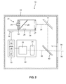
Die Lasermesseinrichtung 21 ist als Distanzmesseinrichtung mit einer koaxialen Anordnung der elektro-optischen Komponenten (Strahlquelle und Detektor) ausgebildet. Distanzmesseinrichtungen mit einer koaxialen Anordnung der elektro-optischen Komponenten besitzen gegenüber paraaxialen Anordnungen, bei denen die optischen Achsen der elektro-optischen Komponenten parallel versetzt verlaufen, den Vorteil der Parallaxefreiheit und sind daher für die Anwendung im Messgerät 10 besser geeignet. Die Distanzmesseinrichtung 21 umfasst eine als Strahlquelle 25 ausgebildete erste elektro-optische Komponente, eine als Detektor 26 ausgebildete zweite elektro-optische Komponente, eine Strahlformungsoptik 27, eine Strahlteilungsoptik 28, einen Optikträger 29, eine Leiterplatte 31 und ein Kontrollelement 32. Für den Aufbau eines Messgerätes 10 mit einer hohen Messgenauigkeit eignen sich besonders Lasermesseinrichtungen 21, die eine hohe Stabilität aufweisen. Eine stabile Distanzmesseinrichtung mit einer koaxialen Anordnung der elektro-optischen Komponenten ist in
Die Strahlquelle 25 ist als Laserdiode ausgebildet, die einen Laserstrahl im sichtbaren oder infraroten Spektrum erzeugt. Der Detektor 26 ist als Fotodiode ausgebildet, wobei die Eigenschaften der Fotodiode 26 an die Laserdiode 25 angepasst sind. Das Kontrollelement 32 ist mit der Strahlquelle 25 und dem Detektor 26 verbunden und bestimmt aus einer Zeitdifferenz zwischen einem Referenzstrahl und einem vom Detektor 26 erfassten Empfangsstrahl die Distanz zum Zielobjekt 13. Die Strahlformungsoptik 27 ist als Linse ausgebildet, die sowohl den ausgesandten Laserstrahl als auch den vom Zielobjekt 13 reflektierten und/oder gestreuten Empfangsstrahl formt. Mit Hilfe der Strahlteilungsoptik 28 wird der von der Strahlquelle 25 kommende Laserstrahl vom reflektierten und/oder gestreuten Empfangsstrahl räumlich getrennt.The
Die Kameraeinrichtung 22 umfasst einen Bildsensor 33 und eine Kameraoptik 34. Als Bildsensor eignet sich jedes lichtempfindliche elektronische Bauelement, mit dem von einem Zielobjekt ein digitales Bild erstellen werden kann. Als Bildsensoren werden beispielsweise CCD-Sensoren, CID-Sensoren oder CMOS-Sensoren verwendet. Bildsensoren bestehen aus einem Array lichtempfindlicher Elemente; die kleinste Einheit des Bildsensors wird als Pixel bezeichnet und die Kameraeinrichtung liefert für jeden Pixel einen Messwert, der als Pixelwert bezeichnet wird. Jeder Pixel des Bildsensors entspricht einem Bildbereich im Bild des Zielobjektes. Je grösser die Fläche der Pixel ist, desto höher ist die Lichtempfindlichkeit und desto kleiner ist aber die Bildauflösung. Die Kameraoptik 34 kann, wie in
Die Kontrolleinrichtung 23 umfasst ein Steuerelement 35 zur Steuerung der Distanzmesseinrichtung 21 und der Kameraeinrichtung 22, ein Auswerteelement 36 zur Auswertung der Bilder, die von der Kameraeinrichtung 22 aufgenommen wurden, sowie ein Speicherelement 37 zur Speicherung voreingestellter Parameter für das Kalibrierverfahren. Die Steuerung der Kameraeinrichtung 22 und die Auswertung der Bilder erfolgt über die Kontrolleinrichtung 23, die über eine Kommunikationsverbindung mit der Kameraeinrichtung 22 verbunden ist; alternativ kann das Auswerteelement 36 in die Kameraeinrichtung 22 integriert und über eine Kommunikationsverbindung mit der Kontrolleinrichtung 23 verbunden werden. Das Kontrollelement 32 der Distanzmesseinrichtung 21 ist über eine Kommunikationsverbindung mit der Kontrolleinrichtung 23 verbunden. Die Steuerung der elektro-optischen Komponenten 25, 26 und die Berechnung der Distanz erfolgen in dieser Ausführung mittels des Kontrollelementes 32; der Steuerbefehl, eine Distanzmessung auszuführen oder den Laserstrahl 11 als Positionierstrahl auszusenden, wird vom Steuerelement 35 erstellt. Alternativ kann das Kontrollelement 32 in die Kontrolleinrichtung 23 integriert werden.The
Die Distanzmesseinrichtung 21 und die Kameraeinrichtung 22 müssen genau zueinander angeordnet sein, um Messfehler bei der Vermessung zu reduzieren. Als Messachse 38 der Distanzmesseinrichtung 21 ist die optische Achse des Laserstrahles definiert und als Zielachse 39 der Kameraeinrichtung 22 die optische Achse der Kameraoptik 34. Damit die Messachse 38 und die Zielachse 39 koaxial zueinander angeordnet sind, sind im Gerätegehäuse 24 ein erster und zweiter Umlenkspiegel 41, 42 angeordnet, die den Laserstrahl und den Empfangsstrahl zweifach umlenken. Die Umlenkspiegel 41, 42 sind für die Wellenlänge des Laserstrahls und des Empfangsstrahls reflektierend ausgebildet. Der aus der Distanzmesseinrichtung 21 ausgetretene Laserstrahl trifft auf den ersten Umlenkspiegel 41, der den Laserstrahl um 90° umlenkt. Der umgelenkte Laserstrahl trifft auf den zweiten Umlenkspiegel 42, der den Laserstrahl ebenfalls um 90° umlenkt. Die optische Achse 38 des zweifach umgelenkten Laserstrahls verläuft nur im Idealfall koaxial zur optischen Achse 39 der Kameraeinrichtung 22, in der Praxis können die Messachse 38 und Zielachse 39 zueinander verkippt sein.The
Die Position der Zielachse 39 der Kameraeinrichtung 22 wird vom Gerätehersteller gemessen und im Speicherelement 37 als Positionskoordinate XP, YP gespeichert. Wenn in der Kameraeinrichtung 22 eine Kameraoptik 34 mit zwei Brennweiten f1, f2 verwendet wird, können die Positionen der Zielachse 39 für jede Brennweite der Kameraeinrichtung 22 gemessen und als Positionskoordinaten XP1, YP1 für die erste Brennweite f1 und XP2, YP2 für die zweite Brennweite f2 im Speicherelement 37 der Kontrolleinrichtung 23 gespeichert werden. Die, im Speicherelement 37 gespeicherte, Position der Zielachse 39 ist im aktuellen Bild des Zielobjektes, das auf dem Bildsensor 33 dargestellt ist, beispielsweise als Fadenkreuz eingeblendet. Das Fadenkreuz soll dem Bediener ein zielgenaues Positionieren des Laserstrahles erleichtern.The position of the
Nachdem das Messgerät 10 die voreingestellte Anzahl von Messungen durchgeführt hat, schaltet das Steuerelement 35 der Kontrolleinrichtung 23 das Messgerät 10 in einem Schritt S01 in einen Kalibriermodus. Im Kalibriermodus ist die Kameraeinrichtung 22 auf das Zielobjekt 13 ausgerichtet und der Laserstrahl 11 der Distanzmesseinrichtung 21 ist ausgeschaltet.After the measuring
In einem Schritt S02 wird mittels der Kameraeinrichtung 22 ein erstes Bild 51 des Zielobjektes 13 aufgenommen, das in
In einem Schritt S04 bestimmt das Auswerteelement 36 für die Pixel, die innerhalb des Bildausschnittes 52 liegen, die jeweilige Lichtstärke und berechnet einen ersten Kontrast K1 als Differenz aus 1 und dem Verhältnis der Lichtstärken zwischen dem dunkelsten Pixel P1, min des Bildausschnittes 52 und dem hellsten Pixel P1, max des Bildausschnittes 52 nach der Formel K1 = (1 - P1, min / P1, max) * 100 %. Ein erster Kontrast K1 von 100 % entspricht einem maximalen Unterschied in der Lichtstärke, d.h. das dunkelste Pixel P1, min weist keine Lichtstärke auf und das hellste Pixel P1, max eine maximale Lichtstärke. Bei einem ersten Kontrast K1 von 0 % besteht zwischen dem dunkelsten Pixel P1, min und dem hellsten Pixel P1, max kein Unterschied in der Lichtstärke, d.h. alle Pixel des Bildausschnittes 52 weisen die gleiche Lichtstärke auf.In a step S04 , the
In Schritt S04 wird der erste Kontrast K1 aus dem Verhältnis der Lichtstärken zwischen dem dunkelsten Pixel P1, min des Bildausschnittes 52 und dem hellsten Pixel P1, max des Bildausschnittes 52 berechnet. Alternativ können die Pixelwerte mehrerer benachbarter Pixel gemittelt und zur Berechnung des ersten Kontrastes K1 verwendet werden. Als "Bildbereich" wird die kleinste Einheit der Bilder des Zielobjektes bezeichnet, die für die Bewertung des Zielobjektes 13 im Rahmen des erfindungsgemäßen Verfahrens herangezogen wird. Der Bildbereich kann ein einzelnes Pixel sein oder mehrere benachbarte Pixel umfassen, deren Pixelwerte zu einem Messwert gemittelt werden, wobei die Pixelwerte bei der Mittelung gleich oder unterschiedlich gewichtet werden können.In step S04, the first contrast K 1 is calculated from the ratio of the light intensities between the darkest pixel P 1, min of the
Der, in Schritt S04 berechnete, erste Kontrast K1 des Bildausschnittes 52 wird vom Auswerteelement 36 in einem Schritt S05 mit einem ersten Grenzwert G1 verglichen. Um den Messfehler bei der Kalibrierung zu begrenzen, sollte das Zielobjekt 13 eine möglichst gleichmäßige Helligkeit aufweisen. Der erste Grenzwert G1 beträgt beispielsweise 5 %, d.h. alle Pixel des Bildausschnittes 52 weisen eine Abweichung kleiner als 5 % zum hellsten Pixel P1, max auf. Der erste Grenzwert G1 ist vorab festgelegt und im Speicherelement 37 der Kontrolleinrichtung 23 gespeichert. Wenn der erste Kontrast K1 des Bildausschnittes 52 den ersten Grenzwert G1 überschreitet (K1 > G1), ist das Zielobjekt 13 für die Kalibrierung des Messgerätes 10 ungeeignet. Das Messgerät 10 wird vom Steuerelement 35 in einem Schritt S06 aus dem Kalibriermodus in einen Messmodus umgeschaltet.The first contrast K 1 of the
Das erfindungsgemäße Verfahren wird nach Schritt S05 nur fortgesetzt, wenn der erste Kontrast K1 des Bildausschnittes 52 den ersten Grenzwert G1 nicht überschreitet (K1 ≤ G1). In einem Schritt S07 wird mittels der Kameraeinrichtung 22 ein zweites Bild 53 des Zielobjektes 13 bei eingeschaltetem Laserstrahl 11 aufgenommen, das in
Der in Schritt S10 berechnete zweite Kontrast K2 wird in einem Schritt S11 mittels des Auswerteelementes 36 mit einem zweiten Grenzwert G2 verglichen. Um den Messfehler bei der Kalibrierung zu begrenzen, sollte der Laserstrahl 55 eine höhere Helligkeit gegenüber dem Umgebungsbereich 56 aufweisen. Der zweite Grenzwert G2 beträgt beispielsweise 10 %, d.h. alle Pixel des Laserstrahles 55 weisen eine um mindestens 10 % höhere Lichtstärke als die Pixel des Umgebungsbereiches 56 auf. Der zweite Grenzwert G2 ist vorab festgelegt und im Speicherelement 37 der Kontrolleinrichtung 23 gespeichert. Wenn der zweite Kontrast K2 den zweiten Grenzwert G2 unterschreitet (K2 < G2), ist das Zielobjekt 13 für die Kalibrierung des Messgerätes 10 ungeeignet. Das Messgerät 10 wird vom Steuerelement 35 in einem Schritt S12 aus dem Kalibriermodus in einen Messmodus umgeschaltet.The second contrast K 2 calculated in step S10 is compared in step S11 by means of the
Das erfindungsgemäße Verfahren wird nach Schritt S11 nur fortgesetzt, wenn der zweite Kontrast K2 den zweiten Grenzwert G2 nicht unterschreitet (K2 ≥ G2). In einem Schritt S13 wird mittels des Auswerteelementes 36 ein Schwerpunkt 57 des Laserstrahles 55 und die zugehörigen Schwerpunktkoordinaten XS, YS bestimmt. Dazu werden bekannte Methoden der Objekterkennung angewandt. Die Schwerpunktkoordinaten XS, YS des Laserstrahles 55 werden in einem Schritt S14 als neue Position der Zielachse 39 für die Kameraeinrichtung 22 im Speicherelement 37 gespeichert. Das Auswerteelement 36 übermittelt die Schwerpunktkoordinaten XS, YS an das Speicherelement 37, das die Schwerpunktkoordinaten XS, YS als neue Positionskoordinaten XP, YP der Zielachse 39 speichert. Das Messgerät 10 wird vom Steuerelement 35 in einem Schritt S15 aus dem Kalibriermodus in einen Messmodus umgeschaltet.The inventive method is to step S11 only be continued if the second contrast K 2 the second threshold value G2 is not less than (K ≥ 2 G 2). In a step S13 , a center of
Das in
Die Distanz des Messgerätes 10 zum Zielobjekt 13 ist ein drittes Bewertungskriterium, das die Qualität eines Zielobjektes für die Kalibrierung eines Messgerätes bewertet. In einem Schritt S21 erstellt das Steuerelement 35 einen Steuerbefehl für die Distanzmesseinrichtung 21. Die Distanzmesseinrichtung 21 misst in einem Schritt S22 die Distanz d des Messgerätes 10 zum Zielobjekt 13. Die gemessene Distanz d wird in einem Schritt S23 vom Kontrollelement 32 an die Kontrolleinrichtung 23 übermittelt.The distance of the measuring
Die Distanz d wird in einem Schritt S24 mittels des Auswerteelementes 36 mit einem Distanzbereich (D1, D2) verglichen. Um den Messfehler bei der Kalibrierung zu begrenzen, sollte das Zielobjekt 13 innerhalb des Distanzbereiches (D1, D2) angeordnet sein. Für Distanzen, die oberhalb des Distanzbereiches liegen, besteht die Gefahr, dass die Lichtstärke der Pixel innerhalb des Laserstrahles zu gering ist. Der Distanzbereich (D1, D2) ist vorab festgelegt und im Speicherelement 37 der Kontrolleinrichtung 23 gespeichert. Wenn die Distanz d außerhalb des Distanzbereichs liegt (d < D1 oder d > D2), ist das Zielobjekt 13 für die Kalibrierung des Messgerätes 10 ungeeignet. Das Messgerät 10 wird vom Steuerelement 35 in einem Schritt S25 aus dem Kalibriermodus in einen Messmodus umgeschaltet. Das erfindungsgemäße Verfahren wird nach Schritt S24 nur fortgesetzt, wenn die Distanz innerhalb des Distanzbereichs liegt (D1 ≤ d ≤ D2).The distance d is compared in a step S24 by means of the
Die Schritte S21 bis S24 werden als dritter Bewertungsteil B3 zusammengefasst. Die Distanzmessung (Schritte S21 bis S23) und der Vergleich mit dem Distanzmessbereich (Schritt S24) können, wie in
Claims (8)
Priority Applications (6)
| Application Number | Priority Date | Filing Date | Title |
|---|---|---|---|
| EP13178525.5A EP2833159A1 (en) | 2013-07-30 | 2013-07-30 | Method for calibrating a measuring device |
| EP14744366.7A EP3028063B1 (en) | 2013-07-30 | 2014-07-29 | Method for calibrating a measuring device |
| PCT/EP2014/066303 WO2015014852A1 (en) | 2013-07-30 | 2014-07-29 | Method for calibrating a measuring device |
| US14/908,435 US10228246B2 (en) | 2013-07-30 | 2014-07-29 | Method for calibrating a measurement device |
| JP2016530498A JP6174801B2 (en) | 2013-07-30 | 2014-07-29 | Method for calibrating a surveying instrument |
| CN201480046612.2A CN105474037B (en) | 2013-07-30 | 2014-07-29 | Method for calibration measurement equipment |
Applications Claiming Priority (1)
| Application Number | Priority Date | Filing Date | Title |
|---|---|---|---|
| EP13178525.5A EP2833159A1 (en) | 2013-07-30 | 2013-07-30 | Method for calibrating a measuring device |
Publications (1)
| Publication Number | Publication Date |
|---|---|
| EP2833159A1 true EP2833159A1 (en) | 2015-02-04 |
Family
ID=48914076
Family Applications (2)
| Application Number | Title | Priority Date | Filing Date |
|---|---|---|---|
| EP13178525.5A Withdrawn EP2833159A1 (en) | 2013-07-30 | 2013-07-30 | Method for calibrating a measuring device |
| EP14744366.7A Active EP3028063B1 (en) | 2013-07-30 | 2014-07-29 | Method for calibrating a measuring device |
Family Applications After (1)
| Application Number | Title | Priority Date | Filing Date |
|---|---|---|---|
| EP14744366.7A Active EP3028063B1 (en) | 2013-07-30 | 2014-07-29 | Method for calibrating a measuring device |
Country Status (5)
| Country | Link |
|---|---|
| US (1) | US10228246B2 (en) |
| EP (2) | EP2833159A1 (en) |
| JP (1) | JP6174801B2 (en) |
| CN (1) | CN105474037B (en) |
| WO (1) | WO2015014852A1 (en) |
Cited By (4)
| Publication number | Priority date | Publication date | Assignee | Title |
|---|---|---|---|---|
| EP3173739A1 (en) * | 2015-11-30 | 2017-05-31 | HILTI Aktiengesellschaft | Method for controlling and/or calibrating a vertical axis of a rotation laser |
| EP3173738A1 (en) * | 2015-11-30 | 2017-05-31 | HILTI Aktiengesellschaft | Method for checking a rotation laser for cone errors |
| EP3173741A1 (en) * | 2015-11-30 | 2017-05-31 | HILTI Aktiengesellschaft | Method for controlling and/or calibrating a horizontal axis of a rotation laser |
| DE102020204536A1 (en) | 2020-04-08 | 2021-10-14 | Prüftechnik Dieter Busch GmbH | Laser device and method for adjusting a laser device |
Families Citing this family (7)
| Publication number | Priority date | Publication date | Assignee | Title |
|---|---|---|---|---|
| DE102012223929A1 (en) * | 2012-12-20 | 2014-06-26 | Hilti Aktiengesellschaft | Method and device for determining the two-dimensional location coordinates of a target object |
| DE102017211038A1 (en) * | 2017-06-29 | 2019-01-03 | Robert Bosch Gmbh | Method for adjusting a camera |
| CN107506687B (en) * | 2017-07-17 | 2020-01-21 | Oppo广东移动通信有限公司 | Living body detection method and related product |
| EP3540374B1 (en) | 2018-03-15 | 2021-05-05 | Leica Geosystems AG | Total station with a calibration functionality for instrument errors |
| KR200491661Y1 (en) * | 2019-09-30 | 2020-05-14 | (주)이즈미디어 | Performance validation device for tof camera |
| KR200491660Y1 (en) * | 2019-09-30 | 2020-05-13 | (주)이즈미디어 | Calibration device for tof camera |
| DE102020130481A1 (en) | 2020-11-18 | 2022-05-19 | Daimler Ag | Method and device for detecting contamination on a viewing window of a lidar |
Citations (5)
| Publication number | Priority date | Publication date | Assignee | Title |
|---|---|---|---|---|
| DE102007003586A1 (en) * | 2006-02-09 | 2007-08-16 | Sokkia Co. Ltd., Atsugi | Automatic collimation device for a surveying device |
| EP2348331A1 (en) * | 2010-01-21 | 2011-07-27 | Sick Ag | Optoelectronic sensor for detecting object edges |
| EP2523017A1 (en) * | 2011-05-13 | 2012-11-14 | Hexagon Technology Center GmbH | Calibration method for a device with scan functionality |
| EP2527867A1 (en) | 2011-05-26 | 2012-11-28 | HILTI Aktiengesellschaft | Measuring device for distance measuring |
| EP2527866A1 (en) | 2011-05-26 | 2012-11-28 | HILTI Aktiengesellschaft | Measuring device for distance measuring |
Family Cites Families (6)
| Publication number | Priority date | Publication date | Assignee | Title |
|---|---|---|---|---|
| JPS62100606A (en) * | 1985-10-28 | 1987-05-11 | Nec Corp | Measuring method of degree of parallel of optical axis |
| JP3621123B2 (en) * | 1993-12-28 | 2005-02-16 | 株式会社トプコン | Surveying instrument |
| JP4123787B2 (en) * | 2002-02-07 | 2008-07-23 | トヨタ自動車株式会社 | Vehicle driving support device and vehicle driving support system |
| JP5028164B2 (en) * | 2006-07-03 | 2012-09-19 | タイワン インスツルメント カンパニー リミテッド | Surveying instrument |
| JP5385356B2 (en) * | 2011-10-21 | 2014-01-08 | 株式会社片岡製作所 | Laser processing machine |
| US20140104416A1 (en) * | 2012-10-16 | 2014-04-17 | Hand Held Products, Inc. | Dimensioning system |
-
2013
- 2013-07-30 EP EP13178525.5A patent/EP2833159A1/en not_active Withdrawn
-
2014
- 2014-07-29 EP EP14744366.7A patent/EP3028063B1/en active Active
- 2014-07-29 US US14/908,435 patent/US10228246B2/en active Active
- 2014-07-29 CN CN201480046612.2A patent/CN105474037B/en active Active
- 2014-07-29 WO PCT/EP2014/066303 patent/WO2015014852A1/en active Application Filing
- 2014-07-29 JP JP2016530498A patent/JP6174801B2/en active Active
Patent Citations (5)
| Publication number | Priority date | Publication date | Assignee | Title |
|---|---|---|---|---|
| DE102007003586A1 (en) * | 2006-02-09 | 2007-08-16 | Sokkia Co. Ltd., Atsugi | Automatic collimation device for a surveying device |
| EP2348331A1 (en) * | 2010-01-21 | 2011-07-27 | Sick Ag | Optoelectronic sensor for detecting object edges |
| EP2523017A1 (en) * | 2011-05-13 | 2012-11-14 | Hexagon Technology Center GmbH | Calibration method for a device with scan functionality |
| EP2527867A1 (en) | 2011-05-26 | 2012-11-28 | HILTI Aktiengesellschaft | Measuring device for distance measuring |
| EP2527866A1 (en) | 2011-05-26 | 2012-11-28 | HILTI Aktiengesellschaft | Measuring device for distance measuring |
Cited By (13)
| Publication number | Priority date | Publication date | Assignee | Title |
|---|---|---|---|---|
| EP3173739A1 (en) * | 2015-11-30 | 2017-05-31 | HILTI Aktiengesellschaft | Method for controlling and/or calibrating a vertical axis of a rotation laser |
| EP3173738A1 (en) * | 2015-11-30 | 2017-05-31 | HILTI Aktiengesellschaft | Method for checking a rotation laser for cone errors |
| EP3173741A1 (en) * | 2015-11-30 | 2017-05-31 | HILTI Aktiengesellschaft | Method for controlling and/or calibrating a horizontal axis of a rotation laser |
| WO2017093091A1 (en) * | 2015-11-30 | 2017-06-08 | Hilti Aktiengesellschaft | Method for checking and/or calibrating a vertical axis of a rotary laser level |
| WO2017093089A1 (en) * | 2015-11-30 | 2017-06-08 | Hilti Aktiengesellschaft | Method for checking and/or calibrating a horizontal axis of a rotation laser |
| WO2017093088A1 (en) * | 2015-11-30 | 2017-06-08 | Hilti Aktiengesellschaft | Method for checking a rotary laser level for cone errors |
| CN108291809A (en) * | 2015-11-30 | 2018-07-17 | 喜利得股份公司 | Method for the vertical axis for examining and/or calibrating rotary laser |
| CN108291810A (en) * | 2015-11-30 | 2018-07-17 | 喜利得股份公司 | Method for the coning error for examining rotary laser |
| US10684129B2 (en) | 2015-11-30 | 2020-06-16 | Hilti Aktiengesellschaft | Method for checking and/or calibrating a horizontal axis of a rotating laser |
| US10697796B2 (en) | 2015-11-30 | 2020-06-30 | Hilti Aktiengesellschaft | Method for checking and/or calibrating a vertical axis of a rotating laser |
| CN108291810B (en) * | 2015-11-30 | 2020-09-25 | 喜利得股份公司 | Method for checking a cone error of a rotating laser |
| US10895472B2 (en) | 2015-11-30 | 2021-01-19 | Hilti Aktiengesellschaft | Method for checking a rotating laser for cone errors |
| DE102020204536A1 (en) | 2020-04-08 | 2021-10-14 | Prüftechnik Dieter Busch GmbH | Laser device and method for adjusting a laser device |
Also Published As
| Publication number | Publication date |
|---|---|
| CN105474037B (en) | 2017-12-19 |
| EP3028063B1 (en) | 2018-11-28 |
| JP6174801B2 (en) | 2017-08-02 |
| JP2016528491A (en) | 2016-09-15 |
| EP3028063A1 (en) | 2016-06-08 |
| US10228246B2 (en) | 2019-03-12 |
| WO2015014852A1 (en) | 2015-02-05 |
| US20160169671A1 (en) | 2016-06-16 |
| CN105474037A (en) | 2016-04-06 |
Similar Documents
| Publication | Publication Date | Title |
|---|---|---|
| EP3028063B1 (en) | Method for calibrating a measuring device | |
| EP3384239B1 (en) | Method for controlling and/or calibrating a horizontal axis of a rotation laser | |
| EP3384236B1 (en) | Method for controlling and/or calibrating a vertical axis of a rotation laser | |
| EP2981787B1 (en) | Measuring device with function for calibrating a display image position of an electronic reticule | |
| EP2929291B1 (en) | Device testing the horizontal dispersion of a laser beam and corresponding method | |
| DE102013227101B3 (en) | Optical system for tracking a target | |
| EP3384238B1 (en) | Method for checking a rotation laser for cone errors | |
| EP2835613B1 (en) | Geodesic measuring device with a microlens array | |
| EP2998698B1 (en) | Surveying device with function for calibrating focussing lens positions based on distance | |
| EP2461132A1 (en) | Telescope for use in a measuring instrument and method of automated auto-collimation of a telescope of a measuring instrument with an auto-collimation target | |
| EP2787322A1 (en) | Georeferencing of point clouds | |
| EP3173740A1 (en) | Method for measuring a distance between a rotation laser and a laser receiver | |
| EP3479063B1 (en) | Method for comparing a laser beam hitting a laser recipient with a rotating laser beam | |
| EP2695374A1 (en) | Method for determining adjustment deviations of an image data capture chip of an optical camera and corresponding adjustment verification devices | |
| EP3674658A1 (en) | Method for checking and/or calibrating a horizontal axis of a rotation laser | |
| DE102008036275B4 (en) | Method for measuring profiles with optical sensors | |
| EP3236204A2 (en) | Levelable rotation laser and its use for measuring machine tools | |
| DE102010061726A1 (en) | Rotary laser apparatus and method for controlling a laser beam | |
| DE102009019871B4 (en) | Auxiliary device for the fine adjustment of a laser beam to a predefinable target point | |
| WO2015004263A1 (en) | Method and device for spectrometric reflection measurement in the case of spherical surfaces | |
| WO2010015459A2 (en) | Optical sensor and method for measuring profiles | |
| EP0808447A1 (en) | Levelling instrument | |
| DE102008031412A1 (en) | Device i.e. line scanner, for monitoring measuring points on object surface to be measured, has focus plane displaceable parallel to object surface, where object surface is displaceable lateral to focus plane | |
| WO2020193105A1 (en) | Method and apparatus for interferometric vibration measurement at a plurality of measurement points by means of a measuring laser beam | |
| WO2024074445A1 (en) | Method and control device for adjusting and/or calibrating and/or monitoring the focus value of an optical device with a zoom function |
Legal Events
| Date | Code | Title | Description |
|---|---|---|---|
| 17P | Request for examination filed |
Effective date: 20130730 |
|
| AK | Designated contracting states |
Kind code of ref document: A1 Designated state(s): AL AT BE BG CH CY CZ DE DK EE ES FI FR GB GR HR HU IE IS IT LI LT LU LV MC MK MT NL NO PL PT RO RS SE SI SK SM TR |
|
| AX | Request for extension of the european patent |
Extension state: BA ME |
|
| PUAI | Public reference made under article 153(3) epc to a published international application that has entered the european phase |
Free format text: ORIGINAL CODE: 0009012 |
|
| STAA | Information on the status of an ep patent application or granted ep patent |
Free format text: STATUS: THE APPLICATION IS DEEMED TO BE WITHDRAWN |
|
| 18D | Application deemed to be withdrawn |
Effective date: 20150805 |