EP2829937A1 - Robotic working apparatus for a limited working area - Google Patents
Robotic working apparatus for a limited working area Download PDFInfo
- Publication number
- EP2829937A1 EP2829937A1 EP14168427.4A EP14168427A EP2829937A1 EP 2829937 A1 EP2829937 A1 EP 2829937A1 EP 14168427 A EP14168427 A EP 14168427A EP 2829937 A1 EP2829937 A1 EP 2829937A1
- Authority
- EP
- European Patent Office
- Prior art keywords
- self
- magnetic field
- robot
- propelling robot
- propelling
- Prior art date
- Legal status (The legal status is an assumption and is not a legal conclusion. Google has not performed a legal analysis and makes no representation as to the accuracy of the status listed.)
- Granted
Links
- 230000005291 magnetic effect Effects 0.000 claims abstract description 140
- 238000001514 detection method Methods 0.000 claims abstract description 35
- 230000006870 function Effects 0.000 claims description 25
- 238000004140 cleaning Methods 0.000 claims description 6
- 238000005259 measurement Methods 0.000 claims description 4
- 238000005406 washing Methods 0.000 claims description 4
- 230000008878 coupling Effects 0.000 claims description 2
- 238000010168 coupling process Methods 0.000 claims description 2
- 238000005859 coupling reaction Methods 0.000 claims description 2
- 230000001939 inductive effect Effects 0.000 claims description 2
- 238000000034 method Methods 0.000 description 10
- 239000008186 active pharmaceutical agent Substances 0.000 description 7
- 238000004422 calculation algorithm Methods 0.000 description 5
- 230000009182 swimming Effects 0.000 description 5
- 244000025254 Cannabis sativa Species 0.000 description 4
- 230000004913 activation Effects 0.000 description 4
- 238000001994 activation Methods 0.000 description 4
- 238000010586 diagram Methods 0.000 description 3
- 230000005294 ferromagnetic effect Effects 0.000 description 3
- 230000001133 acceleration Effects 0.000 description 2
- 230000003213 activating effect Effects 0.000 description 2
- 238000004364 calculation method Methods 0.000 description 2
- 239000004020 conductor Substances 0.000 description 2
- 230000005484 gravity Effects 0.000 description 2
- 230000000712 assembly Effects 0.000 description 1
- 238000000429 assembly Methods 0.000 description 1
- 238000004590 computer program Methods 0.000 description 1
- 230000001419 dependent effect Effects 0.000 description 1
- 238000007599 discharging Methods 0.000 description 1
- 239000003302 ferromagnetic material Substances 0.000 description 1
- 230000006698 induction Effects 0.000 description 1
- 238000012423 maintenance Methods 0.000 description 1
- 239000003550 marker Substances 0.000 description 1
- 230000008569 process Effects 0.000 description 1
- 230000007704 transition Effects 0.000 description 1
- 238000010407 vacuum cleaning Methods 0.000 description 1
Images


Classifications
-
- B—PERFORMING OPERATIONS; TRANSPORTING
- B60—VEHICLES IN GENERAL
- B60L—PROPULSION OF ELECTRICALLY-PROPELLED VEHICLES; SUPPLYING ELECTRIC POWER FOR AUXILIARY EQUIPMENT OF ELECTRICALLY-PROPELLED VEHICLES; ELECTRODYNAMIC BRAKE SYSTEMS FOR VEHICLES IN GENERAL; MAGNETIC SUSPENSION OR LEVITATION FOR VEHICLES; MONITORING OPERATING VARIABLES OF ELECTRICALLY-PROPELLED VEHICLES; ELECTRIC SAFETY DEVICES FOR ELECTRICALLY-PROPELLED VEHICLES
- B60L1/00—Supplying electric power to auxiliary equipment of vehicles
- B60L1/003—Supplying electric power to auxiliary equipment of vehicles to auxiliary motors, e.g. for pumps, compressors
-
- A—HUMAN NECESSITIES
- A01—AGRICULTURE; FORESTRY; ANIMAL HUSBANDRY; HUNTING; TRAPPING; FISHING
- A01D—HARVESTING; MOWING
- A01D34/00—Mowers; Mowing apparatus of harvesters
- A01D34/006—Control or measuring arrangements
- A01D34/008—Control or measuring arrangements for automated or remotely controlled operation
-
- A—HUMAN NECESSITIES
- A47—FURNITURE; DOMESTIC ARTICLES OR APPLIANCES; COFFEE MILLS; SPICE MILLS; SUCTION CLEANERS IN GENERAL
- A47L—DOMESTIC WASHING OR CLEANING; SUCTION CLEANERS IN GENERAL
- A47L11/00—Machines for cleaning floors, carpets, furniture, walls, or wall coverings
- A47L11/40—Parts or details of machines not provided for in groups A47L11/02 - A47L11/38, or not restricted to one of these groups, e.g. handles, arrangements of switches, skirts, buffers, levers
- A47L11/4011—Regulation of the cleaning machine by electric means; Control systems and remote control systems therefor
-
- B—PERFORMING OPERATIONS; TRANSPORTING
- B60—VEHICLES IN GENERAL
- B60L—PROPULSION OF ELECTRICALLY-PROPELLED VEHICLES; SUPPLYING ELECTRIC POWER FOR AUXILIARY EQUIPMENT OF ELECTRICALLY-PROPELLED VEHICLES; ELECTRODYNAMIC BRAKE SYSTEMS FOR VEHICLES IN GENERAL; MAGNETIC SUSPENSION OR LEVITATION FOR VEHICLES; MONITORING OPERATING VARIABLES OF ELECTRICALLY-PROPELLED VEHICLES; ELECTRIC SAFETY DEVICES FOR ELECTRICALLY-PROPELLED VEHICLES
- B60L50/00—Electric propulsion with power supplied within the vehicle
- B60L50/50—Electric propulsion with power supplied within the vehicle using propulsion power supplied by batteries or fuel cells
- B60L50/52—Electric propulsion with power supplied within the vehicle using propulsion power supplied by batteries or fuel cells characterised by DC-motors
-
- E—FIXED CONSTRUCTIONS
- E04—BUILDING
- E04H—BUILDINGS OR LIKE STRUCTURES FOR PARTICULAR PURPOSES; SWIMMING OR SPLASH BATHS OR POOLS; MASTS; FENCING; TENTS OR CANOPIES, IN GENERAL
- E04H4/00—Swimming or splash baths or pools
- E04H4/14—Parts, details or accessories not otherwise provided for
- E04H4/16—Parts, details or accessories not otherwise provided for specially adapted for cleaning
- E04H4/1654—Self-propelled cleaners
-
- G—PHYSICS
- G05—CONTROLLING; REGULATING
- G05D—SYSTEMS FOR CONTROLLING OR REGULATING NON-ELECTRIC VARIABLES
- G05D1/00—Control of position, course, altitude or attitude of land, water, air or space vehicles, e.g. using automatic pilots
- G05D1/02—Control of position or course in two dimensions
- G05D1/021—Control of position or course in two dimensions specially adapted to land vehicles
- G05D1/0212—Control of position or course in two dimensions specially adapted to land vehicles with means for defining a desired trajectory
- G05D1/0225—Control of position or course in two dimensions specially adapted to land vehicles with means for defining a desired trajectory involving docking at a fixed facility, e.g. base station or loading bay
-
- G—PHYSICS
- G05—CONTROLLING; REGULATING
- G05D—SYSTEMS FOR CONTROLLING OR REGULATING NON-ELECTRIC VARIABLES
- G05D1/00—Control of position, course, altitude or attitude of land, water, air or space vehicles, e.g. using automatic pilots
- G05D1/02—Control of position or course in two dimensions
- G05D1/021—Control of position or course in two dimensions specially adapted to land vehicles
- G05D1/0259—Control of position or course in two dimensions specially adapted to land vehicles using magnetic or electromagnetic means
- G05D1/0261—Control of position or course in two dimensions specially adapted to land vehicles using magnetic or electromagnetic means using magnetic plots
-
- G—PHYSICS
- G05—CONTROLLING; REGULATING
- G05D—SYSTEMS FOR CONTROLLING OR REGULATING NON-ELECTRIC VARIABLES
- G05D1/00—Control of position, course, altitude or attitude of land, water, air or space vehicles, e.g. using automatic pilots
- G05D1/02—Control of position or course in two dimensions
- G05D1/021—Control of position or course in two dimensions specially adapted to land vehicles
- G05D1/0268—Control of position or course in two dimensions specially adapted to land vehicles using internal positioning means
- G05D1/027—Control of position or course in two dimensions specially adapted to land vehicles using internal positioning means comprising intertial navigation means, e.g. azimuth detector
-
- B—PERFORMING OPERATIONS; TRANSPORTING
- B60—VEHICLES IN GENERAL
- B60L—PROPULSION OF ELECTRICALLY-PROPELLED VEHICLES; SUPPLYING ELECTRIC POWER FOR AUXILIARY EQUIPMENT OF ELECTRICALLY-PROPELLED VEHICLES; ELECTRODYNAMIC BRAKE SYSTEMS FOR VEHICLES IN GENERAL; MAGNETIC SUSPENSION OR LEVITATION FOR VEHICLES; MONITORING OPERATING VARIABLES OF ELECTRICALLY-PROPELLED VEHICLES; ELECTRIC SAFETY DEVICES FOR ELECTRICALLY-PROPELLED VEHICLES
- B60L2200/00—Type of vehicles
- B60L2200/40—Working vehicles
-
- B—PERFORMING OPERATIONS; TRANSPORTING
- B60—VEHICLES IN GENERAL
- B60L—PROPULSION OF ELECTRICALLY-PROPELLED VEHICLES; SUPPLYING ELECTRIC POWER FOR AUXILIARY EQUIPMENT OF ELECTRICALLY-PROPELLED VEHICLES; ELECTRODYNAMIC BRAKE SYSTEMS FOR VEHICLES IN GENERAL; MAGNETIC SUSPENSION OR LEVITATION FOR VEHICLES; MONITORING OPERATING VARIABLES OF ELECTRICALLY-PROPELLED VEHICLES; ELECTRIC SAFETY DEVICES FOR ELECTRICALLY-PROPELLED VEHICLES
- B60L2220/00—Electrical machine types; Structures or applications thereof
- B60L2220/40—Electrical machine applications
- B60L2220/42—Electrical machine applications with use of more than one motor
-
- B—PERFORMING OPERATIONS; TRANSPORTING
- B60—VEHICLES IN GENERAL
- B60L—PROPULSION OF ELECTRICALLY-PROPELLED VEHICLES; SUPPLYING ELECTRIC POWER FOR AUXILIARY EQUIPMENT OF ELECTRICALLY-PROPELLED VEHICLES; ELECTRODYNAMIC BRAKE SYSTEMS FOR VEHICLES IN GENERAL; MAGNETIC SUSPENSION OR LEVITATION FOR VEHICLES; MONITORING OPERATING VARIABLES OF ELECTRICALLY-PROPELLED VEHICLES; ELECTRIC SAFETY DEVICES FOR ELECTRICALLY-PROPELLED VEHICLES
- B60L2260/00—Operating Modes
- B60L2260/20—Drive modes; Transition between modes
- B60L2260/32—Auto pilot mode
-
- Y—GENERAL TAGGING OF NEW TECHNOLOGICAL DEVELOPMENTS; GENERAL TAGGING OF CROSS-SECTIONAL TECHNOLOGIES SPANNING OVER SEVERAL SECTIONS OF THE IPC; TECHNICAL SUBJECTS COVERED BY FORMER USPC CROSS-REFERENCE ART COLLECTIONS [XRACs] AND DIGESTS
- Y02—TECHNOLOGIES OR APPLICATIONS FOR MITIGATION OR ADAPTATION AGAINST CLIMATE CHANGE
- Y02T—CLIMATE CHANGE MITIGATION TECHNOLOGIES RELATED TO TRANSPORTATION
- Y02T10/00—Road transport of goods or passengers
- Y02T10/60—Other road transportation technologies with climate change mitigation effect
- Y02T10/64—Electric machine technologies in electromobility
-
- Y—GENERAL TAGGING OF NEW TECHNOLOGICAL DEVELOPMENTS; GENERAL TAGGING OF CROSS-SECTIONAL TECHNOLOGIES SPANNING OVER SEVERAL SECTIONS OF THE IPC; TECHNICAL SUBJECTS COVERED BY FORMER USPC CROSS-REFERENCE ART COLLECTIONS [XRACs] AND DIGESTS
- Y02—TECHNOLOGIES OR APPLICATIONS FOR MITIGATION OR ADAPTATION AGAINST CLIMATE CHANGE
- Y02T—CLIMATE CHANGE MITIGATION TECHNOLOGIES RELATED TO TRANSPORTATION
- Y02T10/00—Road transport of goods or passengers
- Y02T10/60—Other road transportation technologies with climate change mitigation effect
- Y02T10/70—Energy storage systems for electromobility, e.g. batteries
-
- Y—GENERAL TAGGING OF NEW TECHNOLOGICAL DEVELOPMENTS; GENERAL TAGGING OF CROSS-SECTIONAL TECHNOLOGIES SPANNING OVER SEVERAL SECTIONS OF THE IPC; TECHNICAL SUBJECTS COVERED BY FORMER USPC CROSS-REFERENCE ART COLLECTIONS [XRACs] AND DIGESTS
- Y02—TECHNOLOGIES OR APPLICATIONS FOR MITIGATION OR ADAPTATION AGAINST CLIMATE CHANGE
- Y02T—CLIMATE CHANGE MITIGATION TECHNOLOGIES RELATED TO TRANSPORTATION
- Y02T10/00—Road transport of goods or passengers
- Y02T10/60—Other road transportation technologies with climate change mitigation effect
- Y02T10/7072—Electromobility specific charging systems or methods for batteries, ultracapacitors, supercapacitors or double-layer capacitors
-
- Y—GENERAL TAGGING OF NEW TECHNOLOGICAL DEVELOPMENTS; GENERAL TAGGING OF CROSS-SECTIONAL TECHNOLOGIES SPANNING OVER SEVERAL SECTIONS OF THE IPC; TECHNICAL SUBJECTS COVERED BY FORMER USPC CROSS-REFERENCE ART COLLECTIONS [XRACs] AND DIGESTS
- Y02—TECHNOLOGIES OR APPLICATIONS FOR MITIGATION OR ADAPTATION AGAINST CLIMATE CHANGE
- Y02T—CLIMATE CHANGE MITIGATION TECHNOLOGIES RELATED TO TRANSPORTATION
- Y02T90/00—Enabling technologies or technologies with a potential or indirect contribution to GHG emissions mitigation
- Y02T90/10—Technologies relating to charging of electric vehicles
- Y02T90/14—Plug-in electric vehicles
Definitions
- the present invention generally relates to the field of self-propelling robots. More in particular, the present invention relates to a working apparatus for a limited area.
- robots such as for example lawn-mowing robots, pool cleaning robots, vacuum-cleaner robots or floor-washing robots.
- These robots are capable of moving autonomously by virtue of a rechargeable battery, which has the purpose of supplying power to the electrical and electromechanical devices present inside the robot, such as, for example, motors for moving wheels and blades, sensors and data processing units.
- the robot moves automatically until reaching a base recharging station, wherein the battery can be recharged.
- the robot moves automatically until reaching the base station, such as, for example, a point for draining the filter.
- FIG. 1 discloses an electronic navigational control system for a lawn-mowing robot.
- the system comprises a smaller inner conductor loop 3 and a larger outer loop 2 connected to an alternating current generator 1 (see Fig.1 ), wherein the surface defined by the outer loop 2 corresponds to the working area of the self-propelling device.
- the inner loop 3 and the outer loop 2 generate respective magnetic fields.
- the lawn-mowing robot includes a receiver 14 for the magnetic fields (for example, one or more conductive turns wound around a magnetic core) and uses the magnetic field received from the outer loop 2 and the inner loop 3 to return to a recharging station 3.
- European patent application having publication number 1906205 discloses a system for determining if a self-propelling robot is in an external or internal position with respect to a wire having a loop shape which defines the working area.
- Japanese patent application having publication number 2002-352374 discloses a magnetic marker and a receiver on a vehicle.
- the present invention relates to a working apparatus for a limited area as defined in the enclosed claim 1 and by its preferred embodiments thereof described in dependent claims 2 to 10.
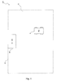
- FIG.1 shows a working apparatus 100 for a limited area S according to one embodiment of the invention.
- the working apparatus 100 comprises a base station 80 and a self-propelling robot 1.
- the self-propelling robot 1 is configured to have a normal operating mode, a base return mode and a stand-by mode.
- the self-propelling robot 1 In the normal operating mode the self-propelling robot 1 is such to perform a working cycle in the area S, indicated in Figure 1 with a broken line.
- the self-propelling robot 1 is for example a lawn-mowing robot, a robot for cleaning swimming pools, a vacuum-cleaner robot or a floor-washing robot. If the self-propelling robot 1 is a lawn-mowing robot, the working area S is a garden delimited by a fence. If the self-propelling robot 1 is a robot for cleaning a swimming pool, the working area S is the swimming pool itself and is thus delimited by the vertical walls of the swimming pool. It should be observed that the working area S is not necessarily delimited by a physical obstacle, but can also be delimited in other ways, such as, for example, by a wire conducting electrical current.
- the self-propelling robot 1 is such to return automatically to the base station 80: this occurs when the battery 70 of the self-propelling robot 1 is low, or when the self-propelling robot 1 has completed a working cycle or when the working hours are over (for example, after 6:00 p.m.).
- the base return mode is activated on expiry of a counter indicating the duration of a working cycle (for example, fifteen minutes) or when the charge level of the battery 70 inside the self-propelling robot 1 is lower than a pre-determined threshold.
- the self-propelling robot 1 In the stand-by mode, the self-propelling robot 1 is stationary inside the base station 80; during this mode the self-propelling robot 1 can be recharged or maintenance can be performed (for example, a filter is drained).
- the base station 80 has the function of housing the self-propelling robot 1 when the latter has ended the working cycle.
- the base station 80 is positioned in a pre-established point, in particular along the perimeter of the working area S; for example, Figure 1 shows that the base station 80 is positioned about halfway along the side S1 of the perimeter of the working area S.
- the base station 80 can be, for example:
- the dimensions of the base station 80 are significantly smaller than the dimensions of the perimeter of the working area S. For example, let's consider a working area S having a rectangular shape with the greatest side S1 and the base station 80 also having a rectangular shape. In this case the dimensions of the greatest side of the base station 80 are significantly smaller than the dimensions of the side S1 of the working area S; for example, the values of the greatest side of the base station 80 are comprised between 15 centimeters and 2 meters, while the values of the side S1 are comprised between 5 meters and 200 meters.
- the base station 80 comprises:
- the processing unit 85 has the function of controlling the value of the magnetic field B.
- the driver circuit 87 has the function of providing suitable signals for controlling the magnetic field generator 86, as a function of the signals generated by the processing unit 85.
- the magnetic field generator 86 has the function of generating a magnetic field B which extends at least in part over the working area S.
- the magnetic field B extends over a part of the working area S: in other words, the intensity of the magnetic field B is not sufficient to be detected by a magnetic field sensor 76 positioned inside the self-propelling robot 1. In this manner, the intensity of the magnetic field B generated by the base station 80 is reduced.
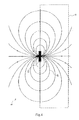
- the magnetic field B has a pattern of lines of force as schematically shown in Fig.4 . It is possible to observe that the lines of force of the magnetic field B extend over at least a part of the working area S. Moreover, all of the lines of force lie in directions which converge towards the base station 80, as shown for example by the line of force 91; in other words, all of the lines of force of the magnetic field B pass through the centre of the base station 80.
- This pattern of the lines of force of the magnetic field B is used by the self-propelling robot 1 to return to the base station 80, as it will be explained in greater detail below.
- the finite number of lines of force shown in Fig.4 are only a schematic representation which has the purpose of showing the direction of the magnetic field B, but in reality infinite lines of force are present; for example, the line of force 91 can be composed of a set of contiguous lines of force.
- the magnetic field generator 86 is implemented with a linear coil 88 of finite length (for example, 10 cm), or with an electrically conducting wire wound around a ferromagnetic core in such a way as to form a plurality of concentric turns, in which an alternating current I flows through the conducting wire.
- the length of the coil 88 (and thus of the ferromagnetic core) is perpendicular to the side S1 (of the perimeter of the working area S) along which the base station 80 is positioned, as shown by the arrow in Fig.4 .
- the length of the coil 88 (and thus of the ferromagnetic core) is parallel to the side S1.
- Figs.2 and 5A-5B show the electrical and electronic components of the self-propelling robot 1.
- the self-propelling robot 1 is configured to return automatically to the base station 80 when the battery 70 of the self-propelling robot 1 is low or when it has completed a working cycle or when the working hours are over (for example, after 6:00 p.m.) or for other functions depending on the application.
- the self-propelling robot 1 comprises:
- the moving means 20 are mounted on the frame 10 and have the function of moving the self-propelling robot 1 in the working area S in the normal operating mode and in the base return mode.
- the moving means 20 comprise, for example, one or more electric motors and four wheels 20a (see Fig.2 ) connected to the electric motors; alternatively, a pair of tracks can be used in place of the wheels 20a, or else a combination of wheels and tracks.
- the electric motors are connected to the wheels 20a (and/or to the pair of tracks) by means of drive assemblies, in such a way as to set the four wheels 20a (and/or pair of tracks) in rotation and thus move the self-propelling robot 1 in the working area S.
- the working means 30 have the function of performing a given type of work in the working area S during the normal operating mode. If the self-propelling robot 1 is a lawn-mowing robot, the working means 30 comprise one or more blades having the function of mowing the grass present in the mowing area S. If the self-propelling robot 1 is a robot for cleaning a swimming pool, the working means 30 comprise inlets for sucking in the debris positioned on the surface S which constitutes the bottom of the pool.
- the gyroscope 45 has the function of measuring the angular velocity of the self-propelling robot 1 around an axis that is vertical with respect to the self-propelling robot 1 (or vertical with respect to the plane defined by the working area S wherein the self-propelling robot 1 moves).
- the gyroscope 45 is such to generate an angular velocity signal S_ ⁇ indicating the angular velocity ⁇ of the self-propelling robot 1 around an axis that is vertical with respect to the self-propelling robot 1 (for example, a vertical axis that passes through the centre of gravity of the self-propelling robot 1).
- the magnetic field sensor 76 has the function of detecting a set of contiguous lines of force of the magnetic field B generated by the base station 80.
- set of contiguous lines of force means the lines of force of the magnetic field B that are such to generate a magnetic flow concatenated with the magnetic field sensor 76.
- the magnetic field sensor 76 is such to detect the variation in the magnetic flow concatenated with the sensor 76 which is caused by a set of contiguous lines of force of the magnetic field B and is such to generate, as a function of said variation in the concatenated magnetic flow, a detection signal S_ril indicating the position of the self-propelling robot 1 with respect to the set of contiguous lines of force of the magnetic field B or indicating the absence of the magnetic field B.
- Position means whether the self-propelling robot 1 is to the right or left of the set of contiguous lines of force of the magnetic field B.
- the self-propelling robot 1 comprises an accelerometer that has the function of measuring the acceleration of the self-propelling robot 1.
- the processing unit 75 of the self-propelling robot 1 is capable of detecting whether the self-propelling robot 1 has reached the base station 80; moreover, the measured acceleration can be used to detect whether the self-propelling robot 1 has struck an obstacle.
- the processing unit 75 has the function of controlling the movement of the self-propelling robot 1 in the working area S, by running algorithms implemented with software code portions. Said algorithms implement the normal operating mode, the base return mode and the stand-by mode.
- the processing unit 75 is for example a microprocessor, in particular Renesas M32C.
- the processing unit 75 is a programmable electronic device (for example, an FPGA) or an application-specific integrated circuit (ASIC).
- the processing unit 75 is such to generate a movement driving signal S_amm in order to control the moving means 20, which perform the movement of the self-propelling robot 1 in the working area S; moreover, the processing unit 75 is such to generate a work driving signal S_aml in order to drive the working means 30, which perform a determined type of work in the working area S.
- the processing unit 75 is such to receive a detection signal S_ril and the angular velocity signal S_ ⁇ as inputs and is such generate, as a function thereof, the movement driving signal S_amm in order to drive the moving means 20 to perform the return of the self-propelling robot 1 to the base station 80, as will be explained in greater detail below.
- the base return mode comprises two phases:
- the self-propelling robot 1 searches for a set of contiguous lines of force of the magnetic field B by following a defined search path 94, as will be explained in greater detail below.
- the self-propelling robot 1 moves tracking the set of contiguous lines of force (previously found in the magnetic field search phase) by means of a plurality of maneuvers of crossing the contiguous lines of force, as will be explained in greater detail below, until reaching the base station 80. Therefore at the end of the base return mode the self-propelling robot 1 has reached the base station 80.
- the processing unit 75 comprises:
- the traveled distance measurement module 75-2 performs an estimation of the distance traveled by the self-propelling robot 1 along the direction of forward travel.
- the distance measurement module is such to generate, as a function of the values of parameters associated with the moving means 20, a traveled distance signal S_d indicating an estimation of the distance traveled by the self-propelling robot 1 along the direction of forward travel.
- the parameters associated with the moving means 20 are, for example, the diameter of the wheels 20a of the self-propelling robot 1 (read by the memory 75-1) and the number of revolutions completed by the wheels 20a.
- the yaw management module 75-3 performs a calculation of the yaw angle, i.e. the angle traveled by the self-propelling robot 1 about an axis that is vertical with respect to the self-propelling robot 1 (for example, a vertical axis that passes through the centre of gravity of the self-propelling robot 1), i.e. vertical with respect to the plane defined by the working area S wherein the self-propelling robot 1 moves.
- this angle is calculated by means of an operation of integrating the values of the angular velocity signal S_ ⁇ .
- the yaw management module 75-3 is configured to generate a yaw signal S_i indicating the present value of the yaw angle of the self-propelling robot 1.
- the memory 75-1 is such to store the values of a length DS of a straight segment and of a side DM, which will be explained in greater detail below.
- the memory 75-1 is such to store a starting yaw value S_i-in indicating the yaw angle at the beginning of the magnetic field tracking phase, i.e. equal to the value of the yaw signal S_i at the beginning of the magnetic field tracking phase.
- the memory 75-1 is configured to store a value of yaw angle minimum difference ⁇ S_i-min equal to the minimum difference of the yaw angle expected in a determined time interval at the end of a maneuver of crossing the set of contiguous lines of force during the magnetic field tracking phase in the base return mode.
- ⁇ S_i-min is equal to 3 degrees in 10 seconds.
- the yaw management module 75-3 performs a calculation of the yaw angle actual difference ⁇ S_i equal to the difference between the value of the final yaw angle and the value of the starting yaw angle, wherein starting yaw angle means the value of the yaw angle at the beginning of the maneuver of crossing the set of contiguous lines of force and wherein final yaw angle means the value of the yaw angle at the end of the crossing maneuver.
- the magnetic field search module 75-4 runs an algorithm (implemented with software code portions) to generate, as a function of the values of the detection signal S_ril and of the traveled distance signal S_d, the movement driving signal S_amm in order to move the self-propelling robot inside the working area S to search for a set of contiguous lines of force of the magnetic field B inside the working area S according to a defined search path 94, as will be described in greater detail below in the description related to the flow chart 200 in Fig.7A .
- the magnetic field tracking module 75-5 runs an algorithm (implemented with software code portions) to generate, as a function of the values of the detection signal S_ril, of the angular velocity signal S_ ⁇ and of the traveled distance signal S_d, the movement driving signal S_amm in order to move the self-propelling robot inside the working area S to track the set of contiguous lines of force previously found by means of a plurality of maneuvers of crossing the set of the contiguous lines of force found until reaching the base station 80, as will be described in greater detail below in the description related to the flow chart 250 of Fig.7B .
- the magnetic field sensor 76 is implemented with two coils 76-1, 76-2, each composed of an electrically conducting wire wound around a ferromagnetic material in such a way as to form a plurality of concentric turns, wherein the mutual orientation of the coils 76-1, 76-2 is equal to 90 degrees (i.e. the two coils 76-1, 76-2 are physically positioned at 90 degrees from each other) and the position of the coils is horizontal with respect to the plane defined by the working area S.
- the magnetic field B has a flow concatenated with the surface of the two coils 76-1, 76-2, wherein the surface is the cross section of each coil 76-1, 76-2.
- the movement of the self-propelling robot 1 in the magnetic field B causes a variation in the flow concatenated with the coils 76-1, 76-2, which produces (by mutual induction) respective electromotive forces induced at the ends of the two coils 76-1, 76-2, wherein the induced electromotive forces have an amplitude and a phase which depends on the position of the two coils 76-1, 76-2 with respect to the set of contiguous lines of force of the magnetic field B.
- By measuring the phase and amplitude difference between the electromotive forces induced at the ends of the two coils 76-1, 76-2 it is possible to discriminate the position of the self-propelling robot 1 with respect to the set of contiguous lines of force of the magnetic field B (i.e. whether it is in a right or left position).
- the detection signal S_ril is the phase and amplitude difference between the electromotive forces induced at the ends of the two coils 76-1, 76-2.
- FIG.6A shows a search path 94 followed by the self-propelling robot 1 in the magnetic field search phase of the base return mode, wherein the self-propelling robot 1 searches for a set 91 of contiguous lines of force of the magnetic field B.
- the self-propelling robot 1 is configured to follow at least a part of the search path 94 that is located inside an area of maneuver AM, which is a square having sides with a length 2*DM.
- the side DM has a much lower value than that of the side S1 of the perimeter of the working area S; for example, the side DM has a value equal to 1 metre.
- the search path 94 comprises:
- Fig.6B shows the tracking path 92 followed by the self-propelling robot 1 to track a set of contiguous lines of force 91-1 in the magnetic field tracking phase of the base return mode and thus reach the base station 80.
- the set of contiguous lines of force 91-1 is a portion of the line of force 91 shown in Fig.4 .
- the self-propelling robot 1 remains locked to the set of contiguous lines of force and tracks it in the direction which converges towards the base station 80, until reaching it. Since the self-propelling robot 1 moves by tracking a set of contiguous lines of force in the direction converging towards the base station 80, this implies that it move towards a higher intensity of the magnetic field B.
- the self-propelling robot 1 is configured to follow a zig-zag tracking path 92 around a set of contiguous lines of force 91-1 of the magnetic field B, by means of a plurality of maneuvers of crossing the set of contiguous lines of force 91-1.
- the tracking path 92 comprises:
- the portions 92-2 and 92-3 together constitute the maneuver of crossing the set of contiguous lines of force 91-1.
- the portions 92-5 and 92-6 together constitute another maneuver of crossing the set of contiguous lines of force 91-1.
- the value of the length DS is determined experimentally and is for example equal to 4 cm.
- the tracking path 92 followed by the self-propelling robot 1 is particularly advantageous because it allows the self-propelling robot 1 to return to the base station 80 in reduced times and in a reliable manner from any point of the working area S wherein the magnetic field B is present, without following a preferential direction.
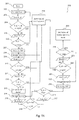
- Fig.7A shows the flow chart 200 of the magnetic field search phase of the base return mode and the Fig.7B shows the flow chart 250 of the magnetic field tracking phase of the base return mode.
- the steps 201-226 of the flow chart 200 and the steps 227-253 of the flow chart 250 are performed by the processing unit 75, by means of respective algorithms implemented with software code portions.
- the programming language used is for example the C language.
- the flow chart 200 receives as inputs the value of the side DM, the detection signal S_ril generated by the magnetic field sensor 76 and the traveled distance signal S_d calculated by the processing unit 75 and generates as output the movement driving signal S_amm to drive the moving means 20 and thus to move the self-propelling robot 1 to follow the search path 94 shown in Fig.6A .
- the flow chart 250 receives the following signals as inputs:
- the movement driving signal S_amm is generated as output, as a function of the values of the above described input signals, in order to drive the moving means 20 and thus to move the self-propelling robot 1 so as to track the set of the contiguous lines of force previously found (by means of the flow chart 200) according to the tracking path 92 shown in Fig.6B , until reaching the base station 80.
- the magnetic field search phase is activated for example when the charge level of the battery 70 inside the self-propelling robot 1 is lower a pre-determined threshold, or on expiry of a counter indicating the duration of a working cycle (for example, fifteen minutes) or when the working hours are over (for example, after 6:00 p.m.).
- the magnetic field search phase of the base return mode begins with the step 201.
- step 202 the self-propelling robot 1 moves straight forward, i.e. along a substantially straight trajectory, as shown in the portion of the search path 94 of Fig. 6A comprised between P0 and P1 (excluding P1).
- step 203 it is read the value of the detection signal S_ril.
- step 204 it is verified whether the value of the detection signal S_ril indicates that the self-propelling robot 1 is to the left or to the right of a set of contiguous lines of force:
- step 205 it is read the value of the traveled distance signal S_d indicating the distance traveled by the self-propelling robot 1.
- step 206 it is verified whether the value of the traveled distance signal S_d is greater than or equal to 2*DM:
- the loop composed of the steps 202, 203, 204, 205, 206 is performed until the self-propelling robot 1 finds a set of contiguous lines of force of the magnetic field B or until the self-propelling robot 1 has traveled a distance equal to 2*DM (i.e. the portion of the search path 94 of Fig.6A comprised between the points P0 and P1).
- step 207 the self-propelling robot 1 rotates around itself by 180 degrees, as shown in the point P1 of Fig.6A .
- step 208 the self-propelling robot 1 moves straight forward, as shown in the portion of the search path 94 of Fig.6A comprised between P1 and P2.
- step 209 it is read the value of the detection signal S_ril.
- step 210 it is verified whether the value of the detection signal S_ril indicates that the self-propelling robot 1 is to the left or to the right of a set of contiguous lines of force:
- step 211 it is read the value of the traveled distance signal S_d indicating the distance traveled by the self-propelling robot 1.
- step 212 it is verified whether the value of the traveled distance signal S_d is greater than or equal to DM:
- the loop composed of the steps 208, 209, 210, 211, 212 is performed until the self-propelling robot 1 finds a set of contiguous lines of force of the magnetic field B or until the self-propelling robot 1 has traveled a distance equal to DM (i.e. the portion of the search path 94 of Fig.6A comprised between the points P1 and P2).
- step 213 the self-propelling robot 1 rotates by 90 degrees to the left, as shown in the point P2 of Fig.6A .
- step 214 the self-propelling robot 1 moves straight forward, as shown in the portion of the search path 94 of Fig.6A comprised between P2 and P3.
- step 215 it is read the value of the detection signal S_ril.
- step 216 it is verified whether the value of the detection signal S_ril indicates that the self-propelling robot 1 is to the left or to the right of a set of contiguous lines of force:
- step 217 it is read the value of the traveled distance signal S_d indicating the distance traveled by the self-propelling robot 1.
- step 218 it is verified whether the value of the traveled distance signal S_d is greater than or equal to DM:
- the loop composed of the steps 214, 215, 216, 217, 218 is performed until the self-propelling robot 1 finds a set of contiguous lines of force of the magnetic field B or until the self-propelling robot 1 has traveled a distance equal to DM (i.e. the portion of the search path 94 of Fig.6A comprised between the points P2 and P3).
- step 219 the self-propelling robot 1 rotates by 180 degrees around itself, as shown in the point P3 of Fig.6A .
- step 220 the self-propelling robot 1 moves straight forward, as shown in the portion of the search path 94 of Fig.6A comprised between P3 and P4.
- step 221 it is read the value of the detection signal S_ril.
- step 222 it is verified whether the value of the detection signal S_ril indicates that the self-propelling robot 1 is to the left or to the right of a set of contiguous lines of force:
- step 223 it is read the value of the traveled distance signal S_d indicating the distance traveled by the self-propelling robot 1.
- step 224 it is verified whether the value of the traveled distance signal S_d is greater than or equal to 2*DM:
- step 225 the normal operating mode is activated.
- the self-propelling robot 1 if the self-propelling robot 1 has completed the search path 94 and has not found the set of contiguous lines of force of the magnetic field B, the self-propelling robot 1 quits the base return mode and goes back to the normal operating mode, wherein it performs the movements analogously to when it performs a working cycle in the working area S.
- the self-propelling robot 1 will again make a transition from the normal operating mode to the magnetic field search phase of the base return mode, following again the search path 94, but starting from a different starting position inside the working area S: in this manner the self-propelling robot 1 will follow a different trajectory (compared to the one of the previous magnetic field search phase) inside the working area S and thus there will be an increased probability of the self-propelling robot 1 being located (along the search path 94) in a position of the working area S wherein the magnetic field B is present, as a result of subsequent activations of the magnetic field search phase.
- the side DM of the search path 94 has a greater value which is proportional to the side S1 of the perimeter of the working area S (for example, the value of the side DM is half the value of the side S1).
- the side DM has a value equal to 50 metres.
- the magnetic field tracking phase of the base return mode begins with step 227.
- step 228 it is read the value of the detection signal S_ril.
- step 229 it is verified whether the value of the detection signal S_ril indicates that the self-propelling robot 1 is to the left of a set of contiguous lines of force:
- step 230 the self-propelling robot 1 moves straight forward, as shown in the portion 92-1 of the tracking path 92 of Fig.6B .
- step 231 it is verified whether the self-propelling robot 1 has reached the base station 80:
- step 232 it is read the value of the traveled distance signal S_d indicating the distance traveled by the self-propelling robot 1.
- step 233 it is verified whether the value of the traveled distance signal S_d is greater than or equal to the value of the length DS:
- step 234 the self-propelling robot 1 turns to the right, thus beginning to travel along the portion 92-2 of the tracking path 92.
- step 235 it is verified whether the value of the yaw angle actual difference ⁇ S_i is greater than the value of the yaw angle minimum difference ⁇ S_i-min:
- step 236 it is read the value of the detection signal S_ril.
- step 237 it is verified whether the value of the detection signal S_ril indicates that the magnetic field B is not present:
- step 238 it is verified whether the value of the detection signal S_ril indicates that the self-propelling robot 1 is to the right of a set of contiguous lines of force:
- the loop composed of the steps 234, 235, 236, 237, 238 is performed until the self-propelling robot 1 has traveled the entire portion 92-3 of the tracking path 92 and is located to the right of the set of contiguous lines of force.
- step 240 the operation is analogous to that described previously starting from step 230, with the difference that the self-propelling robot 1 is located to the right of the set of contiguous lines of force.
- the self-propelling robot 1 is located to the right of the set of contiguous lines of force.
- step 249 in case wherein it is detected that the magnetic field B is not present. This occurs in the event that the self-propelling robot 1 has moved in a direction opposite to the one wherein the base station 80 is located.
- step 249 the self-propelling robot 1 performs a 180 degree rotation around itself: in this way the self-propelling robot 1 will again be positioned in the direction towards the base station 80 and there will again be an activation of the magnetic field search phase of the base return mode (step 200-1) wherein the flow chart 200 is again executed.
- step 239 in case wherein the value of the yaw angle actual difference ⁇ S_i is smaller than the value of the minimum yaw angle difference ⁇ S_i-min. This occurs in the event that the self-propelling robot 1 has reached an obstacle or in the event that the self-propelling robot 1 is in proximity to the base station 80, in particular in the event that it has reached a lateral wall of the base station 80: under these conditions, in fact, the value of the yaw angle (signal S_i) does not increase notwithstanding that the self-propelling robot 1 has performed a rotation to the right in step 234 (or to the left in step 244).
- step 239 it is verified whether the present value of the yaw angle (signal S_i) is greater than the starting yaw value S_i-in:
- step 250 the self-propelling robot 1 performs a 90 degree back-rotation to the right (in other words, the self-propelling robot 1 travels rightward over an arc of a circle that forms a 90 degree angle), whereas in step 252 the self-propelling robot 1 performs a 90 degree back-rotation to the left (in other words, the self-propelling robot 1 travels leftward over an arc of a circle that forms a 90 degree angle): in this manner the self-propelling robot 1 will be positioned facing the base station 80 and there will again be an activation of the magnetic field search phase of the base return mode (step 200-1) wherein the flow chart 200 is again executed.
- the battery 70 is recharged by means of an inductive coupling between the generator 86 of the magnetic field B inside the base station 80 and the sensor 76 of the magnetic field B inside the self-propelling robot 1, as described in greater detail in European patent application no. 12160183.5 filed on 19 March 2012 in the name of the same Applicant.
- the self-propelling robot 1 is a lawn-mowing robot, that the working means 30 are blades and that the working area S is a lawn wherein it is necessary to mow the grass.
- the lawn-mowing robot 1 At the starting time t0 the lawn-mowing robot 1 is in the normal operating mode, wherein it performs a grass mowing cycle in the lawn S.
- the lawn-mowing robot 1 mows the grass in at least a part of the lawn S.
- the processing unit 75 inside the lawn-mowing robot 1 detects that the battery 70 is discharging and activates the base return mode; in particular, the processing unit 75 activates the magnetic field search phase of the base return mode.
- the lawn-mowing robot 1 follows the search path 94 shown in Fig.6A up to point P3 and then carries out steps 201-215 of the method 200 of Fig.7A , as previously described.
- the sensor 76 At time t2 (subsequent to t1) the sensor 76 generates the detection signal S_ril which indicates that the lawn-mowing robot 1 is located to the left of a set of contiguous lines of force and thus the processing unit 75 activates the tracking phase (steps 216 and 226 of the method 200 of Fig.7A ).
- the lawn-mowing robot begins following the zig-zag tracking path 92 around the set of lines of force found at time t2, carrying out steps 228, 229 of the method 250 of Fig.7B .
- the lawn-mowing robot 1 follows the zig-zag tracking path 92 around the set of lines of force found at time t2, carrying out the steps of the method 250 of Fig.7B (except for step 200-1), as previously described.
- the lawn-mowing robot 1 detects that it has reached the base station 80 and activates the stand-by mode.
- the lawn-mowing robot 1 follows the whole search path 94 shown in Fig.6A up to point P4 without detecting the presence of the magnetic field B and thus carries out the steps of the method 200 of Fig.7A until arriving at step 224.
- the processing unit 75 activates for a first time the normal operating mode (step 225) and the lawn-mowing robot 1 resumes the working cycle.
- the processing unit 75 activates for a second time the magnetic field search phase.
- the lawn-mowing robot 1 follows a part of the search path 94 shown in Fig.6A .
- the sensor 76 At time t2 (subsequent to t1"') the sensor 76 generates the detection signal S_ril indicating that the lawn-mowing robot 1 is located to the left of a set of contiguous lines of force and thus the processing unit 75 activates the tracking phase (step 226 of the method 200 of Fig.7A ) and thus the operation continues analogously to what was previously described at time t2.
- the lawn-mowing robot 1 follows for a first time the whole search path 94 in the search phase, executes for a first time the normal operating mode, follows for a second time the whole search path 94 in the search phase, executes for a second time the normal operating mode, follows for a third time a part of the search path 94 and finally carries out the tracking phase.
- the method comprises the step a) of generating a magnetic field extending at least in part over a limited working area, the step b) of activating a base return mode, the step c) of moving the self-propelling robot inside the working area to search for a set of contiguous lines of force of the magnetic field inside the working area according to a defined search path, and the step d) of moving the self-propelling robot inside the working area to track at least a portion of the set of found contiguous lines of force by means of a plurality of maneuvers of crossing the set of the found contiguous lines of force until reaching the base station.
- It is also an object of the present invention a computer program comprising software code portions adapted to carry out the steps b), c), d) of the method for controlling the return to the base station of the self-propelling robot, when said program is run on an a computer.
Landscapes
- Engineering & Computer Science (AREA)
- Physics & Mathematics (AREA)
- Remote Sensing (AREA)
- Radar, Positioning & Navigation (AREA)
- Aviation & Aerospace Engineering (AREA)
- Automation & Control Theory (AREA)
- General Physics & Mathematics (AREA)
- Power Engineering (AREA)
- Architecture (AREA)
- Transportation (AREA)
- Mechanical Engineering (AREA)
- Electromagnetism (AREA)
- Life Sciences & Earth Sciences (AREA)
- Structural Engineering (AREA)
- Civil Engineering (AREA)
- Sustainable Development (AREA)
- Sustainable Energy (AREA)
- Environmental Sciences (AREA)
- Control Of Position, Course, Altitude, Or Attitude Of Moving Bodies (AREA)
- Manipulator (AREA)
- Control And Other Processes For Unpacking Of Materials (AREA)
- User Interface Of Digital Computer (AREA)
- Processing Of Meat And Fish (AREA)
Abstract
Description
- The present invention generally relates to the field of self-propelling robots. More in particular, the present invention relates to a working apparatus for a limited area.
- There are known self-propelling robots, such as for example lawn-mowing robots, pool cleaning robots, vacuum-cleaner robots or floor-washing robots. These robots are capable of moving autonomously by virtue of a rechargeable battery, which has the purpose of supplying power to the electrical and electromechanical devices present inside the robot, such as, for example, motors for moving wheels and blades, sensors and data processing units.
- When the battery charge level is too low, the robot moves automatically until reaching a base recharging station, wherein the battery can be recharged.
- Similarly, when the robot has completed the working cycle (for example, lawn mowing, pool cleaning, vacuum cleaning or floor washing), the robot moves automatically until reaching the base station, such as, for example, a point for draining the filter.
- International patent application
WO 03/104909 inner conductor loop 3 and a largerouter loop 2 connected to an alternating current generator 1 (seeFig.1 ), wherein the surface defined by theouter loop 2 corresponds to the working area of the self-propelling device. In this manner, theinner loop 3 and theouter loop 2 generate respective magnetic fields. The lawn-mowing robot includes a receiver 14 for the magnetic fields (for example, one or more conductive turns wound around a magnetic core) and uses the magnetic field received from theouter loop 2 and theinner loop 3 to return to arecharging station 3. - The Applicant has observed that said electronic navigational control system for lawn-mowing robots has the following disadvantages:
- it is too complex, because it requires the use of two current conductor loops;
- the time it takes the lawn-mowing robot to return to the recharging
station 3 is too long; - the lawn-mowing robot can reach the base only by following a preferential direction, in particular by following the direction in which the magnetic field is zero (see line 55 in Fig.12);
- it is too expensive.
- European patent application having publication number
1906205 discloses a system for determining if a self-propelling robot is in an external or internal position with respect to a wire having a loop shape which defines the working area. - Japanese patent application having publication number
2002-352374 - International patent application having publication number 2011/129728 discloses a system for guiding a lawn-mower robot towards a charging station using two signals received from two respective sources of magnetic field signal or of electrical current signal.
- The present invention relates to a working apparatus for a limited area as defined in the enclosed
claim 1 and by its preferred embodiments thereof described independent claims 2 to 10. - The Applicant has perceived that the working apparatus according to the present invention has the following advantages:
- it reduces the time it takes for the self-propelling robot to return to the base station or to a pre-established point and, consequently, it reduces the energy consumed to return to the base station;
- it increases the reliability of the process of returning to the base station;
- it is simple to implement;
- it is less expensive.
- Further features and advantages of the invention will become apparent from the description that follows of a preferred embodiment and the variants thereof provided by way of example with reference to the appended drawings, in which:
-
Fig.1 schematically shows a working apparatus for a limited area according to one embodiment of the invention; -
Fig.2 schematically shows a perspective view of a self-propelling robot included into the working apparatus according to the embodiment of the invention; -
Fig.3 shows a block diagram of the base station included into the working apparatus according to the embodiment of the invention; -
Fig.4 schematically shows a possible pattern of the magnetic field generated by the base station; -
Fig.5A shows a block diagram of the self-propelling robot; -
Fig.5B shows more in detail the processing unit of the block diagram ofFig.5A ; -
Figs.6A-6B show the search path and the tracking path followed by the self-propelling robot during a base return mode respectively; -
Figs.7A-7B show the flow charts of a magnetic field search phase and of a magnetic field tracking phase respectively of the base return mode performed by the processing unit of the self-propelling robot. - With reference to
Fig.1 , it shows a workingapparatus 100 for a limited area S according to one embodiment of the invention. - The working
apparatus 100 comprises abase station 80 and a self-propelling robot 1. - The self-
propelling robot 1 is configured to have a normal operating mode, a base return mode and a stand-by mode. - In the normal operating mode the self-
propelling robot 1 is such to perform a working cycle in the area S, indicated inFigure 1 with a broken line. The self-propellingrobot 1 is for example a lawn-mowing robot, a robot for cleaning swimming pools, a vacuum-cleaner robot or a floor-washing robot. If the self-propellingrobot 1 is a lawn-mowing robot, the working area S is a garden delimited by a fence. If the self-propellingrobot 1 is a robot for cleaning a swimming pool, the working area S is the swimming pool itself and is thus delimited by the vertical walls of the swimming pool. It should be observed that the working area S is not necessarily delimited by a physical obstacle, but can also be delimited in other ways, such as, for example, by a wire conducting electrical current. - In the base return mode the self-
propelling robot 1 is such to return automatically to the base station 80: this occurs when thebattery 70 of the self-propelling robot 1 is low, or when the self-propelling robot 1 has completed a working cycle or when the working hours are over (for example, after 6:00 p.m.). For example, the base return mode is activated on expiry of a counter indicating the duration of a working cycle (for example, fifteen minutes) or when the charge level of thebattery 70 inside the self-propelling robot 1 is lower than a pre-determined threshold. - In the stand-by mode, the self-
propelling robot 1 is stationary inside thebase station 80; during this mode the self-propelling robot 1 can be recharged or maintenance can be performed (for example, a filter is drained). - The
base station 80 has the function of housing the self-propellingrobot 1 when the latter has ended the working cycle. Thebase station 80 is positioned in a pre-established point, in particular along the perimeter of the working area S; for example,Figure 1 shows that thebase station 80 is positioned about halfway along the side S1 of the perimeter of the working area S. Thebase station 80 can be, for example: - a recharging station, having the function of recharging the
battery 70 of the self-propelling robot 1; - a point for draining a filter.
- The dimensions of the
base station 80 are significantly smaller than the dimensions of the perimeter of the working area S. For example, let's consider a working area S having a rectangular shape with the greatest side S1 and thebase station 80 also having a rectangular shape. In this case the dimensions of the greatest side of thebase station 80 are significantly smaller than the dimensions of the side S1 of the working area S; for example, the values of the greatest side of thebase station 80 are comprised between 15 centimeters and 2 meters, while the values of the side S1 are comprised between 5 meters and 200 meters. - With reference to
Fig.3 , it shows the electronic components inside thebase station 80. Thebase station 80 comprises: - a
processing unit 85; - a
driver circuit 87; - a
generator 86 of a magnetic field B. - The
processing unit 85 has the function of controlling the value of the magnetic field B. - The
driver circuit 87 has the function of providing suitable signals for controlling themagnetic field generator 86, as a function of the signals generated by theprocessing unit 85. - The
magnetic field generator 86 has the function of generating a magnetic field B which extends at least in part over the working area S. Advantageously, the magnetic field B extends over a part of the working area S: in other words, the intensity of the magnetic field B is not sufficient to be detected by amagnetic field sensor 76 positioned inside the self-propelling robot 1. In this manner, the intensity of the magnetic field B generated by thebase station 80 is reduced. - The magnetic field B has a pattern of lines of force as schematically shown in
Fig.4 . It is possible to observe that the lines of force of the magnetic field B extend over at least a part of the working area S. Moreover, all of the lines of force lie in directions which converge towards thebase station 80, as shown for example by the line offorce 91; in other words, all of the lines of force of the magnetic field B pass through the centre of thebase station 80. This pattern of the lines of force of the magnetic field B is used by the self-propellingrobot 1 to return to thebase station 80, as it will be explained in greater detail below. It is observed that the finite number of lines of force shown inFig.4 are only a schematic representation which has the purpose of showing the direction of the magnetic field B, but in reality infinite lines of force are present; for example, the line offorce 91 can be composed of a set of contiguous lines of force. - Preferably, the
magnetic field generator 86 is implemented with alinear coil 88 of finite length (for example, 10 cm), or with an electrically conducting wire wound around a ferromagnetic core in such a way as to form a plurality of concentric turns, in which an alternating current I flows through the conducting wire. The length of the coil 88 (and thus of the ferromagnetic core) is perpendicular to the side S1 (of the perimeter of the working area S) along which thebase station 80 is positioned, as shown by the arrow inFig.4 . - Alternatively, the length of the coil 88 (and thus of the ferromagnetic core) is parallel to the side S1.
- With reference to
Figs.2 and5A-5B , they show the electrical and electronic components of the self-propellingrobot 1. The self-propellingrobot 1 is configured to return automatically to thebase station 80 when thebattery 70 of the self-propellingrobot 1 is low or when it has completed a working cycle or when the working hours are over (for example, after 6:00 p.m.) or for other functions depending on the application. - The self-propelling
robot 1 comprises: - a
frame 10; - moving means 20;
- working means 30;
- a
processing unit 75; - a
battery 70; - a
gyroscope 45; - a
magnetic field sensor 76. - The moving means 20 are mounted on the
frame 10 and have the function of moving the self-propellingrobot 1 in the working area S in the normal operating mode and in the base return mode. The moving means 20 comprise, for example, one or more electric motors and fourwheels 20a (seeFig.2 ) connected to the electric motors; alternatively, a pair of tracks can be used in place of thewheels 20a, or else a combination of wheels and tracks. The electric motors are connected to thewheels 20a (and/or to the pair of tracks) by means of drive assemblies, in such a way as to set the fourwheels 20a (and/or pair of tracks) in rotation and thus move the self-propellingrobot 1 in the working area S. - The working means 30 have the function of performing a given type of work in the working area S during the normal operating mode. If the self-propelling
robot 1 is a lawn-mowing robot, the working means 30 comprise one or more blades having the function of mowing the grass present in the mowing area S. If the self-propellingrobot 1 is a robot for cleaning a swimming pool, the working means 30 comprise inlets for sucking in the debris positioned on the surface S which constitutes the bottom of the pool. - The
gyroscope 45 has the function of measuring the angular velocity of the self-propellingrobot 1 around an axis that is vertical with respect to the self-propelling robot 1 (or vertical with respect to the plane defined by the working area S wherein the self-propellingrobot 1 moves). In particular, thegyroscope 45 is such to generate an angular velocity signal S_ω indicating the angular velocity ω of the self-propellingrobot 1 around an axis that is vertical with respect to the self-propelling robot 1 (for example, a vertical axis that passes through the centre of gravity of the self-propelling robot 1). - The
magnetic field sensor 76 has the function of detecting a set of contiguous lines of force of the magnetic field B generated by thebase station 80. The term "set of contiguous lines of force" means the lines of force of the magnetic field B that are such to generate a magnetic flow concatenated with themagnetic field sensor 76. More in particular, themagnetic field sensor 76 is such to detect the variation in the magnetic flow concatenated with thesensor 76 which is caused by a set of contiguous lines of force of the magnetic field B and is such to generate, as a function of said variation in the concatenated magnetic flow, a detection signal S_ril indicating the position of the self-propellingrobot 1 with respect to the set of contiguous lines of force of the magnetic field B or indicating the absence of the magnetic field B. Position means whether the self-propellingrobot 1 is to the right or left of the set of contiguous lines of force of the magnetic field B. - Preferably, the self-propelling
robot 1 comprises an accelerometer that has the function of measuring the acceleration of the self-propellingrobot 1. In this manner, theprocessing unit 75 of the self-propellingrobot 1 is capable of detecting whether the self-propellingrobot 1 has reached thebase station 80; moreover, the measured acceleration can be used to detect whether the self-propellingrobot 1 has struck an obstacle. - The
processing unit 75 has the function of controlling the movement of the self-propellingrobot 1 in the working area S, by running algorithms implemented with software code portions. Said algorithms implement the normal operating mode, the base return mode and the stand-by mode. - The
processing unit 75 is for example a microprocessor, in particular Renesas M32C. Alternatively, theprocessing unit 75 is a programmable electronic device (for example, an FPGA) or an application-specific integrated circuit (ASIC). - More in particular, in the normal operating mode the
processing unit 75 is such to generate a movement driving signal S_amm in order to control the movingmeans 20, which perform the movement of the self-propellingrobot 1 in the working area S; moreover, theprocessing unit 75 is such to generate a work driving signal S_aml in order to drive the working means 30, which perform a determined type of work in the working area S. - In the base return mode, the
processing unit 75 is such to receive a detection signal S_ril and the angular velocity signal S_ω as inputs and is such generate, as a function thereof, the movement driving signal S_amm in order to drive the moving means 20 to perform the return of the self-propellingrobot 1 to thebase station 80, as will be explained in greater detail below. - The base return mode comprises two phases:
- a magnetic field search phase;
- a subsequent magnetic field tracking phase.
- In the magnetic field search phase, the self-propelling
robot 1 searches for a set of contiguous lines of force of the magnetic field B by following a definedsearch path 94, as will be explained in greater detail below. - In the magnetic field tracking phase, the self-propelling
robot 1 moves tracking the set of contiguous lines of force (previously found in the magnetic field search phase) by means of a plurality of maneuvers of crossing the contiguous lines of force, as will be explained in greater detail below, until reaching thebase station 80. Therefore at the end of the base return mode the self-propellingrobot 1 has reached thebase station 80. - With reference to
Fig.5B , theprocessing unit 75 comprises: - a memory 75-1;
- a traveled distance measurement module 75-2;
- a yaw management module 75-3;
- a magnetic field search module 75-4;
- a magnetic field tracking module 75-5.
- The traveled distance measurement module 75-2 performs an estimation of the distance traveled by the self-propelling
robot 1 along the direction of forward travel. In particular, the distance measurement module is such to generate, as a function of the values of parameters associated with the movingmeans 20, a traveled distance signal S_d indicating an estimation of the distance traveled by the self-propellingrobot 1 along the direction of forward travel. The parameters associated with the moving means 20 are, for example, the diameter of thewheels 20a of the self-propelling robot 1 (read by the memory 75-1) and the number of revolutions completed by thewheels 20a. - The yaw management module 75-3 performs a calculation of the yaw angle, i.e. the angle traveled by the self-propelling
robot 1 about an axis that is vertical with respect to the self-propelling robot 1 (for example, a vertical axis that passes through the centre of gravity of the self-propelling robot 1), i.e. vertical with respect to the plane defined by the working area S wherein the self-propellingrobot 1 moves. Preferably, this angle is calculated by means of an operation of integrating the values of the angular velocity signal S_ω. In particular, the yaw management module 75-3 is configured to generate a yaw signal S_i indicating the present value of the yaw angle of the self-propellingrobot 1. - The memory 75-1 is such to store the values of a length DS of a straight segment and of a side DM, which will be explained in greater detail below.
- Moreover, the memory 75-1 is such to store a starting yaw value S_i-in indicating the yaw angle at the beginning of the magnetic field tracking phase, i.e. equal to the value of the yaw signal S_i at the beginning of the magnetic field tracking phase. Moreover, the memory 75-1 is configured to store a value of yaw angle minimum difference ΔS_i-min equal to the minimum difference of the yaw angle expected in a determined time interval at the end of a maneuver of crossing the set of contiguous lines of force during the magnetic field tracking phase in the base return mode. For example, ΔS_i-min is equal to 3 degrees in 10 seconds.
- Moreover, the yaw management module 75-3 performs a calculation of the yaw angle actual difference ΔS_i equal to the difference between the value of the final yaw angle and the value of the starting yaw angle, wherein starting yaw angle means the value of the yaw angle at the beginning of the maneuver of crossing the set of contiguous lines of force and wherein final yaw angle means the value of the yaw angle at the end of the crossing maneuver.
- The magnetic field search module 75-4 runs an algorithm (implemented with software code portions) to generate, as a function of the values of the detection signal S_ril and of the traveled distance signal S_d, the movement driving signal S_amm in order to move the self-propelling robot inside the working area S to search for a set of contiguous lines of force of the magnetic field B inside the working area S according to a defined
search path 94, as will be described in greater detail below in the description related to theflow chart 200 inFig.7A . - The magnetic field tracking module 75-5 runs an algorithm (implemented with software code portions) to generate, as a function of the values of the detection signal S_ril, of the angular velocity signal S_ω and of the traveled distance signal S_d, the movement driving signal S_amm in order to move the self-propelling robot inside the working area S to track the set of contiguous lines of force previously found by means of a plurality of maneuvers of crossing the set of the contiguous lines of force found until reaching the
base station 80, as will be described in greater detail below in the description related to theflow chart 250 ofFig.7B . - Advantageously, the
magnetic field sensor 76 is implemented with two coils 76-1, 76-2, each composed of an electrically conducting wire wound around a ferromagnetic material in such a way as to form a plurality of concentric turns, wherein the mutual orientation of the coils 76-1, 76-2 is equal to 90 degrees (i.e. the two coils 76-1, 76-2 are physically positioned at 90 degrees from each other) and the position of the coils is horizontal with respect to the plane defined by the working area S. When the self-propellingrobot 1 is in the magnetic field B generated by thebase station 80, the magnetic field B has a flow concatenated with the surface of the two coils 76-1, 76-2, wherein the surface is the cross section of each coil 76-1, 76-2. The movement of the self-propellingrobot 1 in the magnetic field B causes a variation in the flow concatenated with the coils 76-1, 76-2, which produces (by mutual induction) respective electromotive forces induced at the ends of the two coils 76-1, 76-2, wherein the induced electromotive forces have an amplitude and a phase which depends on the position of the two coils 76-1, 76-2 with respect to the set of contiguous lines of force of the magnetic field B. By measuring the phase and amplitude difference between the electromotive forces induced at the ends of the two coils 76-1, 76-2, it is possible to discriminate the position of the self-propellingrobot 1 with respect to the set of contiguous lines of force of the magnetic field B (i.e. whether it is in a right or left position). - Therefore, if the
magnetic field sensor 76 is implemented with two coils 76-1, 76-2, the detection signal S_ril is the phase and amplitude difference between the electromotive forces induced at the ends of the two coils 76-1, 76-2. - With reference to
Fig.6A , it shows asearch path 94 followed by the self-propellingrobot 1 in the magnetic field search phase of the base return mode, wherein the self-propellingrobot 1 searches for aset 91 of contiguous lines of force of the magnetic field B. - It is possible to observe that the self-propelling
robot 1 is configured to follow at least a part of thesearch path 94 that is located inside an area of maneuver AM, which is a square having sides with alength 2*DM. The side DM has a much lower value than that of the side S1 of the perimeter of the working area S; for example, the side DM has a value equal to 1 metre. - In particular, the
search path 94 comprises: - a portion comprised between the points P0 and P1 (excluding P1) which is substantially straight with a
length 2*DM; - a point P1 wherein the self-propelling
robot 1 performs a 180 degree rotation; - a portion comprised between the points P1 and P2 (excluding P2) which is substantially straight with a length DM;
- a point P2 wherein the self-propelling
robot 1 performs a 90 rotation degree to the left; - a portion comprised between the points P2 and P3 (excluding P3) which is substantially straight with a length DM;
- a point P3 wherein the self-propelling
robot 1 performs a 180 degree rotation so as to reverse the direction of travel; - a portion comprised between the points P3 and P4 which is substantially straight with a
length 2*DM. - It is observed that the combination of the
search path 94 together with the activation of the normal operating mode (step 225 inFig.7A ) allows to guide the self-propellingrobot 1 towards the area surrounding thebase station 80 wherein the magnetic field B is present, as will be explained in greater detail below with reference to description ofFig.7A . - With reference to
Fig.6B , it shows the trackingpath 92 followed by the self-propellingrobot 1 to track a set of contiguous lines of force 91-1 in the magnetic field tracking phase of the base return mode and thus reach thebase station 80. It is observed that the set of contiguous lines of force 91-1 is a portion of the line offorce 91 shown inFig.4 . In fact, after finding the set of contiguous lines of force 91-1, the self-propellingrobot 1 remains locked to the set of contiguous lines of force and tracks it in the direction which converges towards thebase station 80, until reaching it. Since the self-propellingrobot 1 moves by tracking a set of contiguous lines of force in the direction converging towards thebase station 80, this implies that it move towards a higher intensity of the magnetic field B. - It is possible to observe that the self-propelling
robot 1 is configured to follow a zig-zag tracking path 92 around a set of contiguous lines of force 91-1 of the magnetic field B, by means of a plurality of maneuvers of crossing the set of contiguous lines of force 91-1. In particular, the trackingpath 92 comprises: - portions 92-1, 92-4 of a length DS wherein the self-propelling
robot 1 moves in a direction which is substantially parallel to the set of contiguous lines of force 91-1 of the magnetic field B; - portions 92-2, 92-5 wherein the self-propelling
robot 1 performs a rotation towards the set of contiguous lines of force 91-1; - portions 92-3, 92-6 wherein the self-propelling
robot 1 moves in a direction substantially perpendicular to the set of contiguous lines of force 91-1, in such a way as to cross the set of contiguous lines of force 91-1. - The portions 92-2 and 92-3 together constitute the maneuver of crossing the set of contiguous lines of force 91-1. Analogously, the portions 92-5 and 92-6 together constitute another maneuver of crossing the set of contiguous lines of force 91-1.
- The value of the length DS is determined experimentally and is for example equal to 4 cm.
- It is observed that the tracking
path 92 followed by the self-propellingrobot 1 is particularly advantageous because it allows the self-propellingrobot 1 to return to thebase station 80 in reduced times and in a reliable manner from any point of the working area S wherein the magnetic field B is present, without following a preferential direction. -
Fig.7A shows theflow chart 200 of the magnetic field search phase of the base return mode and theFig.7B shows theflow chart 250 of the magnetic field tracking phase of the base return mode. The steps 201-226 of theflow chart 200 and the steps 227-253 of theflow chart 250 are performed by theprocessing unit 75, by means of respective algorithms implemented with software code portions. The programming language used is for example the C language. - The
flow chart 200 receives as inputs the value of the side DM, the detection signal S_ril generated by themagnetic field sensor 76 and the traveled distance signal S_d calculated by theprocessing unit 75 and generates as output the movement driving signal S_amm to drive the movingmeans 20 and thus to move the self-propellingrobot 1 to follow thesearch path 94 shown inFig.6A . - The
flow chart 250 receives the following signals as inputs: - the length DS;
- the detection signal S_ril;
- the yaw angle minimum difference ωS_i_min;
- the starting yaw value S_i-in;
- the traveled distance signal S_d;
- the yaw signal S_i.
- In the
flow chart 250 the movement driving signal S_amm is generated as output, as a function of the values of the above described input signals, in order to drive the movingmeans 20 and thus to move the self-propellingrobot 1 so as to track the set of the contiguous lines of force previously found (by means of the flow chart 200) according to thetracking path 92 shown inFig.6B , until reaching thebase station 80. - The magnetic field search phase is activated for example when the charge level of the
battery 70 inside the self-propellingrobot 1 is lower a pre-determined threshold, or on expiry of a counter indicating the duration of a working cycle (for example, fifteen minutes) or when the working hours are over (for example, after 6:00 p.m.). - With reference to the
flow chart 200 inFig.7A , the magnetic field search phase of the base return mode begins with thestep 201. - In
step 202 the self-propellingrobot 1 moves straight forward, i.e. along a substantially straight trajectory, as shown in the portion of thesearch path 94 ofFig. 6A comprised between P0 and P1 (excluding P1). - In
step 203 it is read the value of the detection signal S_ril. - In
step 204 it is verified whether the value of the detection signal S_ril indicates that the self-propellingrobot 1 is to the left or to the right of a set of contiguous lines of force: - in the negative case (i.e. the magnetic field B was not detected), it continues to step 205;
- in the positive case, it continues to step 226 wherein the magnetic field tracking phase is activated, because the self-propelling
robot 1 has already detected the presence of the magnetic field B by means of a set of contiguous lines of force. - In
step 205 it is read the value of the traveled distance signal S_d indicating the distance traveled by the self-propellingrobot 1. - In
step 206 it is verified whether the value of the traveled distance signal S_d is greater than or equal to 2*DM: - in the negative case, it returns to step 202 and the self-propelling
robot 1 continues to move straight forward; - in the positive case, it continues to step 207.
- Therefore the loop composed of the
steps robot 1 finds a set of contiguous lines of force of the magnetic field B or until the self-propellingrobot 1 has traveled a distance equal to 2*DM (i.e. the portion of thesearch path 94 ofFig.6A comprised between the points P0 and P1). - In
step 207 the self-propellingrobot 1 rotates around itself by 180 degrees, as shown in the point P1 ofFig.6A . - In
step 208 the self-propellingrobot 1 moves straight forward, as shown in the portion of thesearch path 94 ofFig.6A comprised between P1 and P2. - In
step 209 it is read the value of the detection signal S_ril. - In
step 210 it is verified whether the value of the detection signal S_ril indicates that the self-propellingrobot 1 is to the left or to the right of a set of contiguous lines of force: - in the negative case (i.e. the magnetic field B was not detected), it continues to step 211;
- in the positive case, it continues to step 226 wherein the magnetic field tracking phase is activated, because the self-propelling
robot 1 has already detected the presence of the magnetic field B by means of a set of contiguous lines of force. - In
step 211 it is read the value of the traveled distance signal S_d indicating the distance traveled by the self-propellingrobot 1. - In
step 212 it is verified whether the value of the traveled distance signal S_d is greater than or equal to DM: - in the negative case, it returns to step 208 and the self-propelling
robot 1 continues moving straight forward; - in the positive case, it continues to step 213.
- Therefore the loop composed of the
steps robot 1 finds a set of contiguous lines of force of the magnetic field B or until the self-propellingrobot 1 has traveled a distance equal to DM (i.e. the portion of thesearch path 94 ofFig.6A comprised between the points P1 and P2). - In
step 213 the self-propellingrobot 1 rotates by 90 degrees to the left, as shown in the point P2 ofFig.6A . - In
step 214 the self-propellingrobot 1 moves straight forward, as shown in the portion of thesearch path 94 ofFig.6A comprised between P2 and P3. - In
step 215 it is read the value of the detection signal S_ril. - In
step 216 it is verified whether the value of the detection signal S_ril indicates that the self-propellingrobot 1 is to the left or to the right of a set of contiguous lines of force: - in the negative case (i.e. the magnetic field B was not detected), it continues to step 217;
- in the positive case, it continues to step 226 wherein the magnetic field tracking phase is activated, because the self-propelling
robot 1 has already detected the presence of the magnetic field B by means of a set of contiguous lines of force. - In
step 217 it is read the value of the traveled distance signal S_d indicating the distance traveled by the self-propellingrobot 1. - In
step 218 it is verified whether the value of the traveled distance signal S_d is greater than or equal to DM: - in the negative case, it returns to step 214 and the self-propelling
robot 1 continues moving straight forward; - in the positive case, it continues to step 219.
- Therefore the loop composed of the
steps robot 1 finds a set of contiguous lines of force of the magnetic field B or until the self-propellingrobot 1 has traveled a distance equal to DM (i.e. the portion of thesearch path 94 ofFig.6A comprised between the points P2 and P3). - In
step 219 the self-propellingrobot 1 rotates by 180 degrees around itself, as shown in the point P3 ofFig.6A . - In
step 220 the self-propellingrobot 1 moves straight forward, as shown in the portion of thesearch path 94 ofFig.6A comprised between P3 and P4. - In
step 221 it is read the value of the detection signal S_ril. - In
step 222 it is verified whether the value of the detection signal S_ril indicates that the self-propellingrobot 1 is to the left or to the right of a set of contiguous lines of force: - in the negative case (i.e. the magnetic field B was not detected), it continues to step 223;
- in the positive case, it continues to step 226 wherein the magnetic field tracking phase is activated, because the self-propelling
robot 1 has already detected the presence of the magnetic field B by means of a set of contiguous lines of force. - In
step 223 it is read the value of the traveled distance signal S_d indicating the distance traveled by the self-propellingrobot 1. - In
step 224 it is verified whether the value of the traveled distance signal S_d is greater than or equal to 2*DM: - in the negative case, it returns to step 220 and the self-propelling
robot 1 continues moving straight forward; - in the positive case, it continues to step 225.
- In
step 225 the normal operating mode is activated. - Therefore, if the self-propelling
robot 1 has completed thesearch path 94 and has not found the set of contiguous lines of force of the magnetic field B, the self-propellingrobot 1 quits the base return mode and goes back to the normal operating mode, wherein it performs the movements analogously to when it performs a working cycle in the working area S. Subsequently, the self-propellingrobot 1 will again make a transition from the normal operating mode to the magnetic field search phase of the base return mode, following again thesearch path 94, but starting from a different starting position inside the working area S: in this manner the self-propellingrobot 1 will follow a different trajectory (compared to the one of the previous magnetic field search phase) inside the working area S and thus there will be an increased probability of the self-propellingrobot 1 being located (along the search path 94) in a position of the working area S wherein the magnetic field B is present, as a result of subsequent activations of the magnetic field search phase. - According to one variant of the magnetic field search phase, the side DM of the
search path 94 has a greater value which is proportional to the side S1 of the perimeter of the working area S (for example, the value of the side DM is half the value of the side S1). For example, the side DM has a value equal to 50 metres. In this manner, when the search phase is activated at the end of the working cycle, the self-propellingrobot 1 will perform the movements according to thesearch path 94 and is able of covering the most of the working area S. In this manner, there will be an increased probability of thesensor 76 detecting the magnetic field B the first time the self-propellingrobot 1 follows thesearch path 94, thus reducing the probability of activating the normal operating mode (step 225) and a subsequent second search phase. - With reference to the
flow chart 250 inFig.7B , the magnetic field tracking phase of the base return mode begins withstep 227. - In
step 228 it is read the value of the detection signal S_ril. - In
step 229 it is verified whether the value of the detection signal S_ril indicates that the self-propellingrobot 1 is to the left of a set of contiguous lines of force: - in the positive case (i.e. the self-propelling
robot 1 is to the left of the set of contiguous lines of force), it continues to step 230; - in the negative case (i.e. the self-propelling
robot 1 is to the right of the set of contiguous lines of force), it continues to step 240. - In
step 230 the self-propellingrobot 1 moves straight forward, as shown in the portion 92-1 of the trackingpath 92 ofFig.6B . - In
step 231 it is verified whether the self-propellingrobot 1 has reached the base station 80: - in the positive case, it continues to step 252, wherein the magnetic field tracking phase of the base return mode is concluded because the self-propelling
robot 1 has reached thebase station 80 and the stand-by mode is thus activated; - in the negative case, it continues to step 232.
- In
step 232 it is read the value of the traveled distance signal S_d indicating the distance traveled by the self-propellingrobot 1. - In
step 233 it is verified whether the value of the traveled distance signal S_d is greater than or equal to the value of the length DS: - in the negative case, it returns to step 230 and the self-propelling
robot 1 continues moving straight forward; - in the positive case, it continues to step 234.
- Therefore the loop composed of the
steps robot 1 has traveled a distance equal to DS, i.e. the entire portion 92-1 ofFig.6B . - In
step 234 the self-propellingrobot 1 turns to the right, thus beginning to travel along the portion 92-2 of the trackingpath 92. - In
step 235 it is verified whether the value of the yaw angle actual difference ΔS_i is greater than the value of the yaw angle minimum difference ΔS_i-min: - in the negative case, it continues to step 239;
- in the positive case, it continues to step 236.
- In
step 236 it is read the value of the detection signal S_ril. - In
step 237 it is verified whether the value of the detection signal S_ril indicates that the magnetic field B is not present: - in the positive case, it continues to step 249;
- in the negative case, it continues to step 238.
- In
step 238 it is verified whether the value of the detection signal S_ril indicates that the self-propellingrobot 1 is to the right of a set of contiguous lines of force: - in the negative case (i.e. the self-propelling
robot 1 is still located to the left of the set of contiguous lines of force), it returns to step 234 and the self-propellingrobot 1 continues turning to the right; - in the positive case (i.e. the self-propelling
robot 1 is located to the right of the set of contiguous lines of force), it continues to step 240. - Therefore the loop composed of the
steps robot 1 has traveled the entire portion 92-3 of the trackingpath 92 and is located to the right of the set of contiguous lines of force. - In
step 240 the operation is analogous to that described previously starting fromstep 230, with the difference that the self-propellingrobot 1 is located to the right of the set of contiguous lines of force. In particular: - the loop composed of the
steps robot 1 has traveled a distance equal to DS, i.e. the entire portion 92-4 ofFig.6B ; - the loop composed of the
steps robot 1 has traveled the entire portion 92-6 of the trackingpath 92 and is located to the left of the set of contiguous lines of force. - From
steps robot 1 has moved in a direction opposite to the one wherein thebase station 80 is located. - Therefore in
step 249 the self-propellingrobot 1 performs a 180 degree rotation around itself: in this way the self-propellingrobot 1 will again be positioned in the direction towards thebase station 80 and there will again be an activation of the magnetic field search phase of the base return mode (step 200-1) wherein theflow chart 200 is again executed. - From
steps robot 1 has reached an obstacle or in the event that the self-propellingrobot 1 is in proximity to thebase station 80, in particular in the event that it has reached a lateral wall of the base station 80: under these conditions, in fact, the value of the yaw angle (signal S_i) does not increase notwithstanding that the self-propellingrobot 1 has performed a rotation to the right in step 234 (or to the left in step 244). - In
step 239 it is verified whether the present value of the yaw angle (signal S_i) is greater than the starting yaw value S_i-in: - in the positive case, it continues to step 250;
- in the negative case, it continues to step 251.
- In
step 250 the self-propellingrobot 1 performs a 90 degree back-rotation to the right (in other words, the self-propellingrobot 1 travels rightward over an arc of a circle that forms a 90 degree angle), whereas instep 252 the self-propellingrobot 1 performs a 90 degree back-rotation to the left (in other words, the self-propellingrobot 1 travels leftward over an arc of a circle that forms a 90 degree angle): in this manner the self-propellingrobot 1 will be positioned facing thebase station 80 and there will again be an activation of the magnetic field search phase of the base return mode (step 200-1) wherein theflow chart 200 is again executed. - Advantageously, when the self-propelling
robot 1 is positioned inside thebase station 80, thebattery 70 is recharged by means of an inductive coupling between thegenerator 86 of the magnetic field B inside thebase station 80 and thesensor 76 of the magnetic field B inside the self-propellingrobot 1, as described in greater detail in European patent application no.12160183.5 filed on 19 March 2012 - It will be described hereinafter the operation of the working
apparatus 100, referring also toFigures 6A ,6B ,7A ,7B . - For the sake of simplicity, it is assumed that the self-propelling
robot 1 is a lawn-mowing robot, that the working means 30 are blades and that the working area S is a lawn wherein it is necessary to mow the grass. - At the starting time t0 the lawn-mowing
robot 1 is in the normal operating mode, wherein it performs a grass mowing cycle in the lawn S. - In the instants comprised between t0 and t1 (excluding t1) the lawn-mowing
robot 1 mows the grass in at least a part of the lawn S. - At time t1 (subsequent to t0), the
processing unit 75 inside the lawn-mowingrobot 1 detects that thebattery 70 is discharging and activates the base return mode; in particular, theprocessing unit 75 activates the magnetic field search phase of the base return mode. - In the instants between t1 and t2 (excluding t2) the lawn-mowing
robot 1 follows thesearch path 94 shown inFig.6A up to point P3 and then carries out steps 201-215 of themethod 200 ofFig.7A , as previously described. - At time t2 (subsequent to t1) the
sensor 76 generates the detection signal S_ril which indicates that the lawn-mowingrobot 1 is located to the left of a set of contiguous lines of force and thus theprocessing unit 75 activates the tracking phase (steps method 200 ofFig.7A ). - At time t3 (subsequent to t2) the lawn-mowing robot begins following the zig-
zag tracking path 92 around the set of lines of force found at time t2, carrying outsteps method 250 ofFig.7B . - In the instants comprised between t3 and t4 the lawn-mowing
robot 1 follows the zig-zag tracking path 92 around the set of lines of force found at time t2, carrying out the steps of themethod 250 ofFig.7B (except for step 200-1), as previously described. - At time t4 (subsequent to t3), the lawn-mowing
robot 1 detects that it has reached thebase station 80 and activates the stand-by mode. - According to a first variant of the operation, in the instants comprised between t1 and t2 (excluding t2) the lawn-mowing
robot 1 follows thewhole search path 94 shown inFig.6A up to point P4 without detecting the presence of the magnetic field B and thus carries out the steps of themethod 200 ofFig.7A until arriving atstep 224. - At time t1' the
processing unit 75 activates for a first time the normal operating mode (step 225) and the lawn-mowingrobot 1 resumes the working cycle. - At time t1" (subsequent to t1', for example of a defined time interval ) the
processing unit 75 activates for a second time the magnetic field search phase. - In the instants comprised between t1" and t1'" (excluding t1"') the lawn-mowing
robot 1 follows a part of thesearch path 94 shown inFig.6A . - At time t2 (subsequent to t1"') the
sensor 76 generates the detection signal S_ril indicating that the lawn-mowingrobot 1 is located to the left of a set of contiguous lines of force and thus theprocessing unit 75 activates the tracking phase (step 226 of themethod 200 ofFig.7A ) and thus the operation continues analogously to what was previously described at time t2. - According to a second variant of the operation, in the instants comprised between t1 and t2 (t2 excluded) the lawn-mowing
robot 1 follows for a first time thewhole search path 94 in the search phase, executes for a first time the normal operating mode, follows for a second time thewhole search path 94 in the search phase, executes for a second time the normal operating mode, follows for a third time a part of thesearch path 94 and finally carries out the tracking phase. - It is also an object of the present invention a method for controlling the return to a base station of a self-propelling robot. The method comprises the step a) of generating a magnetic field extending at least in part over a limited working area, the step b) of activating a base return mode, the step c) of moving the self-propelling robot inside the working area to search for a set of contiguous lines of force of the magnetic field inside the working area according to a defined search path, and the step d) of moving the self-propelling robot inside the working area to track at least a portion of the set of found contiguous lines of force by means of a plurality of maneuvers of crossing the set of the found contiguous lines of force until reaching the base station.
- It is also an object of the present invention a computer program comprising software code portions adapted to carry out the steps b), c), d) of the method for controlling the return to the base station of the self-propelling robot, when said program is run on an a computer.
Claims (10)
- Working apparatus (100) for a limited working area (S), the apparatus comprising:- a base station (80) configured to generate a magnetic field (B) extending at least in part over the working area;- a self-propelling robot (1) having a normal operating mode wherein it performs a working cycle in the working area and a base return mode wherein it returns automatically to the base station, the self-propelling robot comprising:• means for moving (20, 20a) the self-propelling robot in the working area, as a function of a movement driving signal (S_amm);characterized in that the self-propelling robot further comprises:• a gyroscope (45) configured to generate an angular velocity signal (S_ω) indicating the measure of the angular velocity of the self-propelling robot around an axis substantially vertical with respect to the plane of the working area;• a magnetic field sensor (76) configured to generate a detection signal (S_ril) indicating a right or left position of the self-propelling robot with respect to a set of contiguous lines of force (91) of the magnetic field;• a processing unit (75) configured to control the movement of the self-propelling robot inside the working area, the processing unit comprising:■ a magnetic field search module (75-4) configured, during a magnetic field search phase of the base return mode, to generate, as a function of the values of the detection signal and of a traveled distance signal (S_d) indicating the estimation of the distance traveled by the self-propelling robot, the movement driving signal for moving the self-propelling robot inside the working area to search for the set of contiguous lines of force (91) of the magnetic field inside the working area according to a defined search path (94);■ a magnetic field tracking module (75-5) configured, during a magnetic field tracking phase of the base return mode subsequent to the magnetic field search phase, to generate, as a function of the values of the detection signal, of the angular velocity signal and of the traveled distance signal (S_d), the movement driving signal for moving the self-propelling robot inside the working area to track (91-1) at least a portion of the set of found contiguous lines of force by means of a plurality of maneuvers (92-2, 92-3) of crossing the set of found contiguous lines of force until reaching the base station.
- Working apparatus (100) according to claim 1, wherein the base station (80) is positioned in a point along the perimeter of the working area.
- Working apparatus (100) according to claims 1 or 2, wherein the processing unit further comprises a traveled distance measurement module (75-2) configured to generate, as a function of values of parameters associated with the moving means, the traveled distance signal (S_d) indicating the estimation of the distance traveled by the self-propelling robot,
wherein the magnetic field search module is configured to:- generate the movement driving signal for moving the self-propelling robot inside the working area according to the defined search path (94);- receive (204, 210, 216) the detection signal indicating the right or left position of the self-propelling robot with respect to the set of contiguous lines of force of the magnetic field and activate (226) the tracking phase;- receive (222, 223) the detection signal indicating the absence of the magnetic field and the traveled distance signal indicating (224) the conclusion of the search path and activate (225) the normal operating mode and subsequently (226) activate the search phase. - Working apparatus (100) according to any of the previous claims, wherein the processing unit further comprises:- a yaw management module (75-3) configured to:• generate, as a function of the value of the angular velocity signal, a yaw signal (S_i) indicating the present value of the yaw angle of the self-propelling robot;• calculate a difference (ΔS_i) of the yaw angle equal to the difference between the value of the final yaw angle and the value of the starting yaw angle;- a memory (75-1) configured to store:• a starting yaw value (S_i-in) indicating the yaw angle at the beginning of the magnetic field search phase;• a value of yaw angle minimum difference (ΔS_i-min) equal to the minimum difference of the yaw angle expected at the end of a maneuver of crossing the set of contiguous lines of force;
wherein the magnetic field tracking module is configured to:- receive (229) the detection signal indicating the left position of the self-propelling robot with respect to the set of contiguous lines of force;- generate (230, 231, 232) the movement driving signal for moving the self-propelling robot along a defined straight segment (DS);- receive (233) the traveled distance signal (S_d) indicating the value of the defined straight segment and generate (234) the movement driving signal for performing a turn to the right of the self-propelling robot;- detect (235) that the value of the yaw angle actual difference (ΔS_i) is greater than the value of the yaw angle minimum difference (ΔS_i-min), receive (238) the detection signal indicating the left position of the self-propelling robot with respect to the set of found contiguous lines of force and generate (234) the movement driving signal to continue to perform the turn to the right of the self-propelling robot;- detect (235) that the value of the yaw angle actual difference (ΔS_i) is greater than the value of yaw angle minimum difference (ΔS_i-min), receive (238) the detection signal indicating the right position of the self-propelling robot with respect to the set of found contiguous lines of force and generate (240) the movement driving signal for moving the self-propelling robot along the defined straight segment (DS). - Working apparatus (100) according to claim 4, wherein the magnetic field tracking module is configured to detect (235) that the value of the yaw angle actual difference (ΔS_i) is greater than the value of the yaw angle minimum difference (ΔS_i-min), receive (237) the detection signal indicating the absence of the magnetic field and generate (249) the movement driving signal for performing a 180 degree rotation of the self-propelling robot, and activate (200-1) the magnetic field search phase.
- Working apparatus (100) according to claim 4, wherein the magnetic field tracking module is configured to:- detect (235) that the value of the yaw angle actual difference (ΔS_i) is smaller than the value of the yaw angle minimum difference (ΔS_i-min), detect (239) that the present value of the yaw angle (S_i) is greater than the starting yaw value (S_i-in), generate (250) the movement driving signal for performing a back-rotation of the self-propelling robot to the right of 90 degrees and activate (200-1) the magnetic field search phase;- detect (235) that the value of the yaw angle actual difference (ΔS_i) is smaller than the value of the yaw angle minimum difference (ΔS_i-min), detect (239) that the present value of the yaw angle (S_i) is smaller than the starting yaw value (S_i-in), generate (251) the movement driving signal for performing a back-rotation of the self-propelling robot to the left of 90 degrees and activate (200-1) the magnetic field search phase.
- Working apparatus (100) according to at least one of the previous claims, wherein the magnetic field sensor is implemented with two coils having a mutual orientation of about 90 degrees and having a position that is horizontal with respect to the plane defined by the working area, wherein the detection signal is the phase and amplitude difference between the electromotive forces induced at the ends of the two coils.
- Working apparatus (100) according to at least one of the previous claims, wherein the base station is configured to generate the magnetic field over a portion of the working area.
- Working apparatus (100) according to at least one of the previous claims, wherein the self-propelling robot is, alternatively:- a lawn-mower robot;- a robot for cleaning a swimming-pool;- a vacuum-cleaner robot;- a floor-washing robot.
- Working apparatus (100) according to at least one of the claims from 4 to 9, wherein the self-propelling robot comprises a rechargeable battery and wherein the battery is charged by means of an inductive coupling between a magnetic field generator and the magnetic field sensor, when the self-propelling robot is located inside the base station in a stand-by mode.
Applications Claiming Priority (1)
| Application Number | Priority Date | Filing Date | Title |
|---|---|---|---|
| IT001252A ITMI20131252A1 (en) | 2013-07-25 | 2013-07-25 | PROCESSING EQUIPMENT OF A LIMITED AREA |
Publications (2)
| Publication Number | Publication Date |
|---|---|
| EP2829937A1 true EP2829937A1 (en) | 2015-01-28 |
| EP2829937B1 EP2829937B1 (en) | 2015-09-16 |
Family
ID=49182375
Family Applications (1)
| Application Number | Title | Priority Date | Filing Date |
|---|---|---|---|
| EP14168427.4A Active EP2829937B1 (en) | 2013-07-25 | 2014-05-15 | Robotic working apparatus for a limited working area |
Country Status (4)
| Country | Link |
|---|---|
| US (1) | US9081386B2 (en) |
| EP (1) | EP2829937B1 (en) |
| ES (1) | ES2552085T3 (en) |
| IT (1) | ITMI20131252A1 (en) |
Cited By (9)
| Publication number | Priority date | Publication date | Assignee | Title |
|---|---|---|---|---|
| WO2018009262A1 (en) * | 2016-07-06 | 2018-01-11 | Qualcomm Incorporated | Magnetic field navigation of unmanned autonomous vehicles |
| EP3282072A1 (en) * | 2016-08-10 | 2018-02-14 | Aquatron Robotic Technology Ltd. | Concurrent operation of multiple robotic pool cleaners |
| US10214933B2 (en) | 2017-05-11 | 2019-02-26 | Hayward Industries, Inc. | Pool cleaner power supply |
| US10253517B2 (en) | 2017-05-11 | 2019-04-09 | Hayward Industries, Inc. | Hydrocyclonic pool cleaner |
| WO2020005519A1 (en) * | 2018-06-27 | 2020-01-02 | Aqua Products, Inc. | Charging system for submersible autonomous vehicle with rechargeable battery |
| CN111374600A (en) * | 2018-12-28 | 2020-07-07 | 珠海市一微半导体有限公司 | Self-tracing control method of sweeping robot and intelligent sweeping robot |
| EP3750391A1 (en) * | 2019-06-14 | 2020-12-16 | Andreas Stihl AG & Co. KG | Method of docking an autonomous mobile green area processing robot to a docking station, green area processing robot and system |
| IT202100009002A1 (en) * | 2021-04-09 | 2022-10-09 | Stiga S P A In Breve Anche St S P A | GROUND MAINTENANCE SYSTEM, IN PARTICULAR CONFIGURED TO DETERMINE A MOBILE DEVICE BATTERY CHARGE LEVEL RELATIVE TO A WORK CYCLE |
| US11598112B2 (en) * | 2016-05-25 | 2023-03-07 | Maytronics Ltd. | Pool cleaner with drive motor navigation capabilities |
Families Citing this family (13)
| Publication number | Priority date | Publication date | Assignee | Title |
|---|---|---|---|---|
| US9885196B2 (en) | 2015-01-26 | 2018-02-06 | Hayward Industries, Inc. | Pool cleaner power coupling |
| US9909333B2 (en) | 2015-01-26 | 2018-03-06 | Hayward Industries, Inc. | Swimming pool cleaner with hydrocyclonic particle separator and/or six-roller drive system |
| CN106094835B (en) * | 2016-08-01 | 2019-02-12 | 西北工业大学 | The dynamic formation control method of front-wheel drive vehicle type mobile robot |
| WO2017216784A1 (en) * | 2016-09-08 | 2017-12-21 | Aquatron Robotic Technology Ltd. | Navigation of robotic pool cleaner |
| US9885194B1 (en) | 2017-05-11 | 2018-02-06 | Hayward Industries, Inc. | Pool cleaner impeller subassembly |
| US10156083B2 (en) | 2017-05-11 | 2018-12-18 | Hayward Industries, Inc. | Pool cleaner power coupling |
| US11274929B1 (en) * | 2017-10-17 | 2022-03-15 | AI Incorporated | Method for constructing a map while performing work |
| KR102292267B1 (en) | 2018-08-03 | 2021-08-24 | 엘지전자 주식회사 | Moving robot, system of moving robot and method for moving to charging station of moving robot |
| WO2020027611A1 (en) * | 2018-08-03 | 2020-02-06 | Lg Electronics Inc. | Moving robot, moving robot system, and method for moving to charging station of moving robot |
| CN111480131B (en) * | 2018-08-23 | 2024-01-12 | 日本精工株式会社 | Bicycle device, travel control method for bicycle device, and travel control program |
| CN109871014B (en) * | 2019-02-14 | 2021-09-03 | 南京师范大学 | Intelligent trolley tracking method based on electromagnetic sensor electromotive force center value partition |
| CN109933071B (en) * | 2019-04-01 | 2020-07-14 | 珠海市一微半导体有限公司 | Robot seat returning control method |
| CN112968534B (en) * | 2021-02-20 | 2022-12-23 | 佛山市顺德区一拓电气有限公司 | Searching and charging method and device for underwater cleaning equipment and underwater cleaning equipment |
Citations (6)
| Publication number | Priority date | Publication date | Assignee | Title |
|---|---|---|---|---|
| US6459990B1 (en) * | 1999-09-23 | 2002-10-01 | American Gnc Corporation | Self-contained positioning method and system thereof for water and land vehicles |
| JP2002352374A (en) | 2001-05-25 | 2002-12-06 | Matsushita Electric Ind Co Ltd | Multiplication reflection type radio wave marker system and traffic system |
| WO2003104909A1 (en) | 2002-06-07 | 2003-12-18 | Aktiebolaget Electrolux | Electronic directing system |
| EP1906205A1 (en) | 2006-09-29 | 2008-04-02 | F. Robotics Acquisitions Ltd. | System and method for determining the location of a machine |
| WO2011129728A1 (en) | 2010-04-14 | 2011-10-20 | Husqvarna Ab | Robotic garden tool following wires at a distance using multiple signals |
| EP2428107A1 (en) * | 2010-09-09 | 2012-03-14 | Fabrizio Bernini | Lawn-mower |
Family Cites Families (4)
| Publication number | Priority date | Publication date | Assignee | Title |
|---|---|---|---|---|
| JP4910219B2 (en) * | 2009-11-17 | 2012-04-04 | 国立大学法人宇都宮大学 | Autonomous moving method and autonomous moving body |
| US20120029752A1 (en) * | 2010-07-28 | 2012-02-02 | Johnson David A | Robotic Mower Stuck Detection System |
| US8392044B2 (en) * | 2010-07-28 | 2013-03-05 | Deere & Company | Robotic mower boundary sensing system |
| WO2012044220A1 (en) * | 2010-10-01 | 2012-04-05 | Husqvarna Ab | Method and system for guiding a robotic garden tool |
-
2013
- 2013-07-25 IT IT001252A patent/ITMI20131252A1/en unknown
-
2014
- 2014-05-15 EP EP14168427.4A patent/EP2829937B1/en active Active
- 2014-05-15 ES ES14168427.4T patent/ES2552085T3/en active Active
- 2014-06-27 US US14/317,236 patent/US9081386B2/en active Active
Patent Citations (6)
| Publication number | Priority date | Publication date | Assignee | Title |
|---|---|---|---|---|
| US6459990B1 (en) * | 1999-09-23 | 2002-10-01 | American Gnc Corporation | Self-contained positioning method and system thereof for water and land vehicles |
| JP2002352374A (en) | 2001-05-25 | 2002-12-06 | Matsushita Electric Ind Co Ltd | Multiplication reflection type radio wave marker system and traffic system |
| WO2003104909A1 (en) | 2002-06-07 | 2003-12-18 | Aktiebolaget Electrolux | Electronic directing system |
| EP1906205A1 (en) | 2006-09-29 | 2008-04-02 | F. Robotics Acquisitions Ltd. | System and method for determining the location of a machine |
| WO2011129728A1 (en) | 2010-04-14 | 2011-10-20 | Husqvarna Ab | Robotic garden tool following wires at a distance using multiple signals |
| EP2428107A1 (en) * | 2010-09-09 | 2012-03-14 | Fabrizio Bernini | Lawn-mower |
Non-Patent Citations (1)
| Title |
|---|
| MOORE J. ET AL: "POWERLINE PERCHING WITH A FIXED-WING UAV", AIAA INFOTECH@AEROSPACE CONFERENCE, 6 April 2009 (2009-04-06) - 9 April 2009 (2009-04-09), SEATTLE, WASHINGTON, pages 1 - 16, XP003035551 |
Cited By (16)
| Publication number | Priority date | Publication date | Assignee | Title |
|---|---|---|---|---|
| US11598112B2 (en) * | 2016-05-25 | 2023-03-07 | Maytronics Ltd. | Pool cleaner with drive motor navigation capabilities |
| US9975634B2 (en) | 2016-07-06 | 2018-05-22 | Qualcomm Incorporated | Magnetic field navigation of unmanned autonomous vehicles |
| WO2018009262A1 (en) * | 2016-07-06 | 2018-01-11 | Qualcomm Incorporated | Magnetic field navigation of unmanned autonomous vehicles |
| US10876317B2 (en) | 2016-08-10 | 2020-12-29 | Aquatron Robotic Technology Ltd. | Concurrent operation of multiple robotic pool cleaners |
| EP3282072A1 (en) * | 2016-08-10 | 2018-02-14 | Aquatron Robotic Technology Ltd. | Concurrent operation of multiple robotic pool cleaners |
| EP3282071A1 (en) * | 2016-08-10 | 2018-02-14 | Aquatron Robotic Technology Ltd. | Concurrent operation of multiple robotic pool cleaners |
| US10167650B2 (en) | 2016-08-10 | 2019-01-01 | Aquatron Robotic Technology Ltd. | Concurrent operation of multiple robotic pool cleaners |
| US10214933B2 (en) | 2017-05-11 | 2019-02-26 | Hayward Industries, Inc. | Pool cleaner power supply |
| US10253517B2 (en) | 2017-05-11 | 2019-04-09 | Hayward Industries, Inc. | Hydrocyclonic pool cleaner |
| WO2020005519A1 (en) * | 2018-06-27 | 2020-01-02 | Aqua Products, Inc. | Charging system for submersible autonomous vehicle with rechargeable battery |
| CN111374600A (en) * | 2018-12-28 | 2020-07-07 | 珠海市一微半导体有限公司 | Self-tracing control method of sweeping robot and intelligent sweeping robot |
| CN111374600B (en) * | 2018-12-28 | 2021-08-24 | 珠海市一微半导体有限公司 | Self-tracing control method of sweeping robot and intelligent sweeping robot |
| US11579620B2 (en) | 2019-06-14 | 2023-02-14 | Andreas Stihl Ag & Co. Kg | Method for docking an autonomous mobile green area maintenance robot to a docking station, docking station system, green area maintenance system, and system |
| EP3750391A1 (en) * | 2019-06-14 | 2020-12-16 | Andreas Stihl AG & Co. KG | Method of docking an autonomous mobile green area processing robot to a docking station, green area processing robot and system |
| IT202100009002A1 (en) * | 2021-04-09 | 2022-10-09 | Stiga S P A In Breve Anche St S P A | GROUND MAINTENANCE SYSTEM, IN PARTICULAR CONFIGURED TO DETERMINE A MOBILE DEVICE BATTERY CHARGE LEVEL RELATIVE TO A WORK CYCLE |
| EP4098097A1 (en) * | 2021-04-09 | 2022-12-07 | Stiga S.p.A. in breve anche St. S.p.A. | Land maintenance system, in particular configured to determine the charge level of a battery of a mobile device in relation to a working cycle |
Also Published As
| Publication number | Publication date |
|---|---|
| US9081386B2 (en) | 2015-07-14 |
| ES2552085T3 (en) | 2015-11-25 |
| EP2829937B1 (en) | 2015-09-16 |
| ITMI20131252A1 (en) | 2015-01-26 |
| US20150032320A1 (en) | 2015-01-29 |
Similar Documents
| Publication | Publication Date | Title |
|---|---|---|
| EP2829937B1 (en) | Robotic working apparatus for a limited working area | |
| EP2853975B1 (en) | Robotic mower navigation system | |
| US20220187829A1 (en) | An autonomous working system, an autonomous vehicle and a turning method thereof | |
| JP6583419B2 (en) | Self-propelled mower and self-propelled working machine | |
| KR102209162B1 (en) | Robot and robot control method | |
| EP2806325B1 (en) | Domestic robotic system | |
| US20160113195A1 (en) | Robotic mower navigation system | |
| JP4546239B2 (en) | Electronic navigation control system | |
| CN110018686A (en) | A kind of paths planning method of intelligent grass-removing | |
| KR20180138210A (en) | Cleaning robot and control method thereof | |
| EP3073345B1 (en) | Control apparatus for autonomously navigating utility vehicle | |
| EP3778145B1 (en) | Mobile robot and control method of mobile robot | |
| CN107291071A (en) | Automatic working system, automatic running device and its forward method | |
| JP2013246475A (en) | Unmanned traveling work system | |
| AU2019247309B2 (en) | Mobile robot and method for controlling mobile robot | |
| WO2020100265A1 (en) | Autonomous work machine, control method for autonomous work machine, and program | |
| CN116324337A (en) | Navigation of a robotic lawnmower by dead reckoning | |
| CN116322299A (en) | Robot lawnmower with guide wire navigation | |
| CN114166212B (en) | Robot system and robot obstacle avoidance method | |
| CN216099032U (en) | Line patrol sensor and robot | |
| WO2022052230A1 (en) | Robot system, and robot obstacle avoidance method based on magnetic field signal | |
| JP2018088846A (en) | Control device for self-running type vehicle, self-running type vehicle, and control system therefor | |
| WO2020228742A1 (en) | Automatic working system and working method therefor, and automatic traveling device |
Legal Events
| Date | Code | Title | Description |
|---|---|---|---|
| 17P | Request for examination filed |
Effective date: 20140515 |
|
| AK | Designated contracting states |
Kind code of ref document: A1 Designated state(s): AL AT BE BG CH CY CZ DE DK EE ES FI FR GB GR HR HU IE IS IT LI LT LU LV MC MK MT NL NO PL PT RO RS SE SI SK SM TR |
|
| AX | Request for extension of the european patent |
Extension state: BA ME |
|
| PUAI | Public reference made under article 153(3) epc to a published international application that has entered the european phase |
Free format text: ORIGINAL CODE: 0009012 |
|
| TPAC | Observations filed by third parties |
Free format text: ORIGINAL CODE: EPIDOSNTIPA |
|
| R17P | Request for examination filed (corrected) |
Effective date: 20150217 |
|
| RBV | Designated contracting states (corrected) |
Designated state(s): AL AT BE BG CH CY CZ DE DK EE ES FI FR GB GR HR HU IE IS IT LI LT LU LV MC MK MT NL NO PL PT RO RS SE SI SK SM TR |
|
| GRAP | Despatch of communication of intention to grant a patent |
Free format text: ORIGINAL CODE: EPIDOSNIGR1 |
|
| GRAS | Grant fee paid |
Free format text: ORIGINAL CODE: EPIDOSNIGR3 |
|
| INTG | Intention to grant announced |
Effective date: 20150622 |
|
| GRAA | (expected) grant |
Free format text: ORIGINAL CODE: 0009210 |
|
| AK | Designated contracting states |
Kind code of ref document: B1 Designated state(s): AL AT BE BG CH CY CZ DE DK EE ES FI FR GB GR HR HU IE IS IT LI LT LU LV MC MK MT NL NO PL PT RO RS SE SI SK SM TR |
|
| REG | Reference to a national code |
Ref country code: GB Ref legal event code: FG4D |
|
| REG | Reference to a national code |
Ref country code: CH Ref legal event code: EP Ref country code: CH Ref legal event code: NV Representative=s name: BUGNION S.A., CH |
|
| REG | Reference to a national code |
Ref country code: IE Ref legal event code: FG4D |
|
| REG | Reference to a national code |
Ref country code: AT Ref legal event code: REF Ref document number: 750269 Country of ref document: AT Kind code of ref document: T Effective date: 20151015 |
|
| REG | Reference to a national code |
Ref country code: DE Ref legal event code: R096 Ref document number: 602014000242 Country of ref document: DE |
|
| REG | Reference to a national code |
Ref country code: ES Ref legal event code: FG2A Ref document number: 2552085 Country of ref document: ES Kind code of ref document: T3 Effective date: 20151125 |
|
| REG | Reference to a national code |
Ref country code: SE Ref legal event code: TRGR |
|
| REG | Reference to a national code |
Ref country code: NL Ref legal event code: MP Effective date: 20150916 |
|
| PG25 | Lapsed in a contracting state [announced via postgrant information from national office to epo] |
Ref country code: GR Free format text: LAPSE BECAUSE OF FAILURE TO SUBMIT A TRANSLATION OF THE DESCRIPTION OR TO PAY THE FEE WITHIN THE PRESCRIBED TIME-LIMIT Effective date: 20151217 Ref country code: NO Free format text: LAPSE BECAUSE OF FAILURE TO SUBMIT A TRANSLATION OF THE DESCRIPTION OR TO PAY THE FEE WITHIN THE PRESCRIBED TIME-LIMIT Effective date: 20151216 Ref country code: LV Free format text: LAPSE BECAUSE OF FAILURE TO SUBMIT A TRANSLATION OF THE DESCRIPTION OR TO PAY THE FEE WITHIN THE PRESCRIBED TIME-LIMIT Effective date: 20150916 Ref country code: FI Free format text: LAPSE BECAUSE OF FAILURE TO SUBMIT A TRANSLATION OF THE DESCRIPTION OR TO PAY THE FEE WITHIN THE PRESCRIBED TIME-LIMIT Effective date: 20150916 Ref country code: LT Free format text: LAPSE BECAUSE OF FAILURE TO SUBMIT A TRANSLATION OF THE DESCRIPTION OR TO PAY THE FEE WITHIN THE PRESCRIBED TIME-LIMIT Effective date: 20150916 |
|
| REG | Reference to a national code |
Ref country code: LT Ref legal event code: MG4D |
|
| PG25 | Lapsed in a contracting state [announced via postgrant information from national office to epo] |
Ref country code: HR Free format text: LAPSE BECAUSE OF FAILURE TO SUBMIT A TRANSLATION OF THE DESCRIPTION OR TO PAY THE FEE WITHIN THE PRESCRIBED TIME-LIMIT Effective date: 20150916 Ref country code: RS Free format text: LAPSE BECAUSE OF FAILURE TO SUBMIT A TRANSLATION OF THE DESCRIPTION OR TO PAY THE FEE WITHIN THE PRESCRIBED TIME-LIMIT Effective date: 20150916 |
|
| PG25 | Lapsed in a contracting state [announced via postgrant information from national office to epo] |
Ref country code: NL Free format text: LAPSE BECAUSE OF FAILURE TO SUBMIT A TRANSLATION OF THE DESCRIPTION OR TO PAY THE FEE WITHIN THE PRESCRIBED TIME-LIMIT Effective date: 20150916 |
|
| PG25 | Lapsed in a contracting state [announced via postgrant information from national office to epo] |
Ref country code: IS Free format text: LAPSE BECAUSE OF FAILURE TO SUBMIT A TRANSLATION OF THE DESCRIPTION OR TO PAY THE FEE WITHIN THE PRESCRIBED TIME-LIMIT Effective date: 20160116 Ref country code: EE Free format text: LAPSE BECAUSE OF FAILURE TO SUBMIT A TRANSLATION OF THE DESCRIPTION OR TO PAY THE FEE WITHIN THE PRESCRIBED TIME-LIMIT Effective date: 20150916 Ref country code: SK Free format text: LAPSE BECAUSE OF FAILURE TO SUBMIT A TRANSLATION OF THE DESCRIPTION OR TO PAY THE FEE WITHIN THE PRESCRIBED TIME-LIMIT Effective date: 20150916 Ref country code: CZ Free format text: LAPSE BECAUSE OF FAILURE TO SUBMIT A TRANSLATION OF THE DESCRIPTION OR TO PAY THE FEE WITHIN THE PRESCRIBED TIME-LIMIT Effective date: 20150916 |
|
| PG25 | Lapsed in a contracting state [announced via postgrant information from national office to epo] |
Ref country code: RO Free format text: LAPSE BECAUSE OF FAILURE TO SUBMIT A TRANSLATION OF THE DESCRIPTION OR TO PAY THE FEE WITHIN THE PRESCRIBED TIME-LIMIT Effective date: 20150916 Ref country code: PL Free format text: LAPSE BECAUSE OF FAILURE TO SUBMIT A TRANSLATION OF THE DESCRIPTION OR TO PAY THE FEE WITHIN THE PRESCRIBED TIME-LIMIT Effective date: 20150916 Ref country code: PT Free format text: LAPSE BECAUSE OF FAILURE TO SUBMIT A TRANSLATION OF THE DESCRIPTION OR TO PAY THE FEE WITHIN THE PRESCRIBED TIME-LIMIT Effective date: 20160118 |
|
| REG | Reference to a national code |
Ref country code: FR Ref legal event code: PLFP Year of fee payment: 3 |
|
| REG | Reference to a national code |
Ref country code: DE Ref legal event code: R097 Ref document number: 602014000242 Country of ref document: DE |
|
| PLBE | No opposition filed within time limit |
Free format text: ORIGINAL CODE: 0009261 |
|
| STAA | Information on the status of an ep patent application or granted ep patent |
Free format text: STATUS: NO OPPOSITION FILED WITHIN TIME LIMIT |
|
| 26N | No opposition filed |
Effective date: 20160617 |
|
| PG25 | Lapsed in a contracting state [announced via postgrant information from national office to epo] |
Ref country code: DK Free format text: LAPSE BECAUSE OF FAILURE TO SUBMIT A TRANSLATION OF THE DESCRIPTION OR TO PAY THE FEE WITHIN THE PRESCRIBED TIME-LIMIT Effective date: 20150916 |
|
| PG25 | Lapsed in a contracting state [announced via postgrant information from national office to epo] |
Ref country code: SI Free format text: LAPSE BECAUSE OF FAILURE TO SUBMIT A TRANSLATION OF THE DESCRIPTION OR TO PAY THE FEE WITHIN THE PRESCRIBED TIME-LIMIT Effective date: 20150916 |
|
| PG25 | Lapsed in a contracting state [announced via postgrant information from national office to epo] |
Ref country code: LU Free format text: LAPSE BECAUSE OF FAILURE TO SUBMIT A TRANSLATION OF THE DESCRIPTION OR TO PAY THE FEE WITHIN THE PRESCRIBED TIME-LIMIT Effective date: 20160515 |
|
| REG | Reference to a national code |
Ref country code: IE Ref legal event code: MM4A |
|
| REG | Reference to a national code |
Ref country code: FR Ref legal event code: PLFP Year of fee payment: 4 |
|
| PG25 | Lapsed in a contracting state [announced via postgrant information from national office to epo] |
Ref country code: IE Free format text: LAPSE BECAUSE OF NON-PAYMENT OF DUE FEES Effective date: 20160515 |
|
| REG | Reference to a national code |
Ref country code: AT Ref legal event code: UEP Ref document number: 750269 Country of ref document: AT Kind code of ref document: T Effective date: 20150916 |
|
| REG | Reference to a national code |
Ref country code: FR Ref legal event code: PLFP Year of fee payment: 5 |
|
| PG25 | Lapsed in a contracting state [announced via postgrant information from national office to epo] |
Ref country code: SM Free format text: LAPSE BECAUSE OF FAILURE TO SUBMIT A TRANSLATION OF THE DESCRIPTION OR TO PAY THE FEE WITHIN THE PRESCRIBED TIME-LIMIT Effective date: 20150916 Ref country code: HU Free format text: LAPSE BECAUSE OF FAILURE TO SUBMIT A TRANSLATION OF THE DESCRIPTION OR TO PAY THE FEE WITHIN THE PRESCRIBED TIME-LIMIT; INVALID AB INITIO Effective date: 20140515 |
|
| PG25 | Lapsed in a contracting state [announced via postgrant information from national office to epo] |
Ref country code: MT Free format text: LAPSE BECAUSE OF NON-PAYMENT OF DUE FEES Effective date: 20160531 Ref country code: MK Free format text: LAPSE BECAUSE OF FAILURE TO SUBMIT A TRANSLATION OF THE DESCRIPTION OR TO PAY THE FEE WITHIN THE PRESCRIBED TIME-LIMIT Effective date: 20150916 Ref country code: CY Free format text: LAPSE BECAUSE OF FAILURE TO SUBMIT A TRANSLATION OF THE DESCRIPTION OR TO PAY THE FEE WITHIN THE PRESCRIBED TIME-LIMIT Effective date: 20150916 Ref country code: MC Free format text: LAPSE BECAUSE OF FAILURE TO SUBMIT A TRANSLATION OF THE DESCRIPTION OR TO PAY THE FEE WITHIN THE PRESCRIBED TIME-LIMIT Effective date: 20150916 |
|
| PG25 | Lapsed in a contracting state [announced via postgrant information from national office to epo] |
Ref country code: BG Free format text: LAPSE BECAUSE OF FAILURE TO SUBMIT A TRANSLATION OF THE DESCRIPTION OR TO PAY THE FEE WITHIN THE PRESCRIBED TIME-LIMIT Effective date: 20150916 |
|
| PG25 | Lapsed in a contracting state [announced via postgrant information from national office to epo] |
Ref country code: AL Free format text: LAPSE BECAUSE OF FAILURE TO SUBMIT A TRANSLATION OF THE DESCRIPTION OR TO PAY THE FEE WITHIN THE PRESCRIBED TIME-LIMIT Effective date: 20150916 Ref country code: TR Free format text: LAPSE BECAUSE OF FAILURE TO SUBMIT A TRANSLATION OF THE DESCRIPTION OR TO PAY THE FEE WITHIN THE PRESCRIBED TIME-LIMIT Effective date: 20150916 |
|
| GBPC | Gb: european patent ceased through non-payment of renewal fee |
Effective date: 20180515 |
|
| PG25 | Lapsed in a contracting state [announced via postgrant information from national office to epo] |
Ref country code: GB Free format text: LAPSE BECAUSE OF NON-PAYMENT OF DUE FEES Effective date: 20180515 |
|
| PGFP | Annual fee paid to national office [announced via postgrant information from national office to epo] |
Ref country code: CH Payment date: 20200527 Year of fee payment: 7 |
|
| REG | Reference to a national code |
Ref country code: CH Ref legal event code: PL |
|
| PG25 | Lapsed in a contracting state [announced via postgrant information from national office to epo] |
Ref country code: LI Free format text: LAPSE BECAUSE OF NON-PAYMENT OF DUE FEES Effective date: 20210531 Ref country code: CH Free format text: LAPSE BECAUSE OF NON-PAYMENT OF DUE FEES Effective date: 20210531 |
|
| PGFP | Annual fee paid to national office [announced via postgrant information from national office to epo] |
Ref country code: IT Payment date: 20230518 Year of fee payment: 10 Ref country code: FR Payment date: 20230523 Year of fee payment: 10 Ref country code: ES Payment date: 20230613 Year of fee payment: 10 Ref country code: DE Payment date: 20230530 Year of fee payment: 10 |
|
| PGFP | Annual fee paid to national office [announced via postgrant information from national office to epo] |
Ref country code: SE Payment date: 20230524 Year of fee payment: 10 Ref country code: AT Payment date: 20230519 Year of fee payment: 10 |
|
| PGFP | Annual fee paid to national office [announced via postgrant information from national office to epo] |
Ref country code: BE Payment date: 20230525 Year of fee payment: 10 |
|
| REG | Reference to a national code |
Ref country code: DE Ref legal event code: R079 Ref document number: 602014000242 Country of ref document: DE Free format text: PREVIOUS MAIN CLASS: G05D0001020000 Ipc: G05D0001430000 |