EP2824844A1 - Procédé et dispositif pour l'évaluation d'une ligne de télécommunication - Google Patents
Procédé et dispositif pour l'évaluation d'une ligne de télécommunication Download PDFInfo
- Publication number
- EP2824844A1 EP2824844A1 EP13305970.9A EP13305970A EP2824844A1 EP 2824844 A1 EP2824844 A1 EP 2824844A1 EP 13305970 A EP13305970 A EP 13305970A EP 2824844 A1 EP2824844 A1 EP 2824844A1
- Authority
- EP
- European Patent Office
- Prior art keywords
- line
- frequency
- telecommunication line
- local minimum
- measurement data
- Prior art date
- Legal status (The legal status is an assumption and is not a legal conclusion. Google has not performed a legal analysis and makes no representation as to the accuracy of the status listed.)
- Granted
Links
- 238000000034 method Methods 0.000 title claims abstract description 45
- 238000005259 measurement Methods 0.000 claims abstract description 30
- 230000005540 biological transmission Effects 0.000 claims abstract description 23
- 230000001419 dependent effect Effects 0.000 claims abstract description 17
- 230000011664 signaling Effects 0.000 claims abstract description 6
- 238000012546 transfer Methods 0.000 claims description 37
- 238000012544 monitoring process Methods 0.000 claims description 11
- 238000004590 computer program Methods 0.000 claims description 7
- 230000006870 function Effects 0.000 description 50
- 239000011230 binding agent Substances 0.000 description 12
- 230000008878 coupling Effects 0.000 description 12
- 238000010168 coupling process Methods 0.000 description 12
- 238000005859 coupling reaction Methods 0.000 description 12
- 229920006235 chlorinated polyethylene elastomer Polymers 0.000 description 11
- 238000004088 simulation Methods 0.000 description 10
- 238000005516 engineering process Methods 0.000 description 8
- 230000001965 increasing effect Effects 0.000 description 6
- 238000004891 communication Methods 0.000 description 5
- 230000005477 standard model Effects 0.000 description 5
- 238000013459 approach Methods 0.000 description 4
- 238000001514 detection method Methods 0.000 description 4
- 238000001228 spectrum Methods 0.000 description 4
- 230000001939 inductive effect Effects 0.000 description 3
- 238000012360 testing method Methods 0.000 description 3
- 239000000835 fiber Substances 0.000 description 2
- 230000003287 optical effect Effects 0.000 description 2
- 238000012545 processing Methods 0.000 description 2
- 239000004065 semiconductor Substances 0.000 description 2
- 230000002411 adverse Effects 0.000 description 1
- 238000000136 cloud-point extraction Methods 0.000 description 1
- 239000004020 conductor Substances 0.000 description 1
- 230000007547 defect Effects 0.000 description 1
- 230000006735 deficit Effects 0.000 description 1
- 238000003745 diagnosis Methods 0.000 description 1
- 230000000694 effects Effects 0.000 description 1
- 238000004519 manufacturing process Methods 0.000 description 1
- 230000000737 periodic effect Effects 0.000 description 1
- 230000001902 propagating effect Effects 0.000 description 1
- 230000004044 response Effects 0.000 description 1
- 230000035945 sensitivity Effects 0.000 description 1
- 230000008054 signal transmission Effects 0.000 description 1
Images


Classifications
-
- H—ELECTRICITY
- H04—ELECTRIC COMMUNICATION TECHNIQUE
- H04B—TRANSMISSION
- H04B3/00—Line transmission systems
- H04B3/02—Details
- H04B3/46—Monitoring; Testing
-
- H—ELECTRICITY
- H04—ELECTRIC COMMUNICATION TECHNIQUE
- H04M—TELEPHONIC COMMUNICATION
- H04M3/00—Automatic or semi-automatic exchanges
- H04M3/22—Arrangements for supervision, monitoring or testing
- H04M3/26—Arrangements for supervision, monitoring or testing with means for applying test signals or for measuring
- H04M3/28—Automatic routine testing ; Fault testing; Installation testing; Test methods, test equipment or test arrangements therefor
- H04M3/30—Automatic routine testing ; Fault testing; Installation testing; Test methods, test equipment or test arrangements therefor for subscriber's lines, for the local loop
- H04M3/305—Automatic routine testing ; Fault testing; Installation testing; Test methods, test equipment or test arrangements therefor for subscriber's lines, for the local loop testing of physical copper line parameters, e.g. capacitance or resistance
- H04M3/306—Automatic routine testing ; Fault testing; Installation testing; Test methods, test equipment or test arrangements therefor for subscriber's lines, for the local loop testing of physical copper line parameters, e.g. capacitance or resistance for frequencies above the voice frequency, e.g. xDSL line qualification
-
- H—ELECTRICITY
- H04—ELECTRIC COMMUNICATION TECHNIQUE
- H04B—TRANSMISSION
- H04B3/00—Line transmission systems
- H04B3/02—Details
- H04B3/30—Reducing interference caused by unbalanced currents in a normally balanced line
Definitions
- the present invention refers to a method and a device for assessment of electrical characteristics of a telecommunication line. Furthermore, the invention refers to a monitoring station comprising such a device and a computer program product programmed for executing such a method.
- a bit rate limiting factor of the VDSL2 technology is the stationary noise, also known as crosstalk noise caused by coupling with neighboring lines.
- the lines should be insensitive to crosstalk.
- electric characteristics of the two wires of a line may differ from each other due to limited manufacturing accuracy.
- a telecommunication line is typically not perfectly balanced and therefore sensitive to crosstalk at least to some extent.
- crosstalk cancellation techniques like Vectoring can be applied.
- such crosstalk cancellation techniques work successfully for low or moderate crosstalk levels only.
- DSL Access Multiplexers DSL Access Multiplexers
- MELT Metallic Line Test
- the object of the present invention is to provide a method and device for assessing electrical characteristics of a telecommunication line, in particular assessing whether or not the line is sufficiently balanced, that is accurate and inexpensive.
- a method for assessment of a telecommunication line comprising a wire pair for differential signaling, the method comprising determining measurement data, the measurement data describing a frequency dependent function, wherein values of the frequency dependent function depend on at least one transmission characteristic of the telecommunication line; searching for local minima in the frequency depending function; and in case that at least one local minimum has been found, determining the frequency of the at least one local minimum (i.e., the location of the at least one local minimum in the frequency domain) and deciding based on the frequency of said minimum on whether or not the at least one local minimum is caused by insufficient balance of the line.
- the method can determine more information about the cause of defects of the line.
- insufficient balance of the line can be distinguished from bridged taps. Bridged taps can quite easily be removed whereas insufficient balance requires an expensive, in most cases uneconomical, replacement of the line.
- a network operator may use the method for deciding on whether or not a certain telecommunication line should be upgraded to high bit rate DSL services line VDSL2 or G.Fast.
- the deciding comprises calculating a length of a hypothetical bridged tap from the frequency of the at least one local minimum, comparing the calculated length with a threshold and deciding that the at least one local minimum is caused by insufficient balance if a result of said comparing is that the calculated length is less than or equal to the threshold.
- the threshold is less than the minimum length of any bridged tap that may be present in a certain network or in any possible network that be installed by a certain operator, in a certain region or even worldwide.
- the threshold may be a value between 0.5 m and 10 m, preferably, between 2 m to 5 m.
- the deciding comprises, in case that multiple local minima have been found, verifying whether the frequencies of the local minima correspond to a pattern indicating the presence of at least one bridged tap. Multiple minima occur, for instance, in cases where the first local minimum has a rather low frequency (i.e. location in the frequency domain) and/or the bandwidth of the signal to be transmitted over the line using the high bit rate service to be installed is high.
- the pattern corresponds to a first local minimum being located at a base frequency and further local minima being located at odd multiples of the base frequency.
- the frequency dependent function may be any function that characterizes transmission characteristics of the line.
- the measurement data include transfer function data describing a direct transfer function of the telecommunication line or a logarithmic representation (Hlog) thereof.
- the measurement data include signal to noise ratio data describing a signal to noise ratio with respect to a signal transmitted over the telecommunication line.
- the measurement data include crosstalk data describing a crosstalk transfer function related to crosstalk (FEXT) caused by a further telecommunication line.
- FXT crosstalk transfer function related to crosstalk
- a device for assessment of a telecommunication line comprising a wire pair for differential signaling, wherein the device is operable for determining measurement data, the measurement data describing a frequency dependent function, wherein values of the frequency dependent function depend on at least one transmission characteristic of the telecommunication line; searching for local minima in the frequency depending function; and in case that at least one local minimum has been found, determining the frequency of the at least one local minimum and deciding based on the frequency of said minimum on whether or not the at least one local minimum is caused by insufficient balance of the line.
- the device is operable, preferably programmed, for executing a method according to the invention, embodiment of which method being herein described.
- a monitoring station for monitoring telecommunication lines of an access network comprising a device for assessment of a telecommunication line described herein.
- a computer program product preferably a computer readable storage medium
- the computer program product comprises a computer program that is programmed for executing a method for assessment of a telecommunication line described herein when run on a computer.
- the computer may include, e.g., the device for assessment of a telecommunication line described herein.
- the storage medium may include magnetic (e.g. tapes or discs), optical (e.g. discs) or semiconductor (e.g. RAM, ROM, Flash) memory.
- a storage element of the device for assessment of a telecommunication line comprises the storage medium.
- Figure 1 shows a communication network 11 comprising a first telecommunication line 13.
- a first end 16 of the telecommunication line 13 is connected to a network side termination node of the network 11, further referred to as first access node 17, and a second end 18 of the line 13 is connected to a terminal side termination node 19 of the network 11.
- the terminal side termination node 19 may be part of customer premises equipment (CPE 21) of the network 11.
- the terminal side termination node 19 may be a DSL modem or include a DSL modem.
- the access node 17 has first modem circuitry 23 to which the first end 16 of the first line 13 is connected.
- the access node 17 has a first controller 25 adapted for controlling the operation of the access node 17.
- the first controller 25 is a programmable computer comprising a processor 27, e. g. a microprocessor, and a storage element 29, e.g. semiconductor memory.
- the terminal side termination node 19 includes second modem circuitry 33 to which the second end 18 of the first line 13 is connected. Furthermore, the terminal side termination node 19 comprises a second controller 31.
- the second controller 31 may have the same basic configuration as the first controller 25, i.e. the second controller 31 may be a programmable computer and comprise a processor 27 and/or a storage element 29.
- At least a section of the first line 13 is part of a first binder 35 and extends in parallel to at least one further telecommunication line 36.
- the further line 36 may be e.g. a DSL line of any type.
- the binder 35 may comprise an electrically conductive, preferably metallic, shielding 38 that may be grounded as depicted in Figure 1 .
- the network 11 may comprise an optional monitoring station 39 connected e. g. via a interconnection network 41 to at least one of the nodes 17, 19 such that the station 39 can communicate with at least one of the nodes 17, 19, preferably the access node 17.
- the station 39 comprises a third controller 43.
- the third controller 43 may have the same basic configuration as the first controller 25, i.e. the third controller 43 may be a programmable computer and comprise a processor 27 and/or a storage element 29.
- the station 39 may be a server, a personal computer, a handheld computer such as a PDA or cell phone, etc.
- the collection and processing of the measurement data may not be done in the cell phone or laptop, but by a platform server.
- the phones are clients that can retrieve the results of the collection and processing from the server.
- the monitoring station 39 is connected via the interconnection network 41 to a second access node 45 of the network 11.
- the second access node 45 includes a fourth controller 47.
- the fourth controller 47 has at least essentially the same configuration as the first controller 25 or the second controller 31.
- the fourth controller 47 may include a processor 27 and a storage element 29.
- the second access node 45 may be located at a remote site of the network, in particular in a cabinet 49.
- the remote site and the cabinet 49 are located at a different place than a central office 51, where the first access node 17 is located. That is, the remote site including the cabinet 49 are remote with respect to the central office 51.
- the central office 51 is also referred to as local exchange.
- the first line 13 begins at the first access node 17 of the central office 51, goes through the cabinet 49 and ends at the modem 19 of the CPE 21.
- a first section 50 of the first line 13 between the access node 17 of the central office 51 and the cabinet 49 is usually called exchange side (ES) of the first line 13.
- a second section 52 of the line 13 between the cabinet 49 and the modem 19 of the CPE 21 is often referred to as customer site (CS) of the line 13.
- the first section 50 of the first line 13 may extend within the first binder 35 in parallel with least one further telecommunication line 36.
- the second section 52 of the first line 13 may extend within a second binder 53.
- the first telecommunication line 13 and/or the at least one further line 36 may run in parallel to at least one second telecommunication line 55.
- the second telecommunication line 55 is arranged between the second access node 45 and a further DSL modem 57 of the CPE 21 of a further customer.
- a further DSL modem 57 is shown in Figure 1 , however multiple further DSL modems 57 may be provided that are connected over further second telecommunication lines with the second access node 45.
- the first telecommunication line 13 begins at the central office 51, goes through the cabinet 49 and ends at the customer premises 21.
- the cabinet 49 is a passive cross connect connecting a first section 50 of the line 13 arranged between the central office and the cabinet 51 to a second section 52 of the line 13 arranged between the cabinet 49 and the customer premises equipment 21.
- the first section 50 of the first telecommunication line 13 may extend within the first binder 35 and the second section 52 of the telecommunication line 13 may extend within a second binder 53, with the second binder 53 being installed between the cabinet 49 and e. g. a building where the CPE 21 is located.
- a second telecommunication line 55 starts at the further access node 45, goes through the second binder 53 and ends at a further terminal side termination node 57, e. g. a further DSL modem 57, being part of the CPE 21 of another customer. That is, the second section 52 of the first telecommunication line 13 corresponds to a section of the line 13 where the two lines 13, 55 run at least essentially in parallel within the second binder 53.
- the further access node 45 may be connected to a high bit rate backhaul link, e.g. an optical link, the resulting access architecture therefore being called Fiber To The Cabinet (FTTC).
- the cabinet 49 may be located at a different place.
- the cabinet 49 may be located in a building where the CPE 21 is located (Fiber To The Building, FTTB). Because the remote site where the cabinet 49 is located is closer to the CPEs 21 than the central office 51, the second telecommunication line 55 is shorter than the first line 13 so that high bit rate services like VDSL or G.Fast can be provided over the second line 55.
- FTTB Fiber To The Building
- multiple lines may be arranged between the second access node 45 and the CPE 21 of different customers. That is, at least one third telecommunication line 56 may be arranged between the second access node 45 and yet another DSL modem (not shown). At least one of the lines 55, 56 between the further access node 45 and one of the CPE 21 is used for DSL transmissions with a higher maximum bit rate than on the lines 13, 36 between the central office 51 and the respective CPE 21.
- Figure 2 illustrates far-end crosstalk FEXT from one telecommunication line, e. g. the first line 13, to a further telecommunication line, e. g. the second telecommunication line 55.
- the two lines 13, 55 extend at least in a section in parallel, so that crosstalk between the lines 13, 55 may occur.
- this section may correspond to the second binder 53.
- the length of the section where the lines 13, 55 run in parallel so that crosstalk may occur is referred to as coupling length Lcoup.
- the coupling length Lcoup corresponds to the length of the second binder 53, which corresponds at least essentially to the customer side length L CS .
- the total length L of the second line 55 is depicted in Figure 2 .
- the network comprises a central office and a remote side.
- the present invention is not limited to such a scenario.
- the invention can be applied in connection with any type of communication network 11 that have multiple communication lines 13, 36, 55, 56 that are arranged such that crosstalk between at least one pair of these lines 13, 36, 55, 56 may occur.
- a very common approach to describe crosstalk between telecommunication lines is the standard far-end crosstalk model specified in the standard ANSI T 1.417.
- the victim line is the line that is affected by crosstalk caused by a so-called disturbing line. In the exemplary scenario shown in Figure 2 , the first line 13 is the disturbing line, and the second line 55 is the victim line.
- the crosstalk transfer function of equation (1) provides the ratio of the received noise power at a receiving end of the victim line to the transmitted power of a signal transmitted by a disturber on the disturbing line that will not be exceeded during 99 % of the time, considering standard cables.
- the standard model is sufficient to describe the behavior of telecommunication lines used for rather low bit rate DSL services like ADSLx.
- DSL variants offering high bit rates like VDSL2 or G.Fast use a large frequency spectrum that may extend up to 100 MHz or even up to 200 MHz.
- Classical DSL services like ADSLx use signals on the telecommunication lines that have a maximum frequency of a few MHz only. When using signals on the telecommunication lines that include comparatively high frequencies in their spectrum, then resonance phenomena may occur between coupled lines that cannot be described by the standard crosstalk model. Therefore, a more sophisticated and fine-grained model must be applied.
- Such a fine-grained model may be based on a distributed capacitance between coupled wire pairs.
- a general approach for modeling the far-end crosstalk using capacitive and inductive unbalance between different pairs in a cable is described in detail in the scientific application Pavel Lafata: "Far-end crosstalk modeling based on capacitive and inductive unbalances between pairs in a cable", Information and Communication Technologies and Services, Volume 9, Number 1, March 2011 .
- coupling between neighboring transmission lines is caused by both inductive and capacitive unbalances, this scientific publication shows that the total coupling between the two transmission lines can be modeled by an equivalent purely capacitive coupling.
- FIG. 3 A model that can be used to explain the present invention is depicted in Figure 3 .
- This model is based on the multi-conductor transmission line (MTL) theory and enables the simulation of all propagating modes on multiple coupled transmission lines (two differential modes, one phantom mode and the common mode, when only two lines are considered).
- the coupled transmission lines are modeled as a cascade of identical unit cells of infinitesimal length dx.
- C' xy is the coupling capacitance per unit length between the wires x and y where x, y ⁇ ⁇ 1, ..., 2N ⁇ and N is the number of coupled lines.
- Figure 4 and 5 show simulation results from the numerical simulation model and the standard crosstalk model for the case of two coupled VDSL2 lines having a length of 500 m. The simulations have been performed for frequencies up to 30 MHz.
- a transfer function Hlo g obtained using the numerical simulation model is depicted as a curve 61.
- a curve 63 corresponds to crosstalk G 12 between the two coupled VDSL2 lines obtained by using the numerical simulation model.
- a further curve 65 shows the crosstalk obtained by using the standard crosstalk model.
- the crosstalk transfer function 63 obtained from numerical simulation model corresponds at least essentially to the crosstalk transfer function 65 obtained applying the standard model, i.e. the curves 63 and 65 are at least almost identical.
- Figure 5 shows a frequency dependant signal-to-noise ratio SNR obtained by applying the numerical simulation model (curve 67) and by applying the standard crosstalk model (curve 69), respectively.
- the two SNR curves 67, 69 are at least almost identical. That is, in this scenario having rather low frequencies and a moderate coupling between the lines 13, 55, the standard crosstalk model of equation (1) is well-suited to describe the behavior of the coupled lines 13, 55.
- the standard crosstalk model cannot be used to accurately predict the performance of DSL data transmission in case of strongly coupled lines and/or at frequencies higher that few tens of Megahertz.
- the standard model overestimates the signal-to-noise ratio SNR in a quite broad frequency band, representing around 50 % of the total spectrum of 100 MHz used e.g. by G.Fast.
- the above-described numerical model shows that for poorly balanced telecommunication lines and/or moderately coupled lines at high frequencies, the transmission function Hlog exhibits resonances which may significantly impact the performance of DSL transmission systems relying on the affected frequency range.
- a method is proposed that allows detecting whether or not a certain telecommunication line is sufficiently balanced so that this telecommunication line is compatible with these DSL transmission systems.
- the transfer function of some lines exhibits resonances, the bit rate on the line cannot be increased by vectoring and/or by applying G.Fast. In such cases, it may not be useful to deploy vectoring, G.Fast or other technologies requiring even more bandwidth on these lines.
- the method allows detecting lines that are suitable for an upgrade to future systems based on G.Fast or to install vectoring capable access nodes at the respective central office 51 or cabinet 49.
- detection of these resonances could help an operator of the network 11 in predicting the performance of vectoring or G.Fast applied on a certain line and determining whether or not a given line is sufficiently balanced for the deployment of the above-mentioned novel technologies.
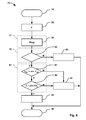
- the method 75 may executed e.g. on the monitoring station 39; the storage element 29 of the third controller 43 of the monitoring station may be programmed accordingly.
- the method 75 comprises a measurement block 77 for determining measurement data describing a frequency dependent function that depends on transmission characteristics of the telecommunication line.
- the method 75 comprises a detection block 79 for detecting resonances. A resonance may be detected if a local minimum (dip) has been found in the frequency dependant function.
- the method 75 comprises an identification block 81 for deciding based on the frequency of at least one local minimum found in the detection block 79 on whether or not the at least one minimum is caused by insufficient balance of the line.
- the frequency range F may correspond to the frequency range occupied by a signal of a DSL variant that is planned to be used in connection with the line.
- the frequency range F may include all frequencies from zero to up to about 30 MHz.
- the upper limit of the frequency range may be e.g. 100 MHz or even 200 MHz. If the operator considers multiple DSL variants as candidates to be deployed, the method 75 may be executed multiple times with different frequency ranges F determined in step 80. After having determined the frequency range F, the method 75 continues with the measurement block 77.
- the measurement block 77 comprises a step 82 of determining measurement data describing a direct transfer function Hlog of the considered line 13, 55. That is, in the shown embodiment, the frequency dependant function is the direct transfer function Hlog and the transmission characteristic is the frequency response of the line 13, 55. Determining the measurement data may include retrieving the measurement data from a node connected directly to the line 13, 55, e. g. from an access node 17, 45 or from a DSL modem 19.
- any other frequency dependent function describing a characteristic of the line 13, 55 may be used.
- measurement data may be determined that are based on a direct measurement of the signal-to-noise ratio SNR or on the crosstalk transfer function instead of the direct transfer function.
- a signal-to-noise ratio SNR also has resonances 71 in case of line unbalance (see curve 67).
- the crosstalk transfer function (curve 63) also has resonances similar to the direct transfer function Hlog. However, the frequencies where the resonances of the crosstalk transfer function occur differ from the frequencies of the resonances of the direct transfer function Hlog.
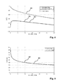
- Figure 9 shows simulation results for the same 500 m lines as in Figure 6 and 7 but on an increased frequency range.
- Figure 9 shows the curve 61 describing the direct transfer function Hlog and the curve 63 describing the crosstalk transfer functionG 12 . Both curves 61, 63 have local minima resulting from resonances but the local minima are located at different frequencies.
- the detection block 79 comprises a step 83 for searching for local minima (dips 71) in the frequency-dependent function described by the measurement data.
- the search may be restricted to frequencies belonging to the frequency range F. If no local minima are detected (N) then a step 85 is executed for detecting that the line 13, 55 is sufficiently balanced.
- the operations of the identification block 81 are performed in order to decide on whether or not the at least one local minimum is caused by insufficient balance of the line 13, 55.
- a bridged-tap on a line 13, 55 may also cause local minima even if the line is perfectly balanced. Therefore, the identification block 81 needs to distinguish local minima caused by a bridged-tap from those caused by a line unbalance.
- a bridged-tap of length L causes periodic local minima in the direct transfer function Hlog at frequencies corresponding to odd multiples of c/(4L BT ).
- f BT 2 ⁇ n + 1 ⁇ c 4 ⁇ L BT
- c the phase velocity of the line
- L BT is the length of the bridged-tap.
- the identification block 81 calculates in a step 87 the length L BT of a hypothetical bridged-tap, preferably from the frequency f 0 of the first local minimum, and compares the calculated length L BT with a threshold min_L BT . If the length L BT of the hypothetical bridged-tap is greater than the threshold min_L BT (Y) then a step 89 is executed. Otherwise (N), a step 91 is executed for determining that the line 13, 55 is insufficiently balanced.
- step 91 is executed and an insufficient line balance is detected.
- the method 75 is terminated after step 85, 91 and 93 in a termination step 94.
- the second step 89 of the identification block 81 allows for distinguishing a bridged-tap from insufficient line balance in cases of longer lines or in case of comparatively strong unbalance.
- the first resonance may appear at a rather low frequency f 0 .
- the solid line 61 shows the direct transfer function Hlog in case of an unbalanced line 13, 55.
- FIG. 13 also shows (dashed line 95) the simulated direct transfer function Hlog for the 500 m line that is perfectly balanced but has a bridged-tap whose length is 1.88m. The positions of the successive local minima in the direct transfer function Hlog are different for these two curves 61, 95. Only curve 95 has local minima f 0 , f E that are located in the frequency domain according to the above-described pattern. Therefore, step 89 of the identification block 81 of the method 75 will identify a bridged tap if the measurement data describe the curve 91 and detect an insufficient balance if the measurement data describe the curve 61.
- the method described herein allows not only for estimating whether a certain telecommunication line 13, 55 is suitable for high bit rate DSL services like VDSL2 or G.Fast but also allows - in case of an unsuitable line - for checking whether the cause of the insufficient quality of the line is the insufficient balance of the line or the presence of a bridged-tap.
- the network operator may remove the bridged-tap and perform the method 75 again on the line with the bridged-tap removed.
- the network operator may conclude that it is unlikely that high bit rate services like VDSL2 or G.Fast can be used on that line and may refrain from installing respective network equipment.
- the method 75 measures the frequency dependent function and detects the local minima in the function. If local minima are present within the frequency band used for VDSL2, the line 13, 55 may not be sufficiently balanced to get a significant gain in terms of maximum bit rate with vectoring, and is not a good candidate for an upgrade to G.Fast. If dips are present above the frequency band used for VDSL2 but within the band used for G.Fast, vectoring could help increasing the line performance or bit rate but the line may not be suitable for G.Fast. If no local minima are present below e. g. 100 MHz or 200 MHz, the line 13, 55 is sufficiently balanced for G.Fast deployment. If local minima are detected, the method allows for deciding on whether or not the removal of a bridged-tap might help to improve the quality of the line 13, 55.
Landscapes
- Engineering & Computer Science (AREA)
- Signal Processing (AREA)
- Computer Networks & Wireless Communication (AREA)
- Cable Transmission Systems, Equalization Of Radio And Reduction Of Echo (AREA)
Priority Applications (1)
| Application Number | Priority Date | Filing Date | Title |
|---|---|---|---|
| EP13305970.9A EP2824844B1 (fr) | 2013-07-08 | 2013-07-08 | Procédé et dispositif pour l'évaluation d'une ligne de télécommunication |
Applications Claiming Priority (1)
| Application Number | Priority Date | Filing Date | Title |
|---|---|---|---|
| EP13305970.9A EP2824844B1 (fr) | 2013-07-08 | 2013-07-08 | Procédé et dispositif pour l'évaluation d'une ligne de télécommunication |
Publications (2)
| Publication Number | Publication Date |
|---|---|
| EP2824844A1 true EP2824844A1 (fr) | 2015-01-14 |
| EP2824844B1 EP2824844B1 (fr) | 2016-09-21 |
Family
ID=48900913
Family Applications (1)
| Application Number | Title | Priority Date | Filing Date |
|---|---|---|---|
| EP13305970.9A Not-in-force EP2824844B1 (fr) | 2013-07-08 | 2013-07-08 | Procédé et dispositif pour l'évaluation d'une ligne de télécommunication |
Country Status (1)
| Country | Link |
|---|---|
| EP (1) | EP2824844B1 (fr) |
Citations (1)
| Publication number | Priority date | Publication date | Assignee | Title |
|---|---|---|---|---|
| US20090225821A1 (en) * | 2008-03-04 | 2009-09-10 | Hua Jiao | Methods and apparatus to detect an imbalanced subscriber line in a digital subscriber line (dsl) system |
-
2013
- 2013-07-08 EP EP13305970.9A patent/EP2824844B1/fr not_active Not-in-force
Patent Citations (1)
| Publication number | Priority date | Publication date | Assignee | Title |
|---|---|---|---|---|
| US20090225821A1 (en) * | 2008-03-04 | 2009-09-10 | Hua Jiao | Methods and apparatus to detect an imbalanced subscriber line in a digital subscriber line (dsl) system |
Non-Patent Citations (2)
| Title |
|---|
| JDSU: "Application Note Detecting Bridged Tap and Noise Interference in VDSL2 Access Networks using the JDSU SmartClass(TM) TPS Test Challenge", 18 May 2011 (2011-05-18), XP055092130, Retrieved from the Internet <URL:http://www.jdsu.com/productliterature/sctpsbridgedtap_an_tfs_tm_ae.pdf> [retrieved on 20131206] * |
| PAVEL LAFATA: "Far-end crosstalk modeling based on capacitive and inductive unbalances between pairs in a cable", INFORMATION AND COMMUNICATION TECHNOLOGIES AND SERVICES, vol. 9, no. 1, March 2011 (2011-03-01) |
Also Published As
| Publication number | Publication date |
|---|---|
| EP2824844B1 (fr) | 2016-09-21 |
Similar Documents
| Publication | Publication Date | Title |
|---|---|---|
| EP1300964B1 (fr) | Système et méthode pour la mesure de la diaphonie dans un resau XDSL | |
| EP1248383B1 (fr) | Procédé et appareil pour l'identification d'un réseau d'accès par mesures monoport | |
| US9485353B2 (en) | Method and device for detecting a bridged tap within a telecommunication line | |
| EP2712160A1 (fr) | Procédé et dispositif pour tester un équipement de locaux d'abonné | |
| EP2824844B1 (fr) | Procédé et dispositif pour l'évaluation d'une ligne de télécommunication | |
| CA2688059C (fr) | Methode et localisateur de detection et de localisation de bobines de charge dans une ligne de transmission | |
| EP2854299B1 (fr) | Procédé et dispositif pour l'analyse d'une ligne de communication | |
| US7113482B1 (en) | Systems and methods for performing DSL loop qualification | |
| EP2945297B1 (fr) | Procédé et dispositif pour estimer un débit binaire réalisable d'une ligne de télécommunication électrique | |
| EP3433937B1 (fr) | Procédé et système pour estimer la diaphonie entre des lignes de transmission électriques | |
| US9608694B2 (en) | Method and device for locating an impairment within a telecommunication line | |
| EP2709345B1 (fr) | Procédés et dispositif pour réduire la diaphonie | |
| EP2073519A1 (fr) | Identification de couples | |
| EP2642735A1 (fr) | Procédé et dispositif pour détecter au moins un branchement en dérivation à l'intérieur d'une ligne de télécommunication | |
| EP2733858B1 (fr) | Procédé et dispositif pour déterminer une valeur de longueur d'une section d'une ligne de télécommunication | |
| WO2002033941A1 (fr) | Procede et dispositif permettant de tester des lignes telephoniques et de donnees dans un systeme de telecommunications |
Legal Events
| Date | Code | Title | Description |
|---|---|---|---|
| 17P | Request for examination filed |
Effective date: 20140303 |
|
| AK | Designated contracting states |
Kind code of ref document: A1 Designated state(s): AL AT BE BG CH CY CZ DE DK EE ES FI FR GB GR HR HU IE IS IT LI LT LU LV MC MK MT NL NO PL PT RO RS SE SI SK SM TR |
|
| AX | Request for extension of the european patent |
Extension state: BA ME |
|
| PUAI | Public reference made under article 153(3) epc to a published international application that has entered the european phase |
Free format text: ORIGINAL CODE: 0009012 |
|
| RBV | Designated contracting states (corrected) |
Designated state(s): AL AT BE BG CH CY CZ DE DK EE ES FI FR GB GR HR HU IE IS IT LI LT LU LV MC MK MT NL NO PL PT RO RS SE SI SK SM TR |
|
| RIC1 | Information provided on ipc code assigned before grant |
Ipc: H04M 3/30 20060101ALN20160323BHEP Ipc: H04B 3/30 20060101ALN20160323BHEP Ipc: H04B 3/46 20060101AFI20160323BHEP |
|
| GRAP | Despatch of communication of intention to grant a patent |
Free format text: ORIGINAL CODE: EPIDOSNIGR1 |
|
| INTG | Intention to grant announced |
Effective date: 20160506 |
|
| GRAS | Grant fee paid |
Free format text: ORIGINAL CODE: EPIDOSNIGR3 |
|
| GRAA | (expected) grant |
Free format text: ORIGINAL CODE: 0009210 |
|
| AK | Designated contracting states |
Kind code of ref document: B1 Designated state(s): AL AT BE BG CH CY CZ DE DK EE ES FI FR GB GR HR HU IE IS IT LI LT LU LV MC MK MT NL NO PL PT RO RS SE SI SK SM TR |
|
| REG | Reference to a national code |
Ref country code: GB Ref legal event code: FG4D |
|
| REG | Reference to a national code |
Ref country code: CH Ref legal event code: EP |
|
| REG | Reference to a national code |
Ref country code: AT Ref legal event code: REF Ref document number: 831772 Country of ref document: AT Kind code of ref document: T Effective date: 20161015 |
|
| REG | Reference to a national code |
Ref country code: IE Ref legal event code: FG4D |
|
| REG | Reference to a national code |
Ref country code: DE Ref legal event code: R096 Ref document number: 602013011808 Country of ref document: DE |
|
| REG | Reference to a national code |
Ref country code: LT Ref legal event code: MG4D Ref country code: NL Ref legal event code: MP Effective date: 20160921 |
|
| PG25 | Lapsed in a contracting state [announced via postgrant information from national office to epo] |
Ref country code: LT Free format text: LAPSE BECAUSE OF FAILURE TO SUBMIT A TRANSLATION OF THE DESCRIPTION OR TO PAY THE FEE WITHIN THE PRESCRIBED TIME-LIMIT Effective date: 20160921 Ref country code: RS Free format text: LAPSE BECAUSE OF FAILURE TO SUBMIT A TRANSLATION OF THE DESCRIPTION OR TO PAY THE FEE WITHIN THE PRESCRIBED TIME-LIMIT Effective date: 20160921 Ref country code: NO Free format text: LAPSE BECAUSE OF FAILURE TO SUBMIT A TRANSLATION OF THE DESCRIPTION OR TO PAY THE FEE WITHIN THE PRESCRIBED TIME-LIMIT Effective date: 20161221 Ref country code: FI Free format text: LAPSE BECAUSE OF FAILURE TO SUBMIT A TRANSLATION OF THE DESCRIPTION OR TO PAY THE FEE WITHIN THE PRESCRIBED TIME-LIMIT Effective date: 20160921 |
|
| REG | Reference to a national code |
Ref country code: AT Ref legal event code: MK05 Ref document number: 831772 Country of ref document: AT Kind code of ref document: T Effective date: 20160921 |
|
| PG25 | Lapsed in a contracting state [announced via postgrant information from national office to epo] |
Ref country code: GR Free format text: LAPSE BECAUSE OF FAILURE TO SUBMIT A TRANSLATION OF THE DESCRIPTION OR TO PAY THE FEE WITHIN THE PRESCRIBED TIME-LIMIT Effective date: 20161222 Ref country code: LV Free format text: LAPSE BECAUSE OF FAILURE TO SUBMIT A TRANSLATION OF THE DESCRIPTION OR TO PAY THE FEE WITHIN THE PRESCRIBED TIME-LIMIT Effective date: 20160921 Ref country code: NL Free format text: LAPSE BECAUSE OF FAILURE TO SUBMIT A TRANSLATION OF THE DESCRIPTION OR TO PAY THE FEE WITHIN THE PRESCRIBED TIME-LIMIT Effective date: 20160921 Ref country code: SE Free format text: LAPSE BECAUSE OF FAILURE TO SUBMIT A TRANSLATION OF THE DESCRIPTION OR TO PAY THE FEE WITHIN THE PRESCRIBED TIME-LIMIT Effective date: 20160921 |
|
| PG25 | Lapsed in a contracting state [announced via postgrant information from national office to epo] |
Ref country code: RO Free format text: LAPSE BECAUSE OF FAILURE TO SUBMIT A TRANSLATION OF THE DESCRIPTION OR TO PAY THE FEE WITHIN THE PRESCRIBED TIME-LIMIT Effective date: 20160921 Ref country code: EE Free format text: LAPSE BECAUSE OF FAILURE TO SUBMIT A TRANSLATION OF THE DESCRIPTION OR TO PAY THE FEE WITHIN THE PRESCRIBED TIME-LIMIT Effective date: 20160921 |
|
| PG25 | Lapsed in a contracting state [announced via postgrant information from national office to epo] |
Ref country code: ES Free format text: LAPSE BECAUSE OF FAILURE TO SUBMIT A TRANSLATION OF THE DESCRIPTION OR TO PAY THE FEE WITHIN THE PRESCRIBED TIME-LIMIT Effective date: 20160921 Ref country code: AT Free format text: LAPSE BECAUSE OF FAILURE TO SUBMIT A TRANSLATION OF THE DESCRIPTION OR TO PAY THE FEE WITHIN THE PRESCRIBED TIME-LIMIT Effective date: 20160921 Ref country code: SK Free format text: LAPSE BECAUSE OF FAILURE TO SUBMIT A TRANSLATION OF THE DESCRIPTION OR TO PAY THE FEE WITHIN THE PRESCRIBED TIME-LIMIT Effective date: 20160921 Ref country code: SM Free format text: LAPSE BECAUSE OF FAILURE TO SUBMIT A TRANSLATION OF THE DESCRIPTION OR TO PAY THE FEE WITHIN THE PRESCRIBED TIME-LIMIT Effective date: 20160921 Ref country code: PT Free format text: LAPSE BECAUSE OF FAILURE TO SUBMIT A TRANSLATION OF THE DESCRIPTION OR TO PAY THE FEE WITHIN THE PRESCRIBED TIME-LIMIT Effective date: 20170123 Ref country code: IS Free format text: LAPSE BECAUSE OF FAILURE TO SUBMIT A TRANSLATION OF THE DESCRIPTION OR TO PAY THE FEE WITHIN THE PRESCRIBED TIME-LIMIT Effective date: 20170121 Ref country code: CZ Free format text: LAPSE BECAUSE OF FAILURE TO SUBMIT A TRANSLATION OF THE DESCRIPTION OR TO PAY THE FEE WITHIN THE PRESCRIBED TIME-LIMIT Effective date: 20160921 Ref country code: BE Free format text: LAPSE BECAUSE OF FAILURE TO SUBMIT A TRANSLATION OF THE DESCRIPTION OR TO PAY THE FEE WITHIN THE PRESCRIBED TIME-LIMIT Effective date: 20160921 Ref country code: PL Free format text: LAPSE BECAUSE OF FAILURE TO SUBMIT A TRANSLATION OF THE DESCRIPTION OR TO PAY THE FEE WITHIN THE PRESCRIBED TIME-LIMIT Effective date: 20160921 Ref country code: BG Free format text: LAPSE BECAUSE OF FAILURE TO SUBMIT A TRANSLATION OF THE DESCRIPTION OR TO PAY THE FEE WITHIN THE PRESCRIBED TIME-LIMIT Effective date: 20161221 |
|
| REG | Reference to a national code |
Ref country code: DE Ref legal event code: R097 Ref document number: 602013011808 Country of ref document: DE |
|
| PG25 | Lapsed in a contracting state [announced via postgrant information from national office to epo] |
Ref country code: IT Free format text: LAPSE BECAUSE OF FAILURE TO SUBMIT A TRANSLATION OF THE DESCRIPTION OR TO PAY THE FEE WITHIN THE PRESCRIBED TIME-LIMIT Effective date: 20160921 |
|
| REG | Reference to a national code |
Ref country code: FR Ref legal event code: PLFP Year of fee payment: 5 |
|
| PLBE | No opposition filed within time limit |
Free format text: ORIGINAL CODE: 0009261 |
|
| STAA | Information on the status of an ep patent application or granted ep patent |
Free format text: STATUS: NO OPPOSITION FILED WITHIN TIME LIMIT |
|
| PG25 | Lapsed in a contracting state [announced via postgrant information from national office to epo] |
Ref country code: DK Free format text: LAPSE BECAUSE OF FAILURE TO SUBMIT A TRANSLATION OF THE DESCRIPTION OR TO PAY THE FEE WITHIN THE PRESCRIBED TIME-LIMIT Effective date: 20160921 |
|
| 26N | No opposition filed |
Effective date: 20170622 |
|
| PGFP | Annual fee paid to national office [announced via postgrant information from national office to epo] |
Ref country code: FR Payment date: 20170724 Year of fee payment: 5 Ref country code: GB Payment date: 20170719 Year of fee payment: 5 Ref country code: DE Payment date: 20170724 Year of fee payment: 5 |
|
| PG25 | Lapsed in a contracting state [announced via postgrant information from national office to epo] |
Ref country code: SI Free format text: LAPSE BECAUSE OF FAILURE TO SUBMIT A TRANSLATION OF THE DESCRIPTION OR TO PAY THE FEE WITHIN THE PRESCRIBED TIME-LIMIT Effective date: 20160921 |
|
| REG | Reference to a national code |
Ref country code: CH Ref legal event code: PL |
|
| REG | Reference to a national code |
Ref country code: IE Ref legal event code: MM4A |
|
| PG25 | Lapsed in a contracting state [announced via postgrant information from national office to epo] |
Ref country code: CH Free format text: LAPSE BECAUSE OF NON-PAYMENT OF DUE FEES Effective date: 20170731 Ref country code: LI Free format text: LAPSE BECAUSE OF NON-PAYMENT OF DUE FEES Effective date: 20170731 Ref country code: IE Free format text: LAPSE BECAUSE OF NON-PAYMENT OF DUE FEES Effective date: 20170708 |
|
| PG25 | Lapsed in a contracting state [announced via postgrant information from national office to epo] |
Ref country code: LU Free format text: LAPSE BECAUSE OF NON-PAYMENT OF DUE FEES Effective date: 20170708 |
|
| PG25 | Lapsed in a contracting state [announced via postgrant information from national office to epo] |
Ref country code: MT Free format text: LAPSE BECAUSE OF NON-PAYMENT OF DUE FEES Effective date: 20170708 |
|
| PG25 | Lapsed in a contracting state [announced via postgrant information from national office to epo] |
Ref country code: AL Free format text: LAPSE BECAUSE OF FAILURE TO SUBMIT A TRANSLATION OF THE DESCRIPTION OR TO PAY THE FEE WITHIN THE PRESCRIBED TIME-LIMIT Effective date: 20160921 |
|
| REG | Reference to a national code |
Ref country code: DE Ref legal event code: R119 Ref document number: 602013011808 Country of ref document: DE |
|
| GBPC | Gb: european patent ceased through non-payment of renewal fee |
Effective date: 20180708 |
|
| PG25 | Lapsed in a contracting state [announced via postgrant information from national office to epo] |
Ref country code: GB Free format text: LAPSE BECAUSE OF NON-PAYMENT OF DUE FEES Effective date: 20180708 Ref country code: FR Free format text: LAPSE BECAUSE OF NON-PAYMENT OF DUE FEES Effective date: 20180731 Ref country code: DE Free format text: LAPSE BECAUSE OF NON-PAYMENT OF DUE FEES Effective date: 20190201 |
|
| REG | Reference to a national code |
Ref country code: GB Ref legal event code: 732E Free format text: REGISTERED BETWEEN 20190418 AND 20190426 |
|
| PG25 | Lapsed in a contracting state [announced via postgrant information from national office to epo] |
Ref country code: MC Free format text: LAPSE BECAUSE OF FAILURE TO SUBMIT A TRANSLATION OF THE DESCRIPTION OR TO PAY THE FEE WITHIN THE PRESCRIBED TIME-LIMIT Effective date: 20160921 Ref country code: HU Free format text: LAPSE BECAUSE OF FAILURE TO SUBMIT A TRANSLATION OF THE DESCRIPTION OR TO PAY THE FEE WITHIN THE PRESCRIBED TIME-LIMIT; INVALID AB INITIO Effective date: 20130708 |
|
| PG25 | Lapsed in a contracting state [announced via postgrant information from national office to epo] |
Ref country code: CY Free format text: LAPSE BECAUSE OF FAILURE TO SUBMIT A TRANSLATION OF THE DESCRIPTION OR TO PAY THE FEE WITHIN THE PRESCRIBED TIME-LIMIT Effective date: 20160921 |
|
| PG25 | Lapsed in a contracting state [announced via postgrant information from national office to epo] |
Ref country code: MK Free format text: LAPSE BECAUSE OF FAILURE TO SUBMIT A TRANSLATION OF THE DESCRIPTION OR TO PAY THE FEE WITHIN THE PRESCRIBED TIME-LIMIT Effective date: 20160921 |
|
| PG25 | Lapsed in a contracting state [announced via postgrant information from national office to epo] |
Ref country code: TR Free format text: LAPSE BECAUSE OF FAILURE TO SUBMIT A TRANSLATION OF THE DESCRIPTION OR TO PAY THE FEE WITHIN THE PRESCRIBED TIME-LIMIT Effective date: 20160921 |
|
| PG25 | Lapsed in a contracting state [announced via postgrant information from national office to epo] |
Ref country code: HR Free format text: LAPSE BECAUSE OF FAILURE TO SUBMIT A TRANSLATION OF THE DESCRIPTION OR TO PAY THE FEE WITHIN THE PRESCRIBED TIME-LIMIT Effective date: 20160921 |