EP2823837A1 - Autoinjector - Google Patents
Autoinjector Download PDFInfo
- Publication number
- EP2823837A1 EP2823837A1 EP13175660.3A EP13175660A EP2823837A1 EP 2823837 A1 EP2823837 A1 EP 2823837A1 EP 13175660 A EP13175660 A EP 13175660A EP 2823837 A1 EP2823837 A1 EP 2823837A1
- Authority
- EP
- European Patent Office
- Prior art keywords
- autoinjector
- boss
- case
- syringe carrier
- shroud
- Prior art date
- Legal status (The legal status is an assumption and is not a legal conclusion. Google has not performed a legal analysis and makes no representation as to the accuracy of the status listed.)
- Withdrawn
Links
- 229940090047 auto-injector Drugs 0.000 title claims abstract description 66
- 230000007246 mechanism Effects 0.000 claims description 23
- JUFFVKRROAPVBI-PVOYSMBESA-N chembl1210015 Chemical compound C([C@@H](C(=O)N[C@@H]([C@@H](C)CC)C(=O)N[C@@H](CCC(O)=O)C(=O)N[C@@H](CC=1C2=CC=CC=C2NC=1)C(=O)N[C@@H](CC(C)C)C(=O)N[C@@H](CCCCN)C(=O)N[C@@H](CC(=O)N[C@H]1[C@@H]([C@@H](O)[C@H](O[C@H]2[C@@H]([C@@H](O)[C@@H](O)[C@@H](CO[C@]3(O[C@@H](C[C@H](O)[C@H](O)CO)[C@H](NC(C)=O)[C@@H](O)C3)C(O)=O)O2)O)[C@@H](CO)O1)NC(C)=O)C(=O)NCC(=O)NCC(=O)N1[C@@H](CCC1)C(=O)N[C@@H](CO)C(=O)N[C@@H](CO)C(=O)NCC(=O)N[C@@H](C)C(=O)N1[C@@H](CCC1)C(=O)N1[C@@H](CCC1)C(=O)N1[C@@H](CCC1)C(=O)N[C@@H](CO)C(N)=O)NC(=O)[C@H](CC(C)C)NC(=O)[C@H](CCCNC(N)=N)NC(=O)[C@@H](NC(=O)[C@H](C)NC(=O)[C@H](CCC(O)=O)NC(=O)[C@H](CCC(O)=O)NC(=O)[C@H](CCC(O)=O)NC(=O)[C@H](CCSC)NC(=O)[C@H](CCC(N)=O)NC(=O)[C@H](CCCCN)NC(=O)[C@H](CO)NC(=O)[C@H](CC(C)C)NC(=O)[C@H](CC(O)=O)NC(=O)[C@H](CO)NC(=O)[C@@H](NC(=O)[C@H](CC=1C=CC=CC=1)NC(=O)[C@@H](NC(=O)CNC(=O)[C@H](CCC(O)=O)NC(=O)CNC(=O)[C@@H](N)CC=1NC=NC=1)[C@@H](C)O)[C@@H](C)O)C(C)C)C1=CC=CC=C1 JUFFVKRROAPVBI-PVOYSMBESA-N 0.000 description 54
- 108010011459 Exenatide Proteins 0.000 description 50
- 229960001519 exenatide Drugs 0.000 description 50
- 238000002347 injection Methods 0.000 description 24
- 239000007924 injection Substances 0.000 description 24
- 101000976075 Homo sapiens Insulin Proteins 0.000 description 22
- QEFRNWWLZKMPFJ-YGVKFDHGSA-N L-methionine S-oxide Chemical compound CS(=O)CC[C@H](N)C(O)=O QEFRNWWLZKMPFJ-YGVKFDHGSA-N 0.000 description 22
- PBGKTOXHQIOBKM-FHFVDXKLSA-N insulin (human) Chemical compound C([C@@H](C(=O)N[C@@H](CC(C)C)C(=O)N[C@H]1CSSC[C@H]2C(=O)N[C@H](C(=O)N[C@@H](CO)C(=O)N[C@H](C(=O)N[C@H](C(N[C@@H](CO)C(=O)N[C@@H](CC(C)C)C(=O)N[C@@H](CC=3C=CC(O)=CC=3)C(=O)N[C@@H](CCC(N)=O)C(=O)N[C@@H](CC(C)C)C(=O)N[C@@H](CCC(O)=O)C(=O)N[C@@H](CC(N)=O)C(=O)N[C@@H](CC=3C=CC(O)=CC=3)C(=O)N[C@@H](CSSC[C@H](NC(=O)[C@H](C(C)C)NC(=O)[C@H](CC(C)C)NC(=O)[C@H](CC=3C=CC(O)=CC=3)NC(=O)[C@H](CC(C)C)NC(=O)[C@H](C)NC(=O)[C@H](CCC(O)=O)NC(=O)[C@H](C(C)C)NC(=O)[C@H](CC(C)C)NC(=O)[C@H](CC=3NC=NC=3)NC(=O)[C@H](CO)NC(=O)CNC1=O)C(=O)NCC(=O)N[C@@H](CCC(O)=O)C(=O)N[C@@H](CCCNC(N)=N)C(=O)NCC(=O)N[C@@H](CC=1C=CC=CC=1)C(=O)N[C@@H](CC=1C=CC=CC=1)C(=O)N[C@@H](CC=1C=CC(O)=CC=1)C(=O)N[C@@H]([C@@H](C)O)C(=O)N1[C@@H](CCC1)C(=O)N[C@@H](CCCCN)C(=O)N[C@@H]([C@@H](C)O)C(O)=O)C(=O)N[C@@H](CC(N)=O)C(O)=O)=O)CSSC[C@@H](C(N2)=O)NC(=O)[C@H](CCC(N)=O)NC(=O)[C@H](CCC(O)=O)NC(=O)[C@H](C(C)C)NC(=O)[C@@H](NC(=O)CN)[C@@H](C)CC)[C@@H](C)CC)[C@@H](C)O)NC(=O)[C@H](CCC(N)=O)NC(=O)[C@H](CC(N)=O)NC(=O)[C@@H](NC(=O)[C@@H](N)CC=1C=CC=CC=1)C(C)C)C1=CN=CN1 PBGKTOXHQIOBKM-FHFVDXKLSA-N 0.000 description 21
- 239000003814 drug Substances 0.000 description 11
- 238000003780 insertion Methods 0.000 description 11
- 230000037431 insertion Effects 0.000 description 11
- 239000012634 fragment Substances 0.000 description 10
- 235000001014 amino acid Nutrition 0.000 description 9
- 150000001413 amino acids Chemical class 0.000 description 9
- 150000003839 salts Chemical class 0.000 description 8
- 239000000427 antigen Substances 0.000 description 7
- 102000036639 antigens Human genes 0.000 description 7
- 108091007433 antigens Proteins 0.000 description 7
- 150000001875 compounds Chemical class 0.000 description 7
- 230000000994 depressogenic effect Effects 0.000 description 7
- 108090000765 processed proteins & peptides Proteins 0.000 description 5
- 108060003951 Immunoglobulin Proteins 0.000 description 4
- 206010012601 diabetes mellitus Diseases 0.000 description 4
- 102000018358 immunoglobulin Human genes 0.000 description 4
- 108010047041 Complementarity Determining Regions Proteins 0.000 description 3
- 238000007792 addition Methods 0.000 description 3
- 210000003719 b-lymphocyte Anatomy 0.000 description 3
- 150000004676 glycans Chemical class 0.000 description 3
- 229940088597 hormone Drugs 0.000 description 3
- 239000005556 hormone Substances 0.000 description 3
- NOESYZHRGYRDHS-UHFFFAOYSA-N insulin Chemical class N1C(=O)C(NC(=O)C(CCC(N)=O)NC(=O)C(CCC(O)=O)NC(=O)C(C(C)C)NC(=O)C(NC(=O)CN)C(C)CC)CSSCC(C(NC(CO)C(=O)NC(CC(C)C)C(=O)NC(CC=2C=CC(O)=CC=2)C(=O)NC(CCC(N)=O)C(=O)NC(CC(C)C)C(=O)NC(CCC(O)=O)C(=O)NC(CC(N)=O)C(=O)NC(CC=2C=CC(O)=CC=2)C(=O)NC(CSSCC(NC(=O)C(C(C)C)NC(=O)C(CC(C)C)NC(=O)C(CC=2C=CC(O)=CC=2)NC(=O)C(CC(C)C)NC(=O)C(C)NC(=O)C(CCC(O)=O)NC(=O)C(C(C)C)NC(=O)C(CC(C)C)NC(=O)C(CC=2NC=NC=2)NC(=O)C(CO)NC(=O)CNC2=O)C(=O)NCC(=O)NC(CCC(O)=O)C(=O)NC(CCCNC(N)=N)C(=O)NCC(=O)NC(CC=3C=CC=CC=3)C(=O)NC(CC=3C=CC=CC=3)C(=O)NC(CC=3C=CC(O)=CC=3)C(=O)NC(C(C)O)C(=O)N3C(CCC3)C(=O)NC(CCCCN)C(=O)NC(C)C(O)=O)C(=O)NC(CC(N)=O)C(O)=O)=O)NC(=O)C(C(C)CC)NC(=O)C(CO)NC(=O)C(C(C)O)NC(=O)C1CSSCC2NC(=O)C(CC(C)C)NC(=O)C(NC(=O)C(CCC(N)=O)NC(=O)C(CC(N)=O)NC(=O)C(NC(=O)C(N)CC=1C=CC=CC=1)C(C)C)CC1=CN=CN1 NOESYZHRGYRDHS-UHFFFAOYSA-N 0.000 description 3
- 239000003055 low molecular weight heparin Substances 0.000 description 3
- 229940127215 low-molecular weight heparin Drugs 0.000 description 3
- 238000012986 modification Methods 0.000 description 3
- 230000004048 modification Effects 0.000 description 3
- 229920001282 polysaccharide Polymers 0.000 description 3
- 239000005017 polysaccharide Substances 0.000 description 3
- 230000001681 protective effect Effects 0.000 description 3
- 208000004476 Acute Coronary Syndrome Diseases 0.000 description 2
- 208000002249 Diabetes Complications Diseases 0.000 description 2
- 206010012689 Diabetic retinopathy Diseases 0.000 description 2
- 108010088406 Glucagon-Like Peptides Proteins 0.000 description 2
- 241000124008 Mammalia Species 0.000 description 2
- 239000002253 acid Substances 0.000 description 2
- 150000001447 alkali salts Chemical class 0.000 description 2
- 125000000151 cysteine group Chemical group N[C@@H](CS)C(=O)* 0.000 description 2
- 238000013461 design Methods 0.000 description 2
- 230000029087 digestion Effects 0.000 description 2
- LMHMJYMCGJNXRS-IOPUOMRJSA-N exendin-3 Chemical compound C([C@@H](C(=O)N[C@@H]([C@@H](C)CC)C(=O)N[C@@H](CCC(O)=O)C(=O)N[C@@H](CC=1C2=CC=CC=C2NC=1)C(=O)N[C@@H](CC(C)C)C(=O)N[C@@H](CCCCN)C(=O)N[C@@H](CC(N)=O)C(=O)NCC(=O)NCC(=O)N1[C@@H](CCC1)C(=O)N[C@@H](CO)C(=O)N[C@@H](CO)C(=O)NCC(=O)N[C@@H](C)C(=O)N1[C@@H](CCC1)C(=O)N1[C@@H](CCC1)C(=O)N1[C@@H](CCC1)C(=O)N[C@@H](CO)C(N)=O)NC(=O)[C@H](CC(C)C)NC(=O)[C@H](CCCNC(N)=N)NC(=O)[C@@H](NC(=O)[C@H](C)NC(=O)[C@H](CCC(O)=O)NC(=O)[C@H](CCC(O)=O)NC(=O)[C@H](CCC(O)=O)NC(=O)[C@H](CCSC)NC(=O)[C@H](CCC(N)=O)NC(=O)[C@H](CCCCN)NC(=O)[C@H](CO)NC(=O)[C@H](CC(C)C)NC(=O)[C@H](CC(O)=O)NC(=O)[C@H](CO)NC(=O)[C@@H](NC(=O)[C@H](CC=1C=CC=CC=1)NC(=O)[C@@H](NC(=O)CNC(=O)[C@H](CC(O)=O)NC(=O)[C@H](CO)NC(=O)[C@@H](N)CC=1N=CNC=1)[C@H](C)O)[C@H](C)O)C(C)C)C1=CC=CC=C1 LMHMJYMCGJNXRS-IOPUOMRJSA-N 0.000 description 2
- 239000007788 liquid Substances 0.000 description 2
- 238000000034 method Methods 0.000 description 2
- 239000000203 mixture Substances 0.000 description 2
- 239000000178 monomer Substances 0.000 description 2
- 102000004196 processed proteins & peptides Human genes 0.000 description 2
- 238000011321 prophylaxis Methods 0.000 description 2
- 239000012453 solvate Substances 0.000 description 2
- 238000011282 treatment Methods 0.000 description 2
- 230000000007 visual effect Effects 0.000 description 2
- KIUKXJAPPMFGSW-DNGZLQJQSA-N (2S,3S,4S,5R,6R)-6-[(2S,3R,4R,5S,6R)-3-Acetamido-2-[(2S,3S,4R,5R,6R)-6-[(2R,3R,4R,5S,6R)-3-acetamido-2,5-dihydroxy-6-(hydroxymethyl)oxan-4-yl]oxy-2-carboxy-4,5-dihydroxyoxan-3-yl]oxy-5-hydroxy-6-(hydroxymethyl)oxan-4-yl]oxy-3,4,5-trihydroxyoxane-2-carboxylic acid Chemical compound CC(=O)N[C@H]1[C@H](O)O[C@H](CO)[C@@H](O)[C@@H]1O[C@H]1[C@H](O)[C@@H](O)[C@H](O[C@H]2[C@@H]([C@@H](O[C@H]3[C@@H]([C@@H](O)[C@H](O)[C@H](O3)C(O)=O)O)[C@H](O)[C@@H](CO)O2)NC(C)=O)[C@@H](C(O)=O)O1 KIUKXJAPPMFGSW-DNGZLQJQSA-N 0.000 description 1
- 125000004169 (C1-C6) alkyl group Chemical group 0.000 description 1
- 125000001831 (C6-C10) heteroaryl group Chemical group 0.000 description 1
- 208000035285 Allergic Seasonal Rhinitis Diseases 0.000 description 1
- QGZKDVFQNNGYKY-UHFFFAOYSA-O Ammonium Chemical compound [NH4+] QGZKDVFQNNGYKY-UHFFFAOYSA-O 0.000 description 1
- 206010002383 Angina Pectoris Diseases 0.000 description 1
- 201000001320 Atherosclerosis Diseases 0.000 description 1
- 108010017384 Blood Proteins Proteins 0.000 description 1
- 102000004506 Blood Proteins Human genes 0.000 description 1
- 108010037003 Buserelin Proteins 0.000 description 1
- 125000000882 C2-C6 alkenyl group Chemical group 0.000 description 1
- 125000000041 C6-C10 aryl group Chemical group 0.000 description 1
- 108010000437 Deamino Arginine Vasopressin Proteins 0.000 description 1
- 208000005189 Embolism Diseases 0.000 description 1
- 108090000790 Enzymes Proteins 0.000 description 1
- 102000004190 Enzymes Human genes 0.000 description 1
- 102000012673 Follicle Stimulating Hormone Human genes 0.000 description 1
- 108010079345 Follicle Stimulating Hormone Proteins 0.000 description 1
- 102000003886 Glycoproteins Human genes 0.000 description 1
- 108090000288 Glycoproteins Proteins 0.000 description 1
- 102400000932 Gonadoliberin-1 Human genes 0.000 description 1
- 108010069236 Goserelin Proteins 0.000 description 1
- BLCLNMBMMGCOAS-URPVMXJPSA-N Goserelin Chemical compound C([C@@H](C(=O)N[C@H](COC(C)(C)C)C(=O)N[C@@H](CC(C)C)C(=O)N[C@@H](CCCN=C(N)N)C(=O)N1[C@@H](CCC1)C(=O)NNC(N)=O)NC(=O)[C@H](CO)NC(=O)[C@H](CC=1C2=CC=CC=C2NC=1)NC(=O)[C@H](CC=1NC=NC=1)NC(=O)[C@H]1NC(=O)CC1)C1=CC=C(O)C=C1 BLCLNMBMMGCOAS-URPVMXJPSA-N 0.000 description 1
- HTTJABKRGRZYRN-UHFFFAOYSA-N Heparin Chemical compound OC1C(NC(=O)C)C(O)OC(COS(O)(=O)=O)C1OC1C(OS(O)(=O)=O)C(O)C(OC2C(C(OS(O)(=O)=O)C(OC3C(C(O)C(O)C(O3)C(O)=O)OS(O)(=O)=O)C(CO)O2)NS(O)(=O)=O)C(C(O)=O)O1 HTTJABKRGRZYRN-UHFFFAOYSA-N 0.000 description 1
- 101500026183 Homo sapiens Gonadoliberin-1 Proteins 0.000 description 1
- 102000002265 Human Growth Hormone Human genes 0.000 description 1
- 108010000521 Human Growth Hormone Proteins 0.000 description 1
- 239000000854 Human Growth Hormone Substances 0.000 description 1
- 108010021625 Immunoglobulin Fragments Proteins 0.000 description 1
- 102000008394 Immunoglobulin Fragments Human genes 0.000 description 1
- 102000013463 Immunoglobulin Light Chains Human genes 0.000 description 1
- 108010065825 Immunoglobulin Light Chains Proteins 0.000 description 1
- 206010061218 Inflammation Diseases 0.000 description 1
- 108090001061 Insulin Proteins 0.000 description 1
- 102000004877 Insulin Human genes 0.000 description 1
- 108010000817 Leuprolide Proteins 0.000 description 1
- 102000009151 Luteinizing Hormone Human genes 0.000 description 1
- 108010073521 Luteinizing Hormone Proteins 0.000 description 1
- 108010021717 Nafarelin Proteins 0.000 description 1
- 206010028980 Neoplasm Diseases 0.000 description 1
- 108091034117 Oligonucleotide Proteins 0.000 description 1
- 108090000526 Papain Proteins 0.000 description 1
- 102000057297 Pepsin A Human genes 0.000 description 1
- 108090000284 Pepsin A Proteins 0.000 description 1
- ONIBWKKTOPOVIA-UHFFFAOYSA-N Proline Natural products OC(=O)C1CCCN1 ONIBWKKTOPOVIA-UHFFFAOYSA-N 0.000 description 1
- 239000004365 Protease Substances 0.000 description 1
- 208000010378 Pulmonary Embolism Diseases 0.000 description 1
- 108010010056 Terlipressin Proteins 0.000 description 1
- 208000001435 Thromboembolism Diseases 0.000 description 1
- 108010050144 Triptorelin Pamoate Proteins 0.000 description 1
- 239000003513 alkali Substances 0.000 description 1
- 125000000539 amino acid group Chemical group 0.000 description 1
- 239000005557 antagonist Substances 0.000 description 1
- 238000013459 approach Methods 0.000 description 1
- 230000002917 arthritic effect Effects 0.000 description 1
- 230000008901 benefit Effects 0.000 description 1
- 229960002719 buserelin Drugs 0.000 description 1
- CUWODFFVMXJOKD-UVLQAERKSA-N buserelin Chemical compound CCNC(=O)[C@@H]1CCCN1C(=O)[C@H](CCCN=C(N)N)NC(=O)[C@H](CC(C)C)NC(=O)[C@@H](COC(C)(C)C)NC(=O)[C@@H](NC(=O)[C@H](CO)NC(=O)[C@H](CC=1C2=CC=CC=C2NC=1)NC(=O)[C@H](CC=1NC=NC=1)NC(=O)[C@H]1NC(=O)CC1)CC1=CC=C(O)C=C1 CUWODFFVMXJOKD-UVLQAERKSA-N 0.000 description 1
- 201000011510 cancer Diseases 0.000 description 1
- 150000001720 carbohydrates Chemical class 0.000 description 1
- 235000014633 carbohydrates Nutrition 0.000 description 1
- 125000003178 carboxy group Chemical group [H]OC(*)=O 0.000 description 1
- 150000001768 cations Chemical class 0.000 description 1
- 230000000295 complement effect Effects 0.000 description 1
- 238000007906 compression Methods 0.000 description 1
- 230000006835 compression Effects 0.000 description 1
- 230000008878 coupling Effects 0.000 description 1
- 238000010168 coupling process Methods 0.000 description 1
- 238000005859 coupling reaction Methods 0.000 description 1
- 235000018417 cysteine Nutrition 0.000 description 1
- 229960004281 desmopressin Drugs 0.000 description 1
- NFLWUMRGJYTJIN-NXBWRCJVSA-N desmopressin Chemical compound C([C@H]1C(=O)N[C@H](C(N[C@@H](CC(N)=O)C(=O)N[C@@H](CSSCCC(=O)N[C@@H](CC=2C=CC(O)=CC=2)C(=O)N1)C(=O)N1[C@@H](CCC1)C(=O)N[C@@H](CCCNC(N)=N)C(=O)NCC(N)=O)=O)CCC(=O)N)C1=CC=CC=C1 NFLWUMRGJYTJIN-NXBWRCJVSA-N 0.000 description 1
- 208000037265 diseases, disorders, signs and symptoms Diseases 0.000 description 1
- 208000035475 disorder Diseases 0.000 description 1
- 229940079593 drug Drugs 0.000 description 1
- 238000005516 engineering process Methods 0.000 description 1
- 229960005153 enoxaparin sodium Drugs 0.000 description 1
- 229940088598 enzyme Drugs 0.000 description 1
- 108010015174 exendin 3 Proteins 0.000 description 1
- 239000012530 fluid Substances 0.000 description 1
- 229960001442 gonadorelin Drugs 0.000 description 1
- XLXSAKCOAKORKW-AQJXLSMYSA-N gonadorelin Chemical compound C([C@@H](C(=O)NCC(=O)N[C@@H](CC(C)C)C(=O)N[C@@H](CCCNC(N)=N)C(=O)N1[C@@H](CCC1)C(=O)NCC(N)=O)NC(=O)[C@H](CO)NC(=O)[C@H](CC=1C2=CC=CC=C2NC=1)NC(=O)[C@H](CC=1N=CNC=1)NC(=O)[C@H]1NC(=O)CC1)C1=CC=C(O)C=C1 XLXSAKCOAKORKW-AQJXLSMYSA-N 0.000 description 1
- 229960002913 goserelin Drugs 0.000 description 1
- 229960002897 heparin Drugs 0.000 description 1
- 229920000669 heparin Polymers 0.000 description 1
- 229920002674 hyaluronan Polymers 0.000 description 1
- 229960003160 hyaluronic acid Drugs 0.000 description 1
- 150000004677 hydrates Chemical class 0.000 description 1
- 229910052739 hydrogen Inorganic materials 0.000 description 1
- 239000001257 hydrogen Substances 0.000 description 1
- 125000004435 hydrogen atom Chemical class [H]* 0.000 description 1
- 239000000960 hypophysis hormone Substances 0.000 description 1
- 210000003016 hypothalamus Anatomy 0.000 description 1
- 229940072221 immunoglobulins Drugs 0.000 description 1
- 230000004054 inflammatory process Effects 0.000 description 1
- 229940125396 insulin Drugs 0.000 description 1
- 239000004026 insulin derivative Substances 0.000 description 1
- 230000003993 interaction Effects 0.000 description 1
- GFIJNRVAKGFPGQ-LIJARHBVSA-N leuprolide Chemical compound CCNC(=O)[C@@H]1CCCN1C(=O)[C@H](CCCNC(N)=N)NC(=O)[C@H](CC(C)C)NC(=O)[C@@H](CC(C)C)NC(=O)[C@@H](NC(=O)[C@H](CO)NC(=O)[C@H](CC=1C2=CC=CC=C2NC=1)NC(=O)[C@H](CC=1N=CNC=1)NC(=O)[C@H]1NC(=O)CC1)CC1=CC=C(O)C=C1 GFIJNRVAKGFPGQ-LIJARHBVSA-N 0.000 description 1
- 229960004338 leuprorelin Drugs 0.000 description 1
- XVVOERDUTLJJHN-IAEQDCLQSA-N lixisenatide Chemical compound C([C@@H](C(=O)N[C@@H]([C@@H](C)CC)C(=O)N[C@@H](CCC(O)=O)C(=O)N[C@@H](CC=1C2=CC=CC=C2NC=1)C(=O)N[C@@H](CC(C)C)C(=O)N[C@@H](CCCCN)C(=O)N[C@@H](CC(N)=O)C(=O)NCC(=O)NCC(=O)N1[C@@H](CCC1)C(=O)N[C@@H](CO)C(=O)N[C@@H](CO)C(=O)NCC(=O)N[C@@H](C)C(=O)N1[C@@H](CCC1)C(=O)N1[C@@H](CCC1)C(=O)N[C@@H](CO)C(=O)N[C@@H](CCCCN)C(=O)N[C@@H](CCCCN)C(=O)N[C@@H](CCCCN)C(=O)N[C@@H](CCCCN)C(=O)N[C@@H](CCCCN)C(=O)N[C@@H](CCCCN)C(N)=O)NC(=O)[C@H](CC(C)C)NC(=O)[C@H](CCCNC(N)=N)NC(=O)[C@@H](NC(=O)[C@H](C)NC(=O)[C@H](CCC(O)=O)NC(=O)[C@H](CCC(O)=O)NC(=O)[C@H](CCC(O)=O)NC(=O)[C@H](CCSC)NC(=O)[C@H](CCC(N)=O)NC(=O)[C@H](CCCCN)NC(=O)[C@H](CO)NC(=O)[C@H](CC(C)C)NC(=O)[C@H](CC(O)=O)NC(=O)[C@H](CO)NC(=O)[C@@H](NC(=O)[C@H](CC=1C=CC=CC=1)NC(=O)[C@@H](NC(=O)CNC(=O)[C@H](CCC(O)=O)NC(=O)CNC(=O)[C@@H](N)CC=1N=CNC=1)[C@@H](C)O)[C@@H](C)O)C(C)C)C1=CC=CC=C1 XVVOERDUTLJJHN-IAEQDCLQSA-N 0.000 description 1
- 208000002780 macular degeneration Diseases 0.000 description 1
- 238000004519 manufacturing process Methods 0.000 description 1
- 230000013011 mating Effects 0.000 description 1
- 230000003340 mental effect Effects 0.000 description 1
- 208000010125 myocardial infarction Diseases 0.000 description 1
- RWHUEXWOYVBUCI-ITQXDASVSA-N nafarelin Chemical compound C([C@@H](C(=O)N[C@H](CC=1C=C2C=CC=CC2=CC=1)C(=O)N[C@@H](CC(C)C)C(=O)N[C@@H](CCCN=C(N)N)C(=O)N1[C@@H](CCC1)C(=O)NCC(N)=O)NC(=O)[C@H](CO)NC(=O)[C@H](CC=1C2=CC=CC=C2NC=1)NC(=O)[C@H](CC=1NC=NC=1)NC(=O)[C@H]1NC(=O)CC1)C1=CC=C(O)C=C1 RWHUEXWOYVBUCI-ITQXDASVSA-N 0.000 description 1
- 229960002333 nafarelin Drugs 0.000 description 1
- 238000004806 packaging method and process Methods 0.000 description 1
- 229940055729 papain Drugs 0.000 description 1
- 235000019834 papain Nutrition 0.000 description 1
- 229940111202 pepsin Drugs 0.000 description 1
- 239000008194 pharmaceutical composition Substances 0.000 description 1
- 229920001184 polypeptide Polymers 0.000 description 1
- 229940071643 prefilled syringe Drugs 0.000 description 1
- 125000002924 primary amino group Chemical group [H]N([H])* 0.000 description 1
- 230000008569 process Effects 0.000 description 1
- 125000001500 prolyl group Chemical group [H]N1C([H])(C(=O)[*])C([H])([H])C([H])([H])C1([H])[H] 0.000 description 1
- 230000002797 proteolythic effect Effects 0.000 description 1
- 230000001105 regulatory effect Effects 0.000 description 1
- 206010039073 rheumatoid arthritis Diseases 0.000 description 1
- 238000007789 sealing Methods 0.000 description 1
- 229960004532 somatropin Drugs 0.000 description 1
- 241000894007 species Species 0.000 description 1
- 241001223854 teleost fish Species 0.000 description 1
- 229960003813 terlipressin Drugs 0.000 description 1
- BENFXAYNYRLAIU-QSVFAHTRSA-N terlipressin Chemical compound NCCCC[C@@H](C(=O)NCC(N)=O)NC(=O)[C@@H]1CCCN1C(=O)[C@H]1NC(=O)[C@H](CC(N)=O)NC(=O)[C@H](CCC(N)=O)NC(=O)[C@H](CC=2C=CC=CC=2)NC(=O)[C@H](CC=2C=CC(O)=CC=2)NC(=O)[C@@H](NC(=O)CNC(=O)CNC(=O)CN)CSSC1 BENFXAYNYRLAIU-QSVFAHTRSA-N 0.000 description 1
- CIJQTPFWFXOSEO-NDMITSJXSA-J tetrasodium;(2r,3r,4s)-2-[(2r,3s,4r,5r,6s)-5-acetamido-6-[(1r,2r,3r,4r)-4-[(2r,3s,4r,5r,6r)-5-acetamido-6-[(4r,5r,6r)-2-carboxylato-4,5-dihydroxy-6-[[(1r,3r,4r,5r)-3-hydroxy-4-(sulfonatoamino)-6,8-dioxabicyclo[3.2.1]octan-2-yl]oxy]oxan-3-yl]oxy-2-(hydroxy Chemical compound [Na+].[Na+].[Na+].[Na+].O([C@@H]1[C@@H](COS(O)(=O)=O)O[C@@H]([C@@H]([C@H]1O)NC(C)=O)O[C@@H]1C(C[C@H]([C@@H]([C@H]1O)O)O[C@@H]1[C@@H](CO)O[C@H](OC2C(O[C@@H](OC3[C@@H]([C@@H](NS([O-])(=O)=O)[C@@H]4OC[C@H]3O4)O)[C@H](O)[C@H]2O)C([O-])=O)[C@H](NC(C)=O)[C@H]1C)C([O-])=O)[C@@H]1OC(C([O-])=O)=C[C@H](O)[C@H]1O CIJQTPFWFXOSEO-NDMITSJXSA-J 0.000 description 1
- 229960004824 triptorelin Drugs 0.000 description 1
- VXKHXGOKWPXYNA-PGBVPBMZSA-N triptorelin Chemical compound C([C@@H](C(=O)N[C@H](CC=1C2=CC=CC=C2NC=1)C(=O)N[C@@H](CC(C)C)C(=O)N[C@@H](CCCNC(N)=N)C(=O)N1[C@@H](CCC1)C(=O)NCC(N)=O)NC(=O)[C@H](CO)NC(=O)[C@H](CC=1C2=CC=CC=C2NC=1)NC(=O)[C@H](CC=1N=CNC=1)NC(=O)[C@H]1NC(=O)CC1)C1=CC=C(O)C=C1 VXKHXGOKWPXYNA-PGBVPBMZSA-N 0.000 description 1
- 229960005486 vaccine Drugs 0.000 description 1
- 210000003462 vein Anatomy 0.000 description 1
Images


Classifications
-
- A—HUMAN NECESSITIES
- A61—MEDICAL OR VETERINARY SCIENCE; HYGIENE
- A61M—DEVICES FOR INTRODUCING MEDIA INTO, OR ONTO, THE BODY; DEVICES FOR TRANSDUCING BODY MEDIA OR FOR TAKING MEDIA FROM THE BODY; DEVICES FOR PRODUCING OR ENDING SLEEP OR STUPOR
- A61M5/00—Devices for bringing media into the body in a subcutaneous, intra-vascular or intramuscular way; Accessories therefor, e.g. filling or cleaning devices, arm-rests
- A61M5/178—Syringes
- A61M5/31—Details
- A61M5/32—Needles; Details of needles pertaining to their connection with syringe or hub; Accessories for bringing the needle into, or holding the needle on, the body; Devices for protection of needles
- A61M5/3202—Devices for protection of the needle before use, e.g. caps
- A61M5/3204—Needle cap remover, i.e. devices to dislodge protection cover from needle or needle hub, e.g. deshielding devices
-
- A—HUMAN NECESSITIES
- A61—MEDICAL OR VETERINARY SCIENCE; HYGIENE
- A61M—DEVICES FOR INTRODUCING MEDIA INTO, OR ONTO, THE BODY; DEVICES FOR TRANSDUCING BODY MEDIA OR FOR TAKING MEDIA FROM THE BODY; DEVICES FOR PRODUCING OR ENDING SLEEP OR STUPOR
- A61M5/00—Devices for bringing media into the body in a subcutaneous, intra-vascular or intramuscular way; Accessories therefor, e.g. filling or cleaning devices, arm-rests
- A61M5/178—Syringes
- A61M5/20—Automatic syringes, e.g. with automatically actuated piston rod, with automatic needle injection, filling automatically
- A61M5/2033—Spring-loaded one-shot injectors with or without automatic needle insertion
-
- A—HUMAN NECESSITIES
- A61—MEDICAL OR VETERINARY SCIENCE; HYGIENE
- A61M—DEVICES FOR INTRODUCING MEDIA INTO, OR ONTO, THE BODY; DEVICES FOR TRANSDUCING BODY MEDIA OR FOR TAKING MEDIA FROM THE BODY; DEVICES FOR PRODUCING OR ENDING SLEEP OR STUPOR
- A61M5/00—Devices for bringing media into the body in a subcutaneous, intra-vascular or intramuscular way; Accessories therefor, e.g. filling or cleaning devices, arm-rests
- A61M5/178—Syringes
- A61M5/20—Automatic syringes, e.g. with automatically actuated piston rod, with automatic needle injection, filling automatically
- A61M2005/2006—Having specific accessories
- A61M2005/2013—Having specific accessories triggering of discharging means by contact of injector with patient body
-
- A—HUMAN NECESSITIES
- A61—MEDICAL OR VETERINARY SCIENCE; HYGIENE
- A61M—DEVICES FOR INTRODUCING MEDIA INTO, OR ONTO, THE BODY; DEVICES FOR TRANSDUCING BODY MEDIA OR FOR TAKING MEDIA FROM THE BODY; DEVICES FOR PRODUCING OR ENDING SLEEP OR STUPOR
- A61M5/00—Devices for bringing media into the body in a subcutaneous, intra-vascular or intramuscular way; Accessories therefor, e.g. filling or cleaning devices, arm-rests
- A61M5/178—Syringes
- A61M5/20—Automatic syringes, e.g. with automatically actuated piston rod, with automatic needle injection, filling automatically
- A61M2005/206—With automatic needle insertion
-
- A—HUMAN NECESSITIES
- A61—MEDICAL OR VETERINARY SCIENCE; HYGIENE
- A61M—DEVICES FOR INTRODUCING MEDIA INTO, OR ONTO, THE BODY; DEVICES FOR TRANSDUCING BODY MEDIA OR FOR TAKING MEDIA FROM THE BODY; DEVICES FOR PRODUCING OR ENDING SLEEP OR STUPOR
- A61M5/00—Devices for bringing media into the body in a subcutaneous, intra-vascular or intramuscular way; Accessories therefor, e.g. filling or cleaning devices, arm-rests
- A61M5/178—Syringes
- A61M5/20—Automatic syringes, e.g. with automatically actuated piston rod, with automatic needle injection, filling automatically
- A61M2005/2073—Automatic syringes, e.g. with automatically actuated piston rod, with automatic needle injection, filling automatically preventing premature release, e.g. by making use of a safety lock
- A61M2005/208—Release is possible only when device is pushed against the skin, e.g. using a trigger which is blocked or inactive when the device is not pushed against the skin
-
- A—HUMAN NECESSITIES
- A61—MEDICAL OR VETERINARY SCIENCE; HYGIENE
- A61M—DEVICES FOR INTRODUCING MEDIA INTO, OR ONTO, THE BODY; DEVICES FOR TRANSDUCING BODY MEDIA OR FOR TAKING MEDIA FROM THE BODY; DEVICES FOR PRODUCING OR ENDING SLEEP OR STUPOR
- A61M5/00—Devices for bringing media into the body in a subcutaneous, intra-vascular or intramuscular way; Accessories therefor, e.g. filling or cleaning devices, arm-rests
- A61M5/178—Syringes
- A61M5/31—Details
- A61M5/32—Needles; Details of needles pertaining to their connection with syringe or hub; Accessories for bringing the needle into, or holding the needle on, the body; Devices for protection of needles
- A61M5/3205—Apparatus for removing or disposing of used needles or syringes, e.g. containers; Means for protection against accidental injuries from used needles
- A61M5/321—Means for protection against accidental injuries by used needles
- A61M5/3243—Means for protection against accidental injuries by used needles being axially-extensible, e.g. protective sleeves coaxially slidable on the syringe barrel
- A61M5/3245—Constructional features thereof, e.g. to improve manipulation or functioning
- A61M2005/3247—Means to impede repositioning of protection sleeve from needle covering to needle uncovering position
-
- A—HUMAN NECESSITIES
- A61—MEDICAL OR VETERINARY SCIENCE; HYGIENE
- A61M—DEVICES FOR INTRODUCING MEDIA INTO, OR ONTO, THE BODY; DEVICES FOR TRANSDUCING BODY MEDIA OR FOR TAKING MEDIA FROM THE BODY; DEVICES FOR PRODUCING OR ENDING SLEEP OR STUPOR
- A61M2205/00—General characteristics of the apparatus
- A61M2205/58—Means for facilitating use, e.g. by people with impaired vision
- A61M2205/581—Means for facilitating use, e.g. by people with impaired vision by audible feedback
-
- A—HUMAN NECESSITIES
- A61—MEDICAL OR VETERINARY SCIENCE; HYGIENE
- A61M—DEVICES FOR INTRODUCING MEDIA INTO, OR ONTO, THE BODY; DEVICES FOR TRANSDUCING BODY MEDIA OR FOR TAKING MEDIA FROM THE BODY; DEVICES FOR PRODUCING OR ENDING SLEEP OR STUPOR
- A61M2205/00—General characteristics of the apparatus
- A61M2205/58—Means for facilitating use, e.g. by people with impaired vision
- A61M2205/582—Means for facilitating use, e.g. by people with impaired vision by tactile feedback
-
- A—HUMAN NECESSITIES
- A61—MEDICAL OR VETERINARY SCIENCE; HYGIENE
- A61M—DEVICES FOR INTRODUCING MEDIA INTO, OR ONTO, THE BODY; DEVICES FOR TRANSDUCING BODY MEDIA OR FOR TAKING MEDIA FROM THE BODY; DEVICES FOR PRODUCING OR ENDING SLEEP OR STUPOR
- A61M2205/00—General characteristics of the apparatus
- A61M2205/58—Means for facilitating use, e.g. by people with impaired vision
- A61M2205/583—Means for facilitating use, e.g. by people with impaired vision by visual feedback
- A61M2205/584—Means for facilitating use, e.g. by people with impaired vision by visual feedback having a color code
-
- A—HUMAN NECESSITIES
- A61—MEDICAL OR VETERINARY SCIENCE; HYGIENE
- A61M—DEVICES FOR INTRODUCING MEDIA INTO, OR ONTO, THE BODY; DEVICES FOR TRANSDUCING BODY MEDIA OR FOR TAKING MEDIA FROM THE BODY; DEVICES FOR PRODUCING OR ENDING SLEEP OR STUPOR
- A61M5/00—Devices for bringing media into the body in a subcutaneous, intra-vascular or intramuscular way; Accessories therefor, e.g. filling or cleaning devices, arm-rests
- A61M5/178—Syringes
- A61M5/31—Details
- A61M5/32—Needles; Details of needles pertaining to their connection with syringe or hub; Accessories for bringing the needle into, or holding the needle on, the body; Devices for protection of needles
- A61M5/3205—Apparatus for removing or disposing of used needles or syringes, e.g. containers; Means for protection against accidental injuries from used needles
- A61M5/321—Means for protection against accidental injuries by used needles
- A61M5/3243—Means for protection against accidental injuries by used needles being axially-extensible, e.g. protective sleeves coaxially slidable on the syringe barrel
- A61M5/326—Fully automatic sleeve extension, i.e. in which triggering of the sleeve does not require a deliberate action by the user
-
- A—HUMAN NECESSITIES
- A61—MEDICAL OR VETERINARY SCIENCE; HYGIENE
- A61M—DEVICES FOR INTRODUCING MEDIA INTO, OR ONTO, THE BODY; DEVICES FOR TRANSDUCING BODY MEDIA OR FOR TAKING MEDIA FROM THE BODY; DEVICES FOR PRODUCING OR ENDING SLEEP OR STUPOR
- A61M5/00—Devices for bringing media into the body in a subcutaneous, intra-vascular or intramuscular way; Accessories therefor, e.g. filling or cleaning devices, arm-rests
- A61M5/50—Devices for bringing media into the body in a subcutaneous, intra-vascular or intramuscular way; Accessories therefor, e.g. filling or cleaning devices, arm-rests having means for preventing re-use, or for indicating if defective, used, tampered with or unsterile
- A61M5/5086—Devices for bringing media into the body in a subcutaneous, intra-vascular or intramuscular way; Accessories therefor, e.g. filling or cleaning devices, arm-rests having means for preventing re-use, or for indicating if defective, used, tampered with or unsterile for indicating if defective, used, tampered with or unsterile
Definitions
- the invention relates to an autoinjector.
- Administering an injection is a process which presents a number of risks and challenges for users and healthcare professionals, both mental and physical.
- Injection devices typically fall into two categories - manual devices and autoinjectors.
- manual force is required to drive a medicament through a needle. This is typically done by some form of button / plunger that has to be continuously pressed during the injection.
- button / plunger that has to be continuously pressed during the injection.
- There are numerous disadvantages associated with this approach For example, if the button / plunger is released prematurely, the injection will stop and may not deliver an intended dose. Further, the force required to push the button / plunger may be too high (e.g., if the user is elderly or a child). And, aligning the injection device, administering the injection and keeping the injection device still during the injection may require dexterity which some patients (e.g., elderly patients, children, arthritic patients, etc.) may not have.
- Autoinjector devices aim to make self-injection easier for patients.
- a conventional autoinjector may provide the force for administering the injection by a spring, and trigger button or other mechanism may be used to activate the injection.
- Autoinjectors may be single-use or reusable devices.
- an autoinjector comprises a case, a syringe carrier slidably disposed within the case and adapted to hold a syringe including a stopper, a plunger slidably disposed within the syringe carrier and adapted to apply a force on the stopper, and a drive spring disposed within the plunger and biasing the plunger relative to the syringe carrier.
- the autoinjector further comprises a needle shroud slidably disposed within the case.
- the needle shroud is telescopically arranged over the syringe carrier.
- the autoinjector further comprises detent mechanism adapted to couple the needle shroud to the syringe carrier and adapted to couple the needle shroud to the case.
- the detent mechanism comprises a resilient shroud beam on the needle shroud having a shroud boss releasably engaging a carrier opening in the syringe carrier.
- the case includes a proximal case boss abutting the shroud boss when the needle shroud is in a first extended position.
- the autoinjector further comprises a plunger release mechanism adapted to releasably couple the plunger to the syringe carrier.
- the plunger release mechanism comprises a resilient carrier beam on the syringe carrier having a carrier boss releasably engaging a plunger opening in the plunger.
- the autoinjector further comprises a collar slidably arranged on the syringe carrier, and a control spring applying a biasing force to the collar.
- the collar includes a resilient collar beam having a collar boss adapted to releasably engage a step on the syringe carrier. The collar abuts the carrier boss when the needle shroud is in the first extended position. The collar, the needle shroud and the syringe carrier are moved proximally relative to the case when the needle shroud is moved from the first extended position to a first retracted position.
- a proximal end of the syringe carrier abuts a proximal end of the case when the needle shroud is in the first retracted position to provide a feedback.
- the shroud boss is proximal of the proximal case boss when the needle shroud is in the first retracted position.
- the syringe carrier is advanced distally when the needle shroud is in a second retracted position proximal of the first retracted position, and the shroud boss disengages the carrier opening.
- the collar pushes the syringe carrier distally until the syringe carrier abuts a front stop in the case and the collar disengages the syringe carrier under the biasing force of the control spring and pushes the needle shroud into a second extended position relative to the case.
- the carrier boss disengages the plunger opening to release the plunger.
- the shroud boss abuts a distal case boss when the needle shroud is in the second extended position.
- the syringe carrier with the integrated drive spring allows for employing a strong drive spring without any impact on the user when triggering the autoinjector or during needle insertion since these actions are achieved or opposed by the control spring which can be specified considerably weaker than the drive spring. This allows for delivering highly viscous medicaments.
- releasing the drive spring upon the needle reaching an insertion depth avoids a so called wet injection, i.e. medicament leaking out of the needle which is a problem in conventional art autoinjectors, where both needle insertion and injection are achieved by pushing on the stopper.
- the autoinjector has a particularly low part count compared to most conventional autoinjectors thus reducing manufacturing costs.
- the arrangement with separate control spring for advancing the syringe and the needle shroud and a drive spring for fluid injection allows for using one design for different viscosity liquids by just changing the drive spring, and for different volumes just by changing the length of the plunger. This may be an advantage over conventional designs where the drive spring also serves for needle insertion and/or for advancing a shroud.
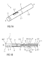
- Figure 1A is a perspective view of an exemplary embodiment of an autoinjector 1 comprising a case 2 and a cap 11 prior to use.
- Figures 1B and 1C are longitudinal sections of the autoinjector 1 prior to use.
- the autoinjector 1 comprises a case 2 including a distal case 2.1 and a proximal case 2.2 which are coupled during assembly.
- a cap 11 is removably coupled to a distal end of the case 2.
- the case 2 comprises a viewing window 2.7, which may be a hole or a transparent portion of the case 2.
- the case 2 is adapted to hold a syringe 3 containing a medicament.
- the syringe 3 may be a pre-filled syringe and have a needle 4 arranged at a distal end.
- the syringe 3 may be a medicament cartridge adapted to removably receive the needle 4 (e.g., by snap-fit, friction, threads, etc.).
- a protective needle sheath 5 may be removably attached to the needle 4.
- a stopper 6 is arranged for sealing the syringe 3 proximally and for displacing a liquid medicament M contained in the syringe 3 through the needle 4.
- a needle shroud 7 is telescoped within the case 2 and movable between an extended position and a retracted position.
- the needle shroud 7 is biased relative to the case 2 toward the extended position by a control spring 9.
- the syringe 3 may be held in a syringe carrier 8, which is slidably arranged within the case 2.
- the syringe carrier 8 may include a distal portion adapted to hold the syringe 3 and a proximal portion adapted to retain a plunger 12.
- a drive spring 10, e.g., a compression spring, may be grounded proximally on a proximal end of the syringe carrier 8 and distally on a distal end of the plunger 12.
- the plunger 12 is telescopically coupled to the proximal portion of the syringe carrier 8, and the drive spring 10 is arranged within the plunger 12 and biases the plunger 12 distally.
- the drive spring 10 is arranged within a proximal part 8.1 of the syringe carrier 8.
- a plunger 12 serves for forwarding the force of the drive spring 10 to the stopper 6.
- the plunger 12 is hollow and telescoped within the proximal part 8.1 of the syringe carrier 8 wherein the drive spring 10 is arranged within the plunger 12 biasing the plunger 12 in the distal direction D against the syringe carrier 8.
- a detent mechanism 14 is provided to initiate automated needle insertion.
- the detent mechanism 14 also locks the needle shroud 7 after autoinjector 1 has been removed from the injection site in an extended position.
- the detent mechanism 14 comprises at least one shroud boss 7.1 adapted to engage in a carrier opening 8.6 within the syringe carrier 8 for locking the needle shroud 7 to the syringe carrier 8. At least one surface of the shroud boss 7.1 and the carrier opening 8.6 may be ramped to reduce a force necessary to displace the needle shroud 7 from the extended position to the retracted position against the biasing force of the control spring 9.
- the shroud boss 7.1 abuts the carrier opening 8.6 and deflects radailly via a compliant beam 7.2 coupled to the shroud boss 7.1, disengaging the needle shroud 7 from the syringe carrier 8.
- the shroud boss 7.1 radially abuts a radial case boss 2.9, which prevents the needle shroud 7 from disengaging the syringe carrier 8 when the needle shroud 7 is in the first extended position FEP.
- An axial case boss 2.10 is adapted to distally abut the shroud boss 7.1 such that the needle shroud 7 cannot be moved distally beyond the first extended position FEP prior to use. At least one of the surfaces of the shroud boss 7.1 and the axial case boss 2.10 may be ramped such that if an axial force directed in the distal direction D is applied to the needle shroud 7 relative the case 2, the needle shroud 7 moves in the distal direction D relative the case 2 and the shroud boss 7.1 is radially inwardly deflected via the resilient beam 7.2 around the axial case boss 2.10. Prior to use, the shroud boss 7.1 is prevented from deflecting radially inward by the presence of the syringe carrier 8. Thus, prior to use the needle shroud 7.1 does not disengage the case 2.
- a plunger release mechanism 15 is arranged for preventing release of the plunger 12 prior to the needle 4 reaching an insertion depth and for releasing the plunger 12 once the needle 4 reaches its insertion depth.
- the plunger release mechanism 15 comprises: one or more compliant beams 8.3 with a respective first boss 8.4 arranged on the syringe carrier 8, a respective first opening 12.1 laterally arranged in the plunger 12 for engaging the first boss 8.4, a collar 16 slidably arranged within the case 2 and over the syringe carrier 8. When the needle shroud 7 is in the first extended position FEP, the collar 16 abuts the first boss 8.4, preventing it from disengaging the first opening 12.1.
- the collar 16 moves axially away from the first boss 8.4, so that the first boss 8.4 may deflect via the beam 8.3 and disengage from the first opening 12.1.
- the syringe carrier 8 is then disengaged from the plunger 12.
- At least surface of the first boss 8.4 and the first opening 12.1 may be ramped to reduce a force necessary to disengage the first boss 8.4 from the first opening 12.1.
- a control mechanism 21 (shown in Fig. 3B ) is arranged for selectively coupling the control spring 9 to the syringe carrier 8 or to the needle shroud 7 for advancing either in the distal direction D or opposing movement thereof in the proximal direction P.
- the collar 16 may be a component of the control mechanism 21.
- the control spring 9 is proximally grounded in the case 2 and distally bears against the collar 16 which is movable axially with respect to the case 2 and arranged over the syringe carrier 8.
- the collar 16 comprises at least one collar boss 16.1 adapted to be engaged to a step 8.5 in the carrier 8.
- At least one of the mating surfaces of the carrier boss 16.1 and the step 8.5 may be ramped to reduce a force necessary to deflect the collar boss 16.1 radially via a compliant collar beam 16.2 when it abuts the step 8.5.
- the collar boss 16.1 is prevented from deflecting radially by a narrow section 2.4 in the case 2.
- a wide section 2.5 is arranged distally from the narrow section 2.4.
- control spring 9 prior to use the control spring 9 is compressed between the case 2 and the collar 16.
- the control mechanism 21 couples the collar 16 to the syringe carrier 8 which is in turn coupled to the case 2 by the detent mechanism 14.
- a exemplary embodiment of a sequence of operation of the autoinjector 1 is as follows:
- the autoinjector 1 Prior to use, the autoinjector 1 is in the state as illustrated in figures 1 A to 1C . If applicable, the user removes the autoinjector 1 from a packaging. The medicament M may be viewed through the viewing window 2.7.
- the cap 11 is removed from the case 2 by pulling the cap 11 in the distal direction D.
- the cap 11 is coupled to the protective needle sheath 5, and thus removing the cap 11 also removes the protective needle sheath 5.
- the needle shroud 7 Prior to use, the needle shroud 7 is in the first extended position FEP protruding from the case 2 in the distal direction D.
- the first extended position FEP is defined by the detent mechanism 14, i.e. by the engagement of the shroud boss 7.1 in the carrier opening 8.6 of the syringe carrier 8 and abutment of the shroud boss 7.1 against the axial case boss 2.10 to prevent it from disengaging the carrier opening 8.6.
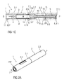
- FIGS 2A-C are perspective views of the autoinjector 1 being pressed against an injection site.
- the needle shroud 7 moves from the first extended position FEP toward a first retracted position FRP relative to the case 2. Because the needle shroud 7 is coupled to the syringe carrier 8 by the detent mechanism 14 (by the shroud boss 7.1 engagement with the carrier opening 8.6), the syringe carrier 8 (and the syringe 3 therein) are retracted relative to the case 2 such that the needle 4 is not exposed. Because the collar 16 is coupled to the syringe carrier 8 (by the collar boss 16.1 abutting the step 8.5), the collar 16 is moved with the syringe carrier 8 in the proximal direction P against the force of the control spring 9.
- the proximal end 8.1 of the syringe carrier 8 may contact (or nearly contact) a proximal end 2.11 of the case 2.
- the contact between the syringe carrier 8 and the case 2 (and/or the increased resistance provided by the control spring 9) may provide a tactile feedback that further depression of the needle shroud 7 will activate the autoinjector 1.
- the shroud boss 7.1 is proximal of the case boss 2.9 such that the shroud boss 7.1 no longer abuts the case boss 2.9.
- the biasing force of the control spring 9 is less than the force required to deflect the shroud boss 7.1 out of the carrier opening 8.6.
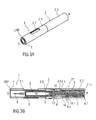
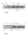
- FIGS 3A-C are perspective views of the autoinjector 1 being pressed against an injection site.
- SRP the needle shroud 7 into a second retracted position SRP
- an increase in resistance is experienced as the case 2 advances the syringe carrier 8 in the distal direction D relative to the needle shroud 7 through contact of the proximal ends 2.11, 8.1 of the case 2 and the syringe carrier 8.
- the shroud boss 7.1 is no longer radially supported by the case boss 2.9, as the case 2 is advanced in the distal direction D, the shroud boss 7.1 is deflected radially when it abuts the carrier opening 8.6, causing the syringe carrier 8 to disengage from the needle shroud 7.
- Figures 4A-C are perspective views of the autoinjector 1 being pressed against an injection site.
- the shroud boss 7.1 disengages the carrier opening 8.6, the syringe carrier 8 is decoupled from the needle shroud 7.
- the control spring 9 applies the biasing force to the collar 16, and the collar boss 16.1 pushes the step 8.5 on the syringe carrier 8 to drive the syringe carrier 8 (and the syringe 3) in the distal direction D.
- the syringe carrier 8 abuts a front stop 2.8 in the case 2, the needle 4 protrudes beyond the distal end of the case 2 and is inserted into the injection site.
- the collar 16 has been advanced in the distal direction D to such an extent, that the collar boss 16.1 is no longer supported by the narrow section 2.4 but has reached the wide section 2.5 of the case 2.
- the control spring 9 continues advancing the collar 16 and due to the syringe carrier 8 having abutted the front stop 2.8, the collar boss 16.1 is deflected radially, disengaging the collar 16 from the syringe carrier 8.
- the collar 16 advances further under the force of the control spring 9 until it abuts the needle shroud 7.
- the collar 16 advances, it is distal of the first boss 8.4 on the syringe carrier 8 so as to allow radially deflection of the first boss 8.4 due to its ramped engagement to the first opening 12.1 under load from the drive spring 10.
- the plunger 12 is thus released and advanced by the drive spring 10 displacing the stopper 6 within the syringe 3 and ejecting the medicament M through the needle 4.
- the release of the plunger release mechanism 15 may provide an audible and/or tactile feedback to the user.
- the progress of the delivery of the medicament M can be observed through the viewing window 2.7 by examining the movement of the plunger 12.
- the plunger 12 (which may be a contrasting color to the case 2) is visible in the viewing window 2.7, providing visual feedback about whether or not the autoinjector 1 has been used.
- the needle shroud 7 moves in the distal direction D, because it is abutted by the collar 16 which is driven by the control spring 9.
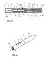
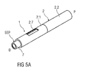
- FIGS 5A-C are perspective views of the autoinjector 1 after it is removed from the injection site.
- the shroud boss 7.1 is deflected radially by the axial case boss 2.10 since the syringe carrier 8 has been moved in the distal direction D during needle insertion and does not abut the shroud boss 7.1.
- the shroud boss 7.1 hence deflects around the case boss 2.10, and then returns to a non-deflected position when it is distal of the case boss 2.10.
- the shroud boss 7.1 abuts a ramped stop 8.7 on the syringe carrier 8 which resolves the remaining axial force of the control spring 9 and arrests the needle shroud's 7 extension.
- the needle shroud 7 is now in a second extended position SEP extending further from the case 2 than in the first extended position FEP and the extended needle 4 is hidden from view and finger access within the needle shroud 7.
- an opening may be arranged in the proximal end 2.11 of the case 2 allowing the proximal part 8.1 of the syringe carrier 8 to protrude proximally from the case 2 and serve as a trigger button (not shown).
- the detent mechanism 14 prevents release of the trigger button prior to depression of the needle shroud 7 into the retracted position RP.
- the needle shroud 7 may be fully depressed into the second retracted position SRP thereby extending the proximal part 8.1 of the syringe carrier 8 from the case 2 which may then be depressed to start an injection.
- the needle shroud 7 can re-extend into the first extended position FEP and the autoinjector 1 can return to its initial state. If the trigger button is depressed, it may be locked to the case in the depressed position to provide a visual indication that the autoinjector 1 has been used.
- the shroud boss 7.1 is no longer supported by the case boss 2.9.
- the trigger button e.g., the proximal end 8.1 of the syringe carrier 8 protruding proximally from the case 2 can now be depressed thereby radially outwardly deflecting the shroud boss 7.1 out of engagement with the carrier opening 8.6 due to their ramped engagement.
- the syringe carrier 8 is thus decoupled from the needle shroud 7 and the control spring 9, coupled to the syringe carrier 8 through the control mechanism 21, advances the syringe carrier 8 in the distal direction D extending the needle 4 from the case 2 in the distal direction D.
- the length of the syringe carrier 8 and the case 2 may be such that the proximal end 8.1 of the syringe carrier 8 is flush with the proximal end 2.11 of the case 2 once the needle 4 reaches its insertion depth.
- drug or “medicament”, as used herein, means a pharmaceutical formulation containing at least one pharmaceutically active compound, wherein in one embodiment the pharmaceutically active compound has a molecular weight up to 1500 Da and/or is a peptide, a proteine, a polysaccharide, a vaccine, a DNA, a RNA, an enzyme, an antibody or a fragment thereof, a hormone or an oligonucleotide, or a mixture of the above-mentioned pharmaceutically active compound, wherein in a further embodiment the pharmaceutically active compound is useful for the treatment and/or prophylaxis of diabetes mellitus or complications associated with diabetes mellitus such as diabetic retinopathy, thromboembolism disorders such as deep vein or pulmonary thromboembolism, acute coronary syndrome (ACS), angina, myocardial infarction, cancer, macular degeneration, inflammation, hay fever, atherosclerosis and/or rheumatoid arthritis, wherein in a further
- Insulin analogues are for example Gly(A21), Arg(B31), Arg(B32) human insulin; Lys(B3), Glu(B29) human insulin; Lys(B28), Pro(B29) human insulin; Asp(B28) human insulin; human insulin, wherein proline in position B28 is replaced by Asp, Lys, Leu, Val or Ala and wherein in position B29 Lys may be replaced by Pro; Ala(B26) human insulin; Des(B28-B30) human insulin; Des(B27) human insulin and Des(B30) human insulin.
- Insulin derivates are for example B29-N-myristoyl-des(B30) human insulin; B29-N-palmitoyl-des(B30) human insulin; B29-N-myristoyl human insulin; B29-N-palmitoyl human insulin; B28-N-myristoyl LysB28ProB29 human insulin; B28-N-palmitoyl-LysB28ProB29 human insulin; B30-N-myristoyl-ThrB29LysB30 human insulin; B30-N-palmitoyl- ThrB29LysB30 human insulin; B29-N-(N-palmitoyl-Y-glutamyl)-des(B30) human insulin; B29-N-(N-lithocholyl-Y-glutamyl)-des(B30) human insulin; B29-N-( ⁇ -carboxyheptadecanoyl)-des(B30) human insulin and B29-N-( ⁇ -carbox
- Exendin-4 for example means Exendin-4(1-39), a peptide of the sequence H-His-Gly-Glu-Gly-Thr-Phe-Thr-Ser-Asp-Leu-Ser-Lys-Gln-Met-Glu-Glu-Glu-Ala-Val-Arg-Leu-Phe-Ile-Glu-Trp-Leu-Lys-Asn-Gly-Gly-Pro-Ser-Ser-Gly-Ala-Pro-Pro-Pro-Ser-NH2.
- Exendin-4 derivatives are for example selected from the following list of compounds:
- Hormones are for example hypophysis hormones or hypothalamus hormones or regulatory active peptides and their antagonists as listed in Rote Liste, ed. 2008, Chapter 50, such as Gonadotropine (Follitropin, Lutropin, Choriongonadotropin, Menotropin), Somatropine (Somatropin), Desmopressin, Terlipressin, Gonadorelin, Triptorelin, Leuprorelin, Buserelin, Nafarelin, Goserelin.
- Gonadotropine Follitropin, Lutropin, Choriongonadotropin, Menotropin
- Somatropine Somatropin
- Desmopressin Terlipressin
- Gonadorelin Triptorelin
- Leuprorelin Buserelin
- Nafarelin Goserelin.
- a polysaccharide is for example a glucosaminoglycane, a hyaluronic acid, a heparin, a low molecular weight heparin or an ultra low molecular weight heparin or a derivative thereof, or a sulphated, e.g. a poly-sulphated form of the above-mentioned polysaccharides, and/or a pharmaceutically acceptable salt thereof.
- An example of a pharmaceutically acceptable salt of a poly-sulphated low molecular weight heparin is enoxaparin sodium.
- Antibodies are globular plasma proteins ( ⁇ 150 kDa) that are also known as immunoglobulins which share a basic structure. As they have sugar chains added to amino acid residues, they are glycoproteins.
- the basic functional unit of each antibody is an immunoglobulin (Ig) monomer (containing only one Ig unit); secreted antibodies can also be dimeric with two Ig units as with IgA, tetrameric with four Ig units like teleost fish IgM, or pentameric with five Ig units, like mammalian IgM.
- Ig immunoglobulin
- the Ig monomer is a "Y"-shaped molecule that consists of four polypeptide chains; two identical heavy chains and two identical light chains connected by disulfide bonds between cysteine residues. Each heavy chain is about 440 amino acids long; each light chain is about 220 amino acids long. Heavy and light chains each contain intrachain disulfide bonds which stabilize their folding. Each chain is composed of structural domains called Ig domains. These domains contain about 70-110 amino acids and are classified into different categories (for example, variable or V, and constant or C) according to their size and function. They have a characteristic immunoglobulin fold in which two ⁇ sheets create a "sandwich" shape, held together by interactions between conserved cysteines and other charged amino acids.
- Ig heavy chain There are five types of mammalian Ig heavy chain denoted by ⁇ , ⁇ , ⁇ , ⁇ , and ⁇ .
- the type of heavy chain present defines the isotype of antibody; these chains are found in IgA, IgD, IgE, IgG, and IgM antibodies, respectively.
- Distinct heavy chains differ in size and composition; ⁇ and ⁇ contain approximately 450 amino acids and ⁇ approximately 500 amino acids, while ⁇ and ⁇ have approximately 550 amino acids.
- Each heavy chain has two regions, the constant region (C H ) and the variable region (V H ).
- the constant region is essentially identical in all antibodies of the same isotype, but differs in antibodies of different isotypes.
- Heavy chains ⁇ , ⁇ and ⁇ have a constant region composed of three tandem Ig domains, and a hinge region for added flexibility; heavy chains ⁇ and ⁇ have a constant region composed of four immunoglobulin domains.
- the variable region of the heavy chain differs in antibodies produced by different B cells, but is the same for all antibodies produced by a single B cell or B cell clone.
- the variable region of each heavy chain is approximately 110 amino acids long and is composed of a single Ig domain.
- a light chain has two successive domains: one constant domain (CL) and one variable domain (VL).
- CL constant domain
- VL variable domain
- the approximate length of a light chain is 211 to 217 amino acids.
- Each antibody contains two light chains that are always identical; only one type of light chain, k or ⁇ , is present per antibody in mammals.
- variable (V) regions are responsible for binding to the antigen, i.e. for its antigen specificity.
- VL variable light
- VH variable heavy chain
- CDRs Complementarity Determining Regions
- an "antibody fragment” contains at least one antigen binding fragment as defined above, and exhibits essentially the same function and specificity as the complete antibody of which the fragment is derived from.
- Limited proteolytic digestion with papain cleaves the Ig prototype into three fragments. Two identical amino terminal fragments, each containing one entire L chain and about half an H chain, are the antigen binding fragments (Fab).
- the Fc contains carbohydrates, complement-binding, and FcR-binding sites.
- F(ab')2 is divalent for antigen binding.
- the disulfide bond of F(ab')2 may be cleaved in order to obtain Fab'.
- the variable regions of the heavy and light chains can be fused together to form a single chain variable fragment (scFv).
- Pharmaceutically acceptable salts are for example acid addition salts and basic salts.
- Acid addition salts are e.g. HCl or HBr salts.
- Basic salts are e.g. salts having a cation selected from alkali or alkaline, e.g. Na+, or K+, or Ca2+, or an ammonium ion N+(R1)(R2)(R3)(R4), wherein R1 to R4 independently of each other mean: hydrogen, an optionally substituted C1-C6-alkyl group, an optionally substituted C2-C6-alkenyl group, an optionally substituted C6-C10-aryl group, or an optionally substituted C6-C10-heteroaryl group.
- solvates are for example hydrates.
Landscapes
- Health & Medical Sciences (AREA)
- Engineering & Computer Science (AREA)
- Heart & Thoracic Surgery (AREA)
- Vascular Medicine (AREA)
- Anesthesiology (AREA)
- Biomedical Technology (AREA)
- Hematology (AREA)
- Life Sciences & Earth Sciences (AREA)
- Animal Behavior & Ethology (AREA)
- General Health & Medical Sciences (AREA)
- Public Health (AREA)
- Veterinary Medicine (AREA)
- Environmental & Geological Engineering (AREA)
- Infusion, Injection, And Reservoir Apparatuses (AREA)
Abstract
Described is an autoinjector (1) comprising a case (2), a syringe carrier (8) slidably disposed within the case (2) and adapted to hold a syringe (3) including a stopper (6), a plunger (12) slidably disposed within the syringe carrier (8) and adapted to apply a force on the stopper (6), and a drive spring (10) disposed within the plunger (12) and biasing the plunger (12) relative to the syringe carrier (8).
Description
- The invention relates to an autoinjector.
- Administering an injection is a process which presents a number of risks and challenges for users and healthcare professionals, both mental and physical. Injection devices typically fall into two categories - manual devices and autoinjectors. In a conventional manual device, manual force is required to drive a medicament through a needle. This is typically done by some form of button / plunger that has to be continuously pressed during the injection. There are numerous disadvantages associated with this approach. For example, if the button / plunger is released prematurely, the injection will stop and may not deliver an intended dose. Further, the force required to push the button / plunger may be too high (e.g., if the user is elderly or a child). And, aligning the injection device, administering the injection and keeping the injection device still during the injection may require dexterity which some patients (e.g., elderly patients, children, arthritic patients, etc.) may not have.
- Autoinjector devices aim to make self-injection easier for patients. A conventional autoinjector may provide the force for administering the injection by a spring, and trigger button or other mechanism may be used to activate the injection. Autoinjectors may be single-use or reusable devices.
- There remains a need for an improved autoinjector.
- It is an object of the present invention to provide an improved autoinjector.
- In an exemplary embodiment, an autoinjector according to the present invention comprises a case, a syringe carrier slidably disposed within the case and adapted to hold a syringe including a stopper, a plunger slidably disposed within the syringe carrier and adapted to apply a force on the stopper, and a drive spring disposed within the plunger and biasing the plunger relative to the syringe carrier.
- In an exemplary embodiment, the autoinjector further comprises a needle shroud slidably disposed within the case. The needle shroud is telescopically arranged over the syringe carrier. In an exemplary embodiment, the autoinjector further comprises detent mechanism adapted to couple the needle shroud to the syringe carrier and adapted to couple the needle shroud to the case. The detent mechanism comprises a resilient shroud beam on the needle shroud having a shroud boss releasably engaging a carrier opening in the syringe carrier. The case includes a proximal case boss abutting the shroud boss when the needle shroud is in a first extended position.
- In an exemplary embodiment, the autoinjector further comprises a plunger release mechanism adapted to releasably couple the plunger to the syringe carrier. The plunger release mechanism comprises a resilient carrier beam on the syringe carrier having a carrier boss releasably engaging a plunger opening in the plunger.
- In an exemplary embodiment, the autoinjector further comprises a collar slidably arranged on the syringe carrier, and a control spring applying a biasing force to the collar. The collar includes a resilient collar beam having a collar boss adapted to releasably engage a step on the syringe carrier. The collar abuts the carrier boss when the needle shroud is in the first extended position. The collar, the needle shroud and the syringe carrier are moved proximally relative to the case when the needle shroud is moved from the first extended position to a first retracted position. A proximal end of the syringe carrier abuts a proximal end of the case when the needle shroud is in the first retracted position to provide a feedback. The shroud boss is proximal of the proximal case boss when the needle shroud is in the first retracted position. The syringe carrier is advanced distally when the needle shroud is in a second retracted position proximal of the first retracted position, and the shroud boss disengages the carrier opening. When the shroud boss disengages the carrier opening, the collar pushes the syringe carrier distally until the syringe carrier abuts a front stop in the case and the collar disengages the syringe carrier under the biasing force of the control spring and pushes the needle shroud into a second extended position relative to the case. When the collar disengages the syringe carrier, the carrier boss disengages the plunger opening to release the plunger. The shroud boss abuts a distal case boss when the needle shroud is in the second extended position.
- In an exemplary embodiment, the syringe carrier with the integrated drive spring allows for employing a strong drive spring without any impact on the user when triggering the autoinjector or during needle insertion since these actions are achieved or opposed by the control spring which can be specified considerably weaker than the drive spring. This allows for delivering highly viscous medicaments.
- In an exemplary embodiment, releasing the drive spring upon the needle reaching an insertion depth avoids a so called wet injection, i.e. medicament leaking out of the needle which is a problem in conventional art autoinjectors, where both needle insertion and injection are achieved by pushing on the stopper.
- In an exemplary embodiment, the autoinjector has a particularly low part count compared to most conventional autoinjectors thus reducing manufacturing costs. The arrangement with separate control spring for advancing the syringe and the needle shroud and a drive spring for fluid injection allows for using one design for different viscosity liquids by just changing the drive spring, and for different volumes just by changing the length of the plunger. This may be an advantage over conventional designs where the drive spring also serves for needle insertion and/or for advancing a shroud.
- Further scope of applicability of the present invention will become apparent from the detailed description given hereinafter. However, it should be understood that the detailed description and specific examples, while indicating preferred embodiments of the invention, are given by way of illustration only, since various changes and modifications within the spirit and scope of the invention will become apparent to those skilled in the art from this detailed description.
- The present invention will become more fully understood from the detailed description given hereinbelow and the accompanying drawings which are given by way of illustration only, and thus, are not limitive of the present invention, and wherein:
- Figure 1A
- is a perspective view of an exemplary embodiment of an autoinjector according to the present invention prior to use,
- Figure 1B
- is a longitudinal section of an exemplary embodiment of an autoinjector according to the present invention prior to use,
- Figure 1C
- is a different longitudinal section of an exemplary embodiment of an autoinjector according to the present invention prior to use,
- Figure 2A
- is a perspective view of an exemplary embodiment of an autoinjector according to the present invention during use,
- Figure 2B
- is a longitudinal section of an exemplary embodiment of an autoinjector according to the present invention during use,
- Figure 2C
- is a different longitudinal section of an exemplary embodiment of an autoinjector according to the present invention during use,
- Figure 3A
- is a perspective view of an exemplary embodiment of an autoinjector according to the present invention during use,
- Figure 3B
- is a longitudinal section of an exemplary embodiment of an autoinjector according to the present invention during use,
- Figure 3C
- is a different longitudinal section of an exemplary embodiment of an autoinjector according to the present invention during use,
- Figure 4A
- is a perspective view of an exemplary embodiment of an autoinjector according to the present invention during use,
- Figure 4B
- is a longitudinal section of an exemplary embodiment of an autoinjector according to the present invention during use,
- Figure 4C
- is a different longitudinal section of an exemplary embodiment of an autoinjector according to the present invention during use,
- Figure 5A
- is a perspective view of an exemplary embodiment of an autoinjector according to the present invention after use,
- Figure 5B
- is a longitudinal section of an exemplary embodiment of an autoinjector according to the present invention after use, and
- Figure 5C
- is a different longitudinal section of an exemplary embodiment of an autoinjector according to the present invention after use.
- Corresponding parts are marked with the same reference symbols in all figures.
-
Figure 1A is a perspective view of an exemplary embodiment of anautoinjector 1 comprising acase 2 and acap 11 prior to use.Figures 1B and1C are longitudinal sections of theautoinjector 1 prior to use. - In an exemplary embodiment, the
autoinjector 1 comprises acase 2 including a distal case 2.1 and a proximal case 2.2 which are coupled during assembly. Acap 11 is removably coupled to a distal end of thecase 2. Thecase 2 comprises a viewing window 2.7, which may be a hole or a transparent portion of thecase 2. - The
case 2 is adapted to hold asyringe 3 containing a medicament. Thesyringe 3 may be a pre-filled syringe and have aneedle 4 arranged at a distal end. In another exemplary embodiment, thesyringe 3 may be a medicament cartridge adapted to removably receive the needle 4 (e.g., by snap-fit, friction, threads, etc.). Aprotective needle sheath 5 may be removably attached to theneedle 4. Astopper 6 is arranged for sealing thesyringe 3 proximally and for displacing a liquid medicament M contained in thesyringe 3 through theneedle 4. - A
needle shroud 7 is telescoped within thecase 2 and movable between an extended position and a retracted position. Theneedle shroud 7 is biased relative to thecase 2 toward the extended position by acontrol spring 9. - In an exemplary embodiment, the
syringe 3 may be held in asyringe carrier 8, which is slidably arranged within thecase 2. Thesyringe carrier 8 may include a distal portion adapted to hold thesyringe 3 and a proximal portion adapted to retain aplunger 12. Adrive spring 10, e.g., a compression spring, may be grounded proximally on a proximal end of thesyringe carrier 8 and distally on a distal end of theplunger 12. In an exemplary embodiment, theplunger 12 is telescopically coupled to the proximal portion of thesyringe carrier 8, and thedrive spring 10 is arranged within theplunger 12 and biases theplunger 12 distally. - In an exemplary embodiment, the
drive spring 10 is arranged within a proximal part 8.1 of thesyringe carrier 8. Aplunger 12 serves for forwarding the force of thedrive spring 10 to thestopper 6. In an exemplary embodiment theplunger 12 is hollow and telescoped within the proximal part 8.1 of thesyringe carrier 8 wherein thedrive spring 10 is arranged within theplunger 12 biasing theplunger 12 in the distal direction D against thesyringe carrier 8. - In an exemplary embodiment, a
detent mechanism 14 is provided to initiate automated needle insertion. Thedetent mechanism 14 also locks theneedle shroud 7 afterautoinjector 1 has been removed from the injection site in an extended position. - In an exemplary embodiment, the
detent mechanism 14 comprises at least one shroud boss 7.1 adapted to engage in a carrier opening 8.6 within thesyringe carrier 8 for locking theneedle shroud 7 to thesyringe carrier 8. At least one surface of the shroud boss 7.1 and the carrier opening 8.6 may be ramped to reduce a force necessary to displace theneedle shroud 7 from the extended position to the retracted position against the biasing force of thecontrol spring 9. When the force on theneedle shroud 7 overcomes the biasing force of thecontrol spring 9, the shroud boss 7.1 abuts the carrier opening 8.6 and deflects radailly via a compliant beam 7.2 coupled to the shroud boss 7.1, disengaging theneedle shroud 7 from thesyringe carrier 8. When theneedle shroud 7 is in a first extended position FEP relative to the case 2 (as shown inFigs. 1B and1 C ), the shroud boss 7.1 radially abuts a radial case boss 2.9, which prevents theneedle shroud 7 from disengaging thesyringe carrier 8 when theneedle shroud 7 is in the first extended position FEP. An axial case boss 2.10 is adapted to distally abut the shroud boss 7.1 such that theneedle shroud 7 cannot be moved distally beyond the first extended position FEP prior to use. At least one of the surfaces of the shroud boss 7.1 and the axial case boss 2.10 may be ramped such that if an axial force directed in the distal direction D is applied to theneedle shroud 7 relative thecase 2, theneedle shroud 7 moves in the distal direction D relative thecase 2 and the shroud boss 7.1 is radially inwardly deflected via the resilient beam 7.2 around the axial case boss 2.10. Prior to use, the shroud boss 7.1 is prevented from deflecting radially inward by the presence of thesyringe carrier 8. Thus, prior to use the needle shroud 7.1 does not disengage thecase 2. - In an exemplary embodiment, a
plunger release mechanism 15 is arranged for preventing release of theplunger 12 prior to theneedle 4 reaching an insertion depth and for releasing theplunger 12 once theneedle 4 reaches its insertion depth. In an exemplary embodiment, theplunger release mechanism 15 comprises: one or more compliant beams 8.3 with a respective first boss 8.4 arranged on thesyringe carrier 8, a respective first opening 12.1 laterally arranged in theplunger 12 for engaging the first boss 8.4, acollar 16 slidably arranged within thecase 2 and over thesyringe carrier 8. When theneedle shroud 7 is in the first extended position FEP, thecollar 16 abuts the first boss 8.4, preventing it from disengaging the first opening 12.1. As described further below, as theneedle 4 reaches its insertion depth, thecollar 16 moves axially away from the first boss 8.4, so that the first boss 8.4 may deflect via the beam 8.3 and disengage from the first opening 12.1. Thesyringe carrier 8 is then disengaged from theplunger 12. At least surface of the first boss 8.4 and the first opening 12.1 may be ramped to reduce a force necessary to disengage the first boss 8.4 from the first opening 12.1. - In an exemplary embodiment, a control mechanism 21 (shown in
Fig. 3B ) is arranged for selectively coupling thecontrol spring 9 to thesyringe carrier 8 or to theneedle shroud 7 for advancing either in the distal direction D or opposing movement thereof in the proximal direction P. In an exemplary embodiment, thecollar 16 may be a component of thecontrol mechanism 21. Thecontrol spring 9 is proximally grounded in thecase 2 and distally bears against thecollar 16 which is movable axially with respect to thecase 2 and arranged over thesyringe carrier 8. Thecollar 16 comprises at least one collar boss 16.1 adapted to be engaged to a step 8.5 in thecarrier 8. At least one of the mating surfaces of the carrier boss 16.1 and the step 8.5 may be ramped to reduce a force necessary to deflect the collar boss 16.1 radially via a compliant collar beam 16.2 when it abuts the step 8.5. Once assembled, the collar boss 16.1 is prevented from deflecting radially by a narrow section 2.4 in thecase 2. A wide section 2.5 is arranged distally from the narrow section 2.4. Upon axial movement of thesyringe carrier 8 and thecollar 16 in the distal direction D, the carrier boss 16.1 can deflect radially when thecollar 16 enters the wide section 2.5 and disengage thecollar 16 from thesyringe carrier 8 under force from thecontrol spring 9. - In an exemplary embodiment, prior to use the
control spring 9 is compressed between thecase 2 and thecollar 16. Thecontrol mechanism 21 couples thecollar 16 to thesyringe carrier 8 which is in turn coupled to thecase 2 by thedetent mechanism 14. - A exemplary embodiment of a sequence of operation of the
autoinjector 1 is as follows: - Prior to use, the
autoinjector 1 is in the state as illustrated infigures 1 A to 1C . If applicable, the user removes theautoinjector 1 from a packaging. The medicament M may be viewed through the viewing window 2.7. Thecap 11 is removed from thecase 2 by pulling thecap 11 in the distal direction D. Thecap 11 is coupled to theprotective needle sheath 5, and thus removing thecap 11 also removes theprotective needle sheath 5. Prior to use, theneedle shroud 7 is in the first extended position FEP protruding from thecase 2 in the distal direction D. The first extended position FEP is defined by thedetent mechanism 14, i.e. by the engagement of the shroud boss 7.1 in the carrier opening 8.6 of thesyringe carrier 8 and abutment of the shroud boss 7.1 against the axial case boss 2.10 to prevent it from disengaging the carrier opening 8.6. -
Figures 2A-C are perspective views of theautoinjector 1 being pressed against an injection site. When theautoinjector 1 is pressed against the injection site, theneedle shroud 7 moves from the first extended position FEP toward a first retracted position FRP relative to thecase 2. Because theneedle shroud 7 is coupled to thesyringe carrier 8 by the detent mechanism 14 (by the shroud boss 7.1 engagement with the carrier opening 8.6), the syringe carrier 8 (and thesyringe 3 therein) are retracted relative to thecase 2 such that theneedle 4 is not exposed. Because thecollar 16 is coupled to the syringe carrier 8 (by the collar boss 16.1 abutting the step 8.5), thecollar 16 is moved with thesyringe carrier 8 in the proximal direction P against the force of thecontrol spring 9. - When the
needle shroud 7 has reached the first retracted position FRP, the proximal end 8.1 of thesyringe carrier 8 may contact (or nearly contact) a proximal end 2.11 of thecase 2. The contact between thesyringe carrier 8 and the case 2 (and/or the increased resistance provided by the control spring 9) may provide a tactile feedback that further depression of theneedle shroud 7 will activate theautoinjector 1. In the first retracted position FRP, the shroud boss 7.1 is proximal of the case boss 2.9 such that the shroud boss 7.1 no longer abuts the case boss 2.9. However, in an exemplary embodiment, the biasing force of thecontrol spring 9 is less than the force required to deflect the shroud boss 7.1 out of the carrier opening 8.6. Thus, if theneedle shroud 7 is not further depressed and theautoinjector 1 is removed from the injection site (or axial force is no longer applied to the autoinjector 1), theneedle shroud 7 will re-extend into the first extended position FEP and theautoinjector 1 will return to its initial state. -
Figures 3A-C are perspective views of theautoinjector 1 being pressed against an injection site. As the user continues to depress theneedle shroud 7 into a second retracted position SRP, an increase in resistance is experienced as thecase 2 advances thesyringe carrier 8 in the distal direction D relative to theneedle shroud 7 through contact of the proximal ends 2.11, 8.1 of thecase 2 and thesyringe carrier 8. As the shroud boss 7.1 is no longer radially supported by the case boss 2.9, as thecase 2 is advanced in the distal direction D, the shroud boss 7.1 is deflected radially when it abuts the carrier opening 8.6, causing thesyringe carrier 8 to disengage from theneedle shroud 7. -
Figures 4A-C are perspective views of theautoinjector 1 being pressed against an injection site. When the shroud boss 7.1 disengages the carrier opening 8.6, thesyringe carrier 8 is decoupled from theneedle shroud 7. Thecontrol spring 9 applies the biasing force to thecollar 16, and the collar boss 16.1 pushes the step 8.5 on thesyringe carrier 8 to drive the syringe carrier 8 (and the syringe 3) in the distal direction D. When thesyringe carrier 8 abuts a front stop 2.8 in thecase 2, theneedle 4 protrudes beyond the distal end of thecase 2 and is inserted into the injection site. Thecollar 16 has been advanced in the distal direction D to such an extent, that the collar boss 16.1 is no longer supported by the narrow section 2.4 but has reached the wide section 2.5 of thecase 2. Thecontrol spring 9 continues advancing thecollar 16 and due to thesyringe carrier 8 having abutted the front stop 2.8, the collar boss 16.1 is deflected radially, disengaging thecollar 16 from thesyringe carrier 8. Thecollar 16 advances further under the force of thecontrol spring 9 until it abuts theneedle shroud 7. - As the
collar 16 advances, it is distal of the first boss 8.4 on thesyringe carrier 8 so as to allow radially deflection of the first boss 8.4 due to its ramped engagement to the first opening 12.1 under load from thedrive spring 10. Theplunger 12 is thus released and advanced by thedrive spring 10 displacing thestopper 6 within thesyringe 3 and ejecting the medicament M through theneedle 4. The release of theplunger release mechanism 15 may provide an audible and/or tactile feedback to the user. The progress of the delivery of the medicament M can be observed through the viewing window 2.7 by examining the movement of theplunger 12. The plunger 12 (which may be a contrasting color to the case 2) is visible in the viewing window 2.7, providing visual feedback about whether or not theautoinjector 1 has been used. - If the user removes the
autoinjector 1 from the injection site at any time after theneedle 4 having reached insertion depth, theneedle shroud 7 moves in the distal direction D, because it is abutted by thecollar 16 which is driven by thecontrol spring 9. -
Figures 5A-C are perspective views of theautoinjector 1 after it is removed from the injection site. As theneedle shroud 7 advances in the distal direction D under the force of thecontrol spring 9, the shroud boss 7.1 is deflected radially by the axial case boss 2.10 since thesyringe carrier 8 has been moved in the distal direction D during needle insertion and does not abut the shroud boss 7.1. The shroud boss 7.1 hence deflects around the case boss 2.10, and then returns to a non-deflected position when it is distal of the case boss 2.10. The shroud boss 7.1 abuts a ramped stop 8.7 on thesyringe carrier 8 which resolves the remaining axial force of thecontrol spring 9 and arrests the needle shroud's 7 extension. Theneedle shroud 7 is now in a second extended position SEP extending further from thecase 2 than in the first extended position FEP and theextended needle 4 is hidden from view and finger access within theneedle shroud 7. - Any attempt to displace the
needle shroud 7 in the proximal direction P relative to thecase 2 from the second extended position SEP is prevented, because the shroud boss 7.1 abuts a distal end of the case boss 2.10. - In another exemplary embodiment, an opening may be arranged in the proximal end 2.11 of the
case 2 allowing the proximal part 8.1 of thesyringe carrier 8 to protrude proximally from thecase 2 and serve as a trigger button (not shown). In this exemplary embodiment, thedetent mechanism 14 prevents release of the trigger button prior to depression of theneedle shroud 7 into the retracted position RP. Theneedle shroud 7 may be fully depressed into the second retracted position SRP thereby extending the proximal part 8.1 of thesyringe carrier 8 from thecase 2 which may then be depressed to start an injection. If the trigger button is not depressed at this point, theneedle shroud 7 can re-extend into the first extended position FEP and theautoinjector 1 can return to its initial state. If the trigger button is depressed, it may be locked to the case in the depressed position to provide a visual indication that theautoinjector 1 has been used. - After full depression of the
needle shroud 7 into the second retracted position SRP, the shroud boss 7.1 is no longer supported by the case boss 2.9. The trigger button, e.g., the proximal end 8.1 of thesyringe carrier 8 protruding proximally from thecase 2 can now be depressed thereby radially outwardly deflecting the shroud boss 7.1 out of engagement with the carrier opening 8.6 due to their ramped engagement. Thesyringe carrier 8 is thus decoupled from theneedle shroud 7 and thecontrol spring 9, coupled to thesyringe carrier 8 through thecontrol mechanism 21, advances thesyringe carrier 8 in the distal direction D extending theneedle 4 from thecase 2 in the distal direction D. The length of thesyringe carrier 8 and thecase 2 may be such that the proximal end 8.1 of thesyringe carrier 8 is flush with the proximal end 2.11 of thecase 2 once theneedle 4 reaches its insertion depth. - The term "drug" or "medicament", as used herein, means a pharmaceutical formulation containing at least one pharmaceutically active compound,
wherein in one embodiment the pharmaceutically active compound has a molecular weight up to 1500 Da and/or is a peptide, a proteine, a polysaccharide, a vaccine, a DNA, a RNA, an enzyme, an antibody or a fragment thereof, a hormone or an oligonucleotide, or a mixture of the above-mentioned pharmaceutically active compound,
wherein in a further embodiment the pharmaceutically active compound is useful for the treatment and/or prophylaxis of diabetes mellitus or complications associated with diabetes mellitus such as diabetic retinopathy, thromboembolism disorders such as deep vein or pulmonary thromboembolism, acute coronary syndrome (ACS), angina, myocardial infarction, cancer, macular degeneration, inflammation, hay fever, atherosclerosis and/or rheumatoid arthritis,
wherein in a further embodiment the pharmaceutically active compound comprises at least one peptide for the treatment and/or prophylaxis of diabetes mellitus or complications associated with diabetes mellitus such as diabetic retinopathy,
wherein in a further embodiment the pharmaceutically active compound comprises at least one human insulin or a human insulin analogue or derivative, glucagon-like peptide (GLP-1) or an analogue or derivative thereof, or exendin-3 or exendin-4 or an analogue or derivative of exendin-3 or exendin-4. - Insulin analogues are for example Gly(A21), Arg(B31), Arg(B32) human insulin; Lys(B3), Glu(B29) human insulin; Lys(B28), Pro(B29) human insulin; Asp(B28) human insulin; human insulin, wherein proline in position B28 is replaced by Asp, Lys, Leu, Val or Ala and wherein in position B29 Lys may be replaced by Pro; Ala(B26) human insulin; Des(B28-B30) human insulin; Des(B27) human insulin and Des(B30) human insulin.
- Insulin derivates are for example B29-N-myristoyl-des(B30) human insulin; B29-N-palmitoyl-des(B30) human insulin; B29-N-myristoyl human insulin; B29-N-palmitoyl human insulin; B28-N-myristoyl LysB28ProB29 human insulin; B28-N-palmitoyl-LysB28ProB29 human insulin; B30-N-myristoyl-ThrB29LysB30 human insulin; B30-N-palmitoyl- ThrB29LysB30 human insulin; B29-N-(N-palmitoyl-Y-glutamyl)-des(B30) human insulin; B29-N-(N-lithocholyl-Y-glutamyl)-des(B30) human insulin; B29-N-(ω-carboxyheptadecanoyl)-des(B30) human insulin and B29-N-(ω-carboxyheptadecanoyl) human insulin.
- Exendin-4 for example means Exendin-4(1-39), a peptide of the sequence H-His-Gly-Glu-Gly-Thr-Phe-Thr-Ser-Asp-Leu-Ser-Lys-Gln-Met-Glu-Glu-Glu-Ala-Val-Arg-Leu-Phe-Ile-Glu-Trp-Leu-Lys-Asn-Gly-Gly-Pro-Ser-Ser-Gly-Ala-Pro-Pro-Pro-Ser-NH2.
- Exendin-4 derivatives are for example selected from the following list of compounds:
- H-(Lys)4-des Pro36, des Pro37 Exendin-4(1-39)-NH2,
H-(Lys)5-des Pro36, des Pro37 Exendin-4(1-39)-NH2,
des Pro36 Exendin-4(1-39),
des Pro36 [Asp28] Exendin-4(1-39),
des Pro36 [IsoAsp28] Exendin-4(1-39),
des Pro36 [Met(O)14, Asp28] Exendin-4(1-39),
des Pro36 [Met(O)14, IsoAsp28] Exendin-4(1-39),
des Pro36 [Trp(02)25, Asp28] Exendin-4(1-39),
des Pro36 [Trp(02)25, IsoAsp28] Exendin-4(1-39),
des Pro36 [Met(O)14 Trp(02)25, Asp28] Exendin-4(1-39),
des Pro36 [Met(O)14 Trp(02)25, IsoAsp28] Exendin-4(1-39); or - des Pro36 [Asp28] Exendin-4(1-39),
des Pro36 [IsoAsp28] Exendin-4(1-39),
des Pro36 [Met(O)14, Asp28] Exendin-4(1-39),
des Pro36 [Met(O)14, IsoAsp28] Exendin-4(1-39),
des Pro36 [Trp(02)25, Asp28] Exendin-4(1-39),
des Pro36 [Trp(02)25, IsoAsp28] Exendin-4(1-39),
des Pro36 [Met(O)14 Trp(02)25, Asp28] Exendin-4(1-39),
des Pro36 [Met(O)14 Trp(02)25, IsoAsp28] Exendin-4(1-39),
wherein the group -Lys6-NH2 may be bound to the C-terminus of the Exendin-4 derivative; - or an Exendin-4 derivative of the sequence
des Pro36 Exendin-4(1-39)-Lys6-NH2 (AVE0010),
H-(Lys)6-des Pro36 [Asp28] Exendin-4(1-39)-Lys6-NH2,
des Asp28 Pro36, Pro37, Pro38Exendin-4(1-39)-NH2,
H-(Lys)6-des Pro36, Pro38 [Asp28] Exendin-4(1-39)-NH2,
H-Asn-(Glu)5des Pro36, Pro37, Pro38 [Asp28] Exendin-4(1-39)-NH2,
des Pro36, Pro37, Pro38 [Asp28] Exendin-4(1-39)-(Lys)6-NH2,
H-(Lys)6-des Pro36, Pro37, Pro38 [Asp28] Exendin-4(1-39)-(Lys)6-NH2,
H-Asn-(Glu)5-des Pro36, Pro37, Pro38 [Asp28] Exendin-4(1-39)-(Lys)6-NH2,
H-(Lys)6-des Pro36 [Trp(02)25, Asp28] Exendin-4(1-39)-Lys6-NH2,
H-des Asp28 Pro36, Pro37, Pro38 [Trp(02)25] Exendin-4(1-39)-NH2,
H-(Lys)6-des Pro36, Pro37, Pro38 [Trp(02)25, Asp28] Exendin-4(1-39)-NH2,
H-Asn-(Glu)5-des Pro36, Pro37, Pro38 [Trp(02)25, Asp28] Exendin-4(1-39)-NH2,
des Pro36, Pro37, Pro38 [Trp(02)25, Asp28] Exendin-4(1-39)-(Lys)6-NH2,
H-(Lys)6-des Pro36, Pro37, Pro38 [Trp(02)25, Asp28] Exendin-4(1-39)-(Lys)6-NH2,
H-Asn-(Glu)5-des Pro36, Pro37, Pro38 [Trp(02)25, Asp28] Exendin-4(1-39)-(Lys)6-NH2,
H-(Lys)6-des Pro36 [Met(O)14, Asp28] Exendin-4(1-39)-Lys6-NH2,
des Met(O)14 Asp28 Pro36, Pro37, Pro38 Exendin-4(1-39)-NH2,
H-(Lys)6-desPro36, Pro37, Pro38 [Met(O)14, Asp28] Exendin-4(1-39)-NH2,
H-Asn-(Glu)5-des Pro36, Pro37, Pro38 [Met(O)14, Asp28] Exendin-4(1-39)-NH2,
des Pro36, Pro37, Pro38 [Met(O)14, Asp28] Exendin-4(1-39)-(Lys)6-NH2,
H-(Lys)6-des Pro36, Pro37, Pro38 [Met(O)14, Asp28] Exendin-4(1-39)-(Lys)6-NH2,
H-Asn-(Glu)5 des Pro36, Pro37, Pro38 [Met(O)14, Asp28] Exendin-4(1-39)-(Lys)6-NH2,
H-Lys6-des Pro36 [Met(O)14, Trp(02)25, Asp28] Exendin-4(1-39)-Lys6-NH2,
H-des Asp28 Pro36, Pro37, Pro38 [Met(O)14, Trp(02)25] Exendin-4(1-39)-NH2,
H-(Lys)6-des Pro36, Pro37, Pro38 [Met(O)14, Asp28] Exendin-4(1-39)-NH2,
H-Asn-(Glu)5-des Pro36, Pro37, Pro38 [Met(O)14, Trp(02)25, Asp28] Exendin-4(1-39)-NH2,
des Pro36, Pro37, Pro38 [Met(O)14, Trp(02)25, Asp28] Exendin-4(1-39)-(Lys)6-NH2,
H-(Lys)6-des Pro36, Pro37, Pro38 [Met(O)14, Trp(02)25, Asp28] Exendin-4(S1-39)-(Lys)6-NH2,
H-Asn-(Glu)5-des Pro36, Pro37, Pro38 [Met(O)14, Trp(02)25, Asp28] Exendin-4(1-39)-(Lys)6-NH2; - Hormones are for example hypophysis hormones or hypothalamus hormones or regulatory active peptides and their antagonists as listed in Rote Liste, ed. 2008, Chapter 50, such as Gonadotropine (Follitropin, Lutropin, Choriongonadotropin, Menotropin), Somatropine (Somatropin), Desmopressin, Terlipressin, Gonadorelin, Triptorelin, Leuprorelin, Buserelin, Nafarelin, Goserelin.
- A polysaccharide is for example a glucosaminoglycane, a hyaluronic acid, a heparin, a low molecular weight heparin or an ultra low molecular weight heparin or a derivative thereof, or a sulphated, e.g. a poly-sulphated form of the above-mentioned polysaccharides, and/or a pharmaceutically acceptable salt thereof. An example of a pharmaceutically acceptable salt of a poly-sulphated low molecular weight heparin is enoxaparin sodium.
- Antibodies are globular plasma proteins (~150 kDa) that are also known as immunoglobulins which share a basic structure. As they have sugar chains added to amino acid residues, they are glycoproteins. The basic functional unit of each antibody is an immunoglobulin (Ig) monomer (containing only one Ig unit); secreted antibodies can also be dimeric with two Ig units as with IgA, tetrameric with four Ig units like teleost fish IgM, or pentameric with five Ig units, like mammalian IgM.
- The Ig monomer is a "Y"-shaped molecule that consists of four polypeptide chains; two identical heavy chains and two identical light chains connected by disulfide bonds between cysteine residues. Each heavy chain is about 440 amino acids long; each light chain is about 220 amino acids long. Heavy and light chains each contain intrachain disulfide bonds which stabilize their folding. Each chain is composed of structural domains called Ig domains. These domains contain about 70-110 amino acids and are classified into different categories (for example, variable or V, and constant or C) according to their size and function. They have a characteristic immunoglobulin fold in which two β sheets create a "sandwich" shape, held together by interactions between conserved cysteines and other charged amino acids.
- There are five types of mammalian Ig heavy chain denoted by α, δ, ε, γ, and µ. The type of heavy chain present defines the isotype of antibody; these chains are found in IgA, IgD, IgE, IgG, and IgM antibodies, respectively.
- Distinct heavy chains differ in size and composition; α and γ contain approximately 450 amino acids and δ approximately 500 amino acids, while µ and ε have approximately 550 amino acids. Each heavy chain has two regions, the constant region (CH) and the variable region (VH). In one species, the constant region is essentially identical in all antibodies of the same isotype, but differs in antibodies of different isotypes. Heavy chains γ, α and δ have a constant region composed of three tandem Ig domains, and a hinge region for added flexibility; heavy chains µ and ε have a constant region composed of four immunoglobulin domains. The variable region of the heavy chain differs in antibodies produced by different B cells, but is the same for all antibodies produced by a single B cell or B cell clone. The variable region of each heavy chain is approximately 110 amino acids long and is composed of a single Ig domain.
- In mammals, there are two types of immunoglobulin light chain denoted by λ and k. A light chain has two successive domains: one constant domain (CL) and one variable domain (VL). The approximate length of a light chain is 211 to 217 amino acids. Each antibody contains two light chains that are always identical; only one type of light chain, k or λ, is present per antibody in mammals.
- Although the general structure of all antibodies is very similar, the unique property of a given antibody is determined by the variable (V) regions, as detailed above. More specifically, variable loops, three each the light (VL) and three on the heavy (VH) chain, are responsible for binding to the antigen, i.e. for its antigen specificity. These loops are referred to as the Complementarity Determining Regions (CDRs). Because CDRs from both VH and VL domains contribute to the antigen-binding site, it is the combination of the heavy and the light chains, and not either alone, that determines the final antigen specificity.
- An "antibody fragment" contains at least one antigen binding fragment as defined above, and exhibits essentially the same function and specificity as the complete antibody of which the fragment is derived from. Limited proteolytic digestion with papain cleaves the Ig prototype into three fragments. Two identical amino terminal fragments, each containing one entire L chain and about half an H chain, are the antigen binding fragments (Fab). The third fragment, similar in size but containing the carboxyl terminal half of both heavy chains with their interchain disulfide bond, is the crystalizable fragment (Fc). The Fc contains carbohydrates, complement-binding, and FcR-binding sites. Limited pepsin digestion yields a single F(ab')2 fragment containing both Fab pieces and the hinge region, including the H-H interchain disulfide bond. F(ab')2 is divalent for antigen binding. The disulfide bond of F(ab')2 may be cleaved in order to obtain Fab'. Moreover, the variable regions of the heavy and light chains can be fused together to form a single chain variable fragment (scFv).
- Pharmaceutically acceptable salts are for example acid addition salts and basic salts. Acid addition salts are e.g. HCl or HBr salts. Basic salts are e.g. salts having a cation selected from alkali or alkaline, e.g. Na+, or K+, or Ca2+, or an ammonium ion N+(R1)(R2)(R3)(R4), wherein R1 to R4 independently of each other mean: hydrogen, an optionally substituted C1-C6-alkyl group, an optionally substituted C2-C6-alkenyl group, an optionally substituted C6-C10-aryl group, or an optionally substituted C6-C10-heteroaryl group. Further examples of pharmaceutically acceptable salts are described in "Remington's Pharmaceutical Sciences" 17. ed. Alfonso R. Gennaro (Ed.), Mark Publishing Company, Easton, Pa., U.S.A., 1985 and in Encyclopedia of Pharmaceutical Technology.
- Pharmaceutically acceptable solvates are for example hydrates.
- Those of skill in the art will understand that modifications (additions and/or removals) of various components of the apparatuses, methods and/or systems and embodiments described herein may be made without departing from the full scope and spirit of the present invention, which encompass such modifications and any and all equivalents thereof.
Claims (17)
- An autoinjector (1) comprising:a case (2)a syringe carrier (8) slidably disposed within the case (2), the syringe carrier (8) adapted to hold a syringe (3) including a stopper (6);a plunger (12) slidably disposed within the syringe carrier (8), the plunger (12) adapted to apply a force on the stopper (6); anda drive spring (10) disposed within the plunger (12) and biasing the plunger (12) relative to the syringe carrier (8).
- The autoinjector (1) according to claim 1, further comprising:a needle shroud (7) slidably disposed within the case (2), the needle shroud (7) telescopically arranged over the syringe carrier (8).
- The autoinjector (1) according to claim 2, further comprising:a detent mechanism (14) adapted to (i) couple the needle shroud (7) to the syringe carrier (8) and (ii) adapted to couple the needle shroud (7) to the case (2).
- The autoinjector (1) according to claim 3, wherein the detent mechanism (14) comprises a resilient shroud beam (7.2) on the needle shroud (7) having a shroud boss (7.1) releasably engaging a carrier opening (8.6) in the syringe carrier (8).
- The autoinjector (1) according to claim 4, wherein the case (2) includes a proximal case boss (2.9) abutting the shroud boss (7.1) when the needle shroud (7) is in a first extended position (FEP).
- The autoinjector (1) according to any one of the preceding claims, further comprising:a plunger release mechanism (15) adapted to releasably couple the plunger (12) to the syringe carrier (8).
- The autoinjector (1) according to claim 6, wherein the plunger release mechanism (15) comprises a resilient carrier beam (8.3) on the syringe carrier (8) having a carrier boss (8.4) releasably engaging a plunger opening (12.1) in the plunger (12).
- The autoinjector (1) according to any one of the preceding claims, further comprising:a collar (16) slidably arranged on the syringe carrier (8); anda control spring (9) applying a biasing force to the collar (16).
- The autoinjector (1) according to claim 8, wherein the collar (16) includes a resilient collar beam (16.2) having a collar boss (16.1) adapted to releasably engage a step (8.5) on the syringe carrier (8).
- The autoinjector (1) according to claims 5, 7 and 8, wherein the collar (16) abuts the carrier boss (8.4) when the needle shroud (7) is in the first extended position (FEP).
- The autoinjector (1) according to claim 10, wherein the collar (16), the needle shroud (7) and the syringe carrier (8) are moved proximally relative to the case (2) when the needle shroud (7) is moved from the first extended position (FEP) to a first retracted position (FRP).
- The autoinjector (1) according to claim 10, wherein a proximal end (8.1) of the syringe carrier (8) abuts a proximal end (2.11) of the case (2) when the needle shroud (7) is in the first retracted position (FRP) to provide a feedback.
- The autoinjector (1) according to claim 11, wherein the shroud boss (7.1) is proximal of the proximal case boss (2.9) when the needle shroud (7) is in the first retracted position (FRP).
- The autoinjector (1) according to claim 13, wherein the syringe carrier (8) is advanced distally when the needle shroud (7) is in a second retracted position (SRP) proximal of the first retracted position (FRP), and the shroud boss (7.1) disengages the carrier opening (8.6).
- The autoinjector (1) according to claim 14, wherein, when the shroud boss (7.1) disengages the carrier opening (8.6), the collar (16) pushes the syringe carrier (8) distally until the syringe carrier (8) abuts a front stop (2.8) in the case (2) and the collar (16) disengages the syringe carrier (8) under the biasing force of the control spring (9) and pushes the needle shroud (7) into a second extended position (SEP) relative to the case (2).
- The autoinjector (1) according to claim 15, wherein, when the collar (16) disengages the syringe carrier (8), the carrier boss (8.4) disengages the plunger opening (12.1) to release the plunger (12).
- The autoinjector (1) according to claim 15, wherein the shroud boss (7.1) abuts a distal case boss (2.10) when the needle shroud (7) is in the second extended position (SEP).
Priority Applications (13)
| Application Number | Priority Date | Filing Date | Title |
|---|---|---|---|
| EP13175660.3A EP2823837A1 (en) | 2013-07-09 | 2013-07-09 | Autoinjector |
| EP22156678.9A EP4056212A1 (en) | 2013-07-09 | 2014-07-07 | Autoinjector |
| DK18189942.8T DK3434302T3 (en) | 2013-07-09 | 2014-07-07 | AUTO INJECTOR |
| JP2016524772A JP6475237B2 (en) | 2013-07-09 | 2014-07-07 | Automatic syringe |
| DK14736783.3T DK3019217T3 (en) | 2013-07-09 | 2014-07-07 | autoinjector |
| PCT/EP2014/064423 WO2015004048A1 (en) | 2013-07-09 | 2014-07-07 | Autoinjector |
| EP14736783.3A EP3019217B1 (en) | 2013-07-09 | 2014-07-07 | Autoinjector |
| US14/903,390 US10583260B2 (en) | 2013-07-09 | 2014-07-07 | Autoinjector |
| EP18189942.8A EP3434302B1 (en) | 2013-07-09 | 2014-07-07 | Autoinjector |
| CN201480048472.2A CN105579083B (en) | 2013-07-09 | 2014-07-07 | Automatic injector |
| TW103123249A TW201521813A (en) | 2013-07-09 | 2014-07-07 | Autoinjector |
| HK16106577.0A HK1218522A1 (en) | 2013-07-09 | 2016-06-08 | Autoinjector |
| US16/777,509 US11951292B2 (en) | 2013-07-09 | 2020-01-30 | Autoinjector |
Applications Claiming Priority (1)
| Application Number | Priority Date | Filing Date | Title |
|---|---|---|---|
| EP13175660.3A EP2823837A1 (en) | 2013-07-09 | 2013-07-09 | Autoinjector |
Publications (1)
| Publication Number | Publication Date |
|---|---|
| EP2823837A1 true EP2823837A1 (en) | 2015-01-14 |
Family
ID=48747442
Family Applications (4)
| Application Number | Title | Priority Date | Filing Date |
|---|---|---|---|
| EP13175660.3A Withdrawn EP2823837A1 (en) | 2013-07-09 | 2013-07-09 | Autoinjector |
| EP22156678.9A Pending EP4056212A1 (en) | 2013-07-09 | 2014-07-07 | Autoinjector |
| EP14736783.3A Active EP3019217B1 (en) | 2013-07-09 | 2014-07-07 | Autoinjector |
| EP18189942.8A Active EP3434302B1 (en) | 2013-07-09 | 2014-07-07 | Autoinjector |
Family Applications After (3)
| Application Number | Title | Priority Date | Filing Date |
|---|---|---|---|
| EP22156678.9A Pending EP4056212A1 (en) | 2013-07-09 | 2014-07-07 | Autoinjector |
| EP14736783.3A Active EP3019217B1 (en) | 2013-07-09 | 2014-07-07 | Autoinjector |
| EP18189942.8A Active EP3434302B1 (en) | 2013-07-09 | 2014-07-07 | Autoinjector |
Country Status (8)
| Country | Link |
|---|---|
| US (2) | US10583260B2 (en) |
| EP (4) | EP2823837A1 (en) |
| JP (1) | JP6475237B2 (en) |
| CN (1) | CN105579083B (en) |
| DK (2) | DK3434302T3 (en) |
| HK (1) | HK1218522A1 (en) |
| TW (1) | TW201521813A (en) |
| WO (1) | WO2015004048A1 (en) |
Cited By (5)
| Publication number | Priority date | Publication date | Assignee | Title |
|---|---|---|---|---|
| WO2016174249A1 (en) * | 2015-04-30 | 2016-11-03 | Owen Mumford Limited | Injection device withsyringe carrier lock |
| WO2017214409A1 (en) * | 2016-06-09 | 2017-12-14 | Becton, Dickinson And Company | Drive assembly and spacer for drug delivery system |
| US10549044B2 (en) | 2016-06-09 | 2020-02-04 | Becton, Dickinson And Company | Spacer assembly for drug delivery system |
| US11357918B2 (en) | 2017-10-16 | 2022-06-14 | Becton, Dickinson And Company | Spacer assembly for drug delivery device |
| US11376364B2 (en) | 2017-03-15 | 2022-07-05 | Owen Mumford Limited | Injection apparatus |
Families Citing this family (39)
| Publication number | Priority date | Publication date | Assignee | Title |
|---|---|---|---|---|
| WO2009044401A2 (en) | 2007-10-02 | 2009-04-09 | Yossi Gross | External drug pump |
| PT2758102E (en) | 2011-09-22 | 2015-11-24 | Abbvie Inc | Automatic injection device |
| JP6267121B2 (en) * | 2011-09-22 | 2018-01-24 | アッヴィ・インコーポレイテッド | Automatic injection equipment |
| EP2823837A1 (en) | 2013-07-09 | 2015-01-14 | Sanofi-Aventis Deutschland GmbH | Autoinjector |
| US10576207B2 (en) | 2015-10-09 | 2020-03-03 | West Pharma. Services IL, Ltd. | Angled syringe patch injector |
| CN108472438B (en) | 2015-10-09 | 2022-01-28 | 西医药服务以色列分公司 | Tortuous fluid path attachment to pre-filled fluid reservoirs |
| FR3043563B1 (en) * | 2015-11-13 | 2022-01-21 | Aptar France Sas | AUTOINJECTOR. |
| USD822198S1 (en) * | 2015-12-09 | 2018-07-03 | Amgen Inc. | Autoinjector with removable autoinjector cap |
| JP6885960B2 (en) | 2016-01-21 | 2021-06-16 | ウェスト ファーマ サービシーズ イスラエル リミテッド | Drug delivery device with visual indicators |
| EP3405227B1 (en) | 2016-01-21 | 2020-06-17 | West Pharma. Services Il, Ltd. | Force containment in an automatic injector |
| EP3405229A1 (en) | 2016-01-21 | 2018-11-28 | West Pharma. Services Il, Ltd. | Needle insertion and retraction mechanism |
| US11065390B2 (en) | 2016-02-29 | 2021-07-20 | Shl Medical Ag | Automatic delivery device with end of injection indication device |
| US20170246395A1 (en) * | 2016-02-29 | 2017-08-31 | Shl Group Ab | Delivery Device |
| USD866757S1 (en) * | 2016-03-11 | 2019-11-12 | Millennium Pharmaceuticals, Inc. | Autoinjector |
| WO2017161076A1 (en) | 2016-03-16 | 2017-09-21 | Medimop Medical Projects Ltd. | Staged telescopic screw assembly having different visual indicators |
| USD818587S1 (en) | 2016-03-29 | 2018-05-22 | Abbevie Inc. | Automatic injection device |
| US10426897B2 (en) | 2016-04-28 | 2019-10-01 | Carebay Europe Ltd | Container holder assembly for a medicament delivery device and medicament delivery device comprising the container holder assembly |
| USD819198S1 (en) | 2016-04-28 | 2018-05-29 | Amgen Inc. | Autoinjector with removable cap |
| USD830539S1 (en) * | 2016-05-02 | 2018-10-09 | Amgen Inc. | Autoinjector |
| KR101805681B1 (en) | 2016-06-08 | 2017-12-06 | 재단법인대구경북과학기술원 | Injection gadget |
| JP6869327B2 (en) | 2016-08-01 | 2021-05-12 | ウェスト ファーマ サービシーズ イスラエル リミテッド | Anti-rotation cartridge |
| JP7142628B2 (en) * | 2016-08-26 | 2022-09-27 | サノフィ-アベンティス・ドイチュラント・ゲゼルシャフト・ミット・ベシュレンクテル・ハフツング | audible indicator |
| USD819804S1 (en) * | 2017-04-28 | 2018-06-05 | Ucb Biopharma Sprl | Injector |
| WO2018222521A1 (en) | 2017-05-30 | 2018-12-06 | West Pharma. Services IL, Ltd. | Modular drive train for wearable injector |
| JP1629609S (en) | 2017-10-25 | 2019-04-15 | ||
| USD926967S1 (en) * | 2018-05-22 | 2021-08-03 | Sanofi | Injection device |
| USD866752S1 (en) * | 2018-05-22 | 2019-11-12 | Sanofi | Injection device |
| GB2577549B (en) * | 2018-09-28 | 2021-08-04 | Owen Mumford Ltd | Injection device with commit feature |
| USD1010811S1 (en) | 2019-09-30 | 2024-01-09 | Amgen Inc. | Handheld drug delivery device |
| USD956211S1 (en) | 2020-02-28 | 2022-06-28 | Amgen Inc. | Handheld drug delivery device |
| USD973866S1 (en) | 2020-11-05 | 2022-12-27 | Amgen Inc. | Handheld drug delivery device |
| USD974547S1 (en) | 2020-11-05 | 2023-01-03 | Amgen Inc. | Handheld drug delivery device |
| USD962423S1 (en) | 2020-11-05 | 2022-08-30 | Amgen Inc. | Handheld drug delivery device |
| USD985118S1 (en) | 2021-03-10 | 2023-05-02 | Amgen Inc. | Handheld drug delivery device |
| USD985116S1 (en) | 2021-03-10 | 2023-05-02 | Amgen Inc. | Handheld drug delivery device |
| USD985117S1 (en) | 2021-03-10 | 2023-05-02 | Amgen Inc. | Handheld drug delivery device |
| USD985119S1 (en) | 2021-03-30 | 2023-05-02 | Amgen Inc. | Handheld drug delivery device |
| WO2024052049A1 (en) * | 2022-09-05 | 2024-03-14 | Becton Dickinson France | An autoinjector for automatic injection of a product into an injection site |
| WO2024104966A1 (en) * | 2022-11-15 | 2024-05-23 | Becton Dickinson France | Autoinjector |
Citations (4)
| Publication number | Priority date | Publication date | Assignee | Title |
|---|---|---|---|---|
| WO2009063030A1 (en) * | 2007-11-14 | 2009-05-22 | Shl Group Ab | Automatic injection device with actively triggered syringe withdrawal |
| EP2438942A1 (en) * | 2010-10-08 | 2012-04-11 | Sanofi-Aventis Deutschland GmbH | Auto-injector |
| EP2489380A1 (en) * | 2011-02-18 | 2012-08-22 | Sanofi-Aventis Deutschland GmbH | Injection device |
| WO2013034984A2 (en) * | 2011-09-09 | 2013-03-14 | Merck Patent Gmbh | An auto injector with separate needle injection |
Family Cites Families (10)
| Publication number | Priority date | Publication date | Assignee | Title |
|---|---|---|---|---|
| US20050101919A1 (en) * | 2003-11-07 | 2005-05-12 | Lennart Brunnberg | Device for an injector |
| GB2433032A (en) * | 2005-12-08 | 2007-06-13 | Owen Mumford Ltd | Syringe with dose adjustment means |
| AU2008274425B2 (en) | 2007-07-06 | 2011-08-25 | Shl Medical Ab | One shot injector with dual springs |
| WO2010049239A1 (en) * | 2008-10-29 | 2010-05-06 | Shl Group Ab | Injection device |
| EP3023114A1 (en) * | 2009-10-08 | 2016-05-25 | SHL Group AB | Medicament delivery device |
| CN102770173B (en) | 2010-03-01 | 2014-06-11 | 伊莱利利公司 | Automatic injection device with delay mechanism including dual functioning biasing member |
| IT1398501B1 (en) * | 2010-03-10 | 2013-03-01 | Menarini Int Operations Lu Sa | AUTOINECTOR DEVICE FOR TWO DRUG DOSES |
| EP2438939A1 (en) * | 2010-10-08 | 2012-04-11 | Sanofi-Aventis Deutschland GmbH | Arrangement for coupling a plunger to either a syringe or a stopper |
| DK2991705T3 (en) * | 2013-05-01 | 2020-02-03 | Unl Holdings Llc | STAMP DRIVE CAR INJECTORS |
| EP2823837A1 (en) | 2013-07-09 | 2015-01-14 | Sanofi-Aventis Deutschland GmbH | Autoinjector |
-
2013
- 2013-07-09 EP EP13175660.3A patent/EP2823837A1/en not_active Withdrawn
-
2014
- 2014-07-07 DK DK18189942.8T patent/DK3434302T3/en active
- 2014-07-07 EP EP22156678.9A patent/EP4056212A1/en active Pending
- 2014-07-07 EP EP14736783.3A patent/EP3019217B1/en active Active
- 2014-07-07 WO PCT/EP2014/064423 patent/WO2015004048A1/en active Application Filing
- 2014-07-07 EP EP18189942.8A patent/EP3434302B1/en active Active
- 2014-07-07 DK DK14736783.3T patent/DK3019217T3/en active
- 2014-07-07 TW TW103123249A patent/TW201521813A/en unknown
- 2014-07-07 JP JP2016524772A patent/JP6475237B2/en active Active
- 2014-07-07 CN CN201480048472.2A patent/CN105579083B/en active Active
- 2014-07-07 US US14/903,390 patent/US10583260B2/en active Active
-
2016
- 2016-06-08 HK HK16106577.0A patent/HK1218522A1/en unknown
-
2020
- 2020-01-30 US US16/777,509 patent/US11951292B2/en active Active
Patent Citations (4)
| Publication number | Priority date | Publication date | Assignee | Title |
|---|---|---|---|---|
| WO2009063030A1 (en) * | 2007-11-14 | 2009-05-22 | Shl Group Ab | Automatic injection device with actively triggered syringe withdrawal |
| EP2438942A1 (en) * | 2010-10-08 | 2012-04-11 | Sanofi-Aventis Deutschland GmbH | Auto-injector |
| EP2489380A1 (en) * | 2011-02-18 | 2012-08-22 | Sanofi-Aventis Deutschland GmbH | Injection device |
| WO2013034984A2 (en) * | 2011-09-09 | 2013-03-14 | Merck Patent Gmbh | An auto injector with separate needle injection |
Non-Patent Citations (1)
| Title |
|---|
| "Remington's Pharmaceutical Sciences", 1985, MARK PUBLISHING COMPANY |
Cited By (8)
| Publication number | Priority date | Publication date | Assignee | Title |
|---|---|---|---|---|
| WO2016174249A1 (en) * | 2015-04-30 | 2016-11-03 | Owen Mumford Limited | Injection device withsyringe carrier lock |
| US10926039B2 (en) | 2015-04-30 | 2021-02-23 | Owen Mumford Limited | Injection device with syringe carrier lock |
| WO2017214409A1 (en) * | 2016-06-09 | 2017-12-14 | Becton, Dickinson And Company | Drive assembly and spacer for drug delivery system |
| US10549044B2 (en) | 2016-06-09 | 2020-02-04 | Becton, Dickinson And Company | Spacer assembly for drug delivery system |
| US10792432B2 (en) | 2016-06-09 | 2020-10-06 | Becton, Dickinson And Company | Drive assembly and spacer for drug delivery system |
| US11857769B2 (en) | 2016-06-09 | 2024-01-02 | Becton, Dickinson And Company | Drive assembly and spacer for drug delivery system |
| US11376364B2 (en) | 2017-03-15 | 2022-07-05 | Owen Mumford Limited | Injection apparatus |
| US11357918B2 (en) | 2017-10-16 | 2022-06-14 | Becton, Dickinson And Company | Spacer assembly for drug delivery device |
Also Published As
| Publication number | Publication date |
|---|---|
| TW201521813A (en) | 2015-06-16 |
| HK1218522A1 (en) | 2017-02-24 |
| EP3434302A1 (en) | 2019-01-30 |
| DK3019217T3 (en) | 2019-01-21 |
| DK3434302T3 (en) | 2022-05-23 |
| US10583260B2 (en) | 2020-03-10 |
| JP6475237B2 (en) | 2019-02-27 |
| WO2015004048A1 (en) | 2015-01-15 |
| US20160151586A1 (en) | 2016-06-02 |
| EP3019217B1 (en) | 2018-09-19 |
| CN105579083B (en) | 2019-10-25 |
| EP3019217A1 (en) | 2016-05-18 |
| US20200164156A1 (en) | 2020-05-28 |
| CN105579083A (en) | 2016-05-11 |
| EP4056212A1 (en) | 2022-09-14 |
| US11951292B2 (en) | 2024-04-09 |
| JP2016536060A (en) | 2016-11-24 |
| EP3434302B1 (en) | 2022-03-09 |
Similar Documents
| Publication | Publication Date | Title |
|---|---|---|
| US11951292B2 (en) | Autoinjector | |
| US11260181B2 (en) | Autoinjector | |
| US20220211951A1 (en) | Autoinjector | |
| EP3060278B1 (en) | Medicament delivery device with two drive springs | |
| EP2823841A1 (en) | Autoinjector | |
| US11369750B2 (en) | Autoinjector | |
| EP2823836A1 (en) | Autoinjector |
Legal Events
| Date | Code | Title | Description |
|---|---|---|---|
| 17P | Request for examination filed |
Effective date: 20130709 |
|
| AK | Designated contracting states |
Kind code of ref document: A1 Designated state(s): AL AT BE BG CH CY CZ DE DK EE ES FI FR GB GR HR HU IE IS IT LI LT LU LV MC MK MT NL NO PL PT RO RS SE SI SK SM TR |
|
| AX | Request for extension of the european patent |
Extension state: BA ME |
|
| PUAI | Public reference made under article 153(3) epc to a published international application that has entered the european phase |
Free format text: ORIGINAL CODE: 0009012 |
|
| STAA | Information on the status of an ep patent application or granted ep patent |
Free format text: STATUS: THE APPLICATION HAS BEEN WITHDRAWN |
|
| 18W | Application withdrawn |
Effective date: 20150210 |