EP2812416B1 - Method and system for gasification of biomass - Google Patents
Method and system for gasification of biomass Download PDFInfo
- Publication number
- EP2812416B1 EP2812416B1 EP13751926.0A EP13751926A EP2812416B1 EP 2812416 B1 EP2812416 B1 EP 2812416B1 EP 13751926 A EP13751926 A EP 13751926A EP 2812416 B1 EP2812416 B1 EP 2812416B1
- Authority
- EP
- European Patent Office
- Prior art keywords
- char
- air
- gasification zone
- biomass
- gasification
- Prior art date
- Legal status (The legal status is an assumption and is not a legal conclusion. Google has not performed a legal analysis and makes no representation as to the accuracy of the status listed.)
- Active
Links
- 238000000034 method Methods 0.000 title claims description 37
- 238000002309 gasification Methods 0.000 title claims description 32
- 239000002028 Biomass Substances 0.000 title claims description 25
- OKTJSMMVPCPJKN-UHFFFAOYSA-N Carbon Chemical compound [C] OKTJSMMVPCPJKN-UHFFFAOYSA-N 0.000 claims description 25
- 229910052799 carbon Inorganic materials 0.000 claims description 25
- 210000003608 fece Anatomy 0.000 claims description 20
- 239000000446 fuel Substances 0.000 claims description 20
- 239000010871 livestock manure Substances 0.000 claims description 20
- 239000000463 material Substances 0.000 claims description 16
- 230000003750 conditioning effect Effects 0.000 claims description 7
- 238000001816 cooling Methods 0.000 claims description 7
- 238000002485 combustion reaction Methods 0.000 claims description 6
- 230000015572 biosynthetic process Effects 0.000 claims description 5
- 238000013461 design Methods 0.000 claims description 4
- 241001465754 Metazoa Species 0.000 claims description 3
- 239000007789 gas Substances 0.000 description 11
- 229910052500 inorganic mineral Inorganic materials 0.000 description 11
- 239000011707 mineral Substances 0.000 description 11
- 235000010755 mineral Nutrition 0.000 description 11
- IJGRMHOSHXDMSA-UHFFFAOYSA-N Atomic nitrogen Chemical compound N#N IJGRMHOSHXDMSA-UHFFFAOYSA-N 0.000 description 6
- 238000006243 chemical reaction Methods 0.000 description 6
- 230000003647 oxidation Effects 0.000 description 6
- 238000007254 oxidation reaction Methods 0.000 description 6
- VYPSYNLAJGMNEJ-UHFFFAOYSA-N silicon dioxide Inorganic materials O=[Si]=O VYPSYNLAJGMNEJ-UHFFFAOYSA-N 0.000 description 6
- 241000283690 Bos taurus Species 0.000 description 5
- NINIDFKCEFEMDL-UHFFFAOYSA-N Sulfur Chemical compound [S] NINIDFKCEFEMDL-UHFFFAOYSA-N 0.000 description 5
- 239000000203 mixture Substances 0.000 description 5
- 239000011593 sulfur Substances 0.000 description 5
- 229910052717 sulfur Inorganic materials 0.000 description 5
- CPLXHLVBOLITMK-UHFFFAOYSA-N Magnesium oxide Chemical compound [Mg]=O CPLXHLVBOLITMK-UHFFFAOYSA-N 0.000 description 4
- 229910019142 PO4 Inorganic materials 0.000 description 4
- 239000003337 fertilizer Substances 0.000 description 4
- 239000000047 product Substances 0.000 description 4
- XLYOFNOQVPJJNP-UHFFFAOYSA-N water Chemical compound O XLYOFNOQVPJJNP-UHFFFAOYSA-N 0.000 description 4
- UGFAIRIUMAVXCW-UHFFFAOYSA-N Carbon monoxide Chemical compound [O+]#[C-] UGFAIRIUMAVXCW-UHFFFAOYSA-N 0.000 description 3
- 241000287828 Gallus gallus Species 0.000 description 3
- OAICVXFJPJFONN-UHFFFAOYSA-N Phosphorus Chemical compound [P] OAICVXFJPJFONN-UHFFFAOYSA-N 0.000 description 3
- 239000011575 calcium Substances 0.000 description 3
- 239000003546 flue gas Substances 0.000 description 3
- 229910052757 nitrogen Inorganic materials 0.000 description 3
- 239000011574 phosphorus Substances 0.000 description 3
- 229910052698 phosphorus Inorganic materials 0.000 description 3
- 239000000126 substance Substances 0.000 description 3
- 239000003039 volatile agent Substances 0.000 description 3
- 238000004846 x-ray emission Methods 0.000 description 3
- 229910021532 Calcite Inorganic materials 0.000 description 2
- OYPRJOBELJOOCE-UHFFFAOYSA-N Calcium Chemical compound [Ca] OYPRJOBELJOOCE-UHFFFAOYSA-N 0.000 description 2
- VTYYLEPIZMXCLO-UHFFFAOYSA-L Calcium carbonate Chemical compound [Ca+2].[O-]C([O-])=O VTYYLEPIZMXCLO-UHFFFAOYSA-L 0.000 description 2
- ZLMJMSJWJFRBEC-UHFFFAOYSA-N Potassium Chemical compound [K] ZLMJMSJWJFRBEC-UHFFFAOYSA-N 0.000 description 2
- QVGXLLKOCUKJST-UHFFFAOYSA-N atomic oxygen Chemical compound [O] QVGXLLKOCUKJST-UHFFFAOYSA-N 0.000 description 2
- 229910052791 calcium Inorganic materials 0.000 description 2
- 239000000920 calcium hydroxide Substances 0.000 description 2
- 150000001875 compounds Chemical class 0.000 description 2
- 238000001035 drying Methods 0.000 description 2
- 238000000921 elemental analysis Methods 0.000 description 2
- 239000011777 magnesium Substances 0.000 description 2
- 239000000395 magnesium oxide Substances 0.000 description 2
- 235000012245 magnesium oxide Nutrition 0.000 description 2
- 238000004519 manufacturing process Methods 0.000 description 2
- 229910052751 metal Inorganic materials 0.000 description 2
- 239000002184 metal Substances 0.000 description 2
- 150000002739 metals Chemical class 0.000 description 2
- 230000007935 neutral effect Effects 0.000 description 2
- 229910052760 oxygen Inorganic materials 0.000 description 2
- 239000001301 oxygen Substances 0.000 description 2
- 239000011591 potassium Substances 0.000 description 2
- 229910052700 potassium Inorganic materials 0.000 description 2
- 239000001103 potassium chloride Substances 0.000 description 2
- 235000011164 potassium chloride Nutrition 0.000 description 2
- 238000000197 pyrolysis Methods 0.000 description 2
- 239000010453 quartz Substances 0.000 description 2
- 230000000717 retained effect Effects 0.000 description 2
- 239000000377 silicon dioxide Substances 0.000 description 2
- 235000012239 silicon dioxide Nutrition 0.000 description 2
- 239000011734 sodium Substances 0.000 description 2
- 239000002689 soil Substances 0.000 description 2
- 238000004611 spectroscopical analysis Methods 0.000 description 2
- 238000012360 testing method Methods 0.000 description 2
- VEXZGXHMUGYJMC-UHFFFAOYSA-M Chloride anion Chemical compound [Cl-] VEXZGXHMUGYJMC-UHFFFAOYSA-M 0.000 description 1
- VYZAMTAEIAYCRO-UHFFFAOYSA-N Chromium Chemical compound [Cr] VYZAMTAEIAYCRO-UHFFFAOYSA-N 0.000 description 1
- 235000008733 Citrus aurantifolia Nutrition 0.000 description 1
- 241000283086 Equidae Species 0.000 description 1
- DGAQECJNVWCQMB-PUAWFVPOSA-M Ilexoside XXIX Chemical compound C[C@@H]1CC[C@@]2(CC[C@@]3(C(=CC[C@H]4[C@]3(CC[C@@H]5[C@@]4(CC[C@@H](C5(C)C)OS(=O)(=O)[O-])C)C)[C@@H]2[C@]1(C)O)C)C(=O)O[C@H]6[C@@H]([C@H]([C@@H]([C@H](O6)CO)O)O)O.[Na+] DGAQECJNVWCQMB-PUAWFVPOSA-M 0.000 description 1
- FYYHWMGAXLPEAU-UHFFFAOYSA-N Magnesium Chemical compound [Mg] FYYHWMGAXLPEAU-UHFFFAOYSA-N 0.000 description 1
- 241000286209 Phasianidae Species 0.000 description 1
- WCUXLLCKKVVCTQ-UHFFFAOYSA-M Potassium chloride Chemical compound [Cl-].[K+] WCUXLLCKKVVCTQ-UHFFFAOYSA-M 0.000 description 1
- XUIMIQQOPSSXEZ-UHFFFAOYSA-N Silicon Chemical compound [Si] XUIMIQQOPSSXEZ-UHFFFAOYSA-N 0.000 description 1
- 235000011941 Tilia x europaea Nutrition 0.000 description 1
- CSTCWXGYJCUXLP-UHFFFAOYSA-K [Mg+2].[K+].[Ca+2].[O-]P([O-])([O-])=O Chemical compound [Mg+2].[K+].[Ca+2].[O-]P([O-])([O-])=O CSTCWXGYJCUXLP-UHFFFAOYSA-K 0.000 description 1
- 229910052782 aluminium Inorganic materials 0.000 description 1
- XAGFODPZIPBFFR-UHFFFAOYSA-N aluminium Chemical compound [Al] XAGFODPZIPBFFR-UHFFFAOYSA-N 0.000 description 1
- 238000004458 analytical method Methods 0.000 description 1
- 239000006053 animal diet Substances 0.000 description 1
- NCEFRBSXBILZPP-UHFFFAOYSA-M azanium;potassium;sulfate Chemical compound [NH4+].[K+].[O-]S([O-])(=O)=O NCEFRBSXBILZPP-UHFFFAOYSA-M 0.000 description 1
- 230000009286 beneficial effect Effects 0.000 description 1
- 239000006227 byproduct Substances 0.000 description 1
- 229910000019 calcium carbonate Inorganic materials 0.000 description 1
- AXCZMVOFGPJBDE-UHFFFAOYSA-L calcium dihydroxide Chemical compound [OH-].[OH-].[Ca+2] AXCZMVOFGPJBDE-UHFFFAOYSA-L 0.000 description 1
- 235000011116 calcium hydroxide Nutrition 0.000 description 1
- 229910001861 calcium hydroxide Inorganic materials 0.000 description 1
- RJKGMSCRNRTPLO-UHFFFAOYSA-K calcium;potassium;sodium;phosphate Chemical compound [Na+].[K+].[Ca+2].[O-]P([O-])([O-])=O RJKGMSCRNRTPLO-UHFFFAOYSA-K 0.000 description 1
- 239000003575 carbonaceous material Substances 0.000 description 1
- 230000003197 catalytic effect Effects 0.000 description 1
- 239000003795 chemical substances by application Substances 0.000 description 1
- 235000013330 chicken meat Nutrition 0.000 description 1
- 229910052681 coesite Inorganic materials 0.000 description 1
- 238000010924 continuous production Methods 0.000 description 1
- 229910052906 cristobalite Inorganic materials 0.000 description 1
- 230000001419 dependent effect Effects 0.000 description 1
- 230000005611 electricity Effects 0.000 description 1
- 238000005516 engineering process Methods 0.000 description 1
- 238000002474 experimental method Methods 0.000 description 1
- 238000010438 heat treatment Methods 0.000 description 1
- 229910052595 hematite Inorganic materials 0.000 description 1
- 239000011019 hematite Substances 0.000 description 1
- BHEPBYXIRTUNPN-UHFFFAOYSA-N hydridophosphorus(.) (triplet) Chemical compound [PH] BHEPBYXIRTUNPN-UHFFFAOYSA-N 0.000 description 1
- XEEYBQQBJWHFJM-UHFFFAOYSA-N iron Substances [Fe] XEEYBQQBJWHFJM-UHFFFAOYSA-N 0.000 description 1
- 229910052742 iron Inorganic materials 0.000 description 1
- JEIPFZHSYJVQDO-UHFFFAOYSA-N iron(III) oxide Inorganic materials O=[Fe]O[Fe]=O JEIPFZHSYJVQDO-UHFFFAOYSA-N 0.000 description 1
- 239000012633 leachable Substances 0.000 description 1
- 238000002386 leaching Methods 0.000 description 1
- 239000004571 lime Substances 0.000 description 1
- 229910052749 magnesium Inorganic materials 0.000 description 1
- 230000014759 maintenance of location Effects 0.000 description 1
- YQCIWBXEVYWRCW-UHFFFAOYSA-N methane;sulfane Chemical compound C.S YQCIWBXEVYWRCW-UHFFFAOYSA-N 0.000 description 1
- 235000015097 nutrients Nutrition 0.000 description 1
- 239000003921 oil Substances 0.000 description 1
- 239000007800 oxidant agent Substances 0.000 description 1
- 230000001590 oxidative effect Effects 0.000 description 1
- 238000009304 pastoral farming Methods 0.000 description 1
- NBIIXXVUZAFLBC-UHFFFAOYSA-K phosphate Chemical compound [O-]P([O-])([O-])=O NBIIXXVUZAFLBC-UHFFFAOYSA-K 0.000 description 1
- 239000010452 phosphate Substances 0.000 description 1
- 229910052710 silicon Inorganic materials 0.000 description 1
- 239000010703 silicon Substances 0.000 description 1
- 229910052708 sodium Inorganic materials 0.000 description 1
- 229910052682 stishovite Inorganic materials 0.000 description 1
- 230000001988 toxicity Effects 0.000 description 1
- 231100000419 toxicity Toxicity 0.000 description 1
- 238000012546 transfer Methods 0.000 description 1
- 229910052905 tridymite Inorganic materials 0.000 description 1
- 239000002699 waste material Substances 0.000 description 1
- 229910052591 whitlockite Inorganic materials 0.000 description 1
Images

Classifications
-
- C—CHEMISTRY; METALLURGY
- C10—PETROLEUM, GAS OR COKE INDUSTRIES; TECHNICAL GASES CONTAINING CARBON MONOXIDE; FUELS; LUBRICANTS; PEAT
- C10B—DESTRUCTIVE DISTILLATION OF CARBONACEOUS MATERIALS FOR PRODUCTION OF GAS, COKE, TAR, OR SIMILAR MATERIALS
- C10B57/00—Other carbonising or coking processes; Features of destructive distillation processes in general
- C10B57/08—Non-mechanical pretreatment of the charge, e.g. desulfurization
- C10B57/10—Drying
-
- C—CHEMISTRY; METALLURGY
- C05—FERTILISERS; MANUFACTURE THEREOF
- C05F—ORGANIC FERTILISERS NOT COVERED BY SUBCLASSES C05B, C05C, e.g. FERTILISERS FROM WASTE OR REFUSE
- C05F11/00—Other organic fertilisers
-
- C—CHEMISTRY; METALLURGY
- C10—PETROLEUM, GAS OR COKE INDUSTRIES; TECHNICAL GASES CONTAINING CARBON MONOXIDE; FUELS; LUBRICANTS; PEAT
- C10B—DESTRUCTIVE DISTILLATION OF CARBONACEOUS MATERIALS FOR PRODUCTION OF GAS, COKE, TAR, OR SIMILAR MATERIALS
- C10B49/00—Destructive distillation of solid carbonaceous materials by direct heating with heat-carrying agents including the partial combustion of the solid material to be treated
- C10B49/02—Destructive distillation of solid carbonaceous materials by direct heating with heat-carrying agents including the partial combustion of the solid material to be treated with hot gases or vapours, e.g. hot gases obtained by partial combustion of the charge
- C10B49/04—Destructive distillation of solid carbonaceous materials by direct heating with heat-carrying agents including the partial combustion of the solid material to be treated with hot gases or vapours, e.g. hot gases obtained by partial combustion of the charge while moving the solid material to be treated
-
- C—CHEMISTRY; METALLURGY
- C10—PETROLEUM, GAS OR COKE INDUSTRIES; TECHNICAL GASES CONTAINING CARBON MONOXIDE; FUELS; LUBRICANTS; PEAT
- C10B—DESTRUCTIVE DISTILLATION OF CARBONACEOUS MATERIALS FOR PRODUCTION OF GAS, COKE, TAR, OR SIMILAR MATERIALS
- C10B53/00—Destructive distillation, specially adapted for particular solid raw materials or solid raw materials in special form
-
- C—CHEMISTRY; METALLURGY
- C10—PETROLEUM, GAS OR COKE INDUSTRIES; TECHNICAL GASES CONTAINING CARBON MONOXIDE; FUELS; LUBRICANTS; PEAT
- C10J—PRODUCTION OF PRODUCER GAS, WATER-GAS, SYNTHESIS GAS FROM SOLID CARBONACEOUS MATERIAL, OR MIXTURES CONTAINING THESE GASES; CARBURETTING AIR OR OTHER GASES
- C10J3/00—Production of combustible gases containing carbon monoxide from solid carbonaceous fuels
- C10J3/02—Fixed-bed gasification of lump fuel
- C10J3/20—Apparatus; Plants
- C10J3/30—Fuel charging devices
-
- C—CHEMISTRY; METALLURGY
- C10—PETROLEUM, GAS OR COKE INDUSTRIES; TECHNICAL GASES CONTAINING CARBON MONOXIDE; FUELS; LUBRICANTS; PEAT
- C10J—PRODUCTION OF PRODUCER GAS, WATER-GAS, SYNTHESIS GAS FROM SOLID CARBONACEOUS MATERIAL, OR MIXTURES CONTAINING THESE GASES; CARBURETTING AIR OR OTHER GASES
- C10J3/00—Production of combustible gases containing carbon monoxide from solid carbonaceous fuels
- C10J3/72—Other features
- C10J3/723—Controlling or regulating the gasification process
-
- C—CHEMISTRY; METALLURGY
- C10—PETROLEUM, GAS OR COKE INDUSTRIES; TECHNICAL GASES CONTAINING CARBON MONOXIDE; FUELS; LUBRICANTS; PEAT
- C10L—FUELS NOT OTHERWISE PROVIDED FOR; NATURAL GAS; SYNTHETIC NATURAL GAS OBTAINED BY PROCESSES NOT COVERED BY SUBCLASSES C10G, C10K; LIQUEFIED PETROLEUM GAS; ADDING MATERIALS TO FUELS OR FIRES TO REDUCE SMOKE OR UNDESIRABLE DEPOSITS OR TO FACILITATE SOOT REMOVAL; FIRELIGHTERS
- C10L5/00—Solid fuels
- C10L5/40—Solid fuels essentially based on materials of non-mineral origin
- C10L5/42—Solid fuels essentially based on materials of non-mineral origin on animal substances or products obtained therefrom, e.g. manure
-
- F—MECHANICAL ENGINEERING; LIGHTING; HEATING; WEAPONS; BLASTING
- F23—COMBUSTION APPARATUS; COMBUSTION PROCESSES
- F23G—CREMATION FURNACES; CONSUMING WASTE PRODUCTS BY COMBUSTION
- F23G5/00—Incineration of waste; Incinerator constructions; Details, accessories or control therefor
- F23G5/02—Incineration of waste; Incinerator constructions; Details, accessories or control therefor with pretreatment
- F23G5/027—Incineration of waste; Incinerator constructions; Details, accessories or control therefor with pretreatment pyrolising or gasifying stage
-
- F—MECHANICAL ENGINEERING; LIGHTING; HEATING; WEAPONS; BLASTING
- F23—COMBUSTION APPARATUS; COMBUSTION PROCESSES
- F23J—REMOVAL OR TREATMENT OF COMBUSTION PRODUCTS OR COMBUSTION RESIDUES; FLUES
- F23J1/00—Removing ash, clinker, or slag from combustion chambers
- F23J1/02—Apparatus for removing ash, clinker, or slag from ash-pits, e.g. by employing trucks or conveyors, by employing suction devices
-
- C—CHEMISTRY; METALLURGY
- C10—PETROLEUM, GAS OR COKE INDUSTRIES; TECHNICAL GASES CONTAINING CARBON MONOXIDE; FUELS; LUBRICANTS; PEAT
- C10J—PRODUCTION OF PRODUCER GAS, WATER-GAS, SYNTHESIS GAS FROM SOLID CARBONACEOUS MATERIAL, OR MIXTURES CONTAINING THESE GASES; CARBURETTING AIR OR OTHER GASES
- C10J2200/00—Details of gasification apparatus
- C10J2200/15—Details of feeding means
- C10J2200/152—Nozzles or lances for introducing gas, liquids or suspensions
-
- C—CHEMISTRY; METALLURGY
- C10—PETROLEUM, GAS OR COKE INDUSTRIES; TECHNICAL GASES CONTAINING CARBON MONOXIDE; FUELS; LUBRICANTS; PEAT
- C10J—PRODUCTION OF PRODUCER GAS, WATER-GAS, SYNTHESIS GAS FROM SOLID CARBONACEOUS MATERIAL, OR MIXTURES CONTAINING THESE GASES; CARBURETTING AIR OR OTHER GASES
- C10J2200/00—Details of gasification apparatus
- C10J2200/15—Details of feeding means
- C10J2200/158—Screws
-
- C—CHEMISTRY; METALLURGY
- C10—PETROLEUM, GAS OR COKE INDUSTRIES; TECHNICAL GASES CONTAINING CARBON MONOXIDE; FUELS; LUBRICANTS; PEAT
- C10J—PRODUCTION OF PRODUCER GAS, WATER-GAS, SYNTHESIS GAS FROM SOLID CARBONACEOUS MATERIAL, OR MIXTURES CONTAINING THESE GASES; CARBURETTING AIR OR OTHER GASES
- C10J2300/00—Details of gasification processes
- C10J2300/09—Details of the feed, e.g. feeding of spent catalyst, inert gas or halogens
- C10J2300/0903—Feed preparation
- C10J2300/0909—Drying
-
- C—CHEMISTRY; METALLURGY
- C10—PETROLEUM, GAS OR COKE INDUSTRIES; TECHNICAL GASES CONTAINING CARBON MONOXIDE; FUELS; LUBRICANTS; PEAT
- C10J—PRODUCTION OF PRODUCER GAS, WATER-GAS, SYNTHESIS GAS FROM SOLID CARBONACEOUS MATERIAL, OR MIXTURES CONTAINING THESE GASES; CARBURETTING AIR OR OTHER GASES
- C10J2300/00—Details of gasification processes
- C10J2300/09—Details of the feed, e.g. feeding of spent catalyst, inert gas or halogens
- C10J2300/0913—Carbonaceous raw material
- C10J2300/0916—Biomass
-
- C—CHEMISTRY; METALLURGY
- C10—PETROLEUM, GAS OR COKE INDUSTRIES; TECHNICAL GASES CONTAINING CARBON MONOXIDE; FUELS; LUBRICANTS; PEAT
- C10J—PRODUCTION OF PRODUCER GAS, WATER-GAS, SYNTHESIS GAS FROM SOLID CARBONACEOUS MATERIAL, OR MIXTURES CONTAINING THESE GASES; CARBURETTING AIR OR OTHER GASES
- C10J2300/00—Details of gasification processes
- C10J2300/09—Details of the feed, e.g. feeding of spent catalyst, inert gas or halogens
- C10J2300/0953—Gasifying agents
- C10J2300/0956—Air or oxygen enriched air
-
- F—MECHANICAL ENGINEERING; LIGHTING; HEATING; WEAPONS; BLASTING
- F23—COMBUSTION APPARATUS; COMBUSTION PROCESSES
- F23G—CREMATION FURNACES; CONSUMING WASTE PRODUCTS BY COMBUSTION
- F23G2201/00—Pretreatment
- F23G2201/40—Gasification
-
- Y—GENERAL TAGGING OF NEW TECHNOLOGICAL DEVELOPMENTS; GENERAL TAGGING OF CROSS-SECTIONAL TECHNOLOGIES SPANNING OVER SEVERAL SECTIONS OF THE IPC; TECHNICAL SUBJECTS COVERED BY FORMER USPC CROSS-REFERENCE ART COLLECTIONS [XRACs] AND DIGESTS
- Y02—TECHNOLOGIES OR APPLICATIONS FOR MITIGATION OR ADAPTATION AGAINST CLIMATE CHANGE
- Y02E—REDUCTION OF GREENHOUSE GAS [GHG] EMISSIONS, RELATED TO ENERGY GENERATION, TRANSMISSION OR DISTRIBUTION
- Y02E50/00—Technologies for the production of fuel of non-fossil origin
- Y02E50/10—Biofuels, e.g. bio-diesel
-
- Y—GENERAL TAGGING OF NEW TECHNOLOGICAL DEVELOPMENTS; GENERAL TAGGING OF CROSS-SECTIONAL TECHNOLOGIES SPANNING OVER SEVERAL SECTIONS OF THE IPC; TECHNICAL SUBJECTS COVERED BY FORMER USPC CROSS-REFERENCE ART COLLECTIONS [XRACs] AND DIGESTS
- Y02—TECHNOLOGIES OR APPLICATIONS FOR MITIGATION OR ADAPTATION AGAINST CLIMATE CHANGE
- Y02E—REDUCTION OF GREENHOUSE GAS [GHG] EMISSIONS, RELATED TO ENERGY GENERATION, TRANSMISSION OR DISTRIBUTION
- Y02E50/00—Technologies for the production of fuel of non-fossil origin
- Y02E50/30—Fuel from waste, e.g. synthetic alcohol or diesel
-
- Y—GENERAL TAGGING OF NEW TECHNOLOGICAL DEVELOPMENTS; GENERAL TAGGING OF CROSS-SECTIONAL TECHNOLOGIES SPANNING OVER SEVERAL SECTIONS OF THE IPC; TECHNICAL SUBJECTS COVERED BY FORMER USPC CROSS-REFERENCE ART COLLECTIONS [XRACs] AND DIGESTS
- Y02—TECHNOLOGIES OR APPLICATIONS FOR MITIGATION OR ADAPTATION AGAINST CLIMATE CHANGE
- Y02P—CLIMATE CHANGE MITIGATION TECHNOLOGIES IN THE PRODUCTION OR PROCESSING OF GOODS
- Y02P20/00—Technologies relating to chemical industry
- Y02P20/141—Feedstock
- Y02P20/145—Feedstock the feedstock being materials of biological origin
Definitions
- US 2011/0114144 discloses pyrolysis of feedstock by introducing carbonaceous feedstock into a hopper and moving it into a reactor tube enclosed in an oven, generating heat within the oven that is in part transferred to the feedstock, and heating it to sufficient temperature to pyrolyze the feedstock into useful volatiles and char.
- US 5,094,669 discloses a rotary-grate gas producer operated under a pressure from 10 to 100 bars, the fuel constitutes a fixed bed.
- the mixture of gasifying agents containing water vapor and oxygen is supplied to the fixed bed through a rotary grate and through an ash layer, which is disposed on the rotary grate.
- the general principle is that, by controlling the air and biomass movement through the unit, higher or lower levels of carbon in the ash may be developed and maximize the ash's value as both a fertilizer and/or method of holding carbon in the soil for long periods of time.
- the present invention provides a continuous system according to appended claim 1 and a method according to appended claim 5.
- the present system is particularly well suited for on-site heat production as part of larger facility. However, it is conceivable that the present system could be used to utilize high ash biomass as an energy source for electricity production.
- fuel is introduced to a dryer. While generally any biomass material may be used, the present system is most advantageous in its handling of high ash feedstocks such as animal manure.
- Biomass fuel generally contains large amounts of moisture. There are a number of methods for removing the moisture. In some embodiments, a commercial dryer may be added to the system. This will not be required with all biomass fuels. Standard equipment would also be used to introduce material to the front end of the gasification process.
- the fuel After conditioning of the fuel it is introduced and moved with augers through the various zones.
- the speed of these augers is controlled so that the material is being taken away at the same speed that it is introduced. This not only produces a continuous process but also allows for fine control of the rate and extent of reaction.
- the amount of the fixed carbon that will be left in the char may be adjusted by varying the feedstock feed rate as well as the feed rates of air as it is added in different zones of the process.
- the augers lie side by side forming a live floor that moves material evenly across the length and width of the unit.
- a char removal auger is also shown running transverse to the direction of the other augers. The fuel and char may be maintained at levels to prevent excess air from entering the unit.
- reaction zone a portion of the volatile carbon material and possibly some of the fixed carbon are oxidized to produce enough heat to drive off the volatiles in the rest of the biomass material. In some embodiments, approximately 1/4 of the air required for complete oxidation is introduced into this zone, however, this amount may vary depending on conditions and biomass.
- Air is introduced using a rotary air delivery system. Testing has shown that by keeping the air and biomass fuel moving, high temperature zones (hotspots) can be avoided and reduce or eliminate crusting and/or agglomerate formation. A rotary air system may ensure that material can pass through this zone without problems. The combination of moving air and the disturbance to the biomass material around the "disc" design shown will continuously bring new material into and through the reaction zone. This will generate considerable heat energy and a producer gas with high levels of CO and H2 with other volatile compounds. This producer gas can then be used for various applications such as being fired in a low BTU combustion engine or turbine. Alternatively, the producer gas may be oxidized in a second chamber to produce a high temperature oxidized flue gas for use in downstream equipment such as boilers or hot oil heat exchangers.
- the producer gas passes up over the fuel and is combined with the volatiles from the char cooling area as well as the drying and conditioning areas of the gasifier. This process will transfer some of the heat down through the fuel being introduced and help with the drying of the material before it reaches the air in the reaction zone. The resulting gas from the total process will then go to a second chamber where the rest of the air required for complete oxidation is added or the gas could be cleaned for other applications.
- Alternative processes could include the catalytic oxidation of all or a portion of the producer gas.
- the producer gas from the unit will generally be in the 400 to 600 C. range and contain levels of CO, CO2, and H2 as well as other compounds.
- the resulting flue gas may typically be in the 1200 C. range. This flue gas can then be used for other energy applications.
- the resulting char is removed from the unit.
- a level of char is maintained in the unit to prevent air from entering into the reaction area.
- the quantitative qualities of the char can be adjusted to meet market demands by speeding up the flow or slowing it down, or adjusting the amount of air introduced into the various regions.
- relatively high levels of CO may be released. This will pass up over the gasifier reacting area as well as the fuel conditioning area to be added to the producer gas going to the oxidizer.
- Feed back loops may be established based on gas and char temperatures at various points in the process. Automated adjustments may be made to the dwell time of the fuel in various zones of the process or in the amount of air introduced to maintain a consistent biochar.
- Biochar is mainly produced from the pyrolysis of crop and animal manure. Biochar is understood to be a valuable material for its improving stability in soil and nutrient retention properties, which could be beneficial for the environment and in certain agricultural applications.
- the samples were investigated for the chemical and mineral content and mineral release capacity by X-Ray Fluorescence Spectroscopy (XRF), X-Ray Di-fraction Spectroscopy (XRD). Carbon-Sulfur Analyzer, Inductively Couple Plasma Spectroscopy (ICP) and Phosphate Analyzer.
- XRF X-Ray Fluorescence Spectroscopy
- XRD X-Ray Di-fraction Spectroscopy
- Carbon-Sulfur Analyzer Carbon-Sulfur Analyzer
- ICP Inductively Couple Plasma Spectroscopy
- Phosphate Analyzer Phosphate Analyzer
- Elemental data were obtained from XRF with a universal method: however this is not a calibrated method. Therefore the data presented in Table 2 should be considered semi quantitative except for the sulfur and carbon data shown in first two rows. Both carbon and sulfur data were obtained from Leco C-S Analyzer. Calcium, Potassium and Phosphorus are the dominant elements detected through out the samples. The table below list the major components detected, for the full list of elements detected please refer to the appendix. Table 2.
- the Biochar from Frye -broiler manure shows some variability in the chemical composition compared to the rest of the samples.
- Potassium sodium calcium phosphate, sylvite, quartz, and calcite are the most common minerals found within all of the Biochar samples.
- the Frye broiler manure showed the highest carbon content. Therefore this sample was selected for the leachability study (TCLP: Toxicity Characteristic Leaching Procedure) and further processed through a lab oxidation process to remove the carbon. The ash obtained from oxidation was compared to the original sample by - MLR The TCLP samples were prepared under neutral conditions to have a true comparison to leachability in the field. This experiment was conducted to compare straight oxidation of the manure rather than gasification where retained carbon may aid in the slow release of the fertilizer into the plant and the environment. The results of leachable metals, total nitrogen, phosphorus, total sulfur and carbon in neutral water leachate were shown in Table 4.
- the elemental analysis shows that the process may be adjusted to control the carbon content that is retained in the gasification process.
- the mineral content surely depends on the type of feedstock.
- the composition of manure varies significantly from chickens (broiler vs. egg layer), turkeys, and horses. Biochar from horse manure is the case appears to be from grazing based on the high silica content. The process appears to remove significant nitrogen in the gasification process.
- the leachability study took the highest fixed carbon gasified manure (6077) and oxidized the carbon away to simulate burning (oxidizing) rather than gasification. This ensured removal of carbon from the manure leaving only oxidized mineral matter.
- the difference between gasified and oxidized samples in their leachability should be related to fixed carbon in the gasified samples retaining or slowing the release of these minerals into the water. Since the gasified sample contained 21% carbon there will be 21% higher concentration of the minerals in the oxidized sample.
- the results from the leachability found that the minerals in the gasified sample were only marginally different than the oxidized sample. Again it would be expected that metals in the oxidized sample should be 20% higher due to a more concentrated (no or less carbon) mineral being present. Total nitrogen was virtually unchanged. However phosphorous was reduced significantly when gasified which would support a slower release to plant and the environment. Chrome also showed a significant reduction when gasified. Overall the study found that gasified manure may have some benefits over oxidized manure.
- the gasification system has proven to effectively process a variety of fuels to produce a quality biochar product.
- the specific quality of the biochar is dependent on the composition of the fuel.
- Cow or cattle manure is one of the fuels that have been gasified and shown to produce a valuable biochar product.
- the quality of the biochar will vary slightly with cow manure depending on the animal diet, but can have a fairly large variation depending on the material handling methods employed on the farm where the manure is generated. Additionally, the gasification process also has some control over the quality; especially in the area of carbon content.
- An example of a biochar product from cow manure is shown in the mineral analysis shown in table 5.
Landscapes
- Chemical & Material Sciences (AREA)
- Engineering & Computer Science (AREA)
- Oil, Petroleum & Natural Gas (AREA)
- Organic Chemistry (AREA)
- Combustion & Propulsion (AREA)
- Materials Engineering (AREA)
- General Engineering & Computer Science (AREA)
- Mechanical Engineering (AREA)
- Chemical Kinetics & Catalysis (AREA)
- General Chemical & Material Sciences (AREA)
- Treatment Of Sludge (AREA)
- Processing Of Solid Wastes (AREA)
- Fertilizers (AREA)
Description
- There have been a number of challenges when dealing with oxygen starved gasification that evolved around the material handling and crusting or agglomerate formation in certain reaction zones of the gasifier design. Conventional gasification units have had limited success with high ash materials as they tend to form agglomerate (crusting or clinker formation) at lower temperatures than traditional woody biomass systems. Biochar is the ash byproduct of the gasification process. While ash has been used as a fertilizer for many years the benefits of leaving carbon in the ash has only recently been established.
-
US 2011/0114144 discloses pyrolysis of feedstock by introducing carbonaceous feedstock into a hopper and moving it into a reactor tube enclosed in an oven, generating heat within the oven that is in part transferred to the feedstock, and heating it to sufficient temperature to pyrolyze the feedstock into useful volatiles and char. -
US 5,094,669 discloses a rotary-grate gas producer operated under a pressure from 10 to 100 bars, the fuel constitutes a fixed bed. The mixture of gasifying agents containing water vapor and oxygen is supplied to the fixed bed through a rotary grate and through an ash layer, which is disposed on the rotary grate. - Accordingly, there is a need for a system and method of producing energy from biomass that is designed to address these operational issues as well as produce a marketable "BioChar". There is a further need for a biomass gasification system useable with high ash feedstocks.
-
-
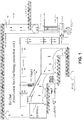
FIG 1 . is a schematic view of a biomass gasification system for use with high ash feedstocks. -
FIG. 2 is a top view of auger system for controlling the movement of biomass through the gasification system. - The general principle is that, by controlling the air and biomass movement through the unit, higher or lower levels of carbon in the ash may be developed and maximize the ash's value as both a fertilizer and/or method of holding carbon in the soil for long periods of time. The present invention provides a continuous system according to appended claim 1 and a method according to appended claim 5.
- The present system is particularly well suited for on-site heat production as part of larger facility. However, it is conceivable that the present system could be used to utilize high ash biomass as an energy source for electricity production.
- Referring to
FIG. 1 , fuel is introduced to a dryer. While generally any biomass material may be used, the present system is most advantageous in its handling of high ash feedstocks such as animal manure. - Biomass fuel generally contains large amounts of moisture. There are a number of methods for removing the moisture. In some embodiments, a commercial dryer may be added to the system. This will not be required with all biomass fuels. Standard equipment would also be used to introduce material to the front end of the gasification process.
- After conditioning of the fuel it is introduced and moved with augers through the various zones. The speed of these augers is controlled so that the material is being taken away at the same speed that it is introduced. This not only produces a continuous process but also allows for fine control of the rate and extent of reaction. With this process, the amount of the fixed carbon that will be left in the char may be adjusted by varying the feedstock feed rate as well as the feed rates of air as it is added in different zones of the process.
- The augers (as shown in
FIG. 2 ) lie side by side forming a live floor that moves material evenly across the length and width of the unit. A char removal auger is also shown running transverse to the direction of the other augers. The fuel and char may be maintained at levels to prevent excess air from entering the unit. - In the "reaction zone", a portion of the volatile carbon material and possibly some of the fixed carbon are oxidized to produce enough heat to drive off the volatiles in the rest of the biomass material. In some embodiments, approximately 1/4 of the air required for complete oxidation is introduced into this zone, however, this amount may vary depending on conditions and biomass.
- Air is introduced using a rotary air delivery system. Testing has shown that by keeping the air and biomass fuel moving, high temperature zones (hotspots) can be avoided and reduce or eliminate crusting and/or agglomerate formation. A rotary air system may ensure that material can pass through this zone without problems. The combination of moving air and the disturbance to the biomass material around the "disc" design shown will continuously bring new material into and through the reaction zone. This will generate considerable heat energy and a producer gas with high levels of CO and H2 with other volatile compounds. This producer gas can then be used for various applications such as being fired in a low BTU combustion engine or turbine. Alternatively, the producer gas may be oxidized in a second chamber to produce a high temperature oxidized flue gas for use in downstream equipment such as boilers or hot oil heat exchangers.
- The producer gas passes up over the fuel and is combined with the volatiles from the char cooling area as well as the drying and conditioning areas of the gasifier. This process will transfer some of the heat down through the fuel being introduced and help with the drying of the material before it reaches the air in the reaction zone. The resulting gas from the total process will then go to a second chamber where the rest of the air required for complete oxidation is added or the gas could be cleaned for other applications. Alternative processes could include the catalytic oxidation of all or a portion of the producer gas.
- In an exemplary embodiment, the producer gas from the unit will generally be in the 400 to 600 C. range and contain levels of CO, CO2, and H2 as well as other compounds. When oxidized in the upper chamber the resulting flue gas may typically be in the 1200 C. range. This flue gas can then be used for other energy applications.
- The resulting char is removed from the unit. A level of char is maintained in the unit to prevent air from entering into the reaction area. The quantitative qualities of the char can be adjusted to meet market demands by speeding up the flow or slowing it down, or adjusting the amount of air introduced into the various regions. When the char is cooled, relatively high levels of CO may be released. This will pass up over the gasifier reacting area as well as the fuel conditioning area to be added to the producer gas going to the oxidizer.
- All aspects of the system may be controlled by a programmable logic controller. Feed back loops may be established based on gas and char temperatures at various points in the process. Automated adjustments may be made to the dwell time of the fuel in various zones of the process or in the amount of air introduced to maintain a consistent biochar.
- In the following examples, a new gasification technology was used to integrate farm wastes into fertilizer and energy. A carbon rich product called biochar is generated from this process. Biochar is mainly produced from the pyrolysis of crop and animal manure. Biochar is understood to be a valuable material for its improving stability in soil and nutrient retention properties, which could be beneficial for the environment and in certain agricultural applications.
- Five biochar samples (summarized in Table 1) produced using the methods described herein were tested.
Table 1. Samples Sample ID Description Location 6077 Frye Poultry-broiler manure Wardensville, WV 6078 P&J- Turkey litter Northfield, MN 6079 Egg layer manure without Carbon Carterville, IL 6080 Egg layer manure with Carbon Carterville, IL 6082 Horse muck Carterville, IL - The samples were investigated for the chemical and mineral content and mineral release capacity by X-Ray Fluorescence Spectroscopy (XRF), X-Ray Di-fraction Spectroscopy (XRD). Carbon-Sulfur Analyzer, Inductively Couple Plasma Spectroscopy (ICP) and Phosphate Analyzer.
- Elemental data were obtained from XRF with a universal method: however this is not a calibrated method. Therefore the data presented in Table 2 should be considered semi quantitative except for the sulfur and carbon data shown in first two rows. Both carbon and sulfur data were obtained from Leco C-S Analyzer. Calcium, Potassium and Phosphorus are the dominant elements detected through out the samples. The table below list the major components detected, for the full list of elements detected please refer to the appendix.
Table 2. Elemental analysis of Biochar samples % 6077 6078 6079 6080 6082 Frye P&J No C With C Horse muck Sulfur 1.75 1.4 0.41 0.62 0.18 Carbon 21.9 9.52 3.45 7.9 15.4 Calcium 16.8 21.7 54.4 35.2 35.8 Silicon 2.3 3.51 0.6 5.5 8.4 Phosphorus 7.1 9.9 3.8 4.9 3.7 Potassium 16.2 13.2 5.5 4.7 5.8 Aluminum 1.6 0.9 0.2 2 2.3 Magnesium 3.5 4.4 1.6 2.3 2 Sodium 2.7 - - - - Iron 2.1 1.3 0.9 5.7 2 Chloride 5.7 - - - - Table 3 summarizes the chemical composition of minerals determined by XRD. The Biochar from Frye -broiler manure shows some variability in the chemical composition compared to the rest of the samples. Potassium sodium calcium phosphate, sylvite, quartz, and calcite are the most common minerals found within all of the Biochar samples. % 6077 6078 6079 6080 6082 Frye P&J PT No C PT With C Horse muck Sulfur, S 1.75 1.4 0.41 0.62 0.18 Carbon, C 21.9 9.52 3.45 7.9 15.4 Apthitalite, K3Na(SO4)2 24.9 - - - - Whitlockite, HCa9Mg(PO4)7 17.8 - - - - Sylvite, KCI 16.4 4.5 3.3 3.2 1.9 Quartz, SiO2 6.3 5.2 4.33 6.8 56.6 Calcite, CaCO3 5.7 4.5 18.6 6.8 14.4 Ammonium potassium Sulfate, NH4KSO4 4.6 - - - - Hematite, Fe2O3 3.8 - - - - Potassium sodium calcium phosphate, KNaCa2(PO)4 - 38 28.5 30.4 16.8 Potassium calcium magnesium phosphate, CaMgK(PO4)7 - 21.8 - - - Hydroxylapatite, Ca10(PO4)6.H2O - 17.6 16.4 18.7 7.8. Portlandite, Ca(OH)2 - - 28.3 10.2 1.9 Periclase, MgO - - 3.8 4.3 - Lime, CaO - - - 12.5 0.6 Others, amorphous 20.4 8.5 - 7.1 - - Among the biochar samples, the Frye broiler manure showed the highest carbon content. Therefore this sample was selected for the leachability study (TCLP: Toxicity Characteristic Leaching Procedure) and further processed through a lab oxidation process to remove the carbon. The ash obtained from oxidation was compared to the original sample by -MLR The TCLP samples were prepared under neutral conditions to have a true comparison to leachability in the field. This experiment was conducted to compare straight oxidation of the manure rather than gasification where retained carbon may aid in the slow release of the fertilizer into the plant and the environment. The results of leachable metals, total nitrogen, phosphorus, total sulfur and carbon in neutral water leachate were shown in Table 4.


- The elemental analysis shows that the process may be adjusted to control the carbon content that is retained in the gasification process. The mineral content surely depends on the type of feedstock. The composition of manure varies significantly from chickens (broiler vs. egg layer), turkeys, and horses. Biochar from horse manure is the case appears to be from grazing based on the high silica content. The process appears to remove significant nitrogen in the gasification process.
- The leachability study took the highest fixed carbon gasified manure (6077) and oxidized the carbon away to simulate burning (oxidizing) rather than gasification. This ensured removal of carbon from the manure leaving only oxidized mineral matter. The difference between gasified and oxidized samples in their leachability should be related to fixed carbon in the gasified samples retaining or slowing the release of these minerals into the water. Since the gasified sample contained 21% carbon there will be 21% higher concentration of the minerals in the oxidized sample. The results from the leachability found that the minerals in the gasified sample were only marginally different than the oxidized sample. Again it would be expected that metals in the oxidized sample should be 20% higher due to a more concentrated (no or less carbon)
mineral being present. Total nitrogen was virtually unchanged. However phosphorous was reduced significantly when gasified which would support a slower release to plant and the environment. Chrome also showed a significant reduction when gasified. Overall the study found that gasified manure may have some benefits over oxidized manure. - Additional testing was conducted using cattle manure was also conducted according to the methods described above. The gasification system has proven to effectively process a variety of fuels to produce a quality biochar product. The specific quality of the biochar is dependent on the composition of the fuel. Cow or cattle manure is one of the fuels that have been gasified and shown to produce a valuable biochar product. The quality of the biochar will vary slightly with cow manure depending on the animal diet, but can have a fairly large variation depending on the material handling methods employed on the farm where the manure is generated. Additionally, the gasification process also has some control over the quality; especially in the area of carbon content. An example of a biochar product from cow manure is shown in the mineral analysis shown in table 5.

Claims (13)
- A continuous system for gasification of a biomass feedstock comprising:a fuel conditioning zone;a gasification zone, the gasification zone including a controllable system for introducing air into the biomass in the gasification zone; wherein the controllable system for introducing air into the biomass in the gasification zone is a rotary air delivery system for moving the air and the biomass to avoid high temperature zones and to reduce or eliminate crusting and/or agglomerate formation;a char cooling area, the char cooling area having a gas capturing system for recovering gas released by the char as it cools;wherein the carbon content of the char may be adjusted by varying one or more of the feed rate of the fuel and air into the system and wherein the system comprises augers to introduce and move the fuel through the system and wherein the speed of the augers is controlled so that the material is being taken away at the same speed that it is introduced.
- The system of claim 1, wherein the gas capturing system of the char cooling area includes a gas return to direct at least a portion of the captured gas to the gasification zone.
- The system of claim 1, wherein the augers lie side by side forming a live floor that moves material evenly across the length and width of the zones or areas in the system.
- The system of claim 1, wherein the rotary air delivery system has a disc design.
- A method of operating a continuous system for gasification of a biomass feedstock comprising:introducing a biomass feedstock into a fuel conditioning zone;introducing and moving the product of the fuel conditioning zone into and through a gasification zone with augers, the gasification zone including a controllable system for introducing air into the biomass in the gasification zone;introducing air into the biomass in the gasification zone, the air being introduced at a level below that required for complete combustion of the feedstock, wherein the controllable system is a rotary air delivery system for moving the air and the biomass to avoid high temperature zones and to reduce or eliminate crusting and/or agglomerate formation;introducing a char product from the gasification zone into a char cooling area with augers, the char cooling area having a gas capturing system for recovering gas released by the char as it cools and routing the captured gas to the gasification zone;removing char from the char cooling area with a char removal auger, and wherein the speed of the augers is controlled so that the material is being taken away at the same speed that it is introduced.
- The method of claim 5, wherein the feedstock is pre-heated in the fuel conditioning zone.
- The method of claims 5 or 6, wherein air is introduced into the gasification zone at a level of less than 50% of that required for complete combustion.
- The method of claims 5 or 6, wherein air is introduced into the gasification zone at a level of less than 25% of that required for complete combustion.
- The method of claims 5 or 6, wherein air is introduced into the gasification zone at a level of 25% of that required for complete combustion.
- The method of claims 5 or 6, wherein the biomass feedstock is animal manure.
- The method of claim 5, wherein the gasification zone is operated with a gas outlet temperature of 400 to 600°C.
- The method of claim 11, wherein the gas removed is combusted in a secondary combustion chamber.
- The method of claim 5, wherein the rotary air delivery system has a disc design.
Applications Claiming Priority (3)
| Application Number | Priority Date | Filing Date | Title |
|---|---|---|---|
| US201261595253P | 2012-02-06 | 2012-02-06 | |
| US201361755493P | 2013-01-23 | 2013-01-23 | |
| PCT/US2013/024870 WO2013126211A1 (en) | 2012-02-06 | 2013-02-06 | Method and system for gasification of biomass |
Publications (3)
| Publication Number | Publication Date |
|---|---|
| EP2812416A1 EP2812416A1 (en) | 2014-12-17 |
| EP2812416A4 EP2812416A4 (en) | 2015-09-23 |
| EP2812416B1 true EP2812416B1 (en) | 2019-04-10 |
Family
ID=49006112
Family Applications (1)
| Application Number | Title | Priority Date | Filing Date |
|---|---|---|---|
| EP13751926.0A Active EP2812416B1 (en) | 2012-02-06 | 2013-02-06 | Method and system for gasification of biomass |
Country Status (5)
| Country | Link |
|---|---|
| US (2) | US11613705B2 (en) |
| EP (1) | EP2812416B1 (en) |
| CN (1) | CN104220563B (en) |
| CA (1) | CA2863146C (en) |
| WO (1) | WO2013126211A1 (en) |
Families Citing this family (17)
| Publication number | Priority date | Publication date | Assignee | Title |
|---|---|---|---|---|
| EP4219660A3 (en) | 2011-04-15 | 2023-10-18 | Carbon Technology Holdings, LLC | Processes for producing high-carbon biogenic reagents |
| US9809768B2 (en) * | 2015-12-04 | 2017-11-07 | Lubor JANCOK | Device for the production of fuel gas from materials of organic and/or inorganic origin |
| US10436525B2 (en) | 2016-05-12 | 2019-10-08 | Golden Renewable Energy, LLC | Cyclonic cooling system |
| MX2018013717A (en) | 2016-05-12 | 2019-06-20 | Golden Renewable Energy Llc | Cyclonic condensing and cooling system. |
| WO2017208250A1 (en) * | 2016-06-01 | 2017-12-07 | Council Of Scientific And Industrial Research | A method for production of potash enriched biochar from waste biomass |
| CR20190020A (en) * | 2016-06-21 | 2019-04-25 | Golden Renewable Energy Llc | CARBON SEPARATOR AND METHOD |
| US20170361268A1 (en) | 2016-06-21 | 2017-12-21 | Golden Renewable Energy | Char separator |
| US10961062B2 (en) | 2016-06-21 | 2021-03-30 | Golden Renewable Energy, LLC | Bag press feeder assembly |
| NZ749216A (en) | 2016-07-05 | 2020-05-29 | Golden Renewable Energy Llc | System and process for converting waste plastic into fuel |
| CN108998059A (en) * | 2018-08-15 | 2018-12-14 | 佛山市北科科技创新服务中心 | A kind of animal husbandry waste charing process equipment |
| RU2736739C1 (en) * | 2020-06-02 | 2020-11-19 | Закрытое акционерное общество «Краснобор» | Method and system for bedding gasification of poultry floor housing |
| EP4217520A1 (en) | 2020-09-25 | 2023-08-02 | Carbon Technology Holdings, LLC | Bio-reduction of metal ores integrated with biomass pyrolysis |
| JP2024508270A (en) | 2021-02-18 | 2024-02-26 | カーボン テクノロジー ホールディングス, エルエルシー | carbon negative metallurgy products |
| US20220396529A1 (en) | 2021-04-27 | 2022-12-15 | Carbon Technology Holdings, LLC | Biocarbon blends with optimized fixed carbon content, and methods for making and using the same |
| CA3225978A1 (en) | 2021-07-09 | 2023-01-12 | Carbon Technology Holdings, LLC | Processes for producing biocarbon pellets with high fixed-carbon content and optimized reactivity, and biocarbon pellets obtained therefrom |
| US20230150872A1 (en) * | 2021-11-12 | 2023-05-18 | Carbon Technology Holdings, LLC | Biocarbon compositions with optimized compositional parameters, and processes for producing the same |
| WO2024064208A1 (en) * | 2022-09-20 | 2024-03-28 | Mcgolden, Llc | Gasifier with a reaction zone and a cooling zone with alternately flighted augers and paddles |
Citations (1)
| Publication number | Priority date | Publication date | Assignee | Title |
|---|---|---|---|---|
| US5094669A (en) * | 1989-09-08 | 1992-03-10 | Metallgesellschaft Aktiengesellschaft | Method of controlling the gasification of solid fuels in a rotary-grate gas producer |
Family Cites Families (27)
| Publication number | Priority date | Publication date | Assignee | Title |
|---|---|---|---|---|
| ES2040367T3 (en) * | 1987-10-19 | 1993-10-16 | Biolandes Agro | LOADING-UNLOADING MECHANISM OF A CLOSED ENCLOSURE USABLE AS A TANK FOR EXTRACTION OF A CONTINUOUS EXTRACTION UNIT OF VEGETABLES, AND EXTRACTION PROCEDURE THAT INCLUDES THE APPLICATION. |
| US4764185A (en) * | 1987-10-28 | 1988-08-16 | Mayer Edward F | Gasifier apparatus |
| US5096463A (en) | 1988-05-06 | 1992-03-17 | American Power & Waste Management Ltd. | Gasifier adapted to generate activated carbon |
| US5589599A (en) * | 1994-06-07 | 1996-12-31 | Mcmullen; Frederick G. | Pyrolytic conversion of organic feedstock and waste |
| US5720165A (en) * | 1995-09-21 | 1998-02-24 | Bioten Gp | System for burning biomass to produce hot gas |
| US5601692A (en) * | 1995-12-01 | 1997-02-11 | Tek-Kol Partnership | Process for treating noncaking coal to form passivated char |
| EP1312662A3 (en) | 2001-05-07 | 2003-09-24 | Cirad-Foret | Biomass gasification process, and apparatus, and their applications |
| US6485296B1 (en) * | 2001-10-03 | 2002-11-26 | Robert J. Bender | Variable moisture biomass gasification heating system and method |
| US8317886B2 (en) * | 2002-05-22 | 2012-11-27 | Nexterra Systems Corp. | Apparatus and method for gasifying solid organic materials |
| JP2006083293A (en) | 2004-09-16 | 2006-03-30 | Fuji Electric Systems Co Ltd | Gasification apparatus of biomass fuel |
| JP2006335956A (en) | 2005-06-03 | 2006-12-14 | Sumitomo Metal Ind Ltd | Method of recovering surplus offgas in coke dry quenching equipment |
| EP1896368B1 (en) * | 2005-06-28 | 2013-05-01 | Afognak Native Corporation | Method and apparatus for automated, modular, biomass power generation |
| NZ573217A (en) * | 2006-05-05 | 2011-11-25 | Plascoenergy Ip Holdings S L Bilbao Schaffhausen Branch | A facility for conversion of carbonaceous feedstock into a reformulated syngas containing CO and H2 |
| TR200705430A2 (en) * | 2007-08-03 | 2008-12-22 | Detes Maden Enerji̇ Ve Çevre Teknoloji̇si̇ Si̇stemleri̇ Li̇mi̇ted Şi̇rketi̇ | Solid fuel gasification and gas cleaning system. |
| CN101245250A (en) * | 2008-03-19 | 2008-08-20 | 北京林业大学 | Energy comprehensive utilization method for lignification biomass material |
| AU2009235959A1 (en) | 2008-04-10 | 2009-10-15 | The Crucible Group Pty Ltd | Processing organic materials |
| US8669404B2 (en) * | 2008-10-15 | 2014-03-11 | Renewable Fuel Technologies, Inc. | Method for conversion of biomass to biofuel |
| CN101412929B (en) * | 2008-11-28 | 2012-02-01 | 武汉凯迪工程技术研究总院有限公司 | High temperature gasification technological process and system for preparing synthesis gas by using biomass |
| CN201348276Y (en) | 2009-01-19 | 2009-11-18 | 陈强 | Gasification furnace for combustible matter |
| FR2945294B1 (en) * | 2009-05-07 | 2012-04-20 | Olivier Lepez | METHOD AND INSTALLATION FOR ENERGETIC DENSIFICATION OF A PRODUCT IN THE FORM OF DIVIDED SOLIDS FOR OBTAINING ENERGY-EFFICIENT PYROLYTIC OILS |
| US7947155B1 (en) * | 2009-11-17 | 2011-05-24 | Green Liquid and Gas Technologies | Process and device for the pyrolysis of feedstock |
| CN101781585B (en) | 2010-03-10 | 2012-12-12 | 周少海 | Gasification agent injection device of biomass gasifier |
| CH703513B1 (en) | 2010-07-27 | 2014-09-30 | St V Sa | Furnace for granular material to be burned, for services down to less than 1 kW, with means for Brenngutzufuhr and the ash crushing and distribution. |
| CN201952404U (en) | 2010-12-14 | 2011-08-31 | 许荣根 | Environment-friendly backfire clean coking and gas making power generation poly-generation device |
| CN201999893U (en) | 2011-01-10 | 2011-10-05 | 周仁福 | Open type multifunctional pyrolyzing furnace for agricultural wastes |
| US8100990B2 (en) * | 2011-05-15 | 2012-01-24 | Avello Bioenery, Inc. | Methods for integrated fast pyrolysis processing of biomass |
| US9446975B2 (en) * | 2011-10-21 | 2016-09-20 | Therma-Flite, Inc. | Gasifying system and method |
-
2013
- 2013-02-06 CN CN201380008372.2A patent/CN104220563B/en active Active
- 2013-02-06 WO PCT/US2013/024870 patent/WO2013126211A1/en active Application Filing
- 2013-02-06 US US14/356,977 patent/US11613705B2/en active Active
- 2013-02-06 CA CA2863146A patent/CA2863146C/en active Active
- 2013-02-06 EP EP13751926.0A patent/EP2812416B1/en active Active
-
2023
- 2023-03-27 US US18/126,563 patent/US20230348789A1/en active Pending
Patent Citations (1)
| Publication number | Priority date | Publication date | Assignee | Title |
|---|---|---|---|---|
| US5094669A (en) * | 1989-09-08 | 1992-03-10 | Metallgesellschaft Aktiengesellschaft | Method of controlling the gasification of solid fuels in a rotary-grate gas producer |
Also Published As
| Publication number | Publication date |
|---|---|
| US11613705B2 (en) | 2023-03-28 |
| US20230348789A1 (en) | 2023-11-02 |
| CN104220563A (en) | 2014-12-17 |
| CA2863146C (en) | 2021-04-06 |
| CA2863146A1 (en) | 2013-08-29 |
| EP2812416A4 (en) | 2015-09-23 |
| EP2812416A1 (en) | 2014-12-17 |
| WO2013126211A1 (en) | 2013-08-29 |
| US20140332363A1 (en) | 2014-11-13 |
| CN104220563B (en) | 2017-07-11 |
Similar Documents
| Publication | Publication Date | Title |
|---|---|---|
| EP2812416B1 (en) | Method and system for gasification of biomass | |
| US20080317657A1 (en) | Systems and methods for capturing, isolating and sequestering carbon from CO2 in the atmosphere in the form of char produced from biomass feedstock | |
| JP5246663B2 (en) | Method for recovering phosphorus compounds | |
| Pandey et al. | Poultry litter gasification in a fluidized bed reactor: effects of gasifying agent and limestone addition | |
| EP2614128B1 (en) | Fluidised bed pyrolysis apparatus and method | |
| JP6899102B2 (en) | Biomass gasifier | |
| JP2007196214A (en) | Method for effective use of biomass combustion ashes | |
| Guo et al. | Thermochemical processing of animal manure for bioenergy and biochar | |
| CN111278776A (en) | Nutrient and energy recovery from sewage sludge and animal manure | |
| CN101434461A (en) | Apparatus and method for processing wastes | |
| JP6806382B2 (en) | How to recover phosphorus | |
| Uchimiya | Changes in nutrient content and availability during the slow pyrolysis of animal wastes | |
| US20160075608A1 (en) | Production of nutrient-rich biochar from a residual material | |
| JP4396843B2 (en) | Multi-stage fluidized bed combustion method | |
| JP4355667B2 (en) | Method for producing valuable materials from livestock manure | |
| EP2992268B1 (en) | Process and plant for separating heavy metals from phosphorus-containing starting material | |
| Sosnowska et al. | Formation of fireside deposits in feather gasification and heat recovery systems—an industrial case study | |
| Priyadarsan et al. | Waste to energy: fixed bed gasification of feedlot and chicken litter biomass | |
| Chen | Pyrolysis and Combustion of Phosphorus containing Solid Fuels: Char Structure, Char Reactivity and Particulate Matter Emission | |
| JP2023094850A (en) | Reconstruction method of biomass processing system | |
| Hains et al. | Exploration of Renewable Energy Usage in a Cement Kiln Using Downdraft Gasification of Poultry Litter | |
| PL206550B1 (en) | Method for the processing organic wastes and device for processing organic wastes |
Legal Events
| Date | Code | Title | Description |
|---|---|---|---|
| PUAI | Public reference made under article 153(3) epc to a published international application that has entered the european phase |
Free format text: ORIGINAL CODE: 0009012 |
|
| 17P | Request for examination filed |
Effective date: 20140724 |
|
| AK | Designated contracting states |
Kind code of ref document: A1 Designated state(s): AL AT BE BG CH CY CZ DE DK EE ES FI FR GB GR HR HU IE IS IT LI LT LU LV MC MK MT NL NO PL PT RO RS SE SI SK SM TR |
|
| AX | Request for extension of the european patent |
Extension state: BA ME |
|
| DAX | Request for extension of the european patent (deleted) | ||
| RA4 | Supplementary search report drawn up and despatched (corrected) |
Effective date: 20150820 |
|
| RIC1 | Information provided on ipc code assigned before grant |
Ipc: B09B 3/00 20060101ALI20150814BHEP Ipc: C10J 3/72 20060101ALI20150814BHEP Ipc: C10J 3/30 20060101ALI20150814BHEP Ipc: C05F 11/00 20060101ALI20150814BHEP Ipc: C10B 53/00 20060101ALI20150814BHEP Ipc: F23G 5/027 20060101AFI20150814BHEP Ipc: C10L 5/42 20060101ALI20150814BHEP Ipc: F23J 1/02 20060101ALI20150814BHEP Ipc: C10B 49/04 20060101ALI20150814BHEP Ipc: C10B 57/10 20060101ALI20150814BHEP |
|
| STAA | Information on the status of an ep patent application or granted ep patent |
Free format text: STATUS: EXAMINATION IS IN PROGRESS |
|
| 17Q | First examination report despatched |
Effective date: 20170302 |
|
| GRAP | Despatch of communication of intention to grant a patent |
Free format text: ORIGINAL CODE: EPIDOSNIGR1 |
|
| STAA | Information on the status of an ep patent application or granted ep patent |
Free format text: STATUS: GRANT OF PATENT IS INTENDED |
|
| INTG | Intention to grant announced |
Effective date: 20181008 |
|
| RAP1 | Party data changed (applicant data changed or rights of an application transferred) |
Owner name: MCGOLDEN, LLC |
|
| RIN1 | Information on inventor provided before grant (corrected) |
Inventor name: MCGOLDEN, LLC |
|
| GRAS | Grant fee paid |
Free format text: ORIGINAL CODE: EPIDOSNIGR3 |
|
| GRAA | (expected) grant |
Free format text: ORIGINAL CODE: 0009210 |
|
| STAA | Information on the status of an ep patent application or granted ep patent |
Free format text: STATUS: THE PATENT HAS BEEN GRANTED |
|
| RIN1 | Information on inventor provided before grant (corrected) |
Inventor name: MCGOLDEN, MICHAEL |
|
| AK | Designated contracting states |
Kind code of ref document: B1 Designated state(s): AL AT BE BG CH CY CZ DE DK EE ES FI FR GB GR HR HU IE IS IT LI LT LU LV MC MK MT NL NO PL PT RO RS SE SI SK SM TR |
|
| REG | Reference to a national code |
Ref country code: GB Ref legal event code: FG4D |
|
| REG | Reference to a national code |
Ref country code: CH Ref legal event code: EP Ref country code: AT Ref legal event code: REF Ref document number: 1119193 Country of ref document: AT Kind code of ref document: T Effective date: 20190415 |
|
| REG | Reference to a national code |
Ref country code: DE Ref legal event code: R096 Ref document number: 602013053707 Country of ref document: DE |
|
| REG | Reference to a national code |
Ref country code: IE Ref legal event code: FG4D |
|
| REG | Reference to a national code |
Ref country code: NL Ref legal event code: FP |
|
| REG | Reference to a national code |
Ref country code: LT Ref legal event code: MG4D |
|
| REG | Reference to a national code |
Ref country code: AT Ref legal event code: MK05 Ref document number: 1119193 Country of ref document: AT Kind code of ref document: T Effective date: 20190410 |
|
| PG25 | Lapsed in a contracting state [announced via postgrant information from national office to epo] |
Ref country code: ES Free format text: LAPSE BECAUSE OF FAILURE TO SUBMIT A TRANSLATION OF THE DESCRIPTION OR TO PAY THE FEE WITHIN THE PRESCRIBED TIME-LIMIT Effective date: 20190410 Ref country code: LT Free format text: LAPSE BECAUSE OF FAILURE TO SUBMIT A TRANSLATION OF THE DESCRIPTION OR TO PAY THE FEE WITHIN THE PRESCRIBED TIME-LIMIT Effective date: 20190410 Ref country code: HR Free format text: LAPSE BECAUSE OF FAILURE TO SUBMIT A TRANSLATION OF THE DESCRIPTION OR TO PAY THE FEE WITHIN THE PRESCRIBED TIME-LIMIT Effective date: 20190410 Ref country code: FI Free format text: LAPSE BECAUSE OF FAILURE TO SUBMIT A TRANSLATION OF THE DESCRIPTION OR TO PAY THE FEE WITHIN THE PRESCRIBED TIME-LIMIT Effective date: 20190410 Ref country code: AL Free format text: LAPSE BECAUSE OF FAILURE TO SUBMIT A TRANSLATION OF THE DESCRIPTION OR TO PAY THE FEE WITHIN THE PRESCRIBED TIME-LIMIT Effective date: 20190410 Ref country code: SE Free format text: LAPSE BECAUSE OF FAILURE TO SUBMIT A TRANSLATION OF THE DESCRIPTION OR TO PAY THE FEE WITHIN THE PRESCRIBED TIME-LIMIT Effective date: 20190410 Ref country code: PT Free format text: LAPSE BECAUSE OF FAILURE TO SUBMIT A TRANSLATION OF THE DESCRIPTION OR TO PAY THE FEE WITHIN THE PRESCRIBED TIME-LIMIT Effective date: 20190910 Ref country code: NO Free format text: LAPSE BECAUSE OF FAILURE TO SUBMIT A TRANSLATION OF THE DESCRIPTION OR TO PAY THE FEE WITHIN THE PRESCRIBED TIME-LIMIT Effective date: 20190710 |
|
| PG25 | Lapsed in a contracting state [announced via postgrant information from national office to epo] |
Ref country code: LV Free format text: LAPSE BECAUSE OF FAILURE TO SUBMIT A TRANSLATION OF THE DESCRIPTION OR TO PAY THE FEE WITHIN THE PRESCRIBED TIME-LIMIT Effective date: 20190410 Ref country code: GR Free format text: LAPSE BECAUSE OF FAILURE TO SUBMIT A TRANSLATION OF THE DESCRIPTION OR TO PAY THE FEE WITHIN THE PRESCRIBED TIME-LIMIT Effective date: 20190711 Ref country code: PL Free format text: LAPSE BECAUSE OF FAILURE TO SUBMIT A TRANSLATION OF THE DESCRIPTION OR TO PAY THE FEE WITHIN THE PRESCRIBED TIME-LIMIT Effective date: 20190410 Ref country code: RS Free format text: LAPSE BECAUSE OF FAILURE TO SUBMIT A TRANSLATION OF THE DESCRIPTION OR TO PAY THE FEE WITHIN THE PRESCRIBED TIME-LIMIT Effective date: 20190410 Ref country code: BG Free format text: LAPSE BECAUSE OF FAILURE TO SUBMIT A TRANSLATION OF THE DESCRIPTION OR TO PAY THE FEE WITHIN THE PRESCRIBED TIME-LIMIT Effective date: 20190710 |
|
| PG25 | Lapsed in a contracting state [announced via postgrant information from national office to epo] |
Ref country code: AT Free format text: LAPSE BECAUSE OF FAILURE TO SUBMIT A TRANSLATION OF THE DESCRIPTION OR TO PAY THE FEE WITHIN THE PRESCRIBED TIME-LIMIT Effective date: 20190410 Ref country code: IS Free format text: LAPSE BECAUSE OF FAILURE TO SUBMIT A TRANSLATION OF THE DESCRIPTION OR TO PAY THE FEE WITHIN THE PRESCRIBED TIME-LIMIT Effective date: 20190810 |
|
| REG | Reference to a national code |
Ref country code: DE Ref legal event code: R097 Ref document number: 602013053707 Country of ref document: DE |
|
| PG25 | Lapsed in a contracting state [announced via postgrant information from national office to epo] |
Ref country code: CZ Free format text: LAPSE BECAUSE OF FAILURE TO SUBMIT A TRANSLATION OF THE DESCRIPTION OR TO PAY THE FEE WITHIN THE PRESCRIBED TIME-LIMIT Effective date: 20190410 Ref country code: RO Free format text: LAPSE BECAUSE OF FAILURE TO SUBMIT A TRANSLATION OF THE DESCRIPTION OR TO PAY THE FEE WITHIN THE PRESCRIBED TIME-LIMIT Effective date: 20190410 Ref country code: SK Free format text: LAPSE BECAUSE OF FAILURE TO SUBMIT A TRANSLATION OF THE DESCRIPTION OR TO PAY THE FEE WITHIN THE PRESCRIBED TIME-LIMIT Effective date: 20190410 Ref country code: EE Free format text: LAPSE BECAUSE OF FAILURE TO SUBMIT A TRANSLATION OF THE DESCRIPTION OR TO PAY THE FEE WITHIN THE PRESCRIBED TIME-LIMIT Effective date: 20190410 Ref country code: DK Free format text: LAPSE BECAUSE OF FAILURE TO SUBMIT A TRANSLATION OF THE DESCRIPTION OR TO PAY THE FEE WITHIN THE PRESCRIBED TIME-LIMIT Effective date: 20190410 |
|
| PLBE | No opposition filed within time limit |
Free format text: ORIGINAL CODE: 0009261 |
|
| STAA | Information on the status of an ep patent application or granted ep patent |
Free format text: STATUS: NO OPPOSITION FILED WITHIN TIME LIMIT |
|
| PG25 | Lapsed in a contracting state [announced via postgrant information from national office to epo] |
Ref country code: IT Free format text: LAPSE BECAUSE OF FAILURE TO SUBMIT A TRANSLATION OF THE DESCRIPTION OR TO PAY THE FEE WITHIN THE PRESCRIBED TIME-LIMIT Effective date: 20190410 Ref country code: SM Free format text: LAPSE BECAUSE OF FAILURE TO SUBMIT A TRANSLATION OF THE DESCRIPTION OR TO PAY THE FEE WITHIN THE PRESCRIBED TIME-LIMIT Effective date: 20190410 |
|
| 26N | No opposition filed |
Effective date: 20200113 |
|
| PG25 | Lapsed in a contracting state [announced via postgrant information from national office to epo] |
Ref country code: TR Free format text: LAPSE BECAUSE OF FAILURE TO SUBMIT A TRANSLATION OF THE DESCRIPTION OR TO PAY THE FEE WITHIN THE PRESCRIBED TIME-LIMIT Effective date: 20190410 |
|
| PG25 | Lapsed in a contracting state [announced via postgrant information from national office to epo] |
Ref country code: SI Free format text: LAPSE BECAUSE OF FAILURE TO SUBMIT A TRANSLATION OF THE DESCRIPTION OR TO PAY THE FEE WITHIN THE PRESCRIBED TIME-LIMIT Effective date: 20190410 |
|
| REG | Reference to a national code |
Ref country code: CH Ref legal event code: PL |
|
| REG | Reference to a national code |
Ref country code: BE Ref legal event code: MM Effective date: 20200229 |
|
| PG25 | Lapsed in a contracting state [announced via postgrant information from national office to epo] |
Ref country code: MC Free format text: LAPSE BECAUSE OF FAILURE TO SUBMIT A TRANSLATION OF THE DESCRIPTION OR TO PAY THE FEE WITHIN THE PRESCRIBED TIME-LIMIT Effective date: 20190410 Ref country code: LU Free format text: LAPSE BECAUSE OF NON-PAYMENT OF DUE FEES Effective date: 20200206 |
|
| PG25 | Lapsed in a contracting state [announced via postgrant information from national office to epo] |
Ref country code: LI Free format text: LAPSE BECAUSE OF NON-PAYMENT OF DUE FEES Effective date: 20200229 Ref country code: CH Free format text: LAPSE BECAUSE OF NON-PAYMENT OF DUE FEES Effective date: 20200229 |
|
| PG25 | Lapsed in a contracting state [announced via postgrant information from national office to epo] |
Ref country code: IE Free format text: LAPSE BECAUSE OF NON-PAYMENT OF DUE FEES Effective date: 20200206 Ref country code: FR Free format text: LAPSE BECAUSE OF NON-PAYMENT OF DUE FEES Effective date: 20200229 |
|
| PG25 | Lapsed in a contracting state [announced via postgrant information from national office to epo] |
Ref country code: BE Free format text: LAPSE BECAUSE OF NON-PAYMENT OF DUE FEES Effective date: 20200229 |
|
| PG25 | Lapsed in a contracting state [announced via postgrant information from national office to epo] |
Ref country code: MT Free format text: LAPSE BECAUSE OF FAILURE TO SUBMIT A TRANSLATION OF THE DESCRIPTION OR TO PAY THE FEE WITHIN THE PRESCRIBED TIME-LIMIT Effective date: 20190410 Ref country code: CY Free format text: LAPSE BECAUSE OF FAILURE TO SUBMIT A TRANSLATION OF THE DESCRIPTION OR TO PAY THE FEE WITHIN THE PRESCRIBED TIME-LIMIT Effective date: 20190410 |
|
| PG25 | Lapsed in a contracting state [announced via postgrant information from national office to epo] |
Ref country code: MK Free format text: LAPSE BECAUSE OF FAILURE TO SUBMIT A TRANSLATION OF THE DESCRIPTION OR TO PAY THE FEE WITHIN THE PRESCRIBED TIME-LIMIT Effective date: 20190410 |
|
| P01 | Opt-out of the competence of the unified patent court (upc) registered |
Effective date: 20230520 |
|
| PGFP | Annual fee paid to national office [announced via postgrant information from national office to epo] |
Ref country code: NL Payment date: 20240226 Year of fee payment: 12 |
|
| PGFP | Annual fee paid to national office [announced via postgrant information from national office to epo] |
Ref country code: DE Payment date: 20240228 Year of fee payment: 12 Ref country code: GB Payment date: 20240227 Year of fee payment: 12 |