EP2811901B1 - Extension d'une bibliothèque de référence pendant la mise en image d'organes en mouvement - Google Patents
Extension d'une bibliothèque de référence pendant la mise en image d'organes en mouvement Download PDFInfo
- Publication number
- EP2811901B1 EP2811901B1 EP13717851.3A EP13717851A EP2811901B1 EP 2811901 B1 EP2811901 B1 EP 2811901B1 EP 13717851 A EP13717851 A EP 13717851A EP 2811901 B1 EP2811901 B1 EP 2811901B1
- Authority
- EP
- European Patent Office
- Prior art keywords
- image
- treatment
- images
- library
- new
- Prior art date
- Legal status (The legal status is an assumption and is not a legal conclusion. Google has not performed a legal analysis and makes no representation as to the accuracy of the status listed.)
- Active
Links
- 238000003384 imaging method Methods 0.000 title claims description 45
- 210000000056 organ Anatomy 0.000 title description 11
- 238000011282 treatment Methods 0.000 claims description 221
- 210000003484 anatomy Anatomy 0.000 claims description 39
- 238000012544 monitoring process Methods 0.000 claims description 19
- 238000002604 ultrasonography Methods 0.000 claims description 17
- 230000001225 therapeutic effect Effects 0.000 claims description 9
- 238000010191 image analysis Methods 0.000 claims description 3
- 238000000034 method Methods 0.000 description 47
- 210000001519 tissue Anatomy 0.000 description 36
- 230000000875 corresponding effect Effects 0.000 description 23
- 238000012545 processing Methods 0.000 description 15
- 238000004861 thermometry Methods 0.000 description 15
- 230000008859 change Effects 0.000 description 8
- 238000002595 magnetic resonance imaging Methods 0.000 description 6
- 230000008569 process Effects 0.000 description 6
- 230000003466 anti-cipated effect Effects 0.000 description 5
- 238000009529 body temperature measurement Methods 0.000 description 5
- 230000006870 function Effects 0.000 description 5
- 238000005259 measurement Methods 0.000 description 5
- 230000004044 response Effects 0.000 description 5
- 238000013459 approach Methods 0.000 description 4
- 230000000241 respiratory effect Effects 0.000 description 4
- 230000003068 static effect Effects 0.000 description 4
- 238000007669 thermal treatment Methods 0.000 description 4
- 238000002591 computed tomography Methods 0.000 description 3
- 230000001276 controlling effect Effects 0.000 description 3
- 230000014509 gene expression Effects 0.000 description 3
- 238000010438 heat treatment Methods 0.000 description 3
- 238000000527 sonication Methods 0.000 description 3
- 230000008901 benefit Effects 0.000 description 2
- 230000036760 body temperature Effects 0.000 description 2
- 238000001514 detection method Methods 0.000 description 2
- 238000006073 displacement reaction Methods 0.000 description 2
- 230000000694 effects Effects 0.000 description 2
- 230000005415 magnetization Effects 0.000 description 2
- 230000000737 periodic effect Effects 0.000 description 2
- 230000029058 respiratory gaseous exchange Effects 0.000 description 2
- 238000001356 surgical procedure Methods 0.000 description 2
- XLYOFNOQVPJJNP-UHFFFAOYSA-N water Substances O XLYOFNOQVPJJNP-UHFFFAOYSA-N 0.000 description 2
- UFHFLCQGNIYNRP-UHFFFAOYSA-N Hydrogen Chemical compound [H][H] UFHFLCQGNIYNRP-UHFFFAOYSA-N 0.000 description 1
- 206010020843 Hyperthermia Diseases 0.000 description 1
- 241000270295 Serpentes Species 0.000 description 1
- 238000010521 absorption reaction Methods 0.000 description 1
- 238000004458 analytical method Methods 0.000 description 1
- 230000006399 behavior Effects 0.000 description 1
- 230000002457 bidirectional effect Effects 0.000 description 1
- 238000012512 characterization method Methods 0.000 description 1
- 238000006243 chemical reaction Methods 0.000 description 1
- 238000004891 communication Methods 0.000 description 1
- 238000005094 computer simulation Methods 0.000 description 1
- 238000012790 confirmation Methods 0.000 description 1
- 238000007796 conventional method Methods 0.000 description 1
- 238000001816 cooling Methods 0.000 description 1
- 230000002596 correlated effect Effects 0.000 description 1
- 230000001934 delay Effects 0.000 description 1
- 230000001419 dependent effect Effects 0.000 description 1
- 230000001066 destructive effect Effects 0.000 description 1
- 238000011161 development Methods 0.000 description 1
- 238000003745 diagnosis Methods 0.000 description 1
- 238000002059 diagnostic imaging Methods 0.000 description 1
- 238000010586 diagram Methods 0.000 description 1
- 230000005672 electromagnetic field Effects 0.000 description 1
- 238000013213 extrapolation Methods 0.000 description 1
- 229910052739 hydrogen Inorganic materials 0.000 description 1
- 239000001257 hydrogen Substances 0.000 description 1
- 230000036031 hyperthermia Effects 0.000 description 1
- 230000001939 inductive effect Effects 0.000 description 1
- 230000003993 interaction Effects 0.000 description 1
- 238000012986 modification Methods 0.000 description 1
- 230000004048 modification Effects 0.000 description 1
- 230000017074 necrotic cell death Effects 0.000 description 1
- 230000004007 neuromodulation Effects 0.000 description 1
- 238000001208 nuclear magnetic resonance pulse sequence Methods 0.000 description 1
- 230000003287 optical effect Effects 0.000 description 1
- 239000002245 particle Substances 0.000 description 1
- 210000002307 prostate Anatomy 0.000 description 1
- 230000005855 radiation Effects 0.000 description 1
- 210000004872 soft tissue Anatomy 0.000 description 1
- 230000000153 supplemental effect Effects 0.000 description 1
- 230000002123 temporal effect Effects 0.000 description 1
- 238000002560 therapeutic procedure Methods 0.000 description 1
- 238000009210 therapy by ultrasound Methods 0.000 description 1
- 230000001052 transient effect Effects 0.000 description 1
- 238000011277 treatment modality Methods 0.000 description 1
- 239000013598 vector Substances 0.000 description 1
Images


Classifications
-
- A—HUMAN NECESSITIES
- A61—MEDICAL OR VETERINARY SCIENCE; HYGIENE
- A61N—ELECTROTHERAPY; MAGNETOTHERAPY; RADIATION THERAPY; ULTRASOUND THERAPY
- A61N7/00—Ultrasound therapy
-
- A—HUMAN NECESSITIES
- A61—MEDICAL OR VETERINARY SCIENCE; HYGIENE
- A61B—DIAGNOSIS; SURGERY; IDENTIFICATION
- A61B5/00—Measuring for diagnostic purposes; Identification of persons
- A61B5/05—Detecting, measuring or recording for diagnosis by means of electric currents or magnetic fields; Measuring using microwaves or radio waves
- A61B5/055—Detecting, measuring or recording for diagnosis by means of electric currents or magnetic fields; Measuring using microwaves or radio waves involving electronic [EMR] or nuclear [NMR] magnetic resonance, e.g. magnetic resonance imaging
-
- A—HUMAN NECESSITIES
- A61—MEDICAL OR VETERINARY SCIENCE; HYGIENE
- A61N—ELECTROTHERAPY; MAGNETOTHERAPY; RADIATION THERAPY; ULTRASOUND THERAPY
- A61N7/00—Ultrasound therapy
- A61N7/02—Localised ultrasound hyperthermia
-
- G—PHYSICS
- G06—COMPUTING; CALCULATING OR COUNTING
- G06T—IMAGE DATA PROCESSING OR GENERATION, IN GENERAL
- G06T7/00—Image analysis
- G06T7/20—Analysis of motion
- G06T7/246—Analysis of motion using feature-based methods, e.g. the tracking of corners or segments
- G06T7/248—Analysis of motion using feature-based methods, e.g. the tracking of corners or segments involving reference images or patches
-
- G—PHYSICS
- G06—COMPUTING; CALCULATING OR COUNTING
- G06T—IMAGE DATA PROCESSING OR GENERATION, IN GENERAL
- G06T7/00—Image analysis
- G06T7/70—Determining position or orientation of objects or cameras
- G06T7/73—Determining position or orientation of objects or cameras using feature-based methods
- G06T7/74—Determining position or orientation of objects or cameras using feature-based methods involving reference images or patches
-
- A—HUMAN NECESSITIES
- A61—MEDICAL OR VETERINARY SCIENCE; HYGIENE
- A61B—DIAGNOSIS; SURGERY; IDENTIFICATION
- A61B17/00—Surgical instruments, devices or methods, e.g. tourniquets
- A61B2017/00017—Electrical control of surgical instruments
- A61B2017/00022—Sensing or detecting at the treatment site
- A61B2017/00084—Temperature
-
- A—HUMAN NECESSITIES
- A61—MEDICAL OR VETERINARY SCIENCE; HYGIENE
- A61B—DIAGNOSIS; SURGERY; IDENTIFICATION
- A61B90/00—Instruments, implements or accessories specially adapted for surgery or diagnosis and not covered by any of the groups A61B1/00 - A61B50/00, e.g. for luxation treatment or for protecting wound edges
- A61B90/36—Image-producing devices or illumination devices not otherwise provided for
- A61B90/37—Surgical systems with images on a monitor during operation
- A61B2090/374—NMR or MRI
-
- A—HUMAN NECESSITIES
- A61—MEDICAL OR VETERINARY SCIENCE; HYGIENE
- A61B—DIAGNOSIS; SURGERY; IDENTIFICATION
- A61B5/00—Measuring for diagnostic purposes; Identification of persons
- A61B5/01—Measuring temperature of body parts ; Diagnostic temperature sensing, e.g. for malignant or inflamed tissue
- A61B5/015—By temperature mapping of body part
-
- A—HUMAN NECESSITIES
- A61—MEDICAL OR VETERINARY SCIENCE; HYGIENE
- A61N—ELECTROTHERAPY; MAGNETOTHERAPY; RADIATION THERAPY; ULTRASOUND THERAPY
- A61N7/00—Ultrasound therapy
- A61N2007/0056—Beam shaping elements
-
- F—MECHANICAL ENGINEERING; LIGHTING; HEATING; WEAPONS; BLASTING
- F04—POSITIVE - DISPLACEMENT MACHINES FOR LIQUIDS; PUMPS FOR LIQUIDS OR ELASTIC FLUIDS
- F04C—ROTARY-PISTON, OR OSCILLATING-PISTON, POSITIVE-DISPLACEMENT MACHINES FOR LIQUIDS; ROTARY-PISTON, OR OSCILLATING-PISTON, POSITIVE-DISPLACEMENT PUMPS
- F04C2270/00—Control; Monitoring or safety arrangements
- F04C2270/04—Force
- F04C2270/041—Controlled or regulated
-
- G—PHYSICS
- G06—COMPUTING; CALCULATING OR COUNTING
- G06T—IMAGE DATA PROCESSING OR GENERATION, IN GENERAL
- G06T2207/00—Indexing scheme for image analysis or image enhancement
- G06T2207/10—Image acquisition modality
- G06T2207/10072—Tomographic images
- G06T2207/10088—Magnetic resonance imaging [MRI]
-
- G—PHYSICS
- G06—COMPUTING; CALCULATING OR COUNTING
- G06T—IMAGE DATA PROCESSING OR GENERATION, IN GENERAL
- G06T2207/00—Indexing scheme for image analysis or image enhancement
- G06T2207/10—Image acquisition modality
- G06T2207/10132—Ultrasound image
-
- G—PHYSICS
- G06—COMPUTING; CALCULATING OR COUNTING
- G06T—IMAGE DATA PROCESSING OR GENERATION, IN GENERAL
- G06T2207/00—Indexing scheme for image analysis or image enhancement
- G06T2207/30—Subject of image; Context of image processing
- G06T2207/30004—Biomedical image processing
-
- G—PHYSICS
- G06—COMPUTING; CALCULATING OR COUNTING
- G06T—IMAGE DATA PROCESSING OR GENERATION, IN GENERAL
- G06T2207/00—Indexing scheme for image analysis or image enhancement
- G06T2207/30—Subject of image; Context of image processing
- G06T2207/30004—Biomedical image processing
- G06T2207/30096—Tumor; Lesion
Definitions
- the present invention relates to reference-based imaging applications and, in particular, to reference-based magnetic resonance imaging (MRI).
- MRI magnetic resonance imaging
- Various embodiments concern motion compensation for purposes of thermometry or organ tracking in image-guided non-invasive therapy.
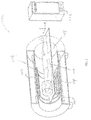
- an MRI system 100 includes a static-field magnet 102, one or more gradient-field coils 104, a radio-frequency (RF) transmitter 106, and an RF receiver (not shown). (In some embodiments, the same device is used alternately as RF transmitter or receiver.)
- the magnet includes a region 108 for receiving a patient 110 therein, and provides a static, relatively homogeneous magnetic field over the patient, which causes hydrogen nuclei spins to align with and precess about the general direction of the magnetic field.
- the spin alignment creates a net magnetization in the tissue that depends, generally, on the type of tissue and can, thus, be used to create contrast in an MR image.
- Time-variable magnetic field gradients generated by the gradient-field coils 104 are superposed with the static magnetic field so as to encode spatial information by spatio-temporally varying the precession frequency of the spins.
- the RF transmitter 106 transmits RF pulse sequences over the patient 110 to cause some of the aligned spins to alternate between a temporary high-energy non-aligned state and the aligned state, thereby inducing an RF response signal called the MR echo or MR response signal.
- the MR response signal is integrated over the entire (two- or three-dimensional) imaging region and sampled by the RF receiver to produce a time series of response signals that constitute the raw image data.
- This raw data is passed on to a computation unit 112.
- Each data point in the time series can be interpreted as the value of the Fourier transform of the position-dependent local magnetization at a particular point in k-space (i.e., wavevector space), where the wavevector k is a function of the time development of the gradient fields.
- the computation unit 112 can reconstruct a real-space image of the tissue (i.e., an image showing the measured magnetization-affecting tissue properties as a function of spatial coordinates) from the raw data.
- the real-space MR image may then be displayed to the user.
- the MRI system 100 may be used to plan a medical procedure as well as to assist in locating and guiding medical instruments and monitor treatment progress during the procedure.
- a medical procedure can be performed on a patient using a medical instrument while the patient is in the MRI machine.
- the medical instrument may be inserted into the patient, or used non-invasively, i.e., placed externally to the patient while creating a therapeutic or diagnostic effect in the tissue.
- MRI may be used to image an anatomical region of the patient, locate a treatment target within the region, monitor the location of the medical instrument (or the focus of its effects) relative to the target (preferably in real time), and/or monitor the temperature in and surrounding the target tissue.
- the medical instrument can be a focused ultrasound device 114 that is located outside a patient's body and focuses ultrasonic energy into the patient's body.
- Ultrasound penetrates well through soft tissues and, due to its short wavelengths, can be focused to spots with dimensions of a few millimeters; therefore, it can be used for highly localized non-invasive surgery - for example, to ablate, coagulate, or otherwise necrose cancerous tissue without causing significant damage to surrounding healthy tissue.
- An ultrasound focusing system generally utilizes an acoustic transducer surface, or an array of transducer surfaces, to generate an ultrasound beam.
- the transducer may be geometrically shaped and positioned such that the ultrasonic energy is focused at a "focal zone" corresponding to the target tissue mass within the patient.
- the individual surfaces, or "elements,” of the transducer array are typically individually controllable, i.e., their phases and/or amplitudes can be set independently of one another (e.g., using a "beamformer” with suitable delay and amplifier circuitry for the elements), allowing the beam to be steered in a desired direction, focused at a desired distance, and its beam profile to be conformed to a desired shape.
- the focal zone can be rapidly displaced and/or reshaped by independently adjusting the amplitudes and phases of the electrical signal input into the transducer elements; the transducer elements, in other words, are operable as a phased array.
- MR-guided focused-ultrasound (MRgFUS) treatment patient motion (such as periodic motion due to respiration or random movements) can pose a considerable challenge to therapeutic efficacy and safety. Compensation for motion is necessary to ensure that the ultrasound beam remains focused on the target and does not damage the surrounding healthy tissues.
- motion compensation is generally accomplished by tracking the target in the images and steering the ultrasound beam based on the tracked position.
- target tracking involves directly determining the coordinates of the target, or of easier identifiable "anatomical landmarks" at fixed locations relative to the target, in the images.
- the relative shifts between successive images are determined by correlating one image with a large number of computationally shifted copies of the other image, and selecting the shifted image that provides the best match.
- a library of reference images covering different stages within the anticipated range of patient motion may be acquired and analyzed prior to treatment.
- the location of the target (or other object of interest) within each reference image is stored along or in association with the respective image, e.g., in an integrated reference record.
- the images acquired in real time are correlated against the reference images in the library to determine matches based on image similarity.
- the location of the target region in the acquired treatment image is then inferred from the locational information associated with the corresponding reference image. Because image matching is, generally, computationally less involved then detecting and localizing objects within an image, this approach can achieve significant savings in processing time during treatment, thus facilitating real-time tracking.
- Motion compensation is also relevant in MR-based thermometry (i.e., the generation of temperature maps of a monitored anatomical region from MR images thereof), where it can likewise benefit from a reference library acquired prior to treatment.
- Thermometry facilitates monitoring the progress of thermal treatment of target tissue, e.g., to ensure that non-target tissues are not inadvertently heated beyond clinically tolerable levels.
- the proton resonance frequency (PRF) shift method is often optimal due to its excellent linearity with respect to temperature change, near-independence from tissue type, and temperature map acquisition with high spatial and temporal resolution.
- the PRF shift method is based on the phenomenon that the MR resonance frequency of protons in water molecules changes linearly with temperature (with a constant of proportionality that, advantageously, is relatively constant between tissue types). Since the frequency change with temperature is small, only -0.01 ppm/°C for bulk water and approximately -0.0096 to -0.013 ppm/°C in tissue, the PRF shift is typically detected with a phase-sensitive imaging method in which the imaging is performed twice: first to acquire a baseline (or reference) PRF phase image prior to a temperature change and then to acquire a second phase image - i.e., a treatment image - after the temperature change, thereby capturing a small phase change that is proportional to the change in temperature.
- a map of temperature changes may then be computed from the (reconstructed, i.e., real-space) images by determining, on a pixel-by-pixel basis, phase differences between the baseline image and the treatment image, and converting the phase differences into temperature differences based on the PRF temperature dependence while taking into account imaging parameters such as the strength of the static magnetic field and echo time (TE) (e.g., of a gradient-recalled echo). Further, if the temperature distribution in the imaged area at the time of acquisition of the baseline image is known, the temperature-difference map can be added to that baseline temperature in order to obtain the absolute-temperature distribution corresponding to the treatment image.
- TE static magnetic field and echo time
- the ability to obtain a temperature (difference) map for a treatment image depends on the existence of a suitable reference image, i.e., an image that, up to the temperature distribution, reflects the imaging conditions, including the location of the object(s) of interest, as they exist at the time the treatment image is acquired.
- a suitable reference image i.e., an image that, up to the temperature distribution, reflects the imaging conditions, including the location of the object(s) of interest, as they exist at the time the treatment image is acquired.
- a single reference (or baseline) image may suffice.
- a library of reference images covering the range of motion may be acquired prior to treatment (e.g., heating), and an absolute-temperature map may optionally be stored along with each reference image (e.g., forming a reference record including the MR image and temperature map for each stage of motion).
- a correlation or other suitable image-selection technique is performed against the library to find the baseline image best aligned, spatially, with the treatment image.
- the selected baseline image and treatment image are processed as described above to determine the changes in temperature, and an absolute-temperature map for the treatment image is computed based on the temperature map corresponding to the baseline image and the image-to-image phase changes. This method is often referred to as multi-baseline thermometry. Additional algorithms (e.g., to account for phase wrapping, to correct for drift in the static magnetic field, or to integrate measurements from multiple resources such as multiple MR channels) may also be applied.
- thermometry and object tracking for the purpose of beam steering involve very different operations and technical constraints, in both cases, the ability to accommodate movement may be critical, and may depend on the robustness of the reference library.
- the patient's movement exceeds what is anticipated (i.e., the target region in the treatment image is no longer in a region covered by the reference library and/or a baseline image is not found because the image similarities between the treatment image and reference images are insufficient)
- Movements of anatomical structures other than the target can also negate the usefulness of the reference library by disturbing the electromagnetic field (which directly affects the phase map of the image) so that the resulting treatment images do not directly correspond in detail to the reference images.
- treatment must typically be halted to allow for recalibration and realignment of the treatment device and for the acquisition and/or processing of new reference images. The result is inconvenience and delay.
- a device according to the preamble of claim 1 is known from US 2011/109309 A1 .
- the present invention relates, in various embodiments, to the use of reference libraries in image-guided treatment procedures (or other medical imaging applications), and provides systems for extending the library dynamically and, preferably, in real-time during treatment when necessary, i.e., when no suitable reference image can be found in the library for a given treatment image.
- Such reference library extension increases the flexibility of reference-based imaging and facilitates uninterrupted treatment, or at least minimizes delays, in many cases that would otherwise require the termination of a treatment procedure.
- the reference library includes a plurality of reference images (e.g., MR images) and, typically, additional application-specific data associated with each image (such as the location of an object of interest therein for motion-tracking applications, or an absolute-temperature map associated therewith for thermometry applications).
- a reference image and its associated data are collectively referred to as a "reference image record” or simply a “reference record,” regardless of whether the image and associated data are stored in an integrated data file (or multiple files) or in different data structures and/or at different memory locations (in which case an additional database may link each image with the associated information).
- the images may, e.g., be MR images, ultrasound images, X-ray images, X-Ray computer-tomography (CT) images, or other images.
- images may refer to real-space images (e.g., reconstructed MR images), the raw data from which they are derived (e.g., k-space MR images or CT projection images), or both.
- the initial reference library is generally acquired prior to treatment. Subsequently, as the anatomical region of interest is repeatedly imaged during treatment, the reference library is searched for reference images matching the series of treatment images; the treatment images and corresponding reference image records together are used to guide and/or monitor the treatment. If unanticipated movements or changes in imaging conditions are encountered during treatment and, consequently, no matching reference image is found, the treatment image (or an image derived therefrom) is incorporated into the reference library as a new reference image. Further, any additional information required to form a complete reference record for the application at hand is derived or estimated from or based on the current and/or one or more prior treatment images (optionally in combination with a physical model) and added to the reference library in association with the new reference image.
- Subsequent treatment images are then compared against the expanded reference library.
- the process is iterated, and whenever no suitable reference image is identified, the library is supplemented based on the instant treatment image, and treatment proceeds unless a termination condition imposed for safety purposes triggers early termination.
- a termination condition specifies the maximum allowable number of successive treatment images falling outside the initial reference library.
- the reference library is, thus, dynamically extended during treatment, usually obviating the need to interrupt treatment.
- a device according to the invention is defined in claim 1.
- the disclosure provides a method for monitoring an anatomical region during treatment thereof.
- a library of reference image records of the anatomical region is established; each reference image record includes a reference image and, in some embodiments, data associated with the reference image.
- treatment images of the anatomical region are repeatedly acquired.
- the reference library is extended based (at least in part) on the acquired treatment image and/or a previous treatment image by adding a new reference image record including a new reference image (which, in some embodiments, satisfies the image-similarity criterion with respect to the treatment image) to the library.
- the anatomical region is monitored based at least in part on the acquired treatment images and the reference library.
- the method further includes modifying parameters associated with the treatment (e.g., the treatment energy, the treatment power, the treatment beam shape, or the targeted area) based at least in part on the monitoring, and/or changing imaging parameters during the treatment.
- Extending the reference library may include adding the treatment image, or an image derived from the treatment image, to the library as the new reference image.
- the reference library may be extended by estimating the motion of an object of interest in the anatomical region based on at least one of the treatment image or the previous image, acquiring a new treatment image encompassing the object of interest based on the estimated motion, and adding the new treatment image to the library as the new reference image.
- Extending the reference library may further include deriving corresponding data for the new reference image and adding it to the library in association therewith.
- the library is initially empty of reference images.
- the library initially contains a plurality of reference images each corresponding to a different stage of motion of the anatomical region.
- the data associated with the different reference images includes respective locations of one or more objects of interest (e.g., a treatment target and/or non-target tissues or organs sensitive to therapeutic energy) therein.
- Monitoring the anatomical region may involve monitoring the location(s) of the object(s) of interest based on the locations stored in association with reference images matching the acquired treatment images.
- the treatment may include the application of a therapeutic energy beam to the target; based on the monitored location(s) of the target and/or sensitive organs, the beam may be adjusted.
- the location of the object of interest in a new reference image may be derived from the treatment image using image analysis. Alternatively, the location of the object of interest in the new reference image may be derived from one or more previous treatment images and a physical model characterizing motion of the object of interest.
- the data associated with the reference images includes thermal maps corresponding thereto.
- the method may involve monitoring a temperature change within the anatomical region based on phase differences between the acquired treatment images and the matching reference images; the absolute temperature within the anatomical region may be monitored based, further, on the thermal maps stored in association with the reference images matching the acquired treatment images.
- the thermal map corresponding to a new reference image may be derived from one or more thermal maps corresponding to one or more previous treatment images, optionally based, further, on a physical model (which may, e.g., characterize motion of the monitored anatomical region, or the temperature evolution within the region).
- the method may further involve establishing a thermal map of the anatomical region after treatment, and retroactively adjusting the monitored absolute temperature during treatment based thereon.
- the system according to the invention may also include an ultrasound transducer array for focusing a therapeutic energy beam onto a target in the anatomical region, and the computation unit may be configured to adjust the beam based on the monitoring.
- Each reference image record may include data associated with the reference image of the respective record, and the computation unit may be configured to derive data corresponding to the new reference image and adding it to the library in association therewith.
- the data associated with the reference images include respective locations of one or more objects of interest therein.
- the computation unit may be configured to monitor the location(s) of the object(s) of interest based on the locations stored in association with reference images matching the acquired treatment images; the treatment may be adjusted based on the monitored locations.
- the data associated with the reference images comprises thermal maps corresponding thereto.
- the computation unit may be configured to monitor an absolute temperature in the anatomical region based on phase differences between the acquired treatment images and matching reference images and on the thermal maps stored in association with the matching reference images.
- the present invention relates generally to systems for imaging an anatomical region within a patient, typically in conjunction with treatment thereof, and in particular to reference-based imaging that facilitates compensating for patient motion, changes in the treatment configuration or imaging parameters (e.g., the scan field), or other factors affecting the processing and analysis of the acquired images.
- reference-based imaging facilitates compensating for patient motion, changes in the treatment configuration or imaging parameters (e.g., the scan field), or other factors affecting the processing and analysis of the acquired images.
- the instant invention provides methods for dynamically extending the reference library during treatment if needed.
- the following description refers specifically to MR imaging applications. It should be understood, however, that the concepts and features discussed herein are applicable to other imaging modalities as well.
- the method 200 involves, prior to treatment, acquiring a plurality of reference images of an imaging region including the anatomical region of interest (step 202).
- the reference images may cover an anticipated range of motion of the anatomical region or objects and tissues therein, with each image corresponding to a different stage of motion (e.g., a different stage in a respiratory cycle).
- the reference images may be acquired under different imaging conditions and/or treatment configurations, and may, generally, correspond to different phase backgrounds resulting from various factors.
- the method further involves deriving or otherwise obtaining additional information associated with each image (step 204).
- the reference library may provide baseline images for background subtraction that cover a range of expected phase backgrounds (e.g., resulting from movements of or within the region to be monitored, or from other phase-affecting conditions that are not temperature-related), and each image may have an absolute-temperature map associated therewith.
- FIGS. 3 and 4 discussed further below, illustrate in more detail the application of the method 200 to target tracking and thermometry, respectively.
- the reference images and associated data are stored as reference records in a reference library (step 206).
- the anatomical region is repeatedly imaged (step 208), and each treatment image is compared against the reference library based on image similarity to determine whether any of the reference images matches the treatment image (step 210).
- the comparison may generally be based on real-space or k-space image data, i.e., it may involve, but does not necessarily require, the reconstruction of real-space treatment images from the raw data acquired during treatment. Further, it may suffice to compare portions of the images.
- the comparison is performed on a pixel-by-pixel basis, where a "pixel" refers to an element of the image data array, which generally stores amplitude and phase values as a function of real-space coordinates or k-space coordinates.
- Suitable similarity metrics include, for example, cross-correlation coefficients, the sum of squared intensity differences, mutual information (as the term is used in probability and information theory), ratio-image uniformity (i.e., the normalized standard deviation of the ratio of corresponding pixel values), the mean squared error, the sum of absolute differences, the sum of squared errors, the sum of absolute transformed differences (which uses a Hadamard or other frequency transform of the differences between corresponding pixels in the two images), or complex cross-correlation (for complex images, such as MRI images), and other techniques familiar, to those of skill in the art, in connection with image registration.
- cross-correlation coefficients the sum of squared intensity differences, mutual information (as the term is used in probability and information theory), ratio-image uniformity (i.e., the normalized standard deviation of the ratio of corresponding pixel values), the mean squared error, the sum of absolute differences, the sum of squared errors, the sum of absolute transformed differences (which uses a Hadamard or other frequency transform of the differences between corresponding
- the treatment image is compared against the reference library based on meta-data such as scan parameters or other external information (e.g., the state of a respiratory monitoring belt).
- meta-data such as scan parameters or other external information (e.g., the state of a respiratory monitoring belt).
- image similarity broadly connotes similarity based on any suitable metric (as described above) and/or on meta-data associated with the image.
- the determination whether a match exists is based on a specified image-similarity criterion. For example, the similarity between the treatment image and the closest reference image, as measured by the chosen similarity metric, may be compared against a (metric-specific) similarity threshold, and only if the level of similarity surpasses that of the threshold (which typically means, for metrics that measure the differences, i.e., the dissimilarity, between images, that the value of the metric falls below the threshold value) is the reference image considered a match for the treatment image. If a matching reference image is found, treatment proceeds in the conventional manner, using the treatment image and the corresponding reference image record as applicable to monitor and/or adjust the treatment (step 212) (see, e.g., FIGS. 3 and 4 ).
- the reference library is supplemented with a new reference image record (step 214).
- This extension usually involves two steps: First, a new reference image that satisfies the image-similarity criterion with respect to the treatment image is added to the library (step 216).
- the treatment image itself may be used as the new reference image; the image-similarity criterion is then trivially satisfied.
- the treatment image is further processed to yield a suitable reference image. For example, hot spots resulting from the treatment may be removed from the image so as to leave a phase background unrelated to the treatment.
- the treatment image and the new reference image will still be the same, ensuring satisfaction of the similarity criterion.
- the scan field itself may be shifted (by changing suitable imaging parameters) to re-capture the target (or other object), and a new treatment image may be acquired at the new position and added as a new reference image to the library.
- treatment images subsequently acquired at the new position are compared with the newly added reference image(s) obtained at the same position.
- the treatment images may be matched to the references based on similarity and, in some cases, meta-data such as scan parameters or other external information (e.g., the state of a respiratory monitoring belt).
- the requisite shift in the scan field may be lateral if the target has moved in-plane, or to a new imaging plane if the target has moved out-of-plane.
- application-specific data associated with the new reference image is derived based on the treatment image, one or more previously acquired treatment images, existing reference records, and/or other available information (such as a model of the target motion) (step 218) and stored along with the new reference image.
- the data associated with the new reference record may then be used, along with the treatment image to which it corresponds, to monitor and/or adjust the treatment (step 212).
- the imaging process itself is also adjusted via one or more imaging parameters (step 220), e.g., to retain the scan field around the current target position or to optimize image contrast.
- other monitoring parameters such as the frequency of image acquisition, may be adjusted, e.g., to conserve scarce computational resources by imaging at a rate commensurate with motion and other changes within the monitored region.
- the process can be repeated indefinitely, or until treatment is complete. If the treatment images deviate too much (or for too long) from the scope of the original library, however, it may be desirable to terminate the procedure prematurely for safety reasons (step 230). For example, if several successive treatment images cannot be matched against any of the reference images, requiring repeated estimates of treatment-relevant information (such as the location of the treatment target), the uncertainty associated with these estimates may increase beyond a tolerable level. Similarly, a tracked organ may move too far outside the anticipated range of motion, or imaging parameters may exceed their expected ranges by too much. Further, in some instances it may not be possible to derive the required application-specific data associated with the new reference image from the treatment image.
- the intercedently derived reference records may be revised retroactively based on the new treatment images. For example, a target location extrapolated for a non-covered treatment image from the successive locations associated with a preceding series of covered treatment images may be corrected or further refined based on a subsequent covered treatment image.
- FIG. 3 illustrates reference-library extension in the context of real-time tracking of a treatment target or other anatomical object of interest during treatment thereof.
- the treatment may involve, for example, the application of focused ultrasound to (i.e., the sonication of) a tissue or organ for the purpose of heating it, either to necrose, ablate, or otherwise destroy the tissue if it is, e.g., cancerous, or for non-destructive treatments such as pain amelioration or the controlled inducement of hyperthermia.
- Ultrasound may also be used for other, nonthermal types of treatment, such as, e.g., neuromodulation.
- the treatment may involve other treatment modalities using different forms of therapeutic energy, such as, e.g., radio-frequency (RF) radiation, X-rays or gamma rays, or charged particles.
- Motion tracking during the treatment may serve to guide the therapeutic energy beam onto the target and/or around other, non-target tissues and organs, i.e., to adjust the beam focus, profile, and/or direction based on images of the affected anatomical region.
- RF radio-frequency
- the method 300 begins with acquiring a reference library that covers different stages during an anticipated range of target motion (step 302), and processing the individual reference images to determine the location of the target therein (step 304).
- this step 304 is performed on real-space images reconstructed from the MR raw (i.e., k-space) data, using any of a variety of feature-detection or tracking methods known to those of skill in the art, including, without limitation, edge or blob detection to identify the target itself or an anatomical landmark fixedly positioned relative thereto; block-matching algorithms, phase-correlation, optical-flow methods, or other direct, pixel-based methods to determine motion vectors (or relative changes in the target or landmark locations) between different images; and/or indirect, feature-based methods for matching corresponding features between images.
- the locational information extracted from each reference image (in step 304) is stored along with the image in a reference image record (step 306).
- the anatomical region of interest including the (generally moving) target is monitored by repeatedly imaging the region (step 308), matching each treatment image, if possible, with one of the reference images in the library by applying a similarity criterion to the real-space or k-space image data (or a portion thereof) (step 310), and inferring the target location from the locational information stored with the selected reference image (step 311). Based on the target location thus determined, the beam focus can then be steered onto the target (step 312), and the process continues with the acquisition of the next treatment image (step 308).
- a predetermined threshold - the location of the target in the new image is established by other means (step 318). For example, if the target is still within the new treatment image, just not in the region of motion covered by the initial reference library, the same methods as are used to determine the target location in the reference images (in step 304) may be employed.
- the target location once computed, is stored along with the treatment image as a new reference record in the library such that, the next time the target is encountered in the same or a similar position, the treatment procedure will benefit in real-time from the previous computation.
- the target has moved outside the field of the treatment image altogether, it may be possible to derive its location from the treatment image if the anatomical region covered by the treatment image overlaps (appreciably - e.g., more than 1/3 or, in some embodiments, more than 1/2) with at least one of the reference images: using image registration based on the overlapping image portions, the relative shift and deformation of the anatomical region - and thus the target - between the treatment and reference images may be determined.
- the target movement and/or current target location may be extrapolated from one or more prior treatment images in which the target's location is known.
- such extrapolation may be aided by a physical model of target motion and/or by supplemental measurements of target location using additional equipment such as, e.g., a respiratory monitoring belt.
- the imaging field is steered to encompass the estimated location of the target (step 320), and a new treatment image is obtained (step 321).
- the location of the target is then associated with the newly obtained treatment image, and both are added to the reference library as a new reference record (step 314).
- the new reference image may, in certain embodiments, be calculated.
- the new coordinates of the target are now established, and the treatment beam can be steered accordingly (step 312).
- the newly acquired treatment image may be analyzed to determine the target boundaries and shape the focal zone accordingly (also step 312).
- FIG. 4 illustrates a method 400 for reference-library extension in the context of MR thermometry, i.e., repeated image-based measurements of the temperature distribution in an anatomical region of interest (typically for the purpose of monitoring the progress of thermal treatment).
- the reference images acquired prior to treatment serve, in this application, as baseline images that reflect a phase background independent of the temperature changes caused during the subsequent treatment; these baseline images can be subtracted from corresponding treatment images to extract the temperature-related phase contributions from the latter.
- Different reference images correspond to different phase backgrounds that can result from different locations of the treatment target itself, from different configurations of the surrounding tissues, the treatment device or other medical devices within or in the vicinity of the imaging region, and/or from other differences in imaging conditions, including a deliberate shift in the scan location (e.g., for the purpose of eliminating artifacts, switching to another target on the fly, monitoring objects of interest in the background of the target, or compensating in advance for predict motion or other events).
- anatomical constraints may require the treatment device to be moved to a series of different locations relative to the treated anatomical region (e.g., to access different targets or heat a target uniformly from different directions), and the different device locations may affect the image phase background.
- different treatment stages may require different reference images for proper phase background subtraction.
- the reference images facilitate computing a map of temperature changes relative to a baseline temperature distribution as it existed at the acquisition time of a references image.
- this baseline temperature distribution may be established for each reference image (step 404) and stored along with the image (step 406).
- Establishing the baseline temperature may involve, e.g., a simple assumption or a mathematical fit to temperatures directly measured at one or more discrete locations.
- the anatomical region of interest has, prior to treatment, a uniform temperature, e.g., body temperature (37 °C), which constitutes the baseline temperature.
- active cooling or heating
- tissue surfaces establishing a temperature gradient across the region of interest that can be estimated based on direct temperature measurements at a few selected points.
- thermal treatment commences. For example, ultrasound may be focused at a target to locally heat the target tissue. In general, the absorbed heat will dissipate into surrounding tissues and increase their temperature at least slightly.
- the temperature changes within a region encompassing the target can be monitored by imaging the region (step 408), comparing the image against the reference library (step 410) in order to identify a well-registered reference image based on an image-similarity criterion, and processing the matching reference and treatment images to determine a temperature-difference map (step 412).
- thermometry typically involves the pixel-wise subtraction of complete real-space images (and subsequent conversion of the phase difference into a temperature-difference map).
- the absolute-temperature map stored along with the selected reference image i.e., as part of the selected reference image record
- the "hot spot" generated by the treatment is typically disregarded; for example, the heated region may be masked in the images such that the similarity measurements is based solely on the surrounding area (whose temperature is, ideally, stable).
- the reference images acquired prior to treatment are deliberately manipulated to reflect the expected temperature increase in the target; in other words, a "fake” phase map is created that is as similar as possible to the treatment image.
- a suitable reference for the treatment image can be identified without the need to mask or otherwise compensate for the hot spot.
- a new reference record is added to the library (step 414) based on the instant treatment image (or, if the target has moved outside the image, a new treatment image obtained after the scan field has been shifted to encompass the target, as depicted in FIG. 3 ), which may be added as is as a new reference image (step 416), and a corresponding temperature distribution that may be computed or estimated from a previous temperature map (or multiple prior temperature maps) using a physical model (step 418).
- the previous temperature map may be, e.g., the temperature distribution determined from the last treatment image for which a suitable reference image was found or, alternatively, the most recently obtained temperature map, whether it was measured or, itself, computed and/or estimated.
- the physical model may account for both movement and deformation of the mapped anatomical region (if any) and the temperature evolution in the region since the point in time associated with the previous temperature map, and may be based on theoretical information as well as on treatment images or other measurements taken since the beginning of the treatment procedure.
- changes in the location and/or spatial confirmation of the target and surrounding tissues can often be determined from the current treatment image and a previous (e.g., the most recent) treatment image, optionally in conjunction with a physical model that accounts for tissue elasticity and movement constraints.
- the temperature map associated with the former may be translated, extrapolated, and/or deformed, by methods known to those of skill in the art, to yield a new temperature map that compensates for the motion and/or deformation.
- the new thermal map may be "sliced" from a volumetric temperature map estimated from one or more previous temperature maps (e.g., by interpolation between temperature maps corresponding to treatment images simultaneously acquired in imaging planes that bracket the current imaging plane).
- the previous temperature map (or a new temperature map derived therefrom to account for tissue movement and deformation) is adjusted to reflect the temperature evolution in the imaged region.
- changes in temperature resulting from the deliberate application of thermal energy can be computed or estimated based on known treatment parameters (e.g., the intensity and duration of, or the total energy delivered during, a sonication) in conjunction with a model of energy absorption and transport in the tissue.
- known treatment parameters e.g., the intensity and duration of, or the total energy delivered during, a sonication
- models for temperature evolution may be volumetric, and may use multiple previous temperature maps measured concurrently or sequentially in different imaging planes as input.
- temperature measurements may repeatedly cycle through multiple imaging planes.
- the evolution of the temperature in a monitored region may be modeled based on temperature measurements (e.g., multiple previous temperature maps) acquired at different times in the past.
- the physical model, as applied to the previously obtained temperature map(s) may provide a pixel-by-pixel estimate of the current temperature.
- the new estimated temperature map is associated with the current treatment image (which serves as a new reference image) in the reference library.
- a temperature map for a subsequent treatment image that satisfies the similarity criterion with respect to the new reference image may be generated from the phase differences between the images and the saved temperature map associated with the new reference image.
- the new reference image is derived from the treatment image by subtracting out the hot spot in order to obtain a new reference image resembling those acquired prior to treatment.
- the hot spot is, in this case, also removed from the estimated temperature map stored along with the new reference image.
- the treatment may be adjusted (step 424). For example, if the temperature in the region surrounding the target approaches intolerably high levels, the energy applied in subsequent sonications (or other treatment steps) may be reduced.
- image acquisition continues until the temperature in the monitored area has returned to a known temperature distribution, e.g., body temperature.
- a known temperature distribution e.g., body temperature.
- retroactive temperature monitoring can be useful to verify the temperatures measured during treatment and/or alert the treating physician or other system operator to any errors and unexpected events.
- the methods described above can be modified in several ways. For example, various method steps may be executed in a different order than described. Moreover, in some embodiments, the steps of acquiring an initial reference library prior to treatment are omitted, and the library is, instead, compiled during treatment by successively adding reference records comprising treatment images (or images derived therefrom) and associated data to the library, beginning with an initially empty library. Further, target tracking and thermometry (e.g., as described above with reference to FIGS. 3 and 4 ) may be combined in various ways and configurations, e.g., using separate, shared, or partially shared libraries and employing the same or separate image similarity criteria.
- each reference record may include a reference/baseline image and, associated therewith, target coordinates and a thermal map.
- Reference-library extension (e.g., as more generally described with reference to FIG. 2 ) may also be applied to other imaging methods that utilize a previously compiled reference library during a real-time procedure.
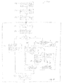
- FIG. 5 illustrates an exemplary embodiment where the facility is provided by a suitably programmed general-purpose computer 500.
- the computer includes a central processing unit (CPU) 502, system memory 504, and nonvolatile mass storage devices 506 (such as, e.g., one or more hard disks and/or optical storage units).
- the computer 500 further includes a bidirectional system bus 508 over which the CPU 502, memory 504, and storage devices 506 communicate with each other and with internal or external input/output devices, such as traditional user interface components 510 (including, e.g., a screen, a keyboard, and a mouse) as well as the treatment apparatus 512, the imaging apparatus 514, and (optionally) any temperature sensors 516 facilitating absolute-temperature measurements.
- traditional user interface components 510 including, e.g., a screen, a keyboard, and a mouse
- any temperature sensors 516 facilitating absolute-temperature measurements.
- the system memory 504 may store the reference library 518.
- the library may be stored on the mass storage devices 506, and individual reference records may be loaded into system memory 504 as needed.
- each reference record is a data file storing both the (raw and/or real-space) image data and the (application-specific) associated data (such as the target coordinates or an absolute-temperature map).
- the reference record may consist of multiple files, which, however, form an integrated data structure; for example, the record may include a file storing the associated data along with a pointer to the corresponding image file.
- the library 518 is stored in the form of a plurality of image files, a plurality of application-specific data files (e.g., thermal maps), and a database linking the images with the corresponding associated information.
- the system memory 504 further stores instructions, conceptually illustrated as a group of modules, that control the operation of CPU 502 and its interaction with the other hardware components.
- An operating system 520 directs the execution of low-level, basic system functions such as memory allocation, file management and operation of mass storage devices 506.
- one or more service applications provide the computational functionality required for image-processing, the particular imaging application(s) (e.g., motion tracking and/or thermometry), and creation and extension of the reference library 518.
- the system may include an image processing module 522 for reconstructing real-space images from raw image data received from the imaging apparatus 514 and performing other general image-processing functions; an image analysis module 524 for extracting locational information of the target and/or other object(s) of interest from the reconstructed reference images; a thermometry module 526 for computing temperature-difference and absolute-temperature maps from the treatment images and the information in the reference library; a physical-modeling module 528 for computationally simulating motion, deformation, and/or temperature evolution in the anatomical region of interest; a treatment-control module 530 for computing and adjusting treatment parameters (such as the desired beam direction and intensity) and controlling the treatment apparatus 512 based thereon (e.g., via computed relative phases between the elements of a phased-array ultrasound transducer); an image-control module 532 for controlling the imaging apparatus 514; and a reference-managing module 534 for measuring similarity between treatment and reference images (whether raw or reconstructed images) and selecting suitable reference images
- modules may be programmed in any suitable programming language, including, without limitation, high-level languages such as C, C++, C#, Ada, Basic, Cobra, Fortran, Java, Lisp, Perl, Python, Ruby, or Object Pascal, or low-level assembly languages; in some embodiments, different modules are programmed in different languages.
Landscapes
- Engineering & Computer Science (AREA)
- Health & Medical Sciences (AREA)
- Life Sciences & Earth Sciences (AREA)
- Physics & Mathematics (AREA)
- Nuclear Medicine, Radiotherapy & Molecular Imaging (AREA)
- Radiology & Medical Imaging (AREA)
- General Health & Medical Sciences (AREA)
- Biomedical Technology (AREA)
- Veterinary Medicine (AREA)
- Public Health (AREA)
- Animal Behavior & Ethology (AREA)
- Theoretical Computer Science (AREA)
- General Physics & Mathematics (AREA)
- Computer Vision & Pattern Recognition (AREA)
- Multimedia (AREA)
- Biophysics (AREA)
- Surgery (AREA)
- Molecular Biology (AREA)
- Medical Informatics (AREA)
- Heart & Thoracic Surgery (AREA)
- Pathology (AREA)
- High Energy & Nuclear Physics (AREA)
- Magnetic Resonance Imaging Apparatus (AREA)
- Surgical Instruments (AREA)
- Ultra Sonic Daignosis Equipment (AREA)
- Radiation-Therapy Devices (AREA)
- Apparatus For Radiation Diagnosis (AREA)
Claims (14)
- Un système pour le contrôle d'une région anatomique au cours du traitement de celle-ci, le système étant composé :(a) d'un appareil d'imagerie pour l'imagerie de la région anatomique ;(b) d'une mémoire pour le stockage de dossiers d'images de référence composés d'images de référence de la région anatomique et de données relatives aux images de référence, y compris au moins un des emplacements respectifs d'un ou plusieurs objets d'intérêt ou cartes thermiques correspondant à l'image de référence ; et(c) une unité de calcul configurée pour (i) déterminer de façon répétée l'acquisition par l'appareil d'imagerie d'une image du traitement de la région anatomique au cours du traitement, (ii) comparer l'image de traitement acquise avec les images de référence dans la bibliothèque, sur la base de données d'image en espace réel ou en espace K, afin d'établir si des images de référence dans la bibliothèque correspondent à l'image de traitement acquise, selon un critère de similarité d'image, caractérisée en ce que l'unité de calcul est également configurée, (iii) si aucune des images de référence dans la bibliothèque ne correspond à l'image de traitement acquise, pour enrichir la bibliothèque de référence sur la base, du moins en partie, d'au moins une des suivantes : l'image de traitement acquise ou une image de traitement précédente, en ajoutant un nouveau dossier d'image de référence, composé d'une nouvelle image de référence et de données associées avec la nouvelle référence d'images, y compris au moins un d'un nouveaux emplacements correspondants du ou de plusieurs objets d'intérêt, ou une nouvelle carte thermique leur correspondant dans la bibliothèque, (iv) contrôler la région anatomique sur la base, du moins en partie, des images de traitement acquises et de la bibliothèque de référence renforcée, et (v) répéter les opérations (i) - (iv) jusqu'à ce qu'un nombre admissible maximum d'images de traitement successives débordent du cadre de la bibliothèque de référence stockée initialement au point (b).
- Le système selon la revendication 1, comprenant également une matrice de transducteurs ultrasonores pour concentrer un faisceau d'énergie thérapeutique sur un objectif dans la région anatomique.
- Le système selon la revendication 2, l'unité de calcul étant configurée pour ajuster le faisceau en fonction du contrôle.
- Le système selon la revendication 1, le renforcement de la bibliothèque comprenant l'estimation du mouvement d'un objet d'intérêt dans la région anatomique de l'image du traitement ou de l'image précédente, et d'une des deux, la saisie d'une nouvelle image du traitement comprenant l'objet d'intérêt sur la base du mouvement estimé, et l'adjonction de la nouvelle image de traitement dans la bibliothèque, à titre de nouvelle image de référence.
- Le système selon la revendication 1, chaque dossier d'image de référence comprenant également des données associées avec l'image de référence du dossier correspondant, l'unité de calcul étant configurée pour dériver des données correspondant à la nouvelle image de référence, et les ajouter à la bibliothèque en association avec celle-ci.
- Le système selon la revendication 5, les données associées avec les images de référence comprenant des emplacements respectifs d'au moins un objet d'intérêt dans celles-ci.
- Le système selon la revendication 6, le système étant configuré pour dériver l'emplacement de l'objet d'intérêt dans la nouvelle image de référence, d'après au moins une image de traitement précédente, et un modèle physique caractérisant le mouvement de l'objet d'intérêt.
- Le système selon la revendication 6, le système étant configuré pour dériver l'emplacement de l'objet d'intérêt dans la nouvelle image de référence, d'après l'image de traitement en utilisant l'analyse de l'image.
- Le système selon la revendication 5, les données associées avec les images de référence comprenant des emplacements respectifs de multiples objets d'intérêt dans celles-ci, le contrôle de la région anatomique comprenant le contrôle d'emplacements des objets d'intérêt en fonction des emplacements stockés en association avec des images de référence correspondant aux images de traitement acquises.
- Le système selon la revendication 5, l'unité de calcul étant configurée pour contrôler un emplacement de l'objet d'intérêt au nombre d'au moins un en fonction des emplacements stockés en association avec des images de référence correspondant aux images de traitement acquises.
- Le système selon la revendication 10, l'unité de calcul étant configurée pour contrôler une température absolue dans la région anatomique, en fonction d'une part des différences de phase entre les images de traitement acquises et les images de référence correspondantes, d'autre part des cartes thermique stockées en association avec les images de référence correspondantes.
- Le système selon la revendication 1, les données associées avec les images de référence comprenant des cartes thermiques correspondant à celles-ci.
- Le système selon la revendication 12, le système étant configuré pour dériver la carte thermique correspondant à la nouvelle image de référence à partir d'au moins une carte thermique correspondant à une image de traitement précédente.
- Le système selon la revendication 13, le système étant également configuré pour dériver la carte thermique correspondant à la nouvelle image de référence sur la base d'un modèle physique.
Applications Claiming Priority (3)
| Application Number | Priority Date | Filing Date | Title |
|---|---|---|---|
| US201261595341P | 2012-02-06 | 2012-02-06 | |
| US201261595338P | 2012-02-06 | 2012-02-06 | |
| PCT/IB2013/000345 WO2013117992A1 (fr) | 2012-02-06 | 2013-02-06 | Extension d'une bibliothèque de référence pendant la mise en image d'organes en mouvement |
Publications (2)
| Publication Number | Publication Date |
|---|---|
| EP2811901A1 EP2811901A1 (fr) | 2014-12-17 |
| EP2811901B1 true EP2811901B1 (fr) | 2016-06-08 |
Family
ID=48143323
Family Applications (2)
| Application Number | Title | Priority Date | Filing Date |
|---|---|---|---|
| EP13717849.7A Active EP2811900B1 (fr) | 2012-02-06 | 2013-02-06 | Suivi de mouvement à partir d'une référence pendant un traitement non-invasif |
| EP13717851.3A Active EP2811901B1 (fr) | 2012-02-06 | 2013-02-06 | Extension d'une bibliothèque de référence pendant la mise en image d'organes en mouvement |
Family Applications Before (1)
| Application Number | Title | Priority Date | Filing Date |
|---|---|---|---|
| EP13717849.7A Active EP2811900B1 (fr) | 2012-02-06 | 2013-02-06 | Suivi de mouvement à partir d'une référence pendant un traitement non-invasif |
Country Status (5)
| Country | Link |
|---|---|
| US (2) | US9814909B2 (fr) |
| EP (2) | EP2811900B1 (fr) |
| JP (2) | JP6249491B2 (fr) |
| CN (2) | CN104219996B (fr) |
| WO (2) | WO2013117991A1 (fr) |
Cited By (1)
| Publication number | Priority date | Publication date | Assignee | Title |
|---|---|---|---|---|
| WO2020109860A1 (fr) * | 2018-11-28 | 2020-06-04 | Insightec, Ltd. | Systèmes et procédés de correction d'artefacts de mesure de thermométrie par résonance magnétique |
Families Citing this family (33)
| Publication number | Priority date | Publication date | Assignee | Title |
|---|---|---|---|---|
| US8256430B2 (en) | 2001-06-15 | 2012-09-04 | Monteris Medical, Inc. | Hyperthermia treatment and probe therefor |
| WO2014003855A1 (fr) | 2012-06-27 | 2014-01-03 | Monteris Medical Corporation | Thérapie guidée par image d'un tissu |
| DE102012216292B4 (de) * | 2012-09-13 | 2021-02-18 | Siemens Healthcare Gmbh | Magnetresonanzbaueinheit, eine Magnetresonanzvorrichtung mit der Magnetresonanzbaueinheit sowie ein Verfahren zu einem Bestimmen einer Bewegung eines Patienten während einer Magnetresonanzuntersuchung |
| US9649508B2 (en) | 2012-09-13 | 2017-05-16 | Emory University | Methods, systems and computer readable storage media storing instructions for determining patient specific treatment planning margins |
| US9672187B2 (en) * | 2013-03-15 | 2017-06-06 | Electric Power Research Institute | System and method for directing guided waves through structures |
| US9715726B2 (en) * | 2013-12-05 | 2017-07-25 | Siemens Healthcare Gmbh | Method and system for B0 drift and respiratory motion compensation in echo-planar based magnetic resonance imaging |
| CN106233322A (zh) * | 2014-03-03 | 2016-12-14 | 赛曼提克姆德公司 | 基于个性化内容的患者检索系统 |
| WO2015143026A1 (fr) | 2014-03-18 | 2015-09-24 | Monteris Medical Corporation | Thérapie guidée par l'image d'un tissu |
| WO2015143025A1 (fr) | 2014-03-18 | 2015-09-24 | Monteris Medical Corporation | Thérapie guidée par l'image d'un tissu |
| US10675113B2 (en) | 2014-03-18 | 2020-06-09 | Monteris Medical Corporation | Automated therapy of a three-dimensional tissue region |
| US10405773B2 (en) * | 2014-12-19 | 2019-09-10 | General Electric Company | Tissue delineation and characterization in magnetic resonance imaging |
| CN104587612A (zh) * | 2015-01-10 | 2015-05-06 | 管勇 | 超声颅内肿瘤治疗仪 |
| US9542761B2 (en) * | 2015-02-25 | 2017-01-10 | Siemens Healthcare Gmbh | Generalized approximate message passing algorithms for sparse magnetic resonance imaging reconstruction |
| US10327830B2 (en) | 2015-04-01 | 2019-06-25 | Monteris Medical Corporation | Cryotherapy, thermal therapy, temperature modulation therapy, and probe apparatus therefor |
| US10537253B2 (en) * | 2016-02-25 | 2020-01-21 | Samsung Electronics Company, Ltd. | Detecting live tissues using signal analysis |
| US10475192B2 (en) * | 2016-06-10 | 2019-11-12 | Insightec, Ltd. | Motion tracking during non-invasive therapy |
| US11284811B2 (en) * | 2016-06-22 | 2022-03-29 | Viewray Technologies, Inc. | Magnetic resonance volumetric imaging |
| JP7098539B2 (ja) | 2016-06-22 | 2022-07-11 | ビューレイ・テクノロジーズ・インコーポレイテッド | 磁気共鳴イメージング |
| EP3482390B1 (fr) * | 2016-07-08 | 2021-09-08 | Insightec Ltd. | Systèmes et procédés pour assurer la cohérence entre des réseaux de transducteurs à ultrasons multiples |
| US11103731B2 (en) * | 2017-01-12 | 2021-08-31 | Insightec, Ltd. | Overcoming acoustic field and skull non-uniformities |
| CN110392546B (zh) | 2017-03-07 | 2022-09-02 | 索尼公司 | 信息处理设备、辅助系统和信息处理方法 |
| US20210093897A1 (en) * | 2017-10-05 | 2021-04-01 | Insighitec, Ltd | Frameless ultrasound therapy |
| JP6976869B2 (ja) | 2018-01-15 | 2021-12-08 | キヤノンメディカルシステムズ株式会社 | 超音波診断装置及びその制御プログラム |
| US20190351261A1 (en) * | 2018-05-18 | 2019-11-21 | Yoav Levy | Selective resampling during non-invasive therapy |
| IL263097B2 (en) * | 2018-11-18 | 2024-01-01 | Inspekto A M V Ltd | Optimization of the preparation phase in the automatic visual inspection process |
| CN109784379B (zh) * | 2018-12-27 | 2021-03-30 | 广州华迅网络科技有限公司 | 纺织品图片特征库的更新方法和装置 |
| US11684807B2 (en) * | 2018-12-27 | 2023-06-27 | Insightec Ltd. | Optimization of transducer configurations in ultrasound procedures |
| JP7171948B2 (ja) * | 2019-05-17 | 2022-11-15 | コーニンクレッカ フィリップス エヌ ヴェ | 対象の移動を追跡するための超音波システム及び方法 |
| EP3757940A1 (fr) | 2019-06-26 | 2020-12-30 | Siemens Healthcare GmbH | Détermination d'un mouvement de patient lors d'une mesure d'imagerie médicale |
| WO2021046699A1 (fr) * | 2019-09-10 | 2021-03-18 | Beijing Voyager Technology Co., Ltd. | Systèmes et procédés de positionnement |
| CN112365971B (zh) * | 2020-11-09 | 2021-06-11 | 罗鑫龙 | 一种基于5g的远程互联网大数据智慧医疗系统 |
| US11995849B2 (en) * | 2021-05-24 | 2024-05-28 | Biosense Webster (Israel) Ltd. | Automatic registration of an anatomical map to a previous anatomical map |
| US11493583B1 (en) * | 2021-11-03 | 2022-11-08 | Siemens Healthcare Gmbh | Image-based retrospective gating of MR images for PRF thermometry |
Citations (1)
| Publication number | Priority date | Publication date | Assignee | Title |
|---|---|---|---|---|
| US20110109309A1 (en) * | 2009-11-10 | 2011-05-12 | Insightec Ltd. | Techniques for correcting measurement artifacts in magnetic resonance thermometry |
Family Cites Families (27)
| Publication number | Priority date | Publication date | Assignee | Title |
|---|---|---|---|---|
| JPH0747079A (ja) * | 1993-08-05 | 1995-02-21 | Toshiba Corp | 超音波治療装置 |
| JPH07303656A (ja) * | 1994-05-12 | 1995-11-21 | Toshiba Corp | 結石破砕装置 |
| DE19515748A1 (de) * | 1995-04-28 | 1996-10-31 | Siemens Ag | Gerät zur Behandlung mit akustischen Wellen |
| US7158610B2 (en) | 2003-09-05 | 2007-01-02 | Varian Medical Systems Technologies, Inc. | Systems and methods for processing x-ray images |
| GB0109892D0 (en) * | 2001-04-20 | 2001-06-13 | Secr Defence | Method and apparatus for reducing the effects of motion in an image |
| US7046823B2 (en) * | 2002-08-01 | 2006-05-16 | Raytheon Company | Correlation tracker breaklock detection |
| JP4127640B2 (ja) * | 2002-09-19 | 2008-07-30 | 株式会社東芝 | 超音波治療装置 |
| US6928142B2 (en) * | 2002-10-18 | 2005-08-09 | Koninklijke Philips Electronics N.V. | Non-invasive plaque detection using combined nuclear medicine and x-ray system |
| US7853308B2 (en) * | 2004-02-17 | 2010-12-14 | Siemens Medical Solutions Usa, Inc. | System and method for patient positioning for radiotherapy in the presence of respiratory motion |
| US20050215904A1 (en) * | 2004-03-23 | 2005-09-29 | Siemens Medical Solutions Usa, Inc. | Ultrasound breathing waveform detection system and method |
| US8801701B2 (en) * | 2005-03-09 | 2014-08-12 | Sunnybrook Health Sciences Centre | Method and apparatus for obtaining quantitative temperature measurements in prostate and other tissue undergoing thermal therapy treatment |
| JP5047960B2 (ja) * | 2005-07-08 | 2012-10-10 | ウイスコンシン アラムナイ リサーチ ファウンデーシヨン | 高度に限定されたイメージの再構成法 |
| FR2891153B1 (fr) * | 2005-09-28 | 2008-08-22 | Centre Nat Rech Scient | Dispositif de traitement thermique de tissus biologiques en mouvement |
| JP5081251B2 (ja) * | 2006-12-08 | 2012-11-28 | コーニンクレッカ フィリップス エレクトロニクス エヌ ヴィ | 結合された治療を計画するシステム、方法、コンピュータ読み取り可能な記録媒体及び使用 |
| US8478380B2 (en) * | 2007-05-04 | 2013-07-02 | Wisconsin Alumni Research Foundation | Magnetic resonance thermometry in the presence of water and fat |
| CN101053531A (zh) * | 2007-05-17 | 2007-10-17 | 上海交通大学 | 基于多模式增敏成像融合的早期肿瘤定位跟踪方法 |
| WO2008151202A2 (fr) * | 2007-06-03 | 2008-12-11 | The Regents Of The University Of California | Cœur déformable élastique et fantôme de torse pour imagerie nucléaire du cœur avec modèles réalistes du mouvement cardiaque et respiratoire |
| US8251908B2 (en) * | 2007-10-01 | 2012-08-28 | Insightec Ltd. | Motion compensated image-guided focused ultrasound therapy system |
| US20100061596A1 (en) | 2008-09-05 | 2010-03-11 | Varian Medical Systems Technologies, Inc. | Video-Based Breathing Monitoring Without Fiducial Tracking |
| US8396248B2 (en) * | 2008-09-16 | 2013-03-12 | Varian Medical Systems, Inc. | Sequential stereo imaging for estimating trajectory and monitoring target position |
| JP5476534B2 (ja) * | 2008-09-17 | 2014-04-23 | 公益財団法人ヒューマンサイエンス振興財団 | 超音波画像処理による集束超音波自動照射システム並びに集束超音波自動照射プログラム及びこれを記録したコンピュータ読み取り可能な記録媒体 |
| US8715186B2 (en) * | 2009-11-24 | 2014-05-06 | Guided Therapy Systems, Llc | Methods and systems for generating thermal bubbles for improved ultrasound imaging and therapy |
| US8379947B2 (en) * | 2010-05-28 | 2013-02-19 | International Business Machines Corporation | Spatio-temporal image reconstruction using sparse regression and secondary information |
| US9254112B2 (en) * | 2011-03-23 | 2016-02-09 | Siemens Corporation | Respiratory interval-based correlation and processing of dynamic imaging data |
| US9028470B2 (en) * | 2011-06-17 | 2015-05-12 | University Of Utah Research Foundation | Image-guided renal nerve ablation |
| CN105105775B (zh) * | 2011-07-19 | 2018-11-09 | 东芝医疗系统株式会社 | 心肌运动解析装置 |
| DE102012216327B4 (de) * | 2012-09-13 | 2021-01-14 | Siemens Healthcare Gmbh | Verfahren zur Erfassung einer Bewegung eines Patienten während einer medizinischen Bildgebungsuntersuchung |
-
2013
- 2013-02-06 CN CN201380016281.3A patent/CN104219996B/zh active Active
- 2013-02-06 CN CN201380015282.6A patent/CN104244818B/zh active Active
- 2013-02-06 JP JP2014555335A patent/JP6249491B2/ja active Active
- 2013-02-06 WO PCT/IB2013/000321 patent/WO2013117991A1/fr active Application Filing
- 2013-02-06 JP JP2014555333A patent/JP6138162B2/ja active Active
- 2013-02-06 US US14/377,062 patent/US9814909B2/en active Active
- 2013-02-06 US US14/377,063 patent/US10307619B2/en active Active
- 2013-02-06 EP EP13717849.7A patent/EP2811900B1/fr active Active
- 2013-02-06 WO PCT/IB2013/000345 patent/WO2013117992A1/fr active Application Filing
- 2013-02-06 EP EP13717851.3A patent/EP2811901B1/fr active Active
Patent Citations (1)
| Publication number | Priority date | Publication date | Assignee | Title |
|---|---|---|---|---|
| US20110109309A1 (en) * | 2009-11-10 | 2011-05-12 | Insightec Ltd. | Techniques for correcting measurement artifacts in magnetic resonance thermometry |
Cited By (1)
| Publication number | Priority date | Publication date | Assignee | Title |
|---|---|---|---|---|
| WO2020109860A1 (fr) * | 2018-11-28 | 2020-06-04 | Insightec, Ltd. | Systèmes et procédés de correction d'artefacts de mesure de thermométrie par résonance magnétique |
Also Published As
| Publication number | Publication date |
|---|---|
| JP6138162B2 (ja) | 2017-05-31 |
| EP2811900B1 (fr) | 2017-03-29 |
| WO2013117992A1 (fr) | 2013-08-15 |
| CN104219996B (zh) | 2017-04-05 |
| EP2811900A1 (fr) | 2014-12-17 |
| CN104244818A (zh) | 2014-12-24 |
| JP2015511139A (ja) | 2015-04-16 |
| JP2015507951A (ja) | 2015-03-16 |
| US20150025360A1 (en) | 2015-01-22 |
| CN104244818B (zh) | 2017-04-12 |
| WO2013117991A1 (fr) | 2013-08-15 |
| CN104219996A (zh) | 2014-12-17 |
| US9814909B2 (en) | 2017-11-14 |
| JP6249491B2 (ja) | 2017-12-20 |
| US10307619B2 (en) | 2019-06-04 |
| EP2811901A1 (fr) | 2014-12-17 |
| US20150016682A1 (en) | 2015-01-15 |
Similar Documents
| Publication | Publication Date | Title |
|---|---|---|
| EP2811901B1 (fr) | Extension d'une bibliothèque de référence pendant la mise en image d'organes en mouvement | |
| EP3469390B1 (fr) | Suivi de mouvement pendant une thérapie non invasive | |
| US8810246B2 (en) | Hybrid referenceless and multibaseline PRF-shift magnetic resonance thermometry | |
| Preiswerk et al. | Model-guided respiratory organ motion prediction of the liver from 2D ultrasound | |
| US9541621B2 (en) | Techniques for correcting measurement artifacts in magnetic resonance thermometry | |
| US11921182B2 (en) | Accelerated magnetic resonance thermometry | |
| US20190351261A1 (en) | Selective resampling during non-invasive therapy | |
| EP4037764A1 (fr) | Procédé de filtrage de pixels erronés dans un système de commande de thérapie thermique |
Legal Events
| Date | Code | Title | Description |
|---|---|---|---|
| PUAI | Public reference made under article 153(3) epc to a published international application that has entered the european phase |
Free format text: ORIGINAL CODE: 0009012 |
|
| 17P | Request for examination filed |
Effective date: 20140903 |
|
| AK | Designated contracting states |
Kind code of ref document: A1 Designated state(s): AL AT BE BG CH CY CZ DE DK EE ES FI FR GB GR HR HU IE IS IT LI LT LU LV MC MK MT NL NO PL PT RO RS SE SI SK SM TR |
|
| AX | Request for extension of the european patent |
Extension state: BA ME |
|
| DAX | Request for extension of the european patent (deleted) | ||
| 17Q | First examination report despatched |
Effective date: 20150601 |
|
| GRAP | Despatch of communication of intention to grant a patent |
Free format text: ORIGINAL CODE: EPIDOSNIGR1 |
|
| INTG | Intention to grant announced |
Effective date: 20160202 |
|
| GRAS | Grant fee paid |
Free format text: ORIGINAL CODE: EPIDOSNIGR3 |
|
| GRAA | (expected) grant |
Free format text: ORIGINAL CODE: 0009210 |
|
| AK | Designated contracting states |
Kind code of ref document: B1 Designated state(s): AL AT BE BG CH CY CZ DE DK EE ES FI FR GB GR HR HU IE IS IT LI LT LU LV MC MK MT NL NO PL PT RO RS SE SI SK SM TR |
|
| REG | Reference to a national code |
Ref country code: GB Ref legal event code: FG4D |
|
| REG | Reference to a national code |
Ref country code: CH Ref legal event code: EP |
|
| REG | Reference to a national code |
Ref country code: IE Ref legal event code: FG4D |
|
| REG | Reference to a national code |
Ref country code: AT Ref legal event code: REF Ref document number: 804635 Country of ref document: AT Kind code of ref document: T Effective date: 20160715 |
|
| REG | Reference to a national code |
Ref country code: DE Ref legal event code: R096 Ref document number: 602013008396 Country of ref document: DE |
|
| REG | Reference to a national code |
Ref country code: LT Ref legal event code: MG4D |
|
| REG | Reference to a national code |
Ref country code: NL Ref legal event code: MP Effective date: 20160608 |
|
| PG25 | Lapsed in a contracting state [announced via postgrant information from national office to epo] |
Ref country code: FI Free format text: LAPSE BECAUSE OF FAILURE TO SUBMIT A TRANSLATION OF THE DESCRIPTION OR TO PAY THE FEE WITHIN THE PRESCRIBED TIME-LIMIT Effective date: 20160608 Ref country code: LT Free format text: LAPSE BECAUSE OF FAILURE TO SUBMIT A TRANSLATION OF THE DESCRIPTION OR TO PAY THE FEE WITHIN THE PRESCRIBED TIME-LIMIT Effective date: 20160608 Ref country code: NO Free format text: LAPSE BECAUSE OF FAILURE TO SUBMIT A TRANSLATION OF THE DESCRIPTION OR TO PAY THE FEE WITHIN THE PRESCRIBED TIME-LIMIT Effective date: 20160908 |
|
| REG | Reference to a national code |
Ref country code: AT Ref legal event code: MK05 Ref document number: 804635 Country of ref document: AT Kind code of ref document: T Effective date: 20160608 |
|
| PG25 | Lapsed in a contracting state [announced via postgrant information from national office to epo] |
Ref country code: RS Free format text: LAPSE BECAUSE OF FAILURE TO SUBMIT A TRANSLATION OF THE DESCRIPTION OR TO PAY THE FEE WITHIN THE PRESCRIBED TIME-LIMIT Effective date: 20160608 Ref country code: ES Free format text: LAPSE BECAUSE OF FAILURE TO SUBMIT A TRANSLATION OF THE DESCRIPTION OR TO PAY THE FEE WITHIN THE PRESCRIBED TIME-LIMIT Effective date: 20160608 Ref country code: SE Free format text: LAPSE BECAUSE OF FAILURE TO SUBMIT A TRANSLATION OF THE DESCRIPTION OR TO PAY THE FEE WITHIN THE PRESCRIBED TIME-LIMIT Effective date: 20160608 Ref country code: GR Free format text: LAPSE BECAUSE OF FAILURE TO SUBMIT A TRANSLATION OF THE DESCRIPTION OR TO PAY THE FEE WITHIN THE PRESCRIBED TIME-LIMIT Effective date: 20160909 Ref country code: HR Free format text: LAPSE BECAUSE OF FAILURE TO SUBMIT A TRANSLATION OF THE DESCRIPTION OR TO PAY THE FEE WITHIN THE PRESCRIBED TIME-LIMIT Effective date: 20160608 Ref country code: NL Free format text: LAPSE BECAUSE OF FAILURE TO SUBMIT A TRANSLATION OF THE DESCRIPTION OR TO PAY THE FEE WITHIN THE PRESCRIBED TIME-LIMIT Effective date: 20160608 Ref country code: LV Free format text: LAPSE BECAUSE OF FAILURE TO SUBMIT A TRANSLATION OF THE DESCRIPTION OR TO PAY THE FEE WITHIN THE PRESCRIBED TIME-LIMIT Effective date: 20160608 |
|
| PG25 | Lapsed in a contracting state [announced via postgrant information from national office to epo] |
Ref country code: CZ Free format text: LAPSE BECAUSE OF FAILURE TO SUBMIT A TRANSLATION OF THE DESCRIPTION OR TO PAY THE FEE WITHIN THE PRESCRIBED TIME-LIMIT Effective date: 20160608 Ref country code: RO Free format text: LAPSE BECAUSE OF FAILURE TO SUBMIT A TRANSLATION OF THE DESCRIPTION OR TO PAY THE FEE WITHIN THE PRESCRIBED TIME-LIMIT Effective date: 20160608 Ref country code: SK Free format text: LAPSE BECAUSE OF FAILURE TO SUBMIT A TRANSLATION OF THE DESCRIPTION OR TO PAY THE FEE WITHIN THE PRESCRIBED TIME-LIMIT Effective date: 20160608 Ref country code: EE Free format text: LAPSE BECAUSE OF FAILURE TO SUBMIT A TRANSLATION OF THE DESCRIPTION OR TO PAY THE FEE WITHIN THE PRESCRIBED TIME-LIMIT Effective date: 20160608 Ref country code: IS Free format text: LAPSE BECAUSE OF FAILURE TO SUBMIT A TRANSLATION OF THE DESCRIPTION OR TO PAY THE FEE WITHIN THE PRESCRIBED TIME-LIMIT Effective date: 20161008 |
|
| REG | Reference to a national code |
Ref country code: FR Ref legal event code: PLFP Year of fee payment: 5 |
|
| PG25 | Lapsed in a contracting state [announced via postgrant information from national office to epo] |
Ref country code: PT Free format text: LAPSE BECAUSE OF FAILURE TO SUBMIT A TRANSLATION OF THE DESCRIPTION OR TO PAY THE FEE WITHIN THE PRESCRIBED TIME-LIMIT Effective date: 20161010 Ref country code: AT Free format text: LAPSE BECAUSE OF FAILURE TO SUBMIT A TRANSLATION OF THE DESCRIPTION OR TO PAY THE FEE WITHIN THE PRESCRIBED TIME-LIMIT Effective date: 20160608 Ref country code: BE Free format text: LAPSE BECAUSE OF FAILURE TO SUBMIT A TRANSLATION OF THE DESCRIPTION OR TO PAY THE FEE WITHIN THE PRESCRIBED TIME-LIMIT Effective date: 20160608 Ref country code: PL Free format text: LAPSE BECAUSE OF FAILURE TO SUBMIT A TRANSLATION OF THE DESCRIPTION OR TO PAY THE FEE WITHIN THE PRESCRIBED TIME-LIMIT Effective date: 20160608 Ref country code: SM Free format text: LAPSE BECAUSE OF FAILURE TO SUBMIT A TRANSLATION OF THE DESCRIPTION OR TO PAY THE FEE WITHIN THE PRESCRIBED TIME-LIMIT Effective date: 20160608 |
|
| REG | Reference to a national code |
Ref country code: DE Ref legal event code: R097 Ref document number: 602013008396 Country of ref document: DE |
|
| PLBE | No opposition filed within time limit |
Free format text: ORIGINAL CODE: 0009261 |
|
| STAA | Information on the status of an ep patent application or granted ep patent |
Free format text: STATUS: NO OPPOSITION FILED WITHIN TIME LIMIT |
|
| 26N | No opposition filed |
Effective date: 20170309 |
|
| PG25 | Lapsed in a contracting state [announced via postgrant information from national office to epo] |
Ref country code: SI Free format text: LAPSE BECAUSE OF FAILURE TO SUBMIT A TRANSLATION OF THE DESCRIPTION OR TO PAY THE FEE WITHIN THE PRESCRIBED TIME-LIMIT Effective date: 20160608 Ref country code: DK Free format text: LAPSE BECAUSE OF FAILURE TO SUBMIT A TRANSLATION OF THE DESCRIPTION OR TO PAY THE FEE WITHIN THE PRESCRIBED TIME-LIMIT Effective date: 20160608 |
|
| PG25 | Lapsed in a contracting state [announced via postgrant information from national office to epo] |
Ref country code: MC Free format text: LAPSE BECAUSE OF FAILURE TO SUBMIT A TRANSLATION OF THE DESCRIPTION OR TO PAY THE FEE WITHIN THE PRESCRIBED TIME-LIMIT Effective date: 20160608 |
|
| REG | Reference to a national code |
Ref country code: CH Ref legal event code: PL |
|
| PG25 | Lapsed in a contracting state [announced via postgrant information from national office to epo] |
Ref country code: LI Free format text: LAPSE BECAUSE OF NON-PAYMENT OF DUE FEES Effective date: 20170228 Ref country code: CH Free format text: LAPSE BECAUSE OF NON-PAYMENT OF DUE FEES Effective date: 20170228 |
|
| REG | Reference to a national code |
Ref country code: IE Ref legal event code: MM4A |
|
| PG25 | Lapsed in a contracting state [announced via postgrant information from national office to epo] |
Ref country code: LU Free format text: LAPSE BECAUSE OF NON-PAYMENT OF DUE FEES Effective date: 20170206 |
|
| REG | Reference to a national code |
Ref country code: FR Ref legal event code: PLFP Year of fee payment: 6 |
|
| PG25 | Lapsed in a contracting state [announced via postgrant information from national office to epo] |
Ref country code: IE Free format text: LAPSE BECAUSE OF NON-PAYMENT OF DUE FEES Effective date: 20170206 |
|
| PG25 | Lapsed in a contracting state [announced via postgrant information from national office to epo] |
Ref country code: MT Free format text: LAPSE BECAUSE OF NON-PAYMENT OF DUE FEES Effective date: 20170206 |
|
| PG25 | Lapsed in a contracting state [announced via postgrant information from national office to epo] |
Ref country code: AL Free format text: LAPSE BECAUSE OF FAILURE TO SUBMIT A TRANSLATION OF THE DESCRIPTION OR TO PAY THE FEE WITHIN THE PRESCRIBED TIME-LIMIT Effective date: 20160608 |
|
| PG25 | Lapsed in a contracting state [announced via postgrant information from national office to epo] |
Ref country code: HU Free format text: LAPSE BECAUSE OF FAILURE TO SUBMIT A TRANSLATION OF THE DESCRIPTION OR TO PAY THE FEE WITHIN THE PRESCRIBED TIME-LIMIT; INVALID AB INITIO Effective date: 20130206 |
|
| PG25 | Lapsed in a contracting state [announced via postgrant information from national office to epo] |
Ref country code: BG Free format text: LAPSE BECAUSE OF FAILURE TO SUBMIT A TRANSLATION OF THE DESCRIPTION OR TO PAY THE FEE WITHIN THE PRESCRIBED TIME-LIMIT Effective date: 20160608 |
|
| PG25 | Lapsed in a contracting state [announced via postgrant information from national office to epo] |
Ref country code: CY Free format text: LAPSE BECAUSE OF FAILURE TO SUBMIT A TRANSLATION OF THE DESCRIPTION OR TO PAY THE FEE WITHIN THE PRESCRIBED TIME-LIMIT Effective date: 20160608 |
|
| PG25 | Lapsed in a contracting state [announced via postgrant information from national office to epo] |
Ref country code: MK Free format text: LAPSE BECAUSE OF FAILURE TO SUBMIT A TRANSLATION OF THE DESCRIPTION OR TO PAY THE FEE WITHIN THE PRESCRIBED TIME-LIMIT Effective date: 20160608 |
|
| PG25 | Lapsed in a contracting state [announced via postgrant information from national office to epo] |
Ref country code: TR Free format text: LAPSE BECAUSE OF FAILURE TO SUBMIT A TRANSLATION OF THE DESCRIPTION OR TO PAY THE FEE WITHIN THE PRESCRIBED TIME-LIMIT Effective date: 20160608 |
|
| PGFP | Annual fee paid to national office [announced via postgrant information from national office to epo] |
Ref country code: FR Payment date: 20230221 Year of fee payment: 11 |
|
| PGFP | Annual fee paid to national office [announced via postgrant information from national office to epo] |
Ref country code: IT Payment date: 20230223 Year of fee payment: 11 |
|
| PGFP | Annual fee paid to national office [announced via postgrant information from national office to epo] |
Ref country code: DE Payment date: 20240219 Year of fee payment: 12 Ref country code: GB Payment date: 20240219 Year of fee payment: 12 |