EP2810749B1 - Device for use in handling a load and method for producing such a device - Google Patents
Device for use in handling a load and method for producing such a device Download PDFInfo
- Publication number
- EP2810749B1 EP2810749B1 EP13171149.1A EP13171149A EP2810749B1 EP 2810749 B1 EP2810749 B1 EP 2810749B1 EP 13171149 A EP13171149 A EP 13171149A EP 2810749 B1 EP2810749 B1 EP 2810749B1
- Authority
- EP
- European Patent Office
- Prior art keywords
- handling
- individual components
- fibre
- scaffold
- dimensional scaffold
- Prior art date
- Legal status (The legal status is an assumption and is not a legal conclusion. Google has not performed a legal analysis and makes no representation as to the accuracy of the status listed.)
- Active
Links
Images


Classifications
-
- B—PERFORMING OPERATIONS; TRANSPORTING
- B25—HAND TOOLS; PORTABLE POWER-DRIVEN TOOLS; MANIPULATORS
- B25J—MANIPULATORS; CHAMBERS PROVIDED WITH MANIPULATION DEVICES
- B25J15/00—Gripping heads and other end effectors
- B25J15/0052—Gripping heads and other end effectors multiple gripper units or multiple end effectors
-
- B—PERFORMING OPERATIONS; TRANSPORTING
- B25—HAND TOOLS; PORTABLE POWER-DRIVEN TOOLS; MANIPULATORS
- B25J—MANIPULATORS; CHAMBERS PROVIDED WITH MANIPULATION DEVICES
- B25J15/00—Gripping heads and other end effectors
-
- B—PERFORMING OPERATIONS; TRANSPORTING
- B25—HAND TOOLS; PORTABLE POWER-DRIVEN TOOLS; MANIPULATORS
- B25J—MANIPULATORS; CHAMBERS PROVIDED WITH MANIPULATION DEVICES
- B25J11/00—Manipulators not otherwise provided for
-
- B—PERFORMING OPERATIONS; TRANSPORTING
- B25—HAND TOOLS; PORTABLE POWER-DRIVEN TOOLS; MANIPULATORS
- B25J—MANIPULATORS; CHAMBERS PROVIDED WITH MANIPULATION DEVICES
- B25J15/00—Gripping heads and other end effectors
- B25J15/06—Gripping heads and other end effectors with vacuum or magnetic holding means
- B25J15/0616—Gripping heads and other end effectors with vacuum or magnetic holding means with vacuum
-
- B—PERFORMING OPERATIONS; TRANSPORTING
- B25—HAND TOOLS; PORTABLE POWER-DRIVEN TOOLS; MANIPULATORS
- B25J—MANIPULATORS; CHAMBERS PROVIDED WITH MANIPULATION DEVICES
- B25J19/00—Accessories fitted to manipulators, e.g. for monitoring, for viewing; Safety devices combined with or specially adapted for use in connection with manipulators
- B25J19/007—Means or methods for designing or fabricating manipulators
-
- B—PERFORMING OPERATIONS; TRANSPORTING
- B25—HAND TOOLS; PORTABLE POWER-DRIVEN TOOLS; MANIPULATORS
- B25J—MANIPULATORS; CHAMBERS PROVIDED WITH MANIPULATION DEVICES
- B25J9/00—Programme-controlled manipulators
- B25J9/0009—Constructional details, e.g. manipulator supports, bases
- B25J9/0012—Constructional details, e.g. manipulator supports, bases making use of synthetic construction materials, e.g. plastics, composites
Definitions
- the present invention relates to a device for use in handling a load and a method of manufacturing such a device. More particularly, the present invention relates to an apparatus for use in handling a load and a method of manufacturing such an apparatus which may be used in a production facility.
- the production plant is in particular a production line for a vehicle.
- a gripping tool In production facilities for industrially manufactured items such as motor vehicles, media equipment, furniture, etc., usually individual components of the object to be manufactured are moved from one place to another and / or the component is pivoted about its axis and / or for a particular treatment in one
- a gripping tool is currently used in the prior art, which can both handle the load of the object and is sufficiently dimensioned to move the object safely and sufficiently quickly from a starting position to a desired other position and him to hold on to this position as well.
- the gripping tools currently used in such production plants are comparatively heavy. This, in turn, a system in which the gripping tool is integrated, designed for a large handling load. As a further consequence, the required driving force for driving such a gripping tool is relatively high.
- Another disadvantage is that a conversion of the production plant between different gripping tools, which are each designed for special gripping tasks, is relatively time consuming. This leads to long downtimes of the production plant.
- EP 2 465 651 A1 shows a device for receiving and handling a component and a method for producing such a device.
- the weight of the device is significantly reduced by execution as a lightweight block of material by about 20 to 50% compared to the previously known gripping tools.
- WO 2005/102618 A1 shows a robot hand component that can be mounted separately from another robot hand component to a robot hand mounting part to carry a load such as a liquid crystal display (LCD), a plasma display panel (PDP), a semiconductor wafer, or a precision mechanical equipment.
- Each of the two individual robot hand components is constructed of a single piece formed of a core material and coated with one or more prepreg mat (s).
- US 2007/006462 A1 a device for handling automotive parts having a tubular main strand and a plurality of annular sleeve elements, which in turn may be connected to a plate-shaped support by means of screws.
- a device for use in handling a load which has a low deadweight and yet is so stable that it can handle loads whose weight can exceed the dead weight of the device many times while being very cost effective and flexible to manufacture and, where appropriate, changing production conditions in the production plant is easily and inexpensively customizable.
- a device for use in handling a load and a method of manufacturing such a device with which the aforementioned problems can be solved.
- a device for use in handling a load and a method for producing such a device should be provided, in which the device compared to conventional devices is lightweight, very flexible adaptable and inexpensive to produce.
- a device for use in handling a load according to claim 1.
- Said device is very lightweight, easy and inexpensive to produce and very flexible and easy to customize.
- the device can be supplemented at desired locations, for example by one or more outriggers for handling devices, such as in particular grippers, by roughening the fiber-reinforced plastic and thereby preparing it for docking a further gripping arm.
- outriggers for handling devices such as in particular grippers
- fasteners such as holes for screws, etc., riveting, etc. can be found on the scaffolding.
- Handling is to be understood in particular as gripping, sucking, holding, repositioning, positioning at a particular location, moving, such as pivoting, rotating, pushing, lifting, etc., carrying, supporting, etc.
- the framework of arbitrarily configurable items is composed.
- the framework obtains additional strength and also the required rigidity by the coating or a sheathing with the fiber-reinforced plastic.
- the device described above has in a configuration with, for example, three arms, which is useful for handling, for example, a body part of a vehicle, a weight compared to the prior art significantly reduced. The same applies to other embodiments.
- the plurality of individual parts may be planar elements comprising at least one plug-in device with which the individual parts can be assembled as the three-dimensional framework.
- the individual parts can also be planar elements, which comprise interlocking plug-in devices, so that the individual parts can be mounted in a form-fitting manner as the three-dimensional framework.
- the items comprise at least one plug-in device, which is designed as a tab and passage opening, wherein the plug-in device is configured such that the plug-in device of a single part can be inserted into a through hole of another item and then attached without tools to the other item ,
- individual parts of the frame of the device have an edge toothing.
- the serration can better absorb and compensate for the torsional forces occurring under load. As a result, the stability of the framework from the individual parts can be further increased.
- the framework may have at least one arm, at the end of which a mechanical or fluidic handling device is arranged on one of the at least one mounting device.
- the device comprises a plurality of handling devices, these may cooperate to handle a part usable in the production of the article.
- the fiber-reinforced plastic may comprise carbon fiber and / or glass fiber and / or basalt fiber and / or continuously continuous fiber-reinforced organo material.
- the device can be used for handling components for producing a vehicle and / or clamping frames for tensioning components of a vehicle in a production of the body of a vehicle. Additionally or alternatively, it is also possible to couple the device with a movement device that the device has a coupling device. Thus, the device can be used, for example, as a carrying device.
- the apparatus described above may be part of a production facility for the production of an item.
- the production plant further comprises at least one handling device mounted on one of the at least one mounting device and a movement device for moving the device in space.
- the object is also achieved by a method for producing a device when handling a load according to claim 11.
- the method achieves the same advantages as previously mentioned with respect to the device.
- the assembling step can be performed without tools by positively mounting interlocking plug-in devices of the individual parts as the three-dimensional framework.
- the method may also include a step of cutting, with a laser and / or a milling device and / or a punching device and / or a water jet cutting device, a plurality of individual parts of a planar material.
- the step of applying fibrous material may include coating the three-dimensional framework with a tubular fibrous material.
- the step of applying fibrous material is performed such that there are exposed openings for mounting the device on a moving device for moving the device in space.
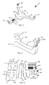
- Fig. 1 shows a production line 1 for the production or production of an article 2 of several components.
- the object 2 is a motor vehicle and the production plant 1 may be a production line for a vehicle, in particular motor vehicle, truck, aircraft, etc.
- the production facility 1 is not limited thereto and may be a production facility for any other industrially manufactured item.
- the production plant 1 in Fig. 1 has a device 10 for handling a load, such as a component of the article 2.
- the component may in particular a body part of the in Fig. 1 be shown as a motor vehicle 2.
- the component may also be a tenter or framer, which is useful for tensioning components of a vehicle in a vehicle body manufacture.
- the production plant 1 in Fig. 1 also has a moving device 20, on which the device 10 is arranged.
- the device 10 is attached to the moving device 20 so that the moving device 20 can move the device 10 in space.
- a load handled by the device 10 is also moved in space.
- the movement device 20 is shown as a robot.
- the moving device 20 can also have any other shape, such as a pivoting arm, a lifting device with a telescopic arm, etc.
- Fig. 2 shows the device 10 in a plan view in more detail.
- the device 10 has a first to third cantilever 11 to 13, a connecting body 14 for connecting the cantilevers 11 to 13 and a coating 15, with which the device 10 is coated on the outside.
- the coating 15 is in Fig. 2 only indicated in more detail at one point.
- a first mounting device 111 is arranged.
- a second mounting device 121 is arranged.
- a third mounting device 131 is arranged, which in Fig. 2 barely visible.
- a handling device for example in the form of a fluidic gripper, in particular a pneumatic gripper, and / or a mechanical gripper, in particular cable gripper, and / or an electric gripper and / or a magnetic coupling is mounted on the mounting device 111, 121, 131, the grippers can to engage and thus handle a load.
- the handling device can also be a tool that is needed in the production in the production plant 1.
- openings 141 are provided in the connecting body 14 which are usable for mounting the device 10 on the moving device 20.
- the assembly of the device 10 on the movement device 20 can also be done by means of automatic docking and undocking.
- Fig. 2 not all openings 141 provided with a reference numeral.
- openings 141 are openings 151 to 156 of the coating 15 provided so that the coating 15 comes close to the openings 141, the openings 141 but exposed.
- the openings 141 are therefore not coated with the coating 15.
- no coupling device is still mounted, with which the device 10 is coupled to the movement device 20.
- Fig. 3 shows the device 10 in a lower view in more detail.
- additional openings 142 are provided at the bottom of the connecting body 14.
- a mounting device 112 in the form of an opening for mounting a tool, a camera, a sensor, another gripper or the like is provided on the side of the first arm 11.
- the in Fig. 3 only indicated coating 15 around the mounting device 112 around provided such that the coating 15 comes close to the mounting device 112, the mounting device 112, however, is exposed and thus not coated with the coating 15.
- Fig. 4 shows a detail of Fig. 3 with the second mounting device 121 in more detail.
- the second mounting device 121, as well as the first and third mounting means 111, 131 are designed such that a handling device, such as a gripper, a tool, a camera or the like can be mounted on it.
- the mounting device 121 has a plurality of openings 121A, with which a handling device, in particular by screws, etc., can be attached.
- the coating 15 consists of a composite of carbon fiber and / or glass fiber and / or basalt fiber with resin.
- the coating 15 is thus a fiber-reinforced plastic.
- the coating 15 is laminated over a framework and thus brings additional strength and also the required rigidity. This is described in more detail below.
- the coating 15 may also consist of continuously endless fiber-reinforced organo-material, in particular organo-sheet. Such includes thermoplastic. Thereby, the continuous fiber-reinforced organo-material can be attached to the skeleton by heating above the melting temperature of the thermoplastic resin and then laminated to the skeleton.
- Another alternative is the spraying of fiber composites, which offer the same properties as the fiber material.
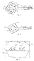
- FIG. 12 illustrates individual parts of a framework from which a part of the apparatus 10 is assembled, as in FIG Fig. 6 to Fig. 11 shown.
- the individual parts 143 to 149 form the individual parts, from which the framework for the connecting body 14 with the openings 141, 142 is assembled.
- the items 146 to 149 is in Fig. 5 for the sake of clarity, only one of the individual parts provided with a reference numeral.
- the items 143 and 144 are spaced apart by the items 146 to 149 by mounting the items 146 to 149 between or on the pieces 143 and 144, respectively.
- the items 146 to 149 may thus also be referred to as spacers.
- the item 145 later serves as a coupling device for coupling the device 10 to the movement device 20.
- the items 122 to 125 form individual parts, from which the framework for the boom 12 is assembled. In Fig.
- FIG. 5 only one item of the items 122 to 125, which are used for the boom 12, is shown.
- tabs 30 are provided, which are in and through through holes 31 of the items 143, 144 pluggable.
- the item 122 also has through holes 31, in and through which tabs 30 of the items 123 to 125 are pluggable.
- a tab 30 and / or a passage opening 31 are hereinafter also referred to as plug-in device 30, 31.
- plug-in device 30 In Fig. 5
- not all lugs 30 and passage openings 31 of the individual parts 143, 144, 122 to 125 are provided with a reference numeral.
- the items 143 to 149 and 122 to 125 may be made of, for example, metal, especially aluminum, iron, etc., plastic, wood, and combinations thereof.
- the items 143, 144 and 122 to 125 may be made in particular of galvanized sheet metal. Other materials are also conceivable which can realize the necessary basic strength or stability for the framework.
- Fig. 6 to Fig. 11 show the device 10, on which a handling device 17 is mounted in the form of a gripper. For the sake of clarity, not all are in Fig. 6 to Fig. 11 Parts provided with a reference numeral.
- the plug-in devices 30, 31 are only partially mounted.
- the tabs 30 of the individual parts 122 to 125 are indeed inserted into the passage opening 31 and inserted through the passage opening 31 up to the edge of the individual parts 143, 144, 122 to 125.
- the tabs 30 are not yet bent over and secured therewith, as in FIG Fig. 12 for the items 143 and 125 shown. So that's the items in Fig. 6 to Fig. 11 not quite attached to each other.
- the tabs 30 are here designed so that they can be easily bent with the thumb of one hand, so without tools. So it's not another tool to assemble of the framework formed from items 143 to 149 and 122 to 125 required.
- At least one of the tabs 30 can have such a material thickness that it can no longer be bent by hand or by the thumb. In such a case, a tool can be used for bending the tabs 30.
- the framework may be provided with the coating 15, as described above and below.
- Fig. 13 shows very schematically a method for producing the device 10.
- a step S1 several individual parts, for example the individual parts 143, 144 and 122 to 125, cut from a planar material, in particular galvanized sheet.
- the cutting can take place with a laser and / or a milling device by means of milling and / or a punching device by means of punching and / or a water jet cutting device by means of water cutting and / or other suitable situational processing, such as spark erosion, electroerosion, etc.
- the passage openings 31 are produced.
- the flow proceeds to a step S2.
- step S2 the items, for example, the items 143 to 149 and 122 to 125 are assembled.
- the individual parts are assembled in such a way that together they form the three-dimensional framework, as in FIG FIG. 6 to FIG. 12 illustrated.
- the assembly can be performed without tools, by interlocking plug-in devices of the items are positively mounted as the three-dimensional framework.
- the mounting devices 111, 121, 131 and possibly also the handling devices 17 are already mounted on the frame at their respective desired position. Thereafter, the flow proceeds to a step S3.
- fiber material is applied around the three-dimensional skeleton fabricated at step S2 to produce the coating 15.
- This may include, for example, coating the three-dimensional framework with a tubular fibrous material.
- individual fibers or fiber mats can also be attached to the framework, in particular laid on top.
- the fiber material may be applied to the framework in one or more layers. It is also possible that the fiber material only at predetermined Sites of the scaffold one or more layers attached. For example, more layers of fiber material may be applied at locations of the scaffold where greater forces will act than at locations of the scaffold where smaller forces will act.
- the fibrous material is applied so as to expose any openings intended to be used to attach the device to the mover 20 or to attach a handling device, etc. Thereafter, the flow proceeds to a step S4.
- step S4 resin is applied to the fiber material attached at step S3.
- the application can be done for example with a brush. It is sufficient that the resin is present between the fibers of the fiber material. Excess resin can be easily scraped off.
- the resin-impregnated fiber material which in the case of a fabric can also be referred to as lamination mats, resembles a wet tissue.
- the step S4 may be omitted, for example, when the fiber material is sprayed with resin as a fiber composite material.
- the step S3 and S4 can also be considered as a common manufacturing step, when the fiber material is applied and applied simultaneously by resin coating. Thereafter, the flow proceeds to a step S5.
- step S5 the resin / fiber composite formed in step S3 is cured as a fiber reinforced plastic and thus the coating 15 of the framework of the device 10 is formed.
- Curing may be either cold or hot cure depending on the type of lamination chosen.
- the construction of the device 10 is given additional strength and rigidity.
- this also avoids re-bending of the tabs 30 protruding through the passage openings 31.
- the skeleton is closed to the outside except for the openings 141, 142, 112, so that foreign matter such as dust, liquid, etc. is prevented from entering. Thereafter, the process is completed.
- a building block module for the device 10 is provided, with which it is possible to create a lightweight cost-effective gripping system in plug-in construction.
- the framework of the device 10 obtains additional strength by the cladding with the fiber material.
- the required rigidity of the device 10 can be ensured.
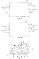
- Fig. 14 shows the item 124 in detail, which item 124 is used for a frame of a device 10 according to a second embodiment.
- the device 10 according to the present embodiment is largely implemented in the same manner as in FIG Referring to the first embodiment described. Therefore, only the differences from the first embodiment will be described below.
- This in Fig. 14 shown item 124 has a centering plug, the in Fig. 14 two tabs 30, two tabs 32 and a web 33 includes.
- the lugs 32 and the ridge 33 each slightly project from the edge of the item 124, as indicated by the dashed lines in FIG Fig. 14 illustrated.
- the two tabs 30 each protrude a lot further from the edge of the item 124 than the tabs 32.
- the tabs 32 and optionally the web 33 so far from the edge of the item 124 cantilever out that they into a through hole 31 of a other item, in this case an item 122, but can not protrude from the through hole 31 when the tabs 30 are bent, as in Fig. 12 shown in the first embodiment.
- the overall width of the tabs 30, the tabs 32 and the web 33 at the edge of the item 124 is slightly smaller than the width of a through hole 31, so that the tabs 30, tabs 32 and the web 33 of the item 124 form a positive connection with the passage opening 31 of the item 122, when mounted thereon in a similar manner as in FIG FIG. 6 to FIG. 12 for the items 123, 125 shown.
- the total width corresponds to the length of one of the dashed lines in Fig. 14 .
- the form-fitting acts as a centering anti-slip device for the interlocking items 122 to 125, 143, 144 and thus also contributes to component stiffness.
- the component rigidity in this case refers both to the scaffold constructed from the individual parts 122 to 125, 143 to 149, and to the device 10 thus completed.
- the other individual parts of the device 10, on which tabs 30 are present, can be designed in the same way as the item 124 with tabs 30 and tabs 32.
- the centering plug comprises no web 33, as in Fig. 15 shown.
- a first modification in this case only one tab 30 is present, on whose sides in each case a nose 32 is arranged, as in Fig. 15 illustrated on the left edge of the item 124.
- two tabs 30 are provided, on whose sides in each case a nose 32 is arranged, as in Fig. 15 illustrated on the right edge of the item 124.
- the edge of the item 124 does not protrude between the tabs 30 but lies, for example, on the same straight line as the edge of the piece Item 124.
- the edge of the item 124 may be notched between the tabs 30 against the other edge of the item 124 from the item 124.
- the centering plug-in device does not comprise lugs 32, as in FIG Fig. 16 shown on the left edge of the item 124.
- only one nose 32 may be present, as in FIG Fig. 16 shown on the right edge of the item 124.
- the positive connection between the individual parts 122 to 125, 143, 144 for the anti-slip device by means of at least the tabs 30 and possibly a nose 32 is formed.
- individual parts 35, 36 of the framework of the device 10 have an edge toothing 37, as in FIG Fig. 17 shown.
- the edges of the individual parts 35, 36 are formed so that they interlock when the individual parts 35, 36 are brought together at their edges.
- the individual parts 35, 36 are assembled with a single part 38 and further non-visible individual parts 35, 36 to form a square profile, in which the item 38 forms a lid arranged in the square profile.
- the item 38 has tabs 30 which are in Fig. 17 are guided through the through holes 31 of the items 35, 36 and bent to the items 35, 36. For clarity in Fig. 17 not all tabs 30 and through holes 31 provided with a reference numeral.
- the items 35, 36, 38 have openings 39 which are in Fig. 17 are also formed as through holes 39, so that the framework is even easier.
- the openings 39 may be designed in particular as a slot or round hole, as in Fig. 17 shown. However, other shapes for the openings 39 are conceivable. Depending on the thickness of the material, the openings 39 can also form a blind hole.
- the bending tabs 30 are not arranged in the edge region of the item 35 in the frame of the individual parts 35, 36, 38 with the edge teeth 37, as described in the previous embodiments, but further arranged on the inside of the item 36. As a result, the framework formed from the individual parts 35, 36 and an individual part 38 becomes even more stable.
- the edge gearing can be used in the method that is related to Fig. 13 is prepared at step S1 by cutting or removing the desired notches on the individual parts 35, 36 prepared.
- the shape of the device 10 is arbitrary.
- the number of arms 11, 12, 13 can be freely selected.
- only a boom or no boom is possible.
- the number of connecting body 14 is arbitrary. The same applies to the shape of the arms 11, 12, 13 and the connecting body 14.
- edges of the individual parts are preferably rounded. Preference is given to constructions which do not have sharp-edged shapes. This favors the lamination with the fiber material.
- the fiber material can be applied to the component 125 filler of lightweight materials, such as cardboard, felt, etc., to the between the components 125, 143 in Fig. 12 compensate offset shown. As a result, the bending radius of the fibers of the fiber material can be optimized.
- one or more individual parts of the framework of the device 10 consist of a tubular material.
- planar items are usually easier and / or cheaper moldable, transportable and processable, planar items are preferred.
- the plug-in device can also be designed as a snaphaken and / or Sch noirspriegel instead of a tab 30.
- the through hole 31 is to be formed, in which the snaphaks and / or Sch noirspriegel, etc. to intervene. It is also a combination of tab 30 and Snaphaken or a combination of tab 30 and Sch noirspriegel possible.
- flap 30, Snaphaken and welding bow for a plug-in device can be combined.
- more than one tab 30 and / or snaphaken and / or Sch noirspriegel can be used for a plug-in device.
- the steps S1 and / or S2 of the method can also be carried out by a manufacturer other than the manufacturer who produces the coating 15 by means of the steps S3 to S5.
- a modular system with the items according to Fig. 5 be supplied, so that a manufacturer of the device 10 only needs to perform steps S2 to S5.
- the fiber is aligned in the direction of the expected load to optimally absorb the forces.
- the coating 15 closes the framework to the outside with the exception of the openings 141, 142, 112, this is not absolutely necessary.
- the coating 15 and thus the fiber material for the coating 15 to be applied only to one side of the framework.
Landscapes
- Engineering & Computer Science (AREA)
- Mechanical Engineering (AREA)
- Robotics (AREA)
- Moulding By Coating Moulds (AREA)
- Manufacturing & Machinery (AREA)
- Manipulator (AREA)
Description
Die vorliegende Erfindung bezieht sich auf eine Vorrichtung zur Verwendung beim Handhaben einer Last und ein Verfahren zum Herstellen einer derartigen Vorrichtung. Insbesondere bezieht sich die vorliegende Erfindung auf eine Vorrichtung zur Verwendung beim Handhaben einer Last und ein Verfahren zum Herstellen einer derartigen Vorrichtung, die in einer Produktionsanlage zum Einsatz kommen kann. Die Produktionsanlage ist insbesondere eine Fertigungsstraße für ein Fahrzeug.The present invention relates to a device for use in handling a load and a method of manufacturing such a device. More particularly, the present invention relates to an apparatus for use in handling a load and a method of manufacturing such an apparatus which may be used in a production facility. The production plant is in particular a production line for a vehicle.
In Produktionsanlagen für industriell gefertigte Gegenstände, wie beispielsweise Kraftfahrzeuge, Mediengeräte, Möbel, usw., werden üblicherweise einzelne Bauteile des zu fertigenden Gegenstands von einem Ort zum anderen bewegt und/oder das Bauteil um seine Achse geschwenkt und/oder für eine bestimmte Behandlungsweise in einer speziellen Position gehalten, usw. Hierzu wird derzeit im Stand der Technik ein Greifwerkzeug verwendet, das sowohl die Last des Gegenstands handhaben kann als auch ausreichend dimensioniert ist, um den Gegenstand sicher und ausreichend schnell von einer Ausgangsposition in eine gewünschte andere Position zu bewegen und ihn an dieser Position auch zu halten.In production facilities for industrially manufactured items such as motor vehicles, media equipment, furniture, etc., usually individual components of the object to be manufactured are moved from one place to another and / or the component is pivoted about its axis and / or for a particular treatment in one For this purpose, a gripping tool is currently used in the prior art, which can both handle the load of the object and is sufficiently dimensioned to move the object safely and sufficiently quickly from a starting position to a desired other position and him to hold on to this position as well.
Die derzeit in solchen Produktionsanlagen verwendeten Greifwerkzeuge sind vergleichsweise schwer. Dadurch ist wiederum eine Anlage, in die das Greifwerkzeug integriert ist, für eine große Handhabungslast auszulegen. Als weitere Folge davon ist die benötigte Antriebskraft zum Antrieb eines solchen Greifwerkzeugs relativ hoch. Ein weiterer Nachteil besteht darin, dass eine Umrüstung der Produktionsanlage zwischen verschiedenen Greifwerkzeugen, die jeweils für spezielle Greifaufgaben gestaltet sind, relativ zeitaufwändig ist. Dies führt zu langen Stillstandzeiten der Produktionsanlage.The gripping tools currently used in such production plants are comparatively heavy. This, in turn, a system in which the gripping tool is integrated, designed for a large handling load. As a further consequence, the required driving force for driving such a gripping tool is relatively high. Another disadvantage is that a conversion of the production plant between different gripping tools, which are each designed for special gripping tasks, is relatively time consuming. This leads to long downtimes of the production plant.
Es besteht jedoch weiter Bedarf nach einer Vorrichtung zur Verwendung beim Handhaben einer Last, welche ein geringes Eigengewicht hat und dennoch so stabil ist, dass sie Lasten handhaben kann, deren Gewicht das Eigengewicht der Vorrichtung um ein Vielfaches übersteigen können und dabei sehr kostengünstig und flexibel herstellbar und gegebenenfalls an sich ändernde Produktionsbedingungen in der Produktionsanlage einfach und kostengünstig anpassbar ist.
However, there is still a need for a device for use in handling a load which has a low deadweight and yet is so stable that it can handle loads whose weight can exceed the dead weight of the device many times while being very cost effective and flexible to manufacture and, where appropriate, changing production conditions in the production plant is easily and inexpensively customizable.
Daher ist es Aufgabe der vorliegenden Erfindung, eine Vorrichtung zur Verwendung beim Handhaben einer Last und ein Verfahren zum Herstellen einer derartigen Vorrichtung bereitzustellen, mit welchen die zuvor genannten Probleme gelöst werden können. Insbesondere soll eine Vorrichtung zur Verwendung beim Handhaben einer Last und ein Verfahren zum Herstellen einer derartigen Vorrichtung bereitgestellt werden, bei welcher die Vorrichtung im Vergleich zu herkömmlichen Vorrichtungen leichtgewichtig, sehr flexibel anpassbar und kostengünstig herstellbar ist.Therefore, it is an object of the present invention to provide a device for use in handling a load and a method of manufacturing such a device, with which the aforementioned problems can be solved. In particular, a device for use in handling a load and a method for producing such a device should be provided, in which the device compared to conventional devices is lightweight, very flexible adaptable and inexpensive to produce.
Diese Aufgabe wird durch eine Vorrichtung zur Verwendung beim Handhaben einer Last nach Patentanspruch 1 gelöst. Die genannte Vorrichtung ist sehr leichtgewichtig, einfach und kostengünstig herstellbar und sehr flexibel und einfach anpassbar. Die Vorrichtung kann an gewünschten Stellen beispielsweise um einen oder mehrere Ausleger für Handhabungseinrichtungen, wie insbesondere Greifer, ergänzt werden, indem der faserverstärkte Kunststoff aufgerauht und dadurch zum Andocken eines weiteren Greifarms vorbereitet wird. Dadurch ist auch eine Reparatur der Vorrichtung einfach möglich. Hierbei können auch Befestigungseinrichtungen, wie Bohrungen für Schrauben usw., Nietung, usw. am Gerüst Halt finden.This object is achieved by a device for use in handling a load according to
"Handhaben" ist hierbei insbesondere zu verstehen als greifen, ansaugen, halten, umsetzen, positionieren an einer bestimmten Stelle, bewegen, wie schwenken, drehen, schieben, heben, usw., tragen, stützen, usw."Handling" is to be understood in particular as gripping, sucking, holding, repositioning, positioning at a particular location, moving, such as pivoting, rotating, pushing, lifting, etc., carrying, supporting, etc.
Bei der zuvor beschriebenen Vorrichtung ist das Gerüst aus beliebig konfigurierbaren Einzelteilen zusammengesetzt. Das Gerüst erhält durch den Überzug oder eine Ummantelung mit dem faserverstärkten Kunststoff zusätzliche Festigkeit und auch die erforderliche Steifigkeit.In the apparatus described above, the framework of arbitrarily configurable items is composed. The framework obtains additional strength and also the required rigidity by the coating or a sheathing with the fiber-reinforced plastic.
Die zuvor beschriebene Vorrichtung hat bei einer Ausgestaltung mit beispielsweise drei Auslegern, die zum Handhaben beispielsweise eines Karosserieteils eines Fahrzeugs verwendbar ist, ein gegenüber dem Stand der Technik deutlich reduziertes Gewicht. Das Gleiche gilt für andere Ausgestaltungen.The device described above has in a configuration with, for example, three arms, which is useful for handling, for example, a body part of a vehicle, a weight compared to the prior art significantly reduced. The same applies to other embodiments.
Vorteilhafte weitere Ausgestaltungen der Vorrichtung sind in den abhängigen Patentansprüchen angegeben.Advantageous further embodiments of the device are specified in the dependent claims.
Bei der zuvor beschriebenen Vorrichtung können die mehreren Einzelteile planare Elemente sein, welche mindestens eine Steckeinrichtung umfassen, mit welcher die Einzelteile als das dreidimensionale Gerüst zusammengebaut werden können. Somit ist mit der zuvor beschriebenen Vorrichtung ein leichtes und kostengünstiges Greifsystem in Steckbauweise bereitgestellt.In the apparatus described above, the plurality of individual parts may be planar elements comprising at least one plug-in device with which the individual parts can be assembled as the three-dimensional framework. Thus, with the device described above, a lightweight and inexpensive gripping system in plug-in construction is provided.
Die Einzelteile können auch planare Elemente sein, welche ineinandergreifende Steckeinrichtungen umfassen, so dass die Einzelteile formschlüssig als das dreidimensionale Gerüst montiert werden können.The individual parts can also be planar elements, which comprise interlocking plug-in devices, so that the individual parts can be mounted in a form-fitting manner as the three-dimensional framework.
Es besteht die Möglichkeit, dass die Einzelteile mindestens eine Steckeinrichtung umfassen, die als Lasche und Durchgangsöffnung ausgestaltet ist, wobei die Steckeinrichtung derart ausgestaltet ist, dass die Steckeinrichtung eines Einzelteils in eine Durchgangsöffnung eines anderen Einzelteils eingesteckt und anschließend werkzeuglos an dem anderen Einzelteil befestigt werden kann.It is possible that the items comprise at least one plug-in device, which is designed as a tab and passage opening, wherein the plug-in device is configured such that the plug-in device of a single part can be inserted into a through hole of another item and then attached without tools to the other item ,
Bevorzugt weisen Einzelteile des Gerüsts der Vorrichtung eine Kantenverzahnung auf. Die Kantenverzahnung kann die bei Belastung auftretenden Torsionskräfte besser aufnehmen und kompensieren. Dadurch kann die Stabilität des Gerüsts aus den Einzelteilen noch weiter erhöht werden.Preferably, individual parts of the frame of the device have an edge toothing. The serration can better absorb and compensate for the torsional forces occurring under load. As a result, the stability of the framework from the individual parts can be further increased.
Bei der zuvor genannten Vorrichtung kann das Gerüst mindestens einen Ausleger aufweisen, an dessen Ende eine mechanische oder fluidische Handhabungseinrichtung an einer der mindestens einen Montageeinrichtung angeordnet ist.In the case of the abovementioned device, the framework may have at least one arm, at the end of which a mechanical or fluidic handling device is arranged on one of the at least one mounting device.
Falls die Vorrichtung mehrere Handhabungseinrichtungen aufweist, können diese zum Handhaben eines bei der Produktion des Gegenstands verwendbaren Teils zusammenwirken.If the device comprises a plurality of handling devices, these may cooperate to handle a part usable in the production of the article.
Bei der zuvor genannten Vorrichtung kann der faserverstärkte Kunststoff Kohlefaser und/oder Glasfaser und/oder Basaltfaser und/oder kontinuierlich endlosfaserverstärktes Organomaterial umfassen.In the aforementioned apparatus, the fiber-reinforced plastic may comprise carbon fiber and / or glass fiber and / or basalt fiber and / or continuously continuous fiber-reinforced organo material.
Die Vorrichtung kann zum Handhaben von Bauteilen zur Herstellung eines Fahrzeugs und/oder von Spannrahmen zum Spannen von Bauteilen eines Fahrzeugs bei einer Herstellung der Karosserie eines Fahrzeugs dienen. Zusätzlich oder alternativ ist es auch möglich, um die Vorrichtung mit einer Bewegungsvorrichtung zu koppeln, dass die Vorrichtung eine Kopplungseinrichtung aufweist. Somit kann die Vorrichtung beispielsweise als Tragevorrichtung Verwendung finden.The device can be used for handling components for producing a vehicle and / or clamping frames for tensioning components of a vehicle in a production of the body of a vehicle. Additionally or alternatively, it is also possible to couple the device with a movement device that the device has a coupling device. Thus, the device can be used, for example, as a carrying device.
Die zuvor beschriebene Vorrichtung kann Teil einer Produktionsanlage zur Produktion eines Gegenstands sein. Die Produktionsanlage umfasst zudem mindestens eine Handhabungseinrichtung, die an einer der mindestens einen Montageeinrichtung montiert ist, und eine Bewegungsvorrichtung zur Bewegung der Vorrichtung im Raum.The apparatus described above may be part of a production facility for the production of an item. The production plant further comprises at least one handling device mounted on one of the at least one mounting device and a movement device for moving the device in space.
Die Aufgabe wird zudem durch ein Verfahren zum Herstellen einer Vorrichtung beim Handhaben einer Last nach Patentanspruch 11 gelöst. Das Verfahren erzielt die gleichen Vorteile, wie sie zuvor in Bezug auf die Vorrichtung genannt sind.The object is also achieved by a method for producing a device when handling a load according to
Vorteilhafte weitere Ausgestaltungen des Verfahrens sind in den abhängigen Patentansprüchen angegeben.Advantageous further embodiments of the method are specified in the dependent claims.
Der Schritt des Zusammenfügens kann werkzeuglos ausgeführt werden, indem ineinandergreifende Steckeinrichtungen der Einzelteile formschlüssig als das dreidimensionale Gerüst montiert werden.The assembling step can be performed without tools by positively mounting interlocking plug-in devices of the individual parts as the three-dimensional framework.
Möglicherweise hat das Verfahren zudem einen Schritt eines Schneidens, mit einem Laser und/oder einer Fräseinrichtung und/oder einer Stanzeinrichtung und/oder einer Wasserstrahlschneideinrichtung, mehrerer Einzelteile aus einem planaren Werkstoff.The method may also include a step of cutting, with a laser and / or a milling device and / or a punching device and / or a water jet cutting device, a plurality of individual parts of a planar material.
Bei dem Verfahren kann der Schritt des Anbringens von Fasermaterial ein Überziehen des dreidimensionalen Gerüsts mit einem schlauchförmigen Fasermaterial umfassen.In the method, the step of applying fibrous material may include coating the three-dimensional framework with a tubular fibrous material.
Darüber hinaus ist es möglich, dass der Schritt des Anbringens von Fasermaterial derart ausgeführt wird, dass Öffnungen freiliegen, die zum Anbringen der Vorrichtung an einer Bewegungsvorrichtung zur Bewegung der Vorrichtung im Raum dienen.Moreover, it is possible that the step of applying fibrous material is performed such that there are exposed openings for mounting the device on a moving device for moving the device in space.
Weitere mögliche Implementierungen der Erfindung umfassen auch nicht explizit genannte Kombinationen von zuvor oder im Folgenden bezüglich der Ausführungsbeispiele beschriebenen Merkmale oder Ausführungsformen. Dabei wird der Fachmann auch Einzelaspekte als Verbesserungen oder Ergänzungen zu der jeweiligen Grundform der Erfindung hinzufügen.Further possible implementations of the invention also include not explicitly mentioned combinations of features or embodiments described above or below with regard to the exemplary embodiments. The skilled person will also add individual aspects as improvements or additions to the respective basic form of the invention.
Nachfolgend ist die Erfindung unter Bezugnahme auf die beiliegende Zeichnung und anhand von Ausführungsbeispielen näher beschrieben. Es zeigen:
-
Fig. 1 eine stark vereinfachte Ansicht einer Produktionsanlage mit einer Vorrichtung gemäß einem ersten Ausführungsbeispiel; -
Fig. 2 eine vereinfachte dreidimensionale Draufsicht auf die Vorrichtung gemäß dem ersten Ausführungsbeispiel; -
Fig. 3 eine vereinfachte dreidimensionale Untersicht unter die Vorrichtung gemäß dem ersten Ausführungsbeispiel; -
Fig. 4 eine dreidimensionale Teilunteransicht der Vorrichtung gemäß dem ersten Ausführungsbeispiel; -
Fig. 5 eine Darstellung von Einzelteilen eines Teils der Vorrichtung gemäß dem ersten Ausführungsbeispiel; -
Fig. 6 eine vereinfachte dreidimensionale Draufsicht auf ein aus den Einzelteilen vonFig. 5 montiertes Gerüst der Vorrichtung gemäß dem ersten Ausführungsbeispiel; -
Fig. 7 eine vereinfachte dreidimensionale Untersicht unter das Gerüst vonFig. 6 ; -
Fig. 8 und Fig. 9 jeweils eine Schnittansicht des Gerüsts vonFig. 6 ; -
Fig. 10 eine Draufsicht auf das Gerüst vonFig. 6 ; -
Fig. 11 eine Untersicht unter das Gerüst vonFig. 6 ; -
Fig. 12 ein Detail in Bezug auf das Gerüst vonFig. 6 ; -
Fig. 13 ein Flussdiagramm eines Verfahrens zum Herstellen einer Vorrichtung zum Handhaben einer Last gemäß dem Ausführungsbeispiel; -
Fig. 14 ein Detail eines Einzelteils einer Vorrichtung gemäß einem zweiten Ausführungsbeispiel; -
Fig. 15 ein Detail eines Einzelteils einer Vorrichtung gemäß einem dritten Ausführungsbeispiel; -
Fig. 16 ein Detail eines Einzelteils einer Vorrichtung gemäß einem vierten Ausführungsbeispiel; und -
Fig. 17 ein Detail eines Gerüsts einer Vorrichtung gemäß einem fünften Ausführungsbeispiel.
-
Fig. 1 a greatly simplified view of a production plant with a device according to a first embodiment; -
Fig. 2 a simplified three-dimensional plan view of the device according to the first embodiment; -
Fig. 3 a simplified three-dimensional bottom view of the device according to the first embodiment; -
Fig. 4 a three-dimensional partial bottom view of the device according to the first embodiment; -
Fig. 5 an illustration of parts of a part of the device according to the first embodiment; -
Fig. 6 a simplified three-dimensional plan view of one of the items fromFig. 5 mounted framework of the device according to the first embodiment; -
Fig. 7 a simplified three-dimensional bottom view under the framework ofFig. 6 ; -
FIGS. 8 and 9 each a sectional view of the framework ofFig. 6 ; -
Fig. 10 a plan view of the framework ofFig. 6 ; -
Fig. 11 a soffit under the scaffolding ofFig. 6 ; -
Fig. 12 a detail regarding the scaffolding ofFig. 6 ; -
Fig. 13 a flowchart of a method for producing a device for handling a load according to the embodiment; -
Fig. 14 a detail of an item of a device according to a second embodiment; -
Fig. 15 a detail of an item of a device according to a third embodiment; -
Fig. 16 a detail of an item of a device according to a fourth embodiment; and -
Fig. 17 a detail of a skeleton of a device according to a fifth embodiment.
In den Figuren sind gleiche oder funktionsgleiche Elemente, sofern nichts anderes angegeben ist, mit denselben Bezugszeichen versehen.In the figures, identical or functionally identical elements are provided with the same reference numerals, unless stated otherwise.
Die Produktionsanlage 1 in
Wie in
Bei der Vorrichtung 10 von
Wie aus
Die Einzelteile 143 bis 149 und 122 bis 125 können beispielsweise aus Metall, insbesondere Aluminium, Eisen, usw., Kunststoff, Holz und Kombinationen hieraus gefertigt sein. Die Einzelteile 143, 144 und 122 bis 125 können insbesondere aus verzinktem Blech gefertigt sein. Es sind auch andere Materialien denkbar, welche die nötige Grundfestigkeit oder -stabilität für das Gerüst realisieren können.The
In
Sobald das Gerüst aus den Einzelteilen 143 bis 149 und 122 bis 125 zusammengebaut ist, wie zuvor und nachfolgend beschrieben kann es mit dem Überzug 15 versehen werden, wie zuvor und nachfolgend beschrieben.Once the framework is assembled from the items 143-149 and 122-125, as described above and below, it may be provided with the
Bei dem Schritt S2 werden die Einzelteile, beispielsweise die Einzelteile 143 bis 149 und 122 bis 125 zusammengefügt. Hierbei werden die Einzelteile derart zusammengefügt, dass sie zusammen das dreidimensionale Gerüst bilden, wie in
Bei dem Schritt S3 wird um das dreidimensionale Gerüst herum, das bei dem Schritt S2 hergestellt wurde, Fasermaterial angebracht, um den Überzug 15 herzustellen. Dies kann beispielsweise ein Überziehen des dreidimensionalen Gerüsts mit einem schlauchförmigen Fasermaterial umfassen. Alternativ oder zusätzlich können auch einzelne Fasern oder Fasermatten an dem Gerüst angebracht, insbesondere aufgelegt, werden. Je nach gewünschter Stabilität und Tragkraft der Vorrichtung 10 kann das Fasermaterial in einer Schicht oder mehreren Schichten an dem Gerüst angebracht werden. Hierbei ist es auch möglich, dass das Fasermaterial nur an vorbestimmten Stellen des Gerüsts ein- oder mehrlagig angebracht wird. Beispielsweise können an Stellen des Gerüsts, an denen größere Kräfte wirken werden, mehr Schichten des Fasermaterials angebracht werden als an Stellen des Gerüsts, an denen kleinere Kräfte wirken werden. Zudem wird das Fasermaterial derart angebracht, dass alle Öffnungen freiliegen, die zum Anbringen der Vorrichtung an der Bewegungsvorrichtung 20 oder zum Anbringen einer Handhabungseinrichtung usw. dienen sollen. Danach geht der Fluss zu einem Schritt S4 weiter.At step S3, fiber material is applied around the three-dimensional skeleton fabricated at step S2 to produce the
Bei dem Schritt S4 wird auf das bei dem Schritt S3 angebrachte Fasermaterial Harz aufgebracht. Das Aufbringen kann beispielsweise mit einem Pinsel erfolgen. Hierbei ist es ausreichend, dass das Harz zwischen den Fasern des Fasermaterials vorhanden ist. Überschüssiges Harz kann einfach abgestrichen werden. Das harzgetränkte Fasermaterial, das im Falle eines Gewebes auch als Laminierungsmatten bezeichnet werden kann, ähnelt einem nassen Gewebe. Der Schritt S4 kann beispielsweise entfallen, wenn das Fasermaterial mit Harz als Faserverbundwerkstoff aufgesprüht wird. Zudem können der Schritt S3 und S4 auch als ein gemeinsamer Fertigungsschritt angesehen werden, wenn das Fasermaterial aufgelegt und per Harzanstrich simultan aufgetragen wird. Danach geht der Fluss zu einem Schritt S5 weiter.At step S4, resin is applied to the fiber material attached at step S3. The application can be done for example with a brush. It is sufficient that the resin is present between the fibers of the fiber material. Excess resin can be easily scraped off. The resin-impregnated fiber material, which in the case of a fabric can also be referred to as lamination mats, resembles a wet tissue. The step S4 may be omitted, for example, when the fiber material is sprayed with resin as a fiber composite material. In addition, the step S3 and S4 can also be considered as a common manufacturing step, when the fiber material is applied and applied simultaneously by resin coating. Thereafter, the flow proceeds to a step S5.
Bei dem Schritt S5 wird der bei dem Schritt S3 gebildete Harz/Fasermaterialverbund als faserverstärkter Kunststoff ausgehärtet und somit der Überzug 15 des Gerüsts der Vorrichtung 10 gebildet. Die Aushärtung kann je nach gewählter Laminierungsart entweder eine Kalt- oder eine Warmaushärtung sein. Durch das Einlaminieren des Gerüsts wird zum einen der Konstruktion der Vorrichtung 10 zusätzliche Festigkeit und Steifigkeit verliehen. Zum anderen wird dadurch auch ein wieder Aufbiegen der durch die Durchgangsöffnungen 31 durchragenden Laschen 30 vermieden. Das Gerüst wird nach außen mit Ausnahme der Öffnungen 141, 142, 112 abgeschlossen, so dass ein Eindringen von Fremdstoffen, wie Staub, einer Flüssigkeit, usw. verhindert wird. Danach ist das Verfahren beendet.In step S5, the resin / fiber composite formed in step S3 is cured as a fiber reinforced plastic and thus the
Somit ist ein Baukastenmodul für die Vorrichtung 10 bereitgestellt, mit welches es möglich wird, ein leichtes kostengünstiges Greifsystem in Steckbauweise zu erstellen. Das Gerüst der Vorrichtung 10 erhält durch die Ummantelung mit dem Fasermaterial zusätzliche Festigkeit. Zudem kann die erforderliche Steifigkeit der Vorrichtung 10 gewährleistet werden.Thus, a building block module for the
Das in
Die Gesamtbreite der Laschen 30, der Nasen 32 und des Stegs 33 an der Kante des Einzelteils 124 ist etwas kleiner als die Breite einer Durchgangsöffnung 31, so dass die Laschen 30, Nasen 32 und der Steg 33 des Einzelteils 124 einen Formschluss mit der Durchgangsöffnung 31 des Einzelteils 122 bilden, wenn sie an diesem in ähnlicher Weise montiert sind, wie in
Die anderen Einzelteile der Vorrichtung 10, an welchen Laschen 30 vorhanden sind, können auf die gleiche Weise wie das Einzelteil 124 mit Laschen 30 und Nasen 32 ausgeführt sein.The other individual parts of the
Gemäß einem dritten Ausführungsbeispiel umfasst die Zentrier-Steckeinrichtung keinen Steg 33, wie in
Gemäß einem vierten Ausführungsbeispiel umfasst die Zentrier-Steckeinrichtung keine Nasen 32, wie in
Gemäß einem fünften Ausführungsbeispiel weisen Einzelteile 35, 36 des Gerüsts der Vorrichtung 10 eine Kantenverzahnung 37 auf, wie in
Wie in
Bei diesem Ausführungsbeispiel kann es nicht zu Materialausrissen oder Materialabrissen im Randbereich der Einzelteile 35, 36, 38 kommen. Darüber hinaus entstehen hierbei keine scharfkantigen Formen, die durch leichtes Füllmaterial aufgefüllt werden müssten, wie sie bei den vorangehenden Ausführungsbeispielen gegebenenfalls vorhanden sind.In this embodiment, it can not lead to material tears or material breaks in the edge region of the
Die Kantenverzahnung kann bei dem Verfahren, das in Bezug auf
Alle zuvor beschriebenen Ausgestaltungen der Vorrichtung und des Verfahrens können einzeln oder in allen möglichen Kombinationen Verwendung finden. Insbesondere ist eine beliebige Kombination der Merkmale des ersten bis fünften Ausführungsbeispiels möglich. Zusätzlich sind insbesondere folgende Modifikationen denkbar.All of the above-described embodiments of the device and the method can be used individually or in all possible combinations. In particular, any combination of the features of the first to fifth embodiments is possible. In addition, the following modifications are conceivable, in particular.
Die in den Figuren dargestellten Teile sind schematisch dargestellt und können in der genauen Ausgestaltung von den in den Figuren gezeigten Formen abweichen, solange deren zuvor beschriebenen Funktionen gewährleistet sind.The parts shown in the figures are shown schematically and may differ in the exact embodiment of the shapes shown in the figures, as long as their functions described above are guaranteed.
Die Form der Vorrichtung 10 ist beliebig wählbar. Insbesondere kann die Anzahl der Ausleger 11, 12, 13 frei gewählt werden. Insbesondere ist auch nur ein Ausleger oder kein Ausleger möglich. Zudem ist die Anzahl der Verbindungskörper 14 beliebig wählbar. Das Gleiche gilt für die Form der Ausleger 11, 12, 13 und des Verbindungskörpers 14.The shape of the
Bei dem Gerüst der Vorrichtung 10 sind die Kanten der Einzelteile vorzugsweise abgerundet ausgeführt. Bevorzugt sind Konstruktionen, die keine scharfkantigen Formen aufweisen. Damit wird das Einlaminieren mit dem Fasermaterial begünstigt. Beispielsweise kann auf das Bauteil 125 Füllmaterial aus Leichtbaustoffen, wie Pappe, Filz, usw., aufgebracht werden, um den zwischen den Bauteilen 125, 143 in
Es ist auch möglich, dass ein oder mehrere Einzelteile des Gerüsts der Vorrichtung 10 aus einem rohrförmigen Material bestehen. Da jedoch planare Einzelteile zumeist einfacher und/oder kostengünstiger formbar, transportierbar und verarbeitbar sind, werden planare Einzelteile bevorzugt.It is also possible that one or more individual parts of the framework of the
Die Steckeinrichtung kann anstelle einer Lasche 30 auch als Snaphaken und/oder Schweißspriegel ausgeführt sein. Es sind selbstverständlich auch andere Formen für die Steckeinrichtung möglich. Dementsprechend ist die Durchgangsöffnung 31 auszubilden, in welche der Snaphaken und/oder Schweißspriegel, usw. eingreifen soll. Es ist auch eine Kombination aus Lasche 30 und Snaphaken oder eine Kombination aus Lasche 30 und Schweißspriegel möglich. Zudem können auch Lasche 30, Snaphaken und Schweißspriegel für eine Steckeinrichtung kombiniert werden. Alternativ können für eine Steckeinrichtung auch mehr als eine Lasche 30 und/oder Snaphaken und/oder Schweißspriegel zum Einsatz kommen.The plug-in device can also be designed as a snaphaken and / or Schweißspriegel instead of a
Die Schritte S1 und/oder S2 des Verfahrens können auch schon von einem anderen Hersteller als demjenigen Hersteller ausgeführt sein, welcher den Überzug 15 mittels der Schritte S3 bis S5 herstellt. Insbesondere kann auch ein Baukastensystem mit den Einzelteilen gemäß
Auch wenn die Geweberichtung der einzelnen Schichten des Fasermaterials bei dem Schritt S3 in vielen Fällen unerheblich ist, so kann ein Überkreuzen der Geweberichtung bei nebeneinanderliegenden Schichten von Fasermaterial eine größere Stabilität und Festigkeit der Vorrichtung 10 zur Folge haben. Daher wird ein kreuzweises Verlegen der Schichten von Fasermaterial in Bezug darauf bevorzugt. Bevorzugt wird die Faser in Richtung der zu erwartenden Belastung ausgerichtet, um die Kräfte optimal aufzunehmen.Even if the weaving direction of the individual layers of the fiber material is unimportant in many cases in step S3, crossing the fabric direction with adjacent layers of fiber material can result in greater stability and strength of the
Auch wenn es zuvor beschrieben ist, dass der Überzug 15 das Gerüst nach außen mit Ausnahme der Öffnungen 141, 142, 112 abschließt, so ist dies nicht zwingend erforderlich. Beispielsweise ist es, insbesondere im extremen Leichtbau, möglich, dass der Überzug 15 und damit das Fasermaterial für den Überzug 15 nur auf einer Seite des Gerüsts angebracht wird.Although it has previously been described that the
Claims (15)
- Device (10) for use in handling a load, the device comprising
a three-dimensional scaffold that comprises multiple individual components (143 to 149, 122 to 125; 35, 36, 38), wherein at least one part of the individual components (143 to 149, 122 to 125; 35, 36, 38) are planar elements which comprise at least one plug means (30, 31) with which the individual components (143, 144, 122 to 125; 35, 36, 38) can be assembled as the three-dimensional scaffold,
a coating (15) made from a fibre-reinforced plastics with which the scaffold is coated, and
at least one mounting means (111, 121, 131) for a handling means (17) for handling a part which is usable in a production of an object (2) and which forms the load. - Device (10) according to claim 1, wherein the multiple individual components (143, 144, 122 to 125; 35, 36, 38) are planar elements which comprise at least one plug means (30, 31) with which the individual components(143, 144, 122 to 125; 35, 36, 38) can be assembled as the three-dimensional scaffold.
- Device (10) according to claim 1 or 2, wherein the individual components (143, 144, 122 to 125; 35, 36, 38) are planar elements which comprise interlocking plug means (30, 1) so that the individual components (143, 144, 122 to 125; 35, 36, 38) can be mounted form-locked as the three-dimensional scaffold.
- Device (10) according to claim 2 or 3, wherein the individual components (143, 144, 122 to 125; 35, 36, 38) comprise at least one plug means (30, 31) which is configured as a lash (30, 31) or through opening (31), wherein the plug means (30, 31) is configured such that the lash (30) of an individual component (125; 38) can be plugged in a through opening (31) of another individual component (143; 35, 36) and, thereafter, can be fastened to the other individual component (143; 35, 36), no tools needed.
- Device (10) according to one of the preceding claims, wherein individual components (35, 36) of the scaffold of the device (10) comprise an edge indentation (37).
- Device (10) according to one of the preceding claims, wherein the scaffold comprises at least one cantilever (11, 12, 13) at the end of which is positioned a mechanical or fluidic handling means (17) at one of the at least one mounting means (111, 121, 131).
- Device (10) according to one of the preceding claims, wherein the device comprises multiple handling means which cooperate for handling a part usable in the production of the object.
- Device (10) according to one of the preceding claims, wherein the fibre-reinforced plastics comprises carbon fibre and/or glass fibre and/or basalt fibre and/or continuous filament-reinforced organo material.
- Device (10) according to one of the preceding claims, wherein the device serves for handling of construction components for producing a vehicle and/or of clamping frames for clamping construction components of a vehicle in producing the body of a vehicle, and/or comprises a coupling means for coupling the device to a moving device for moving the device in the space.
- Production facility (1) for producing an object (2), comprising
a device (10) according to one of the preceding claims,
at least one handling means (17) which is mounted to one of the at least one mounting means (111, 121, 131), and
a moving device (20) for moving the device (10) in the space. - Method for producing a device (10) for use in handling a load, the method comprising the steps of
assembling (S2) individual components (143 to 149, 122 to 125; 35, 36, 38) such that they form together a three-dimensional scaffold at which is provided at least one mounting means (111, 121, 131) for a handling means (17) for handling one part which is usable in a production of an object (2) and which is provided as the load, wherein at least one part of the individual components (143 to 149, 122 to 125; 35, 36, 38) are planar elements which comprise at least one plug means (30, 31) with which the individual components (143 to 149, 122 to 125; 35, 36, 38) are assembled as the three-dimensional scaffold,
attaching (S3) fibre material around the three-dimensional scaffold,
applying (S4) resin to the fibre material and,
curing (S5) the resin/fibre material composite as fibre-reinforced plastics as coating (15) of the scaffold. - Method according to claim 11, wherein the step of assembling (S2) is executed without a tool and in which step interlocking plug means (30, 31) of the individual components (143, 144, 122 to 125; 35, 36, 38) are mounted form-closed as the three-dimensional scaffold.
- Method according to claim 11 or 12, further comprising a step of cutting (S1), with a laser and/or a milling means and/or a punch means and/or a water jet cutting means, multiple individual components from a planar basic material.
- Method according to one of the claims 11 to 13, wherein the step of attaching (S3) fibre material comprises covering the three-dimensional scaffold with a tubular fibre material.
- Method according to one of the claims 11 to 14, wherein the step of attaching (S3) fibre material is executed such that openings (141, 142, 112) stand free, which serve for attaching the device (10) to a moving device (20) for moving the device (10) in the space.
Priority Applications (8)
| Application Number | Priority Date | Filing Date | Title |
|---|---|---|---|
| ES13171149.1T ES2541428T3 (en) | 2013-06-07 | 2013-06-07 | Device for use in handling a load and procedure for manufacturing such a device |
| EP13171149.1A EP2810749B1 (en) | 2013-06-07 | 2013-06-07 | Device for use in handling a load and method for producing such a device |
| KR1020167000087A KR101820608B1 (en) | 2013-06-07 | 2014-06-04 | Device for use in the handling of a load and method for producing such a device |
| US14/896,565 US10173327B2 (en) | 2013-06-07 | 2014-06-04 | Device for use in the handling of a load and method for producing such a device |
| ATA9198/2014A AT520371B1 (en) | 2013-06-07 | 2014-06-04 | Device for use in handling a load and method for producing such a device |
| JP2016517281A JP6084337B2 (en) | 2013-06-07 | 2014-06-04 | HEAVY HANDLING DEVICE AND METHOD FOR PRODUCING SUCH DEVICE |
| CN201480031452.4A CN105492171B (en) | 2013-06-07 | 2014-06-04 | The production method of device and this device for manipulating load |
| PCT/EP2014/061541 WO2014195340A1 (en) | 2013-06-07 | 2014-06-04 | Device for use in the handling of a load and method for producing such a device |
Applications Claiming Priority (1)
| Application Number | Priority Date | Filing Date | Title |
|---|---|---|---|
| EP13171149.1A EP2810749B1 (en) | 2013-06-07 | 2013-06-07 | Device for use in handling a load and method for producing such a device |
Publications (2)
| Publication Number | Publication Date |
|---|---|
| EP2810749A1 EP2810749A1 (en) | 2014-12-10 |
| EP2810749B1 true EP2810749B1 (en) | 2015-04-29 |
Family
ID=48607115
Family Applications (1)
| Application Number | Title | Priority Date | Filing Date |
|---|---|---|---|
| EP13171149.1A Active EP2810749B1 (en) | 2013-06-07 | 2013-06-07 | Device for use in handling a load and method for producing such a device |
Country Status (8)
| Country | Link |
|---|---|
| US (1) | US10173327B2 (en) |
| EP (1) | EP2810749B1 (en) |
| JP (1) | JP6084337B2 (en) |
| KR (1) | KR101820608B1 (en) |
| CN (1) | CN105492171B (en) |
| AT (1) | AT520371B1 (en) |
| ES (1) | ES2541428T3 (en) |
| WO (1) | WO2014195340A1 (en) |
Families Citing this family (78)
| Publication number | Priority date | Publication date | Assignee | Title |
|---|---|---|---|---|
| KR20170019366A (en) | 2014-05-16 | 2017-02-21 | 디버전트 테크놀로지스, 인크. | Modular formed nodes for vehicle chassis and their methods of use |
| SG10201806531QA (en) | 2014-07-02 | 2018-09-27 | Divergent Technologies Inc | Systems and methods for fabricating joint members |
| CN106794909B (en) * | 2014-08-05 | 2019-04-09 | 康宁股份有限公司 | Arm ending tool |
| CN109311070A (en) | 2016-06-09 | 2019-02-05 | 戴弗根特技术有限公司 | The system and method designed and manufactured for arc-shaped workpiece and node |
| US11155005B2 (en) | 2017-02-10 | 2021-10-26 | Divergent Technologies, Inc. | 3D-printed tooling and methods for producing same |
| US10759090B2 (en) | 2017-02-10 | 2020-09-01 | Divergent Technologies, Inc. | Methods for producing panels using 3D-printed tooling shells |
| US10898968B2 (en) | 2017-04-28 | 2021-01-26 | Divergent Technologies, Inc. | Scatter reduction in additive manufacturing |
| US10703419B2 (en) | 2017-05-19 | 2020-07-07 | Divergent Technologies, Inc. | Apparatus and methods for joining panels |
| US11358337B2 (en) | 2017-05-24 | 2022-06-14 | Divergent Technologies, Inc. | Robotic assembly of transport structures using on-site additive manufacturing |
| US11123973B2 (en) | 2017-06-07 | 2021-09-21 | Divergent Technologies, Inc. | Interconnected deflectable panel and node |
| US10919230B2 (en) | 2017-06-09 | 2021-02-16 | Divergent Technologies, Inc. | Node with co-printed interconnect and methods for producing same |
| US10781846B2 (en) | 2017-06-19 | 2020-09-22 | Divergent Technologies, Inc. | 3-D-printed components including fasteners and methods for producing same |
| US10994876B2 (en) | 2017-06-30 | 2021-05-04 | Divergent Technologies, Inc. | Automated wrapping of components in transport structures |
| US11022375B2 (en) | 2017-07-06 | 2021-06-01 | Divergent Technologies, Inc. | Apparatus and methods for additively manufacturing microtube heat exchangers |
| US10895315B2 (en) | 2017-07-07 | 2021-01-19 | Divergent Technologies, Inc. | Systems and methods for implementing node to node connections in mechanized assemblies |
| US10751800B2 (en) | 2017-07-25 | 2020-08-25 | Divergent Technologies, Inc. | Methods and apparatus for additively manufactured exoskeleton-based transport structures |
| US10940609B2 (en) | 2017-07-25 | 2021-03-09 | Divergent Technologies, Inc. | Methods and apparatus for additively manufactured endoskeleton-based transport structures |
| US10605285B2 (en) | 2017-08-08 | 2020-03-31 | Divergent Technologies, Inc. | Systems and methods for joining node and tube structures |
| US10357959B2 (en) | 2017-08-15 | 2019-07-23 | Divergent Technologies, Inc. | Methods and apparatus for additively manufactured identification features |
| DE102017119489A1 (en) * | 2017-08-25 | 2019-02-28 | Kuka Systems Gmbh | Positioning and clamping system and method |
| US11306751B2 (en) | 2017-08-31 | 2022-04-19 | Divergent Technologies, Inc. | Apparatus and methods for connecting tubes in transport structures |
| US10960611B2 (en) | 2017-09-06 | 2021-03-30 | Divergent Technologies, Inc. | Methods and apparatuses for universal interface between parts in transport structures |
| US11292058B2 (en) | 2017-09-12 | 2022-04-05 | Divergent Technologies, Inc. | Apparatus and methods for optimization of powder removal features in additively manufactured components |
| US10814564B2 (en) | 2017-10-11 | 2020-10-27 | Divergent Technologies, Inc. | Composite material inlay in additively manufactured structures |
| US10668816B2 (en) | 2017-10-11 | 2020-06-02 | Divergent Technologies, Inc. | Solar extended range electric vehicle with panel deployment and emitter tracking |
| US11786971B2 (en) | 2017-11-10 | 2023-10-17 | Divergent Technologies, Inc. | Structures and methods for high volume production of complex structures using interface nodes |
| US10926599B2 (en) | 2017-12-01 | 2021-02-23 | Divergent Technologies, Inc. | Suspension systems using hydraulic dampers |
| CN108032277A (en) * | 2017-12-04 | 2018-05-15 | 深圳市今天国际智能机器人有限公司 | Robot with elevating mechanism |
| US11110514B2 (en) | 2017-12-14 | 2021-09-07 | Divergent Technologies, Inc. | Apparatus and methods for connecting nodes to tubes in transport structures |
| US11085473B2 (en) | 2017-12-22 | 2021-08-10 | Divergent Technologies, Inc. | Methods and apparatus for forming node to panel joints |
| US11534828B2 (en) | 2017-12-27 | 2022-12-27 | Divergent Technologies, Inc. | Assembling structures comprising 3D printed components and standardized components utilizing adhesive circuits |
| US11420262B2 (en) | 2018-01-31 | 2022-08-23 | Divergent Technologies, Inc. | Systems and methods for co-casting of additively manufactured interface nodes |
| US10751934B2 (en) | 2018-02-01 | 2020-08-25 | Divergent Technologies, Inc. | Apparatus and methods for additive manufacturing with variable extruder profiles |
| US11224943B2 (en) | 2018-03-07 | 2022-01-18 | Divergent Technologies, Inc. | Variable beam geometry laser-based powder bed fusion |
| US11267236B2 (en) | 2018-03-16 | 2022-03-08 | Divergent Technologies, Inc. | Single shear joint for node-to-node connections |
| US11872689B2 (en) | 2018-03-19 | 2024-01-16 | Divergent Technologies, Inc. | End effector features for additively manufactured components |
| US11254381B2 (en) | 2018-03-19 | 2022-02-22 | Divergent Technologies, Inc. | Manufacturing cell based vehicle manufacturing system and method |
| US11408216B2 (en) | 2018-03-20 | 2022-08-09 | Divergent Technologies, Inc. | Systems and methods for co-printed or concurrently assembled hinge structures |
| US11613078B2 (en) | 2018-04-20 | 2023-03-28 | Divergent Technologies, Inc. | Apparatus and methods for additively manufacturing adhesive inlet and outlet ports |
| US11214317B2 (en) | 2018-04-24 | 2022-01-04 | Divergent Technologies, Inc. | Systems and methods for joining nodes and other structures |
| US11020800B2 (en) | 2018-05-01 | 2021-06-01 | Divergent Technologies, Inc. | Apparatus and methods for sealing powder holes in additively manufactured parts |
| US10682821B2 (en) | 2018-05-01 | 2020-06-16 | Divergent Technologies, Inc. | Flexible tooling system and method for manufacturing of composite structures |
| US11389816B2 (en) | 2018-05-09 | 2022-07-19 | Divergent Technologies, Inc. | Multi-circuit single port design in additively manufactured node |
| US10691104B2 (en) | 2018-05-16 | 2020-06-23 | Divergent Technologies, Inc. | Additively manufacturing structures for increased spray forming resolution or increased fatigue life |
| US11590727B2 (en) | 2018-05-21 | 2023-02-28 | Divergent Technologies, Inc. | Custom additively manufactured core structures |
| US11441586B2 (en) | 2018-05-25 | 2022-09-13 | Divergent Technologies, Inc. | Apparatus for injecting fluids in node based connections |
| US11035511B2 (en) | 2018-06-05 | 2021-06-15 | Divergent Technologies, Inc. | Quick-change end effector |
| CN108748122A (en) * | 2018-06-29 | 2018-11-06 | 平湖市浩鑫塑胶有限公司 | A kind of clamp moving mechanism of plastic bottle |
| US11292056B2 (en) | 2018-07-06 | 2022-04-05 | Divergent Technologies, Inc. | Cold-spray nozzle |
| US11269311B2 (en) | 2018-07-26 | 2022-03-08 | Divergent Technologies, Inc. | Spray forming structural joints |
| US10836120B2 (en) | 2018-08-27 | 2020-11-17 | Divergent Technologies, Inc . | Hybrid composite structures with integrated 3-D printed elements |
| US11433557B2 (en) | 2018-08-28 | 2022-09-06 | Divergent Technologies, Inc. | Buffer block apparatuses and supporting apparatuses |
| US11826953B2 (en) | 2018-09-12 | 2023-11-28 | Divergent Technologies, Inc. | Surrogate supports in additive manufacturing |
| US11072371B2 (en) | 2018-10-05 | 2021-07-27 | Divergent Technologies, Inc. | Apparatus and methods for additively manufactured structures with augmented energy absorption properties |
| US11260582B2 (en) | 2018-10-16 | 2022-03-01 | Divergent Technologies, Inc. | Methods and apparatus for manufacturing optimized panels and other composite structures |
| US11504912B2 (en) | 2018-11-20 | 2022-11-22 | Divergent Technologies, Inc. | Selective end effector modular attachment device |
| USD911222S1 (en) | 2018-11-21 | 2021-02-23 | Divergent Technologies, Inc. | Vehicle and/or replica |
| US11449021B2 (en) | 2018-12-17 | 2022-09-20 | Divergent Technologies, Inc. | Systems and methods for high accuracy fixtureless assembly |
| US11529741B2 (en) | 2018-12-17 | 2022-12-20 | Divergent Technologies, Inc. | System and method for positioning one or more robotic apparatuses |
| US10663110B1 (en) | 2018-12-17 | 2020-05-26 | Divergent Technologies, Inc. | Metrology apparatus to facilitate capture of metrology data |
| US11885000B2 (en) | 2018-12-21 | 2024-01-30 | Divergent Technologies, Inc. | In situ thermal treatment for PBF systems |
| CN111573559B (en) * | 2019-02-15 | 2021-08-03 | 沈阳新松机器人自动化股份有限公司 | Robot end effector |
| US11203240B2 (en) | 2019-04-19 | 2021-12-21 | Divergent Technologies, Inc. | Wishbone style control arm assemblies and methods for producing same |
| DE202019105343U1 (en) | 2019-09-26 | 2019-10-21 | Fft Produktionssysteme Gmbh & Co. Kg | Drive system for a device for use in handling a load |
| US11912339B2 (en) | 2020-01-10 | 2024-02-27 | Divergent Technologies, Inc. | 3-D printed chassis structure with self-supporting ribs |
| US11590703B2 (en) | 2020-01-24 | 2023-02-28 | Divergent Technologies, Inc. | Infrared radiation sensing and beam control in electron beam additive manufacturing |
| US11479015B2 (en) | 2020-02-14 | 2022-10-25 | Divergent Technologies, Inc. | Custom formed panels for transport structures and methods for assembling same |
| US11884025B2 (en) | 2020-02-14 | 2024-01-30 | Divergent Technologies, Inc. | Three-dimensional printer and methods for assembling parts via integration of additive and conventional manufacturing operations |
| US11535322B2 (en) | 2020-02-25 | 2022-12-27 | Divergent Technologies, Inc. | Omni-positional adhesion device |
| US11421577B2 (en) | 2020-02-25 | 2022-08-23 | Divergent Technologies, Inc. | Exhaust headers with integrated heat shielding and thermal syphoning |
| US11413686B2 (en) | 2020-03-06 | 2022-08-16 | Divergent Technologies, Inc. | Methods and apparatuses for sealing mechanisms for realizing adhesive connections with additively manufactured components |
| US11850804B2 (en) | 2020-07-28 | 2023-12-26 | Divergent Technologies, Inc. | Radiation-enabled retention features for fixtureless assembly of node-based structures |
| US11806941B2 (en) | 2020-08-21 | 2023-11-07 | Divergent Technologies, Inc. | Mechanical part retention features for additively manufactured structures |
| US11872626B2 (en) | 2020-12-24 | 2024-01-16 | Divergent Technologies, Inc. | Systems and methods for floating pin joint design |
| US11947335B2 (en) | 2020-12-30 | 2024-04-02 | Divergent Technologies, Inc. | Multi-component structure optimization for combining 3-D printed and commercially available parts |
| US11928966B2 (en) | 2021-01-13 | 2024-03-12 | Divergent Technologies, Inc. | Virtual railroad |
| US11845130B2 (en) | 2021-03-09 | 2023-12-19 | Divergent Technologies, Inc. | Rotational additive manufacturing systems and methods |
| US11865617B2 (en) | 2021-08-25 | 2024-01-09 | Divergent Technologies, Inc. | Methods and apparatuses for wide-spectrum consumption of output of atomization processes across multi-process and multi-scale additive manufacturing modalities |
Family Cites Families (11)
| Publication number | Priority date | Publication date | Assignee | Title |
|---|---|---|---|---|
| US3098287A (en) * | 1958-07-22 | 1963-07-23 | Hazeltine Research Inc | Method of assembling components on printed wiring boards |
| CN2222688Y (en) * | 1995-06-30 | 1996-03-20 | 朱占新 | Built-up packing box |
| CN100402246C (en) * | 2001-03-29 | 2008-07-16 | 日石三菱株式会社 | Robot hand unit and its making method |
| US7300082B2 (en) * | 2003-07-21 | 2007-11-27 | Asyst Technologies, Inc. | Active edge gripping and effector |
| WO2005102618A1 (en) * | 2004-04-20 | 2005-11-03 | Nippon Oil Corporation | Robot hand member, method of manufacturing the same, and robot hand |
| US8108978B2 (en) * | 2005-07-06 | 2012-02-07 | Norgren Automation Solutions, Inc. | Apparatus for accurately positioning and supporting modular tooling |
| SE532109C2 (en) | 2008-01-17 | 2009-10-27 | Flexprop Ab | Holder for positioning and position fixing of workpiece and process for its manufacture |
| JP4883017B2 (en) * | 2008-01-24 | 2012-02-22 | 株式会社安川電機 | Substrate gripping apparatus, substrate transport robot equipped with the same, and semiconductor manufacturing apparatus |
| US20090297319A1 (en) * | 2008-06-02 | 2009-12-03 | Kalb James R | Composite for automated handling device |
| EP2465651A1 (en) | 2010-12-14 | 2012-06-20 | FFT EDAG Produktionssysteme GmbH & Co. KG | Device for holding and handling a component and method for producing such a device |
| DE202012102102U1 (en) * | 2012-06-08 | 2012-07-03 | De-Sta-Co Europe Gmbh | connecting element |
-
2013
- 2013-06-07 ES ES13171149.1T patent/ES2541428T3/en active Active
- 2013-06-07 EP EP13171149.1A patent/EP2810749B1/en active Active
-
2014
- 2014-06-04 CN CN201480031452.4A patent/CN105492171B/en active Active
- 2014-06-04 KR KR1020167000087A patent/KR101820608B1/en active IP Right Grant
- 2014-06-04 WO PCT/EP2014/061541 patent/WO2014195340A1/en active Application Filing
- 2014-06-04 JP JP2016517281A patent/JP6084337B2/en active Active
- 2014-06-04 AT ATA9198/2014A patent/AT520371B1/en active IP Right Revival
- 2014-06-04 US US14/896,565 patent/US10173327B2/en active Active
Also Published As
| Publication number | Publication date |
|---|---|
| EP2810749A1 (en) | 2014-12-10 |
| AT520371B1 (en) | 2019-06-15 |
| KR20160015364A (en) | 2016-02-12 |
| ES2541428T3 (en) | 2015-07-20 |
| WO2014195340A1 (en) | 2014-12-11 |
| US10173327B2 (en) | 2019-01-08 |
| JP2016520442A (en) | 2016-07-14 |
| CN105492171A (en) | 2016-04-13 |
| CN105492171B (en) | 2018-11-02 |
| US20160121488A1 (en) | 2016-05-05 |
| AT520371A5 (en) | 2019-03-15 |
| JP6084337B2 (en) | 2017-02-22 |
| KR101820608B1 (en) | 2018-02-28 |
Similar Documents
| Publication | Publication Date | Title |
|---|---|---|
| EP2810749B1 (en) | Device for use in handling a load and method for producing such a device | |
| DE69911507T2 (en) | Composite wing structure | |
| DE102006035939B4 (en) | Process for the production of fiber composite components and fiber composite component | |
| DE10145991B4 (en) | Frame for a battery-operated industrial truck | |
| EP3180243B1 (en) | Control surface element for an airplane | |
| EP2039487A1 (en) | Fibrous structure component, robot component, industrial robot, general compound component, compound components for terrestrial vehicles or aircraft and space craft and method for producing a fibrous structure component | |
| AT512563B1 (en) | Fiber material blank and method for producing a fiber composite material component | |
| WO2015040050A1 (en) | Method for winding fiber composite components | |
| DE19806484A1 (en) | Composite comprising metal surface layers and metal honeycomb core, useful in transport industry | |
| EP0108870A1 (en) | Bumper bearing part made of fibre-reinforced material for motor vehicles or the like | |
| EP2643143B1 (en) | Modular production device for integral fiber semifinished products and method for producing endless-fiber composite components made from integral fiber composite semifinished products having a hollow body structure | |
| DE102017115442A1 (en) | Industrial robots and method for manufacturing an industrial robot | |
| EP3543430A1 (en) | Positioning apparatus and method for producing a reinforced construction element | |
| DE102008023208A1 (en) | Component for use in hybrid construction, has reinforcement integrated in support material containing plastic and arranged in definite position in support material as open meshed network or grating structure | |
| DE102015104393B4 (en) | Fiber-laying head and fiber-laying device with this fiber laying head | |
| EP2524861B1 (en) | Device and method for handling a vehicle assembly tool holder for a vehicle production line, vehicle assembly tool holder and assembly station | |
| DE102019005478A1 (en) | Tool for a handling device and method for producing a tool for a handling device | |
| EP2465651A1 (en) | Device for holding and handling a component and method for producing such a device | |
| DE19826246A1 (en) | Set of parts for building a console and method for producing a console and for exhibiting a machine | |
| DE102013223302A1 (en) | Method of repairing composite-reinforced metallic structures in hybrid construction | |
| EP1832799B1 (en) | Workpiece support | |
| DE102015111859B4 (en) | High speed gantry system with linear drive | |
| DE102012222384A1 (en) | Gripper for engaging vehicle seat, has gripping elements that are configured for engagement with seat rails, and are designed and set up on seating surface of vehicle seat | |
| DE102016003442A1 (en) | Method for producing a fiber-reinforced component and fiber-reinforced component | |
| WO2021058441A1 (en) | Drive system for an apparatus for use when handling a load |
Legal Events
| Date | Code | Title | Description |
|---|---|---|---|
| PUAI | Public reference made under article 153(3) epc to a published international application that has entered the european phase |
Free format text: ORIGINAL CODE: 0009012 |
|
| 17P | Request for examination filed |
Effective date: 20140730 |
|
| AK | Designated contracting states |
Kind code of ref document: A1 Designated state(s): AL AT BE BG CH CY CZ DE DK EE ES FI FR GB GR HR HU IE IS IT LI LT LU LV MC MK MT NL NO PL PT RO RS SE SI SK SM TR |
|
| AX | Request for extension of the european patent |
Extension state: BA ME |
|
| GRAP | Despatch of communication of intention to grant a patent |
Free format text: ORIGINAL CODE: EPIDOSNIGR1 |
|
| INTG | Intention to grant announced |
Effective date: 20150204 |
|
| GRAS | Grant fee paid |
Free format text: ORIGINAL CODE: EPIDOSNIGR3 |
|
| GRAA | (expected) grant |
Free format text: ORIGINAL CODE: 0009210 |
|
| RBV | Designated contracting states (corrected) |
Designated state(s): AL AT BE BG CH CY CZ DE DK EE ES FI FR GB GR HR HU IE IS IT LI LT LU LV MC MK MT NL NO PL PT RO RS SE SI SK SM TR |
|
| AK | Designated contracting states |
Kind code of ref document: B1 Designated state(s): AL AT BE BG CH CY CZ DE DK EE ES FI FR GB GR HR HU IE IS IT LI LT LU LV MC MK MT NL NO PL PT RO RS SE SI SK SM TR |
|
| REG | Reference to a national code |
Ref country code: GB Ref legal event code: FG4D Free format text: NOT ENGLISH |
|
| REG | Reference to a national code |
Ref country code: CH Ref legal event code: EP |
|
| REG | Reference to a national code |
Ref country code: AT Ref legal event code: REF Ref document number: 724176 Country of ref document: AT Kind code of ref document: T Effective date: 20150515 |
|
| REG | Reference to a national code |
Ref country code: IE Ref legal event code: FG4D Free format text: LANGUAGE OF EP DOCUMENT: GERMAN |
|
| REG | Reference to a national code |
Ref country code: DE Ref legal event code: R096 Ref document number: 502013000597 Country of ref document: DE Effective date: 20150611 |
|
| REG | Reference to a national code |
Ref country code: RO Ref legal event code: EPE |
|
| REG | Reference to a national code |
Ref country code: FR Ref legal event code: PLFP Year of fee payment: 3 |
|
| REG | Reference to a national code |
Ref country code: ES Ref legal event code: FG2A Ref document number: 2541428 Country of ref document: ES Kind code of ref document: T3 Effective date: 20150720 |
|
| REG | Reference to a national code |
Ref country code: SE Ref legal event code: TRGR |
|
| REG | Reference to a national code |
Ref country code: NL Ref legal event code: VDEP Effective date: 20150429 |
|
| REG | Reference to a national code |
Ref country code: LT Ref legal event code: MG4D |
|
| PG25 | Lapsed in a contracting state [announced via postgrant information from national office to epo] |
Ref country code: NL Free format text: LAPSE BECAUSE OF FAILURE TO SUBMIT A TRANSLATION OF THE DESCRIPTION OR TO PAY THE FEE WITHIN THE PRESCRIBED TIME-LIMIT Effective date: 20150429 |
|
| PG25 | Lapsed in a contracting state [announced via postgrant information from national office to epo] |
Ref country code: HR Free format text: LAPSE BECAUSE OF FAILURE TO SUBMIT A TRANSLATION OF THE DESCRIPTION OR TO PAY THE FEE WITHIN THE PRESCRIBED TIME-LIMIT Effective date: 20150429 Ref country code: PT Free format text: LAPSE BECAUSE OF FAILURE TO SUBMIT A TRANSLATION OF THE DESCRIPTION OR TO PAY THE FEE WITHIN THE PRESCRIBED TIME-LIMIT Effective date: 20150831 Ref country code: FI Free format text: LAPSE BECAUSE OF FAILURE TO SUBMIT A TRANSLATION OF THE DESCRIPTION OR TO PAY THE FEE WITHIN THE PRESCRIBED TIME-LIMIT Effective date: 20150429 Ref country code: NO Free format text: LAPSE BECAUSE OF FAILURE TO SUBMIT A TRANSLATION OF THE DESCRIPTION OR TO PAY THE FEE WITHIN THE PRESCRIBED TIME-LIMIT Effective date: 20150729 Ref country code: LT Free format text: LAPSE BECAUSE OF FAILURE TO SUBMIT A TRANSLATION OF THE DESCRIPTION OR TO PAY THE FEE WITHIN THE PRESCRIBED TIME-LIMIT Effective date: 20150429 |
|
| PG25 | Lapsed in a contracting state [announced via postgrant information from national office to epo] |
Ref country code: RS Free format text: LAPSE BECAUSE OF FAILURE TO SUBMIT A TRANSLATION OF THE DESCRIPTION OR TO PAY THE FEE WITHIN THE PRESCRIBED TIME-LIMIT Effective date: 20150429 Ref country code: LV Free format text: LAPSE BECAUSE OF FAILURE TO SUBMIT A TRANSLATION OF THE DESCRIPTION OR TO PAY THE FEE WITHIN THE PRESCRIBED TIME-LIMIT Effective date: 20150429 Ref country code: IS Free format text: LAPSE BECAUSE OF FAILURE TO SUBMIT A TRANSLATION OF THE DESCRIPTION OR TO PAY THE FEE WITHIN THE PRESCRIBED TIME-LIMIT Effective date: 20150829 Ref country code: GR Free format text: LAPSE BECAUSE OF FAILURE TO SUBMIT A TRANSLATION OF THE DESCRIPTION OR TO PAY THE FEE WITHIN THE PRESCRIBED TIME-LIMIT Effective date: 20150730 |
|
| PG25 | Lapsed in a contracting state [announced via postgrant information from national office to epo] |
Ref country code: DK Free format text: LAPSE BECAUSE OF FAILURE TO SUBMIT A TRANSLATION OF THE DESCRIPTION OR TO PAY THE FEE WITHIN THE PRESCRIBED TIME-LIMIT Effective date: 20150429 Ref country code: EE Free format text: LAPSE BECAUSE OF FAILURE TO SUBMIT A TRANSLATION OF THE DESCRIPTION OR TO PAY THE FEE WITHIN THE PRESCRIBED TIME-LIMIT Effective date: 20150429 Ref country code: MC Free format text: LAPSE BECAUSE OF FAILURE TO SUBMIT A TRANSLATION OF THE DESCRIPTION OR TO PAY THE FEE WITHIN THE PRESCRIBED TIME-LIMIT Effective date: 20150429 |
|
| REG | Reference to a national code |
Ref country code: DE Ref legal event code: R097 Ref document number: 502013000597 Country of ref document: DE |
|
| PG25 | Lapsed in a contracting state [announced via postgrant information from national office to epo] |
Ref country code: PL Free format text: LAPSE BECAUSE OF FAILURE TO SUBMIT A TRANSLATION OF THE DESCRIPTION OR TO PAY THE FEE WITHIN THE PRESCRIBED TIME-LIMIT Effective date: 20150429 Ref country code: SK Free format text: LAPSE BECAUSE OF FAILURE TO SUBMIT A TRANSLATION OF THE DESCRIPTION OR TO PAY THE FEE WITHIN THE PRESCRIBED TIME-LIMIT Effective date: 20150429 Ref country code: LU Free format text: LAPSE BECAUSE OF FAILURE TO SUBMIT A TRANSLATION OF THE DESCRIPTION OR TO PAY THE FEE WITHIN THE PRESCRIBED TIME-LIMIT Effective date: 20150607 |
|
| PLBE | No opposition filed within time limit |
Free format text: ORIGINAL CODE: 0009261 |
|
| STAA | Information on the status of an ep patent application or granted ep patent |
Free format text: STATUS: NO OPPOSITION FILED WITHIN TIME LIMIT |
|
| REG | Reference to a national code |
Ref country code: IE Ref legal event code: MM4A |
|
| 26N | No opposition filed |
Effective date: 20160201 |
|
| PG25 | Lapsed in a contracting state [announced via postgrant information from national office to epo] |
Ref country code: IE Free format text: LAPSE BECAUSE OF NON-PAYMENT OF DUE FEES Effective date: 20150607 |
|
| PG25 | Lapsed in a contracting state [announced via postgrant information from national office to epo] |
Ref country code: SI Free format text: LAPSE BECAUSE OF FAILURE TO SUBMIT A TRANSLATION OF THE DESCRIPTION OR TO PAY THE FEE WITHIN THE PRESCRIBED TIME-LIMIT Effective date: 20150429 |
|
| REG | Reference to a national code |
Ref country code: FR Ref legal event code: PLFP Year of fee payment: 4 |
|
| PG25 | Lapsed in a contracting state [announced via postgrant information from national office to epo] |
Ref country code: MT Free format text: LAPSE BECAUSE OF FAILURE TO SUBMIT A TRANSLATION OF THE DESCRIPTION OR TO PAY THE FEE WITHIN THE PRESCRIBED TIME-LIMIT Effective date: 20150429 |
|
| REG | Reference to a national code |
Ref country code: CH Ref legal event code: PL |
|
| PG25 | Lapsed in a contracting state [announced via postgrant information from national office to epo] |
Ref country code: CH Free format text: LAPSE BECAUSE OF NON-PAYMENT OF DUE FEES Effective date: 20160630 Ref country code: LI Free format text: LAPSE BECAUSE OF NON-PAYMENT OF DUE FEES Effective date: 20160630 |
|
| PG25 | Lapsed in a contracting state [announced via postgrant information from national office to epo] |
Ref country code: HU Free format text: LAPSE BECAUSE OF FAILURE TO SUBMIT A TRANSLATION OF THE DESCRIPTION OR TO PAY THE FEE WITHIN THE PRESCRIBED TIME-LIMIT; INVALID AB INITIO Effective date: 20130607 Ref country code: BG Free format text: LAPSE BECAUSE OF FAILURE TO SUBMIT A TRANSLATION OF THE DESCRIPTION OR TO PAY THE FEE WITHIN THE PRESCRIBED TIME-LIMIT Effective date: 20150429 |
|
| PG25 | Lapsed in a contracting state [announced via postgrant information from national office to epo] |
Ref country code: CY Free format text: LAPSE BECAUSE OF FAILURE TO SUBMIT A TRANSLATION OF THE DESCRIPTION OR TO PAY THE FEE WITHIN THE PRESCRIBED TIME-LIMIT Effective date: 20150429 |
|
| REG | Reference to a national code |
Ref country code: FR Ref legal event code: PLFP Year of fee payment: 5 |
|
| PG25 | Lapsed in a contracting state [announced via postgrant information from national office to epo] |
Ref country code: BE Free format text: LAPSE BECAUSE OF NON-PAYMENT OF DUE FEES Effective date: 20150630 |
|
| PG25 | Lapsed in a contracting state [announced via postgrant information from national office to epo] |
Ref country code: TR Free format text: LAPSE BECAUSE OF FAILURE TO SUBMIT A TRANSLATION OF THE DESCRIPTION OR TO PAY THE FEE WITHIN THE PRESCRIBED TIME-LIMIT Effective date: 20150429 |
|
| PG25 | Lapsed in a contracting state [announced via postgrant information from national office to epo] |
Ref country code: SM Free format text: LAPSE BECAUSE OF FAILURE TO SUBMIT A TRANSLATION OF THE DESCRIPTION OR TO PAY THE FEE WITHIN THE PRESCRIBED TIME-LIMIT Effective date: 20150429 |
|
| REG | Reference to a national code |
Ref country code: FR Ref legal event code: PLFP Year of fee payment: 6 |
|
| PG25 | Lapsed in a contracting state [announced via postgrant information from national office to epo] |
Ref country code: MK Free format text: LAPSE BECAUSE OF FAILURE TO SUBMIT A TRANSLATION OF THE DESCRIPTION OR TO PAY THE FEE WITHIN THE PRESCRIBED TIME-LIMIT Effective date: 20150429 |
|
| PG25 | Lapsed in a contracting state [announced via postgrant information from national office to epo] |
Ref country code: AL Free format text: LAPSE BECAUSE OF FAILURE TO SUBMIT A TRANSLATION OF THE DESCRIPTION OR TO PAY THE FEE WITHIN THE PRESCRIBED TIME-LIMIT Effective date: 20150429 |
|
| REG | Reference to a national code |
Ref country code: AT Ref legal event code: MM01 Ref document number: 724176 Country of ref document: AT Kind code of ref document: T Effective date: 20180607 |
|
| PG25 | Lapsed in a contracting state [announced via postgrant information from national office to epo] |
Ref country code: AT Free format text: LAPSE BECAUSE OF NON-PAYMENT OF DUE FEES Effective date: 20180607 |
|
| PGFP | Annual fee paid to national office [announced via postgrant information from national office to epo] |
Ref country code: RO Payment date: 20230526 Year of fee payment: 11 Ref country code: FR Payment date: 20230621 Year of fee payment: 11 Ref country code: DE Payment date: 20230620 Year of fee payment: 11 Ref country code: CZ Payment date: 20230525 Year of fee payment: 11 |
|
| P01 | Opt-out of the competence of the unified patent court (upc) registered |
Effective date: 20230622 |
|
| PGFP | Annual fee paid to national office [announced via postgrant information from national office to epo] |
Ref country code: SE Payment date: 20230622 Year of fee payment: 11 |
|
| PGFP | Annual fee paid to national office [announced via postgrant information from national office to epo] |
Ref country code: IT Payment date: 20230630 Year of fee payment: 11 Ref country code: GB Payment date: 20230622 Year of fee payment: 11 Ref country code: ES Payment date: 20230719 Year of fee payment: 11 |