EP2809541B1 - Method for producing an operating device in a vehicle and operating device for a vehicle - Google Patents
Method for producing an operating device in a vehicle and operating device for a vehicle Download PDFInfo
- Publication number
- EP2809541B1 EP2809541B1 EP13703552.3A EP13703552A EP2809541B1 EP 2809541 B1 EP2809541 B1 EP 2809541B1 EP 13703552 A EP13703552 A EP 13703552A EP 2809541 B1 EP2809541 B1 EP 2809541B1
- Authority
- EP
- European Patent Office
- Prior art keywords
- display
- state
- operating
- buttons
- displayed
- Prior art date
- Legal status (The legal status is an assumption and is not a legal conclusion. Google has not performed a legal analysis and makes no representation as to the accuracy of the status listed.)
- Active
Links
- 238000004519 manufacturing process Methods 0.000 title 1
- 238000000034 method Methods 0.000 claims description 29
- 238000013459 approach Methods 0.000 claims description 13
- 238000001514 detection method Methods 0.000 description 34
- 230000005855 radiation Effects 0.000 description 8
- 239000011888 foil Substances 0.000 description 4
- 238000011161 development Methods 0.000 description 2
- 230000018109 developmental process Effects 0.000 description 2
- 238000004378 air conditioning Methods 0.000 description 1
- 230000004888 barrier function Effects 0.000 description 1
- 238000006243 chemical reaction Methods 0.000 description 1
- 230000001419 dependent effect Effects 0.000 description 1
- 239000004973 liquid crystal related substance Substances 0.000 description 1
- 238000010079 rubber tapping Methods 0.000 description 1
- 230000002123 temporal effect Effects 0.000 description 1
- 230000007704 transition Effects 0.000 description 1
Images
Classifications
-
- B—PERFORMING OPERATIONS; TRANSPORTING
- B60—VEHICLES IN GENERAL
- B60K—ARRANGEMENT OR MOUNTING OF PROPULSION UNITS OR OF TRANSMISSIONS IN VEHICLES; ARRANGEMENT OR MOUNTING OF PLURAL DIVERSE PRIME-MOVERS IN VEHICLES; AUXILIARY DRIVES FOR VEHICLES; INSTRUMENTATION OR DASHBOARDS FOR VEHICLES; ARRANGEMENTS IN CONNECTION WITH COOLING, AIR INTAKE, GAS EXHAUST OR FUEL SUPPLY OF PROPULSION UNITS IN VEHICLES
- B60K35/00—Instruments specially adapted for vehicles; Arrangement of instruments in or on vehicles
- B60K35/10—Input arrangements, i.e. from user to vehicle, associated with vehicle functions or specially adapted therefor
-
- B—PERFORMING OPERATIONS; TRANSPORTING
- B60—VEHICLES IN GENERAL
- B60K—ARRANGEMENT OR MOUNTING OF PROPULSION UNITS OR OF TRANSMISSIONS IN VEHICLES; ARRANGEMENT OR MOUNTING OF PLURAL DIVERSE PRIME-MOVERS IN VEHICLES; AUXILIARY DRIVES FOR VEHICLES; INSTRUMENTATION OR DASHBOARDS FOR VEHICLES; ARRANGEMENTS IN CONNECTION WITH COOLING, AIR INTAKE, GAS EXHAUST OR FUEL SUPPLY OF PROPULSION UNITS IN VEHICLES
- B60K2360/00—Indexing scheme associated with groups B60K35/00 or B60K37/00 relating to details of instruments or dashboards
- B60K2360/141—Activation of instrument input devices by approaching fingers or pens
-
- B—PERFORMING OPERATIONS; TRANSPORTING
- B60—VEHICLES IN GENERAL
- B60K—ARRANGEMENT OR MOUNTING OF PROPULSION UNITS OR OF TRANSMISSIONS IN VEHICLES; ARRANGEMENT OR MOUNTING OF PLURAL DIVERSE PRIME-MOVERS IN VEHICLES; AUXILIARY DRIVES FOR VEHICLES; INSTRUMENTATION OR DASHBOARDS FOR VEHICLES; ARRANGEMENTS IN CONNECTION WITH COOLING, AIR INTAKE, GAS EXHAUST OR FUEL SUPPLY OF PROPULSION UNITS IN VEHICLES
- B60K2360/00—Indexing scheme associated with groups B60K35/00 or B60K37/00 relating to details of instruments or dashboards
- B60K2360/143—Touch sensitive instrument input devices
- B60K2360/1438—Touch screens
Definitions
- the present invention relates to a method for providing an operating device in a vehicle.
- graphic data are generated by a control device, which control a display area in such a way that, in an operating state, buttons are shown that are assigned to an operating step that can be carried out by means of the input device, and display elements that are assigned to the buttons in a display state that none can be carried out by means of the input device Operating step are assigned. Furthermore, additional information is shown separately from the display elements and buttons in the display and operating status.
- the invention relates to an operating device for a vehicle.
- the operating device comprises an input device and a display device with a display surface.
- the operating device further comprises a proximity detection device for detecting the position of an actuating object in front of or on the display surface and a control device which is coupled to the input device and the display device.
- the control device can be used to generate graphic data which actuate the display area in such a way that, in an operating state, buttons are shown which are assigned to an operating step which can be carried out by means of the input device, and in a display state which are assigned display elements which are assigned to the buttons and which are not assigned to any operating step which can be carried out by means of the input device are. In the display and operating status, additional information is also displayed separately from the display elements and buttons.
- the control device changes from the display state to the operating state.
- modern vehicles include a large number of driver assistance systems, the information of which must be displayed in the vehicle.
- vehicles often include a navigation system.
- Such a navigation system can be used to display digital geographical road maps with a route and, if appropriate, a variety of additional information.
- modern vehicles often include communications and multimedia applications, including a cell phone interface and facilities for Play music and speech. For these applications, too, the vehicle must be able to display information.
- an instrument cluster for a motor vehicle which comprises a display with which the speed of the motor vehicle, the speed of the motor of the motor vehicle, the temperature of the motor of the motor vehicle, the tank filling and / or the time can be displayed variably. It is also possible to display information from a navigation system, a telephone, a music system, an infotainment system and / or an air conditioning system.
- a display device is often arranged above the center console of the vehicle, via which further information can be displayed.
- This display device is used in particular as a multifunctional display and for displaying a geographical map of a navigation system.
- Such a multifunction display is for example in the DE 199 41 956 A1 described.
- a method for displaying information is known in which a flat object is graphically shown on a display, the graphic object comprising a display panel and a control panel.
- the display field is shown on one side of the flat graphic object and the control panel on the other side of the flat graphic object.
- the graphic data are changed for display on the display in such a way that the graphic object rotates from one side to the other side in a perspective representation on the display.
- WO 2009/024400 A1 known a method for displaying information, in which graphic objects which are displayed on a display surface are shown arranged on a virtual ring shown in perspective, an input unit using a computing unit of a user interface device displaying the graphic data for display on the display surface changed so that the objects on the virtual ring rotate like a carousel.
- a line is entered on the display surface and the angle through which the objects are entered by means of the input device rotated is directly related to the entered length on the display surface.
- the driver records the information in the vehicle.
- the information should therefore be displayed in the vehicle in such a way that the driver's information acquisition does not lead to distraction while driving.
- the information presented should therefore be intuitively and quickly ascertainable by the driver, so that he only has to take his eyes off the driving situation for a very short time in order to record the information. If the operation of the vehicle equipment is supported or guided by a display, the display should be such that the driver only has to look at the display very briefly in order to perform the operation.
- the present invention has for its object to provide a method and an operating device of the type mentioned, in which the information displayed can be as quickly and intuitively as possible by the viewer and which allow quick, intuitive and easy operation of vehicle devices whose information is displayed become.
- control device automatically changes from the operating state to the display state after the actuation of a button.
- a button is understood to mean a control element of a graphical user interface.
- a button differs from elements and areas for pure information display, so-called display elements, in that they can be selected.
- display elements in that they can be selected.
- a function assigned to it is carried out. The function can only change the information display.
- the buttons can also be used to control devices whose operation is supported by the information display. The buttons can thus replace conventional mechanical switches.
- the buttons can be created for and displayed by a freely programmable display area.
- a button can be marked. In this case, the assigned function is not yet carried out. However, the marked button is highlighted compared to other buttons. The function assigned to it is only executed when the button is selected.
- the actuating object which is used in the method according to the invention can be, for example, the fingertip of a user or an actuating pen.
- a display surface is used, on which a touch-sensitive surface is formed. A so-called touchscreen is therefore used.
- the information is shown in the display state in such a way that it can be visually detected particularly easily by the user.
- the display is then changed so that on the one hand the viewer can recognize which areas of the display area are designed as buttons for the operation.
- the type of display for the operation of a touch-sensitive surface on the display surface can be optimized by converting display elements into buttons and displaying them differently.
- the control device changes from the display state to the operating state. If the user only then gazes briefly at the display area, he will perceive the type of display in the operating state and can thus very quickly perform the desired operating step. Thereby facilitates the invention Switching from the display state to the operating state allows the user to orientate himself, since the additional information outside the display area, which the display elements or buttons occupy, remains unchanged.
- the display on the entire display area which is not occupied by the display elements in the display state and not by the buttons in the operating state, remains unchanged.
- the display elements in the display state are displayed in particular in the same area of the display area as the assigned buttons in the operating mode. There is therefore only a conversion of display elements into buttons without changing other objects on the display.
- the display elements when changing from the display state to the operating state, are displayed as a button with a different brightness, with a different contrast, in a different color and / or with a different gray level. Furthermore, when changing from the display state to the operating state, the display elements can be provided with a border for display as a button.
- the display of the additional information remains unchanged when changing from the display state to the operating state. Additional information is understood in particular to mean the entire display content of the display area outside the display elements, which are converted into buttons.
- the control device is characterized in that when changing from the display state to the control state, graphic data can be generated by the control device, which control the display surface in such a way that the display elements change to a display type of the buttons, but the display of the additional information remains unchanged.
- the operating device according to the invention is in particular designed in such a way that it can partially or completely carry out the aforementioned method steps.
- Various devices of the vehicle can be operated by means of the operating device.
- the invention Operating device has the same advantages mentioned above as the method according to the invention.
- a touch-sensitive surface is formed on the display surface.
- the touch of a button displayed on the display area is detected and interpreted as actuation of the button.
- the proximity detection device provided for this purpose can comprise, for example, a reflection light barrier which comprises at least one illuminant for emitting electromagnetic detection radiation into the detection area and a receiving element for detecting a portion of the detection radiation which is scattered and / or reflected on the actuating object.
- a reflection light barrier which comprises at least one illuminant for emitting electromagnetic detection radiation into the detection area and a receiving element for detecting a portion of the detection radiation which is scattered and / or reflected on the actuating object.
- it can be designed to recognize the actuation object in the detection area on the basis of the intensity of the detection radiation received.
- the proximity detection device can further comprise different illuminants for the individual detection zones, each of which emits electromagnetic detection radiation into the respective detection zone.
- a modulation device can be provided for modulating the emitted detection radiation, so that the detection radiation that is emitted into the individual detection zones differs in terms of its modulation.
- the proximity detection device can also comprise an analysis unit which is designed such that the received reflected and / or scattered detection radiation can be analyzed with regard to its modulation in order to determine in which detection zone the detection radiation was scattered or reflected on an actuating object.
- the invention relates to a vehicle with the operating device according to the invention.
- the display area is arranged in such a way that it can be easily reached by the driver and / or the passenger.
- the display area is arranged in the center console of the vehicle.
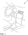
- the operating device 6 comprises a display device 1 with a display surface 2, which is arranged in the interior of the vehicle 11 such that it is clearly visible to at least one vehicle occupant, in particular the driver.
- the display surface 2 can be provided by any type of display, in particular a liquid crystal display.
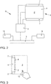
- the operating device 6 further comprises a control device 3 and an input device 4.
- the control device 3 is connected to the display device 1, with which graphic data for displaying information on the display surface 2 can be generated.
- the input device is designed as a touch-sensitive surface 4 on the display surface 2. A so-called touchscreen is thus provided.
- a film can be arranged over the display surface 2, with which the position of a touch of an actuating object 12 can be detected.
- the actuation object is in particular the fingertip of a user.
- the film can e.g. B. as a resistive touch foil, capacitive touch foil or piezoelectric foil.
- the film can be designed so that a heat flow, the z. B. starting from the fingertip 12 of a user is measured. From the temporal development of the touch of the Various inputs can be obtained from the foil. For example, in the simplest case, touching the film at a specific position can be detected and assigned to a graphic object displayed on the display surface 2. Furthermore, the length of the touch can be recorded at a specific position or within a specific area.
- An actuatable button can be displayed on the display surface 2.
- the operating device 6 comprises a proximity detection device 7.
- An actuation object 12 can be detected in a detection area 8 by means of the proximity detection device 7.
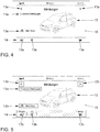
- the detection area 8 is in Fig. 3 presented in detail.
- the detection area 8 is formed in such a way that an approach of an actuation object 12 to the touch-sensitive surface 4 on the display surface 2 is detected.
- the detection area 8 forms at least one volume in front of the user interface 4.
- a cuboid is formed which completely encloses the touch-sensitive surface 4 with its side surfaces in the extension, which runs parallel to the touch-sensitive surface 4.
- the cuboid extends from the touch-sensitive surface 4 or immediately in front of the touch-sensitive surface 4 to a distance of e.g. B. about 40 cm.
- the distance of the outer boundary of the detection area 8 in front of the touch-sensitive surface 4 is chosen so that an approach to the touch-sensitive surface 4 can be detected in time so that the display on the display surface 2 can be changed early enough for the user to be able to Support input.
- the distance of the detection area 8 from the touch-sensitive surface 4 should be selected such that the actuation object 12 or another object is moved into the detection area 8 as rarely as possible if no operation of the touch-sensitive surface 4 is intended.
- the proximity detection device 7 continuously transmits the current position of an actuating object 12 in the detection area 8 to the control device 3. Depending on this signal, the control device 3 can change its state and the display on the display surface 2.
- control device 3 is coupled to a data bus 5. Via this data bus 5, the control device 3 is connected to further devices 9, 10 of the vehicle 11, about which information is to be displayed on the display surface 2 and which are to be operated by means of the operating device 6. Information can be displayed to the vehicle occupants by means of the operating device 6 and by the method. Furthermore, the vehicle occupants can operate devices 9, 10 of the vehicle 11 and control the display by means of the operating device 6.
- FIG. 4 An example of a display on the display surface 2 is shown in the display state. Messages regarding the operating status of the vehicle are displayed. For this purpose, a graphic object 15 is shown, which represents a vehicle. Furthermore, various display elements 13a are displayed, some of which are arranged in a lower bar 14. The display elements 13a indicate, for example, the number of messages present. In addition, symbols are shown which indicate a change between displays for these messages.
- control device 3 automatically changes the display on the display surface 2 to an operating state.
- the display in this operating state is in Fig. 5 reproduced.
- buttons 13b When changing from the display state to the operating state, the display type of the display elements 13a changes to a display type for buttons 13b.
- the position of the buttons 13b in the operating state corresponds to the position of the assigned display elements 13a in the display state.
- the buttons 13b can also be displayed in a different color, with a different brightness, with a different contrast and / or with a different gray level.
- the buttons 13b of the bar 14 are not only shown outlined, but also shown with a different gray level.
- the additional information area 16 which u. a. the graphic object 15 for representing the vehicle, however, remains unchanged when changing from the display state to the operating state.
- the additional information area 16 essentially comprises the entire area of the display area 2 outside the display elements 13a or the display elements 13b. Only in the case of the status information on the mobile radio reception, the current time and the current temperature displayed in the upper area of the display area 2 can a change in the display possibly result if the corresponding status information changes during the change from the display state to the operating state.
- the user can now operate one of the buttons 13b by touching or tapping.
- a corresponding signal is then transmitted to the control device 3.
- the control device 3 then converts this control signal.
- the control device 3 then automatically changes back to the display state, ie after actuation of one of the buttons 13b.
- the control device 3 only changes back to the display state when the actuation object 12 has left the detection space 8 again.
Landscapes
- Engineering & Computer Science (AREA)
- Chemical & Material Sciences (AREA)
- Combustion & Propulsion (AREA)
- Transportation (AREA)
- Mechanical Engineering (AREA)
- User Interface Of Digital Computer (AREA)
- Instrument Panels (AREA)
Description
Die vorliegende Erfindung betrifft ein Verfahren zum Bereitstellen einer Bedienvorrichtung in einem Fahrzeug. Bei dem Verfahren werden von einer Steuervorrichtung Graphikdaten erzeugt, die eine Anzeigefläche so ansteuern, dass in einem Bedienzustand Schaltflächen dargestellt werden, die einem mittels der Eingabeeinrichtung ausführbaren Bedienschritt zugeordnet sind und in einem Anzeigezustand den Schaltflächen zugeordnete Anzeigeelemente dargestellt werden, die keinem mittels der Eingabeeinrichtung ausführbaren Bedienschritt zugeordnet sind. Ferner werden im Anzeige- und Bedienzustand separat von den Anzeigeelementen und Schaltflächen Zusatzinformationen dargestellt.The present invention relates to a method for providing an operating device in a vehicle. In the method, graphic data are generated by a control device, which control a display area in such a way that, in an operating state, buttons are shown that are assigned to an operating step that can be carried out by means of the input device, and display elements that are assigned to the buttons in a display state that none can be carried out by means of the input device Operating step are assigned. Furthermore, additional information is shown separately from the display elements and buttons in the display and operating status.
Des Weiteren betrifft die Erfindung eine Bedienvorrichtung für ein Fahrzeug. Die Bedienvorrichtung umfasst eine Eingabeeinrichtung und eine Anzeigevorrichtung mit einer Anzeigefläche. Die Bedienvorrichtung umfasst ferner eine Annäherungserfassungseinrichtung zum Erfassen der Position eines Betätigungsobjekts vor oder auf der Anzeigefläche und eine Steuervorrichtung, die mit der Eingabeeinrichtung und der Anzeigevorrichtung gekoppelt ist. Mittels der Steuervorrichtung sind Graphikdaten erzeugbar, welche die Anzeigefläche so ansteuern, dass in einem Bedienzustand Schaltflächen dargestellt werden, die einem mittels der Eingabeeinrichtung ausführbaren Bedienschritt zugeordnet sind, und in einem Anzeigezustand den Schaltflächen zugeordnete Anzeigeelemente dargestellt werden, die keinem mittels der Eingabeeinrichtung ausführbaren Bedienschritt zugeordnet sind. Im Anzeige- und Bedienzustand werden außerdem separat von den Anzeigeelementen und Schaltflächen Zusatzinformationen dargestellt. Bei einer Annäherung eines Betätigungsobjekts an die Eingabeeinrichtung wechselt die Steuervorrichtung von dem Anzeigezustand in den Bedienzustand.Furthermore, the invention relates to an operating device for a vehicle. The operating device comprises an input device and a display device with a display surface. The operating device further comprises a proximity detection device for detecting the position of an actuating object in front of or on the display surface and a control device which is coupled to the input device and the display device. The control device can be used to generate graphic data which actuate the display area in such a way that, in an operating state, buttons are shown which are assigned to an operating step which can be carried out by means of the input device, and in a display state which are assigned display elements which are assigned to the buttons and which are not assigned to any operating step which can be carried out by means of the input device are. In the display and operating status, additional information is also displayed separately from the display elements and buttons. When an actuating object approaches the input device, the control device changes from the display state to the operating state.
Mit der Zunahme elektronischer Einrichtungen im Fahrzeug wurde es erforderlich, eine größere Informationsmenge im Fahrzeug darzustellen. Moderne Fahrzeuge umfassen beispielsweise neben einer Multifunktionsanzeige eine Vielzahl von Fahrerassistenzsystemen, deren Informationen im Fahrzeug angezeigt werden müssen. Des Weiteren umfassen Fahrzeuge häufig ein Navigationssystem. Mittels eines solchen Navigationssystems können digitale geographische Straßenkarten mit einer Route und gegebenenfalls vielfältigen Zusatzinformationen angezeigt werden. Schließlich umfassen moderne Fahrzeuge vielfach Kommunikations- und Multimediaanwendungen, einschließlich einer Mobiltelefonschnittstelle und Einrichtungen zur Wiedergabe von Musik und Sprache. Auch für diese Anwendungen muss in dem Fahrzeug die Möglichkeit bestehen, Informationen anzuzeigen.With the increase in electronic devices in the vehicle, it became necessary to display a larger amount of information in the vehicle. For example, in addition to a multifunction display, modern vehicles include a large number of driver assistance systems, the information of which must be displayed in the vehicle. Furthermore, vehicles often include a navigation system. Such a navigation system can be used to display digital geographical road maps with a route and, if appropriate, a variety of additional information. Finally, modern vehicles often include communications and multimedia applications, including a cell phone interface and facilities for Play music and speech. For these applications, too, the vehicle must be able to display information.
Um die vielfältigen Informationen flexibel anzeigen zu können, werden z. B. frei programmierbare Displays eingesetzt, die häufig auch die Wiedergabe herkömmlicher mechanischer Instrumente übernehmen. In der
Zusätzlich zu dem Kombiinstrument wird vielfach eine Anzeigevorrichtung oberhalb der Mittelkonsole des Fahrzeugs angeordnet, über welche weitere Informationen angezeigt werden können. Diese Anzeigevorrichtung wird insbesondere als Multifunktionsanzeige und zur Darstellung einer geographischen Karte eines Navigationssystems verwendet. Eine solche Multifunktionsanzeige ist beispielsweise in der
Damit der Nutzer die auf einer Anzeigefläche dargestellte Information so schnell und intuitiv wie möglich erfassen kann und um ihm außerdem eine schnelle, intuitive und einfache Bedienung von Einrichtungen zu ermöglichen, deren Informationen dargestellt werden, ist aus der
Des Weiteren ist aus der
Aus der
Für die Anzeige von Information in einem Fahrzeug ergeben sich sehr spezielle Anforderungen. Die Informationsaufnahme erfolgt im Fahrzeug unter anderem durch den Fahrer. Die Informationen sollten somit im Fahrzeug so dargestellt werden, dass die Informationsaufnahme durch den Fahrer nicht zu einer Ablenkung während der Fahrt führt. Die dargestellten Informationen sollten daher intuitiv und schnell vom Fahrer erfassbar sein, so dass er für die Informationsaufnahme nur sehr kurzzeitig den Blick vom Fahrgeschehen abwenden muss. Wird die Bedienung der Fahrzeugeinrichtungen von einer Anzeige unterstützt oder geführt, sollte die Anzeige so erfolgen, dass der Fahrer für die Bedienung nur sehr kurz die Anzeige betrachten muss, um die Bedienung durchzuführen.There are very special requirements for displaying information in a vehicle. The driver records the information in the vehicle. The information should therefore be displayed in the vehicle in such a way that the driver's information acquisition does not lead to distraction while driving. The information presented should therefore be intuitively and quickly ascertainable by the driver, so that he only has to take his eyes off the driving situation for a very short time in order to record the information. If the operation of the vehicle equipment is supported or guided by a display, the display should be such that the driver only has to look at the display very briefly in order to perform the operation.
Aus der
Der vorliegenden Erfindung liegt die Aufgabe zugrunde, ein Verfahren und eine Bedienvorrichtung der eingangs genannten Art bereitzustellen, bei welchen die dargestellten Informationen so schnell und intuitiv wie möglich vom Betrachter erfassbar sind und welche eine schnelle, intuitive und einfache Bedienung von Fahrzeugeinrichtungen ermöglichen, deren Informationen dargestellt werden.The present invention has for its object to provide a method and an operating device of the type mentioned, in which the information displayed can be as quickly and intuitively as possible by the viewer and which allow quick, intuitive and easy operation of vehicle devices whose information is displayed become.
Erfindungsgemäß wird diese Aufgabe durch ein Verfahren mit den Merkmalen des Anspruchs 1 und eine Bedienvorrichtung mit den Merkmalen des Anspruchs 6 gelöst. Vorteilhafte Ausgestaltungen und Weiterbildungen ergeben sich aus den abhängigen Ansprüchen.According to the invention, this object is achieved by a method with the features of
Bei dem erfindungsgemäßen Verfahren wechselt die Steuervorrichtung nach der Betätigung einer Schaltfläche automatisch vom Bedienzustand in den Anzeigezustand.In the method according to the invention, the control device automatically changes from the operating state to the display state after the actuation of a button.
Unter einer Schaltfläche wird im Sinne der Erfindung ein Steuerelement einer graphischen Benutzerschnittstelle verstanden. Eine Schaltfläche unterscheidet sich von Elementen und Flächen zur reinen Informationsanzeige, so genannten Anzeigeelementen, darin, dass sie auswählbar sind. Bei einer Auswahl einer Schaltfläche wird eine ihr zugeordnete Funktion ausgeführt. Die Funktion kann nur zu einer Veränderung der Informationsanzeige führen. Ferner können über die Schaltflächen Einrichtungen gesteuert werden, deren Bedienung von der Informationsanzeige unterstützt wird. Die Schaltflächen können somit herkömmliche mechanische Schalter ersetzen. Die Schaltflächen können beliebig für eine frei programmierbaren Anzeigefläche erzeugt und von dieser angezeigt werden. Des Weiteren kann vorgesehen sein, dass eine Schaltfläche markiert werden kann. In diesem Fall wird die zugeordnete Funktion noch nicht ausgeführt. Die markierte Schaltfläche wird jedoch gegenüber anderen Schaltflächen hervorgehoben dargestellt. Erst bei einer Auswahl der Schaltfläche wird die ihr zugeordnete Funktion ausgeführt.For the purposes of the invention, a button is understood to mean a control element of a graphical user interface. A button differs from elements and areas for pure information display, so-called display elements, in that they can be selected. When a button is selected, a function assigned to it is carried out. The function can only change the information display. The buttons can also be used to control devices whose operation is supported by the information display. The buttons can thus replace conventional mechanical switches. The buttons can be created for and displayed by a freely programmable display area. Furthermore, it can be provided that a button can be marked. In this case, the assigned function is not yet carried out. However, the marked button is highlighted compared to other buttons. The function assigned to it is only executed when the button is selected.
Bei dem Betätigungsobjekt, welches bei dem erfindungsgemäßen Verfahren verwendet wird, kann es sich beispielsweise um die Fingerspitze eines Nutzers oder einen Betätigungsstift handeln. Bei dem erfindungsgemäßen Verfahren wird insbesondere eine Anzeigefläche eingesetzt, auf welcher eine berührungsempfindliche Oberfläche ausgebildet ist. Es wird somit ein sogenannter Touchscreen verwendet.The actuating object which is used in the method according to the invention can be, for example, the fingertip of a user or an actuating pen. In the method according to the invention, in particular a display surface is used, on which a touch-sensitive surface is formed. A so-called touchscreen is therefore used.
Bei dem erfindungsgemäßen Verfahren werden im Anzeigezustand die Informationen so dargestellt, dass sie vom Nutzer besonders einfach visuell erfasst werden können. Im Bedienzustand wird die Anzeige dann so verändert, dass der Betrachter zum einen erkennen kann, welche Bereiche der Anzeigefläche als Schaltflächen für die Bedienung ausgebildet sind. Zum anderen kann die Art der Darstellung an die Bedienung einer berührungsempfindlichen Oberfläche auf der Anzeigefläche optimiert werden, indem sich Anzeigeelemente in Schaltflächen umwandeln und dabei anders dargestellt werden.In the method according to the invention, the information is shown in the display state in such a way that it can be visually detected particularly easily by the user. In the operating state, the display is then changed so that on the one hand the viewer can recognize which areas of the display area are designed as buttons for the operation. On the other hand, the type of display for the operation of a touch-sensitive surface on the display surface can be optimized by converting display elements into buttons and displaying them differently.
Will der Nutzer einen Bedienschritt ausführen, braucht er sich nur mit dem Betätigungsobjekt, d.h. zum Beispiel seiner Fingerspitze, der Anzeigefläche annähern. Dies ist eine für den Nutzer intuitive Vorgehensweise, so dass sie zumeist auch vom Fahrer des Fahrzeugs ausgeführt werden kann, ohne dass dieser den Blick vom Fahrgeschehen abwenden muss. Wird eine solche Annäherung an die Anzeigefläche detektiert, wechselt die Steuervorrichtung von dem Anzeigezustand in den Bedienzustand. Wenn der Nutzer nun seinen Blick erst dann kurzfristig auf die Anzeigefläche richtet, nimmt er die Darstellungsart im Bedienzustand wahr und kann auf diese Weise sehr schnell den gewünschten Bedienschritt ausführen. Dabei erleichtert die erfindungsgemäße Umschaltung vom Anzeigezustand in den Bedienzustand es dem Nutzer sich zu orientieren, da die Zusatzinformation außerhalb der Anzeigefläche, den die Anzeigeelemente bzw. Schaltflächen einnehmen, unverändert bleibt.If the user wants to carry out an operating step, he only needs to approach the display area with the actuating object, ie for example his fingertip. This is an intuitive procedure for the user, so that it can usually also be carried out by the driver of the vehicle without having to take his eyes off the driving situation. If such an approach to the display area is detected, the control device changes from the display state to the operating state. If the user only then gazes briefly at the display area, he will perceive the type of display in the operating state and can thus very quickly perform the desired operating step. Thereby facilitates the invention Switching from the display state to the operating state allows the user to orientate himself, since the additional information outside the display area, which the display elements or buttons occupy, remains unchanged.
Gemäß einer bevorzugten Ausgestaltung des erfindungsgemäßen Verfahrens bleibt bei dem Wechsel von dem Anzeigezustand in den Bedienzustand die Darstellung auf der gesamten Anzeigefläche, die im Anzeigezustand nicht von den Anzeigeelementen und im Bedienzustand nicht von den Schaltflächen eingenommen ist, unverändert. Die Anzeigeelemente im Anzeigezustand werden insbesondere in denselben Bereich der Anzeigefläche angezeigt, wie die zugeordneten Schaltflächen im Bedienmodus. Es findet somit nur eine Umwandlung von Anzeigeelementen in Schaltflächen statt, ohne dass sich andere Objekte der Anzeige verändern.According to a preferred embodiment of the method according to the invention, when changing from the display state to the operating state, the display on the entire display area, which is not occupied by the display elements in the display state and not by the buttons in the operating state, remains unchanged. The display elements in the display state are displayed in particular in the same area of the display area as the assigned buttons in the operating mode. There is therefore only a conversion of display elements into buttons without changing other objects on the display.
Gemäß einer Ausgestaltung des erfindungsgemäßen Verfahrens werden bei dem Wechsel von dem Anzeigezustand in den Bedienzustand die Anzeigeelemente zur Darstellung als Schaltfläche mit einer anderen Helligkeit, mit einem anderen Kontrast, in einer anderen Farbe und/oder mit einer anderen Graustufe dargestellt. Des Weiteren können bei dem Wechsel von dem Anzeigezustand in den Bedienzustand die Anzeigeelemente zur Darstellung als Schaltfläche mit einer Umrandung versehen werden. Die Darstellung der Zusatzinformation bleibt hingegen bei diesem Wechsel vom Anzeigezustand in den Bedienzustand unverändert. Unter Zusatzinformation wird insbesondere der gesamte Anzeigeinhalt der Anzeigefläche außerhalb der Anzeigeelemente, die in Schaltflächen umgewandelt werden, verstanden.According to one embodiment of the method according to the invention, when changing from the display state to the operating state, the display elements are displayed as a button with a different brightness, with a different contrast, in a different color and / or with a different gray level. Furthermore, when changing from the display state to the operating state, the display elements can be provided with a border for display as a button. The display of the additional information, however, remains unchanged when changing from the display state to the operating state. Additional information is understood in particular to mean the entire display content of the display area outside the display elements, which are converted into buttons.
Hierdurch wird erreicht, dass der Nutzer sich schnell und intuitiv bei dem Übergang vom Anzeigezustand in den Bedienzustand orientieren kann, gleichzeitig jedoch sehr einfach und schnell erfassen kann, bei welchen graphischen Objekten es sich um betätigbare Schaltflächen handelt.This ensures that the user can quickly and intuitively orient himself during the transition from the display state to the operating state, but at the same time can very easily and quickly grasp which graphic objects are actuatable buttons.
Die erfindungsgemäße Bedienvorrichtung ist dadurch gekennzeichnet, dass bei dem Wechsel von dem Anzeigezustand in den Bedienzustand mittels der Steuervorrichtung Grafikdaten erzeugbar sind, welche die Anzeigefläche so ansteuern, dass die Darstellungsart der Anzeigeelemente in eine Darstellungsart der Schaltflächen wechselt, die Darstellung der Zusatzinformation hingegen unverändert bleibt.The control device according to the invention is characterized in that when changing from the display state to the control state, graphic data can be generated by the control device, which control the display surface in such a way that the display elements change to a display type of the buttons, but the display of the additional information remains unchanged.
Die erfindungsgemäße Bedienvorrichtung ist insbesondere so ausgebildet, dass sie die vorstehend genannten Verfahrensschritte teilweise oder vollständig ausführen kann. Mittels der Bedienvorrichtung können verschiedene Einrichtungen des Fahrzeugs bedient werden. Die erfindungsgemäße Bedienvorrichtung weist dieselben vorstehend genannten Vorteile wie das erfindungsgemäße Verfahren auf.The operating device according to the invention is in particular designed in such a way that it can partially or completely carry out the aforementioned method steps. Various devices of the vehicle can be operated by means of the operating device. The invention Operating device has the same advantages mentioned above as the method according to the invention.
Gemäß einer Ausgestaltung der erfindungsgemäßen Bedienvorrichtung ist auf der Anzeigefläche eine berührungsempfindliche Oberfläche ausgebildet. In diesem Fall wird die Berührung einer auf der Anzeigefläche angezeigten Schaltfläche erfasst und als Betätigung der Schaltfläche interpretiert.According to one embodiment of the operating device according to the invention, a touch-sensitive surface is formed on the display surface. In this case, the touch of a button displayed on the display area is detected and interpreted as actuation of the button.
Des Weiteren wird bei einer Ausgestaltung der erfindungsgemäßen Bedienvorrichtung eine Annäherung des Betätigungsobjekts an die Anzeigefläche erfasst. Die hierfür vorgesehene Annäherungserfassungseinrichtung kann beispielsweise eine Reflektionslichtschranke umfassen, die mindestens ein Leuchtmittel zum Emittieren von elektromagnetischer Detektionsstrahlung in den Detektionsbereich und ein Empfangselement zum Detektieren eines an dem Betätigungsobjekt gestreuten und/oder reflektierten Anteils der Detektionsstrahlung umfassen. Sie kann insbesondere so ausgebildet sein, das Betätigungsobjekt in dem Detektionsbereich anhand der Intensität der empfangenen Detektionsstrahlung zu erkennen. Die Annäherungserfassungseinrichtung kann ferner verschiedene Leuchtmittel für die einzelnen Detektionszonen umfassen, die jeweils elektromagnetische Detektionsstrahlung in die jeweilige Detektionszone emittieren. Ferner kann eine Modulationsvorrichtung zum Modulieren der emittierten Detektionsstrahlung vorgesehen sein, so dass sich die Detektionsstrahlung, die in die einzelnen Detektionszonen emittiert wird, jeweils hinsichtlich ihrer Modulation unterscheidet. In diesem Fall kann die Annäherungserfassungseinrichtung auch eine Analyseeinheit umfassen, die so ausgebildet ist, dass die empfangene reflektierte und/oder gestreute Detektionsstrahlung hinsichtlich ihrer Modulation analysiert werden kann, um zu ermitteln, in welcher Detektionszone die Detektionsstrahlung an einem Betätigungsobjekt gestreut oder reflektiert wurde.Furthermore, in an embodiment of the operating device according to the invention, an approach of the actuating object to the display area is detected. The proximity detection device provided for this purpose can comprise, for example, a reflection light barrier which comprises at least one illuminant for emitting electromagnetic detection radiation into the detection area and a receiving element for detecting a portion of the detection radiation which is scattered and / or reflected on the actuating object. In particular, it can be designed to recognize the actuation object in the detection area on the basis of the intensity of the detection radiation received. The proximity detection device can further comprise different illuminants for the individual detection zones, each of which emits electromagnetic detection radiation into the respective detection zone. Furthermore, a modulation device can be provided for modulating the emitted detection radiation, so that the detection radiation that is emitted into the individual detection zones differs in terms of its modulation. In this case, the proximity detection device can also comprise an analysis unit which is designed such that the received reflected and / or scattered detection radiation can be analyzed with regard to its modulation in order to determine in which detection zone the detection radiation was scattered or reflected on an actuating object.
Des Weiteren betrifft die Erfindung ein Fahrzeug mit der erfindungsgemäßen Bedienvorrichtung. Die Anzeigefläche ist in diesem Fall so angeordnet, dass sie gut von dem Fahrer und/oder dem Beifahrer erreicht werden kann. Beispielsweise ist die Anzeigefläche in der Mittelkonsole des Fahrzeugs angeordnet.Furthermore, the invention relates to a vehicle with the operating device according to the invention. In this case, the display area is arranged in such a way that it can be easily reached by the driver and / or the passenger. For example, the display area is arranged in the center console of the vehicle.
Die Erfindung wird nun anhand eines Ausführungsbeispiels mit Bezug zu den Zeichnungen erläutert.
Figur 1- zeigt ein Fahrzeug mit dem Ausführungsbeispiel einer erfindungsgemäßen Bedienvorrichtung,
Figur 2- zeigt den Aufbau der erfindungsgemäßen Bedienvorrichtung zum Ausführen des erfindungsgemäßen Verfahrens und die Verbindung dieser Bedienvorrichtung mit anderen Einrichtungen des Fahrzeugs,
Figur 3- zeigt eine Schnittansicht der Anzeigevorrichtung der Bedienvorrichtung,
Figur 4- zeigt eine Anzeige im Anzeigezustand auf der Anzeigefläche der Bedienvorrichtung, die von einem Ausführungsbeispiel des erfindungsgemäßen Verfahrens erzeugt wurden, und
Figur 5- zeigt eine Anzeige im Bedienzustand auf der Anzeigefläche der Bedienvorrichtung, die von einem Ausführungsbeispiel des erfindungsgemäßen Verfahrens erzeugt wurden.
- Figure 1
- shows a vehicle with the embodiment of an operating device according to the invention,
- Figure 2
- shows the structure of the control device according to the invention for executing the method according to the invention and the connection of this control device with other devices of the vehicle,
- Figure 3
- shows a sectional view of the display device of the operating device,
- Figure 4
- shows a display in the display state on the display surface of the operating device, which were generated by an embodiment of the inventive method, and
- Figure 5
- shows a display in the operating state on the display surface of the operating device, which were generated by an embodiment of the inventive method.
Mit Bezug zu den
Die Bedienvorrichtung 6 umfasst eine Anzeigevorrichtung 1 mit einer Anzeigefläche 2, die so im Innenraum des Fahrzeugs 11 angeordnet ist, dass sie für zumindest einen Fahrzeuginsassen, insbesondere den Fahrer, gut sichtbar ist. Die Anzeigefläche 2 kann von einem Display, insbesondere einem Flüssigkeitskristalldisplay, beliebiger Bauart bereitgestellt werden.With reference to the
The operating
Die Bedienvorrichtung 6 umfasst ferner eine Steuervorrichtung 3 und eine Eingabevorrichtung 4. Die Steuervorrichtung 3 ist mit der Anzeigevorrichtung 1 verbunden, mit welcher Graphikdaten zur Informationsdarstellung auf der Anzeigefläche 2 erzeugbar sind. Die Eingabevorrichtung ist als berührungsempfindliche Oberfläche 4 auf der Anzeigefläche 2 ausgebildet. Es wird somit ein sogenannter Touchscreen bereitgestellt.The operating
Beispielsweise kann eine Folie über der Anzeigefläche 2 angeordnet sein, mit welcher die Position einer Berührung eines Betätigungsobjekts 12 detektiert werden kann. Bei dem Betätigungsobjekt handelt es sich insbesondere um die Fingerspitze eines Nutzers. Die Folie kann z. B. als resistive Touchfolie, kapazitive Touchfolie oder piezoelektrische Folie ausgebildet sein. Ferner kann die Folie so ausgebildet sein, dass ein Wärmestrom, der z. B. von der Fingerspitze 12 eines Nutzers ausgeht, gemessen wird. Aus der zeitlichen Entwicklung der Berührung der Folie lassen sich verschiedene Eingaben gewinnen. Beispielsweise kann im einfachsten Fall das Berühren der Folie bei einer bestimmten Position erfasst und einem auf der Anzeigefläche 2 angezeigten graphischen Objekt zugeordnet werden. Des Weiteren kann die Länge der Berührung bei einer bestimmten Position oder innerhalb eines bestimmten Bereichs erfasst werden. Auf der Anzeigefläche 2 kann eine betätigbare Schaltfläche angezeigt werden.For example, a film can be arranged over the
Des Weiteren umfasst die Bedienvorrichtung 6 eine Annäherungserfassungseinrichtung 7. Mittels der Annäherungserfassungseinrichtung 7 kann ein Betätigungsobjekt 12 in einem Detektionsbereich 8 erfasst werden. Der Detektionsbereich 8 ist in
In dem hier beschriebenen Ausführungsbeispiel bildet der Detektionsbereich 8 zumindest ein Volumen vor der Bedienoberfläche 4. Es ist insbesondere ein Quader gebildet, der mit seinen Seitenflächen in der Erstreckung, die parallel zu der berührungsempfindlichen Oberfläche 4 verläuft, die berührungsempfindliche Oberfläche 4 vollständig umschließt. In einer Richtung senkrecht zur berührungsempfindlichen Oberfläche 4 reicht der Quader von der berührungsempfindlichen Oberfläche 4 oder unmittelbar vor der berührungsempfindlichen Oberfläche 4 bis zu einem Abstand von z. B. etwa 40 cm. Der Abstand der äußeren Grenze des Detektionsbereichs 8 vor der berührungsempfindlichen Oberfläche 4 wird dabei so gewählt, dass eine Annäherung an die berührungsempfindliche Oberfläche 4 so rechtzeitig detektiert werden kann, dass die Anzeige auf der Anzeigefläche 2 früh genug verändert werden kann, um den Nutzer bei einer Eingabe zu unterstützen. Ferner sollte der Abstand des Detektionsbereichs 8 von der berührungsempfindlichen Oberfläche 4 so gewählt werden, dass das Betätigungsobjekt 12 oder ein anderes Objekt so selten wie möglich in den Detektionsbereich 8 bewegt wird, wenn keine Bedienung der berührungsempfindlichen Oberfläche 4 beabsichtigt ist.In the exemplary embodiment described here, the
Weitere Details zu verschiedenen Ausbildungen der Annäherungserfassungseinrichtung 7 sind beispielsweise in der
Die Annäherungserfassungseinrichtung 7 überträgt die aktuelle Position eines Betätigungsobjekts 12 im Detektionsbereich 8 fortwährend an die Steuervorrichtung 3. In Abhängigkeit von diesem Signal kann die Steuervorrichtung 3 ihren Zustand und die Anzeige auf der Anzeigefläche 2 verändern.The
Schließlich ist die Steuervorrichtung 3 mit einem Datenbus 5 gekoppelt. Über diesen Datenbus 5 ist die Steuervorrichtung 3 mit weiteren Einrichtungen 9, 10 des Fahrzeugs 11 verbunden, zu denen Informationen auf der Anzeigefläche 2 angezeigt werden sollen und die mittels der Bedienvorrichtung 6 bedient werden sollen. Mittels Bedienvorrichtung 6 und durch das Verfahren können den Fahrzeuginsassen Informationen angezeigt werden. Ferner können die Fahrzeuginsassen mittels der Bedienvorrichtung 6 Einrichtungen 9, 10 des Fahrzeugs 11 bedienen und die Anzeige steuern.Finally, the
Im Folgenden wird ein Ausführungsbeispiel des erfindungsgemäßen Verfahrens, welches von der vorstehend beschriebenen Bedienvorrichtung 6 ausführbar ist, mit Bezug zu den
In
In
Wenn sich der Nutzer nun mit seiner Fingerspitze 12 der berührungsempfindlichen Oberfläche 4 auf der Anzeigefläche 2 nähert und in den Detektionsbereich 8 eintritt, wechselt die Steuervorrichtung 3 die Anzeige auf der Anzeigefläche 2 automatisch in einen Bedienzustand. Die Anzeige in diesem Bedienzustand ist in
Beim Wechsel von dem Anzeigezustand in den Bedienzustand wechselt die Darstellungsart der Anzeigeelemente 13a in eine Darstellungsart für Schaltflächen 13b. Die Position der Schaltflächen 13b im Bedienzustand entspricht dabei der Position der zugeordneten Anzeigeelemente 13a im Anzeigezustand. Um darauf hinzuweisen, dass es sich bei den Anzeigeelementen 13a nun um Schaltflächen 13b handelt, welche durch Berührung der berührungsempfindlichen Oberfläche 4 bei der entsprechenden Position betätigt werden können, ist bei den Schaltflächen 13b eine Umrandung vorgesehen. Alternativ oder zusätzlich können die Schaltflächen auch in einer anderen Farbe, mit einer anderen Helligkeit, mit einem anderen Kontrast und/oder mit einer anderen Graustufe dargestellt werden. In dem in
Die Zusatzinformationsfläche 16, die u. a. das grafische Objekt 15 zur Darstellung des Fahrzeugs umfasst, bleibt beim Wechsel von dem Anzeigezustand in den Bedienzustand hingegen unverändert. Die Zusatzinformationsfläche 16 umfasst im Wesentlichen die gesamte Fläche der Anzeigefläche 2 außerhalb der Anzeigeelemente 13a bzw. der Anzeigeelemente 13b. Nur bei den im oberen Bereich der Anzeigefläche 2 angezeigten Statusinformationen zu dem Mobilfunkempfang, der aktuellen Uhrzeit und der aktuellen Temperatur, kann sich möglicherweise eine Veränderung der Anzeige ergeben, wenn sich die entsprechenden Statusinformationen während des Wechsels von dem Anzeigezustand in den Bedienzustand ändern.The
Der Nutzer kann nun durch Berühren bzw. Antippen eine der Schaltflächen 13b betätigen. Der Steuervorrichtung 3 wird daraufhin ein entsprechendes Signal übertragen. Die Steuervorrichtung 3 setzt dieses Steuersignal dann um. Gemäß einer Ausbildung des erfindungsgemäßen Verfahrens wechselt die Steuervorrichtung 3 daraufhin, d. h. nach der Betätigung einer der Schaltflächen 13b, automatisch zurück in den Anzeigezustand. Gemäß einer anderen Ausgestaltung des erfindungsgemäßen Verfahrens wechselt die Steuervorrichtung 3 erst dann in den Anzeigezustand zurück, wenn das Betätigungsobjekt 12 den Detektionsraum 8 wieder verlassen hat.The user can now operate one of the
- 11
- AnzeigevorrichtungDisplay device
- 22nd
- AnzeigeflächeDisplay area
- 33rd
- SteuervorrichtungControl device
- 44th
- berührungsempfindliche Oberfläche, Eingabevorrichtungtouch-sensitive surface, input device
- 55
- DatenbusData bus
- 66
- BedienvorrichtungOperating device
- 77
- AnnäherungserfassungseinrichtungProximity detection device
- 88th
- DetektionsbereichDetection range
- 99
- Einrichtung des FahrzeugsSet up the vehicle
- 1010th
- Einrichtung des FahrzeugsSet up the vehicle
- 1111
- Fahrzeugvehicle
- 1212
- Betätigungsobjekt, FingerspitzeActuating object, fingertip
- 13a13a
- graphisches Anzeigeelementgraphic display element
- 13b13b
- Schaltflächebutton
- 1414
- Leistestrip
- 1515
- graphisches Objektgraphic object
- 1616
- ZusatzinformationsflächeAdditional information area
Claims (7)
- Method for providing an operating apparatus (6) in a vehicle (11), in which- a control apparatus (3) generates graphics data which control a display surface (2) in such a manner that- buttons (13b) which are assigned to an operating step which can be carried out by means of the input device (4) are displayed in an operating state,- display elements (13a) which are assigned to the buttons (13b) and are not assigned to an operating step which can be carried out by means of the input device (4) are displayed in a display state, and- additional information is displayed in the display and operating states separately from the display elements (13a) and buttons (13b),- it is detected when an object approaches the input device (4), and- if an actuation object (12) approaches the input device (4), the control apparatus (3) changes from the display state to the operating state, and- during the change from the display state to the operating state, the type of display for the display elements (13a) changes to a type of display for the button (13b), but the display of the additional information remains unchanged, characterized in that- the control apparatus (3) automatically changes from the operating state to the display state after the actuation of a button (13b).
- Method according to Claim 1,
characterized
in that, during the change from the display state to the operating state, the display on the entire display surface (2), which is not occupied by the display elements (13b) in the display state and is not occupied by the buttons (13b) in the operating state, remains unchanged. - Method according to Claim 1 or 2,
characterized
in that the display elements (13b) in the display state are displayed in the same region of the display surface (2) as the assigned buttons (13b) in the operating mode. - Method according to one of the preceding claims, characterized
in that, during the change from the display state to the operating state, the display elements (13a) are displayed with a different brightness, with a different contrast, in a different colour and/or with a different greyscale for displaying as a button (13b). - Method according to one of the preceding claims, characterized
in that, during the change from the display state to the operating state, the display elements (13a) are provided with a border for display as a button (13b). - Operating apparatus (6) for a vehicle, having- an input device (4),- a display apparatus (1) with a display surface (2),- an approach capture device (7) for capturing the position of an actuation object in front of or on the display surface (2),- a control apparatus (3) which is coupled to the input device (4) and to the display apparatus (1) and can be used to generate graphics data which control the display surface (2) in such a manner that- buttons (13b) which are assigned to an operating step which can be carried out by means of the input device (4) are displayed in an operating state- display elements (13a) which are assigned to the buttons (13b) and are not assigned to an operating step which can be carried out by means of the input device (4) are displayed in a display state, and- additional information is displayed in the display and operating states separately from the display elements (13a) and buttons (13b), and- wherein, if an actuation object (12) approaches the input device (4), the control apparatus (3) changes from the display state to the operating state, and
during the change from the display state to the operating state, the control apparatus (3) can be used to generate graphics data which control the display surface (2) in such a manner that the type of display for the display elements (13a) changes to a type of display for the buttons (13b), but the display of the additional information remains unchanged,
characterized in that- the control apparatus (3) is configured to automatically change from the operating state to the display state after the actuation of a button (13b) . - Vehicle having an operating apparatus (6) according to Claim 6.
Applications Claiming Priority (2)
| Application Number | Priority Date | Filing Date | Title |
|---|---|---|---|
| DE102012002271A DE102012002271A1 (en) | 2012-02-04 | 2012-02-04 | Method for providing an operating device in a vehicle and operating device for a vehicle |
| PCT/EP2013/051747 WO2013113731A1 (en) | 2012-02-04 | 2013-01-30 | Method for producing an operating device in a vehicle and operating device for a vehicle |
Publications (2)
| Publication Number | Publication Date |
|---|---|
| EP2809541A1 EP2809541A1 (en) | 2014-12-10 |
| EP2809541B1 true EP2809541B1 (en) | 2020-06-24 |
Family
ID=47683709
Family Applications (1)
| Application Number | Title | Priority Date | Filing Date |
|---|---|---|---|
| EP13703552.3A Active EP2809541B1 (en) | 2012-02-04 | 2013-01-30 | Method for producing an operating device in a vehicle and operating device for a vehicle |
Country Status (4)
| Country | Link |
|---|---|
| EP (1) | EP2809541B1 (en) |
| DE (1) | DE102012002271A1 (en) |
| ES (1) | ES2808401T3 (en) |
| WO (1) | WO2013113731A1 (en) |
Families Citing this family (1)
| Publication number | Priority date | Publication date | Assignee | Title |
|---|---|---|---|---|
| DE102013226167A1 (en) * | 2013-12-17 | 2015-06-18 | Lemförder Electronic GmbH | Method and apparatus for placing an electronic display device in a safe state and control device for controlling an electronic display device |
Citations (1)
| Publication number | Priority date | Publication date | Assignee | Title |
|---|---|---|---|---|
| DE102009048043A1 (en) * | 2008-10-15 | 2010-04-22 | Volkswagen Ag | Multifunction display and control system and method for controlling such a system with optimized graphical operator display |
Family Cites Families (7)
| Publication number | Priority date | Publication date | Assignee | Title |
|---|---|---|---|---|
| DE19941956B4 (en) | 1999-09-03 | 2006-12-14 | Volkswagen Ag | Multifunction control with a display |
| DE102006032118B4 (en) | 2006-07-12 | 2022-03-03 | Volkswagen Ag | Instrument cluster for a motor vehicle and motor vehicle |
| DE102007039444A1 (en) | 2007-08-21 | 2009-02-26 | Volkswagen Ag | Method for displaying information in a motor vehicle and display device for a motor vehicle |
| DE102007039445A1 (en) | 2007-08-21 | 2009-02-26 | Volkswagen Ag | Method for displaying information in a motor vehicle for an operating state and a display state and display device |
| DE102007039442A1 (en) | 2007-08-21 | 2009-02-26 | Volkswagen Ag | Method for displaying information in a vehicle and display device for a vehicle |
| DE102009019561A1 (en) * | 2009-04-30 | 2010-11-04 | Volkswagen Ag | Method for displaying information in a motor vehicle and display device |
| DE102009051202A1 (en) | 2009-10-29 | 2011-05-12 | Volkswagen Ag | Method for operating an operating device and operating device |
-
2012
- 2012-02-04 DE DE102012002271A patent/DE102012002271A1/en not_active Withdrawn
-
2013
- 2013-01-30 EP EP13703552.3A patent/EP2809541B1/en active Active
- 2013-01-30 WO PCT/EP2013/051747 patent/WO2013113731A1/en active Application Filing
- 2013-01-30 ES ES13703552T patent/ES2808401T3/en active Active
Patent Citations (1)
| Publication number | Priority date | Publication date | Assignee | Title |
|---|---|---|---|---|
| DE102009048043A1 (en) * | 2008-10-15 | 2010-04-22 | Volkswagen Ag | Multifunction display and control system and method for controlling such a system with optimized graphical operator display |
Also Published As
| Publication number | Publication date |
|---|---|
| EP2809541A1 (en) | 2014-12-10 |
| ES2808401T3 (en) | 2021-02-26 |
| DE102012002271A1 (en) | 2013-08-08 |
| WO2013113731A1 (en) | 2013-08-08 |
Similar Documents
| Publication | Publication Date | Title |
|---|---|---|
| EP2766211B1 (en) | Method for making available an operator control, in particular in a vehicle, and operator control for a vehicle | |
| EP2350799B1 (en) | Method and device for displaying information sorted into lists | |
| EP2150883A1 (en) | Multifunction display and operating device and method for operating a multifunction display and operating device having improved selection operation | |
| EP3114554B1 (en) | Method and apparatus for providing a graphical user interface in a vehicle | |
| EP2485913B1 (en) | Method and display device for displaying information | |
| EP2246214B1 (en) | Method and device for displaying information arranged in lists | |
| EP2766208B1 (en) | Method for displaying information in particular in a vehicle and display unit for a vehicle | |
| DE102010012239B4 (en) | Operating and display device for a motor vehicle | |
| EP2675648B1 (en) | Method and device for displaying operating states of vehicle systems and vehicle equipped with such a device | |
| DE102013000069B4 (en) | Motor vehicle user interface with a control element for detecting a control action | |
| EP2943866B1 (en) | Method and device for providing a user interface in a vehicle | |
| EP2344356A1 (en) | Method and device for displaying information, in particular in a vehicle | |
| EP2809541B1 (en) | Method for producing an operating device in a vehicle and operating device for a vehicle | |
| EP2750916B1 (en) | Method for providing an operating device in a vehicle, and operating device for a vehicle | |
| EP2885153B1 (en) | Method for providing an operating device in a vehicle and operating device for a vehicle | |
| EP2703205B1 (en) | Method for displaying and operating functional groups and/or functions and a display and operating device | |
| DE102013001382A1 (en) | Display system and method for viewing direction dependent operation of a display system | |
| EP2917062B1 (en) | Method for displaying information in a vehicle, and a device for controlling the display | |
| DE102012016110A1 (en) | Method for providing operating device in vehicle e.g. motor car, involves displaying button associated with photographic attachment element according to the activation of button displayed on display surface | |
| EP2107456B1 (en) | Selection of SKINS display modes for an infotainment system | |
| DE102013007329A1 (en) | Method for operating an operating device in a vehicle |
Legal Events
| Date | Code | Title | Description |
|---|---|---|---|
| PUAI | Public reference made under article 153(3) epc to a published international application that has entered the european phase |
Free format text: ORIGINAL CODE: 0009012 |
|
| 17P | Request for examination filed |
Effective date: 20140904 |
|
| AK | Designated contracting states |
Kind code of ref document: A1 Designated state(s): AL AT BE BG CH CY CZ DE DK EE ES FI FR GB GR HR HU IE IS IT LI LT LU LV MC MK MT NL NO PL PT RO RS SE SI SK SM TR |
|
| AX | Request for extension of the european patent |
Extension state: BA ME |
|
| RIN1 | Information on inventor provided before grant (corrected) |
Inventor name: HOFMANN, GUSTAV Inventor name: HAHN, ALEXANDER Inventor name: BUDZYNSKI, TOBIAS Inventor name: PETERSEN, SOENKE Inventor name: KUHN, MATHIAS Inventor name: JUN, MI-RAN |
|
| DAX | Request for extension of the european patent (deleted) | ||
| STAA | Information on the status of an ep patent application or granted ep patent |
Free format text: STATUS: EXAMINATION IS IN PROGRESS |
|
| 17Q | First examination report despatched |
Effective date: 20190522 |
|
| GRAP | Despatch of communication of intention to grant a patent |
Free format text: ORIGINAL CODE: EPIDOSNIGR1 |
|
| STAA | Information on the status of an ep patent application or granted ep patent |
Free format text: STATUS: GRANT OF PATENT IS INTENDED |
|
| INTG | Intention to grant announced |
Effective date: 20200319 |
|
| GRAS | Grant fee paid |
Free format text: ORIGINAL CODE: EPIDOSNIGR3 |
|
| GRAA | (expected) grant |
Free format text: ORIGINAL CODE: 0009210 |
|
| STAA | Information on the status of an ep patent application or granted ep patent |
Free format text: STATUS: THE PATENT HAS BEEN GRANTED |
|
| AK | Designated contracting states |
Kind code of ref document: B1 Designated state(s): AL AT BE BG CH CY CZ DE DK EE ES FI FR GB GR HR HU IE IS IT LI LT LU LV MC MK MT NL NO PL PT RO RS SE SI SK SM TR |
|
| REG | Reference to a national code |
Ref country code: GB Ref legal event code: FG4D Free format text: NOT ENGLISH |
|
| REG | Reference to a national code |
Ref country code: CH Ref legal event code: EP |
|
| REG | Reference to a national code |
Ref country code: DE Ref legal event code: R096 Ref document number: 502013014837 Country of ref document: DE |
|
| REG | Reference to a national code |
Ref country code: AT Ref legal event code: REF Ref document number: 1283551 Country of ref document: AT Kind code of ref document: T Effective date: 20200715 |
|
| REG | Reference to a national code |
Ref country code: IE Ref legal event code: FG4D Free format text: LANGUAGE OF EP DOCUMENT: GERMAN |
|
| PG25 | Lapsed in a contracting state [announced via postgrant information from national office to epo] |
Ref country code: LT Free format text: LAPSE BECAUSE OF FAILURE TO SUBMIT A TRANSLATION OF THE DESCRIPTION OR TO PAY THE FEE WITHIN THE PRESCRIBED TIME-LIMIT Effective date: 20200624 Ref country code: NO Free format text: LAPSE BECAUSE OF FAILURE TO SUBMIT A TRANSLATION OF THE DESCRIPTION OR TO PAY THE FEE WITHIN THE PRESCRIBED TIME-LIMIT Effective date: 20200924 Ref country code: GR Free format text: LAPSE BECAUSE OF FAILURE TO SUBMIT A TRANSLATION OF THE DESCRIPTION OR TO PAY THE FEE WITHIN THE PRESCRIBED TIME-LIMIT Effective date: 20200925 Ref country code: FI Free format text: LAPSE BECAUSE OF FAILURE TO SUBMIT A TRANSLATION OF THE DESCRIPTION OR TO PAY THE FEE WITHIN THE PRESCRIBED TIME-LIMIT Effective date: 20200624 Ref country code: SE Free format text: LAPSE BECAUSE OF FAILURE TO SUBMIT A TRANSLATION OF THE DESCRIPTION OR TO PAY THE FEE WITHIN THE PRESCRIBED TIME-LIMIT Effective date: 20200624 |
|
| REG | Reference to a national code |
Ref country code: LT Ref legal event code: MG4D |
|
| PG25 | Lapsed in a contracting state [announced via postgrant information from national office to epo] |
Ref country code: HR Free format text: LAPSE BECAUSE OF FAILURE TO SUBMIT A TRANSLATION OF THE DESCRIPTION OR TO PAY THE FEE WITHIN THE PRESCRIBED TIME-LIMIT Effective date: 20200624 Ref country code: BG Free format text: LAPSE BECAUSE OF FAILURE TO SUBMIT A TRANSLATION OF THE DESCRIPTION OR TO PAY THE FEE WITHIN THE PRESCRIBED TIME-LIMIT Effective date: 20200924 Ref country code: RS Free format text: LAPSE BECAUSE OF FAILURE TO SUBMIT A TRANSLATION OF THE DESCRIPTION OR TO PAY THE FEE WITHIN THE PRESCRIBED TIME-LIMIT Effective date: 20200624 Ref country code: LV Free format text: LAPSE BECAUSE OF FAILURE TO SUBMIT A TRANSLATION OF THE DESCRIPTION OR TO PAY THE FEE WITHIN THE PRESCRIBED TIME-LIMIT Effective date: 20200624 |
|
| REG | Reference to a national code |
Ref country code: NL Ref legal event code: MP Effective date: 20200624 |
|
| PG25 | Lapsed in a contracting state [announced via postgrant information from national office to epo] |
Ref country code: AL Free format text: LAPSE BECAUSE OF FAILURE TO SUBMIT A TRANSLATION OF THE DESCRIPTION OR TO PAY THE FEE WITHIN THE PRESCRIBED TIME-LIMIT Effective date: 20200624 Ref country code: NL Free format text: LAPSE BECAUSE OF FAILURE TO SUBMIT A TRANSLATION OF THE DESCRIPTION OR TO PAY THE FEE WITHIN THE PRESCRIBED TIME-LIMIT Effective date: 20200624 |
|
| PG25 | Lapsed in a contracting state [announced via postgrant information from national office to epo] |
Ref country code: PT Free format text: LAPSE BECAUSE OF FAILURE TO SUBMIT A TRANSLATION OF THE DESCRIPTION OR TO PAY THE FEE WITHIN THE PRESCRIBED TIME-LIMIT Effective date: 20201026 Ref country code: EE Free format text: LAPSE BECAUSE OF FAILURE TO SUBMIT A TRANSLATION OF THE DESCRIPTION OR TO PAY THE FEE WITHIN THE PRESCRIBED TIME-LIMIT Effective date: 20200624 Ref country code: SM Free format text: LAPSE BECAUSE OF FAILURE TO SUBMIT A TRANSLATION OF THE DESCRIPTION OR TO PAY THE FEE WITHIN THE PRESCRIBED TIME-LIMIT Effective date: 20200624 Ref country code: RO Free format text: LAPSE BECAUSE OF FAILURE TO SUBMIT A TRANSLATION OF THE DESCRIPTION OR TO PAY THE FEE WITHIN THE PRESCRIBED TIME-LIMIT Effective date: 20200624 |
|
| PG25 | Lapsed in a contracting state [announced via postgrant information from national office to epo] |
Ref country code: IS Free format text: LAPSE BECAUSE OF FAILURE TO SUBMIT A TRANSLATION OF THE DESCRIPTION OR TO PAY THE FEE WITHIN THE PRESCRIBED TIME-LIMIT Effective date: 20201024 Ref country code: PL Free format text: LAPSE BECAUSE OF FAILURE TO SUBMIT A TRANSLATION OF THE DESCRIPTION OR TO PAY THE FEE WITHIN THE PRESCRIBED TIME-LIMIT Effective date: 20200624 Ref country code: SK Free format text: LAPSE BECAUSE OF FAILURE TO SUBMIT A TRANSLATION OF THE DESCRIPTION OR TO PAY THE FEE WITHIN THE PRESCRIBED TIME-LIMIT Effective date: 20200624 |
|
| REG | Reference to a national code |
Ref country code: ES Ref legal event code: FG2A Ref document number: 2808401 Country of ref document: ES Kind code of ref document: T3 Effective date: 20210226 |
|
| REG | Reference to a national code |
Ref country code: DE Ref legal event code: R097 Ref document number: 502013014837 Country of ref document: DE |
|
| PG25 | Lapsed in a contracting state [announced via postgrant information from national office to epo] |
Ref country code: DK Free format text: LAPSE BECAUSE OF FAILURE TO SUBMIT A TRANSLATION OF THE DESCRIPTION OR TO PAY THE FEE WITHIN THE PRESCRIBED TIME-LIMIT Effective date: 20200624 |
|
| PLBE | No opposition filed within time limit |
Free format text: ORIGINAL CODE: 0009261 |
|
| STAA | Information on the status of an ep patent application or granted ep patent |
Free format text: STATUS: NO OPPOSITION FILED WITHIN TIME LIMIT |
|
| 26N | No opposition filed |
Effective date: 20210325 |
|
| PG25 | Lapsed in a contracting state [announced via postgrant information from national office to epo] |
Ref country code: SI Free format text: LAPSE BECAUSE OF FAILURE TO SUBMIT A TRANSLATION OF THE DESCRIPTION OR TO PAY THE FEE WITHIN THE PRESCRIBED TIME-LIMIT Effective date: 20200624 Ref country code: MC Free format text: LAPSE BECAUSE OF FAILURE TO SUBMIT A TRANSLATION OF THE DESCRIPTION OR TO PAY THE FEE WITHIN THE PRESCRIBED TIME-LIMIT Effective date: 20200624 |
|
| REG | Reference to a national code |
Ref country code: CH Ref legal event code: PL |
|
| PG25 | Lapsed in a contracting state [announced via postgrant information from national office to epo] |
Ref country code: LU Free format text: LAPSE BECAUSE OF NON-PAYMENT OF DUE FEES Effective date: 20210130 |
|
| REG | Reference to a national code |
Ref country code: BE Ref legal event code: MM Effective date: 20210131 |
|
| PG25 | Lapsed in a contracting state [announced via postgrant information from national office to epo] |
Ref country code: CH Free format text: LAPSE BECAUSE OF NON-PAYMENT OF DUE FEES Effective date: 20210131 Ref country code: LI Free format text: LAPSE BECAUSE OF NON-PAYMENT OF DUE FEES Effective date: 20210131 |
|
| PG25 | Lapsed in a contracting state [announced via postgrant information from national office to epo] |
Ref country code: IE Free format text: LAPSE BECAUSE OF NON-PAYMENT OF DUE FEES Effective date: 20210130 |
|
| REG | Reference to a national code |
Ref country code: AT Ref legal event code: MM01 Ref document number: 1283551 Country of ref document: AT Kind code of ref document: T Effective date: 20210130 |
|
| PG25 | Lapsed in a contracting state [announced via postgrant information from national office to epo] |
Ref country code: AT Free format text: LAPSE BECAUSE OF NON-PAYMENT OF DUE FEES Effective date: 20210130 |
|
| PG25 | Lapsed in a contracting state [announced via postgrant information from national office to epo] |
Ref country code: BE Free format text: LAPSE BECAUSE OF NON-PAYMENT OF DUE FEES Effective date: 20210131 |
|
| PGFP | Annual fee paid to national office [announced via postgrant information from national office to epo] |
Ref country code: FR Payment date: 20230124 Year of fee payment: 11 |
|
| PG25 | Lapsed in a contracting state [announced via postgrant information from national office to epo] |
Ref country code: HU Free format text: LAPSE BECAUSE OF FAILURE TO SUBMIT A TRANSLATION OF THE DESCRIPTION OR TO PAY THE FEE WITHIN THE PRESCRIBED TIME-LIMIT; INVALID AB INITIO Effective date: 20130130 |
|
| PGFP | Annual fee paid to national office [announced via postgrant information from national office to epo] |
Ref country code: IT Payment date: 20230120 Year of fee payment: 11 |
|
| P01 | Opt-out of the competence of the unified patent court (upc) registered |
Effective date: 20230523 |
|
| PG25 | Lapsed in a contracting state [announced via postgrant information from national office to epo] |
Ref country code: CY Free format text: LAPSE BECAUSE OF FAILURE TO SUBMIT A TRANSLATION OF THE DESCRIPTION OR TO PAY THE FEE WITHIN THE PRESCRIBED TIME-LIMIT Effective date: 20200624 |
|
| REG | Reference to a national code |
Ref country code: DE Ref legal event code: R079 Ref document number: 502013014837 Country of ref document: DE Free format text: PREVIOUS MAIN CLASS: B60K0037060000 Ipc: B60K0035100000 |
|
| PGFP | Annual fee paid to national office [announced via postgrant information from national office to epo] |
Ref country code: ES Payment date: 20240213 Year of fee payment: 12 |
|
| PG25 | Lapsed in a contracting state [announced via postgrant information from national office to epo] |
Ref country code: MK Free format text: LAPSE BECAUSE OF FAILURE TO SUBMIT A TRANSLATION OF THE DESCRIPTION OR TO PAY THE FEE WITHIN THE PRESCRIBED TIME-LIMIT Effective date: 20200624 |
|
| PGFP | Annual fee paid to national office [announced via postgrant information from national office to epo] |
Ref country code: DE Payment date: 20240131 Year of fee payment: 12 Ref country code: CZ Payment date: 20240117 Year of fee payment: 12 Ref country code: GB Payment date: 20240123 Year of fee payment: 12 |