EP2807967A1 - Tabletop grill - Google Patents
Tabletop grill Download PDFInfo
- Publication number
- EP2807967A1 EP2807967A1 EP20140170674 EP14170674A EP2807967A1 EP 2807967 A1 EP2807967 A1 EP 2807967A1 EP 20140170674 EP20140170674 EP 20140170674 EP 14170674 A EP14170674 A EP 14170674A EP 2807967 A1 EP2807967 A1 EP 2807967A1
- Authority
- EP
- European Patent Office
- Prior art keywords
- grill
- unit
- heating element
- tabletop
- plate
- Prior art date
- Legal status (The legal status is an assumption and is not a legal conclusion. Google has not performed a legal analysis and makes no representation as to the accuracy of the status listed.)
- Withdrawn
Links
Images


Classifications
-
- A—HUMAN NECESSITIES
- A47—FURNITURE; DOMESTIC ARTICLES OR APPLIANCES; COFFEE MILLS; SPICE MILLS; SUCTION CLEANERS IN GENERAL
- A47J—KITCHEN EQUIPMENT; COFFEE MILLS; SPICE MILLS; APPARATUS FOR MAKING BEVERAGES
- A47J37/00—Baking; Roasting; Grilling; Frying
- A47J37/06—Roasters; Grills; Sandwich grills
- A47J37/0611—Roasters; Grills; Sandwich grills the food being cooked between two heating plates, e.g. waffle-irons
-
- A—HUMAN NECESSITIES
- A47—FURNITURE; DOMESTIC ARTICLES OR APPLIANCES; COFFEE MILLS; SPICE MILLS; SUCTION CLEANERS IN GENERAL
- A47J—KITCHEN EQUIPMENT; COFFEE MILLS; SPICE MILLS; APPARATUS FOR MAKING BEVERAGES
- A47J37/00—Baking; Roasting; Grilling; Frying
- A47J37/06—Roasters; Grills; Sandwich grills
- A47J37/067—Horizontally disposed broiling griddles
- A47J37/0676—Horizontally disposed broiling griddles electrically heated
-
- A—HUMAN NECESSITIES
- A47—FURNITURE; DOMESTIC ARTICLES OR APPLIANCES; COFFEE MILLS; SPICE MILLS; SUCTION CLEANERS IN GENERAL
- A47J—KITCHEN EQUIPMENT; COFFEE MILLS; SPICE MILLS; APPARATUS FOR MAKING BEVERAGES
- A47J37/00—Baking; Roasting; Grilling; Frying
- A47J37/06—Roasters; Grills; Sandwich grills
- A47J37/0611—Roasters; Grills; Sandwich grills the food being cooked between two heating plates, e.g. waffle-irons
- A47J2037/0617—Roasters; Grills; Sandwich grills the food being cooked between two heating plates, e.g. waffle-irons with means to adjust the distance between heating plates
-
- A—HUMAN NECESSITIES
- A47—FURNITURE; DOMESTIC ARTICLES OR APPLIANCES; COFFEE MILLS; SPICE MILLS; SUCTION CLEANERS IN GENERAL
- A47J—KITCHEN EQUIPMENT; COFFEE MILLS; SPICE MILLS; APPARATUS FOR MAKING BEVERAGES
- A47J37/00—Baking; Roasting; Grilling; Frying
- A47J37/06—Roasters; Grills; Sandwich grills
- A47J37/0688—Broilers with vertically disposed heat sources and food supports
Definitions
- the present invention relates generally to heating appliances and, more particularly, to a tabletop grill for use in heating a food product.
- a tabletop grill generally comprises a first grill unit comprising a first grill plate and a first heating element for heating the first grill plate.
- the grill further comprises a second grill unit positionable relative to the first grill unit.
- the second grill unit comprises a second grill plate and a second heating element for heating the second grill plate.
- the grill is configured to function as a broiler.
- broil refers to heating by exposure to radiant energy, such as, for example, infrared radiant energy.
- a tabletop grill generally comprises a first grill unit and a second grill unit positionable relative to the first grill unit.
- the second grill unit comprises a housing defining an interior space, a quartz-type heating element disposed within the interior space of the housing, and a grill plate mounted on the housing to cover the interior space such that the heating element is configured to heat the grill plate.
- a tabletop grill generally comprises a first grill unit and a second grill unit positionable relative to the first grill unit.
- the second grill unit comprises a housing defining an interior space, a grill plate removably mounted on the housing to cover the interior space, and a reflector disposed within the interior space.
- the reflector comprises an upper surface that defines a trough.
- the second grill unit also comprises a quartz-type heating element mounted within the interior space in spaced relation to the reflector. The heating element extends along the trough such that energy emitted from the heating element impacts the upper surface of the reflector within the through and is reflected toward the grill plate.
- the grill further comprises a hinge pivotably connecting the first grill unit to the second grill unit. The hinge is configured to limit the range of pivoting motion of the second grill unit relative to the first grill unit when the grill plate is removed from the housing.
- a heating appliance e.g., a tabletop grill according to the illustrated embodiment
- the illustrated grill 100 comprises a bottom grill unit (indicated generally by 102) and a top grill unit (indicated generally by 104) that are connected together via a hinge (indicated generally by 106).
- the grill 100 is configured for heating a food product in a variety of ways, using at least one of the bottom grill unit 102 and the top grill unit 104.
- the bottom grill unit 102 includes a bottom housing 108 and a bottom grill plate 110 mounted on the bottom housing 108.
- the bottom housing 108 has front 112, a back (or rear) 114, and at least one foot 116 for supporting the grill 100 on a support surface (e.g., a flat tabletop or countertop surface).
- the back 114 of the bottom housing 108 defines a bottom half 118 of the hinge 106, which includes a pair of bottom leaves 120 that each defines a substantially vertical slot 122.
- the back 114 of the bottom housing 108 also includes a pair of fulcrum structures 124 each situated rearward of one of the slots 122.
- each fulcrum structure 124 is vertically spaced about midway along its respective slot 122 in relation to the foot 116.
- each slot 122 has a lower end 126, an upper end 128, and a generally C-shaped recess (or counter-depth) 130 circumscribing a portion of the upper end 128 to define a stopper 132.
- the bottom grill unit 102 may further include a pivotable stand 134 configured for selectively elevating the back 114 of the bottom housing 108 to increase the angle of the bottom grill plate 110 relative to the support surface if desired. By elevating the back 114 of the bottom housing 108, grease can be more effectively drained from the bottom grill plate 110 while heating a food product.
- the term “vertical” refers to a dimension that is to be oriented perpendicular to the support surface upon which the foot 116 of the grill 100 is to be seated during operation of the grill 100.
- the term “horizontal” refers to a dimension that is oriented perpendicular to vertical.
- the term “grill plate” is not limited to an implement having a ribbed food-contacting surface as shown in the illustrated embodiment but, rather, a grill plate may have any suitable food-contacting surface such as a substantially flat (griddle-type) surface, a grated surface, etc.
- the terms “inner,” “inward,” “outer,” “outward,” and any variations thereof are directional modifiers indicating a disposition relative to a center E of a pivot axis P of the hinge 106, as shown in Fig. 11 (e.g., a grill component may be displaced inward by being moved parallel to the axis P toward the center E, and outward by being moved parallel to the axis P away from the center E).
- the top grill unit 104 includes a top housing 136, a reflector 138 disposed within the top housing 136, and a heating element 142 partially surrounded by, and spaced apart from, the reflector 138.
- the top grill unit 104 further includes a guard 140 for the heating element 142, a top grill plate 144 mounted on the top housing 136 to cover the heating element 142, and a top half 146 of the hinge 106 for pivotably attaching the top grill unit 104 to the bottom grill unit 102 via the bottom half 118 of the hinge 106.
- the bottom grill unit 102 has the same reflector 138, guard 140, and heating element 142 mounted in the same manner within the bottom housing 108 beneath the bottom grill plate 110.
- the top housing 136 has a front 148 and a back (or rear) 150.
- the top grill plate 144 has a pair of handles 152 connected thereto, and the handles 152 are suitably configured such that the top grill plate 144 can be removed.
- the top grill plate 144 has a pair of wedges (or cams) 154 extending from its back side 156 to facilitate operating the hinge 106, as set forth in more detail below.
- the illustrated grill 100 is configured as a horizontal grill (i.e., a grill configured to heat a food product with the grill plate(s) 110, 144 oriented substantially parallel to the support surface).
- the grill 100 may be a vertical grill in other embodiments (i.e., a grill configured to heat a food product with the grill plate(s) 110, 144 oriented substantially perpendicular to the support surface).
- the grill 100 may be configured to heat a food product with the grill plate(s) 110, 144 oriented in any suitable manner.
- the illustrated heating element 142 is a quartz-type heating element configured as follows.
- the heating element 142 includes a substantially linearly extending tube 174 having a first end 176, a second end 178, and a body 180 extending from the first end 176 to the second end 178 such that the tube 174 has a length C.
- a filament 182 is disposed within and extends along the length C of the tube 174 substantially from the first end 176 of the tube 174 to the second end 178 of the tube 174.
- a first electrical lead 184 is connected to the filament 182 near the first end 176 of the tube 174, and a second electrical lead 186 is connected to the filament 182 near the second end 178 of the tube 174.
- a first end cap 188 is attached to the first end 176 of the tube 174 about the first electrical lead 184 such that the first electrical lead 184 passes through (i.e., is supported within and extends outward from) the first end cap 188.
- a second end cap 190 is attached to the second end 178 of the tube 174 about the second electrical lead 186 such that the second electrical lead 186 passes through (i.e., is supported within and extends outward from) the second end cap 190.
- the first end cap 188 supports the first electrical lead 184
- the second end cap 190 supports the second electrical lead 186.
- the end caps 188, 190 are useful in connecting the heating element 142 to the top housing 136 or a suitable frame disposed within the top housing 136.
- a first insulator 192 is sandwiched between the first end cap 188 and the tube 174
- a second insulator 194 is sandwiched between the second end cap 190 and the tube 174.
- the insulators 192, 194 facilitate insulating the end caps 188, 190 against conductive heat transfer from the tube 174 to the end caps 188, 190 when the heating element 142 is energized by passing electrical current through the filament 182 via the electrical leads 184, 186.
- the end caps 188, 190 are fabricated from a ceramic material
- the filament 182 is fabricated from a tungsten material or nickel-chromiumiron composite material.
- the filament 182 is a coiled wire in the illustrated embodiment, with the diameter of each coil and the number of coils being selectable to suit a desired wattage of the heating element 142 and to suit a desired amount of infrared energy emitted from the heating element 142 when the heating element 142 is energized.
- the tube 174 is fabricated from a quartz glass material that may be transparent, translucent (e.g., frosted), or at least partially coated with a reflective material (e.g., a metallic material) to suit a desired amount (and direction) of infrared energy transmitted through the tube 174.
- the heating element 142 may be configured in any suitable manner that facilitates enabling the heating element 142 to function as described herein (e.g., the filament 182 of the heating element 142 may not be coiled in some embodiments, or in other embodiments the tube 174 may not extend linearly but, rather, may extend along a curvilinear path).
- the space surrounding the filament 182 within the tube 174 is open (i.e., the inside of the tube 174 is either under vacuum with gas, or not sealed and exposed to the ambient air).
- infrared energy emitted from the energized filament 182 is permitted to travel from the filament 182 through the tube 174 with minimal obstruction in some embodiments).
- Such a configuration of the heating element 142 is distinguishable from a Calrod (RTM) type configuration in which a filament is surrounded by a powdered material and packed within a metal tube such that infrared energy emitted from the filament is obstructed and absorbed by the powdered material in order to heat the metal tube via conduction.
- RTM Calrod
- the quartz-type heating element 142 disclosed herein provides heating properties that are superior to a Calrod (RTM) type heating element.
- the quartz-type heating element 142 emits more infrared energy in a more focused manner to facilitate quicker heat-up and better control of energy incidence onto the top grill plate 144 or the food product (e.g., to enable rapid cycling of the amount of infrared energy incidence onto the top grill plate 144 or the food product such as, for example, at the end of a cooking cycle to perform a final sear operation on the food product).
- the quartz-type heating element 142 disclosed herein permits the grill 100 to be used in a plurality of alternate configurations to heating a food product in a ways that would not be effective (or practical) via a Calrod (RTM) type heating element (e.g., broiling a food product using the top grill unit 104 as set forth below would not be effective or practical using a Calrod (RTM) type heating element).
- the heating element(s) 142 may be any suitable type of heating element other than a quartz-type heating element, such as, for example, a ceramic-type heating element, a halogen-type heating element, a Calrod (RTM) type heating element, etc.
- the heating element 142 may emit infrared energy unevenly along its length C (e.g., the heating element 142 may emit more infrared energy near its center than near its end caps 188, 190).
- the guard 140 of the top grill unit 104 may be suitably configured as a heat distribution member (or grating) for use when the top grill plate 144 of the top grill unit 104 is removed during a broiling operation of the top grill unit 104, as set forth in more detail below.
- the guard 140 may be fabricated from any suitable material (e.g., a metallic material, or a glass (or other transparent or translucent) material.
- the top grill unit 104 may not include the guard 140.
- heat distribution member is intended to broadly refer to any structure that facilitates changing (e.g., diffracting, deflecting, and/or reflecting) the direction of at least some energy emitted from the heating element 142 over the food product.
- the guard 140 When configured as a heat distribution member, the guard 140 would have its apertures optimized to more evenly distribute infrared energy incidence from the heating element 142 of the top grill unit 104 over the food product during broiling.
- the guard 140 may be mounted in any manner and may be fabricated in any shape (using any material) that facilitates enabling the guard 140 to prevent a food product from contacting the heating element 142, and/or to function as a heat distribution member.
- another potential solution for mitigating the uneven emittance of the heating element 142 is to provide a higher density of coils near the end caps 188, 190 than near the center of the heating element 142. This could be done in conjunction with, or in lieu of, the guard 140 being configured as a heat distribution member.
- the illustrated reflector 138 has a generally rectangular planform shape, and a concave upper surface 158 that defines a trough 160 sized to receive the heating element 142 such that the trough 160 extends along a path that mirrors the path along which the heating element 142 extends.
- the trough 160 has a contour (or profile) that is substantially W-shaped.
- the trough 160 defines a pair of side-by-side depressions 162, with the heating element 142 spaced apart from the reflector 138 at the intersection of the depressions 162.
- Each depression 162 extends along the entire length of the reflector 138, and the depressions 162 intersect one another at an axis B such that the trough 160 is substantially symmetric about the axis B.
- the reflector 138 is contoured to define a pair of substantially W-shaped troughs 160 that are side-by-side.
- Each trough 160 is sized to receive a respective heating element 142, and each trough 160 extends along a path that mirrors the path along which its associated heating element 142 extends.
- Such a dualtrough reflector 138 may be useful, for example, on larger grills that utilize a pair of heating elements 142 in the top grill unit 104.
- the upper surface 158 may define any suitable number of troughs 160 having any suitable number of depressions 162 arranged in any suitable manner.
- the reflector 138 may be formed from a plurality of smaller reflectors that are connected together as an assembly (or are disconnected and arranged adjacent to one another) to perform the functions described herein, rather than being a single, integrally formed reflector as illustrated.
- the reflector 138 may be suitably fabricated from an aluminum material (e.g., a suitable metal substrate coated in aluminum).
- the reflector 138 may be fabricated from any suitable material that enables the reflector 138 to function as described herein (e.g., a metal substrate coated in a zinc material such as galvanized steel).
- the heating element 142 is energized (by passing current through the filament 182 via the electrical leads 184, 186), and infrared energy is emitted from the filament 182, and the infrared energy passes through the tube 174 with minimal obstruction.
- the infrared energy emitted from the upper region of the heating element 142 has a direct path to impacting an underside of the top grill plate 144.
- the infrared energy emitted from the lower region of the heating element 142 has an indirect path to the top grill plate 144 by reflecting off of the upper surface 158 of the reflector 138 within the trough 160. More specifically, the depressions 162 reflect the infrared energy from the heating element 142 toward the underside of the top grill plate 144 in a direction that is substantially parallel to the axis B.
- the top half 146 of the hinge 106 includes a chassis 202, a pair of spacers 204, and a pair of brackets 206.
- the top half 146 of the hinge 106 further includes a pair of pins 208, and a pair of pin biasing elements 210.
- the top half 146 of the hinge 106 may have any suitable components that facilitate enabling the hinge 106 to function as described herein.
- the illustrated chassis 202 has a main panel 214 and a pair of top leaves 216.
- the main panel 214 has a pair of windows 218, and each window 218 is disposed adjacent to, and inward of, a respective one of the top leaves 216.
- the main panel 214 also has a pair of channels 220, with each channel 220 being oriented substantially perpendicular to a respective one of the windows 218 such that the each channel 220 overlaps its corresponding window 218 to together form a substantially L-shaped inset in the main panel 214.
- Each top leaf 216 has an oblong passage 222 near its distal end 224, and the main panel 214 has a plurality of fastener apertures 226 for fastening the chassis 202 to the top housing 136.
- a pair 228 of the fastener apertures 226 extends through each of the channels 220 of the main panel 214.
- Each bracket 206 has a guide arm 230 and a connector arm 232 that are generally coplanar and are oriented substantially perpendicular to one another in a generally L-shaped manner.
- the bracket 206 also has as a drive arm 234 that extends from the connector arm 232 in a plane that is substantially perpendicular to the plane shared by the guide arm 230 and the connector arm 232.
- the guide arm 230 has a pair of elongate guide holes 236, and the drive arm 234 has a fastener hole 238 and a pin hole 240 arranged in spaced relation to one another.
- each spacer 204 has a fastener hole 242 and a pin hole 244 that are spaced apart in the same manner as the fastener hole 238 and the pin hole 240 of the drive arm 234 so as to be aligned with the fastener hole 238 and the pin hole 240 of the drive arm 234 when each spacer 204 is fastened to its associated bracket 206, as set forth in more detail below.
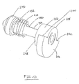
- Each pin 208 has a head 246, a dial 248, and a neck 250 connecting the head 246 to the dial 248.
- the neck 250 is more slender than the head 246 and the dial 248, and the neck 250 has a rounded segment 252 and a keyed (or flattened) segment 254.
- the head 246 is generally conical, and the dial 248 has a base 256 and a substantially semi-annular disc 258 extending from the base 256.
- the disc 258 defines a first face 260 and a second face 262 that are angularly spaced from one another by about 180°. In other embodiments, however, the faces 260, 262 of the disc 258 may be spaced apart from one another at any suitable angle.
- the top half 146 of the hinge 106 has the spacers 204 fastened to their respective drive arms 234 using fasteners 264 inserted into the associated fastener holes 238, 242 such that the pin holes 240, 244 are substantially aligned with one another.
- the brackets 206 are mounted on the main panel 214 such that each guide arm 230 is situated in a respective one of the channels 220, with each connector arm 232 at least partially spanning a respective one of the windows 218 such that the drive arms 234 extend through the windows 218 to align the pin hole 244 of each spacer 204 with the passage 222 of each respective top leaf 216 of the chassis 202.
- each pin 208 extends through the passage 222 of its associated top leaf 216 such that the head 246 of each pin 208 is disposed between its corresponding spacer 204 and top leaf 216, with the pin biasing element 210 circumscribing the neck 250 between the top leaf 216 and the spacer 204 such that the dial 248 is outward of the top leaf 216 and the head 246 is inward of the top leaf 216.
- the keyed segment 254 of the neck 250 is inserted into the oblong passage 222 of the top leaf 216 to facilitate preventing the pin 208 from rotating relative to the top leaf 216.
- the conical head 246 of the pin 208 extends at least partially into the pin hole 244 of the spacer 204.
- the chassis 202 is fastened to the top housing 136 using a plurality of fasteners 266 inserted through the fastener apertures 226 of the main panel 214 such that a pair of the fasteners 266 extends through the pair 228 of fastener apertures 226 associated with the channels 220 of the main panel 214 so as to pass through the guide holes 236 of the guide arm 230 of the bracket 206.
- the guide arm 230 of the bracket 206 is slidable along its respective channel 220 of the main panel 214 such that the pair of fasteners 266 guides the direction of bracket's sliding movement and limits the inward/outward displacement of the bracket 206.
- the main panel 214 and the top housing 136 together define a slit 270 (shown in Figs. 6 , 16 , and 18 ) providing access to each guide arm 230 for displacing the guide arm 230 outward using, for example, the wedges 154 of the top grill plate 144 as set forth in more detail below.
- each of the brackets 206 may also be connected to the main panel 214 via a bracket biasing element 268 (shown in Figs. 11 and 12 ) that assists to bias the guide arms 230 of the brackets 206 inward within the channels 220.
- each pin 208 is biased toward its corresponding top leaf 216.
- the guide arms 230 of the brackets 206 are displaced outward within the channels 220, the guide arms 230 displace the drive arms 234 toward the top leaves 216 such that the drive arms 234 drive the heads 246 of their corresponding pins 208 toward their corresponding top leaves 216 via the spacers 204.
- the dials 248 of the pins 208 are thereby driven outward away from the top leaves 216.
- the pins 208 are biased inward by the pin biasing elements 210, and the pins 208 can be driven outward (against such bias) by displacing the guide arms 230 outward.
- Figs. 14-16 illustrate the top grill unit 104 pivotably attached to the bottom grill unit 102 via the hinge 106.
- the top half 146 of the hinge 106 is connected to the bottom half 118 of the hinge 106 such that each pin 208 is inserted through one of the slots 122 of one of the bottom leaves 120.
- Each pin 208 further extends through the passage 222 of its corresponding top leaf 216, and its associated pin biasing element 210.
- each bottom leaf 120 is sandwiched between one of the discs 258 and one of the top leaves 216 to retain the bottom leaves 120 on the pins 208.
- any pivoting movement (i.e., opening or closing) of the top grill unit 104 relative to the bottom grill unit 102 causes the pins 208 to rotate within their respective slots 122.
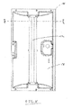
- the top grill unit 104 is pivoted open from its fully closed position (illustrated in Fig. 1 )
- the top leaves 216 contact, and pivot about, the fulcrum structures 124 to drive the pins 208 to the upper ends 128 of their respective slots 122.
- the top grill unit 104 cannot be pivoted any further, and the top grill unit 104 is considered to be fully opened (as illustrated in Figs. 14-16 ).
- the wedges 154 (illustrated in Fig. 5 ) are inserted into the slits 270, pushing the guide arms 230 outward in their respective channels 220 against the force of the pin biasing elements 210 (and optionally the force of the bracket biasing elements 268).
- the pins 208 are thereby pushed outward such that, as the top grill unit 104 is displaced (i.e., raised and lowered, or pivoted open and closed), the discs 258 do not enter the recesses 130 when the pins 208 are at the upper ends 128 of the slots 122.
- the top grill unit 104 enjoys its full range of vertical motion (i.e., any desired vertical displacement of the pins 208 between the lower ends 126 and the upper ends 128 of the slots 122) and its full range of pivoting motion (i.e., any desired angular displacement of the top grill plate 144 from the bottom grill plate 110 such as, for example, within a 105° range of pivot).
- the wedges 154 are withdrawn from the slits 270.
- the guide arms 230 are no longer held outward by the wedges 154, and the pin biasing elements 210 are permitted to somewhat decompress.
- the pin biasing elements 210 bias the pins 208 inward by pushing the heads 246 inward, which in turn pushes the spacers 204 and brackets 206 inward.
- the discs 258 retract inward into the recesses 130 of the bottom leaves 120.
- the discs 258 inhibit the pins 208 from lowering within the slots 122 and limit the pivoting range of the top grill unit 104.
- the bracket biasing elements 268 may optionally be utilized to pull the brackets 206 inward after the top grill plate 144 has been removed, thereby assisting the pin biasing elements 210 in pushing the pins 208 inward.
- the hinge 106 permits the top housing 136 to be closed only to a point at which the reflector 138, the guard 140, and the heating element 142 are suspended above the bottom grill plate 110 and, therefore, above a food product disposed on the bottom grill plate 110.
- the grill 100 is able to perform a broiling function using the top grill unit 104.
- the infrared energy emitted by the heating element 142 of the top grill unit 104 is minimally obstructed in its path to the food product disposed on the bottom grill plate 110.
- the corresponding incidence of infrared energy over the food product thereby broils the food product.
- the grill 100 may be provided with a retractable prop 272 (e.g., a foldable or a telescoping prop) stowed within the top grill unit 104 or the bottom grill unit 102.
- the prop 272 is extendable between the top grill unit 104 and the bottom grill unit 102 during broiling to facilitate supporting the top grill unit 104 in substantially parallel, spaced relation with the bottom grill unit 102 (i.e., to facilitate assisting the hinge 106 in supporting the weight of the top grill unit 104 during broiling).
- the heating element 142 of the bottom grill unit 102 may or may not be energized during broiling, such that the food product may or may not be heated from underneath by the bottom grill unit 102 during broiling.
- the top grill unit 104 can again be pivoted open such that the discs 258 rotate in the opposite direction within the recesses 130 until the other faces 260, 262 of the discs 258 contact the associated stopper 132.
- the top leaves 216 would again be at rest on the fulcrum structures 124, at which point the top plate 144 can again be mounted on the top housing 136.
- the wedges 154 can be reinserted into the slits 270 to again displace the guide arms 230 outward, compressing the pin biasing elements 210 and pushing the discs 258 out of the recesses 130.
- the top grill unit 104 would again enjoy its full range of vertical motion (i.e., any desired vertical displacement of the pins 208 between the lower ends 126 and the upper ends 128 of the slots 122) and its full range of pivoting motion (i.e., any desired angular displacement of the top grill plate 144 from the bottom grill plate 110).
- the hinge 106 are contemplated, enabling any desired relative positioning of the grill units 102, 104 (and, therefore, any desired orientation of the associated grill plates 110, 144 relative to one another).
- each heating element 142 may be provided with a reflective coating (e.g., a gold coating) on its region of the tube 174 that faces away from the food product (as set forth above) to reflect infrared energy emitted from the filament 182 toward the food product.
- the heating element(s) 142 could be mounted behind a transparent or translucent glass plate (much like the headlight of an automobile).
- the underside of at least one grill plate 110, 144 may be coated in a heat absorbing material (e.g., a black paint) to facilitate absorbing the infrared energy and more evenly spreading the associated heat along the grill plate 110, 144 to provide for more uniform heating of the food product contacting the grill plate 110, 144.
- a heat absorbing material e.g., a black paint
- the underside of at least one grill plate 110, 144 may be unevenly contoured such that the angle of light absorption would be optimized for a more uniform spreading of heat over the grill plate 110, 144 given that, if the underside is made flat, it may get hotter in the middle and cooler at the periphery.
- At least one grill plate 110, 144 may be fabricated from a transparent or translucent material (e.g., a glass material), enabling the infrared energy emitted by the heating element 142 to pass through the grill plate 110, 144, rather than being absorbed by the grill plate 110, 144 (e.g., the broiling operation described above could then be performed with the top grill plate 144 attached to the top housing 136).
- a transparent or translucent material e.g., a glass material
- the top grill plate 144 (and/or the bottom grill plate 110) may be provided with cool-touch handles 152 that are sized such that, when the top grill plate 144 has been removed from the top housing 136 for broiling, the top grill plate 144 (which may be hot) can be placed on a support surface (such as a countertop) in a manner that only the handles 152 contact the support surface, thereby inhibiting the top grill plate 144 from heating the support surface when not in use.
- a support surface such as a countertop
- the grill 100 may be configured with an electrical switch that stops the flow of electrical current to the heating element 142 of the top grill unit 104 if the top grill plate 144 has been removed and the top grill unit 104 is pivoted open.
- the grill 100 may be suitably configured to selectively modulate electrical current to the various heating elements 142 depending upon a user-selected mode of operation (e.g., the grill 100 may be configured to provide full power to the heating element 142 of the top grill unit 104 when the top grill plate 144 has been removed and the top grill unit 104 is in its broiling position, as opposed to providing less than full power to the heating element 142 of the top grill unit 104 in other instances).
- the bottom grill plate 110 of the bottom grill unit 102 may be replaced with a flat grill plate (or "pizza stone" 300 as illustrated in Fig. 23 ) that is more suitable for heating a pizza when the grill 100 is in the broiling mode described above.
- the illustrated pizza stone 300 is fabricated from a ceramic material (i.e., an inorganic, nonmetallic solid having a crystalline or semi-crystalline structure formed through heating and cooling processes).
- the pizza stone 300 has a flat top surface 302 (on which a pizza is to be placed) and a uniform thickness TT spanning the perimeter of the top surface 302.
- the ceramic material of the pizza stone 300 provides thermal emittance benefits and thermal capacitance benefits (e.g., heat distribution benefits due, at least in part, to its increased thermal mass and infrared energy (IR) emitting properties, etc.), as well as providing moisture absorption benefits.
- thermal emittance benefits and thermal capacitance benefits e.g., heat distribution benefits due, at least in part, to its increased thermal mass and infrared energy (IR) emitting properties, etc.
- IR infrared energy
- the embodiments of the grill 100 described herein in combination with the pizza stone 300 and, optionally, the quartz-type heating element(s) 142 provides superior functionality when heating a food product such as a pizza.
- another pizza stone embodiment 400 may have integrally formed, vertically extending sidewalls 406 configured to at least partially surround the pizza and substantially enclose an intermediate space SS (illustrated in Fig. 19 ) between the grill units 102, 104, thereby effectuating the functionality of a brick-oven-style heating operation.
- the top surfaces 302, 402 of the pizza stones 300, 400 are entirely flat (i.e., do not have ribs or other protrusions typically associated with grill plates for use in heating meat), the top surfaces 302, 402 do not have protrusions that would inhibit the entire underside of a pizza from remaining in contact with the top surfaces 302, 402 of the pizza stones 300, 400 during heating. Moreover, the illustrated top surfaces 302, 402 also do not have protrusions near their front edges 304, 404, which enables a pizza to be slid onto the pizza stones 300, 400 without having to pivot the top grill unit 104 open from its broiling position illustrated in Fig. 19 .
Abstract
Description
- The present invention relates generally to heating appliances and, more particularly, to a tabletop grill for use in heating a food product.
- Many conventional tabletop grills have an upper housing and a lower housing that are connected together via a hinge in a clamshell-type configuration. A heating element is mounted on each of the housings, and the heating element is configured to heat a grill plate for grilling a food product in contact with the grill plate. However, conventional tabletop grills transfer heat from the heating element to the food product in a less than desirable manner. It would be useful, therefore, to more effectively transfer heat from the heating element to the food product.
- In one embodiment, a tabletop grill generally comprises a first grill unit comprising a first grill plate and a first heating element for heating the first grill plate. The grill further comprises a second grill unit positionable relative to the first grill unit. The second grill unit comprises a second grill plate and a second heating element for heating the second grill plate. The grill is configured to function as a broiler. As used herein, the term "broil" refers to heating by exposure to radiant energy, such as, for example, infrared radiant energy.
- In another embodiment, a tabletop grill generally comprises a first grill unit and a second grill unit positionable relative to the first grill unit. The second grill unit comprises a housing defining an interior space, a quartz-type heating element disposed within the interior space of the housing, and a grill plate mounted on the housing to cover the interior space such that the heating element is configured to heat the grill plate.
- In yet another embodiment, a tabletop grill generally comprises a first grill unit and a second grill unit positionable relative to the first grill unit. The second grill unit comprises a housing defining an interior space, a grill plate removably mounted on the housing to cover the interior space, and a reflector disposed within the interior space. The reflector comprises an upper surface that defines a trough. The second grill unit also comprises a quartz-type heating element mounted within the interior space in spaced relation to the reflector. The heating element extends along the trough such that energy emitted from the heating element impacts the upper surface of the reflector within the through and is reflected toward the grill plate. The grill further comprises a hinge pivotably connecting the first grill unit to the second grill unit. The hinge is configured to limit the range of pivoting motion of the second grill unit relative to the first grill unit when the grill plate is removed from the housing.
-
-
Figure 1 is a perspective view of one embodiment of a tabletop grill; -
Figure 2 is another perspective view of the tabletop grill ofFigure 1 ; -
Figure 3 is a perspective view of a bottom grill unit of the tabletop grill ofFigure 1 ; -
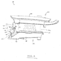
Figure 4 is a perspective view of a top grill unit of the tabletop grill ofFigure 1 ; -
Figure 5 is an exploded view of the top grill unit ofFigure 4 ; -
Figure 6 is a perspective view of the top grill unit ofFigure 4 with its grill plate removed; -
Figure 7 is a cross-sectional view of a heating element of the top grill unit ofFigure 4 ; -
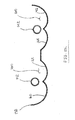
Figure 8 is an elevation view of a reflector of the top grill unit ofFigure 4 ; -
Figure 9 is a cross-sectional view of the reflector ofFigure 8 taken along plane 9-9; -
Figure 10 is a perspective view of a hinge segment of the top grill unit ofFigure 4 ; -
Figure 11 is another perspective view of the hinge segment ofFigure 10 ; -
Figure 12 is an exploded view of the hinge segment ofFigure 10 ; -
Figure 13 is a perspective view of a pin of the hinge segment ofFigure 10 ; -
Figure 14 is a side view of the tabletop grill ofFigure 1 in an open configuration; -
Figure 15 is a perspective view of the tabletop grill ofFigure 1 in the open configuration ofFigure 14 ; -
Figure 16 is an enlarged perspective view of a portion of the tabletop grill ofFigure 1 in the open configuration ofFigure 14 ; -
Figure 17 is a perspective view of the tabletop grill ofFigure 1 in the open configuration ofFigure 14 with the grill plate of the top grill unit removed; -
Figure 18 is an enlarged perspective view of a portion of the tabletop grill ofFigure 1 in the open configuration ofFigure 14 with the grill plate of the top grill unit removed; -
Figure 19 is a side view of the tabletop grill ofFigure 1 in a closed configuration with the grill plate of the top grill unit removed; -
Figure 20 is an enlarged perspective view of the tabletop grill ofFigure 1 in the closed configuration ofFigure 19 ; -
Figure 21 is a side view of the grill plate of the top grill unit ofFigure 4 ; -
Figure 22 is a schematic cross-sectional view of another embodiment of the reflector ofFigure 8 with a pair of the heating elements ofFigure 7 mounted in spaced relation thereto; -
Figure 23 is a perspective view of another embodiment of a grill plate of the tabletop grill ofFigure 1 ; and -
Figure 24 is a perspective view of yet another embodiment of a grill plate of the tabletop grill ofFigure 1 . - Corresponding reference characters indicate corresponding parts throughout the several views of the drawings.
- Referring to the drawings, and in particular to
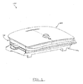
Figs. 1 and2 , a heating appliance (e.g., a tabletop grill according to the illustrated embodiment) is indicated generally by 100. The illustratedgrill 100 comprises a bottom grill unit (indicated generally by 102) and a top grill unit (indicated generally by 104) that are connected together via a hinge (indicated generally by 106). As set forth below, thegrill 100 is configured for heating a food product in a variety of ways, using at least one of thebottom grill unit 102 and thetop grill unit 104. - As illustrated in
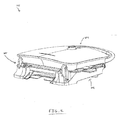
Fig. 3 , thebottom grill unit 102 includes abottom housing 108 and abottom grill plate 110 mounted on thebottom housing 108. Thebottom housing 108 hasfront 112, a back (or rear) 114, and at least onefoot 116 for supporting thegrill 100 on a support surface (e.g., a flat tabletop or countertop surface). Theback 114 of thebottom housing 108 defines abottom half 118 of thehinge 106, which includes a pair ofbottom leaves 120 that each defines a substantiallyvertical slot 122. Theback 114 of thebottom housing 108 also includes a pair offulcrum structures 124 each situated rearward of one of theslots 122. In this manner, eachfulcrum structure 124 is vertically spaced about midway along itsrespective slot 122 in relation to thefoot 116. Moreover, eachslot 122 has a lower end 126, anupper end 128, and a generally C-shaped recess (or counter-depth) 130 circumscribing a portion of theupper end 128 to define astopper 132. Optionally, thebottom grill unit 102 may further include a pivotable stand 134 configured for selectively elevating theback 114 of thebottom housing 108 to increase the angle of thebottom grill plate 110 relative to the support surface if desired. By elevating theback 114 of thebottom housing 108, grease can be more effectively drained from thebottom grill plate 110 while heating a food product. - As used herein, the term "vertical" refers to a dimension that is to be oriented perpendicular to the support surface upon which the
foot 116 of thegrill 100 is to be seated during operation of thegrill 100. As such, the term "horizontal" refers to a dimension that is oriented perpendicular to vertical. Additionally, as used herein, the term "grill plate" is not limited to an implement having a ribbed food-contacting surface as shown in the illustrated embodiment but, rather, a grill plate may have any suitable food-contacting surface such as a substantially flat (griddle-type) surface, a grated surface, etc. Moreover, the terms "inner," "inward," "outer," "outward," and any variations thereof are directional modifiers indicating a disposition relative to a center E of a pivot axis P of thehinge 106, as shown inFig. 11 (e.g., a grill component may be displaced inward by being moved parallel to the axis P toward the center E, and outward by being moved parallel to the axis P away from the center E). - Referring now to
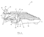
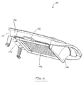
Figs 4-6 , thetop grill unit 104 includes atop housing 136, areflector 138 disposed within thetop housing 136, and aheating element 142 partially surrounded by, and spaced apart from, thereflector 138. Thetop grill unit 104 further includes a guard 140 for theheating element 142, atop grill plate 144 mounted on thetop housing 136 to cover theheating element 142, and atop half 146 of thehinge 106 for pivotably attaching thetop grill unit 104 to thebottom grill unit 102 via thebottom half 118 of thehinge 106. While thereflector 138, the guard 140, and theheating element 142 are described below in terms of thetop grill unit 104, it should be noted that thebottom grill unit 102 has thesame reflector 138, guard 140, andheating element 142 mounted in the same manner within thebottom housing 108 beneath thebottom grill plate 110. - In the illustrated embodiment, the
top housing 136 has a front 148 and a back (or rear) 150. In the same manner as thebottom grill plate 110, thetop grill plate 144 has a pair ofhandles 152 connected thereto, and thehandles 152 are suitably configured such that thetop grill plate 144 can be removed. For example, it may be desirable to remove thetop grill plate 144 from thetop housing 136 to perform a broiling function using thegrill 100, to clean thetop grill plate 144, or to replace thetop grill plate 144 with another grill plate. Moreover, thetop grill plate 144 has a pair of wedges (or cams) 154 extending from itsback side 156 to facilitate operating thehinge 106, as set forth in more detail below. - Notably, the illustrated
grill 100 is configured as a horizontal grill (i.e., a grill configured to heat a food product with the grill plate(s) 110, 144 oriented substantially parallel to the support surface). However, it is contemplated that thegrill 100 may be a vertical grill in other embodiments (i.e., a grill configured to heat a food product with the grill plate(s) 110, 144 oriented substantially perpendicular to the support surface). Alternatively, thegrill 100 may be configured to heat a food product with the grill plate(s) 110, 144 oriented in any suitable manner. - Referring now to
Fig. 7 , the illustratedheating element 142 is a quartz-type heating element configured as follows. Theheating element 142 includes a substantially linearly extending tube 174 having a first end 176, a second end 178, and a body 180 extending from the first end 176 to the second end 178 such that the tube 174 has a lengthC. A filament 182 is disposed within and extends along the length C of the tube 174 substantially from the first end 176 of the tube 174 to the second end 178 of the tube 174. A first electrical lead 184 is connected to thefilament 182 near the first end 176 of the tube 174, and a second electrical lead 186 is connected to thefilament 182 near the second end 178 of the tube 174. - A first end cap 188 is attached to the first end 176 of the tube 174 about the first electrical lead 184 such that the first electrical lead 184 passes through (i.e., is supported within and extends outward from) the first end cap 188. Similarly, a
second end cap 190 is attached to the second end 178 of the tube 174 about the second electrical lead 186 such that the second electrical lead 186 passes through (i.e., is supported within and extends outward from) thesecond end cap 190. In this manner, the first end cap 188 supports the first electrical lead 184, and thesecond end cap 190 supports the second electrical lead 186. Moreover, the end caps 188, 190 are useful in connecting theheating element 142 to thetop housing 136 or a suitable frame disposed within thetop housing 136. Suitably, a first insulator 192 is sandwiched between the first end cap 188 and the tube 174, and asecond insulator 194 is sandwiched between thesecond end cap 190 and the tube 174. Theinsulators 192, 194 facilitate insulating the end caps 188, 190 against conductive heat transfer from the tube 174 to the end caps 188, 190 when theheating element 142 is energized by passing electrical current through thefilament 182 via the electrical leads 184, 186. - In the illustrated embodiment, the end caps 188, 190 are fabricated from a ceramic material, and the
filament 182 is fabricated from a tungsten material or nickel-chromiumiron composite material. Moreover, thefilament 182 is a coiled wire in the illustrated embodiment, with the diameter of each coil and the number of coils being selectable to suit a desired wattage of theheating element 142 and to suit a desired amount of infrared energy emitted from theheating element 142 when theheating element 142 is energized. In that regard, the tube 174 is fabricated from a quartz glass material that may be transparent, translucent (e.g., frosted), or at least partially coated with a reflective material (e.g., a metallic material) to suit a desired amount (and direction) of infrared energy transmitted through the tube 174. Notably, in other embodiments, theheating element 142 may be configured in any suitable manner that facilitates enabling theheating element 142 to function as described herein (e.g., thefilament 182 of theheating element 142 may not be coiled in some embodiments, or in other embodiments the tube 174 may not extend linearly but, rather, may extend along a curvilinear path). - Moreover, the space surrounding the
filament 182 within the tube 174 is open (i.e., the inside of the tube 174 is either under vacuum with gas, or not sealed and exposed to the ambient air). As such, infrared energy emitted from the energizedfilament 182 is permitted to travel from thefilament 182 through the tube 174 with minimal obstruction in some embodiments). Such a configuration of theheating element 142 is distinguishable from a Calrod (RTM) type configuration in which a filament is surrounded by a powdered material and packed within a metal tube such that infrared energy emitted from the filament is obstructed and absorbed by the powdered material in order to heat the metal tube via conduction. - As such, the quartz-
type heating element 142 disclosed herein provides heating properties that are superior to a Calrod (RTM) type heating element. For example, the quartz-type heating element 142 emits more infrared energy in a more focused manner to facilitate quicker heat-up and better control of energy incidence onto thetop grill plate 144 or the food product (e.g., to enable rapid cycling of the amount of infrared energy incidence onto thetop grill plate 144 or the food product such as, for example, at the end of a cooking cycle to perform a final sear operation on the food product). As such, the quartz-type heating element 142 disclosed herein permits thegrill 100 to be used in a plurality of alternate configurations to heating a food product in a ways that would not be effective (or practical) via a Calrod (RTM) type heating element (e.g., broiling a food product using thetop grill unit 104 as set forth below would not be effective or practical using a Calrod (RTM) type heating element). Notably, in alternative embodiments of thegrill 100, the heating element(s) 142 may be any suitable type of heating element other than a quartz-type heating element, such as, for example, a ceramic-type heating element, a halogen-type heating element, a Calrod (RTM) type heating element, etc. - Moreover, the
heating element 142 may emit infrared energy unevenly along its length C (e.g., theheating element 142 may emit more infrared energy near its center than near its end caps 188, 190). In that regard, the guard 140 of thetop grill unit 104 may be suitably configured as a heat distribution member (or grating) for use when thetop grill plate 144 of thetop grill unit 104 is removed during a broiling operation of thetop grill unit 104, as set forth in more detail below. Notably, the guard 140 may be fabricated from any suitable material (e.g., a metallic material, or a glass (or other transparent or translucent) material. Alternatively, thetop grill unit 104 may not include the guard 140. As used herein, the term "heat distribution member" is intended to broadly refer to any structure that facilitates changing (e.g., diffracting, deflecting, and/or reflecting) the direction of at least some energy emitted from theheating element 142 over the food product. - When configured as a heat distribution member, the guard 140 would have its apertures optimized to more evenly distribute infrared energy incidence from the
heating element 142 of thetop grill unit 104 over the food product during broiling. Suitably, the guard 140 may be mounted in any manner and may be fabricated in any shape (using any material) that facilitates enabling the guard 140 to prevent a food product from contacting theheating element 142, and/or to function as a heat distribution member. Notably, another potential solution for mitigating the uneven emittance of theheating element 142 is to provide a higher density of coils near the end caps 188, 190 than near the center of theheating element 142. This could be done in conjunction with, or in lieu of, the guard 140 being configured as a heat distribution member. - With reference now to
Figs. 8 and9 , the illustratedreflector 138 has a generally rectangular planform shape, and a concaveupper surface 158 that defines atrough 160 sized to receive theheating element 142 such that thetrough 160 extends along a path that mirrors the path along which theheating element 142 extends. - In the illustrated embodiment of the
reflector 138, thetrough 160 has a contour (or profile) that is substantially W-shaped. In this manner, thetrough 160 defines a pair of side-by-side depressions 162, with theheating element 142 spaced apart from thereflector 138 at the intersection of thedepressions 162. Eachdepression 162 extends along the entire length of thereflector 138, and thedepressions 162 intersect one another at an axis B such that thetrough 160 is substantially symmetric about the axis B. In another embodiment, illustrated inFIG. 22 , thereflector 138 is contoured to define a pair of substantially W-shapedtroughs 160 that are side-by-side. Eachtrough 160 is sized to receive arespective heating element 142, and eachtrough 160 extends along a path that mirrors the path along which its associatedheating element 142 extends. Such adualtrough reflector 138 may be useful, for example, on larger grills that utilize a pair ofheating elements 142 in thetop grill unit 104. - Alternatively, the
upper surface 158 may define any suitable number oftroughs 160 having any suitable number ofdepressions 162 arranged in any suitable manner. Moreover, thereflector 138 may be formed from a plurality of smaller reflectors that are connected together as an assembly (or are disconnected and arranged adjacent to one another) to perform the functions described herein, rather than being a single, integrally formed reflector as illustrated. Moreover, thereflector 138 may be suitably fabricated from an aluminum material (e.g., a suitable metal substrate coated in aluminum). Alternatively, thereflector 138 may be fabricated from any suitable material that enables thereflector 138 to function as described herein (e.g., a metal substrate coated in a zinc material such as galvanized steel). - During operation of the
grill 100, theheating element 142 is energized (by passing current through thefilament 182 via the electrical leads 184, 186), and infrared energy is emitted from thefilament 182, and the infrared energy passes through the tube 174 with minimal obstruction. When thetop grill plate 144 is mounted on thetop housing 136, the infrared energy emitted from the upper region of theheating element 142 has a direct path to impacting an underside of thetop grill plate 144. Moreover, the infrared energy emitted from the lower region of theheating element 142 has an indirect path to thetop grill plate 144 by reflecting off of theupper surface 158 of thereflector 138 within thetrough 160. More specifically, thedepressions 162 reflect the infrared energy from theheating element 142 toward the underside of thetop grill plate 144 in a direction that is substantially parallel to the axis B. - Referring now to
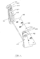
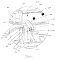
Figs. 10-13 , thetop half 146 of thehinge 106 includes a chassis 202, a pair ofspacers 204, and a pair of brackets 206. Thetop half 146 of thehinge 106 further includes a pair ofpins 208, and a pair ofpin biasing elements 210. In alternative embodiments, thetop half 146 of thehinge 106 may have any suitable components that facilitate enabling thehinge 106 to function as described herein. - The illustrated chassis 202 has a
main panel 214 and a pair of top leaves 216. Themain panel 214 has a pair of windows 218, and each window 218 is disposed adjacent to, and inward of, a respective one of the top leaves 216. Themain panel 214 also has a pair of channels 220, with each channel 220 being oriented substantially perpendicular to a respective one of the windows 218 such that the each channel 220 overlaps its corresponding window 218 to together form a substantially L-shaped inset in themain panel 214. Eachtop leaf 216 has anoblong passage 222 near itsdistal end 224, and themain panel 214 has a plurality of fastener apertures 226 for fastening the chassis 202 to thetop housing 136. Notably, apair 228 of the fastener apertures 226 extends through each of the channels 220 of themain panel 214. - Each bracket 206 has a
guide arm 230 and aconnector arm 232 that are generally coplanar and are oriented substantially perpendicular to one another in a generally L-shaped manner. The bracket 206 also has as adrive arm 234 that extends from theconnector arm 232 in a plane that is substantially perpendicular to the plane shared by theguide arm 230 and theconnector arm 232. Theguide arm 230 has a pair of elongate guide holes 236, and thedrive arm 234 has a fastener hole 238 and apin hole 240 arranged in spaced relation to one another. Moreover, eachspacer 204 has afastener hole 242 and apin hole 244 that are spaced apart in the same manner as the fastener hole 238 and thepin hole 240 of thedrive arm 234 so as to be aligned with the fastener hole 238 and thepin hole 240 of thedrive arm 234 when eachspacer 204 is fastened to its associated bracket 206, as set forth in more detail below. - Each
pin 208 has ahead 246, adial 248, and aneck 250 connecting thehead 246 to thedial 248. Notably, theneck 250 is more slender than thehead 246 and thedial 248, and theneck 250 has a roundedsegment 252 and a keyed (or flattened)segment 254. Thehead 246 is generally conical, and thedial 248 has abase 256 and a substantiallysemi-annular disc 258 extending from thebase 256. Thedisc 258 defines afirst face 260 and asecond face 262 that are angularly spaced from one another by about 180°. In other embodiments, however, thefaces disc 258 may be spaced apart from one another at any suitable angle. - In its assembled configuration, the
top half 146 of thehinge 106 has thespacers 204 fastened to theirrespective drive arms 234 usingfasteners 264 inserted into the associated fastener holes 238, 242 such that the pin holes 240, 244 are substantially aligned with one another. Moreover, the brackets 206 are mounted on themain panel 214 such that eachguide arm 230 is situated in a respective one of the channels 220, with eachconnector arm 232 at least partially spanning a respective one of the windows 218 such that thedrive arms 234 extend through the windows 218 to align thepin hole 244 of eachspacer 204 with thepassage 222 of each respectivetop leaf 216 of the chassis 202. - Additionally, each
pin 208 extends through thepassage 222 of its associatedtop leaf 216 such that thehead 246 of eachpin 208 is disposed between itscorresponding spacer 204 andtop leaf 216, with thepin biasing element 210 circumscribing theneck 250 between thetop leaf 216 and thespacer 204 such that thedial 248 is outward of thetop leaf 216 and thehead 246 is inward of thetop leaf 216. In this manner, thekeyed segment 254 of theneck 250 is inserted into theoblong passage 222 of thetop leaf 216 to facilitate preventing thepin 208 from rotating relative to thetop leaf 216. Moreover, theconical head 246 of thepin 208 extends at least partially into thepin hole 244 of thespacer 204. - The chassis 202 is fastened to the
top housing 136 using a plurality of fasteners 266 inserted through the fastener apertures 226 of themain panel 214 such that a pair of the fasteners 266 extends through thepair 228 of fastener apertures 226 associated with the channels 220 of themain panel 214 so as to pass through the guide holes 236 of theguide arm 230 of the bracket 206. In this manner, theguide arm 230 of the bracket 206 is slidable along its respective channel 220 of themain panel 214 such that the pair of fasteners 266 guides the direction of bracket's sliding movement and limits the inward/outward displacement of the bracket 206. Moreover, due to the channels 220 being inset, themain panel 214 and thetop housing 136 together define a slit 270 (shown inFigs. 6 ,16 , and18 ) providing access to eachguide arm 230 for displacing theguide arm 230 outward using, for example, thewedges 154 of thetop grill plate 144 as set forth in more detail below. - Because the
pin biasing element 210 is disposed between thetop leaf 216 of the chassis 202 and thehead 246 of thepin 208, thehead 246 of thepin 208 is biased away from thetop leaf 216. As such, thespacer 204 is also biased away from thetop leaf 216, and theguide arm 230 of the bracket 206 is thereby biased inward within its respective channel 220. Optionally, each of the brackets 206 may also be connected to themain panel 214 via a bracket biasing element 268 (shown inFigs. 11 and12 ) that assists to bias theguide arms 230 of the brackets 206 inward within the channels 220. - In this manner, the
dial 248 of eachpin 208 is biased toward its correspondingtop leaf 216. Thus, as set forth in more detail below, when theguide arms 230 of the brackets 206 are displaced outward within the channels 220, theguide arms 230 displace thedrive arms 234 toward the top leaves 216 such that thedrive arms 234 drive theheads 246 of theircorresponding pins 208 toward their corresponding top leaves 216 via thespacers 204. Thedials 248 of thepins 208 are thereby driven outward away from the top leaves 216. As such, thepins 208 are biased inward by thepin biasing elements 210, and thepins 208 can be driven outward (against such bias) by displacing theguide arms 230 outward. -
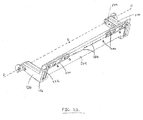
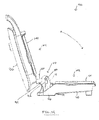
Figs. 14-16 illustrate thetop grill unit 104 pivotably attached to thebottom grill unit 102 via thehinge 106. Specifically, thetop half 146 of thehinge 106 is connected to thebottom half 118 of thehinge 106 such that eachpin 208 is inserted through one of theslots 122 of one of the bottom leaves 120. Eachpin 208 further extends through thepassage 222 of its correspondingtop leaf 216, and its associatedpin biasing element 210. In this manner, eachbottom leaf 120 is sandwiched between one of thediscs 258 and one of the top leaves 216 to retain the bottom leaves 120 on thepins 208. - Because the keyed
segments 254 of thepins 208 are inserted into theoblong passages 222 of the associated top leaves 216, any pivoting movement (i.e., opening or closing) of thetop grill unit 104 relative to thebottom grill unit 102 causes thepins 208 to rotate within theirrespective slots 122. In this manner, as thetop grill unit 104 is pivoted open from its fully closed position (illustrated inFig. 1 ), the top leaves 216 contact, and pivot about, thefulcrum structures 124 to drive thepins 208 to the upper ends 128 of theirrespective slots 122. Upon thepins 208 reaching the upper ends 128 of theslots 122, thetop grill unit 104 cannot be pivoted any further, and thetop grill unit 104 is considered to be fully opened (as illustrated inFigs. 14-16 ). - Notably, because the
top grill plate 144 is attached to thetop housing 136, the wedges 154 (illustrated inFig. 5 ) are inserted into theslits 270, pushing theguide arms 230 outward in their respective channels 220 against the force of the pin biasing elements 210 (and optionally the force of the bracket biasing elements 268). Thepins 208 are thereby pushed outward such that, as thetop grill unit 104 is displaced (i.e., raised and lowered, or pivoted open and closed), thediscs 258 do not enter therecesses 130 when thepins 208 are at the upper ends 128 of theslots 122. Thus, when thetop grill plate 144 is attached, thetop grill unit 104 enjoys its full range of vertical motion (i.e., any desired vertical displacement of thepins 208 between the lower ends 126 and the upper ends 128 of the slots 122) and its full range of pivoting motion (i.e., any desired angular displacement of thetop grill plate 144 from thebottom grill plate 110 such as, for example, within a 105° range of pivot). - With reference now to
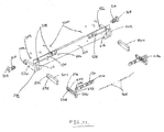
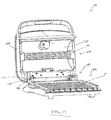
Figs. 17 and18 , if thetop grill plate 144 is removed from thetop housing 136, thewedges 154 are withdrawn from theslits 270. Thus, theguide arms 230 are no longer held outward by thewedges 154, and thepin biasing elements 210 are permitted to somewhat decompress. Specifically, thepin biasing elements 210 bias thepins 208 inward by pushing theheads 246 inward, which in turn pushes thespacers 204 and brackets 206 inward. As such, when thetop grill plate 144 has been removed and thepins 208 are disposed at the upper ends 128 of theslots 122, thediscs 258 retract inward into therecesses 130 of the bottom leaves 120. In such a position, thediscs 258 inhibit thepins 208 from lowering within theslots 122 and limit the pivoting range of thetop grill unit 104. Again, the bracket biasing elements 268 (illustrated inFigs. 11 and12 ) may optionally be utilized to pull the brackets 206 inward after thetop grill plate 144 has been removed, thereby assisting thepin biasing elements 210 in pushing thepins 208 inward. - As illustrated in
Figs. 19 and20 , if thetop grill unit 104 is pivoted closed after thetop grill plate 144 has been removed and thepins 208 have been retracted inward such that thediscs 258 are in therecesses 130, thediscs 258 rotate within therecesses 130 until one of thefaces disc 258 contacts its associatedstopper 132 to halt the pivoting movement of thetop grill unit 104. Specifically, thehinge 106 permits thetop housing 136 to be closed only to a point at which thereflector 138, the guard 140, and theheating element 142 are suspended above thebottom grill plate 110 and, therefore, above a food product disposed on thebottom grill plate 110. - In such a position, the
grill 100 is able to perform a broiling function using thetop grill unit 104. Specifically, with thetop grill plate 144 removed, the infrared energy emitted by theheating element 142 of thetop grill unit 104 is minimally obstructed in its path to the food product disposed on thebottom grill plate 110. The corresponding incidence of infrared energy over the food product thereby broils the food product. - Moreover, in some embodiments, the
grill 100 may be provided with a retractable prop 272 (e.g., a foldable or a telescoping prop) stowed within thetop grill unit 104 or thebottom grill unit 102. The prop 272 is extendable between thetop grill unit 104 and thebottom grill unit 102 during broiling to facilitate supporting thetop grill unit 104 in substantially parallel, spaced relation with the bottom grill unit 102 (i.e., to facilitate assisting thehinge 106 in supporting the weight of thetop grill unit 104 during broiling). Optionally, theheating element 142 of thebottom grill unit 102 may or may not be energized during broiling, such that the food product may or may not be heated from underneath by thebottom grill unit 102 during broiling. - After broiling the food product, the
top grill unit 104 can again be pivoted open such that thediscs 258 rotate in the opposite direction within therecesses 130 until the other faces 260, 262 of thediscs 258 contact the associatedstopper 132. In such a position, the top leaves 216 would again be at rest on thefulcrum structures 124, at which point thetop plate 144 can again be mounted on thetop housing 136. Specifically, thewedges 154 can be reinserted into theslits 270 to again displace theguide arms 230 outward, compressing thepin biasing elements 210 and pushing thediscs 258 out of therecesses 130. As such, thetop grill unit 104 would again enjoy its full range of vertical motion (i.e., any desired vertical displacement of thepins 208 between the lower ends 126 and the upper ends 128 of the slots 122) and its full range of pivoting motion (i.e., any desired angular displacement of thetop grill plate 144 from the bottom grill plate 110). Notably, many other embodiments of thehinge 106 are contemplated, enabling any desired relative positioning of thegrill units 102, 104 (and, therefore, any desired orientation of the associatedgrill plates - Moreover, in one embodiment, only the top grill unit 104 (not the bottom grill unit 102) is provided with the quartz-
type heating element 142 described herein, or vice versa. In another embodiment, rather than using thereflector 138 described above, eachheating element 142 may be provided with a reflective coating (e.g., a gold coating) on its region of the tube 174 that faces away from the food product (as set forth above) to reflect infrared energy emitted from thefilament 182 toward the food product. In other embodiments, the heating element(s) 142 could be mounted behind a transparent or translucent glass plate (much like the headlight of an automobile). - In some embodiments, the underside of at least one
grill plate grill plate grill plate grill plate grill plate grill plate heating element 142 to pass through thegrill plate grill plate 110, 144 (e.g., the broiling operation described above could then be performed with thetop grill plate 144 attached to the top housing 136). - Optionally, as illustrated in
Fig. 21 , the top grill plate 144 (and/or the bottom grill plate 110) may be provided with cool-touch handles 152 that are sized such that, when thetop grill plate 144 has been removed from thetop housing 136 for broiling, the top grill plate 144 (which may be hot) can be placed on a support surface (such as a countertop) in a manner that only thehandles 152 contact the support surface, thereby inhibiting thetop grill plate 144 from heating the support surface when not in use. - In some embodiments, the
grill 100 may be configured with an electrical switch that stops the flow of electrical current to theheating element 142 of thetop grill unit 104 if thetop grill plate 144 has been removed and thetop grill unit 104 is pivoted open. Moreover, thegrill 100 may be suitably configured to selectively modulate electrical current to thevarious heating elements 142 depending upon a user-selected mode of operation (e.g., thegrill 100 may be configured to provide full power to theheating element 142 of thetop grill unit 104 when thetop grill plate 144 has been removed and thetop grill unit 104 is in its broiling position, as opposed to providing less than full power to theheating element 142 of thetop grill unit 104 in other instances). - In other embodiments, when the
top grill plate 144 is removed from thetop housing 136, thebottom grill plate 110 of thebottom grill unit 102 may be replaced with a flat grill plate (or "pizza stone" 300 as illustrated inFig. 23 ) that is more suitable for heating a pizza when thegrill 100 is in the broiling mode described above. The illustratedpizza stone 300 is fabricated from a ceramic material (i.e., an inorganic, nonmetallic solid having a crystalline or semi-crystalline structure formed through heating and cooling processes). Moreover, thepizza stone 300 has a flat top surface 302 (on which a pizza is to be placed) and a uniform thickness TT spanning the perimeter of thetop surface 302. - When compared to metallic grill plates, the ceramic material of the
pizza stone 300 provides thermal emittance benefits and thermal capacitance benefits (e.g., heat distribution benefits due, at least in part, to its increased thermal mass and infrared energy (IR) emitting properties, etc.), as well as providing moisture absorption benefits. Thus, the embodiments of thegrill 100 described herein in combination with thepizza stone 300 and, optionally, the quartz-type heating element(s) 142, provides superior functionality when heating a food product such as a pizza. Optionally, as shown inFig. 24 , anotherpizza stone embodiment 400 may have integrally formed, vertically extending sidewalls 406 configured to at least partially surround the pizza and substantially enclose an intermediate space SS (illustrated inFig. 19 ) between thegrill units - Because the illustrated
top surfaces pizza stones top surfaces top surfaces pizza stones top surfaces front edges pizza stones top grill unit 104 open from its broiling position illustrated inFig. 19 . - When introducing elements of the present invention or the preferred embodiment(s) thereof, the articles "a", "an", "the", and "said" are intended to mean that there are one or more of the elements. The terms "comprising", "including", and "having" are intended to be inclusive and mean that there may be additional elements other than the listed elements.
- As various changes could be made in the above constructions without departing from the scope of the invention, it is intended that all matter contained in the above description or shown in the accompanying drawings shall be interpreted as illustrative and not in a limiting sense.
Claims (15)
- A tabletop grill comprising:a first grill unit; anda second grill unit positionable relative to the first grill unit, the second grill unit comprising:a housing defining an interior space;a quartz-type heating element disposed within the interior space of the housing; anda grill plate mounted on the housing to cover the interior space such that the heating element is configured to heat the grill plate.
- The tabletop grill of claim 1, wherein the heating element comprises a tube and a filament disposed within the tube such that open space surrounds the filament within the tube, the tube being one of transparent and translucent.
- The tabletop grill of claim 1 or 2, wherein the grill plate is removably mounted on the housing.
- The tabletop grill of any of claims 1 to 3, wherein the grill comprises a heat distribution member disposed within the interior space of the housing to facilitate evenly distributing energy emitted from the heating element.
- The tabletop grill of claim 4, wherein the heat distribution member is a grating.
- The tabletop grill of any preceding claim, wherein the second grill unit is configured for vertical displacement relative to the first grill unit to vary spacing between the grill units.
- The tabletop grill of any preceding claim, wherein the second grill unit comprises a reflector configured to direct energy emitted from the heating element toward the grill plate.
- The tabletop grill of claim 7, wherein the reflector has an upper surface that is contoured to define a trough sized to receive the heating element.
- The tabletop grill of claim 8, wherein the trough has a pair of side-by-side depressions that extend along the length of the heating element.
- The tabletop grill of claim 9, wherein the heating element is disposed between the depressions.
- The tabletop grill of any preceding claim, wherein the grill comprises a hinge pivotably connecting the first grill unit to the second grill unit, and wherein the grill plate is removable from the housing, the hinge being configured to limit the range of pivoting motion of the second grill unit relative to the first grill unit when the grill plate is removed from the housing.
- The tabletop grill of claim 11, wherein the hinge comprises a spring loaded pin configured for displacement when the grill plate is removed from the housing to facilitate limiting the range of pivoting motion of the second grill unit.
- The tabletop grill of any preceding claim, wherein the grill plate is one of transparent and translucent.
- A tabletop grill comprising:a first grill unit comprising a first grill plate and a first heating element for heating the first grill plate; anda second grill unit positionable relative to the first grill unit, the second grill unit comprising a second grill plate and a second heating element for heating the second grill plate, wherein the grill is configured to function as a broiler.
- The tabletop grill of claim 14, wherein the grill comprises a hinge pivotably connecting the first grill unit to the second grill unit, and wherein the second grill unit comprises a housing on which the second grill plate is mounted such that the second grill plate is removable from the housing, the hinge being configured to limit the range of pivoting motion of the second grill unit relative to the first grill unit when the second grill plate is removed from the housing.
Applications Claiming Priority (3)
| Application Number | Priority Date | Filing Date | Title |
|---|---|---|---|
| US201361829844P | 2013-05-31 | 2013-05-31 | |
| US201361834331P | 2013-06-12 | 2013-06-12 | |
| US201361896404P | 2013-10-28 | 2013-10-28 |
Publications (1)
| Publication Number | Publication Date |
|---|---|
| EP2807967A1 true EP2807967A1 (en) | 2014-12-03 |
Family
ID=50842139
Family Applications (1)
| Application Number | Title | Priority Date | Filing Date |
|---|---|---|---|
| EP20140170674 Withdrawn EP2807967A1 (en) | 2013-05-31 | 2014-05-30 | Tabletop grill |
Country Status (4)
| Country | Link |
|---|---|
| US (2) | US9901209B2 (en) |
| EP (1) | EP2807967A1 (en) |
| CN (1) | CN104207658B (en) |
| CA (1) | CA2852976A1 (en) |
Cited By (1)
| Publication number | Priority date | Publication date | Assignee | Title |
|---|---|---|---|---|
| WO2017151374A1 (en) * | 2016-03-01 | 2017-09-08 | Spectrum Brands, Inc. | Bonfire grilling appliance |
Families Citing this family (5)
| Publication number | Priority date | Publication date | Assignee | Title |
|---|---|---|---|---|
| CN105310523B (en) | 2014-06-23 | 2017-09-22 | 漳州灿坤实业有限公司 | The cooked device of food |
| CN204169682U (en) * | 2014-11-11 | 2015-02-25 | 漳州灿坤实业有限公司 | The pivoting device of culinary art facility |
| USD844366S1 (en) | 2017-03-31 | 2019-04-02 | Spectrum Brands, Inc. | Grill |
| KR101838855B1 (en) * | 2017-08-16 | 2018-03-14 | 자이글주식회사 | Apparatus roaster with foldable heater and roast plate |
| JP1673075S (en) * | 2019-12-30 | 2020-11-24 |
Citations (4)
| Publication number | Priority date | Publication date | Assignee | Title |
|---|---|---|---|---|
| FR1551844A (en) * | 1967-01-26 | 1968-12-27 | ||
| US20050132900A1 (en) * | 2003-12-18 | 2005-06-23 | Hp Intellectual Corporation | Toaster using infrared heating for reduced toasting time |
| US20110062151A1 (en) * | 2007-11-20 | 2011-03-17 | Electrolux Professional S.P.A. | Apparatus for cooking food products on both sides thereof |
| FR2975883A1 (en) * | 2011-06-06 | 2012-12-07 | Raymond Damon | Cooking device for cooking e.g. food, has heating assembly including infrared radiant emitters, and base including reciprocating grate placed on positioning grid, and water tank integrated in housing of drawer |
Family Cites Families (11)
| Publication number | Priority date | Publication date | Assignee | Title |
|---|---|---|---|---|
| US3848110A (en) * | 1973-07-25 | 1974-11-12 | Marie Martle Poulin Giguere | Portable electric grill appliance |
| US4178500A (en) * | 1977-03-16 | 1979-12-11 | Robert Krups | Electrically heatable household appliance |
| US4458139A (en) * | 1981-08-05 | 1984-07-03 | Breville Holdings Pty., Limited | Electrically heated cooking utensil |
| GB8520565D0 (en) * | 1985-08-16 | 1985-09-25 | Micropore International Ltd | Radiant electric heaters |
| FR2671859B1 (en) * | 1991-01-17 | 1999-01-22 | Moulinex Sa | COOKING APPARATUS, FOR EXAMPLE OVEN COMPRISING A PROTECTOR FOR AN ELECTRIC HEATING ELEMENT. |
| US6188836B1 (en) * | 1999-03-22 | 2001-02-13 | Appliance Development Corporation | Portable radiant heater with two reflectors |
| US6922017B2 (en) * | 2000-11-30 | 2005-07-26 | Matsushita Electric Industrial Co., Ltd. | Infrared lamp, method of manufacturing the same, and heating apparatus using the infrared lamp |
| ATE555699T1 (en) * | 2003-10-16 | 2012-05-15 | Breville R & D Pty Ltd | SANDWICH PRESS AND GRILL |
| BRPI0510473A (en) * | 2004-04-30 | 2007-11-06 | Salton | cooking device |
| US8692164B2 (en) * | 2006-03-13 | 2014-04-08 | Soul Of India, Llc | Cooking appliance |
| CN201469035U (en) * | 2009-06-17 | 2010-05-19 | 漳州灿坤实业有限公司 | Two-way start frying and roasting device |
-
2014
- 2014-05-30 US US14/291,227 patent/US9901209B2/en active Active
- 2014-05-30 EP EP20140170674 patent/EP2807967A1/en not_active Withdrawn
- 2014-05-30 CN CN201410336417.5A patent/CN104207658B/en active Active
- 2014-05-30 CA CA2852976A patent/CA2852976A1/en not_active Abandoned
-
2018
- 2018-02-27 US US15/906,747 patent/US20180184842A1/en not_active Abandoned
Patent Citations (4)
| Publication number | Priority date | Publication date | Assignee | Title |
|---|---|---|---|---|
| FR1551844A (en) * | 1967-01-26 | 1968-12-27 | ||
| US20050132900A1 (en) * | 2003-12-18 | 2005-06-23 | Hp Intellectual Corporation | Toaster using infrared heating for reduced toasting time |
| US20110062151A1 (en) * | 2007-11-20 | 2011-03-17 | Electrolux Professional S.P.A. | Apparatus for cooking food products on both sides thereof |
| FR2975883A1 (en) * | 2011-06-06 | 2012-12-07 | Raymond Damon | Cooking device for cooking e.g. food, has heating assembly including infrared radiant emitters, and base including reciprocating grate placed on positioning grid, and water tank integrated in housing of drawer |
Cited By (2)
| Publication number | Priority date | Publication date | Assignee | Title |
|---|---|---|---|---|
| WO2017151374A1 (en) * | 2016-03-01 | 2017-09-08 | Spectrum Brands, Inc. | Bonfire grilling appliance |
| US10980370B2 (en) | 2016-03-01 | 2021-04-20 | Spectrum Brands, Inc. | Bonfire grilling appliance |
Also Published As
| Publication number | Publication date |
|---|---|
| CA2852976A1 (en) | 2014-11-30 |
| CN104207658B (en) | 2019-04-05 |
| US9901209B2 (en) | 2018-02-27 |
| US20180184842A1 (en) | 2018-07-05 |
| US20140352553A1 (en) | 2014-12-04 |
| CN104207658A (en) | 2014-12-17 |
Similar Documents
| Publication | Publication Date | Title |
|---|---|---|
| US20180184842A1 (en) | Tabletop grill | |
| US8330080B2 (en) | Electric oven with adjustable heating element | |
| US8530797B2 (en) | Cooking appliance | |
| EP0251539B1 (en) | Apparatus for grilling or browning food | |
| US7342202B2 (en) | Electric grill | |
| US8069776B2 (en) | Toaster | |
| US20160120362A1 (en) | Improved Electric Toaster | |
| FR2799632A1 (en) | TOASTER | |
| AU2305101A (en) | A toaster with transparent heater walls | |
| CN208510804U (en) | Baking machine | |
| US9863645B2 (en) | Oven appliance | |
| US20080083728A1 (en) | Heating element for oven | |
| CN102384500B (en) | Microwave oven with rolling tube type barbecue grill | |
| US20160195279A1 (en) | Oven appliance | |
| US20040045950A1 (en) | Electric oven with pivoting heating element | |
| KR100731370B1 (en) | Structure of burner spring for electric oven-range | |
| US20240044506A1 (en) | Cooking appliance | |
| KR101145000B1 (en) | Rack for cook and cooking appliance | |
| US20240044514A1 (en) | Cooking appliance | |
| EP0686368B1 (en) | Pivotable resistance heater for electric cooking apparatus | |
| US20240044503A1 (en) | Cooking appliance | |
| US20240044505A1 (en) | Cooking appliance | |
| US20240044192A1 (en) | Cooking appliance | |
| US20240044507A1 (en) | Cooking appliance | |
| US20240044510A1 (en) | Cooking appliance |
Legal Events
| Date | Code | Title | Description |
|---|---|---|---|
| PUAI | Public reference made under article 153(3) epc to a published international application that has entered the european phase |
Free format text: ORIGINAL CODE: 0009012 |
|
| 17P | Request for examination filed |
Effective date: 20140530 |
|
| AK | Designated contracting states |
Kind code of ref document: A1 Designated state(s): AL AT BE BG CH CY CZ DE DK EE ES FI FR GB GR HR HU IE IS IT LI LT LU LV MC MK MT NL NO PL PT RO RS SE SI SK SM TR |
|
| AX | Request for extension of the european patent |
Extension state: BA ME |
|
| R17P | Request for examination filed (corrected) |
Effective date: 20150429 |
|
| RBV | Designated contracting states (corrected) |
Designated state(s): AL AT BE BG CH CY CZ DE DK EE ES FI FR GB GR HR HU IE IS IT LI LT LU LV MC MK MT NL NO PL PT RO RS SE SI SK SM TR |
|
| R17P | Request for examination filed (corrected) |
Effective date: 20150429 |
|
| 17Q | First examination report despatched |
Effective date: 20181105 |
|
| STAA | Information on the status of an ep patent application or granted ep patent |
Free format text: STATUS: THE APPLICATION HAS BEEN WITHDRAWN |
|
| 18W | Application withdrawn |
Effective date: 20190315 |