EP2806342A1 - Electronic device - Google Patents
Electronic device Download PDFInfo
- Publication number
- EP2806342A1 EP2806342A1 EP13738522.5A EP13738522A EP2806342A1 EP 2806342 A1 EP2806342 A1 EP 2806342A1 EP 13738522 A EP13738522 A EP 13738522A EP 2806342 A1 EP2806342 A1 EP 2806342A1
- Authority
- EP
- European Patent Office
- Prior art keywords
- magnetic
- electronic apparatus
- pen
- screen
- magnetic pen
- Prior art date
- Legal status (The legal status is an assumption and is not a legal conclusion. Google has not performed a legal analysis and makes no representation as to the accuracy of the status listed.)
- Ceased
Links
Images


Classifications
-
- G—PHYSICS
- G06—COMPUTING; CALCULATING OR COUNTING
- G06F—ELECTRIC DIGITAL DATA PROCESSING
- G06F3/00—Input arrangements for transferring data to be processed into a form capable of being handled by the computer; Output arrangements for transferring data from processing unit to output unit, e.g. interface arrangements
- G06F3/01—Input arrangements or combined input and output arrangements for interaction between user and computer
- G06F3/03—Arrangements for converting the position or the displacement of a member into a coded form
- G06F3/033—Pointing devices displaced or positioned by the user, e.g. mice, trackballs, pens or joysticks; Accessories therefor
- G06F3/0354—Pointing devices displaced or positioned by the user, e.g. mice, trackballs, pens or joysticks; Accessories therefor with detection of 2D relative movements between the device, or an operating part thereof, and a plane or surface, e.g. 2D mice, trackballs, pens or pucks
- G06F3/03545—Pens or stylus
-
- G—PHYSICS
- G06—COMPUTING; CALCULATING OR COUNTING
- G06F—ELECTRIC DIGITAL DATA PROCESSING
- G06F3/00—Input arrangements for transferring data to be processed into a form capable of being handled by the computer; Output arrangements for transferring data from processing unit to output unit, e.g. interface arrangements
- G06F3/01—Input arrangements or combined input and output arrangements for interaction between user and computer
- G06F3/03—Arrangements for converting the position or the displacement of a member into a coded form
- G06F3/033—Pointing devices displaced or positioned by the user, e.g. mice, trackballs, pens or joysticks; Accessories therefor
- G06F3/0346—Pointing devices displaced or positioned by the user, e.g. mice, trackballs, pens or joysticks; Accessories therefor with detection of the device orientation or free movement in a 3D space, e.g. 3D mice, 6-DOF [six degrees of freedom] pointers using gyroscopes, accelerometers or tilt-sensors
-
- G—PHYSICS
- G06—COMPUTING; CALCULATING OR COUNTING
- G06F—ELECTRIC DIGITAL DATA PROCESSING
- G06F3/00—Input arrangements for transferring data to be processed into a form capable of being handled by the computer; Output arrangements for transferring data from processing unit to output unit, e.g. interface arrangements
- G06F3/01—Input arrangements or combined input and output arrangements for interaction between user and computer
- G06F3/03—Arrangements for converting the position or the displacement of a member into a coded form
- G06F3/041—Digitisers, e.g. for touch screens or touch pads, characterised by the transducing means
- G06F3/046—Digitisers, e.g. for touch screens or touch pads, characterised by the transducing means by electromagnetic means
-
- G—PHYSICS
- G06—COMPUTING; CALCULATING OR COUNTING
- G06F—ELECTRIC DIGITAL DATA PROCESSING
- G06F2203/00—Indexing scheme relating to G06F3/00 - G06F3/048
- G06F2203/041—Indexing scheme relating to G06F3/041 - G06F3/045
- G06F2203/04101—2.5D-digitiser, i.e. digitiser detecting the X/Y position of the input means, finger or stylus, also when it does not touch, but is proximate to the digitiser's interaction surface and also measures the distance of the input means within a short range in the Z direction, possibly with a separate measurement setup
Definitions
- the present invention relates to the field of electronic technologies, and in particular, to an electronic apparatus.
- the touch panel may be generally divided into a capacitive touch panel and a resistive touch panel.
- An iPhone for example, uses the capacitive touch panel as the input interface; therefore, a user may perform an operation such as entering text or selecting a menu by using only a finger.
- an existing stylus needs to touch a touchscreen, so the operation is not convenient and quick enough.
- An objective of embodiments of the present invention is to provide an electronic apparatus to resolve a problem with an existing electronic apparatus that a stylus needs to directly touch a touchscreen to perform an operation, so the operation is not convenient and quick enough.
- an electronic apparatus which is equipped with at least one magnetic sensor for obtaining a change of an external magnetic field and controlling content displayed on a screen according to the change.
- an electronic apparatus is equipped with at least one magnetic sensor for obtaining a change of an external magnetic field and controlling content displayed on a screen according to the change; therefore, a corresponding operation may be conveniently and quickly performed only by moving a magnetic pen close to the electronic apparatus.
- an electronic apparatus is equipped with at least one magnetic sensor for obtaining a change of an external magnetic field and controlling content displayed on a screen according to the change; therefore, a corresponding operation may be conveniently and quickly performed only by moving a magnetic pen close to the electronic apparatus.
- the electronic apparatus in the following embodiments may be a mobile phone, a tablet, or the like.
- an electronic apparatus 1 provided in this embodiment of the present invention is equipped with at least one magnetic sensor 10 for obtaining a change of an external magnetic field and controlling content displayed on a screen according to the change.
- a corresponding operation may be conveniently and quickly performed only by moving a magnetic pen 2 close to the electronic apparatus 1.
- a long bar-shaped magnet serves as the magnetic pen 2 and a movement of the magnetic pen 2 may be monitored only by the magnetic sensor 10 inside the electronic apparatus 1, thereby simplifying a structure of the electronic apparatus and reducing costs.
- the intrinsic magnetic field of the environment includes two parts: one is a magnetic field generated by an internal magnetic device (for example, an audio device such as a Receiver) of the electronic apparatus 1, and the other is geomagnetic gravity. Because a position and magnitude of a gravitational force of the internal magnetic device of the electronic apparatus 1 are fixed relative to the magnetic sensor 10, and a direction and magnitude of the geomagnetic gravity are also fixed, the influence of the gravitational force and the geomagnetic gravity may be considered during calculation and eliminated.
- an internal magnetic device for example, an audio device such as a Receiver
- a method for eliminating the influence of the magnetic force of the internal device of the electronic apparatus 1 is provided herein: all existing magnetic induction chips have a function of rectifying and calibrating the magnetic sensor 10 inside the electronic apparatus 1. Because the electronic apparatus 1 has a fixed internal structure, the magnetic force generated by the internal magnetic device (for example, the audio device such as the Receiver) of the electronic apparatus 1 has a feature that: a direction and magnitude of the magnetic force generated by the internal magnetic device are both fixed relative to the magnetic sensor. All the existing magnetic induction chips have a self-calibration function. Only by shaking the electronic apparatus for several times, a value and the direction of the fixed magnetic force may be fully estimated, and an influence of this part of the magnetic force is eliminated in subsequent measurement.
- the internal magnetic device for example, the audio device such as the Receiver
- the geomagnetic gravity has a feature that: an absolute direction and magnitude of the geomagnetic gravity are fixed, that is, there is always a gravitational force in an absolute direction as the electronic apparatus moves and rolls over. Therefore, before the magnetic pen moves close to the electronic apparatus, a direction of a geomagnetic force in a current state may be learned (magnitude is fixed and may be preset) only according to a current posture of the electronic apparatus determined based on current G-sensor information, and according to magnetic force measurement data obtained by the magnetic sensor.
- a measuring direction of geomagnetic induction at a moment before the magnetic pen is used may be used as a reference value of a geomagnetic direction in this operation, which is deleted in a final calculation.
- a measurement value of the direction of the geomagnetic gravity generated at a moment before the magnetic pen moves close to the electronic apparatus may be used as a reference calibration value.
- the influence on the final calculation result is limited even if there is some interference.
- one magnetic pole of the magnetic pen 1 serves as an input end 21, and the magnetic sensor 10 inputs information according to a track formed by a movement of the input end 21 close to the screen in the air.
- the other magnetic pole of the magnetic pen 2 serves as a deleting end 22; the magnetic sensor 10 selects and deletes the information according to a track formed by a movement of the deleting end 22 close to the screen in the air.
- the information includes, but is not limited to, a character or an image.
- an N pole of the magnetic pen is preset as the input end 21.
- the user may perform such an operation as writing a character or drawing a picture.
- the user moves the magnetic pen 2 in the air, and the magnetic sensor 10 reads data on three magnetic induction axes (x, y, and z) at regular intervals (for example, 10 ms) and determines a specific spatial coordinate of the N pole of the magnetic pen according to the data.
- the data on the three axes (x, y, and z) that is read by the magnetic sensor 10 is also changing; a movement track of the magnetic pen 2 in the air is formed by connecting spatial coordinates gathered at each time point; and then an input function may be completed by using this track as input information of a handwriting input module.
- the S pole of the magnetic pen is preset as the deleting end 22.
- the magnetic pen 2 is equivalent to an eraser.
- the magnetic sensor 10 reads the data on the three magnetic induction axes (x, y, and z) at regular intervals (for example, 10 ms) and determines a specific spatial coordinate of the S pole of the magnetic pen according to the data.
- the data on the three axes (x, y, and z) that is read by the magnetic sensor 10 is also changing; the movement track of the magnetic pen 2 in the air is formed by connecting the spatial coordinates gathered at each time point; and then an information deleting module may delete the information such as the character or image on the movement track.
- This embodiment of the present invention determines a positional relationship of the magnetic pen 2 relative to the electronic apparatus 1 according to a feature of the data read by the magnetic induction chip.
- the magnetic pen 2 is made of a long bar-shaped magnet, which has a feature that the magnetic force near the magnetic poles on both ends of the magnetic pen is very strong and has specific directivity while the magnetic force immediately weakens in a place a little farther from the magnetic poles.
- a reset key 3 that separates two pieces of successive information so that the two pieces of successive information may be successively entered or deleted is provided in the electronic apparatus 1, where a function of the reset key 3 is to verify when the movement of the magnetic pen starts to be determined.
- an internal processor of the electronic apparatus 1 reads the data of the magnetic sensor 10 and determines a current position and a current state of the magnetic pen, and the position and the state are used as an original state, and then the internal processor of the electronic apparatus obtains related data by using the magnetic sensor 10 when the user moves the magnetic pen 2, implementing verification of an original movement position of the magnetic pen.
- the user may press the reset key 3 again to temporarily disable the function of monitoring the movement of the magnetic pen; and the user can enable the function again when the user takes the magnetic pen 2 back to the original position, that is, pressing the reset key 3 again.
- a reset time or a reset distance may be set between two pieces of successive information, which are to be entered or deleted, to distinguish them.
- the reset time is generally set to 0.2-0.4s
- the reset distance is generally set to 0.5-1.5 cm.
- the user when wanting to enter a next character after entering one character, the user pauses for 0.3s in a position where the previous character is entered, and the magnetic sensor 10 deems that the user is to enter the next character.
- the user puts the magnetic pen 2 back to a former position after lifting the magnetic pen 2 upward for 1 cm, and the magnetic sensor 10 deems that the user is to enter the next character.
- the movement of the magnetic pen 2 causes a change of the data read on the three axes of the magnetic sensor.
- a spatial position and the movement track of the magnetic pen 2 may be determined according to magnetic data on the three axes (X/Y/Z) of the magnetic sensor.
- the magnetic pen 2 provided in this embodiment of the present invention further has a direction control function.
- the magnetic pen 2 serves as a direction control device when it is parallel or nearly parallel to the screen of the electronic apparatus 1.
- the magnetic sensor 10 performs corresponding direction control for the content (for example, a 3D picture) displayed on the screen according to the change of the magnetic field generated by the movement of the magnetic pen 2.
- the magnetic sensor 10 obtains the change of the magnetic field generated by an upward, downward, forward, backward, leftward, or rightward movement of the magnetic pen 2, determines a movement direction of the magnetic pen 2, and implements three-dimensional direction control.
- the direction control is intuitive and user experience is improved.
- the magnetic sensor 10 determines that the magnetic pen 2 is currently parallel to the screen of the electronic apparatus 1, it indicates that the user wants to control a direction.
- the magnetic sensor 10 reads the data on the three magnetic induction axes (x, y, and z) at regular intervals (for example, 10 ms) and determines the specific spatial coordinates of the N pole and the S pole of the magnetic pen according to the data, so as to obtain current spatial positions of the N pole and the S pole of the magnetic pen.
- the magnetic sensor 10 determines that the spatial position of the magnetic pen 2 moves upward according to changes of the spatial positions of the N pole and the S pole of the magnetic pen, thereby controlling the content (for example, the 3D picture) displayed on the screen to move upward. Likewise, control operations in the downward, leftward, and rightward directions performed by the user may be determined.
- a first magnetic sensor 11 and a second magnetic sensor 12 are provided within the electronic apparatus 1, where the first magnetic sensor 11 and the second magnetic sensor 12 are respectively located on the left side and the right side of the electronic apparatus 1, as shown in FIG. 4 to FIG. 7 .
- more magnetic sensors indicate more accurate operations and control.
- the magnetic pen 2 is parallel or nearly parallel to a screen of the electronic apparatus 1, data on a Z axis that is read by one of the two magnetic sensors is positive while data on a Z axis that is read by the other magnetic sensor is negative; determination may be made based on this condition.
- the first magnetic sensor 11 and the second magnetic sensor 12 determine that the magnetic pen 2 is currently parallel to the screen of the electronic apparatus 1, it indicates that a user wants to control a direction.
- the first magnetic sensor 11 and the second magnetic sensor 12 read data on three magnetic induction axes (x, y, and z) at regular intervals (for example, 10 ms) and determine specific spatial coordinates of an N pole and an S pole of the magnetic pen according to the data, thereby obtaining current spatial positions of the N pole and the S pole of the magnetic pen.
- the first magnetic sensor 11 and the second magnetic sensor 12 determine that the spatial position of the magnetic pen 2 moves forward according to changes of the spatial positions of the N pole and the S pole of the magnetic pen, thereby controlling content (for example, a 3D picture) displayed on the screen to move forward.
- content for example, a 3D picture
- control operations in the downward, leftward, and rightward directions performed by the user may be determined.
- the magnetic pen 2 when the user holds the magnetic pen 2 perpendicular to the screen of the electronic apparatus 1, with the N pole close to the screen of the electronic apparatus 1, features of a current magnetic force induced by the two magnetic sensors at this time are that data on the Z axis (perpendicular to the screen of the electronic apparatus and facing upward) is obviously negative, and on the X axis, a value read by the first magnetic sensor 11 located on the left side of the screen is a negative value while a value read by the second magnetic sensor 12 located on the right side of the screen is a positive value, as shown in FIG. 5 . If the three conditions are met, it may be determined that the user operates the magnetic pen 2 in a perpendicular direction and puts the N pole close to the electronic apparatus 1. At this time, the magnetic pen 2 may be used to enter various information.
- the information includes, but is not limited to, a character or an image.
- the N pole of the magnetic pen is preset as an input end 21.
- the user may perform such an operation as writing a character or drawing a picture.
- the user moves the magnetic pen 2 in the air, and the magnetic sensor reads the data on the three magnetic induction axes (x, y, and z) at regular intervals (for example, 10 ms) and determines the specific spatial coordinate of the N pole of the magnetic pen according to the data.
- the data on the three axes (x, y, and z) that is read by the magnetic sensor is also changing; a movement track of the magnetic pen 2 in the air is formed by connecting the spatial coordinates gathered at each time point; and then an input function may be completed by using this track as input information of a handwriting input module.
- the S pole of the magnetic pen is preset as a deleting end 22.
- the magnetic pen is equivalent to an eraser.
- the magnetic sensor reads the data on the three magnetic induction axes (x, y, and z) at regular intervals (for example, 10 ms) and determines the specific spatial coordinate of the S pole of the magnetic pen according to the data.
- the data on the three axes (x, y, and z) that is read by the magnetic sensor is also changing; the movement track of the magnetic pen 2 in the air is formed by connecting the spatial coordinates gathered at each time point; and then an information deleting module may delete the information such as the character or image on the movement track.
- the magnetic pen 2 when the magnetic pen 2 is parallel or nearly parallel to the screen of the electronic apparatus 1, the magnetic pen 2 is further used as an angle control device.
- the first magnetic sensor 11 and the second magnetic sensor 12 perform corresponding angle control for the content displayed on the screen according to the change of the magnetic field generated by rotation of the magnetic pen.
- the magnetic pen deflects from a horizontal direction shown in FIG. 6 to an inclined direction shown in FIG.
- the two magnetic sensors separately determine relative spatial positions of the two magnetic poles because the first magnetic sensor 11 on the left side of the electronic apparatus 1 is mainly affected by the N pole while the second magnetic sensor 12 on the right side is mainly affected by the S pole; and a rough deflecting direction and deflecting angle of the magnetic pen 2 can be determined by connecting the two relative positions and comparing the two relative positions with a horizontal line. Accordingly, an angle control module is provided inside the electronic apparatus to control an angle of the content displayed on the screen.
- an electronic apparatus is equipped with at least one magnetic sensor for obtaining a change of an external magnetic field and controlling content displayed on a screen according to the change; therefore, a corresponding operation may be conveniently and quickly performed only by moving a magnetic pen close to the electronic apparatus.
- the foregoing magnetic pen serves as a direction control device when it is parallel or nearly parallel to the screen of the electronic apparatus.
- the magnetic sensor obtains the change of the magnetic field generated by an upward, downward, forward, backward, leftward, or rightward movement of the magnetic pen, determines a movement direction of the magnetic pen, and implements three-dimensional direction control.
- the direction control is intuitive and user experience is improved.
- a long bar-shaped magnet serves as the magnetic pen and a movement condition of the magnetic pen may be monitored only by the magnetic sensor inside the electronic apparatus, thereby simplifying a structure of the electronic apparatus and reducing costs.
Landscapes
- Engineering & Computer Science (AREA)
- General Engineering & Computer Science (AREA)
- Theoretical Computer Science (AREA)
- Physics & Mathematics (AREA)
- Human Computer Interaction (AREA)
- General Physics & Mathematics (AREA)
- Electromagnetism (AREA)
- Position Input By Displaying (AREA)
Abstract
Description
- This application claims priority to Chinese Patent Application No.
CN201210015796.9 - The present invention relates to the field of electronic technologies, and in particular, to an electronic apparatus.
- With rapid development of technologies, it has become a trend for a manufacturer of an electronic apparatus, such as a notebook computer, a mobile phone, or a portable multimedia player, to use a touch panel as a new generation of input interface in place of a traditional keyboard. More specifically, currently the touch panel may be generally divided into a capacitive touch panel and a resistive touch panel. An iPhone, for example, uses the capacitive touch panel as the input interface; therefore, a user may perform an operation such as entering text or selecting a menu by using only a finger. However, to perform the operation, an existing stylus needs to touch a touchscreen, so the operation is not convenient and quick enough.
- An objective of embodiments of the present invention is to provide an electronic apparatus to resolve a problem with an existing electronic apparatus that a stylus needs to directly touch a touchscreen to perform an operation, so the operation is not convenient and quick enough.
- The embodiments of the present invention are implemented as follows: an electronic apparatus, which is equipped with at least one magnetic sensor for obtaining a change of an external magnetic field and controlling content displayed on a screen according to the change.
- In the embodiments of the present invention, an electronic apparatus is equipped with at least one magnetic sensor for obtaining a change of an external magnetic field and controlling content displayed on a screen according to the change; therefore, a corresponding operation may be conveniently and quickly performed only by moving a magnetic pen close to the electronic apparatus.
-
-
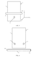
FIG. 1 is schematic structural diagram of an electronic apparatus according toEmbodiment 1 of the present invention; -
FIG. 2 is a schematic diagram of a magnetic pen serving as an information input device according toEmbodiment 1 of the present invention; -
FIG. 3 is a schematic diagram of a magnetic pen serving as a direction control device according toEmbodiment 1 of the present invention; -
FIG. 4 is a schematic structural diagram of an electronic apparatus according toEmbodiment 2 of the present invention; -
FIG. 5 is a schematic diagram of a magnetic pen serving as an information input device according toEmbodiment 2 of the present invention; -
FIG. 6 is a schematic diagram of a magnetic pen serving as a direction control device according toEmbodiment 2 of the present invention; and -
FIG. 7 is a schematic diagram of a magnetic pen serving as an angle control device according toEmbodiment 2 of the present invention. - To make the objectives, technical solutions, and advantages of the present invention clearer and more comprehensible, the following further describes the present invention in detail with reference to the accompanying drawings and embodiments. It should be understood that the specific embodiments described herein are merely used to explain the present invention but are not intended to limit the present invention.
- In the embodiments of the present invention, an electronic apparatus is equipped with at least one magnetic sensor for obtaining a change of an external magnetic field and controlling content displayed on a screen according to the change; therefore, a corresponding operation may be conveniently and quickly performed only by moving a magnetic pen close to the electronic apparatus.
- The following gives a detailed description of implementation of the present invention with reference to specific embodiments. The electronic apparatus in the following embodiments may be a mobile phone, a tablet, or the like.
- As shown in
FIG. 1 to FIG. 3 , anelectronic apparatus 1 provided in this embodiment of the present invention is equipped with at least onemagnetic sensor 10 for obtaining a change of an external magnetic field and controlling content displayed on a screen according to the change. In this case, a corresponding operation may be conveniently and quickly performed only by moving amagnetic pen 2 close to theelectronic apparatus 1. In this embodiment, a long bar-shaped magnet serves as themagnetic pen 2 and a movement of themagnetic pen 2 may be monitored only by themagnetic sensor 10 inside theelectronic apparatus 1, thereby simplifying a structure of the electronic apparatus and reducing costs. - To enable the
magnetic sensor 10 to accurately obtain the change of the external magnetic field, an influence of an intrinsic magnetic field of the environment should be considered. The intrinsic magnetic field of the environment includes two parts: one is a magnetic field generated by an internal magnetic device (for example, an audio device such as a Receiver) of theelectronic apparatus 1, and the other is geomagnetic gravity. Because a position and magnitude of a gravitational force of the internal magnetic device of theelectronic apparatus 1 are fixed relative to themagnetic sensor 10, and a direction and magnitude of the geomagnetic gravity are also fixed, the influence of the gravitational force and the geomagnetic gravity may be considered during calculation and eliminated. - A method for eliminating the influence of the magnetic force of the internal device of the
electronic apparatus 1 is provided herein: all existing magnetic induction chips have a function of rectifying and calibrating themagnetic sensor 10 inside theelectronic apparatus 1. Because theelectronic apparatus 1 has a fixed internal structure, the magnetic force generated by the internal magnetic device (for example, the audio device such as the Receiver) of theelectronic apparatus 1 has a feature that: a direction and magnitude of the magnetic force generated by the internal magnetic device are both fixed relative to the magnetic sensor. All the existing magnetic induction chips have a self-calibration function. Only by shaking the electronic apparatus for several times, a value and the direction of the fixed magnetic force may be fully estimated, and an influence of this part of the magnetic force is eliminated in subsequent measurement. - A method for eliminating the influence of the geomagnetic gravity is further provided herein: the geomagnetic gravity has a feature that: an absolute direction and magnitude of the geomagnetic gravity are fixed, that is, there is always a gravitational force in an absolute direction as the electronic apparatus moves and rolls over. Therefore, before the magnetic pen moves close to the electronic apparatus, a direction of a geomagnetic force in a current state may be learned (magnitude is fixed and may be preset) only according to a current posture of the electronic apparatus determined based on current G-sensor information, and according to magnetic force measurement data obtained by the magnetic sensor. If the electronic apparatus is basically kept stationary (which may be learned according to the G-sensor information) when it is used by a user, a measuring direction of geomagnetic induction at a moment before the magnetic pen is used may be used as a reference value of a geomagnetic direction in this operation, which is deleted in a final calculation. If the user performs the operation in a vehicle, because generally the vehicle does not frequently swerve, a measurement value of the direction of the geomagnetic gravity generated at a moment before the magnetic pen moves close to the electronic apparatus may be used as a reference calibration value. In addition, considering that the magnetic force of the magnetic pen is much greater than the geomagnetic force, the influence on the final calculation result is limited even if there is some interference.
- Specifically, when the
magnetic pen 2 is perpendicular or nearly perpendicular to the screen of theelectronic apparatus 1 and serves as an information input device, one magnetic pole of themagnetic pen 1 serves as aninput end 21, and themagnetic sensor 10 inputs information according to a track formed by a movement of theinput end 21 close to the screen in the air. The other magnetic pole of themagnetic pen 2 serves as a deletingend 22; themagnetic sensor 10 selects and deletes the information according to a track formed by a movement of the deletingend 22 close to the screen in the air. To delete the information, it is only required to invert themagnetic pen 2 to perform a corresponding operation, which is more convenient and quicker. The information includes, but is not limited to, a character or an image. - For example, in an electronic apparatus system, an N pole of the magnetic pen is preset as the
input end 21. When holding themagnetic pen 2 perpendicular to the screen of theelectronic apparatus 1, with the N pole close to the screen of theelectronic apparatus 1 and an S pole far away from the screen of theelectronic apparatus 1, the user may perform such an operation as writing a character or drawing a picture. The user moves themagnetic pen 2 in the air, and themagnetic sensor 10 reads data on three magnetic induction axes (x, y, and z) at regular intervals (for example, 10 ms) and determines a specific spatial coordinate of the N pole of the magnetic pen according to the data. As themagnetic pen 2 moves, the data on the three axes (x, y, and z) that is read by themagnetic sensor 10 is also changing; a movement track of themagnetic pen 2 in the air is formed by connecting spatial coordinates gathered at each time point; and then an input function may be completed by using this track as input information of a handwriting input module. - For another example, in the electronic apparatus system, the S pole of the magnetic pen is preset as the deleting
end 22. When the user holds themagnetic pen 2 perpendicular to the screen of theelectronic apparatus 1, with the S pole close to the screen of theelectronic apparatus 1 and the N pole far away from the screen of theelectronic apparatus 1, the character or image may be deleted. In this case, themagnetic pen 2 is equivalent to an eraser. Themagnetic sensor 10 reads the data on the three magnetic induction axes (x, y, and z) at regular intervals (for example, 10 ms) and determines a specific spatial coordinate of the S pole of the magnetic pen according to the data. As themagnetic pen 2 moves, the data on the three axes (x, y, and z) that is read by themagnetic sensor 10 is also changing; the movement track of themagnetic pen 2 in the air is formed by connecting the spatial coordinates gathered at each time point; and then an information deleting module may delete the information such as the character or image on the movement track. - This embodiment of the present invention determines a positional relationship of the
magnetic pen 2 relative to theelectronic apparatus 1 according to a feature of the data read by the magnetic induction chip. As mentioned above, themagnetic pen 2 is made of a long bar-shaped magnet, which has a feature that the magnetic force near the magnetic poles on both ends of the magnetic pen is very strong and has specific directivity while the magnetic force immediately weakens in a place a little farther from the magnetic poles. - When the user holds the
magnetic pen 2 perpendicular to the screen of theelectronic apparatus 1, with the N pole close to the screen of theelectronic apparatus 1, an obvious downward magnetic force perpendicular to the screen of theelectronic apparatus 1 is imposed on themagnetic sensor 10, where magnetism of the magnetic sensor may be considered the same as that of the N pole of the magnetic pen. In this case, a feature of the current magnetic force induced by the magnetic sensor is that data on the Z axis (perpendicular to the screen of the electronic apparatus and facing upward) is obviously negative. If this condition is met, it may be determined that the user operates the magnetic pen in a perpendicular direction and puts the N pole close to the electronic apparatus. At this time, the magnetic pen may be used to enter various information. - Likewise, when the user holds the
magnetic pen 2 perpendicular to the screen of theelectronic apparatus 1, with the S pole close to the screen of theelectronic apparatus 1, an obvious upward magnetic force perpendicular to the screen of theelectronic apparatus 1 is imposed on themagnetic sensor 10, where the magnetism of the magnetic sensor is opposite to that of the N pole of the magnetic pen. In this case, a feature of the current magnetic force induced by the magnetic sensor is that data on the Z axis (perpendicular to the screen of the electronic apparatus and facing upward) is obviously positive. If this condition is met, it may be determined that the user operates the magnetic pen in a perpendicular direction and puts the S pole close to the electronic apparatus. At this time, the magnetic pen may be used to delete the various information. - After the user completes an operation and before the users performs a next operation, to ensure that the movement of the
magnetic pen 2 between the two operations are not misjudged by theelectronic apparatus 1, areset key 3 that separates two pieces of successive information so that the two pieces of successive information may be successively entered or deleted is provided in theelectronic apparatus 1, where a function of thereset key 3 is to verify when the movement of the magnetic pen starts to be determined. When the user presses thereset key 3, that is, enabling a function for monitoring the movement of themagnetic pen 2, an internal processor of theelectronic apparatus 1 reads the data of themagnetic sensor 10 and determines a current position and a current state of the magnetic pen, and the position and the state are used as an original state, and then the internal processor of the electronic apparatus obtains related data by using themagnetic sensor 10 when the user moves themagnetic pen 2, implementing verification of an original movement position of the magnetic pen. When the user wants to perform a new operation, for example, when the user wants to enter a second character after entering one character, the user may press thereset key 3 again to temporarily disable the function of monitoring the movement of the magnetic pen; and the user can enable the function again when the user takes themagnetic pen 2 back to the original position, that is, pressing thereset key 3 again. - In this embodiment of the present invention, a reset time or a reset distance may be set between two pieces of successive information, which are to be entered or deleted, to distinguish them. The reset time is generally set to 0.2-0.4s, and the reset distance is generally set to 0.5-1.5 cm. For example, when wanting to enter a next character after entering one character, the user pauses for 0.3s in a position where the previous character is entered, and the
magnetic sensor 10 deems that the user is to enter the next character. Alternatively, when wanting to enter a next character after entering one character, the user puts themagnetic pen 2 back to a former position after lifting themagnetic pen 2 upward for 1 cm, and themagnetic sensor 10 deems that the user is to enter the next character. - To enter or delete the information here, it is necessary to move the
magnetic pen 2. The movement of themagnetic pen 2 causes a change of the data read on the three axes of the magnetic sensor. In fact, a spatial position and the movement track of themagnetic pen 2 may be determined according to magnetic data on the three axes (X/Y/Z) of the magnetic sensor. - The
magnetic pen 2 provided in this embodiment of the present invention further has a direction control function. Themagnetic pen 2 serves as a direction control device when it is parallel or nearly parallel to the screen of theelectronic apparatus 1. When themagnetic pen 2 moves upwards, downwards, forwards, backwards, leftwards, or rightwards, themagnetic sensor 10 performs corresponding direction control for the content (for example, a 3D picture) displayed on the screen according to the change of the magnetic field generated by the movement of themagnetic pen 2. At this time, themagnetic sensor 10 obtains the change of the magnetic field generated by an upward, downward, forward, backward, leftward, or rightward movement of themagnetic pen 2, determines a movement direction of themagnetic pen 2, and implements three-dimensional direction control. The direction control is intuitive and user experience is improved. - For example, when the
magnetic sensor 10 determines that themagnetic pen 2 is currently parallel to the screen of theelectronic apparatus 1, it indicates that the user wants to control a direction. In this case, themagnetic sensor 10 reads the data on the three magnetic induction axes (x, y, and z) at regular intervals (for example, 10 ms) and determines the specific spatial coordinates of the N pole and the S pole of the magnetic pen according to the data, so as to obtain current spatial positions of the N pole and the S pole of the magnetic pen. When the user moves up themagnetic pen 2 parallel to the screen of theelectronic apparatus 1, themagnetic sensor 10 determines that the spatial position of themagnetic pen 2 moves upward according to changes of the spatial positions of the N pole and the S pole of the magnetic pen, thereby controlling the content (for example, the 3D picture) displayed on the screen to move upward. Likewise, control operations in the downward, leftward, and rightward directions performed by the user may be determined. - To obtain a change of an external magnetic field more accurately, a first
magnetic sensor 11 and a secondmagnetic sensor 12 are provided within theelectronic apparatus 1, where the firstmagnetic sensor 11 and the secondmagnetic sensor 12 are respectively located on the left side and the right side of theelectronic apparatus 1, as shown inFIG. 4 to FIG. 7 . Certainly, more magnetic sensors indicate more accurate operations and control. When themagnetic pen 2 is parallel or nearly parallel to a screen of theelectronic apparatus 1, data on a Z axis that is read by one of the two magnetic sensors is positive while data on a Z axis that is read by the other magnetic sensor is negative; determination may be made based on this condition. - For example, if the first
magnetic sensor 11 and the secondmagnetic sensor 12 determine that themagnetic pen 2 is currently parallel to the screen of theelectronic apparatus 1, it indicates that a user wants to control a direction. In this case, the firstmagnetic sensor 11 and the secondmagnetic sensor 12 read data on three magnetic induction axes (x, y, and z) at regular intervals (for example, 10 ms) and determine specific spatial coordinates of an N pole and an S pole of the magnetic pen according to the data, thereby obtaining current spatial positions of the N pole and the S pole of the magnetic pen. When the user moves forward themagnetic pen 2 parallel to the screen of theelectronic apparatus 1, the firstmagnetic sensor 11 and the secondmagnetic sensor 12 determine that the spatial position of themagnetic pen 2 moves forward according to changes of the spatial positions of the N pole and the S pole of the magnetic pen, thereby controlling content (for example, a 3D picture) displayed on the screen to move forward. Likewise, control operations in the downward, leftward, and rightward directions performed by the user may be determined. - In addition, when the user holds the
magnetic pen 2 perpendicular to the screen of theelectronic apparatus 1, with the N pole close to the screen of theelectronic apparatus 1, features of a current magnetic force induced by the two magnetic sensors at this time are that data on the Z axis (perpendicular to the screen of the electronic apparatus and facing upward) is obviously negative, and on the X axis, a value read by the firstmagnetic sensor 11 located on the left side of the screen is a negative value while a value read by the secondmagnetic sensor 12 located on the right side of the screen is a positive value, as shown inFIG. 5 . If the three conditions are met, it may be determined that the user operates themagnetic pen 2 in a perpendicular direction and puts the N pole close to theelectronic apparatus 1. At this time, themagnetic pen 2 may be used to enter various information. The information includes, but is not limited to, a character or an image. - For example, in an electronic apparatus system, the N pole of the magnetic pen is preset as an
input end 21. When the user holds themagnetic pen 2 perpendicular to the screen of theelectronic apparatus 1, with the N pole close to the screen of theelectronic apparatus 1 and the S pole far away from the screen of theelectronic apparatus 1, the user may perform such an operation as writing a character or drawing a picture. The user moves themagnetic pen 2 in the air, and the magnetic sensor reads the data on the three magnetic induction axes (x, y, and z) at regular intervals (for example, 10 ms) and determines the specific spatial coordinate of the N pole of the magnetic pen according to the data. As themagnetic pen 2 moves, the data on the three axes (x, y, and z) that is read by the magnetic sensor is also changing; a movement track of themagnetic pen 2 in the air is formed by connecting the spatial coordinates gathered at each time point; and then an input function may be completed by using this track as input information of a handwriting input module. - Likewise, when the user holds the
magnetic pen 2 perpendicular to the screen of theelectronic apparatus 1, with the S pole close to the screen of theelectronic apparatus 1, features of a current magnetic force induced by the two magnetic sensors at this time are that data on the Z axis(perpendicular to the screen of the electronic apparatus and facing upward) is obviously positive, and on the X axis, a value read by the firstmagnetic sensor 11 located on the left side of the screen is a positive value while a value read by the secondmagnetic sensor 12 located on the right side of the screen is a negative value. If the three conditions are met, it may be determined that the user operates the magnetic pen in the perpendicular direction and puts the S pole close to the electronic apparatus. At this time, the magnetic pen may be used to delete the various information. - For another example, in the electronic apparatus system, the S pole of the magnetic pen is preset as a deleting
end 22. When the user holds themagnetic pen 2 perpendicular to the screen of theelectronic apparatus 1, with the S pole close to the screen of theelectronic apparatus 1 and the N pole far away from the screen of theelectronic apparatus 1, the character or image may be deleted. In this case, the magnetic pen is equivalent to an eraser. The magnetic sensor reads the data on the three magnetic induction axes (x, y, and z) at regular intervals (for example, 10 ms) and determines the specific spatial coordinate of the S pole of the magnetic pen according to the data. As themagnetic pen 2 moves, the data on the three axes (x, y, and z) that is read by the magnetic sensor is also changing; the movement track of themagnetic pen 2 in the air is formed by connecting the spatial coordinates gathered at each time point; and then an information deleting module may delete the information such as the character or image on the movement track. - In addition, when the
magnetic pen 2 is parallel or nearly parallel to the screen of theelectronic apparatus 1, themagnetic pen 2 is further used as an angle control device. When themagnetic pen 2 rotates clockwise or counterclockwise in an original position, the firstmagnetic sensor 11 and the secondmagnetic sensor 12 perform corresponding angle control for the content displayed on the screen according to the change of the magnetic field generated by rotation of the magnetic pen. When the magnetic pen deflects from a horizontal direction shown inFIG. 6 to an inclined direction shown inFIG. 7 , the two magnetic sensors separately determine relative spatial positions of the two magnetic poles because the firstmagnetic sensor 11 on the left side of theelectronic apparatus 1 is mainly affected by the N pole while the secondmagnetic sensor 12 on the right side is mainly affected by the S pole; and a rough deflecting direction and deflecting angle of themagnetic pen 2 can be determined by connecting the two relative positions and comparing the two relative positions with a horizontal line. Accordingly, an angle control module is provided inside the electronic apparatus to control an angle of the content displayed on the screen. - In this embodiment of the present invention, an electronic apparatus is equipped with at least one magnetic sensor for obtaining a change of an external magnetic field and controlling content displayed on a screen according to the change; therefore, a corresponding operation may be conveniently and quickly performed only by moving a magnetic pen close to the electronic apparatus. The foregoing magnetic pen serves as a direction control device when it is parallel or nearly parallel to the screen of the electronic apparatus. The magnetic sensor obtains the change of the magnetic field generated by an upward, downward, forward, backward, leftward, or rightward movement of the magnetic pen, determines a movement direction of the magnetic pen, and implements three-dimensional direction control. The direction control is intuitive and user experience is improved. In addition, a long bar-shaped magnet serves as the magnetic pen and a movement condition of the magnetic pen may be monitored only by the magnetic sensor inside the electronic apparatus, thereby simplifying a structure of the electronic apparatus and reducing costs.
- The foregoing descriptions are merely exemplary embodiments of the present invention, but are not intended to limit the present invention. Any modification, equivalent replacement, or improvement made without departing from the spirit and principle of the present invention should fall within the protection scope of the present invention.
Claims (9)
- An electronic apparatus, wherein the electronic apparatus is equipped with at least one magnetic sensor for obtaining a change of an external magnetic field and controlling content displayed on a screen according to the change.
- The electronic apparatus according to claim 1, wherein the external magnetic field is changed by moving or rotating a long bar-shaped magnetic pen, and both ends of the magnetic pen are magnetic poles with opposite magnetism.
- The electronic apparatus according to claim 2, wherein the magnetic pen serves as an information input device when the magnetic pen is perpendicular or nearly perpendicular to the screen; one magnetic pole of the magnetic pen serves as an input end at this time, and the magnetic sensor inputs the information according to a track formed by a movement of the input end close to the screen in the air.
- The electronic apparatus according to claim 3, wherein the magnetic pen serves as an information deleting device when the magnetic pen is perpendicular or nearly perpendicular to the screen; the other magnetic pole of the magnetic pen serves as a deleting end at this time, and the magnetic sensor selects and deletes the information according to a track formed by a movement of the deleting end close to the screen in the air.
- The electronic apparatus according to claim 3 or 4, wherein the electronic apparatus is equipped with a reset key, which is configured to enter or delete two pieces of successive information separately.
- The electronic apparatus according to claim 3 or 4, wherein a reset time or a reset distance is set between two pieces of successive information, which are to be entered or deleted, to distinguish them.
- The electronic apparatus according to claim 1, wherein a magnetic pen serves as a direction control device when the magnetic pen is parallel or nearly parallel to the screen; the magnetic sensor performs corresponding direction control for the content displayed on the screen according to a magnetic field change generated by a movement of the magnetic pen, when the magnetic pen moves upwards, downwards, forwards, backwards, leftwards, or rightwards.
- The electronic apparatus according to claim 1, 2, 3, 4, or 7, wherein the number of the magnetic sensors is two, which are respectively located on the left side and the right side of the electronic apparatus.
- The electronic apparatus according to claim 8, wherein the magnetic pen serves as an angle control device when the magnetic pen is parallel or nearly parallel to the screen; and the magnetic sensors on the left side and the right side perform corresponding angle control for the content displayed on the screen according to a magnetic field change generated by rotation of the magnetic pen, when the magnetic pen rotates clockwise or counterclockwise in an original position.
Applications Claiming Priority (2)
| Application Number | Priority Date | Filing Date | Title |
|---|---|---|---|
| CN201210015796.9A CN102609163B (en) | 2012-01-18 | 2012-01-18 | A kind of electronic installation |
| PCT/CN2013/070676 WO2013107382A1 (en) | 2012-01-18 | 2013-01-18 | Electronic device |
Publications (2)
| Publication Number | Publication Date |
|---|---|
| EP2806342A1 true EP2806342A1 (en) | 2014-11-26 |
| EP2806342A4 EP2806342A4 (en) | 2015-04-01 |
Family
ID=46526587
Family Applications (1)
| Application Number | Title | Priority Date | Filing Date |
|---|---|---|---|
| EP13738522.5A Ceased EP2806342A4 (en) | 2012-01-18 | 2013-01-18 | Electronic device |
Country Status (4)
| Country | Link |
|---|---|
| US (1) | US20140327659A1 (en) |
| EP (1) | EP2806342A4 (en) |
| CN (1) | CN102609163B (en) |
| WO (1) | WO2013107382A1 (en) |
Cited By (1)
| Publication number | Priority date | Publication date | Assignee | Title |
|---|---|---|---|---|
| EP3267299A1 (en) * | 2016-07-05 | 2018-01-10 | Lg Electronics Inc. | Mobile terminal and method for controlling the same |
Families Citing this family (8)
| Publication number | Priority date | Publication date | Assignee | Title |
|---|---|---|---|---|
| CN102609163B (en) * | 2012-01-18 | 2015-11-25 | 华为终端有限公司 | A kind of electronic installation |
| TWI471764B (en) * | 2012-02-20 | 2015-02-01 | Qisda Corp | Coordinate sensing system, coordinate sensing method and display system |
| KR102106779B1 (en) * | 2013-06-28 | 2020-05-06 | 삼성전자주식회사 | Method for processing pen input and apparatus for the same |
| CN105513330A (en) * | 2014-09-22 | 2016-04-20 | 联想(北京)有限公司 | Command generation method, electronic equipment and wearable apparatus |
| KR20170138279A (en) | 2016-06-07 | 2017-12-15 | 엘지전자 주식회사 | Mobile terminal and method for controlling the same |
| JP7003877B2 (en) * | 2018-08-23 | 2022-01-21 | 日本電信電話株式会社 | Input device for touch panel |
| CN109542254B (en) * | 2018-10-31 | 2022-03-22 | 广州三星通信技术研究有限公司 | Stylus pen and electronic device comprising same |
| EP4375812A1 (en) * | 2022-11-24 | 2024-05-29 | Advanced Magnetic Interaction, AMI | Detection of a location of a user-borne device with a plurality of magnetometers |
Citations (6)
| Publication number | Priority date | Publication date | Assignee | Title |
|---|---|---|---|---|
| US20020134594A1 (en) * | 2000-11-22 | 2002-09-26 | Brian Taylor | Stylus input device utilizing a permanent magnet |
| US20030095115A1 (en) * | 2001-11-22 | 2003-05-22 | Taylor Brian | Stylus input device utilizing a permanent magnet |
| US20050231309A1 (en) * | 2004-04-15 | 2005-10-20 | Lee Kun T | Board having magnetic members |
| US20070242075A1 (en) * | 2006-03-22 | 2007-10-18 | Quanta Computer Inc. | Screen control system |
| US20090279783A1 (en) * | 2000-03-07 | 2009-11-12 | Apple Inc. | Method and apparatus for acquiring and organizing ink information in pen-aware computer systems |
| US20110190060A1 (en) * | 2010-02-02 | 2011-08-04 | Deutsche Telekom Ag | Around device interaction for controlling an electronic device, for controlling a computer game and for user verification |
Family Cites Families (10)
| Publication number | Priority date | Publication date | Assignee | Title |
|---|---|---|---|---|
| EP0187372B1 (en) * | 1984-12-28 | 1990-08-08 | Wacom Company, Ltd. | Position detecting device |
| US5434370A (en) * | 1993-11-05 | 1995-07-18 | Microfield Graphics, Inc. | Marking system with pen-up/pen-down tracking |
| US5684396A (en) * | 1996-03-05 | 1997-11-04 | Hughes Aircraft Company | Localizing magnetic dipoles using spatial and temporal processing of magnetometer data |
| JP4522129B2 (en) * | 2004-03-31 | 2010-08-11 | キヤノン株式会社 | Image processing method and image processing apparatus |
| US8674946B2 (en) * | 2007-10-04 | 2014-03-18 | Alpine Electronics, Inc. | Method and apparatus for controlling timing of status change of electronics apparatus based on user's finger location and input speed |
| CN101825959A (en) * | 2009-03-05 | 2010-09-08 | 鸿富锦精密工业(深圳)有限公司 | Electromagnetic input device |
| US8773121B2 (en) * | 2010-06-02 | 2014-07-08 | Sony Computer Entertainment Inc. | Magnetic input for computer device |
| JP5459795B2 (en) * | 2011-06-06 | 2014-04-02 | 株式会社ワコム | Electronics |
| CN102314274B (en) * | 2011-06-30 | 2014-12-17 | 汉王科技股份有限公司 | Bimodule input device and method for sending data by using same |
| CN102609163B (en) * | 2012-01-18 | 2015-11-25 | 华为终端有限公司 | A kind of electronic installation |
-
2012
- 2012-01-18 CN CN201210015796.9A patent/CN102609163B/en active Active
-
2013
- 2013-01-18 WO PCT/CN2013/070676 patent/WO2013107382A1/en active Application Filing
- 2013-01-18 EP EP13738522.5A patent/EP2806342A4/en not_active Ceased
-
2014
- 2014-07-16 US US14/332,605 patent/US20140327659A1/en not_active Abandoned
Patent Citations (6)
| Publication number | Priority date | Publication date | Assignee | Title |
|---|---|---|---|---|
| US20090279783A1 (en) * | 2000-03-07 | 2009-11-12 | Apple Inc. | Method and apparatus for acquiring and organizing ink information in pen-aware computer systems |
| US20020134594A1 (en) * | 2000-11-22 | 2002-09-26 | Brian Taylor | Stylus input device utilizing a permanent magnet |
| US20030095115A1 (en) * | 2001-11-22 | 2003-05-22 | Taylor Brian | Stylus input device utilizing a permanent magnet |
| US20050231309A1 (en) * | 2004-04-15 | 2005-10-20 | Lee Kun T | Board having magnetic members |
| US20070242075A1 (en) * | 2006-03-22 | 2007-10-18 | Quanta Computer Inc. | Screen control system |
| US20110190060A1 (en) * | 2010-02-02 | 2011-08-04 | Deutsche Telekom Ag | Around device interaction for controlling an electronic device, for controlling a computer game and for user verification |
Non-Patent Citations (3)
| Title |
|---|
| "MagnetMeter on iPhone 3GS", , 23 December 2011 (2011-12-23), XP055146362, Retrieved from the Internet: URL:http://web.archive.org/web/20111223150105/http://www.plaincode.com/products/magnetmeter [retrieved on 2014-10-14] & Peter Breitling: "iPhone 3GS as Vector Magnetometer", , 22 December 2009 (2009-12-22), XP054975548, Retrieved from the Internet: URL:http://www.youtube.com/watch?v=tcIe0kWm9rg [retrieved on 2014-10-13] * |
| HAMED KETABDAR ET AL: "MagiTact: interaction with mobile devices based on compass (magnetic) sensor", PROCEEDINGS OF THE 14TH ACM INTERNATIONAL CONFERENCE ON INTELLIGENT USER INTERFACES ; FEBRUARY 7-10, 2010, HONG KONG, CHINA, ACM, NEW YORK, NY, 7 February 2010 (2010-02-07), pages 413-414, XP002685703, DOI: 10.1145/1719970.1720048 ISBN: 978-1-60558-515-4 * |
| See also references of WO2013107382A1 * |
Cited By (2)
| Publication number | Priority date | Publication date | Assignee | Title |
|---|---|---|---|---|
| EP3267299A1 (en) * | 2016-07-05 | 2018-01-10 | Lg Electronics Inc. | Mobile terminal and method for controlling the same |
| US10055059B2 (en) | 2016-07-05 | 2018-08-21 | Lg Electronics Inc. | Mobile terminal and method for controlling the same |
Also Published As
| Publication number | Publication date |
|---|---|
| EP2806342A4 (en) | 2015-04-01 |
| CN102609163B (en) | 2015-11-25 |
| US20140327659A1 (en) | 2014-11-06 |
| WO2013107382A1 (en) | 2013-07-25 |
| CN102609163A (en) | 2012-07-25 |
Similar Documents
| Publication | Publication Date | Title |
|---|---|---|
| EP2806342A1 (en) | Electronic device | |
| KR102129374B1 (en) | Method for providing user interface, machine-readable storage medium and portable terminal | |
| KR102113674B1 (en) | Apparatus, method and computer readable recording medium for selecting objects displayed on an electronic device using a multi touch | |
| US8633909B2 (en) | Information processing apparatus, input operation determination method, and input operation determination program | |
| US9201521B2 (en) | Storing trace information | |
| JP6100287B2 (en) | Terminal multiple selection operation method and terminal | |
| KR102092132B1 (en) | Electronic apparatus providing hovering input effect and control method thereof | |
| US9459704B2 (en) | Method and apparatus for providing one-handed user interface in mobile device having touch screen | |
| US20130215018A1 (en) | Touch position locating method, text selecting method, device, and electronic equipment | |
| US20140354553A1 (en) | Automatically switching touch input modes | |
| US20140331146A1 (en) | User interface apparatus and associated methods | |
| KR102155836B1 (en) | Mobile terminal for controlling objects display on touch screen and method therefor | |
| US10116787B2 (en) | Electronic device, control method, and non-transitory storage medium | |
| KR20140076261A (en) | Terminal and method for providing user interface using pen | |
| US20140337720A1 (en) | Apparatus and method of executing function related to user input on screen | |
| KR102186815B1 (en) | Method, apparatus and recovering medium for clipping of contents | |
| US20150002417A1 (en) | Method of processing user input and apparatus using the same | |
| KR20140100705A (en) | Method and apparatus for controlling operation of touch key | |
| US9395838B2 (en) | Input device, input control method, and input control program | |
| US9261996B2 (en) | Mobile terminal including touch screen supporting multi-touch input and method of controlling the same | |
| US20140223370A1 (en) | Mobile electronic device, method for controlling mobile electronic device, program, and information storage medium | |
| KR20140029608A (en) | Coordinate sensing apparatus and method for controlling thereof | |
| KR20150008963A (en) | Mobile terminal and method for controlling screen | |
| KR20140137629A (en) | Mobile terminal for detecting earphone connection and method therefor | |
| CN103870013B (en) | Information processing method, device and electronic equipment |
Legal Events
| Date | Code | Title | Description |
|---|---|---|---|
| PUAI | Public reference made under article 153(3) epc to a published international application that has entered the european phase |
Free format text: ORIGINAL CODE: 0009012 |
|
| 17P | Request for examination filed |
Effective date: 20140717 |
|
| AK | Designated contracting states |
Kind code of ref document: A1 Designated state(s): AL AT BE BG CH CY CZ DE DK EE ES FI FR GB GR HR HU IE IS IT LI LT LU LV MC MK MT NL NO PL PT RO RS SE SI SK SM TR |
|
| RIC1 | Information provided on ipc code assigned before grant |
Ipc: G06F 3/046 20060101AFI20141110BHEP Ipc: G06F 3/0354 20130101ALN20141110BHEP Ipc: G06F 3/0346 20130101ALN20141110BHEP |
|
| A4 | Supplementary search report drawn up and despatched |
Effective date: 20150302 |
|
| RIC1 | Information provided on ipc code assigned before grant |
Ipc: G06F 3/0354 20130101ALN20150224BHEP Ipc: G06F 3/0346 20130101ALN20150224BHEP Ipc: G06F 3/046 20060101AFI20150224BHEP |
|
| DAX | Request for extension of the european patent (deleted) | ||
| 17Q | First examination report despatched |
Effective date: 20170614 |
|
| RAP1 | Party data changed (applicant data changed or rights of an application transferred) |
Owner name: HUAWEI DEVICE (DONGGUAN) CO., LTD. |
|
| RAP1 | Party data changed (applicant data changed or rights of an application transferred) |
Owner name: HUAWEI DEVICE CO., LTD. |
|
| REG | Reference to a national code |
Ref country code: DE Ref legal event code: R003 |
|
| STAA | Information on the status of an ep patent application or granted ep patent |
Free format text: STATUS: THE APPLICATION HAS BEEN REFUSED |
|
| 18R | Application refused |
Effective date: 20190921 |