EP2805179B1 - Optical system for range finding - Google Patents
Optical system for range finding Download PDFInfo
- Publication number
- EP2805179B1 EP2805179B1 EP13701587.1A EP13701587A EP2805179B1 EP 2805179 B1 EP2805179 B1 EP 2805179B1 EP 13701587 A EP13701587 A EP 13701587A EP 2805179 B1 EP2805179 B1 EP 2805179B1
- Authority
- EP
- European Patent Office
- Prior art keywords
- laser pulses
- wavelength
- series
- different
- waveguides
- Prior art date
- Legal status (The legal status is an assumption and is not a legal conclusion. Google has not performed a legal analysis and makes no representation as to the accuracy of the status listed.)
- Active
Links
- 230000003287 optical effect Effects 0.000 title claims description 295
- 230000001934 delay Effects 0.000 claims description 52
- 230000003111 delayed effect Effects 0.000 claims description 31
- 238000004590 computer program Methods 0.000 claims description 30
- 238000000034 method Methods 0.000 claims description 28
- 239000013307 optical fiber Substances 0.000 description 43
- 239000000835 fiber Substances 0.000 description 30
- 238000010586 diagram Methods 0.000 description 13
- 230000003595 spectral effect Effects 0.000 description 12
- 238000001514 detection method Methods 0.000 description 6
- 230000006870 function Effects 0.000 description 6
- 238000005286 illumination Methods 0.000 description 6
- 230000003321 amplification Effects 0.000 description 5
- 238000003199 nucleic acid amplification method Methods 0.000 description 5
- 229910052761 rare earth metal Inorganic materials 0.000 description 4
- 239000004065 semiconductor Substances 0.000 description 4
- 238000005259 measurement Methods 0.000 description 3
- 238000002366 time-of-flight method Methods 0.000 description 3
- 230000015556 catabolic process Effects 0.000 description 2
- 238000006731 degradation reaction Methods 0.000 description 2
- 230000004927 fusion Effects 0.000 description 2
- 230000009022 nonlinear effect Effects 0.000 description 2
- 210000000056 organ Anatomy 0.000 description 2
- 230000000737 periodic effect Effects 0.000 description 2
- 238000005086 pumping Methods 0.000 description 2
- 229910052691 Erbium Inorganic materials 0.000 description 1
- 229910052779 Neodymium Inorganic materials 0.000 description 1
- 229910052769 Ytterbium Inorganic materials 0.000 description 1
- 238000005452 bending Methods 0.000 description 1
- 239000000969 carrier Substances 0.000 description 1
- 238000004891 communication Methods 0.000 description 1
- 230000008878 coupling Effects 0.000 description 1
- 238000010168 coupling process Methods 0.000 description 1
- 238000005859 coupling reaction Methods 0.000 description 1
- 230000003247 decreasing effect Effects 0.000 description 1
- 230000001419 dependent effect Effects 0.000 description 1
- 239000006185 dispersion Substances 0.000 description 1
- 230000000694 effects Effects 0.000 description 1
- 230000008030 elimination Effects 0.000 description 1
- 238000003379 elimination reaction Methods 0.000 description 1
- 238000013467 fragmentation Methods 0.000 description 1
- 238000006062 fragmentation reaction Methods 0.000 description 1
- 230000003455 independent Effects 0.000 description 1
- 238000009434 installation Methods 0.000 description 1
- 238000004519 manufacturing process Methods 0.000 description 1
- 230000000116 mitigating effect Effects 0.000 description 1
- 230000002085 persistent effect Effects 0.000 description 1
- 230000001902 propagating effect Effects 0.000 description 1
- 238000005070 sampling Methods 0.000 description 1
- 239000007787 solid Substances 0.000 description 1
- 238000012421 spiking Methods 0.000 description 1
Images


Classifications
-
- G—PHYSICS
- G01—MEASURING; TESTING
- G01S—RADIO DIRECTION-FINDING; RADIO NAVIGATION; DETERMINING DISTANCE OR VELOCITY BY USE OF RADIO WAVES; LOCATING OR PRESENCE-DETECTING BY USE OF THE REFLECTION OR RERADIATION OF RADIO WAVES; ANALOGOUS ARRANGEMENTS USING OTHER WAVES
- G01S7/00—Details of systems according to groups G01S13/00, G01S15/00, G01S17/00
- G01S7/48—Details of systems according to groups G01S13/00, G01S15/00, G01S17/00 of systems according to group G01S17/00
- G01S7/481—Constructional features, e.g. arrangements of optical elements
-
- G—PHYSICS
- G01—MEASURING; TESTING
- G01S—RADIO DIRECTION-FINDING; RADIO NAVIGATION; DETERMINING DISTANCE OR VELOCITY BY USE OF RADIO WAVES; LOCATING OR PRESENCE-DETECTING BY USE OF THE REFLECTION OR RERADIATION OF RADIO WAVES; ANALOGOUS ARRANGEMENTS USING OTHER WAVES
- G01S17/00—Systems using the reflection or reradiation of electromagnetic waves other than radio waves, e.g. lidar systems
- G01S17/02—Systems using the reflection of electromagnetic waves other than radio waves
- G01S17/06—Systems determining position data of a target
- G01S17/08—Systems determining position data of a target for measuring distance only
-
- G—PHYSICS
- G01—MEASURING; TESTING
- G01S—RADIO DIRECTION-FINDING; RADIO NAVIGATION; DETERMINING DISTANCE OR VELOCITY BY USE OF RADIO WAVES; LOCATING OR PRESENCE-DETECTING BY USE OF THE REFLECTION OR RERADIATION OF RADIO WAVES; ANALOGOUS ARRANGEMENTS USING OTHER WAVES
- G01S7/00—Details of systems according to groups G01S13/00, G01S15/00, G01S17/00
- G01S7/48—Details of systems according to groups G01S13/00, G01S15/00, G01S17/00 of systems according to group G01S17/00
- G01S7/483—Details of pulse systems
- G01S7/484—Transmitters
-
- G—PHYSICS
- G01—MEASURING; TESTING
- G01S—RADIO DIRECTION-FINDING; RADIO NAVIGATION; DETERMINING DISTANCE OR VELOCITY BY USE OF RADIO WAVES; LOCATING OR PRESENCE-DETECTING BY USE OF THE REFLECTION OR RERADIATION OF RADIO WAVES; ANALOGOUS ARRANGEMENTS USING OTHER WAVES
- G01S7/00—Details of systems according to groups G01S13/00, G01S15/00, G01S17/00
- G01S7/48—Details of systems according to groups G01S13/00, G01S15/00, G01S17/00 of systems according to group G01S17/00
- G01S7/483—Details of pulse systems
- G01S7/486—Receivers
Definitions
- the present invention generally relates to the field of range finding, or surveying. Specifically, the present invention relates to optical systems for distance measuring and methods for generating laser pulses and receiving laser pulses suitable for use in distance measuring.
- Range finding or surveying involves the determination of unknown positions, surfaces or volumes of objects using measurements of angles and distances.
- the determined angles and distances from a measuring instrument to points under survey may be used to calculate the coordinates of surveyed points relatively to the measuring instrument.
- the measuring instrument may include an electronic distance measuring (EDM) device.
- EDM electronic distance measuring
- a light beam is emitted as a light pulse towards a target or object, and light reflected by the target is subsequently detected at the measuring instrument, e.g. comprising an optical surveying instrument such as a total station.
- Processing of the detected signal may enable determination of distance to the target by means of, e.g., time-of-flight (TOF) or phase modulation techniques.
- TOF time-of-flight
- phase modulation techniques e.g., the TOF of a light pulse that travels from the measuring instrument, i.e. the EDM device, to a target or object, is reflected at the target or object, and returns to the measuring instrument, is determined.
- the distance between the measuring instrument and the target or object may then be calculated.
- the power loss of the received signal may determine the maximum possible operating range for which EDM can be performed.
- the power of the light beam that is transmitted towards the target or object must be increased, or be made as large as possible in order to maximize the operating range.
- the light beam is emitted as a periodic train of short laser pulses with a relatively low repetition rate.
- Using short pulses with a predefined pulse shape is required for achieving a high distance resolution characteristics, i.e. reduced error in the value of measured distance.
- Utilizing pulse trains with low repetiton rate helps to avoid ambiguity in the measurements of long distances as well as to maintain the average power of the light beam at a moderate level.
- the average power of the light beam should not exceed about 10 mW for eye safety reasons.
- the transmitter part of the EDM device must be designed for generation of a pulse train with a relatively low repetition rate and high peak power in order to maximize the operating range.
- the light beam that is transmitted towards the target preferably has a wavelength within the range 1.5 ⁇ m-2 ⁇ m or a wavelength exceeding 2 ⁇ m.
- the light beam that is transmitted towards the target may be preferred to have a wavelength of 1.55 ⁇ m since this may allow utilizing a variety of relatively inexpensive optical components in the EDM device such as have been developed in the telecommunication industry for applications in optical fiber communication systems and networks.
- an EDM device based on TOF technique may be based on a master oscillator power amplifier (MOPA) configuration in the transmitter part of the EDM device.
- the transmitter part of such an EDM device typically consists of a 'seed' laser, which for example may be constituted by a semiconductor distributed feedback laser, and an erbium-doped fiber amplifier (EDFA), comprising two or more optically isolated amplification stages.
- the seed laser is driven by a pulsed electrical current having a certain repetition rate.
- the seed laser is typically capable of producing laser pulses having an optical peak power of a few tens of mW.
- the laser pulses that are generated in the seed laser are then amplified in the EDFA so as to achieve a certain optical peak power.
- the EDFA is operated in the limited range of optical pumping power, and therefore limited optical gain, such that the shape of the laser pulses amplified by the EDFA and being output from the EDFA is well preserved and free of any drastical distortions.
- optical peak power up to 1-1.5 kW for a 'standard' erbium-doped fiber being utilized in the EDFA may be achieved.
- Operating the EDFA at higher pumping power, which results in increased optical gain, and aiming at achieving the optical peak power of the laser pulses that exceeds 1-1.5 kW may lead to degradation of the EDM device performance.
- the degradation is caused by fiber non-linearity, i.e. dependency of the refractive index of the fiber on the optical field intensity of the laser pulses propagating in the fiber.
- Non-linear pulse propagation in the fiber may cause an instability process that leads to pulse shape distortions such as pulse fragmentation into several sub-pulses and strong spectral broadening of the laser pulses output from the EDFA, which laser pulses are transmitted towards the target or object, the distance to which is to be measured.
- fiber non-linearity may distort the pulse shape and therefore limit the maximum achievable peak power of the laser pulses used in EDM based on TOF technique, which in turn may possibly restrict the extent of the operating range of the EDM device.
- a custom made large ⁇ mode ⁇ area fiber may possibly be utilized in the amplification stage or stages in order to reduce the intensity of the optical field in the fiber core.
- such a type of fiber may be expensive, or may be difficult to fusion splice to a standard optical fiber - if possible at all to fusion splice to a standard optical fiber, or may entail relatively high bending losses, etc.
- Fiber non-linearity may restrict the signal-to-noise ratio achievable in the receiver part of the EDM device.
- EP1813964A2 discloses a LADAR system which includes a detector optical arrangement defining a current optical field of view.
- EP1813964A2 further discloses an illumination subsystem without moving parts which transmits pulsed illumination at different times to each of a number of illumination sub-regions af the current optical field of view, and a detection subsystem, including one or more detectors, detecting reflected illumination from a corresponding one or more detection sub-region of the current optical field of view.
- EP1813964A2 discloses that each of the detection sub-regions overlaps illumination sub-regions so that an overlap of each of the illumination sub-regions with the detection sub-region defines a LADAR image pixel of resolution finer than the detection sub-region.
- US3991318A discloses an organ array comprising a plurality of optical fibers each cut to a different length with the differences between functionally adjacent (i.e., lengthwise consecutive) fibers being uniform. US3991318A discloses that the fibers are arranged in a bundle so that one set of ends of the fibers is terminated in an input plane and the opposite set of ends is terminated in an output plane. US3991318A discloses embodiments utilizing the organ array including a passive spatial scanner, optical memory systems, an image converter, an optical sampling oscilloscope, and an x-y coordinate locater.
- US7199924B1 discloses an apparatus and a method for spectral-beam combining light from a plurality of high-power fiber lasers that use two substantially identical diffraction gratings in a parallel, mutually compensating configuration to combine a plurality of separate parallel input beams each having a slightly different successively higher wavelength into a single output beam of high quality.
- US7199924B1 further discloses a single diffraction grating used to combine a plurality of different wavelengths, wherein the input laser beams are obtained from very narrow linewidth sources to reduce chromatic dispersion.
- US7199924B1 discloses that diagnostics and adjustments of wavelengths and/or positions and angles are made dynamically in real time to maintain the combination of the plurality input beams into a single high-quality output beam.
- WO2011/000411A1 discloses a method for driving a laser diode such as to enable mitigation or elimination of so called spiking effects related to the number of injected carriers in the laser overshooting the equilibrium value at the beginning of the lasing process.
- WO2011/000411A1 discloses that in this manner, the efficiency of a master oscillator power amplifier that may be utilized in range finding applications will be improved.
- US2008074640A1 discloses methods for using spectrally separated light pulses to collect more LIDAR information are presented.
- US2008074640A1 discloses that a monochromatic pulse is transmitted to collect range information and a white pulse is transmitted a short time afterwards to collect spectral responsivity information or color of the target.
- US2008074640A1 discloses that the white light pulse is used to collect both range and spectral responsivity information of the target.
- US2008074640A1 discloses that the spectral separated laser is spatially spread in order to collect range information over more than one point at a time.
- a concern of the present invention is to provide an optical system for distance measuring that alleviates or even eliminates restrictions of the operating range for EDM related to fiber non-linearity.
- Another concern of the present invention is to provide an optical system for distance measuring that alleviates or even eliminates restrictions on signal-to-noise ratio achievable in the receiver part of the optical system related to fiber non-linearity.
- Another concern of the present invention is to provide an optical system for distance measuring that alleviates or even eliminates restrictions of the operating range for EDM related to fiber non-linearity while not requiring expensive components.
- Another concern of the present invention is to provide an optical system for distance measuring that alleviates or even eliminates restrictions on signal-to-noise ratio achievable in the receiver part of the optical system related to fiber non-linearity while not requiring expensive components.
- a gist of the present invention is to spectrally combine a train of laser pulses that are generated at a number of different wavelengths in a measuring instrument, in particular an electronic distance measuring (EDM) device.
- EDM electronic distance measuring
- Such spectral combination of a train of laser pulses generated at a number of different wavelengths may take place in an EDM device in the receiver part thereof, in the transmitter part thereof, or in both the transmitter part and the receiver part of the EDM device.
- the ocurrence of high peak optical power in optical fiber of an amplification stage in the EDM device may be decreased or even eliminated, while the signal-to-noise ratio at the receiver part of the optical system and the operating range of the optical system may be increased.
- an optical system for distance measuring comprises a transmitter and a reciver.
- the transmitter comprises a laser pulse generator adapted to generate a series of laser pulses such that the laser pulses are delayed with respect to each other, and such that each laser pulse has a wavelength different from the wavelengths of other laser pulses of the series of laser pulses, or such that at least some of the laser pulses have a wavelength different from the wavelengths of other laser pulses of the series of laser pulses.
- the transmitter may comprise an optical amplifier adapted to amplify laser pulses generated by the laser pulse generator having wavelengths within a predefined wavelength band.
- the transmitter is adapted to transmit the amplified laser pulses and/or laser pulses generated by the laser pulse generator towards a target or object.
- the receiver is adapted to receive a series of laser pulses which have been generated by reflection and/or scattering of the laser pulses transmitted by the transmitter from the target or object, respectively.
- the receiver comprises a first optical delay module adapted to delay laser pulses based on the wavelength of the respective laser pulses such that the magnitudes of delays of laser pulses having different wavelengths are different.
- the first optical delay module is arranged such that the magnitudes of delays corresponding to different wavelengths are such that the laser pulses that are output from the first optical delay module, or at least some of the laser pulses that are output from the first optical delay module, overlap or substantially overlap each other.
- the laser pulse generator may be adapted to generate a periodic train of laser pulses such that a series (finite number) of pulses is generated during each period of the pulse train, each individual laser pulse in the seriesof laser pulses having a wavelength that differs from the wavelength of other laser pulses in the series of pulses, or from the wavelength of most of the other laser pulses in the series of pulses.
- Each laser pulse in the pulse train may have a predefined pulse width. Successive laser pulses in a period of the pulse train may be delayed with respect to each other by one or a few laser pulse widths so as to mitigate or avoid laser pulse shape distortions.
- the received series of laser pulses having different wavelengths can be spectrally combined in the receiver of the optical system.
- the received signal peak power and the signal-to-noise ratio in the receiver may be increased.
- the overlapping of N laser pulses output from the first optical delay module may result in N times increased peak power of the received signal on basis of which TOF may be determined.
- the operating range of the optical system may be increased, whereby the optical system may become capable of measuring larger distances between the optical system and the target or object, corresponding to higher losses of the signal during the return trip from the optical system to the object or target and back to the optical system.
- the first optical delay module may for example comprise a wavelength demultiplexer (DEMUX) and a plurality of waveguides.
- DEMUX wavelength demultiplexer
- Each of the plurality of waveguides may correspond to one of the wavelengths of the received series of laser pulses.
- Each of the plurality of waveguides may have a predefined length.
- the wavelength DEMUX may be arranged so as to demultiplex the received series of laser pulses onto the plurality of waveguides, wherein the magnitudes of the lengths of the respective waveguides may be such that the laser pulses are coupled out from the plurality of waveguides at the same time, whereby the laser pulses that are output from the first optical delay module overlap or substantially overlap each other.
- the wavelength DEMUX may for example be based on an array waveguide grating.
- the plurality of waveguides may for example comprise a plurality of optical fibers.
- the wavelength DEMUX may have one input port and N output optical fiber ports, where N is the number of laser pulses or wavelength channels that are used in the laser pulse train generated in the laser pulse generator of the optical system's transmitter.
- N is the number of laser pulses or wavelength channels that are used in the laser pulse train generated in the laser pulse generator of the optical system's transmitter.
- each laser pulse of the respective N laser pulses may enter a corresponding optical fiber port.
- the time position of the laser pulse in each output fiber port may be related or correspond to its wavelength channel, i.e. the wavelength of the laser pulse in the output fiber port.
- the magnitudes of the lengths of the respective optical fibers may be such that laser pulses are coupled out from the plurality of optical fibers at the same time, whereby laser pulses that are output from the first optical delay module overlap each other.
- the overlapped laser pulses output from the first optical delay module may then be coupled into or impinge on a photosensor unit such as at least one photodiode in the optical system's receiver. Thereby, a received signal may be generated which may be further processed e.g. for performing EDM.
- the first optical delay module may comprise a wavelength multiplexer (MUX).
- MUX wavelength multiplexer
- Each of the plurality of waveguides may be coupled to the wavelength MUX.
- the wavelength DEMUX may be arranged so as to demultiplex the received series of laser pulses onto the plurality of waveguides, wherein the magnitudes of the lengths of the respective waveguides may be such that the laser pulses that are coupled into the wavelength MUX are coupled out from the wavelength MUX at the same time such that the laser pulses that are output from the first optical delay module overlap or substantially overlap each other.
- output optical fiber ports of the wavelength DEMUX may be spliced to input optical fiber ports of the wavelength MUX.
- the wavelength DEMUX has one input port and N output optical fiber ports, where N is the number of laser pulses or wavelength channels that are used in the laser pulse train generated in the laser pulse generator of the optical system's transmitter, all N laser pulses may overlap in the output optical fiber port of the wavelength MUX.
- the overlapped laser pulses in the output optical fiber port of the wavelength MUX may then be coupled into or impinge on a photosensor unit such as at least one photodiode in the optical system's receiver. Thereby, a received signal may be generated which may be further processed e.g. for performing EDM.
- the receiver may comprise an optical amplifier adapted to amplify the received series of laser pulses prior to them being input to the first optical delay module.
- the optical amplifier may for example comprise a doped fiber amplifer (DFA).
- the transmitter may comprise a second optical delay module adapted to delay the amplified laser pulses and/or laser pulses generated by the laser pulse generator based on the wavelength of the respective laser pulses such that the magnitudes of delays corresponding to different sub-series of laser pulses having wavelengths within different wavelength sub-bands are different.
- the second optical delay module may be arranged such that the magnitudes of delays corresponding to different sub-series of laser pulses having wavelengths within different wavelength sub-bands are such that the laser pulses are output from the second optical delay module such that the sub-series of laser pulses having wavelengths in different wavelength sub-bands overlap or substantially overlap each other.
- the amplified laser pulses and/or laser pulses generated by the laser pulse generator having different wavelengths can be spectrally combined in the transmitter of the optical system.
- the peak power of the laser pulses transmitted towards the target or object may be increased.
- the overlapping of M sub-series of laser pulses having wavelengths in different wavelength sub-bands may result in M times increased peak power of the laser pulses transmitted towards the target.
- Providing an optical delay module both in the transmitter and in the receiver may facilitate manufacture of the optical system, particularly in case the laser pulse generator is adapted to generate a train of laser pulses including a relatively large number of laser pulses. This is due to that in order to delay a relatively large number of laser pulses, relatively long waveguides such as optical fibers may be required. Arranging or installing relatively long waveguides in the optical system may be difficult.
- the total length of the waveguides that is required may be 'split' between the transmitter and the receiver, which may facilitate installation of the waveguides in the optical system for the implementation of the optical delay modules.
- the second optical delay module may comprise a wavelength DEMUX and a plurality of waveguides.
- Each of the plurality of waveguides may correspond to one of the wavelength sub-bands.
- Each of the plurality of waveguides may have a predefined length.
- the wavelength DEMUX may be arranged so as to demultiplex the series of laser pulses received by the second optical delay module onto the plurality of waveguides, wherein the magnitudes of the lengths of the respective waveguides may be such that the sub-series of laser pulses are coupled out from the plurality of waveguides at the same time, so that the sub-series of laser pulses having wavelengths within different wavelength sub-bands that are output from the second optical delay module overlap each other.
- the second optical delay module may comprise a wavelength MUX.
- Each of the plurality of waveguides may be coupled to the wavelength MUX.
- the wavelength DEMUX may be arranged so as to demultiplex the received series of laser pulses onto the plurality of waveguides, wherein the magnitudes of the lengths of the respective waveguides are such that the sub-series of laser pulses that are coupled into the wavelength MUX are coupled out from the wavelength MUX at the same time such that the sub-series of laser pulses that are output from the second optical delay module overlap each other.
- the first optical delay module may comprise a wavelength demultiplexer and a plurality of waveguides.
- Each of the plurality of waveguides may correspond to one of the wavelengths of the received overlapped sub-series of laser pulses.
- Each of the plurality of waveguides may have a predefined length.
- the demultiplexer may be arranged so as to demultiplex the received overlapped sub-series of laser pulses onto the plurality of waveguides, wherein the magnitudes of the lengths of the respective waveguides are such that the laser pulses are coupled out from the plurality of waveguides at the same time, whereby the laser pulses that are output from the first optical delay module overlap or substantially overlap each other.
- the first optical delay module may comprise a wavelength multiplexer.
- Each of the plurality of waveguides may be coupled to the wavelength multiplexer.
- the demultiplexer may be arranged so as to demultiplex the received overlapped sub-series of laser pulses onto the plurality of waveguides, wherein the magnitudes of the lengths of the respective waveguides are such that the laser pulses that are coupled into the wavelength multiplexer are coupled out from the wavelength multiplexer at the same time such that the laser pulses that are output from the first optical delay module overlap or substantially overlap each other.
- the receiver may comprise an optical amplifier adapted to amplify the received overlapped sub-series of laser pulses prior to them being input to the first optical delay module.
- an optical system for distance measuring comprises a transmitter and a receiver.
- the transmitter comprises a laser pulse generator adapted to generate a series of laser pulses such that the laser pulses are delayed with respect to each other, and such that each laser pulse has a wavelength different from the wavelengths of other laser pulses of the series of laser pulses, or such that at least some of the laser pulses have a wavelength different from the wavelengths of other laser pulses of the series of laser pulses.
- the transmitter may comprise an optical amplifier adapted to amplify laser pulses generated by the laser pulse generator having wavelengths within a predefined wavelength band.
- the transmitter comprises an optical delay module adapted to delay the amplified laser pulses and/or laser pulses generated by the laser pulse generator based on the wavelength of the respective laser pulses such that the magnitudes of delays of laser pulses having different wavelengths are different.
- the optical delay module is arranged such that the magnitudes of delays corresponding to different wavelengths are such that the laser pulses that are output from the optical delay module, or at least some of the laser pulses that are output from the first optical delay module, overlap each other.
- the transmitter is adapted to transmit the laser pulses towards a target or object.
- the receiver is adapted to receive a laser pulses having been generated by reflection and/or scattering of the laser pulses transmitted by the transmitter from the target or object, respectively.
- the amplified laser pulses and/or laser pulses generated by the laser pulse generator having different wavelengths can be spectrally combined in the transmitter of the optical system.
- the received signal peak power and the signal-to-noise ratio in the receiver may be increased.
- the peak power of the laser pulse transmitted towards the target or object may be increased.
- the overlapping of the laser pulses having different wavelengths may result in N times increased peak power of the laser pulse transmitted towards the target or object.
- the optical systems according to the first and second aspects of the present invention may provide alternative solutions to the same problem of how to alleviate or eliminate restrictions of the operating range for EDM related to fiber non-linearity and/or how to alleviate or eliminate restrictions on signal-to-noise ratio achievable in the receiver part of the optical system related to fiber non-linearity.
- the optical delay module may comprise a wavelength demultiplexer and a plurality of waveguides.
- Each of the plurality of waveguides may correspond to one of the wavelengths of the received series of laser pulses.
- Each of the plurality of waveguides may have a predefined length.
- the demultiplexer may be arranged so as to demultiplex the received series of laser pulses onto the plurality of waveguides, wherein the magnitudes of the lengths of the respective waveguides are such that the laser pulses are coupled out from the plurality of waveguides at the same time, whereby the laser pulses that are output from the optical delay module overlap or substantially overlap each other.
- the optical delay module may comprise a wavelength multiplexer.
- Each of the plurality of waveguides may be coupled to the wavelength multiplexer.
- the demultiplexer may be arranged so as to demultiplex the received series of laser pulses onto the plurality of waveguides, wherein the magnitudes of the lengths of the respective waveguides are such that the laser pulses that are coupled into the wavelength multiplexer are coupled out from the wavelength multiplexer at the same time such that the laser pulses that are output from the optical delay module overlap or substantially overlap each other.
- the receiver may comprise an optical amplifier adapted to amplify the received laser pulses.
- the laser pulse generator may for example comprise a wavelength tunable laser or wavelength tunable laser source (TLS).
- TLS wavelength tunable laser source
- a series of laser pulses being delayed with respect to each other, at least some of the laser pulses having respective wavelengths different from the wavelengths of other laser pulses of the series of laser pulses, can be generated.
- the TLS may for example comprise a semiconductor laser that is designed in a distributed Bragg reflector (DBR) configuration.
- DBR distributed Bragg reflector
- the operating wavelength of the TLS, and hence the wavelength of a laser pulse generated by the TLS, can be tuned to a specified value, or channel, by applying electrical currents to the Bragg grating and phase-tuning sections of the DBR laser cavity while maintaining the operation in single-mode regime. Since the wavelength of the TLS is tuned electrically, and not e.g. thermally, the wavelength of the TLS may be adjusted or tuned within a nanosecond or less.
- WDM wavelength division multiplexing
- the laser pulse generator may comprise a plurality of lasers, e.g. distributed feedback (DFB) lasers, wherein each laser of the plurality of lasers is adapted to generate laser pulses having different wavelengths with respect to laser pulses generated by the other lasers.
- the laser pulse generator may comprise a combiner adapted to combine the laser pulses generated by the plurality of lasers into an optical output beam and/or a waveguide.
- the laser pulse generator may comprise a plurality of lasers, e.g. DFB lasers, where each laser is adapted to generate laser pulses having different wavelengths with respect to laser pulses generated by the other lasers, and a wavelength tunable laser or TLS.
- the wavelength tunable laser or TLS is hence separate from the plurality of lasers.
- the laser pulse generator may comprise a combiner adapted to combine the laser pulses generated by the plurality of lasers, and possibly also laser pulses generated by the wavelength tunable laser or TLS, into an optical output beam and/or a waveguide.
- optical delay modules have been and are described having a functionality so as to be capable of producing an overlapping of the laser pulses being output from the respective optical delay modules.
- the present invention encompasses where the laser pulses being output from the respective optical delay modules are substantially overlapping each other and/or where most of the laser pulses being output from the respective optical delay modules overlap each other, e.g. where a predetermined fraction of the laser pulses being output from the respective optical delay modules overlap each other.
- the predetermined fraction may for example be 90% or more, or 95% or more, of the laser pulses being output from the respective optical delay modules overlap each other.
- the optical system may comprise an optical signal detecting module, e.g. including a photosensor unit, adapted to detect the laser pulses being output from the respective optical delay modules overlapping each other.
- an optical signal detecting module e.g. including a photosensor unit
- the elapsed time from when the laser pulses are transmitted towards the target or object to when the laser pulses output from the respective optical delay modules which are overlapping each other are detected may be measured.
- the optical system may comprise a time measuring module adapted to measure the elapsed time from when the laser pulses are transmitted by the transmitter to when the laser pulses output from the respective optical delay modules which are overlapping each other are detected by the optical signal detecting module.
- the distance between the target or object and the optical system may be determined, e.g. by means of a processing unit.
- a method for transmitting laser pulses and receiving laser pulses there is provided a method for transmitting laser pulses and receiving laser pulses.
- the method comprises generating a series of laser pulses such that the laser pulses are delayed with respect to each other, and such that each laser pulse has a wavelength different from the wavelengths of other laser pulses of the series of laser pulses, or such that at least some of the laser pulses have a wavelength different from the wavelengths of other laser pulses of the series of laser pulses.
- Generated laser pulses having wavelengths within a predefined wavelength band may be amplified.
- the laser pulses are transmitted towards a target or object.
- Laser pulses that have been received are delayed based on the wavelength of the respective laser pulses, wherein the magnitudes of delays of laser pulses having different wavelengths are different, and the magnitudes of delays corresponding to different wavelengths are such so as to cause overlapping or near overlapping of the laser pulses or at least some of the laser pulses with respect to each other.
- Amplified laser pulses and/or generated laser pulses in the series of laser pulses may be delayed based on the wavelength of the respective laser pulses, such that the magnitudes of delays corresponding to different sub-series of laser pulses having wavelengths within different wavelength sub-bands are different, wherein the magnitudes of delays corresponding to different sub-series of laser pulses having wavelengths within different wavelength sub-bands are such so as to cause the sub-series of laser pulses having wavelengths in different wavelength sub-bands to overlap or substantially overlap each other.
- a method for transmitting laser pulses and receiving laser pulses there is provided a method for transmitting laser pulses and receiving laser pulses.
- the method comprises generating a series of laser pulses such that the laser pulses are delayed with respect to each other and such that each laser pulse has a wavelength different from the wavelengths of other laser pulses of the series of laser pulses, or such that at least some of the laser pulses have a wavelength different from the wavelengths of other laser pulses of the series of laser pulses.
- Generated laser pulses having wavelengths within a predefined wavelength band may be amplified.
- Laser pulses are delayed based on the wavelength of the respective laser pulses, wherein the magnitudes of delays of laser pulses having different wavelengths are different, and the magnitudes of delays corresponding to different wavelengths are such so as to cause overlapping or near overlapping of the laser pulses or at least some of the laser pulses with respect to each other.
- the laser pulses are transmitted towards a target or object.
- a computer program product adapted to, when executed in a processor unit, perform a method according to the present invention.
- a computer-readable storage medium on which there is stored a computer program product adapted to, when executed in a processor unit, perform a method according to the present invention.
- a distance measuring device comprising an optical system according to the present invention.
- the optical system may comprise a processing unit for controlling operation of at least one of the transmitter and the receiver of the optical system.
- a computer program product adapted to be executed in the processing unit of the optical system.
- the computer program product comprises computer-readable means carrying computer program code.
- the computer program code is configured to, when executed in the processing unit of the optical system, cause the transmitter to generate a series of laser pulses such that the laser pulses are delayed with respect to each other, and such that each laser pulse has a wavelength different from the wavelengths of other laser pulses of the series of laser pulses, or such that at least some of the laser pulses have a wavelength different from the wavelengths of other laser pulses of the series of laser pulses.
- the computer program code may be configured to, when executed in the processing unit of the optical system, cause the optical amplifier to amplify generated laser pulses having wavelengths within a predefined wavelength band.
- the computer program code is configured to, when executed in the processing unit of the optical system, cause the transmitter to transmit the laser pulses towards a target or object.
- the computer program code is configured to, when executed in the processing unit of the optical system, cause the receiver to receive a series of laser pulses having been generated by reflection and/or scattering of the laser pulses from the target or object, respectively.
- the computer program code is configured to, when executed in the processing unit of the optical system, cause the optical delay module in the receiver to delay laser pulses that have been received based on the wavelength of the respective laser pulses, wherein the magnitudes of delays of laser pulses having different wavelengths are different, and the magnitudes of delays corresponding to different wavelengths are such that at least some of the laser pulses that are output from the optical delay module overlap each other.
- the computer program code may be configured to, when executed in the processing unit of the optical system, cause amplified laser pulses and/or generated laser pulses in the series of laser pulses to be delayed based on the wavelength of the respective laser pulses, such that the magnitudes of delays corresponding to different sub-series of laser pulses having wavelengths within different wavelength sub-bands are different, wherein the magnitudes of delays corresponding to different sub-series of laser pulses having wavelengths within different wavelength sub-bands are such so as to cause the sub-series of laser pulses having wavelengths in different wavelength sub-bands to overlap or substantially overlap each other.
- a computer program product adapted to be executed in the processing unit of the optical system.
- the computer program product comprises computer-readable means carrying computer program code.
- the computer program code is configured to, when executed in the processing unit of the optical system, cause the transmitter to generate a series of laser pulses such that the laser pulses are delayed with respect to each other and such that each laser pulse has a wavelength different from the wavelengths of other laser pulses of the series of laser pulses, or such that at least some of the laser pulses have a wavelength different from the wavelengths of other laser pulses of the series of laser pulses.
- the computer program code may be configured to, when executed in the processing unit of the optical system, cause the optical amplifier to amplify generated laser pulses having wavelengths within a predefined wavelength band.
- the computer program code is configured to, when executed in the processing unit of the optical system, cause the optical delay module in the transmitter to delay laser pulses based on the wavelength of the respective laser pulses, wherein the magnitudes of delays of laser pulses having different wavelengths are different, and the magnitudes of delays corresponding to different wavelengths are such that at least some of the laser pulses that are output from the optical delay module overlap each other.
- the computer program code is configured to, when executed in the processing unit of the optical system, cause the transmitter to transmit the laser pulses towards a target or object.
- the computer program code is configured to, when executed in the processing unit of the optical system, cause the receiver to receive a series of laser pulses having been generated by reflection and/or scattering of the laser pulses from the target or object, respectively.
- the processing unit may include or be constituted by any suitable central processing unit (CPU), microcontroller, digital signal processor (DSP), Application Specific Integrated Circuit (ASIC), Field Programmable Gate Array (FPGA), etc., or any combination thereof.
- the processing unit may optionally be capable of executing software instructions stored in a computer program product e.g. in the form of a memory.
- the memory may for example be any combination of read and write memory (RAM) and read only memory (ROM).
- the memory may comprise persistent storage, which for example can be a magnetic memory, an optical memory, a solid state memory or a remotely mounted memory, or any combination thereof.
- an optical amplifier it is meant a device that can amplify an optical signal without the need to first convert the optical signal to an electrical signal.
- a DFA it is meant an optical amplifier which utilizes a doped optical fiber as a gain medium to amplify an optical signal.
- the doped optical fiber of the DFA may be doped with at least one rare-earth element such as Er, Yb, Nd and/or Tm.
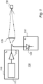
- FIG. 1 there is shown a schematic block diagram of a prior art optical system 100 for electronic distance measuring (EDM).
- EDM electronic distance measuring
- the optical system 100 comprises a transmitter 110 and a receiver 120, also denoted by "Tx" and "Rx", respectively.
- the transmitter 110 includes a 'seed' laser 111 that is constituted by a semiconductor laser, for example in distributed feedback (DFB) configuration, that generates laser pulses at a specified wavelength, and an erbium-doped fiber amplifier (EDFA) 112 that amplifies the laser pulses generated by the seed laser 111.
- the seed laser 111 is driven by a pulsed electrical current having a specified repetition rate.
- the seed laser 111 and the EDFA 112 are optically coupled via an optical fiber.
- the amplified laser pulses are then transmitted towards a target or object 130 via optical component 135, e.g. comprising at least one lens, etc.
- Laser pulses reflected off the target or object 130 are received by the receiver 120 which includes a photodiode 128 and possibly also further signal processing components.
- the photodiode 128 converts the laser pulses to received
- a distance between the optical system 100 and the target or object 130 can subsequently be determined.
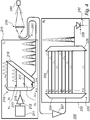
- FIG. 2 there is shown a schematic block diagram of an optical system 200 for EDM according to an embodiment of the present invention.
- the optical system 200 comprises a transmitter 210 and a receiver 220, also denoted by "Tx” and "Rx”, respectively.
- the transmitter 210 comprises a laser pulse generator 211 constituted by a wavelength tunable laser source (TLS).
- TLS 211 is adapted to generate a series of laser pulses such that the laser pulses are delayed with respect to each other and such that each laser pulse has a wavelength different from the wavelengths of other laser pulses of the series of laser pulses.
- the TLS 211 may for example comprise a semiconductor laser designed in a distributed Bragg reflector (DBR) configuration.
- the operating wavelength of the TLS 211, and hence the wavelength of a laser pulse generated by the TLS 211, can be tuned to a specified value, or channel, by applying electrical currents to the Bragg grating(s) and/or phase-tuning sections of the DBR laser cavity. Since the wavelength of the TLS 211 can be tuned electrically, and not e.g. thermally, the wavelength of the TLS 211 may be adjusted or tuned within a nanosecond or less.
- DBR distributed Bragg reflector
- WDM wavelength division multiplexing
- the generation of the series of laser pulses is illustrated in the graphs in Fig. 5 .
- Also shown in the upper graph of Fig. 5 is the first laser pulse in a series of laser pulses during the subsequent period of the laser pulse train.
- the wavelength of the TLS 211 can be swept at a certain frequency or frequencies across a predefined wavelength tuning range.
- the transmitter 210 and/or laser pulse generator 211 or TLS 211 may comprise a laser driver (not shown in Fig. 2 ).
- the laser driver may be adapted to supply a driving current to the TLS 211 so as to generate series of laser pulses such as described in the foregoing.
- the laser driver may for example be based on direct current (DC) modulation or external modulation, e.g. involving optical intensity modulator.
- the transmitter 210 comprises an optical amplifier 212 constituted by an erdium-doped fiber amplifer (EDFA).
- the optical amplifier 212 may comprise a doped fiber amplifier doped with one or several rare-earth elements.
- the EDFA 212 is adapted to amplify laser pulses generated by the TLS 211 having wavelengths within a predefined wavelength band.
- the optical amplifier or EDFA 212 is optional and may be omitted.
- the TLS 211 and the EDFA 212 may for example be optically coupled by means of an optical fiber 213 or fibers or another type of waveguide or waveguides. Any coupling between components of the system 200 in Fig. 2 , as well as in Figs. 3 , 4 , 9 and 10 , e.g. between components in the transmitter 210 and/or in the receiver 220, may for example be achieved by means of an optical fiber or optical fibers.
- the transmitter 210 is adapted to transmit the generated laser pulses and/or amplified laser pulses towards a target or object 230.
- the laser pulses are transmitted via optical component 235, e.g. comprising at least one lens and/or collimation means, etc.
- the receiver 220 is adapted to receive a series of laser pulses, which have been generated by reflection and/or scattering of the laser pulses transmitted by the transmitter 210 from the target or object 230, respectively.
- the receiver 220 comprises an optical delay module 223 adapted to delay laser pulses based on the wavelength of the respective laser pulses such that the magnitudes of delays of laser pulses having different wavelengths are different.
- the optical delay module 223 is arranged such that the magnitudes of delays corresponding to different wavelengths are such that the laser pulses that are output from the first optical delay module 223 overlap each other.
- the optical delay module 223 comprises a wavelength demultiplexer (DEMUX) 224, a plurality of waveguides 225, and a wavelength multiplexer (MUX) 226.
- DEMUX wavelength demultiplexer
- MUX wavelength multiplexer
- the waveguides 225 may for example comprise optical fibers.
- Each waveguide 225 of the plurality of waveguides 225 corresponds to one of the wavelengths of the received series of laser pulses, and each waveguide 225 of the plurality of waveguides 225 has a predefined length and is coupled to the wavelength MUX 226.
- the wavelength DEMUX 224 is arranged so as to demultiplex the received series of laser pulses onto the plurality of waveguides 225, as indicated in Fig. 2 by the respective waveforms of laser pulses on the waveguides 225, and wherein the magnitudes of the lengths of the respective waveguides 225 are such that the laser pulses that are coupled into the wavelength MUX 226 are coupled out from the wavelength MUX 226 at the same time such that the laser pulses that are output from the optical delay module 223 overlap each other, as indicated in Fig. 2 at the output of wavelength MUX 226.
- the wavelength DEMUX 224 may be based on an array waveguide grating (AWG).
- ABG array waveguide grating
- the wavelength DEMUX 224 includes one input port and N output optical fiber ports, where N is the number of wavelength channels that are used during one period T 0 of the series of laser pulses or laser pulse train.
- N is the number of wavelength channels that are used during one period T 0 of the series of laser pulses or laser pulse train.
- each laser pulse of the N laser pulses will end up in a separate optical fiber port.
- the time position of the laser pulse in each output optical fiber port is related to its wavelength channel, i.e. to the wavelength of the respective laser pulse. For example, as illustrated in Fig.
- the laser pulse in the third output optical fiber port will be delayed with respect to the laser pulse in the first output optical fiber port by a distance 2 ⁇ L , and so on.
- ⁇ may for example be about 0.4 nm or be a wavelength value included in the range 0.05-0.8 nm.
- the wavelengths ⁇ 1 , ⁇ 2 , ⁇ 3 , ..., ⁇ N may for example be wavelengths in an interval including 1.55 ⁇ m, and possibly be 'centered' on or distributed about 1.55 ⁇ m or another wavelength value in the range 1.5 ⁇ m-2 ⁇ m, e.g. for eye safety reasons.
- the optical system 200 comprises an optical amplifier 227 adapted to amplify the received series of laser pulses prior to them being input to the optical delay module 223.
- the optical amplifier 227 may for example comprise a doped fiber amplifier doped with one or more rare-earth elements, such as an EDFA.
- the optical amplifier 227 may be arranged in the receiver 220.
- the optical amplifier 227 is optional and may be omitted.
- the optical delay module 223 and the optical amplifier 227 may for example be optically coupled by means of an optical fiber or fibers or another type of waveguide or waveguides.
- the receiver 220 comprises a photosensor unit 228, e.g. one or more photodiodes such as depicted in Fig. 2 and/or a charge-coupled device (CCD), adapted to receive the overlapped laser pulses that are output from the optical delay module 223 and convert these laser pulses to a received signal, e.g. for subsequent processing for determining a distance between the optical system 200 and the target or object 230.
- a photosensor unit 228 e.g. one or more photodiodes such as depicted in Fig. 2 and/or a charge-coupled device (CCD)
- CCD charge-coupled device
- the optical system 200 comprises a time measuring module adapted to measure the elapsed time from when the laser pulses are transmitted by the transmitter 210 to detection of the laser pulses in the receiver 220.
- the time measuring module comprises a first clock line 241 adapted to sense when the laser pulses are transmitted by the transmitter 210, and a second clock line 242 adapted to sense when the overlapping laser pulses output from the optical delay module 223 have been received by the photosensor unit 228. Based on the elapsed time, a distance between the optical system 200 and the target or object 230 may be determined.
- FIG. 3 there is shown a schematic block diagram of an optical system 200 for EDM according to another embodiment of the present invention.
- the optical system 200 comprises a transmitter 210 and a receiver 220, also denoted by "Tx” and "Rx”, respectively.
- the transmitter 210 comprises a laser pulse generator 211 and an optical amplifier 212.
- the laser pulse generator 211 and the optical amplifier 212 may for example be optically coupled by means of an optical fiber or fibers or another type of waveguide or waveguides.
- the laser pulse generator 211 and the optical amplifier 212 may be similar to or the same as laser pulse generator 211 and optical amplifier 212, respectively, described with reference to Fig. 2
- the function of laser pulse generator 211 and optical amplifier 212 may be similar to or the same as the function of laser pulse generator 211 and optical amplifier 212, respectively, described with reference to Fig. 2 .
- the transmitter 210 comprises an optical delay module 215 adapted to delay laser pulses generated by laser pulse generator 211 and/or amplified laser pulses based on the wavelength of the respective laser pulses such that the magnitudes of delays of laser pulses having different wavelengths are different.
- the optical delay module 215 is arranged such that the magnitudes of delays corresponding to different wavelengths are such that the laser pulses that are output from the optical delay module 215 overlap each other.
- the optical delay module 215 comprises a wavelength DEMUX 216, a plurality of waveguides 217, and a wavelength MUX 218.
- Each waveguide 217 of the plurality of waveguides 217 corresponds to one of the wavelengths of the laser pulses.
- Each of the plurality of waveguides 217 has a predefined length, and is coupled to the wavelength MUX 218.
- the waveguides 217 may for example comprise optical fibers.
- the wavelength DEMUX 216 is arranged so as to demultiplex the laser pulses onto the plurality of waveguides 217, as indicated in Fig. 3 by the respective waveforms of laser pulses on the waveguides 217, and wherein the magnitudes of the lengths of the respective waveguides 217 are such that the laser pulses that are coupled into the wavelength MUX 218 are coupled out from the wavelength MUX 218 at the same time such that the laser pulses that are output from the optical delay module 215 overlap each other, as indicated in Fig. 3 at the output of wavelength MUX 218.
- the optical amplifier 212 is optional and may be omitted. Laser pulses generated by the laser pulse generator 211 may be directly coupled into the optical delay module 215.
- the transmitter 210 is adapted to transmit the laser pulses towards a target or object 230.
- the laser pulses are transmitted towards the target or object 230 via optical component 235, e.g. comprising at least one lens and/or collimation means, etc.
- the peak power of the laser pulse transmitted towards the target or object 230 may be increased.
- the overlapping of the laser pulses having different wavelengths may result in N times increased peak power of the laser pulse transmitted towards the target.
- the receiver 220 is adapted to receive a series of laser pulses, which have been generated by reflection and/or scattering of the laser pulses transmitted by the transmitter 210 from the target or object 230, respectively.
- the optical system 200 comprises an optical amplifier 227 such as described with reference to Fig. 2 .
- the optical amplifier 227 is optional and may be omitted.
- the receiver 220 comprises a photosensor unit 228 such as described with reference to Fig. 2 .
- the optical system 200 comprises a first clock line 241 and a second clock line 242 such as described with reference to Fig. 2 .
- FIG. 4 there is shown a schematic block diagram of an optical system 200 for EDM according to an embodiment of the present invention.
- the optical system 200 comprises a transmitter 210 and a receiver 220, also denoted by "Tx” and "Rx”, respectively.
- the transmitter 210 comprises a laser pulse generator 211 and an optical amplifier 212.
- the laser pulse generator 211 and the optical amplifier 212 may for example be optically coupled by means of an optical fiber or fibers or another type of waveguide or waveguides.
- the laser pulse generator 211 and the optical amplifier 212 may be similar to or the same as laser pulse generator 211 and optical amplifier 212, respectively, described with reference to Fig. 2
- the function of laser pulse generator 211 and optical amplifier 212 may be similar to or the same as the function of laser pulse generator 211 and optical amplifier 212, respectively, described with reference to Fig. 2 .
- the optical amplifier 212 is optional and may be omitted.
- the transmitter 210 comprises an optical delay module 215 adapted to delay laser pulses generated by laser pulse generator 211 and/or amplified laser pulses based on the wavelength of the respective laser pulses such that the magnitudes of delays corresponding to different sub-series of laser pulses having wavelengths within different wavelength sub-bands are different.
- the optical delay module 215 is arranged such that the magnitudes of delays corresponding to different sub-series of laser pulses having wavelengths within different wavelength sub-bands are such that the laser pulses are output from the optical delay module 215 such that the sub-series of laser pulses having wavelengths in different wavelength sub-bands overlap each other.
- the transmitter 210 is adapted to transmit the laser pulses towards a target or object 230.
- the laser pulses are transmitted towards the target or object 230 via optical component 235, e.g. comprising at least one lens and/or collimation means, etc.
- the receiver 220 is adapted to receive a series of laser pulses having been generated by reflection and/or scattering of the laser pulses transmitted by the transmitter 210 from the target or object 230, respectively.
- the optical system 200 comprises an optical amplifier 227 adapted to amplify the received series of laser pulses prior to them being input to the optical delay module 223.
- the optical amplifier 227 may for example comprise a doped fiber amplifier doped with one or more rare-earth elements, such as an EDFA.
- the optical amplifier 227 may be arranged in the receiver 220.
- the optical amplifier 227 is optional and may be omitted.
- the optical delay module 223 and the optical amplifier 227 may for example be optically coupled by means of an optical fiber or fibers or another type of waveguide or waveguides.
- the receiver 220 comprises a photosensor unit 228 such as described with reference to Fig. 2 .
- the receiver 220 comprises an optical delay module 223 adapted to delay laser pulses based on the wavelength of the respective laser pulses such that the magnitudes of delays of laser pulses having different wavelengths are different.
- the optical delay module 223 is arranged such that the magnitudes of delays corresponding to different wavelengths are such that the laser pulses that are output from the optical delay module 223 overlap each other.
- spectral combination of laser pulses can be employed in both the transmitter 210 and the receiver 220 of the optical system 200.
- CWDM wavelength DEMUX and MUX devices are used in the transmitter 210 for a first stage of spectral combination of laser pulses.
- a second stage of the spectral combination of laser pulses is performed in the receiver 220 using DWDM wavelength DEMUX and MUX devices.
- these values of N and M are merely according to an example - the present invention encompasses in principle any integer number of N and M with M being less than N.
- the optical delay module 215 in the transmitter 210 comprises a wavelength DEMUX 216 and a plurality of waveguides 217. Only one waveguide 217 is indicated by reference numeral in Fig. 4 . Each of the plurality of waveguides 217 corresponds to one of the wavelength sub-bands. Each of the plurality of waveguides 217 has a predefined length.
- the optical delay module 215 comprises a wavelength MUX 218, wherein each of the plurality of waveguides 217 is coupled to the wavelength MUX 218.
- the waveguides 217 may for example comprise optical fibers.
- the wavelength DEMUX 216 is arranged so as to demultiplex the received series of laser pulses onto the plurality of waveguides 217 and wherein the magnitudes of the lengths of the respective waveguides 217 are such that the sub-series of laser pulses that are coupled into the wavelength MUX 218 are coupled out from the wavelength MUX 218 at the same time such that the sub-series of laser pulses that are output from the optical delay module 215 overlap each other.
- the optical delay module 223 in the receiver 220 comprises a wavelength DEMUX 224, a plurality of waveguides 225, and a wavelength MUX 226.
- the waveguides 225 may for example comprise optical fibers. Only one of the waveguides 225 is indicated by reference numeral in Fig. 4 .
- Each waveguide 225 of the plurality of waveguides 225 corresponds to one of the wavelengths of the received series of laser pulses, and each waveguide 225 of the plurality of waveguides 225 has a predefined length and is coupled to the wavelength MUX 226.
- the wavelength DEMUX 224 is arranged so as to demultiplex the received overlapped sub-series of laser pulses onto the plurality of waveguides 225 and wherein the magnitudes of the lengths of the respective waveguides 225 are such that the laser pulses that are coupled into the wavelength MUX 226 are coupled out from the wavelength MUX 226 at the same time such that the laser pulses that are output from the optical delay module 223 overlap each other.
- the optical system 200 comprises a first clock line 241 and a second clock line 242 such as described with reference to Fig. 2 .
- FIG. 6 there is shown a schematic flow diagram of a method 600 of transmitting and receiving laser pulses according to an embodiment of the present invention.
- the method 600 comprises generating a series of laser pulses such that the laser pulses are delayed with respect to each other and such that each laser pulse has a wavelength different from the wavelengths of other laser pulses of the series of laser pulses, 601.
- generated laser pulses having wavelengths within a predefined wavelength band are amplified, 602.
- the laser pulses are transmitted towards a target or object, 603.
- Laser pulses are delayed, 605, based on the wavelength of the respective laser pulses, wherein the magnitudes of delays of laser pulses having different wavelengths are different, and the magnitudes of delays corresponding to different wavelengths are such so as to cause overlapping of the laser pulses with respect to each other.
- the method 600 may comprise delaying generated laser pulses and/or amplified laser pulses based on the wavelength of the respective laser pulses, 606, such that the magnitudes of delays corresponding to different sub-series of laser pulses having wavelengths within different wavelength sub-bands are different, and wherein the magnitudes of delays corresponding to different sub-series of laser pulses having wavelengths within different wavelength sub-bands are such so as to the sub-series of laser pulses having wavelengths in different wavelength sub-bands overlap each other.
- FIG. 7 there is shown a schematic flow diagram of a method 600 of transmitting and receiving laser pulses according to an embodiment of the present invention.
- the method 600 comprises generating a series of laser pulses such that the laser pulses are delayed with respect to each other and such that each laser pulse has a wavelength different from the wavelengths of other laser pulses of the series of laser pulses, 601.
- generated laser pulses having wavelengths within a predefined wavelength band are amplified, 602.
- Laser pulses are delayed, 607, based on the wavelength of the respective laser pulses, wherein the magnitudes of delays of laser pulses having different wavelengths are different, and the magnitudes of delays corresponding to different wavelengths are such so as to cause overlapping of the laser pulses with respect to each other.
- the laser pulses are transmitted towards a target or object, 603.
- FIG. 8 there is shown a schematic view of a computer-readable means, or computer-readable storage medium, 800 according to an embodiment of the present invention.
- the computer-readable storage medium 800 comprises a floppy disk.
- the optical system may comprise a processing unit for controlling operation of at least one of the transmitter and the receiver of the optical system.
- On the computer-readable storage medium 800 there is stored a computer program code which is configured to, when executed in a processing unit of an optical system according to an embodiment of the present invention, control operation of the transmitter and the receiver of the optical system.
- the computer program code is configured to, when executed in the processing unit of the optical system: cause the transmitter to generate a series of laser pulses such that the laser pulses are delayed with respect to each other, and such at least some of the laser pulses have a wavelength different from the wavelengths of other laser pulses of the series of laser pulses; cause the transmitter to transmit the laser pulses towards a target or object; cause the receiver to receive a series of laser pulses having been generated by reflection and/or scattering of the laser pulses from the target or object, respectively; and cause the first optical delay module in the receiver to delay laser pulses that have been received based on the wavelength of the respective laser pulses, wherein the magnitudes of delays of laser pulses having different wavelengths are different, and the magnitudes of delays corresponding to different wavelengths are such that at least some of the laser pulses that are output from the first optical delay module overlap each other.
- the computer program code is configured to, when executed in the processing unit of the optical system: cause the transmitter to generate a series of laser pulses such that the laser pulses are delayed with respect to each other and such that at least some of the laser pulses have a wavelength different from the wavelengths of other laser pulses of the series of laser pulses; cause the optical delay module to delay laser pulses based on the wavelength of the respective laser pulses, wherein the magnitudes of delays of laser pulses having different wavelengths are different, and the magnitudes of delays corresponding to different wavelengths are such that at least some of the laser pulses that are output from the optical delay module overlap each other; cause the transmitter to transmit the laser pulses towards a target or object; and cause the receiver to receive a series of laser pulses having been generated by reflection and/or scattering of the laser pulses from the target or object, respectively.
- computer-readable storage medium 800 Although only one type of computer-readable storage medium 800 has been described above with reference to Fig. 8 , the present invention encompasses embodiments employing any other suitable type of computer-readable storage medium, such as, but not limited to, a non-volatile memory, a hard disk drive, a Compact Disc (CD), a Digital Versatile Disc (DVD), a flash memory, magnetic tape, a USB stick, a Zip drive, etc.
- a non-volatile memory such as, but not limited to, a non-volatile memory, a hard disk drive, a Compact Disc (CD), a Digital Versatile Disc (DVD), a flash memory, magnetic tape, a USB stick, a Zip drive, etc.
- the distance measuring device 900 comprises an optical system 200 according to an embodiment of the present invention, e.g. an optical system 200 such as has been described in the foregoing with reference to any one of Figs. 2-4 .
- FIG. 10 there is shown a schematic block diagram of a laser pulse generator 211 in accordance with an embodiment of the present invention.
- the laser pulse generator 211 comprises a plurality of lasers 251.
- Each of the lasers 251 may for example comprise a distributed feedback (DFB) laser.
- Each laser 251 is adapted to generate laser pulses having different wavelengths with respect to laser pulses generated by the other lasers 251.
- DFB distributed feedback
- the laser pulse generator 211 further comprises a combiner 252 adapted to combine the laser pulses generated by the plurality of lasers into an optical output beam and/or a waveguide (not shown in Fig. 10 ) for outputting the generated laser pulses from the laser pulse generator 211.
- optical systems for distance measuring and methods for transmitting laser pulses and receiving laser pulses each comprise a transmitter and a receiver.
- the optical system comprises a laser pulse generator adapted to generate a train of laser pulses, each individual laser pulse in the train of laser pulses having a wavelength that differs from the wavelength of other laser pulses in the pulse train, or from the wavelength of most other laser pulses in the pulse train.
- the pulse train is transmitted towards a target or object at which it is reflected and/or scattered.
- an optical delay module By means of an optical delay module, a received series of laser pulses having different wavelengths are spectrally combined in the receiver of the optical system, resulting in overlapping of at least some of the laser pulses output from the optical delay module.
- the received signal peak power and the signal-to-noise ratio in the receiver may be increased.
Description
- The present invention generally relates to the field of range finding, or surveying. Specifically, the present invention relates to optical systems for distance measuring and methods for generating laser pulses and receiving laser pulses suitable for use in distance measuring.
- Range finding or surveying involves the determination of unknown positions, surfaces or volumes of objects using measurements of angles and distances. The determined angles and distances from a measuring instrument to points under survey may be used to calculate the coordinates of surveyed points relatively to the measuring instrument. In order to make these measurements, the measuring instrument may include an electronic distance measuring (EDM) device.
- Generally in EDM, a light beam is emitted as a light pulse towards a target or object, and light reflected by the target is subsequently detected at the measuring instrument, e.g. comprising an optical surveying instrument such as a total station. Processing of the detected signal may enable determination of distance to the target by means of, e.g., time-of-flight (TOF) or phase modulation techniques. Using the TOF technique, the TOF of a light pulse that travels from the measuring instrument, i.e. the EDM device, to a target or object, is reflected at the target or object, and returns to the measuring instrument, is determined. On the basis of the determined TOF of the light pulse, the distance between the measuring instrument and the target or object may then be calculated.
- The power loss of the received signal may determine the maximum possible operating range for which EDM can be performed. In order to increase the operating range, the power of the light beam that is transmitted towards the target or object must be increased, or be made as large as possible in order to maximize the operating range.
- In many application scenarios, the light beam is emitted as a periodic train of short laser pulses with a relatively low repetition rate. Using short pulses with a predefined pulse shape is required for achieving a high distance resolution characteristics, i.e. reduced error in the value of measured distance. Utilizing pulse trains with low repetiton rate helps to avoid ambiguity in the measurements of long distances as well as to maintain the average power of the light beam at a moderate level. In most of application scenarios, the average power of the light beam should not exceed about 10 mW for eye safety reasons.
- Therefore, the transmitter part of the EDM device must be designed for generation of a pulse train with a relatively low repetition rate and high peak power in order to maximize the operating range.
- Also for reasons of eye safety, the light beam that is transmitted towards the target preferably has a wavelength within the range 1.5 µm-2 µm or a wavelength exceeding 2 µm. In particular, the light beam that is transmitted towards the target may be preferred to have a wavelength of 1.55 µm since this may allow utilizing a variety of relatively inexpensive optical components in the EDM device such as have been developed in the telecommunication industry for applications in optical fiber communication systems and networks.
- For example, an EDM device based on TOF technique may be based on a master oscillator power amplifier (MOPA) configuration in the transmitter part of the EDM device. The transmitter part of such an EDM device typically consists of a 'seed' laser, which for example may be constituted by a semiconductor distributed feedback laser, and an erbium-doped fiber amplifier (EDFA), comprising two or more optically isolated amplification stages. The seed laser is driven by a pulsed electrical current having a certain repetition rate. The seed laser is typically capable of producing laser pulses having an optical peak power of a few tens of mW. The laser pulses that are generated in the seed laser are then amplified in the EDFA so as to achieve a certain optical peak power. The EDFA is operated in the limited range of optical pumping power, and therefore limited optical gain, such that the shape of the laser pulses amplified by the EDFA and being output from the EDFA is well preserved and free of any drastical distortions. For example, optical peak power up to 1-1.5 kW for a 'standard' erbium-doped fiber being utilized in the EDFA may be achieved. Operating the EDFA at higher pumping power, which results in increased optical gain, and aiming at achieving the optical peak power of the laser pulses that exceeds 1-1.5 kW may lead to degradation of the EDM device performance. The degradation is caused by fiber non-linearity, i.e. dependency of the refractive index of the fiber on the optical field intensity of the laser pulses propagating in the fiber. Non-linear pulse propagation in the fiber may cause an instability process that leads to pulse shape distortions such as pulse fragmentation into several sub-pulses and strong spectral broadening of the laser pulses output from the EDFA, which laser pulses are transmitted towards the target or object, the distance to which is to be measured.
- Hence, fiber non-linearity may distort the pulse shape and therefore limit the maximum achievable peak power of the laser pulses used in EDM based on TOF technique, which in turn may possibly restrict the extent of the operating range of the EDM device. To eliminate or alleviate this problem, a custom made large·mode·area fiber may possibly be utilized in the amplification stage or stages in order to reduce the intensity of the optical field in the fiber core. However, such a type of fiber may be expensive, or may be difficult to fusion splice to a standard optical fiber - if possible at all to fusion splice to a standard optical fiber, or may entail relatively high bending losses, etc.
- Fiber non-linearity may restrict the signal-to-noise ratio achievable in the receiver part of the EDM device.
-
EP1813964A2 discloses a LADAR system which includes a detector optical arrangement defining a current optical field of view.EP1813964A2 further discloses an illumination subsystem without moving parts which transmits pulsed illumination at different times to each of a number of illumination sub-regions af the current optical field of view, and a detection subsystem, including one or more detectors, detecting reflected illumination from a corresponding one or more detection sub-region of the current optical field of view.EP1813964A2 discloses that each of the detection sub-regions overlaps illumination sub-regions so that an overlap of each of the illumination sub-regions with the detection sub-region defines a LADAR image pixel of resolution finer than the detection sub-region. -
US3991318A discloses an organ array comprising a plurality of optical fibers each cut to a different length with the differences between functionally adjacent (i.e., lengthwise consecutive) fibers being uniform.US3991318A discloses that the fibers are arranged in a bundle so that one set of ends of the fibers is terminated in an input plane and the opposite set of ends is terminated in an output plane.US3991318A discloses embodiments utilizing the organ array including a passive spatial scanner, optical memory systems, an image converter, an optical sampling oscilloscope, and an x-y coordinate locater. -
US7199924B1 discloses an apparatus and a method for spectral-beam combining light from a plurality of high-power fiber lasers that use two substantially identical diffraction gratings in a parallel, mutually compensating configuration to combine a plurality of separate parallel input beams each having a slightly different successively higher wavelength into a single output beam of high quality.US7199924B1 further discloses a single diffraction grating used to combine a plurality of different wavelengths, wherein the input laser beams are obtained from very narrow linewidth sources to reduce chromatic dispersion.US7199924B1 discloses that diagnostics and adjustments of wavelengths and/or positions and angles are made dynamically in real time to maintain the combination of the plurality input beams into a single high-quality output beam. -
WO2011/000411A1 discloses a method for driving a laser diode such as to enable mitigation or elimination of so called spiking effects related to the number of injected carriers in the laser overshooting the equilibrium value at the beginning of the lasing process.WO2011/000411A1 discloses that in this manner, the efficiency of a master oscillator power amplifier that may be utilized in range finding applications will be improved. -
US2008074640A1 discloses methods for using spectrally separated light pulses to collect more LIDAR information are presented.US2008074640A1 discloses that a monochromatic pulse is transmitted to collect range information and a white pulse is transmitted a short time afterwards to collect spectral responsivity information or color of the target.US2008074640A1 discloses that the white light pulse is used to collect both range and spectral responsivity information of the target.US2008074640A1 discloses that the spectral separated laser is spatially spread in order to collect range information over more than one point at a time. - In view of the above discussion, a concern of the present invention is to provide an optical system for distance measuring that alleviates or even eliminates restrictions of the operating range for EDM related to fiber non-linearity.
- Another concern of the present invention is to provide an optical system for distance measuring that alleviates or even eliminates restrictions on signal-to-noise ratio achievable in the receiver part of the optical system related to fiber non-linearity.
- Another concern of the present invention is to provide an optical system for distance measuring that alleviates or even eliminates restrictions of the operating range for EDM related to fiber non-linearity while not requiring expensive components.
- Another concern of the present invention is to provide an optical system for distance measuring that alleviates or even eliminates restrictions on signal-to-noise ratio achievable in the receiver part of the optical system related to fiber non-linearity while not requiring expensive components.
- To address one or more of these concerns and other concerns, optical systems and methods in accordance with the independents claims are provided. Preferred embodiments are defined by the dependent claims.
- A gist of the present invention is to spectrally combine a train of laser pulses that are generated at a number of different wavelengths in a measuring instrument, in particular an electronic distance measuring (EDM) device. Such spectral combination of a train of laser pulses generated at a number of different wavelengths may take place in an EDM device in the receiver part thereof, in the transmitter part thereof, or in both the transmitter part and the receiver part of the EDM device.
- As described further in the following, by such spectral combination of a train of laser pulses, the ocurrence of high peak optical power in optical fiber of an amplification stage in the EDM device may be decreased or even eliminated, while the signal-to-noise ratio at the receiver part of the optical system and the operating range of the optical system may be increased.
- According to a first aspect of the present invention, there is provided an optical system for distance measuring. The optical system comprises a transmitter and a reciver.
- The transmitter comprises a laser pulse generator adapted to generate a series of laser pulses such that the laser pulses are delayed with respect to each other, and such that each laser pulse has a wavelength different from the wavelengths of other laser pulses of the series of laser pulses, or such that at least some of the laser pulses have a wavelength different from the wavelengths of other laser pulses of the series of laser pulses.
- The transmitter may comprise an optical amplifier adapted to amplify laser pulses generated by the laser pulse generator having wavelengths within a predefined wavelength band.
- The transmitter is adapted to transmit the amplified laser pulses and/or laser pulses generated by the laser pulse generator towards a target or object.
- The receiver is adapted to receive a series of laser pulses which have been generated by reflection and/or scattering of the laser pulses transmitted by the transmitter from the target or object, respectively.
- The receiver comprises a first optical delay module adapted to delay laser pulses based on the wavelength of the respective laser pulses such that the magnitudes of delays of laser pulses having different wavelengths are different. The first optical delay module is arranged such that the magnitudes of delays corresponding to different wavelengths are such that the laser pulses that are output from the first optical delay module, or at least some of the laser pulses that are output from the first optical delay module, overlap or substantially overlap each other.
- In other words, the laser pulse generator may be adapted to generate a periodic train of laser pulses such that a series (finite number) of pulses is generated during each period of the pulse train, each individual laser pulse in the seriesof laser pulses having a wavelength that differs from the wavelength of other laser pulses in the series of pulses, or from the wavelength of most of the other laser pulses in the series of pulses. Each laser pulse in the pulse train may have a predefined pulse width. Successive laser pulses in a period of the pulse train may be delayed with respect to each other by one or a few laser pulse widths so as to mitigate or avoid laser pulse shape distortions.
- By means of the first optical delay module, the received series of laser pulses having different wavelengths can be spectrally combined in the receiver of the optical system.
- By amplification of laser pulses generated by the laser pulse generator that are delayed in respect to each other, nonlinear effects and nonlinear pulse distortions may be mitigated or even eliminated.
- By the spectral combination of the received series of laser pulses achieved by means of the first optical delay module, resulting in overlapping of laser pulses output from the first optical delay module, the received signal peak power and the signal-to-noise ratio in the receiver may be increased. According to one example, for N laser pulses, each at different wavelength, in the received series of laser pulses, the overlapping of N laser pulses output from the first optical delay module may result in N times increased peak power of the received signal on basis of which TOF may be determined. Due to increased peak power of the received signal at the receiver, the operating range of the optical system may be increased, whereby the optical system may become capable of measuring larger distances between the optical system and the target or object, corresponding to higher losses of the signal during the return trip from the optical system to the object or target and back to the optical system.
- The first optical delay module may for example comprise a wavelength demultiplexer (DEMUX) and a plurality of waveguides.
- Each of the plurality of waveguides may correspond to one of the wavelengths of the received series of laser pulses.
- Each of the plurality of waveguides may have a predefined length.
- The wavelength DEMUX may be arranged so as to demultiplex the received series of laser pulses onto the plurality of waveguides, wherein the magnitudes of the lengths of the respective waveguides may be such that the laser pulses are coupled out from the plurality of waveguides at the same time, whereby the laser pulses that are output from the first optical delay module overlap or substantially overlap each other.
- The wavelength DEMUX may for example be based on an array waveguide grating. The plurality of waveguides may for example comprise a plurality of optical fibers.
- For example, the wavelength DEMUX may have one input port and N output optical fiber ports, where N is the number of laser pulses or wavelength channels that are used in the laser pulse train generated in the laser pulse generator of the optical system's transmitter. At the output of the wavelength DEMUX, each laser pulse of the respective N laser pulses may enter a corresponding optical fiber port. The time position of the laser pulse in each output fiber port may be related or correspond to its wavelength channel, i.e. the wavelength of the laser pulse in the output fiber port. The magnitudes of the lengths of the respective optical fibers may be such that laser pulses are coupled out from the plurality of optical fibers at the same time, whereby laser pulses that are output from the first optical delay module overlap each other.
- The overlapped laser pulses output from the first optical delay module may then be coupled into or impinge on a photosensor unit such as at least one photodiode in the optical system's receiver. Thereby, a received signal may be generated which may be further processed e.g. for performing EDM.
- The first optical delay module may comprise a wavelength multiplexer (MUX).
- Each of the plurality of waveguides may be coupled to the wavelength MUX.
- The wavelength DEMUX may be arranged so as to demultiplex the received series of laser pulses onto the plurality of waveguides, wherein the magnitudes of the lengths of the respective waveguides may be such that the laser pulses that are coupled into the wavelength MUX are coupled out from the wavelength MUX at the same time such that the laser pulses that are output from the first optical delay module overlap or substantially overlap each other.
- For example, output optical fiber ports of the wavelength DEMUX may be spliced to input optical fiber ports of the wavelength MUX. In the case where the wavelength DEMUX has one input port and N output optical fiber ports, where N is the number of laser pulses or wavelength channels that are used in the laser pulse train generated in the laser pulse generator of the optical system's transmitter, all N laser pulses may overlap in the output optical fiber port of the wavelength MUX.
- The overlapped laser pulses in the output optical fiber port of the wavelength MUX may then be coupled into or impinge on a photosensor unit such as at least one photodiode in the optical system's receiver. Thereby, a received signal may be generated which may be further processed e.g. for performing EDM.
- The receiver may comprise an optical amplifier adapted to amplify the received series of laser pulses prior to them being input to the first optical delay module. The optical amplifier may for example comprise a doped fiber amplifer (DFA).
- The transmitter may comprise a second optical delay module adapted to delay the amplified laser pulses and/or laser pulses generated by the laser pulse generator based on the wavelength of the respective laser pulses such that the magnitudes of delays corresponding to different sub-series of laser pulses having wavelengths within different wavelength sub-bands are different.
- The second optical delay module may be arranged such that the magnitudes of delays corresponding to different sub-series of laser pulses having wavelengths within different wavelength sub-bands are such that the laser pulses are output from the second optical delay module such that the sub-series of laser pulses having wavelengths in different wavelength sub-bands overlap or substantially overlap each other.
- By means of the second optical delay module, the amplified laser pulses and/or laser pulses generated by the laser pulse generator having different wavelengths can be spectrally combined in the transmitter of the optical system.
- Thereby, the peak power of the laser pulses transmitted towards the target or object may be increased. For N amplified laser pulses and/or laser pulses generated by the laser pulse generator, the overlapping of M sub-series of laser pulses having wavelengths in different wavelength sub-bands may result in M times increased peak power of the laser pulses transmitted towards the target.
- Providing an optical delay module both in the transmitter and in the receiver may facilitate manufacture of the optical system, particularly in case the laser pulse generator is adapted to generate a train of laser pulses including a relatively large number of laser pulses. This is due to that in order to delay a relatively large number of laser pulses, relatively long waveguides such as optical fibers may be required. Arranging or installing relatively long waveguides in the optical system may be difficult. However, by providing an optical delay module both in the transmitter and in the receiver, the total length of the waveguides that is required may be 'split' between the transmitter and the receiver, which may facilitate installation of the waveguides in the optical system for the implementation of the optical delay modules.
- The second optical delay module may comprise a wavelength DEMUX and a plurality of waveguides.
- Each of the plurality of waveguides may correspond to one of the wavelength sub-bands.
- Each of the plurality of waveguides may have a predefined length.
- The wavelength DEMUX may be arranged so as to demultiplex the series of laser pulses received by the second optical delay module onto the plurality of waveguides, wherein the magnitudes of the lengths of the respective waveguides may be such that the sub-series of laser pulses are coupled out from the plurality of waveguides at the same time, so that the sub-series of laser pulses having wavelengths within different wavelength sub-bands that are output from the second optical delay module overlap each other.
- The second optical delay module may comprise a wavelength MUX.
- Each of the plurality of waveguides may be coupled to the wavelength MUX.
- The wavelength DEMUX may be arranged so as to demultiplex the received series of laser pulses onto the plurality of waveguides, wherein the magnitudes of the lengths of the respective waveguides are such that the sub-series of laser pulses that are coupled into the wavelength MUX are coupled out from the wavelength MUX at the same time such that the sub-series of laser pulses that are output from the second optical delay module overlap each other.
- The first optical delay module may comprise a wavelength demultiplexer and a plurality of waveguides.
- Each of the plurality of waveguides may correspond to one of the wavelengths of the received overlapped sub-series of laser pulses.
- Each of the plurality of waveguides may have a predefined length.
- The demultiplexer may be arranged so as to demultiplex the received overlapped sub-series of laser pulses onto the plurality of waveguides, wherein the magnitudes of the lengths of the respective waveguides are such that the laser pulses are coupled out from the plurality of waveguides at the same time, whereby the laser pulses that are output from the first optical delay module overlap or substantially overlap each other.
- The first optical delay module may comprise a wavelength multiplexer.
- Each of the plurality of waveguides may be coupled to the wavelength multiplexer.
- The demultiplexer may be arranged so as to demultiplex the received overlapped sub-series of laser pulses onto the plurality of waveguides, wherein the magnitudes of the lengths of the respective waveguides are such that the laser pulses that are coupled into the wavelength multiplexer are coupled out from the wavelength multiplexer at the same time such that the laser pulses that are output from the first optical delay module overlap or substantially overlap each other.
- The receiver may comprise an optical amplifier adapted to amplify the received overlapped sub-series of laser pulses prior to them being input to the first optical delay module.
- According to a second aspect of the present invention, there is provided an optical system for distance measuring. The optical system comprises a transmitter and a receiver.
- The transmitter comprises a laser pulse generator adapted to generate a series of laser pulses such that the laser pulses are delayed with respect to each other, and such that each laser pulse has a wavelength different from the wavelengths of other laser pulses of the series of laser pulses, or such that at least some of the laser pulses have a wavelength different from the wavelengths of other laser pulses of the series of laser pulses.
- The transmitter may comprise an optical amplifier adapted to amplify laser pulses generated by the laser pulse generator having wavelengths within a predefined wavelength band.
- The transmitter comprises an optical delay module adapted to delay the amplified laser pulses and/or laser pulses generated by the laser pulse generator based on the wavelength of the respective laser pulses such that the magnitudes of delays of laser pulses having different wavelengths are different. The optical delay module is arranged such that the magnitudes of delays corresponding to different wavelengths are such that the laser pulses that are output from the optical delay module, or at least some of the laser pulses that are output from the first optical delay module, overlap each other.
- The transmitter is adapted to transmit the laser pulses towards a target or object.
- The receiver is adapted to receive a laser pulses having been generated by reflection and/or scattering of the laser pulses transmitted by the transmitter from the target or object, respectively.
- By means of the optical delay module in the transmitter, the amplified laser pulses and/or laser pulses generated by the laser pulse generator having different wavelengths can be spectrally combined in the transmitter of the optical system.
- By amplification of laser pulses generated by the laser pulse generator that are delayed in respect to each other, nonlinear effects and nonlinear pulse distortions may be mitigated or even eliminated.
- By the spectral combination of the amplified laser pulses and/or laser pulses generated by the laser pulse generator, resulting in overlapping of the laser pulses output from the optical delay module in the transmitter, the received signal peak power and the signal-to-noise ratio in the receiver may be increased.
- Thereby, the peak power of the laser pulse transmitted towards the target or object may be increased. For example for N amplified laser pulses and/or laser pulses generated by the laser pulse generator, the overlapping of the laser pulses having different wavelengths may result in N times increased peak power of the laser pulse transmitted towards the target or object.
- Thereby, increased peak power of the received signal at the receiver may be achieved, possibly allowing the operating range of the optical system to be increased, whereby the optical system may become capable of measuring larger distances between the optical system and the target or object, corresponding to higher losses of the signal during the return trip from the optical system to the object or target and back to the optical system.
- Hence, the optical systems according to the first and second aspects of the present invention, respectively, may provide alternative solutions to the same problem of how to alleviate or eliminate restrictions of the operating range for EDM related to fiber non-linearity and/or how to alleviate or eliminate restrictions on signal-to-noise ratio achievable in the receiver part of the optical system related to fiber non-linearity.
- The optical delay module may comprise a wavelength demultiplexer and a plurality of waveguides.
- Each of the plurality of waveguides may correspond to one of the wavelengths of the received series of laser pulses.
- Each of the plurality of waveguides may have a predefined length.
- The demultiplexer may be arranged so as to demultiplex the received series of laser pulses onto the plurality of waveguides, wherein the magnitudes of the lengths of the respective waveguides are such that the laser pulses are coupled out from the plurality of waveguides at the same time, whereby the laser pulses that are output from the optical delay module overlap or substantially overlap each other.
- The optical delay module may comprise a wavelength multiplexer.
- Each of the plurality of waveguides may be coupled to the wavelength multiplexer.
- The demultiplexer may be arranged so as to demultiplex the received series of laser pulses onto the plurality of waveguides, wherein the magnitudes of the lengths of the respective waveguides are such that the laser pulses that are coupled into the wavelength multiplexer are coupled out from the wavelength multiplexer at the same time such that the laser pulses that are output from the optical delay module overlap or substantially overlap each other.
- The receiver may comprise an optical amplifier adapted to amplify the received laser pulses.
- The laser pulse generator may for example comprise a wavelength tunable laser or wavelength tunable laser source (TLS).
- By means of a TLS, a series of laser pulses being delayed with respect to each other, at least some of the laser pulses having respective wavelengths different from the wavelengths of other laser pulses of the series of laser pulses, can be generated.
- The TLS may for example comprise a semiconductor laser that is designed in a distributed Bragg reflector (DBR) configuration. The operating wavelength of the TLS, and hence the wavelength of a laser pulse generated by the TLS, can be tuned to a specified value, or channel, by applying electrical currents to the Bragg grating and phase-tuning sections of the DBR laser cavity while maintaining the operation in single-mode regime. Since the wavelength of the TLS is tuned electrically, and not e.g. thermally, the wavelength of the TLS may be adjusted or tuned within a nanosecond or less.
- The TLS may be operated in such a way that a specified number N of laser pulses, each laser pulse having a specified wavelength λi , i=1, 2, ..., N, are generated during each period of the laser pulse train.
- The wavelengths λi , i=1, 2, ..., N, may for example be the wavelength values in a standard wavelength division multiplexing (WDM) ITU grid.
- Alternatively or optionally, the laser pulse generator may comprise a plurality of lasers, e.g. distributed feedback (DFB) lasers, wherein each laser of the plurality of lasers is adapted to generate laser pulses having different wavelengths with respect to laser pulses generated by the other lasers. The laser pulse generator may comprise a combiner adapted to combine the laser pulses generated by the plurality of lasers into an optical output beam and/or a waveguide.
- According to another example, the laser pulse generator may comprise a plurality of lasers, e.g. DFB lasers, where each laser is adapted to generate laser pulses having different wavelengths with respect to laser pulses generated by the other lasers, and a wavelength tunable laser or TLS. The wavelength tunable laser or TLS is hence separate from the plurality of lasers. The laser pulse generator may comprise a combiner adapted to combine the laser pulses generated by the plurality of lasers, and possibly also laser pulses generated by the wavelength tunable laser or TLS, into an optical output beam and/or a waveguide.
- In the foregoing and in the following, optical delay modules have been and are described having a functionality so as to be capable of producing an overlapping of the laser pulses being output from the respective optical delay modules. However, the present invention encompasses where the laser pulses being output from the respective optical delay modules are substantially overlapping each other and/or where most of the laser pulses being output from the respective optical delay modules overlap each other, e.g. where a predetermined fraction of the laser pulses being output from the respective optical delay modules overlap each other. The predetermined fraction may for example be 90% or more, or 95% or more, of the laser pulses being output from the respective optical delay modules overlap each other.
- The laser pulses output from the respective optical delay modules which are overlapping each other may be detected. To this end, the optical system may comprise an optical signal detecting module, e.g. including a photosensor unit, adapted to detect the laser pulses being output from the respective optical delay modules overlapping each other.
- The elapsed time from when the laser pulses are transmitted towards the target or object to when the laser pulses output from the respective optical delay modules which are overlapping each other are detected may be measured. To this end, the optical system may comprise a time measuring module adapted to measure the elapsed time from when the laser pulses are transmitted by the transmitter to when the laser pulses output from the respective optical delay modules which are overlapping each other are detected by the optical signal detecting module.
- Based on the elapsed time, the distance between the target or object and the optical system may be determined, e.g. by means of a processing unit.
- According to a third aspect of the present invention, there is provided a method for transmitting laser pulses and receiving laser pulses.
- The method comprises generating a series of laser pulses such that the laser pulses are delayed with respect to each other, and such that each laser pulse has a wavelength different from the wavelengths of other laser pulses of the series of laser pulses, or such that at least some of the laser pulses have a wavelength different from the wavelengths of other laser pulses of the series of laser pulses.
- Generated laser pulses having wavelengths within a predefined wavelength band may be amplified.
- The laser pulses are transmitted towards a target or object.
- A series of laser pulses having been generated by reflection and/or scattering of the laser pulses from the target or object, respectively, is received.
- Laser pulses that have been received are delayed based on the wavelength of the respective laser pulses, wherein the magnitudes of delays of laser pulses having different wavelengths are different, and the magnitudes of delays corresponding to different wavelengths are such so as to cause overlapping or near overlapping of the laser pulses or at least some of the laser pulses with respect to each other.
- Amplified laser pulses and/or generated laser pulses in the series of laser pulses may be delayed based on the wavelength of the respective laser pulses, such that the magnitudes of delays corresponding to different sub-series of laser pulses having wavelengths within different wavelength sub-bands are different, wherein the magnitudes of delays corresponding to different sub-series of laser pulses having wavelengths within different wavelength sub-bands are such so as to cause the sub-series of laser pulses having wavelengths in different wavelength sub-bands to overlap or substantially overlap each other.
- According to a fourth aspect of the present invention, there is provided a method for transmitting laser pulses and receiving laser pulses.
- The method comprises generating a series of laser pulses such that the laser pulses are delayed with respect to each other and such that each laser pulse has a wavelength different from the wavelengths of other laser pulses of the series of laser pulses, or such that at least some of the laser pulses have a wavelength different from the wavelengths of other laser pulses of the series of laser pulses.
- Generated laser pulses having wavelengths within a predefined wavelength band may be amplified.
- Laser pulses are delayed based on the wavelength of the respective laser pulses, wherein the magnitudes of delays of laser pulses having different wavelengths are different, and the magnitudes of delays corresponding to different wavelengths are such so as to cause overlapping or near overlapping of the laser pulses or at least some of the laser pulses with respect to each other.
- The laser pulses are transmitted towards a target or object.
- A series of laser pulses having been generated by reflection and/or scattering of the laser pulses from the target or object, respectively, is received.
- According to a fifth aspect of the present invention, there is provided a computer program product adapted to, when executed in a processor unit, perform a method according to the present invention.
- According to a sixth aspect of the present invention, there is provided a computer-readable storage medium on which there is stored a computer program product adapted to, when executed in a processor unit, perform a method according to the present invention.
- According to a seventh aspect of the present invention, there is provided a distance measuring device comprising an optical system according to the present invention.
- The optical system may comprise a processing unit for controlling operation of at least one of the transmitter and the receiver of the optical system.
- According to an eight aspect of the present invention, there is provided a computer program product adapted to be executed in the processing unit of the optical system. The computer program product comprises computer-readable means carrying computer program code. The computer program code is configured to, when executed in the processing unit of the optical system, cause the transmitter to generate a series of laser pulses such that the laser pulses are delayed with respect to each other, and such that each laser pulse has a wavelength different from the wavelengths of other laser pulses of the series of laser pulses, or such that at least some of the laser pulses have a wavelength different from the wavelengths of other laser pulses of the series of laser pulses. The computer program code may be configured to, when executed in the processing unit of the optical system, cause the optical amplifier to amplify generated laser pulses having wavelengths within a predefined wavelength band. The computer program code is configured to, when executed in the processing unit of the optical system, cause the transmitter to transmit the laser pulses towards a target or object. The computer program code is configured to, when executed in the processing unit of the optical system, cause the receiver to receive a series of laser pulses having been generated by reflection and/or scattering of the laser pulses from the target or object, respectively. The computer program code is configured to, when executed in the processing unit of the optical system, cause the optical delay module in the receiver to delay laser pulses that have been received based on the wavelength of the respective laser pulses, wherein the magnitudes of delays of laser pulses having different wavelengths are different, and the magnitudes of delays corresponding to different wavelengths are such that at least some of the laser pulses that are output from the optical delay module overlap each other. The computer program code may be configured to, when executed in the processing unit of the optical system, cause amplified laser pulses and/or generated laser pulses in the series of laser pulses to be delayed based on the wavelength of the respective laser pulses, such that the magnitudes of delays corresponding to different sub-series of laser pulses having wavelengths within different wavelength sub-bands are different, wherein the magnitudes of delays corresponding to different sub-series of laser pulses having wavelengths within different wavelength sub-bands are such so as to cause the sub-series of laser pulses having wavelengths in different wavelength sub-bands to overlap or substantially overlap each other.
- According to a ninth aspect of the present invention, there is provided a computer program product adapted to be executed in the processing unit of the optical system. The computer program product comprises computer-readable means carrying computer program code. The computer program code is configured to, when executed in the processing unit of the optical system, cause the transmitter to generate a series of laser pulses such that the laser pulses are delayed with respect to each other and such that each laser pulse has a wavelength different from the wavelengths of other laser pulses of the series of laser pulses, or such that at least some of the laser pulses have a wavelength different from the wavelengths of other laser pulses of the series of laser pulses. The computer program code may be configured to, when executed in the processing unit of the optical system, cause the optical amplifier to amplify generated laser pulses having wavelengths within a predefined wavelength band. The computer program code is configured to, when executed in the processing unit of the optical system, cause the optical delay module in the transmitter to delay laser pulses based on the wavelength of the respective laser pulses, wherein the magnitudes of delays of laser pulses having different wavelengths are different, and the magnitudes of delays corresponding to different wavelengths are such that at least some of the laser pulses that are output from the optical delay module overlap each other. The computer program code is configured to, when executed in the processing unit of the optical system, cause the transmitter to transmit the laser pulses towards a target or object. The computer program code is configured to, when executed in the processing unit of the optical system, cause the receiver to receive a series of laser pulses having been generated by reflection and/or scattering of the laser pulses from the target or object, respectively.
- The processing unit may include or be constituted by any suitable central processing unit (CPU), microcontroller, digital signal processor (DSP), Application Specific Integrated Circuit (ASIC), Field Programmable Gate Array (FPGA), etc., or any combination thereof. The processing unit may optionally be capable of executing software instructions stored in a computer program product e.g. in the form of a memory. The memory may for example be any combination of read and write memory (RAM) and read only memory (ROM). The memory may comprise persistent storage, which for example can be a magnetic memory, an optical memory, a solid state memory or a remotely mounted memory, or any combination thereof.
- In the context of the present application, by an optical amplifier it is meant a device that can amplify an optical signal without the need to first convert the optical signal to an electrical signal.
- In the context of the present application, by a DFA it is meant an optical amplifier which utilizes a doped optical fiber as a gain medium to amplify an optical signal.
- For example, the doped optical fiber of the DFA may be doped with at least one rare-earth element such as Er, Yb, Nd and/or Tm.
- Further objects and advantages of the present invention are described in the following by means of exemplifying embodiments.
- It is noted that the present invention relates to all possible combinations of features recited in the claims. Further features of, and advantages with, the present invention will become apparent when studying the appended claims and the following description. Those skilled in the art realize that different features of the present invention can be combined to create embodiments other than those described in the following.
- Exemplifying embodiments of the invention will be described below with reference to the accompanying drawings, in which:
-
Fig. 1 is a schematic block diagram of a prior art optical system for electronic distance measuring (EDM); -
Figs. 2-4 are schematic block diagrams of optical systems for EDM according to embodiments of the present invention; -
Fig. 5 are graphs illustrating generation of a series of laser pulses in accordance with an embodiment of the present invention; -
Figs. 6 and7 are schematic flow diagrams of methods of transmitting and receiving laser pulses according to embodiments of the present invention; -
Fig. 8 is a schematic view of a computer-readable storage medium according to an embodiment of the present invention; -
Fig. 9 is a schematic block diagram of a distance measuring device according to an embodiment of the present invention; and -
Fig. 10 is a schematic block diagram of a laser pulse generator in accordance with an embodiment of the present invention. - The present invention will now be described hereinafter with reference to the accompanying drawings, in which exemplifying embodiments of the present invention are shown. The present invention may, however, be embodied in many different forms and should not be construed as limited to the embodiments set forth herein; rather, these embodiments are provided by way of example so that this disclosure will convey the scope of the invention to those skilled in the art. Furthermore, like numbers refer to like or similar elements or components throughout. The steps of any method disclosed herein do not have to be performed in the exact order disclosed, unless explicitly stated.
- Referring now to
Fig. 1 , there is shown a schematic block diagram of a prior artoptical system 100 for electronic distance measuring (EDM). - The
optical system 100 comprises atransmitter 110 and areceiver 120, also denoted by "Tx" and "Rx", respectively. Thetransmitter 110 includes a 'seed'laser 111 that is constituted by a semiconductor laser, for example in distributed feedback (DFB) configuration, that generates laser pulses at a specified wavelength, and an erbium-doped fiber amplifier (EDFA) 112 that amplifies the laser pulses generated by theseed laser 111. Theseed laser 111 is driven by a pulsed electrical current having a specified repetition rate. Theseed laser 111 and theEDFA 112 are optically coupled via an optical fiber. The amplified laser pulses are then transmitted towards a target or object 130 viaoptical component 135, e.g. comprising at least one lens, etc. Laser pulses reflected off the target or object 130 are received by thereceiver 120 which includes aphotodiode 128 and possibly also further signal processing components. Thephotodiode 128 converts the laser pulses to received signals. - Based on an elapsed time as determined e.g. from emission of a laser pulse from the
transmitter 110 to receipt of a received signal by the receiver's 120photodiode 128, a distance between theoptical system 100 and the target or object 130 can subsequently be determined. - Referring now to
Fig. 2 , there is shown a schematic block diagram of anoptical system 200 for EDM according to an embodiment of the present invention. - The
optical system 200 comprises atransmitter 210 and areceiver 220, also denoted by "Tx" and "Rx", respectively. - The
transmitter 210 comprises alaser pulse generator 211 constituted by a wavelength tunable laser source (TLS). TheTLS 211 is adapted to generate a series of laser pulses such that the laser pulses are delayed with respect to each other and such that each laser pulse has a wavelength different from the wavelengths of other laser pulses of the series of laser pulses. - The
TLS 211 may for example comprise a semiconductor laser designed in a distributed Bragg reflector (DBR) configuration. The operating wavelength of theTLS 211, and hence the wavelength of a laser pulse generated by theTLS 211, can be tuned to a specified value, or channel, by applying electrical currents to the Bragg grating(s) and/or phase-tuning sections of the DBR laser cavity. Since the wavelength of theTLS 211 can be tuned electrically, and not e.g. thermally, the wavelength of theTLS 211 may be adjusted or tuned within a nanosecond or less. - The
TLS 211 may be operated in such a way that a specified number N of laser pulses, each laser pulse having a specified wavelength λi , i=1, 2, ..., N, are generated during each period T 0 of the series of laser pulses or laser pulse train. The wavelengths λi , i=1, 2, ..., N, may for example be the wavelength values in a standard wavelength division multiplexing (WDM) ITU grid. - The generation of the series of laser pulses is illustrated in the graphs in
Fig. 5 . The upper graph inFig. 5 is a graph of laser pulse power P(t) as a function of time t, showing laser pulses in a series of laser pulses or laser pulse train separated in time by ΔT and having wavelengths λi , i=1, 2, ..., N, during period T 0. Both P(t) and t are given in arbitrary units. Also shown in the upper graph ofFig. 5 is the first laser pulse in a series of laser pulses during the subsequent period of the laser pulse train. The lower graph inFig. 5 is a graph of the wavelengths λ(t)=λi , i=1, 2, ..., N, during period T 0 as a function of time t. Both λ(t) and t are given in arbitrary units. As can be seen in the lower graph inFig. 5 , the wavelengths λi , i=1, 2, ..., N, monotonously increase with increasing time t during period T 0. Such a variation of the wavelengths λi , i=1, 2, ..., N, relatively to each other during period T 0 is according to an example. In principle, any sort of variation of the wavelengths λi , i=1, 2, ..., N, relatively to each other is possible, as long as all or most wavelengths λi , i=1, 2, ..., N, differ with respect to each other. - Alternatively or optionally, the wavelength of the
TLS 211 can be swept at a certain frequency or frequencies across a predefined wavelength tuning range. - The
transmitter 210 and/orlaser pulse generator 211 orTLS 211 may comprise a laser driver (not shown inFig. 2 ). The laser driver may be adapted to supply a driving current to theTLS 211 so as to generate series of laser pulses such as described in the foregoing. The laser driver may for example be based on direct current (DC) modulation or external modulation, e.g. involving optical intensity modulator. - The
transmitter 210 comprises anoptical amplifier 212 constituted by an erdium-doped fiber amplifer (EDFA). Alternatively or optionally, theoptical amplifier 212 may comprise a doped fiber amplifier doped with one or several rare-earth elements. TheEDFA 212 is adapted to amplify laser pulses generated by theTLS 211 having wavelengths within a predefined wavelength band. The optical amplifier orEDFA 212 is optional and may be omitted. - The
TLS 211 and theEDFA 212 may for example be optically coupled by means of anoptical fiber 213 or fibers or another type of waveguide or waveguides. Any coupling between components of thesystem 200 inFig. 2 , as well as inFigs. 3 ,4 ,9 and 10 , e.g. between components in thetransmitter 210 and/or in thereceiver 220, may for example be achieved by means of an optical fiber or optical fibers. - The
transmitter 210 is adapted to transmit the generated laser pulses and/or amplified laser pulses towards a target orobject 230. According to the embodiment depicted inFig. 2 , the laser pulses are transmitted viaoptical component 235, e.g. comprising at least one lens and/or collimation means, etc. - The
receiver 220 is adapted to receive a series of laser pulses, which have been generated by reflection and/or scattering of the laser pulses transmitted by thetransmitter 210 from the target orobject 230, respectively. - The
receiver 220 comprises anoptical delay module 223 adapted to delay laser pulses based on the wavelength of the respective laser pulses such that the magnitudes of delays of laser pulses having different wavelengths are different. Theoptical delay module 223 is arranged such that the magnitudes of delays corresponding to different wavelengths are such that the laser pulses that are output from the firstoptical delay module 223 overlap each other. - According to the embodiment depicted in
Fig. 2 , theoptical delay module 223 comprises a wavelength demultiplexer (DEMUX) 224, a plurality ofwaveguides 225, and a wavelength multiplexer (MUX) 226. - The
waveguides 225 may for example comprise optical fibers. - Each
waveguide 225 of the plurality ofwaveguides 225 corresponds to one of the wavelengths of the received series of laser pulses, and eachwaveguide 225 of the plurality ofwaveguides 225 has a predefined length and is coupled to thewavelength MUX 226. - The
wavelength DEMUX 224 is arranged so as to demultiplex the received series of laser pulses onto the plurality ofwaveguides 225, as indicated inFig. 2 by the respective waveforms of laser pulses on thewaveguides 225, and wherein the magnitudes of the lengths of therespective waveguides 225 are such that the laser pulses that are coupled into thewavelength MUX 226 are coupled out from thewavelength MUX 226 at the same time such that the laser pulses that are output from theoptical delay module 223 overlap each other, as indicated inFig. 2 at the output ofwavelength MUX 226. - For example, the
wavelength DEMUX 224 may be based on an array waveguide grating (AWG). - According to the example depicted in
Fig. 2 , thewavelength DEMUX 224 includes one input port and N output optical fiber ports, where N is the number of wavelength channels that are used during one period T 0 of the series of laser pulses or laser pulse train. At the output of thewavelength DEMUX 224, each laser pulse of the N laser pulses will end up in a separate optical fiber port. The time position of the laser pulse in each output optical fiber port is related to its wavelength channel, i.e. to the wavelength of the respective laser pulse. For example, as illustrated inFig. 2 , if the wavelength of the first laser pulse in the series of laser pulse is set to λ1 and the wavelength of each next pulse during the laser pulse train period is increased by Δλ up to λN for the final laser pulse in the period (Δλ being the wavelength channel spacing), the laser pulse in the second output optical fiber port (corresponding to wavelength λ2) will be delayed with respect to the laser pulse in the first output optical fiber port by a distance ΔL=vg·ΔT, where ΔT is the time delay between the laser pulses in the first and second optical fiber ports, vg is the group velocity of light in the optical fibers. The laser pulse in the third output optical fiber port will be delayed with respect to the laser pulse in the first output optical fiber port by adistance 2·ΔL, and so on. - In some applications, Δλ may for example be about 0.4 nm or be a wavelength value included in the range 0.05-0.8 nm.
- The wavelengths λ1, λ2, λ3, ..., λN, may for example be wavelengths in an interval including 1.55 µm, and possibly be 'centered' on or distributed about 1.55 µm or another wavelength value in the range 1.5 µm-2 µm, e.g. for eye safety reasons.
- According to the embodiment depicted in
Fig. 2 , theoptical system 200 comprises anoptical amplifier 227 adapted to amplify the received series of laser pulses prior to them being input to theoptical delay module 223. Theoptical amplifier 227 may for example comprise a doped fiber amplifier doped with one or more rare-earth elements, such as an EDFA. Alternatively, theoptical amplifier 227 may be arranged in thereceiver 220. Theoptical amplifier 227 is optional and may be omitted. - The
optical delay module 223 and theoptical amplifier 227 may for example be optically coupled by means of an optical fiber or fibers or another type of waveguide or waveguides. - The
receiver 220 comprises aphotosensor unit 228, e.g. one or more photodiodes such as depicted inFig. 2 and/or a charge-coupled device (CCD), adapted to receive the overlapped laser pulses that are output from theoptical delay module 223 and convert these laser pulses to a received signal, e.g. for subsequent processing for determining a distance between theoptical system 200 and the target orobject 230. - The
optical system 200 comprises a time measuring module adapted to measure the elapsed time from when the laser pulses are transmitted by thetransmitter 210 to detection of the laser pulses in thereceiver 220. The time measuring module comprises afirst clock line 241 adapted to sense when the laser pulses are transmitted by thetransmitter 210, and asecond clock line 242 adapted to sense when the overlapping laser pulses output from theoptical delay module 223 have been received by thephotosensor unit 228. Based on the elapsed time, a distance between theoptical system 200 and the target or object 230 may be determined. - Referring now to
Fig. 3 , there is shown a schematic block diagram of anoptical system 200 for EDM according to another embodiment of the present invention. - The
optical system 200 comprises atransmitter 210 and areceiver 220, also denoted by "Tx" and "Rx", respectively. - The
transmitter 210 comprises alaser pulse generator 211 and anoptical amplifier 212. Thelaser pulse generator 211 and theoptical amplifier 212 may for example be optically coupled by means of an optical fiber or fibers or another type of waveguide or waveguides. Thelaser pulse generator 211 and theoptical amplifier 212 may be similar to or the same aslaser pulse generator 211 andoptical amplifier 212, respectively, described with reference toFig. 2 , and the function oflaser pulse generator 211 andoptical amplifier 212 may be similar to or the same as the function oflaser pulse generator 211 andoptical amplifier 212, respectively, described with reference toFig. 2 . - The
transmitter 210 comprises anoptical delay module 215 adapted to delay laser pulses generated bylaser pulse generator 211 and/or amplified laser pulses based on the wavelength of the respective laser pulses such that the magnitudes of delays of laser pulses having different wavelengths are different. Theoptical delay module 215 is arranged such that the magnitudes of delays corresponding to different wavelengths are such that the laser pulses that are output from theoptical delay module 215 overlap each other. - The
optical delay module 215 comprises awavelength DEMUX 216, a plurality ofwaveguides 217, and awavelength MUX 218. - Each
waveguide 217 of the plurality ofwaveguides 217 corresponds to one of the wavelengths of the laser pulses. Each of the plurality ofwaveguides 217 has a predefined length, and is coupled to thewavelength MUX 218. Thewaveguides 217 may for example comprise optical fibers. - The
wavelength DEMUX 216 is arranged so as to demultiplex the laser pulses onto the plurality ofwaveguides 217, as indicated inFig. 3 by the respective waveforms of laser pulses on thewaveguides 217, and wherein the magnitudes of the lengths of therespective waveguides 217 are such that the laser pulses that are coupled into thewavelength MUX 218 are coupled out from thewavelength MUX 218 at the same time such that the laser pulses that are output from theoptical delay module 215 overlap each other, as indicated inFig. 3 at the output ofwavelength MUX 218. - The
optical amplifier 212 is optional and may be omitted. Laser pulses generated by thelaser pulse generator 211 may be directly coupled into theoptical delay module 215. - The
transmitter 210 is adapted to transmit the laser pulses towards a target orobject 230. According to the embodiment depicted inFig. 3 , the laser pulses are transmitted towards the target or object 230 viaoptical component 235, e.g. comprising at least one lens and/or collimation means, etc. - Thereby, the peak power of the laser pulse transmitted towards the target or object 230 may be increased. For N amplified laser pulses and/or laser pulses generated by the
laser pulse generator 211, the overlapping of the laser pulses having different wavelengths may result in N times increased peak power of the laser pulse transmitted towards the target. - The
receiver 220 is adapted to receive a series of laser pulses, which have been generated by reflection and/or scattering of the laser pulses transmitted by thetransmitter 210 from the target orobject 230, respectively. - The
optical system 200 comprises anoptical amplifier 227 such as described with reference toFig. 2 . Theoptical amplifier 227 is optional and may be omitted. - The
receiver 220 comprises aphotosensor unit 228 such as described with reference toFig. 2 . - The
optical system 200 comprises afirst clock line 241 and asecond clock line 242 such as described with reference toFig. 2 . - Referring now to
Fig. 4 , there is shown a schematic block diagram of anoptical system 200 for EDM according to an embodiment of the present invention. - The
optical system 200 comprises atransmitter 210 and areceiver 220, also denoted by "Tx" and "Rx", respectively. - The
transmitter 210 comprises alaser pulse generator 211 and anoptical amplifier 212. Thelaser pulse generator 211 and theoptical amplifier 212 may for example be optically coupled by means of an optical fiber or fibers or another type of waveguide or waveguides. Thelaser pulse generator 211 and theoptical amplifier 212 may be similar to or the same aslaser pulse generator 211 andoptical amplifier 212, respectively, described with reference toFig. 2 , and the function oflaser pulse generator 211 andoptical amplifier 212 may be similar to or the same as the function oflaser pulse generator 211 andoptical amplifier 212, respectively, described with reference toFig. 2 . Theoptical amplifier 212 is optional and may be omitted. - The
transmitter 210 comprises anoptical delay module 215 adapted to delay laser pulses generated bylaser pulse generator 211 and/or amplified laser pulses based on the wavelength of the respective laser pulses such that the magnitudes of delays corresponding to different sub-series of laser pulses having wavelengths within different wavelength sub-bands are different. Theoptical delay module 215 is arranged such that the magnitudes of delays corresponding to different sub-series of laser pulses having wavelengths within different wavelength sub-bands are such that the laser pulses are output from theoptical delay module 215 such that the sub-series of laser pulses having wavelengths in different wavelength sub-bands overlap each other. - The
transmitter 210 is adapted to transmit the laser pulses towards a target orobject 230. According to the embodiment depicted inFig. 4 , the laser pulses are transmitted towards the target or object 230 viaoptical component 235, e.g. comprising at least one lens and/or collimation means, etc. - The
receiver 220 is adapted to receive a series of laser pulses having been generated by reflection and/or scattering of the laser pulses transmitted by thetransmitter 210 from the target orobject 230, respectively. - The
optical system 200 comprises anoptical amplifier 227 adapted to amplify the received series of laser pulses prior to them being input to theoptical delay module 223. Theoptical amplifier 227 may for example comprise a doped fiber amplifier doped with one or more rare-earth elements, such as an EDFA. Alternatively, theoptical amplifier 227 may be arranged in thereceiver 220. Theoptical amplifier 227 is optional and may be omitted. - The
optical delay module 223 and theoptical amplifier 227 may for example be optically coupled by means of an optical fiber or fibers or another type of waveguide or waveguides. - The
receiver 220 comprises aphotosensor unit 228 such as described with reference toFig. 2 . - The
receiver 220 comprises anoptical delay module 223 adapted to delay laser pulses based on the wavelength of the respective laser pulses such that the magnitudes of delays of laser pulses having different wavelengths are different. Theoptical delay module 223 is arranged such that the magnitudes of delays corresponding to different wavelengths are such that the laser pulses that are output from theoptical delay module 223 overlap each other. - Hence, as illustrated in
Fig. 4 , spectral combination of laser pulses can be employed in both thetransmitter 210 and thereceiver 220 of theoptical system 200. As illustrated inFig. 4 , theoptical system 200 utilizes N=16 dense WDM (DWDM) channels or wavelength bands and M=4 course WDM (CWDM) wavelength bands. CWDM wavelength DEMUX and MUX devices are used in thetransmitter 210 for a first stage of spectral combination of laser pulses. A second stage of the spectral combination of laser pulses is performed in thereceiver 220 using DWDM wavelength DEMUX and MUX devices. According to the example depicted inFig. 4 , N=16 and M=4. However, these values of N and M are merely according to an example - the present invention encompasses in principle any integer number of N and M with M being less than N. - The
optical delay module 215 in thetransmitter 210 comprises awavelength DEMUX 216 and a plurality ofwaveguides 217. Only onewaveguide 217 is indicated by reference numeral inFig. 4 . Each of the plurality ofwaveguides 217 corresponds to one of the wavelength sub-bands. Each of the plurality ofwaveguides 217 has a predefined length. Theoptical delay module 215 comprises awavelength MUX 218, wherein each of the plurality ofwaveguides 217 is coupled to thewavelength MUX 218. Thewaveguides 217 may for example comprise optical fibers. - The
wavelength DEMUX 216 is arranged so as to demultiplex the received series of laser pulses onto the plurality ofwaveguides 217 and wherein the magnitudes of the lengths of therespective waveguides 217 are such that the sub-series of laser pulses that are coupled into thewavelength MUX 218 are coupled out from thewavelength MUX 218 at the same time such that the sub-series of laser pulses that are output from theoptical delay module 215 overlap each other. - The
optical delay module 223 in thereceiver 220 comprises awavelength DEMUX 224, a plurality ofwaveguides 225, and awavelength MUX 226. Thewaveguides 225 may for example comprise optical fibers. Only one of thewaveguides 225 is indicated by reference numeral inFig. 4 . - Each
waveguide 225 of the plurality ofwaveguides 225 corresponds to one of the wavelengths of the received series of laser pulses, and eachwaveguide 225 of the plurality ofwaveguides 225 has a predefined length and is coupled to thewavelength MUX 226. - The
wavelength DEMUX 224 is arranged so as to demultiplex the received overlapped sub-series of laser pulses onto the plurality ofwaveguides 225 and wherein the magnitudes of the lengths of therespective waveguides 225 are such that the laser pulses that are coupled into thewavelength MUX 226 are coupled out from thewavelength MUX 226 at the same time such that the laser pulses that are output from theoptical delay module 223 overlap each other. - The
optical system 200 comprises afirst clock line 241 and asecond clock line 242 such as described with reference toFig. 2 . - Referring now to
Fig. 6 , there is shown a schematic flow diagram of amethod 600 of transmitting and receiving laser pulses according to an embodiment of the present invention. - The
method 600 comprises generating a series of laser pulses such that the laser pulses are delayed with respect to each other and such that each laser pulse has a wavelength different from the wavelengths of other laser pulses of the series of laser pulses, 601. - Optionally, generated laser pulses having wavelengths within a predefined wavelength band are amplified, 602.
- The laser pulses are transmitted towards a target or object, 603.
- A series of laser pulses having been generated by reflection and/or scattering of the laser pulses from the target or object, respectively, are received, 604.
- Laser pulses are delayed, 605, based on the wavelength of the respective laser pulses, wherein the magnitudes of delays of laser pulses having different wavelengths are different, and the magnitudes of delays corresponding to different wavelengths are such so as to cause overlapping of the laser pulses with respect to each other.
- Optionally, the
method 600 may comprise delaying generated laser pulses and/or amplified laser pulses based on the wavelength of the respective laser pulses, 606, such that the magnitudes of delays corresponding to different sub-series of laser pulses having wavelengths within different wavelength sub-bands are different, and wherein the magnitudes of delays corresponding to different sub-series of laser pulses having wavelengths within different wavelength sub-bands are such so as to the sub-series of laser pulses having wavelengths in different wavelength sub-bands overlap each other. - Dashed lines in
Fig. 6 indicate optional steps. - Referring now to
Fig. 7 , there is shown a schematic flow diagram of amethod 600 of transmitting and receiving laser pulses according to an embodiment of the present invention. - The
method 600 comprises generating a series of laser pulses such that the laser pulses are delayed with respect to each other and such that each laser pulse has a wavelength different from the wavelengths of other laser pulses of the series of laser pulses, 601. - Optionally, generated laser pulses having wavelengths within a predefined wavelength band are amplified, 602.
- Laser pulses are delayed, 607, based on the wavelength of the respective laser pulses, wherein the magnitudes of delays of laser pulses having different wavelengths are different, and the magnitudes of delays corresponding to different wavelengths are such so as to cause overlapping of the laser pulses with respect to each other.
- The laser pulses are transmitted towards a target or object, 603.
- A series of laser pulses having been generated by reflection and/or scattering of the laser pulses from the target or object, respectively, are received, 604.
- Dashed lines in
Fig. 7 indicate optional steps. - Referring now to
Fig. 8 , there is shown a schematic view of a computer-readable means, or computer-readable storage medium, 800 according to an embodiment of the present invention. The computer-readable storage medium 800 comprises a floppy disk. The optical system may comprise a processing unit for controlling operation of at least one of the transmitter and the receiver of the optical system. On the computer-readable storage medium 800 there is stored a computer program code which is configured to, when executed in a processing unit of an optical system according to an embodiment of the present invention, control operation of the transmitter and the receiver of the optical system. - According to one embodiment of the present invention, the computer program code is configured to, when executed in the processing unit of the optical system: cause the transmitter to generate a series of laser pulses such that the laser pulses are delayed with respect to each other, and such at least some of the laser pulses have a wavelength different from the wavelengths of other laser pulses of the series of laser pulses; cause the transmitter to transmit the laser pulses towards a target or object; cause the receiver to receive a series of laser pulses having been generated by reflection and/or scattering of the laser pulses from the target or object, respectively; and cause the first optical delay module in the receiver to delay laser pulses that have been received based on the wavelength of the respective laser pulses, wherein the magnitudes of delays of laser pulses having different wavelengths are different, and the magnitudes of delays corresponding to different wavelengths are such that at least some of the laser pulses that are output from the first optical delay module overlap each other.
- According to another embodiment of the present invention, the computer program code is configured to, when executed in the processing unit of the optical system: cause the transmitter to generate a series of laser pulses such that the laser pulses are delayed with respect to each other and such that at least some of the laser pulses have a wavelength different from the wavelengths of other laser pulses of the series of laser pulses; cause the optical delay module to delay laser pulses based on the wavelength of the respective laser pulses, wherein the magnitudes of delays of laser pulses having different wavelengths are different, and the magnitudes of delays corresponding to different wavelengths are such that at least some of the laser pulses that are output from the optical delay module overlap each other; cause the transmitter to transmit the laser pulses towards a target or object; and cause the receiver to receive a series of laser pulses having been generated by reflection and/or scattering of the laser pulses from the target or object, respectively.
- Although only one type of computer-
readable storage medium 800 has been described above with reference toFig. 8 , the present invention encompasses embodiments employing any other suitable type of computer-readable storage medium, such as, but not limited to, a non-volatile memory, a hard disk drive, a Compact Disc (CD), a Digital Versatile Disc (DVD), a flash memory, magnetic tape, a USB stick, a Zip drive, etc. - Referring now to
Fig. 9 , there is shown a schematic block diagram of adistance measuring device 900 according to an embodiment of the present invention. Thedistance measuring device 900 comprises anoptical system 200 according to an embodiment of the present invention, e.g. anoptical system 200 such as has been described in the foregoing with reference to any one ofFigs. 2-4 . - Referring now to
Fig. 10 , there is shown a schematic block diagram of alaser pulse generator 211 in accordance with an embodiment of the present invention. - The
laser pulse generator 211 comprises a plurality oflasers 251. Each of thelasers 251 may for example comprise a distributed feedback (DFB) laser. Eachlaser 251 is adapted to generate laser pulses having different wavelengths with respect to laser pulses generated by theother lasers 251. - The
laser pulse generator 211 further comprises acombiner 252 adapted to combine the laser pulses generated by the plurality of lasers into an optical output beam and/or a waveguide (not shown inFig. 10 ) for outputting the generated laser pulses from thelaser pulse generator 211. - In conclusion, optical systems for distance measuring and methods for transmitting laser pulses and receiving laser pulses have been disclosed. The optical systems each comprise a transmitter and a receiver. According to an embodiment, the optical system comprises a laser pulse generator adapted to generate a train of laser pulses, each individual laser pulse in the train of laser pulses having a wavelength that differs from the wavelength of other laser pulses in the pulse train, or from the wavelength of most other laser pulses in the pulse train. The pulse train is transmitted towards a target or object at which it is reflected and/or scattered. By means of an optical delay module, a received series of laser pulses having different wavelengths are spectrally combined in the receiver of the optical system, resulting in overlapping of at least some of the laser pulses output from the optical delay module. By the spectral combination of the received series of laser pulses, the received signal peak power and the signal-to-noise ratio in the receiver may be increased.
Claims (15)
- An optical system (200) for distance measuring, the optical system comprising:a transmitter (210) comprising:a laser pulse generator (211) adapted to generate a series of laser pulses such that the laser pulses are delayed with respect to each other and such that at least some laser pulses have a wavelength different from the wavelengths of other laser pulses of the series of laser pulses;wherein the transmitter is adapted to transmit the laser pulses towards a target or object (230); anda receiver (220) adapted to receive a series of laser pulses having been generated by reflection and/or scattering of the laser pulses transmitted by the transmitter from the target or object, respectively;characterized in that the receiver comprises:a first optical delay module (223) adapted to delay laser pulses based on the wavelength of the respective laser pulses such that the magnitudes of delays of laser pulses having different wavelengths are different;wherein the first optical delay module is arranged such that the magnitudes of delays corresponding to different wavelengths are such that at least some of the laser pulses that are output from the first optical delay module overlap each other in time.
- An optical system according to claim 1, wherein the first optical delay module comprises:a wavelength demultiplexer (224); anda plurality of waveguides (225), wherein each of the plurality of waveguides corresponds to one of the wavelengths of the received series of laser pulses, and wherein each of the plurality of waveguides has a predefined length;wherein the demultiplexer is arranged so as to demultiplex the received series of laser pulses onto the plurality of waveguides and wherein the magnitudes of the lengths of the respective waveguides are such that the laser pulses are coupled out from the plurality of waveguides at the same time, whereby the laser pulses that are output from the first optical delay module overlap each other in time.
- An optical system according to claim 2, wherein the first optical delay module further comprises:a wavelength multiplexer (226);wherein each of the plurality of waveguides is coupled to the wavelength multiplexer; andwherein the demultiplexer is arranged so as to demultiplex the received series of laser pulses onto the plurality of waveguides and wherein the magnitudes of the lengths of the respective waveguides are such that the laser pulses that are coupled into the wavelength multiplexer are coupled out from the wavelength multiplexer at the same time such that the laser pulses that are output from the first optical delay module overlap each other in time.
- An optical system according to claim 1, wherein the transmitter further comprises:an optical amplifier (212) adapted to amplify the series of laser pulses generated by the laser pulse generator (211);a second optical delay module (215) adapted to delay the amplified laser pulses based on the wavelength of the respective laser pulses such that the magnitudes of delays corresponding to different sub-series of laser pulses having wavelengths within different wavelength sub-bands are different;wherein the second optical delay module is arranged such that the magnitudes of delays corresponding to different sub-series of laser pulses having wavelengths within different wavelength sub-bands are such that the laser pulses are output from the second optical delay module such that the sub-series of laser pulses having wavelengths in different wavelength sub-bands overlap each other in time.
- An optical system according to claim 4, wherein the second optical delay module comprises:a wavelength demultiplexer (216); anda plurality of waveguides (217), wherein each of the plurality of waveguides corresponds to one of the wavelength sub-bands, and wherein each of the plurality of waveguides has a predefined length;wherein the demultiplexer is arranged so as to demultiplex the series of laser pulses received by the second optical delay module onto the plurality of waveguides and wherein the magnitudes of the lengths of the respective waveguides are such that the sub-series of laser pulses are coupled out from the plurality of waveguides at the same time, so that, the sub-series of laser pulses having wavelengths within different wavelength sub-bands that are output from the second optical delay module overlap each other in time.
- An optical system according to claim 5, wherein the second optical delay module further comprises:a wavelength multiplexer (218);wherein each of the plurality of waveguides is coupled to the wavelength multiplexer; andwherein the demultiplexer is arranged so as to demultiplex the received series of laser pulses onto the plurality of waveguides and wherein the magnitudes of the lengths of the respective waveguides are such that the sub-series of laser pulses that are coupled into the wavelength multiplexer are coupled out from the wavelength multiplexer at the same time such that the sub-series of laser pulses that are output from the second optical delay module overlap each other in time.
- An optical system (200) for distance measuring, the optical system comprising:a transmitter (210) comprising:a laser pulse generator (211) adapted to generate a series of laser pulses such that the laser pulses are delayed with respect to each other and such that at least some laser pulses have a wavelength different from the wavelengths of other laser pulses of the series of laser pulses; andan optical delay module (215) adapted to delay the laser pulses based on the wavelength of the respective laser pulses such that the magnitudes of delays of laser pulses having different wavelengths are different;wherein the optical delay module is arranged such that the magnitudes of delays corresponding to different wavelengths are such that at least some of the laser pulses that are output from the optical delay module overlap each other in time;wherein the transmitter is adapted to transmit the laser pulses, which are output from the optical delay module, towards a target or object (230); anda receiver (220) adapted to receive laser pulses having been generated by reflection and/or scattering of the laser pulses transmitted by the transmitter from the target or object, respectively.
- An optical system according to claim 7, wherein the optical delay module comprises:a wavelength demultiplexer (216); anda plurality of waveguides (217), wherein each of the plurality of waveguides corresponds to one of the wavelengths of the received series of laser pulses, and wherein each of the plurality of waveguides has a predefined length;wherein the demultiplexer is arranged so as to demultiplex the received series of laser pulses onto the plurality of waveguides and wherein the magnitudes of the lengths of the respective waveguides are such that the laser pulses are coupled out from the plurality of waveguides at the same time, whereby the laser pulses that are output from the optical delay module overlap each other in time.
- An optical system according to claim 8, wherein the optical delay module further comprises:a wavelength multiplexer (218);wherein each of the plurality of waveguides is coupled to the wavelength multiplexer; andwherein the demultiplexer is arranged so as to demultiplex the received series of laser pulses onto the plurality of waveguides and wherein the magnitudes of the lengths of the respective waveguides are such that the laser pulses that are coupled into the wavelength multiplexer are coupled out from the wavelength multiplexer at the same time such that the laser pulses that are output from the optical delay module overlap each other in time.
- A method (600) for transmitting laser pulses and receiving laser pulses, the method comprising:generating (601) a series of laser pulses such that the laser pulses are delayed with respect to each other and such that at least some laser pulses have a wavelength different from the wavelengths of other laser pulses of the series of laser pulses;transmitting (603) the laser pulses towards a target or object; andreceiving (604) a series of laser pulses having been generated by reflection and/or scattering of the laser pulses from the target or object, respectively;characterized by:delaying (605) received laser pulses based on the wavelength of the respective laser pulses, wherein the magnitudes of delays of laser pulses having different wavelengths are different, and the magnitudes of delays corresponding to different wavelengths are such so as to cause overlapping of at least some of the laser pulses with respect to each other in time.
- A method according to claim 10, the method further comprising:prior to transmitting the laser pulses towards the target or object, delaying (606) laser pulses in the generated series of laser pulses based on the wavelength of the respective laser pulses, such that the magnitudes of delays corresponding to different sub-series of laser pulses having wavelengths within different wavelength sub-bands are different, and wherein the magnitudes of delays corresponding to different sub-series of laser pulses having wavelengths within different wavelength sub-bands are such so as to cause the sub-series of laser pulses having wavelengths in different wavelength sub-bands to overlap each other in time.
- A method (600) for transmitting laser pulses and receiving laser pulses, the method comprising:generating (601) a series of laser pulses such that the laser pulses are delayed with respect to each other and such that at least some laser pulses have a wavelength different from the wavelengths of other laser pulses of the series of laser pulses;delaying (607) laser pulses based on the wavelength of the respective laser pulses, wherein the magnitudes of delays of laser pulses having different wavelengths are different, and the magnitudes of delays corresponding to different wavelengths are such so as to cause overlapping of at least some of the laser pulses with respect to each other in time;transmitting (603) the delayed laser pulses towards a target or object; andreceiving (604) a series of laser pulses having been generated by reflection and/or scattering of the laser pulses from the target or object, respectively.
- A computer program product adapted to be executed in a processing unit of an optical system according to any one of claims 1-6, the computer program product comprising computer-readable means (800) carrying computer program code configured to, when executed in the processing unit of the optical system:cause the transmitter to generate a series of laser pulses such that the laser pulses are delayed with respect to each other, and such at least some of the laser pulses have a wavelength different from the wavelengths of other laser pulses of the series of laser pulses;cause the transmitter to transmit the laser pulses towards a target or object; andcause the receiver to receive a series of laser pulses having been generated by reflection and/or scattering of the laser pulses from the target or object, respectively;characterized in that the computer program code is further configured to, when executed in the processing unit of the optical system:cause the first optical delay module in the receiver to delay laser pulses that have been received based on the wavelength of the respective laser pulses, wherein the magnitudes of delays of laser pulses having different wavelengths are different, and the magnitudes of delays corresponding to different wavelengths are such that at least some of the laser pulses that are output from the first optical delay module overlap each other in time.
- A computer program product adapted to be executed in a processing unit of an optical system according to any one of claims 7-9, the computer program product comprising computer-readable means (800) carrying computer program code configured to, when executed in the processing unit of the optical system:cause the transmitter to generate a series of laser pulses such that the laser pulses are delayed with respect to each other and such that at least some of the laser pulses have a wavelength different from the wavelengths of other laser pulses of the series of laser pulses;cause the optical delay module to delay laser pulses based on the wavelength of the respective laser pulses, wherein the magnitudes of delays of laser pulses having different wavelengths are different, and the magnitudes of delays corresponding to different wavelengths are such that at least some of the laser pulses that are output from the optical delay module overlap each other in time;cause the transmitter to transmit the delayed laser pulses towards a target or object; andcause the receiver to receive a series of laser pulses having been generated by reflection and/or scattering of the laser pulses from the target or object, respectively.
- A distance measuring device (900) comprising an optical system (200) according to any one of claims 1-9.
Priority Applications (1)
| Application Number | Priority Date | Filing Date | Title |
|---|---|---|---|
| EP13701587.1A EP2805179B8 (en) | 2012-01-18 | 2013-01-14 | Optical system for range finding |
Applications Claiming Priority (3)
| Application Number | Priority Date | Filing Date | Title |
|---|---|---|---|
| EP12151569 | 2012-01-18 | ||
| EP13701587.1A EP2805179B8 (en) | 2012-01-18 | 2013-01-14 | Optical system for range finding |
| PCT/EP2013/050560 WO2013107709A1 (en) | 2012-01-18 | 2013-01-14 | Optical system for range finding |
Publications (3)
| Publication Number | Publication Date |
|---|---|
| EP2805179A1 EP2805179A1 (en) | 2014-11-26 |
| EP2805179B1 true EP2805179B1 (en) | 2018-04-25 |
| EP2805179B8 EP2805179B8 (en) | 2018-06-27 |
Family
ID=47624031
Family Applications (1)
| Application Number | Title | Priority Date | Filing Date |
|---|---|---|---|
| EP13701587.1A Active EP2805179B8 (en) | 2012-01-18 | 2013-01-14 | Optical system for range finding |
Country Status (2)
| Country | Link |
|---|---|
| EP (1) | EP2805179B8 (en) |
| WO (1) | WO2013107709A1 (en) |
Cited By (1)
| Publication number | Priority date | Publication date | Assignee | Title |
|---|---|---|---|---|
| CN110780278A (en) * | 2019-10-25 | 2020-02-11 | 深圳煜炜光学科技有限公司 | High-speed scanning long-distance laser radar and control method thereof |
Families Citing this family (11)
| Publication number | Priority date | Publication date | Assignee | Title |
|---|---|---|---|---|
| JP6867733B2 (en) | 2016-03-31 | 2021-05-12 | 株式会社トプコン | Laser scanner |
| US10761195B2 (en) | 2016-04-22 | 2020-09-01 | OPSYS Tech Ltd. | Multi-wavelength LIDAR system |
| KR102619582B1 (en) | 2017-03-13 | 2024-01-02 | 옵시스 테크 엘티디 | Eye-Safe Scanning LIDAR System |
| CN115015883A (en) | 2017-07-28 | 2022-09-06 | 欧普赛斯技术有限公司 | VCSEL array LIDAR transmitter with small angular divergence |
| US11802943B2 (en) | 2017-11-15 | 2023-10-31 | OPSYS Tech Ltd. | Noise adaptive solid-state LIDAR system |
| CN107748438B (en) * | 2017-11-29 | 2020-09-04 | 雄安华讯方舟科技有限公司 | Optical delay structure and device |
| KR102604050B1 (en) | 2018-04-01 | 2023-11-22 | 옵시스 테크 엘티디 | Noise adaptive solid-state lidar system |
| JP2022526998A (en) | 2019-04-09 | 2022-05-27 | オプシス テック リミテッド | Solid-state LIDAR transmitter with laser control |
| CN113906316A (en) | 2019-05-30 | 2022-01-07 | 欧普赛斯技术有限公司 | Eye-safe long-range LIDAR system using actuators |
| EP3980808A4 (en) | 2019-06-10 | 2023-05-31 | Opsys Tech Ltd. | Eye-safe long-range solid-state lidar system |
| CN111708004A (en) * | 2020-06-29 | 2020-09-25 | 宋一铄 | Novel laser ranging method and laser radar system |
Family Cites Families (5)
| Publication number | Priority date | Publication date | Assignee | Title |
|---|---|---|---|---|
| US3991318A (en) * | 1973-09-28 | 1976-11-09 | Bell Telephone Laboratories, Incorporated | Optical detection systems utilizing organ arrays of optical fibers |
| US7199924B1 (en) * | 2005-01-26 | 2007-04-03 | Aculight Corporation | Apparatus and method for spectral-beam combining of high-power fiber lasers |
| US7485862B2 (en) * | 2006-01-29 | 2009-02-03 | Rafael Advanced Defense Systems Ltd. | Time-space multiplexed LADAR |
| US7701558B2 (en) * | 2006-09-22 | 2010-04-20 | Leica Geosystems Ag | LIDAR system |
| EP2449637B1 (en) * | 2009-06-30 | 2013-04-10 | Trimble AB | Optical pulse transmitter |
-
2013
- 2013-01-14 WO PCT/EP2013/050560 patent/WO2013107709A1/en active Application Filing
- 2013-01-14 EP EP13701587.1A patent/EP2805179B8/en active Active
Non-Patent Citations (1)
| Title |
|---|
| None * |
Cited By (1)
| Publication number | Priority date | Publication date | Assignee | Title |
|---|---|---|---|---|
| CN110780278A (en) * | 2019-10-25 | 2020-02-11 | 深圳煜炜光学科技有限公司 | High-speed scanning long-distance laser radar and control method thereof |
Also Published As
| Publication number | Publication date |
|---|---|
| EP2805179A1 (en) | 2014-11-26 |
| WO2013107709A1 (en) | 2013-07-25 |
| EP2805179B8 (en) | 2018-06-27 |
Similar Documents
| Publication | Publication Date | Title |
|---|---|---|
| EP2805179B1 (en) | Optical system for range finding | |
| JP5738436B2 (en) | Laser radar equipment | |
| US8005323B2 (en) | Method and apparatus for generation and transmission of high energy optical pulses for long range measurements | |
| CN108663671B (en) | Laser radar system based on DWDM | |
| US8786942B2 (en) | Coherently phase combined, high contrast, pulsed optical fiber amplifier array | |
| US20110280581A1 (en) | Systems and methods for producing high-power laser beams | |
| JPH0983489A (en) | Optical spectrum analyzer and control method for optical amplifier | |
| JP4971316B2 (en) | Multi-wavelength sensor array | |
| US20140313560A1 (en) | Optical phased array | |
| US11402296B2 (en) | Optical fiber characteristics measurement apparatus and optical fiber characteristics measurement method | |
| US20210215515A1 (en) | Optical fiber bocda sensor using phase code modulation of pump light and probe light which have time difference | |
| KR101194900B1 (en) | System for High Power and Continuous Wave Laser Beam | |
| RU2480712C2 (en) | Optical system for multifrequency laser location and method for implementation thereof | |
| CN114646941B (en) | Electrically-controlled pulse laser for coherent laser radar | |
| US20050226628A1 (en) | Method and device for wavelength dispersion compensation | |
| EP4266081A1 (en) | Lidar device and transmission/reception separation device | |
| US10205520B2 (en) | Method and device for measuring optical signal-to-noise ratio | |
| KR101401686B1 (en) | Raman-based wavelength swept laser and long-distance sensing system having the same | |
| JP5858397B2 (en) | FBG sensor measuring method and measuring apparatus | |
| KR20120052920A (en) | System for high power and continuous wave laser beam | |
| JP2002009377A (en) | Light amplification device |
Legal Events
| Date | Code | Title | Description |
|---|---|---|---|
| PUAI | Public reference made under article 153(3) epc to a published international application that has entered the european phase |
Free format text: ORIGINAL CODE: 0009012 |
|
| 17P | Request for examination filed |
Effective date: 20140812 |
|
| AK | Designated contracting states |
Kind code of ref document: A1 Designated state(s): AL AT BE BG CH CY CZ DE DK EE ES FI FR GB GR HR HU IE IS IT LI LT LU LV MC MK MT NL NO PL PT RO RS SE SI SK SM TR |
|
| DAX | Request for extension of the european patent (deleted) | ||
| GRAP | Despatch of communication of intention to grant a patent |
Free format text: ORIGINAL CODE: EPIDOSNIGR1 |
|
| STAA | Information on the status of an ep patent application or granted ep patent |
Free format text: STATUS: GRANT OF PATENT IS INTENDED |
|
| INTG | Intention to grant announced |
Effective date: 20170616 |
|
| GRAJ | Information related to disapproval of communication of intention to grant by the applicant or resumption of examination proceedings by the epo deleted |
Free format text: ORIGINAL CODE: EPIDOSDIGR1 |
|
| STAA | Information on the status of an ep patent application or granted ep patent |
Free format text: STATUS: REQUEST FOR EXAMINATION WAS MADE |
|
| INTC | Intention to grant announced (deleted) | ||
| GRAP | Despatch of communication of intention to grant a patent |
Free format text: ORIGINAL CODE: EPIDOSNIGR1 |
|
| STAA | Information on the status of an ep patent application or granted ep patent |
Free format text: STATUS: GRANT OF PATENT IS INTENDED |
|
| INTG | Intention to grant announced |
Effective date: 20171123 |
|
| GRAA | (expected) grant |
Free format text: ORIGINAL CODE: 0009210 |
|
| GRAS | Grant fee paid |
Free format text: ORIGINAL CODE: EPIDOSNIGR3 |
|
| STAA | Information on the status of an ep patent application or granted ep patent |
Free format text: STATUS: THE PATENT HAS BEEN GRANTED |
|
| AK | Designated contracting states |
Kind code of ref document: B1 Designated state(s): AL AT BE BG CH CY CZ DE DK EE ES FI FR GB GR HR HU IE IS IT LI LT LU LV MC MK MT NL NO PL PT RO RS SE SI SK SM TR |
|
| REG | Reference to a national code |
Ref country code: GB Ref legal event code: FG4D |
|
| REG | Reference to a national code |
Ref country code: CH Ref legal event code: EP |
|
| REG | Reference to a national code |
Ref country code: AT Ref legal event code: REF Ref document number: 993496 Country of ref document: AT Kind code of ref document: T Effective date: 20180515 |
|
| REG | Reference to a national code |
Ref country code: IE Ref legal event code: FG4D |
|
| REG | Reference to a national code |
Ref country code: DE Ref legal event code: R096 Ref document number: 602013036400 Country of ref document: DE |
|
| RAP2 | Party data changed (patent owner data changed or rights of a patent transferred) |
Owner name: RISE ACREO AB |
|
| REG | Reference to a national code |
Ref country code: NL Ref legal event code: MP Effective date: 20180425 |
|
| REG | Reference to a national code |
Ref country code: LT Ref legal event code: MG4D |
|
| PG25 | Lapsed in a contracting state [announced via postgrant information from national office to epo] |
Ref country code: NL Free format text: LAPSE BECAUSE OF FAILURE TO SUBMIT A TRANSLATION OF THE DESCRIPTION OR TO PAY THE FEE WITHIN THE PRESCRIBED TIME-LIMIT Effective date: 20180425 |
|
| PG25 | Lapsed in a contracting state [announced via postgrant information from national office to epo] |
Ref country code: SE Free format text: LAPSE BECAUSE OF FAILURE TO SUBMIT A TRANSLATION OF THE DESCRIPTION OR TO PAY THE FEE WITHIN THE PRESCRIBED TIME-LIMIT Effective date: 20180425 Ref country code: LT Free format text: LAPSE BECAUSE OF FAILURE TO SUBMIT A TRANSLATION OF THE DESCRIPTION OR TO PAY THE FEE WITHIN THE PRESCRIBED TIME-LIMIT Effective date: 20180425 Ref country code: ES Free format text: LAPSE BECAUSE OF FAILURE TO SUBMIT A TRANSLATION OF THE DESCRIPTION OR TO PAY THE FEE WITHIN THE PRESCRIBED TIME-LIMIT Effective date: 20180425 Ref country code: BG Free format text: LAPSE BECAUSE OF FAILURE TO SUBMIT A TRANSLATION OF THE DESCRIPTION OR TO PAY THE FEE WITHIN THE PRESCRIBED TIME-LIMIT Effective date: 20180725 Ref country code: FI Free format text: LAPSE BECAUSE OF FAILURE TO SUBMIT A TRANSLATION OF THE DESCRIPTION OR TO PAY THE FEE WITHIN THE PRESCRIBED TIME-LIMIT Effective date: 20180425 Ref country code: NO Free format text: LAPSE BECAUSE OF FAILURE TO SUBMIT A TRANSLATION OF THE DESCRIPTION OR TO PAY THE FEE WITHIN THE PRESCRIBED TIME-LIMIT Effective date: 20180725 Ref country code: PL Free format text: LAPSE BECAUSE OF FAILURE TO SUBMIT A TRANSLATION OF THE DESCRIPTION OR TO PAY THE FEE WITHIN THE PRESCRIBED TIME-LIMIT Effective date: 20180425 |
|
| PG25 | Lapsed in a contracting state [announced via postgrant information from national office to epo] |
Ref country code: GR Free format text: LAPSE BECAUSE OF FAILURE TO SUBMIT A TRANSLATION OF THE DESCRIPTION OR TO PAY THE FEE WITHIN THE PRESCRIBED TIME-LIMIT Effective date: 20180726 Ref country code: LV Free format text: LAPSE BECAUSE OF FAILURE TO SUBMIT A TRANSLATION OF THE DESCRIPTION OR TO PAY THE FEE WITHIN THE PRESCRIBED TIME-LIMIT Effective date: 20180425 Ref country code: HR Free format text: LAPSE BECAUSE OF FAILURE TO SUBMIT A TRANSLATION OF THE DESCRIPTION OR TO PAY THE FEE WITHIN THE PRESCRIBED TIME-LIMIT Effective date: 20180425 Ref country code: RS Free format text: LAPSE BECAUSE OF FAILURE TO SUBMIT A TRANSLATION OF THE DESCRIPTION OR TO PAY THE FEE WITHIN THE PRESCRIBED TIME-LIMIT Effective date: 20180425 |
|
| REG | Reference to a national code |
Ref country code: AT Ref legal event code: MK05 Ref document number: 993496 Country of ref document: AT Kind code of ref document: T Effective date: 20180425 |
|
| PG25 | Lapsed in a contracting state [announced via postgrant information from national office to epo] |
Ref country code: PT Free format text: LAPSE BECAUSE OF FAILURE TO SUBMIT A TRANSLATION OF THE DESCRIPTION OR TO PAY THE FEE WITHIN THE PRESCRIBED TIME-LIMIT Effective date: 20180827 |
|
| REG | Reference to a national code |
Ref country code: DE Ref legal event code: R097 Ref document number: 602013036400 Country of ref document: DE |
|
| PG25 | Lapsed in a contracting state [announced via postgrant information from national office to epo] |
Ref country code: CZ Free format text: LAPSE BECAUSE OF FAILURE TO SUBMIT A TRANSLATION OF THE DESCRIPTION OR TO PAY THE FEE WITHIN THE PRESCRIBED TIME-LIMIT Effective date: 20180425 Ref country code: RO Free format text: LAPSE BECAUSE OF FAILURE TO SUBMIT A TRANSLATION OF THE DESCRIPTION OR TO PAY THE FEE WITHIN THE PRESCRIBED TIME-LIMIT Effective date: 20180425 Ref country code: SK Free format text: LAPSE BECAUSE OF FAILURE TO SUBMIT A TRANSLATION OF THE DESCRIPTION OR TO PAY THE FEE WITHIN THE PRESCRIBED TIME-LIMIT Effective date: 20180425 Ref country code: EE Free format text: LAPSE BECAUSE OF FAILURE TO SUBMIT A TRANSLATION OF THE DESCRIPTION OR TO PAY THE FEE WITHIN THE PRESCRIBED TIME-LIMIT Effective date: 20180425 Ref country code: AT Free format text: LAPSE BECAUSE OF FAILURE TO SUBMIT A TRANSLATION OF THE DESCRIPTION OR TO PAY THE FEE WITHIN THE PRESCRIBED TIME-LIMIT Effective date: 20180425 Ref country code: DK Free format text: LAPSE BECAUSE OF FAILURE TO SUBMIT A TRANSLATION OF THE DESCRIPTION OR TO PAY THE FEE WITHIN THE PRESCRIBED TIME-LIMIT Effective date: 20180425 |
|
| PG25 | Lapsed in a contracting state [announced via postgrant information from national office to epo] |
Ref country code: SM Free format text: LAPSE BECAUSE OF FAILURE TO SUBMIT A TRANSLATION OF THE DESCRIPTION OR TO PAY THE FEE WITHIN THE PRESCRIBED TIME-LIMIT Effective date: 20180425 Ref country code: IT Free format text: LAPSE BECAUSE OF FAILURE TO SUBMIT A TRANSLATION OF THE DESCRIPTION OR TO PAY THE FEE WITHIN THE PRESCRIBED TIME-LIMIT Effective date: 20180425 |
|
| PLBE | No opposition filed within time limit |
Free format text: ORIGINAL CODE: 0009261 |
|
| STAA | Information on the status of an ep patent application or granted ep patent |
Free format text: STATUS: NO OPPOSITION FILED WITHIN TIME LIMIT |
|
| 26N | No opposition filed |
Effective date: 20190128 |
|
| PG25 | Lapsed in a contracting state [announced via postgrant information from national office to epo] |
Ref country code: SI Free format text: LAPSE BECAUSE OF FAILURE TO SUBMIT A TRANSLATION OF THE DESCRIPTION OR TO PAY THE FEE WITHIN THE PRESCRIBED TIME-LIMIT Effective date: 20180425 |
|
| PG25 | Lapsed in a contracting state [announced via postgrant information from national office to epo] |
Ref country code: MC Free format text: LAPSE BECAUSE OF FAILURE TO SUBMIT A TRANSLATION OF THE DESCRIPTION OR TO PAY THE FEE WITHIN THE PRESCRIBED TIME-LIMIT Effective date: 20180425 |
|
| REG | Reference to a national code |
Ref country code: CH Ref legal event code: PL |
|
| PG25 | Lapsed in a contracting state [announced via postgrant information from national office to epo] |
Ref country code: LU Free format text: LAPSE BECAUSE OF NON-PAYMENT OF DUE FEES Effective date: 20190114 |
|
| REG | Reference to a national code |
Ref country code: BE Ref legal event code: MM Effective date: 20190131 |
|
| REG | Reference to a national code |
Ref country code: IE Ref legal event code: MM4A |
|
| PG25 | Lapsed in a contracting state [announced via postgrant information from national office to epo] |
Ref country code: BE Free format text: LAPSE BECAUSE OF NON-PAYMENT OF DUE FEES Effective date: 20190131 Ref country code: AL Free format text: LAPSE BECAUSE OF FAILURE TO SUBMIT A TRANSLATION OF THE DESCRIPTION OR TO PAY THE FEE WITHIN THE PRESCRIBED TIME-LIMIT Effective date: 20180425 |
|
| PG25 | Lapsed in a contracting state [announced via postgrant information from national office to epo] |
Ref country code: LI Free format text: LAPSE BECAUSE OF NON-PAYMENT OF DUE FEES Effective date: 20190131 Ref country code: CH Free format text: LAPSE BECAUSE OF NON-PAYMENT OF DUE FEES Effective date: 20190131 |
|
| PG25 | Lapsed in a contracting state [announced via postgrant information from national office to epo] |
Ref country code: IE Free format text: LAPSE BECAUSE OF NON-PAYMENT OF DUE FEES Effective date: 20190114 |
|
| PG25 | Lapsed in a contracting state [announced via postgrant information from national office to epo] |
Ref country code: TR Free format text: LAPSE BECAUSE OF FAILURE TO SUBMIT A TRANSLATION OF THE DESCRIPTION OR TO PAY THE FEE WITHIN THE PRESCRIBED TIME-LIMIT Effective date: 20180425 |
|
| PG25 | Lapsed in a contracting state [announced via postgrant information from national office to epo] |
Ref country code: MT Free format text: LAPSE BECAUSE OF NON-PAYMENT OF DUE FEES Effective date: 20190114 |
|
| PG25 | Lapsed in a contracting state [announced via postgrant information from national office to epo] |
Ref country code: CY Free format text: LAPSE BECAUSE OF FAILURE TO SUBMIT A TRANSLATION OF THE DESCRIPTION OR TO PAY THE FEE WITHIN THE PRESCRIBED TIME-LIMIT Effective date: 20180425 |
|
| PG25 | Lapsed in a contracting state [announced via postgrant information from national office to epo] |
Ref country code: IS Free format text: LAPSE BECAUSE OF FAILURE TO SUBMIT A TRANSLATION OF THE DESCRIPTION OR TO PAY THE FEE WITHIN THE PRESCRIBED TIME-LIMIT Effective date: 20180825 |
|
| PG25 | Lapsed in a contracting state [announced via postgrant information from national office to epo] |
Ref country code: HU Free format text: LAPSE BECAUSE OF FAILURE TO SUBMIT A TRANSLATION OF THE DESCRIPTION OR TO PAY THE FEE WITHIN THE PRESCRIBED TIME-LIMIT; INVALID AB INITIO Effective date: 20130114 |
|
| PG25 | Lapsed in a contracting state [announced via postgrant information from national office to epo] |
Ref country code: MK Free format text: LAPSE BECAUSE OF FAILURE TO SUBMIT A TRANSLATION OF THE DESCRIPTION OR TO PAY THE FEE WITHIN THE PRESCRIBED TIME-LIMIT Effective date: 20180425 |
|
| PGFP | Annual fee paid to national office [announced via postgrant information from national office to epo] |
Ref country code: GB Payment date: 20231207 Year of fee payment: 12 |
|
| PGFP | Annual fee paid to national office [announced via postgrant information from national office to epo] |
Ref country code: FR Payment date: 20231212 Year of fee payment: 12 |
|
| PGFP | Annual fee paid to national office [announced via postgrant information from national office to epo] |
Ref country code: DE Payment date: 20231205 Year of fee payment: 12 |