EP2797364B1 - A method for allocation of frequency resources of different operators to user terminals, and a base station and a user terminal therefor - Google Patents
A method for allocation of frequency resources of different operators to user terminals, and a base station and a user terminal therefor Download PDFInfo
- Publication number
- EP2797364B1 EP2797364B1 EP13305525.1A EP13305525A EP2797364B1 EP 2797364 B1 EP2797364 B1 EP 2797364B1 EP 13305525 A EP13305525 A EP 13305525A EP 2797364 B1 EP2797364 B1 EP 2797364B1
- Authority
- EP
- European Patent Office
- Prior art keywords
- operator
- opb
- opa
- user terminals
- registered
- Prior art date
- Legal status (The legal status is an assumption and is not a legal conclusion. Google has not performed a legal analysis and makes no representation as to the accuracy of the status listed.)
- Not-in-force
Links
- 238000000034 method Methods 0.000 title claims description 20
- 238000005259 measurement Methods 0.000 claims description 26
- 238000004891 communication Methods 0.000 claims description 10
- 238000010295 mobile communication Methods 0.000 claims 1
- 230000005540 biological transmission Effects 0.000 description 18
- 230000002776 aggregation Effects 0.000 description 17
- 238000004220 aggregation Methods 0.000 description 17
- 238000011176 pooling Methods 0.000 description 8
- 238000001228 spectrum Methods 0.000 description 8
- 238000012545 processing Methods 0.000 description 7
- 230000001419 dependent effect Effects 0.000 description 5
- 230000011664 signaling Effects 0.000 description 3
- 239000000969 carrier Substances 0.000 description 2
- 230000006835 compression Effects 0.000 description 2
- 238000007906 compression Methods 0.000 description 2
- 239000000835 fiber Substances 0.000 description 2
- 230000015654 memory Effects 0.000 description 2
- MWRWFPQBGSZWNV-UHFFFAOYSA-N Dinitrosopentamethylenetetramine Chemical compound C1N2CN(N=O)CN1CN(N=O)C2 MWRWFPQBGSZWNV-UHFFFAOYSA-N 0.000 description 1
- 238000004458 analytical method Methods 0.000 description 1
- 238000003491 array Methods 0.000 description 1
- 229940112112 capex Drugs 0.000 description 1
- 230000001413 cellular effect Effects 0.000 description 1
- 230000000052 comparative effect Effects 0.000 description 1
- 238000000280 densification Methods 0.000 description 1
- 238000011161 development Methods 0.000 description 1
- 230000018109 developmental process Effects 0.000 description 1
- 239000000796 flavoring agent Substances 0.000 description 1
- 235000019634 flavors Nutrition 0.000 description 1
- FEBLZLNTKCEFIT-VSXGLTOVSA-N fluocinolone acetonide Chemical compound C1([C@@H](F)C2)=CC(=O)C=C[C@]1(C)[C@]1(F)[C@@H]2[C@@H]2C[C@H]3OC(C)(C)O[C@@]3(C(=O)CO)[C@@]2(C)C[C@@H]1O FEBLZLNTKCEFIT-VSXGLTOVSA-N 0.000 description 1
- 230000003993 interaction Effects 0.000 description 1
- 230000007774 longterm Effects 0.000 description 1
- 238000012423 maintenance Methods 0.000 description 1
- 238000013507 mapping Methods 0.000 description 1
- 230000011218 segmentation Effects 0.000 description 1
- 230000001360 synchronised effect Effects 0.000 description 1
- 238000012546 transfer Methods 0.000 description 1
Images
Classifications
-
- H—ELECTRICITY
- H04—ELECTRIC COMMUNICATION TECHNIQUE
- H04W—WIRELESS COMMUNICATION NETWORKS
- H04W72/00—Local resource management
- H04W72/04—Wireless resource allocation
- H04W72/044—Wireless resource allocation based on the type of the allocated resource
- H04W72/0453—Resources in frequency domain, e.g. a carrier in FDMA
-
- H—ELECTRICITY
- H04—ELECTRIC COMMUNICATION TECHNIQUE
- H04W—WIRELESS COMMUNICATION NETWORKS
- H04W24/00—Supervisory, monitoring or testing arrangements
- H04W24/02—Arrangements for optimising operational condition
-
- H—ELECTRICITY
- H04—ELECTRIC COMMUNICATION TECHNIQUE
- H04W—WIRELESS COMMUNICATION NETWORKS
- H04W36/00—Hand-off or reselection arrangements
- H04W36/24—Reselection being triggered by specific parameters
- H04W36/30—Reselection being triggered by specific parameters by measured or perceived connection quality data
- H04W36/304—Reselection being triggered by specific parameters by measured or perceived connection quality data due to measured or perceived resources with higher communication quality
-
- H—ELECTRICITY
- H04—ELECTRIC COMMUNICATION TECHNIQUE
- H04W—WIRELESS COMMUNICATION NETWORKS
- H04W48/00—Access restriction; Network selection; Access point selection
- H04W48/08—Access restriction or access information delivery, e.g. discovery data delivery
- H04W48/10—Access restriction or access information delivery, e.g. discovery data delivery using broadcasted information
-
- H—ELECTRICITY
- H04—ELECTRIC COMMUNICATION TECHNIQUE
- H04W—WIRELESS COMMUNICATION NETWORKS
- H04W36/00—Hand-off or reselection arrangements
- H04W36/24—Reselection being triggered by specific parameters
- H04W36/30—Reselection being triggered by specific parameters by measured or perceived connection quality data
Definitions
- the object of the invention is thus to propose a method for resource sharing between operators with a good and flexible usage of the common frequency resources and at the same time maintaining the fairness between both operators.
- the basic idea of embodiments of the invention is to serve user terminals from at least two different operators based on an enhanced carrier aggregation principle preferably by one hardware platform, e.g. an LTE pico or macro base station.
- the hardware platform transmits at least two broadcast and control channels, as e.g. a so-called Physical Broadcast Channel (PBCH) and a Physical Downlink Control Channel (PDCCH), on at least two operator specific frequency bands and enables the scheduling of all user terminals independently of their operator subscription on the at least two frequency bands.
- PBCH Physical Broadcast Channel
- PDCCH Physical Downlink Control Channel
- two PCC are used, one for each operator in a small cell coverage area, and a common hardware with two different cell IDs and two PBCHs for the two operators are used.
- a common small cell scheduler will serve the user terminals of the two operators.
- the small cells of the two operators utilize the resource pooling, i.e. wider spectrum gain, and at the same time maintain the fairness between both operators.
- Due to the PCC on each carrier for each operator user terminals in macro cells from either operator will perform simply an intra-frequency measurement and intra-frequency handover. In this way both operators will benefit from a wider spectrum and both will benefit from the reduced re-configurations on the Radio Resource Control (RRC) layer.
- RRC Radio Resource Control
- the object is thus achieved by a method for allocation of frequency resources of different operators to user terminals in a wireless communication network, wherein
- the object of the invention is furthermore achieved by a base station for allocation of frequency resources of different operators to user terminals, wherein said base station is adapted
- the object of the invention is furthermore achieved by a user terminal to which frequency resources of different operators can be allocated, wherein said user terminal is adapted to
- WiMAX Worldwide Interoperability for Microwave Access
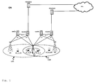
- Fig. 1 shows as an example of a communication network in which the invention can be implemented a communication network CN according to the standard 3GPP LTE.
- Said communication network CN comprises a macro base station MA of a first operator A, a macro base station MB of a second operator B, a pico base station S, a user terminal UE_A_MA registered with the first operator A and served by the macro base station MA of the first operator A, a user terminal UE_B_MB registered with the second operator B and served by the macro base station MB of the second operator B, a user terminal UE_A_S registered with the first operator A and served by the pico base station S, a user terminal UE_B_S registered with the second operator B and served by the pico base station S, serving gateways SGWA and SGWB of the first operator A and the second operator B respectively, packet data network gateways PDNGWA and PDNGWB of the first operator A and the second operator B respectively, and mobility management entities MMEA and MMEB of the first operator A and the second operator B respectively.
- the user terminal UE_A_MA is connected via a radio connection to the macro base station MA
- the user terminals UE_A_S and UE_B_S are connected via radio connections to the pico base station S
- the user terminal UE_B_MB is connected via a radio connection to the macro base station MB.
- each of the user terminals UE_A_MA, UE_B_MB, UE_A_PB and UE_B_PB could also be connected via radio connections to multiple macro and/or pico base stations.
- the macro base station MA is in turn connected to the serving gateway SGWA and to the mobility management entity MMEA, i.e. to the evolved packet core (EPC) of operator A, via a so-called S1 interface.
- EPC evolved packet core
- the macro base station MB is connected to the serving gateway SGWB and to the mobility management entity MMEB, i.e. to the evolved packet core (EPC) of operator B, via an S1 interface.
- the pico base station S is connected to both the serving gateway SGWA and the mobility management entity MMEA of operator A, and the serving gateway SGWB and the mobility management entity MMEB of operator B.
- the serving gateway SGWA is connected to the packet data network gateway PDNGWA, which is in turn connected to an external IP network IPN, and the serving gateway SGWB is connected to the packet data network gateway PDNGWB, which is in turn connected to the external IP network IPN. Furthermore, the serving gateway SGWA is connected to the mobility management entity MMEA via a so-called S11 interface, and the serving gateway SGWB is connected to the mobility management entity MMEB also via a so-called S11 interface.
- the S1 interface is a standardized interface between a base station, i.e. an eNodeB in this example, and the Evolved Packet Core (EPC).
- the S1 interface has two flavours, S1-MME for exchange of signalling messages between one of the base stations MA, MB, and S, and the respective mobility management entity MMEA or MMEB, and S1-U for the transport of user datagrams between one of the base stations MA, MB, and S, and the respective serving gateway SGWA and SGWB.
- the X2 interface is added in 3GPP LTE standard primarily in order to transfer the user plane signal and the control plane signal during handover.
- the serving gateways SGWA and SGWB perform routing of IP user data between a respective base stations MA, MB, or S, and the respective packet data network gateway PDNGWA or PDNGWB. Furthermore, the serving gateways SGWA and SGWB serve as a mobile anchor point during handover either between different base stations, or between different 3GPP access networks.
- EPS Evolved Packet System
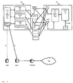
- Fig. 2 schematically shows the structure of a user terminal UE and a base station BS in which the invention can be implemented.
- the base station BS comprises by way of example three modem unit boards MU1-MU3 and a control unit board CU1, which in turn comprises a media dependent adapter MDA.
- the three modem unit boards MU1-MU3 are connected to the control unit board CU1, and to a respective remote radio head RRH1, RRH2, or RRH3 via a so-called Common Public Radio Interface (CPRI).
- CPRI Common Public Radio Interface
- Each of the remote radio heads RRH1, RRH2, and RRH3 is connected by way of example to two remote radio head antennas RRHA1 and RRHA2 for transmission and reception of data via a radio interface. Said two remote radio head antennas RRHA1 and RRHA2 are only depicted for the remote radio head RRH1 in fig. 2 for the sake of simplicity.
- IP data received from the external IP network IPN are transmitted from the packet data network gateway PDNGW via the serving gateway SGW to the media dependent adapter MDA of the base station BS on an EPS bearer.
- the media dependent adapter MDA allows for a connectivity to different media like e.g. fiber or electrical connection.
- the control unit board CU1 performs tasks on layer 3, i.e. on the radio resource control (RRC) layer, such as measurements and cell reselection, handover and RRC security and integrity.
- RRC radio resource control
- PDCP Packet Data Convergence Protocol
- RLC Radio Link Control
- ARQ segmentation and Automatic Repeat Request
- MAC Media Access Control
- the modem unit board MU4 performs data processing on the physical layer, i.e. antenna and resource-block demapping, demodulation and decoding.
- MAC Media Access Control
- RLC Radio Link Control
- ARQ Automatic Repeat Request
- PDCP Packet Data Convergence Protocol
- the processing on the modem unit board MU4 results in IP data which are sent to the control unit board CU2, which performs tasks on layer 3, i.e. on the radio resource control (RRC) layer, such as measurements and cell reselection, handover and RRC security and integrity.
- RRC radio resource control
- the IP data are transmitted from the control unit board CU2 to respective interfaces INT for output and interaction with a user.
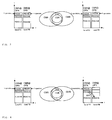
- Fig. 3 schematically shows state of the art resource sharing for two operators with separate schedulers.
- PBCHA and PBCHB respectively are performed comprising an indication of the respective operator OPA or OPB, as e.g. the so-called Public Land Mobile Network identifier (PLMN ID) of the respective operator OPA or OPB.
- PLMN ID Public Land Mobile Network identifier
- Both, user terminals registered at the indicated operator OPA, and user terminals registered at the indicated operator OPB are allowed to get access to the small cells CSA and CSB. Then, in the small cell CSA on the frequency band FA, transmissions on a Physical Downlink Control Channel PDCCHA and on a Physical Downlink Shared Channel PDSCHA are performed, and in the small cell CSB on the frequency band FB, transmissions on a Physical Downlink Control Channel PDCCHB and on a Physical Downlink Shared Channel PDSCHB are performed.
- user terminals getting access to the small cell CSA of operator OPA can only be scheduled to a Physical Downlink Shared Channel PDSCHA in the frequency band FA
- user terminals getting access to the small cell CSB of operator OPB can only be scheduled to a Physical Downlink Shared Channel PDSCHB in the frequency band FB, i.e. no carrier aggregation is performed.
- Fig. 4 schematically shows state of the art resource sharing for two operators OPA and OPB with one scheduler and carrier aggregation.
- the coverage areas of macro cells CMA and CMB and small cells CSA and CSB depicted in the middle of fig. 4 are as depicted in the middle of fig. 3 and described above.
- the Physical Downlink Control Channel PDCCHA comprises an indicator CIFA for allocation of resources on a Physical Downlink Shared Channel PDSCHA of the operator OPA in the frequency band FA, or for allocation of resources on a Physical Downlink Shared Channel PDSCHB of the operator OPB in the frequency band FB.
- Said indicator CIFA can e.g. be a so-called carrier indicator field.
- Both, user terminals registered at the indicated operator OPA, and user terminals registered at the indicated operator OPB can thus be scheduled on resources on a Physical Downlink Shared Channel PDSCHA of the operator OPA in the frequency band FA, or on resources on a Physical Downlink Shared Channel PDSCHB of the operator OPB in the frequency band FB, i.e. carrier aggregation is performed.
- the coverage areas of macro cells CMA and CMB and small cells CSA and CSB depicted in the middle of fig. 5 are as depicted in the middle of fig. 3 and described above.
- PBCHA Physical Broadcast Channel
- PLMN ID Public Land Mobile Network identifier
- PBCHB Physical Broadcast Channel
- a user terminal of operator OPB served by the macro cell CMB moves towards the small cell CSB, it can perform intra-frequency measurements on the PCC in the frequency band FB, which is the same as the carrier of operator OPB in the macro cell CMB.
- FB the carrier of operator OPB in the macro cell CMB.
- all its signalling can be carried over the PCC in the frequency band FB.
- user data can be scheduled over the complete spectrum using the carrier aggregation feature, i.e. over the frequency bands FA and FB.
- An analogue handover procedure is possible for a user terminal of operator OPA served by the macro cell CMA moving towards the small cell CSA.
- the small cells CSA and CSB utilize the resource pooling, i.e. wider spectrum gain, and at the same time maintain the fairness between both operators OPA and OPB, as due to the PCC on each carrier for each operator, user terminals served by a macro base station CMA or CMB from the operator OPA or OPB will perform simply an intra-frequency measurement and handover, as broadcast and control channels are transmitted on the carrier of the respective operator OPA and OPB in the respective small cell CSA and CSB. In this way both operators will benefit from a wider spectrum and both will benefit from reduced re-configurations on the RRC layer.
Landscapes
- Engineering & Computer Science (AREA)
- Computer Networks & Wireless Communication (AREA)
- Signal Processing (AREA)
- Computer Security & Cryptography (AREA)
- Mobile Radio Communication Systems (AREA)
Description
- The invention relates to a method for allocation of frequency resources of different operators to user terminals in a wireless communication network, and a base station and a user terminal adapted to perform said method.
- Radio Access Network (RAN) sharing enables wireless network operators to share resources between different entities, as e.g. between wireless network operators, and thereby reduce their deployment costs. According to the Third Generation Partnership Project Long Term Evolution (3GPP LTE) standard, RAN sharing by multiple operators is supported, as e.g. described in the 3GPP technical report TR 36.300, chapter 10.1.7. To enable RAN sharing in LTE, each cell broadcasts the so-called Public Land Mobile Network identifier (PLMN ID) of each operator, whereby the PLMN IDs for all cells combined in a so-called tracking area are the same, as e.g. described in the 3GPP technical specification TS 23.251, chapter 4.2.2. RAN sharing is based on a multi-to-multi relationship between E-UTRAN nodes (E-UTRAN = Evolved Universal Telecommunications System Terrestrial Radio Access Network), i.e. so-called evolved Node Bs (eNBs), and Evolved Packet Core (EPC) nodes, as e.g. mobility management entities (MMEs), which is realized by the so-called S1-flex concept, as e.g. described in the 3GPP technical report TR 23.882, chapter 7.16.3. During attachment to the network, the user terminals of different operators which are served by the same shared eNB are assigned to different MMEs.
- Document D1, MEDIATEK INC: "Cross-carrier scheduling for carrier-based HetNet ICIC", 3GPP DRAFT; R3-120173, 31 January 2012 discloses proposals for cross-carrier scheduling.
- The sharing of resources can be broadly categorized in three fields: Hard resource sharing, soft resource sharing and the combination of both. The first category refers to the mobile network infrastructure sharing, as e.g. the sharing of the base station, and/or the backhaul network, and/or the core network between the entities. The second category, the soft resources, refers to the sharing of licensed and/or unlicensed, as e.g. white space, frequency spectrum. The third category can share both hard and soft resources and may also have a common controlling/management of the resources. For example a shared radio access network will provide sharing of soft radio resources, as e.g bandwidth, the radio hardware, as e.g. a base station, and also the functional software modules like a scheduler. The combined sharing of both resource types is possible with the help of advanced MAC layer procedures (MAC = Medium Access Control) and RRM procedures (RRM = Radio Resource Management).
- A combined sharing of resources can e.g. be realized in so called Heterogeneous Networks (HetNets). In heterogeneous network (HetNet) scenarios using standards like e.g. a 3GPP LTE standard, so-called pico base stations with their small cells are placed under the coverage of a so-called macro base station. A pico base station typically covers a small area e.g. in buildings, train stations or aircrafts due to its lower power, whereas a macro base station covers a larger area than a pico base station, as e.g. an outdoor area. Pico base stations enable a densification of a wireless cellular network by providing additional capacity to certain HotSpots.
- In a HetNet scenario, an operator may deploy a small cell at a certain hotspot, e.g. a coffee shop, to offload traffic from its macro layer. Depending on the characteristics of this HotSpot different operators could profit from sharing their small cells and thereby reducing CAPEX and OPEX.
- A possible scenario for resource sharing can be a third party, e.g. a shopping mall, an airport, an underground-parking, or a cinema, deploying its own small cell in the coverage area of macro cells, and different operators can take the services to serve their users in the coverage area of the small cell using resources of the small cell of the third party to build their own small cell.
- In the following, 2 state of the art solutions for resource sharing between 2 operators with 2 small cells having an overlapping or equal coverage area is described.
- Assuming that an operator OPA is using a frequency carrier in a frequency band FA. Likewise the other operator OPB is using a frequency carrier in frequency band FB.
- State of the art solution with separate schedulers:
- In this scenario, there are two separate schedulers in the small cells of the 2 operators OPA and OPB, enabling a kind of national roaming, as both frequency bands FA and FB allow access of user terminals with a subscription to operator OPA or operator OPB, as within the Broadcast Control Channel (BCCH) of both small cells, two operator IDs are included. This solution is not sufficient with respect to the efficient radio resource management, as no so-called resource pooling is used in the small cells.
- State of the art solution with one scheduler and with carrier aggregation:
- In this case, the operators OPA and OPB share the complete radio access network. With the help of so-called carrier aggregation, the two carriers, i.e. frequency bands FA and FB, can be combined in the small cell coverage area to serve the user terminals of both operators OPA and OPB using the aggregated frequency resources. For this purpose, only one carrier can be assigned as a so-called primary component carrier (PCC) and the other can be used as a so-called secondary component carrier (SCC). With the help of cross carrier scheduling, a common scheduler with a BCCH only on the PCC utilizes the complete spectrum and allocates the resource to the user terminals of both operators OPA and OPB. This solution is maybe sufficient with respect to the efficient radio resource management. However, it does not guarantee the fairness between the operators OPA and OPB. Let the carrier from the operator OPA be taken as PCC and the carrier from the operator OPB serve as SCC. In this case, the handover of user terminals of a macro cell of operator OPA to the small cell will be an intra-frequency handover, as broadcast and control channels are transmitted on the carrier of operator OPA in the small cell. On the other hand, the handover of user terminals of a macro cell of the operator OPB to the small cell will be an inter-frequency handover. Thus, the operator OPB has to bear high costs for the resource sharing by configuring its user terminals for inter-frequency measurements, i.e. measurement gaps are required for measurement of the frequency band FA of the other operator OPA.
- The object of the invention is thus to propose a method for resource sharing between operators with a good and flexible usage of the common frequency resources and at the same time maintaining the fairness between both operators.
- The basic idea of embodiments of the invention is to serve user terminals from at least two different operators based on an enhanced carrier aggregation principle preferably by one hardware platform, e.g. an LTE pico or macro base station. The hardware platform transmits at least two broadcast and control channels, as e.g. a so-called Physical Broadcast Channel (PBCH) and a Physical Downlink Control Channel (PDCCH), on at least two operator specific frequency bands and enables the scheduling of all user terminals independently of their operator subscription on the at least two frequency bands.
- In a preferred embodiment, for two different operators, two PCC are used, one for each operator in a small cell coverage area, and a common hardware with two different cell IDs and two PBCHs for the two operators are used. Using the carrier aggregation and cross carrier scheduling, a common small cell scheduler will serve the user terminals of the two operators. With this method, the small cells of the two operators utilize the resource pooling, i.e. wider spectrum gain, and at the same time maintain the fairness between both operators. Due to the PCC on each carrier for each operator, user terminals in macro cells from either operator will perform simply an intra-frequency measurement and intra-frequency handover. In this way both operators will benefit from a wider spectrum and both will benefit from the reduced re-configurations on the Radio Resource Control (RRC) layer.
- The object is thus achieved by a method for allocation of frequency resources of different operators to user terminals in a wireless communication network, wherein
- on at least one frequency resource of each operator of said different operators, an indication of said operator allowing user terminals registered at said operator to get access to a signaled cell is transmitted on a broadcast channel,
- user terminals receive control information only on frequency resources of an operator at which they are registered,
- and said control information comprises an indicator allocating to the user terminals at least one frequency resource of said frequency resources of an operator at which the user terminals are not registered.
- The object of the invention is furthermore achieved by a base station for allocation of frequency resources of different operators to user terminals, wherein said base station is adapted
- to transmit on a broadcast channel on at least one frequency resource of each operator of said different operators an indication of said operator allowing user terminals registered at said operator to get access to a signaled cell,
- and to transmit control information to user terminals only on frequency resources of an operator at which said user terminals are registered, said control information comprising an indicator allocating to the user terminals at least one frequency resource of said frequency resources of an operator at which the user terminals are not registered.
- The object of the invention is furthermore achieved by a user terminal to which frequency resources of different operators can be allocated, wherein said user terminal is adapted to
- receive on at least one frequency resource of an operator of said different operators at which the user terminal is registered an indication of said operator on a broadcast channel allowing the user terminal to get access to a signaled cell,
- and receive control information only on frequency resources of the operator at which the user terminal is registered, said control information comprising an indicator allocating to the user terminal at least one frequency resource of said frequency resources of an operator at which the user terminal is not registered.
- The invention is described in the following within the framework of 3GPP LTE, however as the invention is not restricted to 3GPP LTE, but can in principle be applied in other networks that can apply a method for allocation of frequency resources of different operators to user terminals, like e.g. in WiMAX networks (WiMAX = Worldwide Interoperability for Microwave Access), in the following, instead of the term eNodeB used in LTE, the more general term base station is used.
- Further developments of the invention can be gathered from the dependent claims and the following description.
- In the following the invention will be explained further making reference to the attached drawings.
-
Fig. 1 schematically shows a communication network in which the invention can be implemented. -
Fig. 2 schematically shows the structure of a user terminal and a base station in which the invention can be implemented. -
Fig. 3 schematically shows state of the art resource sharing for two operators with separate schedulers. -
Fig. 4 schematically shows state of the art resource sharing for two operators with one scheduler and carrier aggregation. -
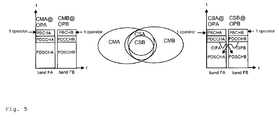
Fig. 5 schematically shows resource sharing for two operators with one scheduler, carrier aggregation, and separate broadcast and control channels according to an embodiment of the invention. -
Fig. 1 shows as an example of a communication network in which the invention can be implemented a communication network CN according to the standard 3GPP LTE. - Said communication network CN comprises a macro base station MA of a first operator A, a macro base station MB of a second operator B, a pico base station S, a user terminal UE_A_MA registered with the first operator A and served by the macro base station MA of the first operator A, a user terminal UE_B_MB registered with the second operator B and served by the macro base station MB of the second operator B, a user terminal UE_A_S registered with the first operator A and served by the pico base station S, a user terminal UE_B_S registered with the second operator B and served by the pico base station S, serving gateways SGWA and SGWB of the first operator A and the second operator B respectively, packet data network gateways PDNGWA and PDNGWB of the first operator A and the second operator B respectively, and mobility management entities MMEA and MMEB of the first operator A and the second operator B respectively.
- The user terminal UE_A_MA is connected via a radio connection to the macro base station MA, the user terminals UE_A_S and UE_B_S are connected via radio connections to the pico base station S, and the user terminal UE_B_MB is connected via a radio connection to the macro base station MB. In future evolutions of LTE, each of the user terminals UE_A_MA, UE_B_MB, UE_A_PB and UE_B_PB could also be connected via radio connections to multiple macro and/or pico base stations. The macro base station MA is in turn connected to the serving gateway SGWA and to the mobility management entity MMEA, i.e. to the evolved packet core (EPC) of operator A, via a so-called S1 interface. In the same way, the macro base station MB is connected to the serving gateway SGWB and to the mobility management entity MMEB, i.e. to the evolved packet core (EPC) of operator B, via an S1 interface. The pico base station S is connected to both the serving gateway SGWA and the mobility management entity MMEA of operator A, and the serving gateway SGWB and the mobility management entity MMEB of operator B.
- The serving gateway SGWA is connected to the packet data network gateway PDNGWA, which is in turn connected to an external IP network IPN, and the serving gateway SGWB is connected to the packet data network gateway PDNGWB, which is in turn connected to the external IP network IPN. Furthermore, the serving gateway SGWA is connected to the mobility management entity MMEA via a so-called S11 interface, and the serving gateway SGWB is connected to the mobility management entity MMEB also via a so-called S11 interface.
- The macro base stations MA and MB are connected to the pico base station S via a so-called X2 interface, which is not shown in
fig. 1 for the sake of simplicity. The macro base stations MA and MB can be connected to the pico base station S via radio connections or via fixed line connections. - The S1 interface is a standardized interface between a base station, i.e. an eNodeB in this example, and the Evolved Packet Core (EPC). The S1 interface has two flavours, S1-MME for exchange of signalling messages between one of the base stations MA, MB, and S, and the respective mobility management entity MMEA or MMEB, and S1-U for the transport of user datagrams between one of the base stations MA, MB, and S, and the respective serving gateway SGWA and SGWB.
- The X2 interface is added in 3GPP LTE standard primarily in order to transfer the user plane signal and the control plane signal during handover.
- The serving gateways SGWA and SGWB perform routing of IP user data between a respective base stations MA, MB, or S, and the respective packet data network gateway PDNGWA or PDNGWB. Furthermore, the serving gateways SGWA and SGWB serve as a mobile anchor point during handover either between different base stations, or between different 3GPP access networks.
- The packet data network gateways PDNGWA and PDNGWB represent the interface to the external IP network IPN and terminate the so-called EPS bearer (EPS = Evolved Packet System) which is established between a user terminal UE_A_MA, UE_B_MB, UE_A_S or UE_B_S and the respective serving macro base station MA or MB or pico base station S.
- The mobility management entities MMEA and MMEB perform tasks of the subscriber management and the session management, and also perform the mobility management during handover between different access networks.
- The pico base station S and the related coverage area CS of the pico cell are placed under the coverage area CMA of the macro base station MA and under the coverage area CMB of the macro base station MB.
-
Fig. 2 schematically shows the structure of a user terminal UE and a base station BS in which the invention can be implemented. - The base station BS comprises by way of example three modem unit boards MU1-MU3 and a control unit board CU1, which in turn comprises a media dependent adapter MDA.
- The three modem unit boards MU1-MU3 are connected to the control unit board CU1, and to a respective remote radio head RRH1, RRH2, or RRH3 via a so-called Common Public Radio Interface (CPRI).
- Each of the remote radio heads RRH1, RRH2, and RRH3 is connected by way of example to two remote radio head antennas RRHA1 and RRHA2 for transmission and reception of data via a radio interface. Said two remote radio head antennas RRHA1 and RRHA2 are only depicted for the remote radio head RRH1 in
fig. 2 for the sake of simplicity. - The media dependent adapter MDA is connected to the mobility management entity MME and to the serving gateway SGW and thus to the packet data network gateway PDNGW, which is in turn connected to the external IP network IPN.
- The user terminal UE comprises by way of example two user terminal antennas UEA1 and UEA2, a modem unit board MU4, a control unit board CU2, and interfaces INT.
- The two user terminal antennas UEA1 and UEA2 are connected to the modem unit board MU4. The modem unit board MU4 is connected to the control unit board CU2, which is in turn connected to interfaces INT.
- The modem unit boards MU1-MU4 and the control unit boards CU1, CU2 may comprise by way of example Field Programmable Gate Arrays (FPGA), Digital Signal Processors (DSP), micro processors, switches and memories, like e.g. Double Data Rate Synchronous Dynamic Random Access Memories (DDR-SDRAM) in order to be enabled to perform the tasks described below.
- The remote radio heads RRH1, RRH2, and RRH3 comprise the so-called radio equipment, e.g. modulators and amplifiers, like delta-sigma modulators (DSM) and switch mode amplifiers.
- In downlink, IP data received from the external IP network IPN are transmitted from the packet data network gateway PDNGW via the serving gateway SGW to the media dependent adapter MDA of the base station BS on an EPS bearer. The media dependent adapter MDA allows for a connectivity to different media like e.g. fiber or electrical connection.
- The control unit board CU1 performs tasks on layer 3, i.e. on the radio resource control (RRC) layer, such as measurements and cell reselection, handover and RRC security and integrity.
- Furthermore, the control unit board CU1 performs tasks for Operation and Maintenance, and controls the S1 interfaces, the X2 interfaces, and the Common Public Radio Interface.
- The control unit board CU1 sends the IP data received from the serving gateway SGW to a modem unit board MU1-MU3 for further processing.
- The three modem unit boards MU1-MU3 perform data processing on layer 2, i.e. on the PDCP layer (PDCP = Packet Data Convergence Protocol) which is e.g. responsible for header compression and ciphering, on the RLC layer (RLC = Radio Link Control) which is e.g. responsible for segmentation and Automatic Repeat Request (ARQ), and on the MAC layer (MAC = Media Access Control) which is responsible for MAC multiplexing and Hybrid Automatic Repeat Request (HARQ).
- Furthermore, the three modem unit boards MU1-MU3 perform data processing on the physical layer, i.e. coding, modulation, and antenna and resource-block mapping.
- The coded and modulated data are mapped to antennas and resource blocks and are sent as transmission symbols from the modem unit board MU1-MU3 over the Common Public Radio Interface to the respective remote radio head RRH1, RRH2, or RRH3, and the respective remote radio head antenna RRHA1, RRHA2 for transmission over an air interface.
- The Common Public Radio Interface (CPRI) allows the use of a distributed architecture where base stations BS, containing the so-called radio equipment control, are connected to remote radio heads RRH1, RRH2, and RRH3 preferably via lossless fibre links that carry the CPRI data. This architecture reduces costs for service providers because only the remote radio heads RRH1, RRH2, and RRH3 containing the so-called radio equipment, like e.g. amplifiers, need to be situated in environmentally challenging locations. The base stations BS can be centrally located in less challenging locations where footprint, climate, and availability of power are more easily managed.
- The user terminal antennas UEA1, UEA2 receive the transmission symbols, and provide the received data to the modem unit board MU4.
- The modem unit board MU4 performs data processing on the physical layer, i.e. antenna and resource-block demapping, demodulation and decoding.
- Furthermore, the modem unit board MU4 performs data processing on layer 2, i.e. on the MAC layer (MAC = Media Access Control) which is responsible for Hybrid Automatic Repeat Request (HARQ) and for MAC demultiplexing, on the RLC layer (RLC = Radio Link Control) which is e.g. responsible for reassembly and Automatic Repeat Request (ARQ), and on the PDCP layer (PDCP = Packet Data Convergence Protocol) which is e.g. responsible for deciphering and header compression.
- The processing on the modem unit board MU4 results in IP data which are sent to the control unit board CU2, which performs tasks on layer 3, i.e. on the radio resource control (RRC) layer, such as measurements and cell reselection, handover and RRC security and integrity.
- The IP data are transmitted from the control unit board CU2 to respective interfaces INT for output and interaction with a user.
- In the uplink, data transmission is performed in an analogue way in the reverse direction from the user terminal UE to the external IP network IPN.
- In the sequel, methods for resource sharing between operators in a wireless communication network as depicted in
fig. 1 are described according to the state of the art infigs. 3 and 4 , and according to an embodiment of the invention infig. 5 . -
Fig. 3 schematically shows state of the art resource sharing for two operators with separate schedulers. - In the middle of
fig. 3 , the coverage areas of the macro cells CMA and CMB served by the macro base station MA of a first operator OPA and the macro base station MB of a second operator OPB are depicted. In the region where the two coverage areas are overlapping, also the coverage area of a small cell CSA of the first operator OPA and the coverage area of a small cell CSB of the second operator OPB are depicted. - On the left in
fig. 3 , different channels are depicted for the macro cell CMA of the first operator OPA in the frequency band FA, and for the macro cell CMB of the second operator OPB in the frequency band FB. First, transmission on a Physical Broadcast Channel PBCHA and PBCHB respectively is performed comprising an indication of the respective operator OPA or OPB, as e.g. the so-called Public Land Mobile Network identifier (PLMN ID) of the respective operator OPA or OPB. Thus, in the macro cell CMA of the first operator OPA, on the Physical Broadcast Channel PBCHA, an indication of the operator OPA is transmitted, and in the macro cell CMB of the second operator OPB, on the Physical Broadcast Channel PBCHB, an indication of the operator OPB is transmitted. Only user terminals registered at the indicated operator OPA are allowed to get access to the macro cell CMA, and only user terminals registered at the indicated operator OPB are allowed to get access to the macro cell CMB. Then, in the macro cell CMA on the frequency band FA, transmissions on a Physical Downlink Control Channel PDCCHA and on a Physical Downlink Shared Channel PDSCHA are performed, and in the macro cell CMB on the frequency band FB, transmissions on a Physical Downlink Control Channel PDCCHB and on a Physical Downlink Shared Channel PDSCHB are performed. - On the right in
fig. 3 , different channels are depicted for the small cell CSA of the first operator OPA in the frequency band FA, and for the small cell CSB of the second operator OPB in the frequency band FB. First, transmission on a Physical Broadcast Channel PBCHA and PBCHB respectively is performed comprising an indication of both operators OPA and OPB, as e.g. the so-called Public Land Mobile Network identifiers (PLMN ID) of the operators OPA and OPB, in each broadcast channel PBCHA and PBCHB. Thus, in the small cell CSA of the first operator OPA, on the Physical Broadcast Channel PBCHA, an indication of both operators OPA and OPB is transmitted, and in the small cell CSB of the second operator OPB, on the Physical Broadcast Channel PBCHB, also an indication of both operators OPA and OPB is transmitted. - Both, user terminals registered at the indicated operator OPA, and user terminals registered at the indicated operator OPB are allowed to get access to the small cells CSA and CSB. Then, in the small cell CSA on the frequency band FA, transmissions on a Physical Downlink Control Channel PDCCHA and on a Physical Downlink Shared Channel PDSCHA are performed, and in the small cell CSB on the frequency band FB, transmissions on a Physical Downlink Control Channel PDCCHB and on a Physical Downlink Shared Channel PDSCHB are performed.
- However, user terminals getting access to the small cell CSA of operator OPA can only be scheduled to a Physical Downlink Shared Channel PDSCHA in the frequency band FA, and user terminals getting access to the small cell CSB of operator OPB can only be scheduled to a Physical Downlink Shared Channel PDSCHB in the frequency band FB, i.e. no carrier aggregation is performed.
- In this scenario, there are two separate schedulers in the small cells CSA and CSB of the 2 operators OPA and OPB, enabling a kind of national roaming, as both frequency bands FA and FB allow access of user terminals with a subscription to operator OPA or operator OPB, as within the Broadcast Control Channel (BCCH) of both small cells CSA and CSB, two operator IDs are included. This solution is however not sufficient with respect to the efficient radio resource management, as no so-called resource pooling is used in the small cells CSA and CSB.
-
Fig. 4 schematically shows state of the art resource sharing for two operators OPA and OPB with one scheduler and carrier aggregation. - The coverage areas of macro cells CMA and CMB and small cells CSA and CSB depicted in the middle of
fig. 4 are as depicted in the middle offig. 3 and described above. - The different channels depicted for the macro cell CMA of the first operator OPA in the frequency band FA, and for the macro cell CMB of the second operator OPB in the frequency band FB on the left in
fig. 4 are as depicted on the left infig. 3 and described above. - On the right in
fig. 4 , different channels are depicted for the small cell CSA of the first operator OPA in the frequency band FA, and for the small cell CSB of the second operator OPB in the frequency band FB. First, transmission on a Physical Broadcast Channel PBCHA only in the small cell CSA of the first operator OPA is performed comprising an indication of both operators OPA and OPB, as e.g. the so-called Public Land Mobile Network identifiers (PLMN ID) of the operators OPA and OPB. Thus, in the small cell CSA of the first operator OPA, on the Physical Broadcast Channel PBCHA, an indication of both operators OPA and OPB is transmitted, and in the small cell CSB of the second operator OPB, neither a Physical Broadcast Channel PBCHB, nor a Physical Downlink Control Channel PDCCHB is available for transmission. - Both, user terminals registered at the indicated operator OPA, and user terminals registered at the indicated operator OPB are allowed to get access to the small cell CSA. Then, in the small cell CSA on the frequency band FA, transmissions on a Physical Downlink Control Channel PDCCHA are performed. The Physical Downlink Control Channel PDCCHA comprises an indicator CIFA for allocation of resources on a Physical Downlink Shared Channel PDSCHA of the operator OPA in the frequency band FA, or for allocation of resources on a Physical Downlink Shared Channel PDSCHB of the operator OPB in the frequency band FB. Said indicator CIFA can e.g. be a so-called carrier indicator field. Both, user terminals registered at the indicated operator OPA, and user terminals registered at the indicated operator OPB can thus be scheduled on resources on a Physical Downlink Shared Channel PDSCHA of the operator OPA in the frequency band FA, or on resources on a Physical Downlink Shared Channel PDSCHB of the operator OPB in the frequency band FB, i.e. carrier aggregation is performed.
- In this case, the operators OPA and OPB share the complete radio access network. With the help of so-called carrier aggregation, the two carriers, i.e. frequency bands FA and FB, can be combined in the small cell coverage area to serve the user terminals of both operators OPA and OPB using the aggregated frequency resources. For this purpose, only one carrier can be assigned as a so-called primary component carrier (PCC) and the other can be used as a so-called secondary component carrier (SCC). With the help of cross carrier scheduling, a common scheduler with a BCCH only on the PCC utilizes the complete spectrum and allocates the resource to the user terminals of both operators OPA and OPB. This solution could be seen as sufficient with respect to an efficient radio resource management, as resource pooling is used. However, it does not guarantee the fairness between the operators OPA and OPB. Let the carrier from the operator OPA be taken as PCC and the carrier from the operator OPB serve as SCC. In this case, the handover of user terminals of the macro cell CMA of operator OPA to the small cell CSA will be an intra-frequency handover, as broadcast and control channels are transmitted on the carrier of operator OPA in the small cell CSA. On the other hand, the handover of user terminals of the macro cell CMB of the operator OPB to the small cell CSB will be an inter-frequency handover, as broadcast and control channels are only transmitted on the carrier of operator OPA, i.e. on the frequency band FA. Thus, the operator OPB has to bear high costs for the resource sharing by configuring its user terminals for inter-frequency measurements, i.e. measurement gaps are required for measurement of the frequency band FA of the other operator OPA.
-
Fig. 5 schematically shows resource sharing for two operators with one scheduler, carrier aggregation, and separate broadcast and control channels according to an embodiment of the invention. - In
fig. 5 , a method for resource sharing between operators in a wireless communication network as depicted infig. 1 leading to a good and flexible usage of the common frequency resources and at the same time maintaining the fairness between both operators is depicted. - The coverage areas of macro cells CMA and CMB and small cells CSA and CSB depicted in the middle of
fig. 5 are as depicted in the middle offig. 3 and described above. - The different channels depicted for the macro cell CMA of the first operator OPA in the frequency band FA, and for the macro cell CMB of the second operator OPB in the frequency band FB on the left in
fig. 5 are as depicted on the left infig. 3 and described above. - On the right in
fig. 5 , different channels are depicted for the small cell CSA of the first operator OPA in the frequency band FA, and for the small cell CSB of the second operator OPB in the frequency band FB. First, transmission on a Physical Broadcast Channel PBCHA is performed comprising an indication of the operator OPA, as e.g. the so-called Public Land Mobile Network identifier (PLMN ID) of the operator OPA, in the broadcast channel PBCHA, and transmission on a Physical Broadcast Channel PBCHB is performed comprising an indication of the operator OPB, as e.g. the so-called Public Land Mobile Network identifier (PLMN ID) of the operator OPB, in the broadcast channel PBCHB. - Thus, user terminals registered at the indicated operator OPA are allowed to get access to the small cell CSA, and user terminals registered at the indicated operator OPB are allowed to get access to the small cell CSB. Then, in the small cell CSA on the frequency band FA, transmissions on a Physical Downlink Control Channel PDCCHA are performed. The Physical Downlink Control Channel PDCCHA comprises an indicator CIFA for allocation of resources on a Physical Downlink Shared Channel PDSCHA of the operator OPA in the frequency band FA, or for allocation of resources on a Physical Downlink Shared Channel PDSCHB of the operator OPB in the frequency band FB. Said indicator CIFA can e.g. be a so-called carrier indicator field. User terminals registered at the indicated operator OPA can be scheduled on resources on a Physical Downlink Shared Channel PDSCHA of the operator OPA in the frequency band FA, or on resources on a Physical Downlink Shared Channel PDSCHB of the operator OPB in the frequency band FB, i.e. carrier aggregation is performed. In an analogue way, in the small cell CSB on the frequency band FB, transmissions on a Physical Downlink Control Channel PDCCHB are performed. The Physical Downlink Control Channel PDCCHB comprises an indicator CIFB for allocation of resources on a Physical Downlink Shared Channel PDSCHA of the operator OPA in the frequency band FA, or for allocation of resources on a Physical Downlink Shared Channel PDSCHB of the operator OPB in the frequency band FB. Said indicator CIFB can e.g. be a so-called carrier indicator field. User terminals registered at the indicated operator OPB can be scheduled on resources on a Physical Downlink Shared Channel PDSCHA of the operator OPA in the frequency band FA, or on resources on a Physical Downlink Shared Channel PDSCHB of the operator OPB in the frequency band FB, i.e. carrier aggregation is performed.
- In a preferred embodiment of the invention, it is proposed to have two PCC, one for each operator OPA and OPB in the small cell coverage area using a common hardware with two different cell IDs and two BCCHs for the two operators OPA and OPB. Using the carrier aggregation and cross carrier scheduling as depicted in
fig. 5 and described above, a common small cell scheduler will serve the user terminals of both operators OPA and OPB. - If a user terminal of operator OPB served by the macro cell CMB moves towards the small cell CSB, it can perform intra-frequency measurements on the PCC in the frequency band FB, which is the same as the carrier of operator OPB in the macro cell CMB. Once said user terminal of operator OPB is associated with the small cell CSB, all its signalling can be carried over the PCC in the frequency band FB. However, user data can be scheduled over the complete spectrum using the carrier aggregation feature, i.e. over the frequency bands FA and FB. An analogue handover procedure is possible for a user terminal of operator OPA served by the macro cell CMA moving towards the small cell CSA.
- With the above-described method according to an embodiment of the invention, the small cells CSA and CSB utilize the resource pooling, i.e. wider spectrum gain, and at the same time maintain the fairness between both operators OPA and OPB, as due to the PCC on each carrier for each operator, user terminals served by a macro base station CMA or CMB from the operator OPA or OPB will perform simply an intra-frequency measurement and handover, as broadcast and control channels are transmitted on the carrier of the respective operator OPA and OPB in the respective small cell CSA and CSB. In this way both operators will benefit from a wider spectrum and both will benefit from reduced re-configurations on the RRC layer.
- In the embodiments described above and depicted in
fig. 5 , the corresponding processing steps can be performed e.g. in the modem unit boards MU1-MU3 and the control unit board CU1 of a pico base station of the small cells CSA and CSB, and in the modem unit board MU4 and the control unit board CU2 of the user terminals UE_A_MA, UE_B_MB, UE_A_S and UE_B_S as depicted infigs. 1 ,2 and5 , and described above. - A comparative tabular analysis of the embodiment of the invention depicted in
fig. 5 and the state of the art solutions depicted infigs. 3 and 4 for resource sharing in the small cells CSA and CSB is summarized in the following table.#Cell IDs / #BCCHs operator specific UE handling e.g. signalling in shared cell or measurement configurations #Operators in BCCH Need of Inter-freq. handover measurements Operator specific settings kept (measurements, mobility) Pooling gain #Schedulers #Hardware boxes Fig. 3 2 - 2 XX X - 2 1 Fig. 4 1 - 2 X - X 1 1 Fig. 5 2 X 1 - X X 1 1 - The state of the art solution in
fig. 3 , and the embodiment of the invention infig. 5 both have two cell IDs and BCCHs respectively for the small cells CSA and CSB, whereas the state of the art solution infig. 4 has only one cell ID and BCCH for the small cells CSA and CSB. - The state of the art solutions in
figs. 3 and 4 do not offer an operator specific user terminal handling, as e.g. all user terminals must perform the same handover measurements on the same frequency bands. The embodiment of the invention infig. 5 however offers an operator specific user terminal handling, as e.g. user terminals of operator OPA perform handover measurements in the frequency band FA, whereas user terminals of operator OPB perform handover measurements in the frequency band FB. - The state of the art solutions in
figs. 3 and 4 signal two operator IDs per BCCH in the small cells CSA and CSB, whereas the embodiment of the invention infig. 5 signals only one operator ID per BCCH in the small cells CSA and CSB. - In the state of the art solutions in
figs. 3 and 4 , there is a need for inter-frequency handover measurements, as at least user terminals from one operator must perform measurements in a frequency band of the other operator. In the embodiment of the invention infig. 5 however, only intra-frequency handover measurements must be performed, i.e. the user terminals only perform measurements in the frequency band of their own operator, which is of course more resource effective. - In the state of the art solution in
fig. 3 , and in the embodiment of the invention infig. 5 , operator specific settings for measurements and mobility can be kept, as e.g. handover measurements and handovers of user terminals can be restricted to frequency bands and cells of the own operator. In the state of the art solution infig. 4 however, at least the user terminals of one operator must perform handover measurements in frequency bands of another operator and thus, operator specific settings for measurements and mobility cannot be kept. - In the state of the art solution in
fig. 3 , no pooling gain is achieved, as no carrier aggregation of frequency bands FA and FB is performed for scheduling user terminals, whereas in the state of the art solution infig. 4 , and in the embodiment of the invention infig. 5 , carrier aggregation of frequency bands FA and FB is performed, and thus, a pooling gain is achieved. - In the state of the art solution in
fig. 3 , a separate scheduler for each of the small cells CSA and CSB is used, whereas in the state of the art solution infig. 4 , and in the embodiment of the invention infig. 5 , a common scheduler for both small cells CSA and CSB can be used. - In both state of the art solutions in
figs. 3 and 4 , and in the embodiment of the invention infig. 5 only 1 hardware box, as e.g. only one LTE pico base station can be used for implementing the functionalities of both small cells CSA and CSB.
Claims (10)
- A method for allocation of frequency resources (FA, FB) of different operators (OPA, OPB) to user terminals (UE_A_S, UE_B_S) in a wireless communication network (CN), wherein• on at least one frequency resource (FA, FB) of each operator (OPA, OPB) of said different operators, an indication of said operator allowing user terminals (UE_A_S, UE_B_S) registered at said operator (OPA, OPB) to get access to a signaled cell (CS, CSA, CSB) is transmitted on a broadcast channel (PBCHA, PBCHB),• user terminals (UE_A_S, UE_B_S) receive control information only on frequency resources (FA, FB) of an operator (OPA, OPB) at which the user terminals (UE_A_S, UE_B_S) are registered, characterised in that• said control information comprises an indicator (CIFA, CIFB) allocating to the user terminals (UE_A_S, UE_B_S) at least one frequency resource (FA, FB) of said frequency resources of an operator (OPA, OPB) at which the user terminals (UE_A_S, UE_B_S) are not registered.
- A method according to claim 1, wherein a common scheduler for at least two operators (OPA, OPB) of said different operators is used for the allocation of the frequency resources (FA,FB) of said at least two operators (OPA, OPB).
- A method according to claim 1 or 2, wherein said allocation of the frequency resources (FA, FB) of the different operators (OPA, OPB) to the user terminals (UE_A_S, UE_B_S) is performed in a small cell (CS, CSA, CSB) that is shared between said different operators (OPA, OPB).
- A method according to any of the preceding claims, wherein each of said different operators (OPA, OPB) uses at least one of a group of a dedicated cell identifier and a dedicated broadcast channel (PBCHA, PBCHB).
- A method according to any of the preceding claims, wherein the indicator (CIFA, CIFB) allocating to the user terminals (UE_A_S, UE_B_S) at least one frequency resource (FA, FB) of said frequency resources of an operator (OPA, OPB) at which the user terminals (UE_A_S, UE_B_S) are not registered is comprised in a carrier indicator field of a control channel (PDCCHA, PDCCHB).
- A method according to any of the preceding claims, wherein at least one frequency resource (FA, FB) of an operator (OPA, OPB) of said different operators is used as primary component carrier for said operator, and at least one frequency resource (FA, FB) of at least one further operator (OPA, OPB) of said different operators is used as secondary component carrier.
- A method according to claim 3, wherein a user terminal (UE_A_MA, UE_B_MB) performs handover measurements for performing a handover to the small cell (CS, CSA, CSB) only on frequency resources (FA, FB) of the operator (OPA, OPB) at which it is registered.
- A base station (S, BS) for allocation of frequency resources (FA, FB) of different operators (OPA, OPB) to user terminals (UE_A_S, UE_B_S), wherein said base station (S, BS) is adapted• to transmit on a broadcast channel (PBCHA, PBCHB) on at least one frequency resource (FA, FB) of each operator (OPA, OPB) of said different operators an indication of said operator (OPA, OPB) allowing user terminals (UE_A_S, UE_B_S) registered at said operator (OPA, OPB) to get access to a signaled cell (CS, CSA, CSB),• and to transmit control information to user terminals (UE_A_S, UE_B_S) only on frequency resources (FA, FB) of an operator (OPA, OPB) at which said user terminals (UE_A_S, UE_B_S) are registered, characterised by said control information comprising an indicator (CIFA, CIFB) allocating to the user terminals (UE_A_S, UE_B_S) at least one frequency resource (FA, FB) of said frequency resources of an operator (OPA, OPB) at which the user terminals (UE_A_S, UE_B_S) are not registered.
- A user terminal (UE_A_S, UE_B_S) to which frequency resources (FA, FB) of different operators (OPA, OPB) can be allocated, wherein said user terminal (UE_A_S, UE_B_S) is adapted to• receive on at least one frequency resource (FA, FB) of an operator (OPA, OPB) of said different operators at which the user terminal (UE_A_S, UE_B_S) is registered an indication of said operator (OPA, OPB) on a broadcast channel (PBCHA, PBCHB) allowing the user terminal (UE_A_S, UE_B_S) to get access to a signaled cell (CS, CSA, CSB),• and receive control information only on frequency resources (FA, FB) of the operator (OPA, OPB) at which the user terminal (UE_A_S, UE_B_S) is registered, characterised by said control information comprising an indicator (CIFA, CIFB) allocating to the user terminal (UE_A_S, UE_B_S) at least one frequency resource (FA, FB) of said frequency resources of an operator (OPA, OPB) at which the user terminal (UE_A_S, UE_B_S) is not registered.
- A communication network (CN) for mobile communication comprising at least one base station (S, BS) according to claim 8.
Priority Applications (6)
| Application Number | Priority Date | Filing Date | Title |
|---|---|---|---|
| EP13305525.1A EP2797364B1 (en) | 2013-04-22 | 2013-04-22 | A method for allocation of frequency resources of different operators to user terminals, and a base station and a user terminal therefor |
| TW103108165A TWI526104B (en) | 2013-04-22 | 2014-03-10 | A method for allocation of frequency resources of different operators to user terminals, and a base station and a user terminal therefor |
| PCT/EP2014/055259 WO2014173586A1 (en) | 2013-04-22 | 2014-03-17 | A method for allocation of frequency resources of different operators to user terminals, and a base station and a user terminal therefor |
| US14/785,892 US20160073406A1 (en) | 2013-04-22 | 2014-03-17 | A method for allocation of frequency resources of different operators to user terminals, and a base station and a user terminal therefor |
| CN201480022703.2A CN105122892A (en) | 2013-04-22 | 2014-03-17 | A method for allocation of frequency resources of different operators to user terminals, and a base station and a user terminal therefor |
| JP2016509344A JP6273351B2 (en) | 2013-04-22 | 2014-03-17 | Method for allocation of frequency resources of different operators to user terminals, and base station and user terminal therefor |
Applications Claiming Priority (1)
| Application Number | Priority Date | Filing Date | Title |
|---|---|---|---|
| EP13305525.1A EP2797364B1 (en) | 2013-04-22 | 2013-04-22 | A method for allocation of frequency resources of different operators to user terminals, and a base station and a user terminal therefor |
Publications (2)
| Publication Number | Publication Date |
|---|---|
| EP2797364A1 EP2797364A1 (en) | 2014-10-29 |
| EP2797364B1 true EP2797364B1 (en) | 2016-04-13 |
Family
ID=48520860
Family Applications (1)
| Application Number | Title | Priority Date | Filing Date |
|---|---|---|---|
| EP13305525.1A Not-in-force EP2797364B1 (en) | 2013-04-22 | 2013-04-22 | A method for allocation of frequency resources of different operators to user terminals, and a base station and a user terminal therefor |
Country Status (6)
| Country | Link |
|---|---|
| US (1) | US20160073406A1 (en) |
| EP (1) | EP2797364B1 (en) |
| JP (1) | JP6273351B2 (en) |
| CN (1) | CN105122892A (en) |
| TW (1) | TWI526104B (en) |
| WO (1) | WO2014173586A1 (en) |
Families Citing this family (10)
| Publication number | Priority date | Publication date | Assignee | Title |
|---|---|---|---|---|
| US10615499B2 (en) * | 2015-01-14 | 2020-04-07 | Skywave Mobile Communications Inc. | Dual role antenna assembly |
| US9973350B2 (en) | 2015-05-28 | 2018-05-15 | Industrial Technology Research Institute | Method for network sharing of multiple network operators and network sharing management proxy device using the same |
| CN108156607B (en) * | 2016-12-05 | 2021-04-13 | 中国电信股份有限公司 | Frequency priority information processing method and system and related equipment |
| US10805058B2 (en) * | 2016-12-19 | 2020-10-13 | Cable Television Laboratories, Inc. | Systems and methods for mapping and demapping digitized signals for optical transmission |
| US10566994B2 (en) | 2016-12-19 | 2020-02-18 | Cable Television Laboratories, Inc. | System and methods for virtualizing delta sigma digitization |
| US10763963B2 (en) | 2016-12-19 | 2020-09-01 | Cable Television Laboratories, Inc | System and methods for efficient digitization in hybrid fiber-coaxial networks |
| CN110393023A (en) * | 2017-07-28 | 2019-10-29 | Oppo广东移动通信有限公司 | Send method, the network equipment and the terminal device of system information |
| CN114885299A (en) * | 2021-02-05 | 2022-08-09 | 中国移动通信有限公司研究院 | Flow information processing method, related device and readable storage medium |
| WO2023248292A1 (en) * | 2022-06-20 | 2023-12-28 | 株式会社Nttドコモ | Terminal, radio communication method, and base station |
| US20240106582A1 (en) * | 2022-09-27 | 2024-03-28 | Qualcomm Incorporated | Dynamic carrier sharing techniques for radio unit sharing |
Family Cites Families (9)
| Publication number | Priority date | Publication date | Assignee | Title |
|---|---|---|---|---|
| KR100922982B1 (en) * | 2005-01-27 | 2009-10-22 | 삼성전자주식회사 | Method for transmitting/receiving network sharing information for neighbouring cells in network sharing system and system therefor |
| EP2341678A1 (en) * | 2010-01-05 | 2011-07-06 | Panasonic Corporation | Signaling of resource assignments in cross-carrier scheduling scenarios |
| CN106160992B (en) * | 2010-02-12 | 2020-07-03 | 交互数字专利控股公司 | Method and network for enhancing cell edge performance of wireless transmit/receive unit |
| CN102378201B (en) * | 2010-08-16 | 2016-03-23 | 株式会社Ntt都科摩 | The management method of the community under a kind of carrier aggregation environment and management devices |
| US9392420B2 (en) * | 2010-12-17 | 2016-07-12 | Telefonaktiebolaget L M Ericsson (Publ) | Closed subscriber group (CSG) handling for supporting network sharing of home base stations |
| EP2493235A1 (en) * | 2011-02-25 | 2012-08-29 | Alcatel Lucent | Scheduling of data on shared radio resources |
| WO2012141628A1 (en) * | 2011-04-13 | 2012-10-18 | Telefonaktiebolaget L M Ericsson (Publ) | Method and apparatus for sharing radio network infrastructure using carrier aggregation |
| CN102202398A (en) * | 2011-05-18 | 2011-09-28 | 中兴通讯股份有限公司 | Carrier resource allocation method and device of heterogeneous network |
| GB2490968A (en) * | 2011-05-20 | 2012-11-21 | Nec Corp | Sharing radio access networks fairly between multiple operators |
-
2013
- 2013-04-22 EP EP13305525.1A patent/EP2797364B1/en not_active Not-in-force
-
2014
- 2014-03-10 TW TW103108165A patent/TWI526104B/en not_active IP Right Cessation
- 2014-03-17 CN CN201480022703.2A patent/CN105122892A/en active Pending
- 2014-03-17 US US14/785,892 patent/US20160073406A1/en not_active Abandoned
- 2014-03-17 WO PCT/EP2014/055259 patent/WO2014173586A1/en active Application Filing
- 2014-03-17 JP JP2016509344A patent/JP6273351B2/en not_active Expired - Fee Related
Also Published As
| Publication number | Publication date |
|---|---|
| JP6273351B2 (en) | 2018-01-31 |
| US20160073406A1 (en) | 2016-03-10 |
| TWI526104B (en) | 2016-03-11 |
| CN105122892A (en) | 2015-12-02 |
| EP2797364A1 (en) | 2014-10-29 |
| WO2014173586A1 (en) | 2014-10-30 |
| TW201503732A (en) | 2015-01-16 |
| JP2016517246A (en) | 2016-06-09 |
Similar Documents
| Publication | Publication Date | Title |
|---|---|---|
| EP2797364B1 (en) | A method for allocation of frequency resources of different operators to user terminals, and a base station and a user terminal therefor | |
| JP7338748B2 (en) | Source base station, target base station and methods thereof | |
| US10057810B2 (en) | Communication system, cellular base station, and WLAN access point | |
| CN113691994B (en) | Radio access network node and method therefor | |
| EP2741533B1 (en) | A method for inter-cell interference-coordination, and a base station therefor | |
| TW201739302A (en) | A Macro-assisted Multi-Connectivity scheme in multi-RAT cellular systems | |
| EP3100429B1 (en) | Mechanism for 256-qam capable user equipment to operate seamlessly with a node | |
| KR20180013862A (en) | Seamless Movement in 5G and LTE Systems and Devices | |
| EP3804406A1 (en) | 5g interoperability architecture | |
| TWI531261B (en) | A method for performing a handover of a user terminal, and a base station and a user terminal therefor | |
| EP2384049A1 (en) | Transmission of signalling information to a cluster of terminals moving together | |
| KR101879557B1 (en) | User equipment and methods for measurement of reference signal received quality | |
| KR20150140654A (en) | Method for establishing/releasing a mac (medidum access control) entity in a wireless communication system and a device therefor | |
| US20140119311A1 (en) | A method for transmission of reference signals, a base station and a user terminal therefor | |
| US20160021693A1 (en) | Method for establishing a direct communication, and base stations, a gateway and a device therefor | |
| EP3335466A1 (en) | A wireless communications device, a network node and methods therein for measurement reporting in wlan-lte aggregation | |
| JP5872679B2 (en) | Mobile communication system, mobile communication method, and radio base station | |
| EP2542005B1 (en) | A method for signalling allocations of subframes, a base station and a user terminal therefor | |
| JP5755798B2 (en) | Mobile communication system and mobile communication method | |
| EP3035763A1 (en) | A method for usage of radio resources by different communication standards, and a base station and a user terminal therefor | |
| EP2884795B1 (en) | A method for wireless communication using almost blank subframes, and a communication network | |
| KR20160048647A (en) | Methods for transmitting and receiving a data and Apparatuses thereof |
Legal Events
| Date | Code | Title | Description |
|---|---|---|---|
| PUAI | Public reference made under article 153(3) epc to a published international application that has entered the european phase |
Free format text: ORIGINAL CODE: 0009012 |
|
| 17P | Request for examination filed |
Effective date: 20130422 |
|
| AK | Designated contracting states |
Kind code of ref document: A1 Designated state(s): AL AT BE BG CH CY CZ DE DK EE ES FI FR GB GR HR HU IE IS IT LI LT LU LV MC MK MT NL NO PL PT RO RS SE SI SK SM TR |
|
| AX | Request for extension of the european patent |
Extension state: BA ME |
|
| R17P | Request for examination filed (corrected) |
Effective date: 20150429 |
|
| RBV | Designated contracting states (corrected) |
Designated state(s): AL AT BE BG CH CY CZ DE DK EE ES FI FR GB GR HR HU IE IS IT LI LT LU LV MC MK MT NL NO PL PT RO RS SE SI SK SM TR |
|
| REG | Reference to a national code |
Ref country code: DE Ref legal event code: R079 Ref document number: 602013006460 Country of ref document: DE Free format text: PREVIOUS MAIN CLASS: H04W0048100000 Ipc: H04W0024020000 |
|
| RIC1 | Information provided on ipc code assigned before grant |
Ipc: H04W 24/02 20090101AFI20150821BHEP Ipc: H04W 48/10 20090101ALI20150821BHEP |
|
| GRAP | Despatch of communication of intention to grant a patent |
Free format text: ORIGINAL CODE: EPIDOSNIGR1 |
|
| INTG | Intention to grant announced |
Effective date: 20160114 |
|
| GRAS | Grant fee paid |
Free format text: ORIGINAL CODE: EPIDOSNIGR3 |
|
| GRAA | (expected) grant |
Free format text: ORIGINAL CODE: 0009210 |
|
| AK | Designated contracting states |
Kind code of ref document: B1 Designated state(s): AL AT BE BG CH CY CZ DE DK EE ES FI FR GB GR HR HU IE IS IT LI LT LU LV MC MK MT NL NO PL PT RO RS SE SI SK SM TR |
|
| REG | Reference to a national code |
Ref country code: GB Ref legal event code: FG4D |
|
| REG | Reference to a national code |
Ref country code: AT Ref legal event code: REF Ref document number: 791237 Country of ref document: AT Kind code of ref document: T Effective date: 20160415 Ref country code: CH Ref legal event code: EP |
|
| REG | Reference to a national code |
Ref country code: FR Ref legal event code: PLFP Year of fee payment: 4 |
|
| REG | Reference to a national code |
Ref country code: IE Ref legal event code: FG4D |
|
| REG | Reference to a national code |
Ref country code: DE Ref legal event code: R096 Ref document number: 602013006460 Country of ref document: DE |
|
| REG | Reference to a national code |
Ref country code: LT Ref legal event code: MG4D |
|
| PG25 | Lapsed in a contracting state [announced via postgrant information from national office to epo] |
Ref country code: BE Free format text: LAPSE BECAUSE OF NON-PAYMENT OF DUE FEES Effective date: 20160430 |
|
| REG | Reference to a national code |
Ref country code: AT Ref legal event code: MK05 Ref document number: 791237 Country of ref document: AT Kind code of ref document: T Effective date: 20160413 |
|
| REG | Reference to a national code |
Ref country code: NL Ref legal event code: MP Effective date: 20160413 |
|
| PG25 | Lapsed in a contracting state [announced via postgrant information from national office to epo] |
Ref country code: NO Free format text: LAPSE BECAUSE OF FAILURE TO SUBMIT A TRANSLATION OF THE DESCRIPTION OR TO PAY THE FEE WITHIN THE PRESCRIBED TIME-LIMIT Effective date: 20160713 Ref country code: FI Free format text: LAPSE BECAUSE OF FAILURE TO SUBMIT A TRANSLATION OF THE DESCRIPTION OR TO PAY THE FEE WITHIN THE PRESCRIBED TIME-LIMIT Effective date: 20160413 Ref country code: NL Free format text: LAPSE BECAUSE OF FAILURE TO SUBMIT A TRANSLATION OF THE DESCRIPTION OR TO PAY THE FEE WITHIN THE PRESCRIBED TIME-LIMIT Effective date: 20160413 Ref country code: LT Free format text: LAPSE BECAUSE OF FAILURE TO SUBMIT A TRANSLATION OF THE DESCRIPTION OR TO PAY THE FEE WITHIN THE PRESCRIBED TIME-LIMIT Effective date: 20160413 Ref country code: PL Free format text: LAPSE BECAUSE OF FAILURE TO SUBMIT A TRANSLATION OF THE DESCRIPTION OR TO PAY THE FEE WITHIN THE PRESCRIBED TIME-LIMIT Effective date: 20160413 |
|
| PG25 | Lapsed in a contracting state [announced via postgrant information from national office to epo] |
Ref country code: HR Free format text: LAPSE BECAUSE OF FAILURE TO SUBMIT A TRANSLATION OF THE DESCRIPTION OR TO PAY THE FEE WITHIN THE PRESCRIBED TIME-LIMIT Effective date: 20160413 Ref country code: GR Free format text: LAPSE BECAUSE OF FAILURE TO SUBMIT A TRANSLATION OF THE DESCRIPTION OR TO PAY THE FEE WITHIN THE PRESCRIBED TIME-LIMIT Effective date: 20160714 Ref country code: ES Free format text: LAPSE BECAUSE OF FAILURE TO SUBMIT A TRANSLATION OF THE DESCRIPTION OR TO PAY THE FEE WITHIN THE PRESCRIBED TIME-LIMIT Effective date: 20160413 Ref country code: AT Free format text: LAPSE BECAUSE OF FAILURE TO SUBMIT A TRANSLATION OF THE DESCRIPTION OR TO PAY THE FEE WITHIN THE PRESCRIBED TIME-LIMIT Effective date: 20160413 Ref country code: PT Free format text: LAPSE BECAUSE OF FAILURE TO SUBMIT A TRANSLATION OF THE DESCRIPTION OR TO PAY THE FEE WITHIN THE PRESCRIBED TIME-LIMIT Effective date: 20160816 Ref country code: LV Free format text: LAPSE BECAUSE OF FAILURE TO SUBMIT A TRANSLATION OF THE DESCRIPTION OR TO PAY THE FEE WITHIN THE PRESCRIBED TIME-LIMIT Effective date: 20160413 Ref country code: SE Free format text: LAPSE BECAUSE OF FAILURE TO SUBMIT A TRANSLATION OF THE DESCRIPTION OR TO PAY THE FEE WITHIN THE PRESCRIBED TIME-LIMIT Effective date: 20160413 Ref country code: RS Free format text: LAPSE BECAUSE OF FAILURE TO SUBMIT A TRANSLATION OF THE DESCRIPTION OR TO PAY THE FEE WITHIN THE PRESCRIBED TIME-LIMIT Effective date: 20160413 |
|
| REG | Reference to a national code |
Ref country code: CH Ref legal event code: PL |
|
| PG25 | Lapsed in a contracting state [announced via postgrant information from national office to epo] |
Ref country code: IT Free format text: LAPSE BECAUSE OF FAILURE TO SUBMIT A TRANSLATION OF THE DESCRIPTION OR TO PAY THE FEE WITHIN THE PRESCRIBED TIME-LIMIT Effective date: 20160413 Ref country code: BE Free format text: LAPSE BECAUSE OF FAILURE TO SUBMIT A TRANSLATION OF THE DESCRIPTION OR TO PAY THE FEE WITHIN THE PRESCRIBED TIME-LIMIT Effective date: 20160413 |
|
| REG | Reference to a national code |
Ref country code: DE Ref legal event code: R097 Ref document number: 602013006460 Country of ref document: DE |
|
| REG | Reference to a national code |
Ref country code: IE Ref legal event code: MM4A |
|
| PG25 | Lapsed in a contracting state [announced via postgrant information from national office to epo] |
Ref country code: LI Free format text: LAPSE BECAUSE OF NON-PAYMENT OF DUE FEES Effective date: 20160430 Ref country code: RO Free format text: LAPSE BECAUSE OF FAILURE TO SUBMIT A TRANSLATION OF THE DESCRIPTION OR TO PAY THE FEE WITHIN THE PRESCRIBED TIME-LIMIT Effective date: 20160413 Ref country code: EE Free format text: LAPSE BECAUSE OF FAILURE TO SUBMIT A TRANSLATION OF THE DESCRIPTION OR TO PAY THE FEE WITHIN THE PRESCRIBED TIME-LIMIT Effective date: 20160413 Ref country code: CH Free format text: LAPSE BECAUSE OF NON-PAYMENT OF DUE FEES Effective date: 20160430 Ref country code: SK Free format text: LAPSE BECAUSE OF FAILURE TO SUBMIT A TRANSLATION OF THE DESCRIPTION OR TO PAY THE FEE WITHIN THE PRESCRIBED TIME-LIMIT Effective date: 20160413 Ref country code: DK Free format text: LAPSE BECAUSE OF FAILURE TO SUBMIT A TRANSLATION OF THE DESCRIPTION OR TO PAY THE FEE WITHIN THE PRESCRIBED TIME-LIMIT Effective date: 20160413 Ref country code: MC Free format text: LAPSE BECAUSE OF FAILURE TO SUBMIT A TRANSLATION OF THE DESCRIPTION OR TO PAY THE FEE WITHIN THE PRESCRIBED TIME-LIMIT Effective date: 20160413 Ref country code: CZ Free format text: LAPSE BECAUSE OF FAILURE TO SUBMIT A TRANSLATION OF THE DESCRIPTION OR TO PAY THE FEE WITHIN THE PRESCRIBED TIME-LIMIT Effective date: 20160413 |
|
| PLBE | No opposition filed within time limit |
Free format text: ORIGINAL CODE: 0009261 |
|
| STAA | Information on the status of an ep patent application or granted ep patent |
Free format text: STATUS: NO OPPOSITION FILED WITHIN TIME LIMIT |
|
| PG25 | Lapsed in a contracting state [announced via postgrant information from national office to epo] |
Ref country code: SM Free format text: LAPSE BECAUSE OF FAILURE TO SUBMIT A TRANSLATION OF THE DESCRIPTION OR TO PAY THE FEE WITHIN THE PRESCRIBED TIME-LIMIT Effective date: 20160413 |
|
| 26N | No opposition filed |
Effective date: 20170116 |
|
| REG | Reference to a national code |
Ref country code: FR Ref legal event code: PLFP Year of fee payment: 5 |
|
| PG25 | Lapsed in a contracting state [announced via postgrant information from national office to epo] |
Ref country code: IE Free format text: LAPSE BECAUSE OF NON-PAYMENT OF DUE FEES Effective date: 20160422 Ref country code: SI Free format text: LAPSE BECAUSE OF FAILURE TO SUBMIT A TRANSLATION OF THE DESCRIPTION OR TO PAY THE FEE WITHIN THE PRESCRIBED TIME-LIMIT Effective date: 20160413 |
|
| PGFP | Annual fee paid to national office [announced via postgrant information from national office to epo] |
Ref country code: FR Payment date: 20170419 Year of fee payment: 5 Ref country code: GB Payment date: 20170419 Year of fee payment: 5 Ref country code: DE Payment date: 20170419 Year of fee payment: 5 |
|
| PG25 | Lapsed in a contracting state [announced via postgrant information from national office to epo] |
Ref country code: HU Free format text: LAPSE BECAUSE OF FAILURE TO SUBMIT A TRANSLATION OF THE DESCRIPTION OR TO PAY THE FEE WITHIN THE PRESCRIBED TIME-LIMIT; INVALID AB INITIO Effective date: 20130422 |
|
| PG25 | Lapsed in a contracting state [announced via postgrant information from national office to epo] |
Ref country code: IS Free format text: LAPSE BECAUSE OF FAILURE TO SUBMIT A TRANSLATION OF THE DESCRIPTION OR TO PAY THE FEE WITHIN THE PRESCRIBED TIME-LIMIT Effective date: 20160413 Ref country code: MK Free format text: LAPSE BECAUSE OF FAILURE TO SUBMIT A TRANSLATION OF THE DESCRIPTION OR TO PAY THE FEE WITHIN THE PRESCRIBED TIME-LIMIT Effective date: 20160413 Ref country code: CY Free format text: LAPSE BECAUSE OF FAILURE TO SUBMIT A TRANSLATION OF THE DESCRIPTION OR TO PAY THE FEE WITHIN THE PRESCRIBED TIME-LIMIT Effective date: 20160413 Ref country code: MT Free format text: LAPSE BECAUSE OF NON-PAYMENT OF DUE FEES Effective date: 20160430 Ref country code: LU Free format text: LAPSE BECAUSE OF NON-PAYMENT OF DUE FEES Effective date: 20160422 |
|
| PG25 | Lapsed in a contracting state [announced via postgrant information from national office to epo] |
Ref country code: BG Free format text: LAPSE BECAUSE OF FAILURE TO SUBMIT A TRANSLATION OF THE DESCRIPTION OR TO PAY THE FEE WITHIN THE PRESCRIBED TIME-LIMIT Effective date: 20160413 |
|
| PG25 | Lapsed in a contracting state [announced via postgrant information from national office to epo] |
Ref country code: AL Free format text: LAPSE BECAUSE OF FAILURE TO SUBMIT A TRANSLATION OF THE DESCRIPTION OR TO PAY THE FEE WITHIN THE PRESCRIBED TIME-LIMIT Effective date: 20160413 Ref country code: TR Free format text: LAPSE BECAUSE OF FAILURE TO SUBMIT A TRANSLATION OF THE DESCRIPTION OR TO PAY THE FEE WITHIN THE PRESCRIBED TIME-LIMIT Effective date: 20160413 |
|
| REG | Reference to a national code |
Ref country code: DE Ref legal event code: R119 Ref document number: 602013006460 Country of ref document: DE |
|
| GBPC | Gb: european patent ceased through non-payment of renewal fee |
Effective date: 20180422 |
|
| PG25 | Lapsed in a contracting state [announced via postgrant information from national office to epo] |
Ref country code: DE Free format text: LAPSE BECAUSE OF NON-PAYMENT OF DUE FEES Effective date: 20181101 |
|
| PG25 | Lapsed in a contracting state [announced via postgrant information from national office to epo] |
Ref country code: GB Free format text: LAPSE BECAUSE OF NON-PAYMENT OF DUE FEES Effective date: 20180422 |
|
| PG25 | Lapsed in a contracting state [announced via postgrant information from national office to epo] |
Ref country code: FR Free format text: LAPSE BECAUSE OF NON-PAYMENT OF DUE FEES Effective date: 20180430 |