EP2795860B1 - Establishing the quality indicator of a radio channel by decorrelating radio conditions and network activity - Google Patents
Establishing the quality indicator of a radio channel by decorrelating radio conditions and network activity Download PDFInfo
- Publication number
- EP2795860B1 EP2795860B1 EP12806592.7A EP12806592A EP2795860B1 EP 2795860 B1 EP2795860 B1 EP 2795860B1 EP 12806592 A EP12806592 A EP 12806592A EP 2795860 B1 EP2795860 B1 EP 2795860B1
- Authority
- EP
- European Patent Office
- Prior art keywords
- cqi
- quality indicator
- pilot signal
- channel
- symbols
- Prior art date
- Legal status (The legal status is an assumption and is not a legal conclusion. Google has not performed a legal analysis and makes no representation as to the accuracy of the status listed.)
- Active
Links
- 230000000694 effects Effects 0.000 title description 13
- 230000005540 biological transmission Effects 0.000 claims description 71
- 230000002452 interceptive effect Effects 0.000 claims description 66
- 238000000034 method Methods 0.000 claims description 57
- 230000001413 cellular effect Effects 0.000 claims description 40
- 238000005259 measurement Methods 0.000 claims description 15
- 238000012545 processing Methods 0.000 claims description 13
- 230000000295 complement effect Effects 0.000 claims description 9
- 238000004364 calculation method Methods 0.000 claims description 6
- 238000004590 computer program Methods 0.000 claims description 4
- 238000004891 communication Methods 0.000 description 11
- 230000006978 adaptation Effects 0.000 description 9
- 230000006870 function Effects 0.000 description 7
- 239000000969 carrier Substances 0.000 description 6
- 241001080024 Telles Species 0.000 description 2
- 241000897276 Termes Species 0.000 description 2
- 238000006243 chemical reaction Methods 0.000 description 2
- 235000021183 entrée Nutrition 0.000 description 2
- 230000003287 optical effect Effects 0.000 description 2
- 238000005457 optimization Methods 0.000 description 2
- 230000002123 temporal effect Effects 0.000 description 2
- 238000012935 Averaging Methods 0.000 description 1
- 241001644893 Entandrophragma utile Species 0.000 description 1
- 101000741965 Homo sapiens Inactive tyrosine-protein kinase PRAG1 Proteins 0.000 description 1
- 102100038659 Inactive tyrosine-protein kinase PRAG1 Human genes 0.000 description 1
- 230000003044 adaptive effect Effects 0.000 description 1
- 238000010719 annulation reaction Methods 0.000 description 1
- 230000001174 ascending effect Effects 0.000 description 1
- 230000003247 decreasing effect Effects 0.000 description 1
- 230000000593 degrading effect Effects 0.000 description 1
- 230000000670 limiting effect Effects 0.000 description 1
- 238000004377 microelectronic Methods 0.000 description 1
- 230000036961 partial effect Effects 0.000 description 1
- 230000002688 persistence Effects 0.000 description 1
- 230000002829 reductive effect Effects 0.000 description 1
- 230000011664 signaling Effects 0.000 description 1
- 238000011144 upstream manufacturing Methods 0.000 description 1
Images


Classifications
-
- H—ELECTRICITY
- H04—ELECTRIC COMMUNICATION TECHNIQUE
- H04J—MULTIPLEX COMMUNICATION
- H04J11/00—Orthogonal multiplex systems, e.g. using WALSH codes
- H04J11/0023—Interference mitigation or co-ordination
- H04J11/005—Interference mitigation or co-ordination of intercell interference
- H04J11/0056—Inter-base station aspects
-
- H—ELECTRICITY
- H04—ELECTRIC COMMUNICATION TECHNIQUE
- H04L—TRANSMISSION OF DIGITAL INFORMATION, e.g. TELEGRAPHIC COMMUNICATION
- H04L27/00—Modulated-carrier systems
- H04L27/26—Systems using multi-frequency codes
- H04L27/2601—Multicarrier modulation systems
- H04L27/2602—Signal structure
- H04L27/261—Details of reference signals
-
- H—ELECTRICITY
- H04—ELECTRIC COMMUNICATION TECHNIQUE
- H04J—MULTIPLEX COMMUNICATION
- H04J11/00—Orthogonal multiplex systems, e.g. using WALSH codes
- H04J11/0023—Interference mitigation or co-ordination
- H04J11/005—Interference mitigation or co-ordination of intercell interference
-
- H—ELECTRICITY
- H04—ELECTRIC COMMUNICATION TECHNIQUE
- H04L—TRANSMISSION OF DIGITAL INFORMATION, e.g. TELEGRAPHIC COMMUNICATION
- H04L5/00—Arrangements affording multiple use of the transmission path
- H04L5/003—Arrangements for allocating sub-channels of the transmission path
- H04L5/0048—Allocation of pilot signals, i.e. of signals known to the receiver
- H04L5/005—Allocation of pilot signals, i.e. of signals known to the receiver of common pilots, i.e. pilots destined for multiple users or terminals
-
- H—ELECTRICITY
- H04—ELECTRIC COMMUNICATION TECHNIQUE
- H04L—TRANSMISSION OF DIGITAL INFORMATION, e.g. TELEGRAPHIC COMMUNICATION
- H04L5/00—Arrangements affording multiple use of the transmission path
- H04L5/003—Arrangements for allocating sub-channels of the transmission path
- H04L5/0053—Allocation of signaling, i.e. of overhead other than pilot signals
- H04L5/0057—Physical resource allocation for CQI
-
- H—ELECTRICITY
- H04—ELECTRIC COMMUNICATION TECHNIQUE
- H04W—WIRELESS COMMUNICATION NETWORKS
- H04W24/00—Supervisory, monitoring or testing arrangements
- H04W24/08—Testing, supervising or monitoring using real traffic
-
- H—ELECTRICITY
- H04—ELECTRIC COMMUNICATION TECHNIQUE
- H04L—TRANSMISSION OF DIGITAL INFORMATION, e.g. TELEGRAPHIC COMMUNICATION
- H04L5/00—Arrangements affording multiple use of the transmission path
- H04L5/003—Arrangements for allocating sub-channels of the transmission path
- H04L5/0048—Allocation of pilot signals, i.e. of signals known to the receiver
Definitions
- the field of the invention is that of wireless cellular telecommunications networks, and in particular cellular networks using orthogonal frequency division multiplexing (OFDM) for the transmission of data to mobile terminals.
- OFDM orthogonal frequency division multiplexing
- the mobile terminal of a user usually measures the quality of his radio communication channel with pilots sent by the base station on the downstream path, before ascending the uplink a quality indicator channel, called the Channel Quality Indicator (CQI) in English, at this base station.
- CQI Channel Quality Indicator
- Such CQI is representative of the signal to noise and interference ratio (SINR for S ignal To I nterference and N oise R atio English) received by the mobile terminal at the time of measurement.
- SINR signal to noise and interference ratio
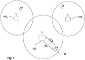
- the figure 1 illustrates the typical method of establishing such a quality indicator in a cellular network comprising, for purely illustrative purposes, three base stations NB 1 to NB 3 located respectively in three neighboring cells of this network.
- these base stations NB 2 and NB 3 emit signals likely to interfere with the communication, in the first cell, between the first transmitter device NB 1 and a mobile terminal M.
- the base station NB 1 transmits, in the first cell associated with it, a pilot signal SP, the characteristics of which are known to the mobile terminal M, on the downlink path. a radio communication channel so that the mobile terminal M can perform a measurement of the signal-to-noise ratio and SINR interference (compared with the known characteristics) and deduce the corresponding CQI indicator.
- the mobile terminal M can then transmit back, on the uplink of the radio communication channel to be evaluated, the CQI indicator to the base station NB 1 , so that the latter becomes aware of the transmission conditions on this channel, such as measured by the mobile terminal M, and can adapt the transmission rate to these conditions.
- This CQI indicator is in particular used by the base station NB 1 to predict the signal-to-noise ratio and SINR interference that will be experienced by the mobile terminal M in the future, and thus select the rate adapted to this signal-to-noise and interference ratio. SINR as predicted. In particular, the higher the predicted signal-to-noise and SINR interference ratio, the higher the selected rate, and vice versa.
- the rate selected by the base station is lower than the optimal rate, resulting in a loss of efficiency.
- the rate selected by the base station is then higher than the optimal rate, which may lead to an increase in the number of retransmissions of the data, and consequently an increase in the transmission delay.
- target user when such a user, called “target user”, is in a cell of a cellular network, it is possible that another user, called “interfering user”, also uses a sporadic service in a neighboring cell of this cell, which can create sporadic interference that is not necessarily reflected by the CQI indicator returned to the base station of the cell of the target user.
- the reassembled CQI indicator can then represent a signal-to-noise and SINR interference ratio which differs enormously from the signal-to-noise ratio and SINR interference actually experienced during the transmission of data.
- CQI mismatch This phenomenon is usually referred to as “CQI mismatch” and has been observed and measured in “CQI mismatch”.
- 3GPP LTE Downlink System Performance “, Farajidana et al., Global Telecommunications Conference, GLOBECOM 2009 , where the notion of sporadic interfering user is referred to as "partial loading”.
- this CQI mismatch phenomenon may also exist even when the interfering traffic in neighboring cells is not sporadic.
- the CQI mismatch can be caused by a "flash light” effect corresponding to the situation where a neighboring cell, although transmitting continuously (ie in "full loading"), saturates and strongly interferes sporadically with users. targets, because of beam-forming processes.
- the base station applies an offset to the CQI at the input of the link adaptation mechanism.
- the offset is controlled by a loop. If the base station receives a "NACK" message for a packet received by the mobile, the base station applies a decreased offset, and if it receives an "ACK” message, it applies an increased offset, the relation between the steps of increase and decrease of the offset depending on the "Block Error Rate” target ratio.
- the present invention therefore aims to solve the problem of CQI unconformity without causing the disadvantages of the prior art, particularly in terms of increased complexity, sub-optimization and loss of capacity.
- the total charge pilot signal comprises at least two total charge pilot symbols respectively modulating at least two subcarriers during at least a first symbol time dedicated to the transmission of symbols other than data symbols or a subcarrier during at least two first symbol times dedicated to the transmission of symbols other than data symbols
- the interfering pilot signal comprises a plurality of interfering pilot symbols among which at least two interfering pilot symbols respectively modulate, for each of the total charge pilot symbols, the subcarrier modulated by said total charge pilot symbol during the first symbol time wherein said subcarrier is modulated by said total charge pilot symbol.
- the interfering pilot signal does not modulate, during the at least one second symbol time during which the effective load pilot signal modulates at least one of said sub-carriers, this at least one modulated subcarrier by the actual load pilot signal.
- the effective load pilot signal comprises at least two effective load pilot symbols respectively modulating at least two subcarriers during at least a second symbol time dedicated to the transmission of data symbols or a subcarrier during at least two second symbol times dedicated to the transmission of data symbols, and the interfering pilot signal does not contain a modulating symbol, during the at least one second symbol time during which an effective charge pilot symbol modulates one of the sub-carriers , this subcarrier modulated by the effective charge pilot symbol.
- the interfering pilot signal comprises a plurality of pilot symbols arranged according to said pattern. predetermined and shifted in frequency relative to the pilot symbols of the reference pilot signal and the interfering pilot signal further comprises a plurality of complementary pilot symbols respectively modulating, during each first symbol time during which a total charge pilot symbol modulates a subcarrier , the set of subcarriers, among the plurality of orthogonal subcarriers, which are not modulated by any symbol.
- the determination of the quality indicator of the channel comprises the calculation of the minimum value, over a time window, of the function difference between the quality indicator of the channel in actual load and the indicator the channel quality indicator being determined to be the sum of the quality indicator of the full load channel and the said minimum value.
- the determination of the quality indicator of the channel comprises calculating the average value, over a time window, of the function difference between the quality indicator of the channel in actual load and the a full-load channel quality indicator, the channel quality indicator being determined as the sum of the quality indicator of the full load channel and said average value.
- the determination of the quality indicator comprises the calculation of the minimum value, the average value and the maximum value, over a time window, of the difference function between the quality indicator.
- the channel quality indicator is determined to be the sum of the quality indicator of the full load channel and a second variable, which second variable is chosen to be equal to this minimum value or this maximum value according to the comparison of the average value with a threshold.
- the method further comprises the transmitting the quality indicator of the full load channel and the quality indicator of the actual payload channel of the receiving device to the first transmitting device.
- the method further comprises transmitting the quality indicator of the receiving device to the first transmitting device.
- the transmitting devices of the first cell and neighboring cells are base stations and the receiving device is a mobile terminal.
- the invention further provides a computer program comprising instructions for executing the steps of the method of determining the quality indicator above, when said program is executed by a processing module of a transmitting device or of a receiver device.
- a computer program must be considered as a product within the framework of the protection which is sought by the present patent application.
- the invention further proposes a base station for establishing a quality indicator of a radio transmission channel with at least one mobile terminal, the base station being able to transmit data by means of a plurality of frequency-multiplexed orthogonal subcarriers and comprising an emitter module configured to transmit, to the mobile terminal, a reference pilot signal comprising a total charge pilot signal modulating at least one of said orthogonal subcarriers, during at least a first time symbol dedicated to the transmission of symbols other than data symbols, and an effective load pilot signal modulating at least one of said orthogonal subcarriers during at least a second symbol time dedicated to the transmission of data symbols, and the pilot signal of total charge and effective charge pilot signal being able to be used by the mobile terminal to respectively measure a total load quality indicator and an effective load quality indicator suitable for use in determining the quality indicator.
- this base station further comprises a receiving module able to receive the total load quality indicator and the effective load indicator measured by the mobile terminal and a processing module configured to determine the quality indicator using the actual load quality indicator and the total load quality indicator.
- the invention also proposes a mobile terminal for establishing a quality indicator of a radio transmission channel with a base station able to transmit data by means of a plurality of frequency-multiplexed orthogonal subcarriers and comprising a transmitter module adapted to receive, from said base station, a reference pilot signal comprising a total charge pilot signal modulating at least one of said orthogonal subcarriers, during at least a first symbol time dedicated to the transmission of other symbols data symbols, and an effective load pilot signal modulating at least one of said orthogonal subcarriers during at least a second symbol time dedicated to the transmission of data symbols, and a processing module configured to measure an indicator of full load quality by means of the pilot signal of total load and an effective load quality indicator using the effective load pilot signal, the actual load quality indicator and the total load quality indicator being suitable for use in determining the quality indicator.
- the processing module is further configured to determine the quality indicator by means of the actual load quality indicator and the total load quality indicator, the mobile terminal. further comprising a transmission module configured to transmit the quality indicator to the base station.
- the present invention proposes a cellular network in which a plurality of orthogonal frequency multiplexed subcarriers are used to transmit data, the cellular network comprising at least a first base station as described above, at least one second base station, located in a cell adjacent to the cell in which the first base station is located, the second base station transmitting a modulating interfering pilot signal, during at least a first symbol time during which the total charge pilot signal module at least one of said subcarriers, said at least one subcarrier modulated by the total charge pilot signal.
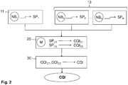
- FIG. 2 which illustrates the steps of a method of establishing a quality indicator CQI of the radio transmission channel according to the present invention.
- this method is implemented in a cellular network, similar to the cellular network illustrated in FIG. figure 1 , and using a set of L subcarriers f 0 , ..., f L-1 for data transmission, in particular on the downstream channel, according to the Orthogonal Frequency Division Multiplexing (OFDM) technique. in English).
- OFDM Orthogonal Frequency Division Multiplexing
- This cellular network comprises a certain number of cells among which is a first cell in which is located a first transmitter device NB 1 and a receiver device M communicating on a communication radio channel, for example in FDD mode (for Frequency Division Duplex ), that is to say with a first frequency dedicated to the downlink and a second frequency dedicated to the upstream channel.
- FDD mode Frequency Division Duplex
- the first transmitter device NB 1 is typically a base station, for example an "e-Node B" when the cellular network is of 3GPP LTE type, having a transmitting antenna capable of transmitting signals transmitted over the radio channel of communication.
- e-Node B when the cellular network is of 3GPP LTE type, having a transmitting antenna capable of transmitting signals transmitted over the radio channel of communication.
- the receiving device M is typically a mobile terminal such as a mobile phone, a smartphone or a laptop, having a receiving antenna capable of receiving signals transmitted over the communication radio channel.
- This first cell is surrounded by a number of neighboring cells.
- the figure 1 illustrates more particularly two neighboring cells of the first cell, to illustrate simply the invention principle, but the invention applies with any number of neighboring cells in which there is a transmitting device emitting a signal that can interfere with transmitted signals on the radio channel used in the first cell.
- a second transmitter device NB 2 whose transmitted signals are such as to interfere with the communication, in the first cell, between the first transmitter device NB 1 and the receiver device M.
- the first transmitting device NB 1 transmits (step 11) a reference pilot signal SP 1 in the first cell associated therewith.
- This pilot reference signal SP 1 comprises, on the one hand, a total charge pilot signal SP CT modulating at least one subcarrier of the set of orthogonal subcarriers during at least a first symbol time belonging to a first interval symbol time [t 11 ; t 12 ] dedicated to the transmission of symbols other than data symbols.
- This first symbol time interval [t 11 ; t 12 ] is not necessarily at the beginning of a data frame.
- total charge pilot signal SP CT The function of the total charge pilot signal SP CT is to enable the measurement of a first quality indicator, called “total load quality indicator” and designated by CQI CT , reflecting the total load reached when all the cells adjacent to the first cell transmit data.
- the total charge pilot signal SP CT comprises several pilot symbols of total charge, denoted by F1,..., Fi (with i ⁇ 2) thereafter.
- Each driver symbol of total charge Fi modulates, during a symbol time ⁇ 1, i belonging to the first interval [t 11 ; t 12 ], a subcarrier f i among the L orthogonal subcarriers used in the cellular network.
- pilot symbols of total charge Fi are notably arranged with each other so as not to modulate the same subcarrier during the same symbol time.
- the total charge pilot signal SP CT comprises only two total charge pilot symbols F1 and F2
- the reference pilot signal SP 1 further comprises an effective load pilot signal SP CE modulating at least one subcarrier of the set of orthogonal subcarriers during at least a second symbol time belonging to a second time interval. symbols [t 21 ; t 22 ] dedicated to the transmission of data symbols.
- this SP EC effective load pilot signal is to enable the measurement of a second quality indicator, the so-called “effective load indicator”, designated by CQI CE , reflecting the actual load due to the transmission of data in neighboring cells.
- the effective load pilot signal SP CE comprises several effective load pilot symbols, designated A1,..., Aj (with j ⁇ 2) thereafter.
- Each effective charging pilot symbol Aj modulates, during a symbol time ⁇ 2, j belonging to the second symbol time interval [t 21 ; t 22 ], a subcarrier f j among the L orthogonal subcarriers used in the cellular network. .
- pilot symbols of effective charge Aj are arranged between them so as not to modulate the same sub-carrier during the same symbol time, in order to allow the deduction of the signal-to-noise ratio and SINR interference.
- THIS during the second symbol time interval [t 21 ; t 22 ] with techniques known to those skilled in the art, it being understood that the greater the number of pilot symbols of effective charge Aj is important, the more effective is the measurement of this SINR ratio CE .
- a transmitting device emits an interfering pilot signal (step 13). So, in the network shown in the figure 1 , the transmitting device NB 2 emits an interfering pilot signal SP 2 into the second cell and the transmitting device NB 3 emits an interfering pilot signal SP 3 into the third cell.
- Each of the interfering pilot signal (s) modulates the same subcarrier (s) as that modulated by the total charge pilot signal SP CT of the reference pilot signal SP emitted by the device, during the (or) the same symbol time during which this modulation takes place by the total charge pilot signal SP CT .
- each interfering pilot signal SP 2, SP 3, ... includes interfering symbols placed at the same time-frequency position (f i; ⁇ 1 , i ) that the total load pilot symbol (s) Fi of the total load pilot signal SP CT .
- the interfering pilot signal SP 2 comprises, for each total charge pilot symbol Fi belonging to the total charge pilot signal SP CT , an interfering pilot symbol Fi 'modulating the same subcarrier f i as the symbol Fi, during the same symbol time ⁇ 1, i .
- the interfering pilot signal of neighboring cells is advantageously arranged so as not to contain an interfering symbol modulating the same subcarrier, during the same symbol time, as an effective charging pilot symbol Aj of the effective charge pilot signal. SP CE .
- each interfering pilot signal SP 2 , SP 3 , ... does not include an interfering pilot symbol placed at the same position (f j ; ⁇ 2 , j ) an effective load pilot symbol Aj of the effective load pilot signal SP CE .
- the measurement device (step 20) is then measured by the receiver device M located in the first cell of the CQI CT total load quality indicator and the CQI CE effective load quality indicator.
- the total load quality indicator CQI CT is measured by means of the total load pilot symbols Fi of the total load pilot signal SP CT , by measuring the signal-to-noise and interference ratio SINR CT associated with all the total charge drivers symbol Fi of this pilot signal SP CT and deriving the quality indicator corresponding to this SINR CT signal-to-noise and interference ratio, similar to what is done for a traditional CQI channel quality indicator.
- the quality indicator of the CQI CE effective load channel is measured by the effective load pilot symbols Aj of the effective load pilot signal SP CE , by measuring the signal-to-noise and interference ratio SINR CE associated with the all of these effective load pilot symbols Aj of this SP signal CE and deducing the quality indicator corresponding to this SINR CE signal-to-noise and interference ratio, similar to what is done for a traditional CQI channel quality indicator.
- the CQI quality indicator of the radio transmission channel is then determined (step 30) on the basis of these quality indicators CQI CT and CQI CE .
- This step 30 of determining the CQI quality indicator, based on a CQI CT total load quality indicator and an CQI CE effective load quality indicator, can be carried out according to various embodiments illustrated on FIGS. FIGS. 3A to 3E .
- the step 20 of measuring these quality indicators are obtained by performing the step 20 of measuring these quality indicators regularly, for example with a multiple period of the frame of the system.
- the step of measuring the CQI CT and CQI CE indicators can be performed every k milliseconds, where k is an integer greater than 1.
- the curve of the CQI CT full load quality indicator directly reflects the changing radio conditions affecting the receiver device M, regardless of the activity on the network.
- the curve of the CQI CE effective load indicator indirectly reflects information on the impact of the activity on the network on the evolution of the quality indicator of the CQI radio communication channel, independently radio conditions affecting the receiver device M.
- the two decorrelated information provided by these CQI CT and CQI CE indicators can then be used to obtain a more accurate CQI channel quality indicator than the indicators usually obtained in the state of the art.
- the maximum load activity observed on the cellular network is mainly considered, which offers a conservative, simple and effective solution for calculating this CQI indicator. .
- Low ⁇ CQI THIS - CQI CT not Minimum Low ⁇ CQI THIS - CQI CT not - 1 , CQI THIS not - CQI CT not .
- the quality indicator of the radio transmission channel CQI 1 is then determined, at a given instant n, as being the sum of the quality indicator of the total loaded channel CQI CT and of this value. minimal.
- CQI 1 (n) CQI CT (n) + Min [ ⁇ (CQI CE -CQI CT )] (n)
- This quality indicator of the radio transmission channel CQI 1 can then be used by the transmitter device NB 1 to adapt the transmission rate on the downstream channel, according to techniques known to those skilled in the art which will not be detailed here.
- the figure 3B illustrates the time evolution of the quality indicator of the CQI radio transmission channel 1 obtained with this first embodiment of this determination step 30.
- this indicator CQI 1 remains permanently between the two curves of the CQI CE and CQI CT indicators on the window in question.
- This CQI 1 indicator takes into account both the instantaneous evolution of radio conditions (through its CQI CT component) and the average evolution of network activity peaks (through its Min [ ⁇ (CQI component) CE -CQI CT )]).
- step 30 of determining the quality indicator CQI the average of the difference between a maximum charge activity and an effective charging activity as observed on the cellular network is mainly considered. which offers an opportunistic and simple solution for calculating this CQI indicator.
- the average value ⁇ (CQI CE -CQI CT )] of the difference function ⁇ (CQI CE -CQI CT ) is calculated between the effective load quality indicator CQI CE and the quality indicator. total load CQI CT , on a sliding time window T as defined above.
- Moy ⁇ CQI THIS - CQI CT not Average Moy ⁇ CQI THIS - CQI CT not - 1 , CQI THIS not - CQI CT not .
- the quality indicator of the CQI channel 2 is then determined, at a given instant n, as being the sum of the quality indicator of the total loaded channel CQI CT and of this average value.
- CQI 2 (n) CQI CT (n) + Moy [ ⁇ (CQI CE -CQI CT )]
- This quality indicator of the CQI radio transmission channel 2 can then be used by the transmitter device NB 1 to adapt the transmission rate on the downstream channel.
- the figure 3C illustrates the temporal evolution of the quality indicator of the CQI channel 2 obtained with this second embodiment of this determination step 30.
- the curve of this indicator CQI 2 may at times exceed the curve of the quality indicator CQI CE effective load on the window, which amounts to overestimate the quality of the radio channel at these times.
- This CQI 2 indicator takes into account both the instantaneous evolution of radio conditions (through its CQI CT component) and the average evolution of activity on the network (through its Moy [ ⁇ (CQI component) CE -CQI CT )]).
- step 30 of determining the quality indicator CQI the difference between a maximum charge activity and an effective charging activity as observed on the cellular network is statistically considered. which offers a more efficient solution with increased computational complexity.
- the minimum value Min [ ⁇ (CQI CE -CQI CT )], the average value Moy [ ⁇ (CQI CE -CQI CT )] and the maximum value Max [ ⁇ (CQI CE -CQI CT )] are calculated. of the difference function ⁇ (CQI CE -CQI CT ) between the effective load quality indicator CQI CE and the total load quality indicator CQI CT , over a sliding time window T as defined above.
- the 3D figure illustrates the time evolution of these three values obtained with this third embodiment of this determination step.
- the quality indicator CQI 4 of the channel then takes, at a given instant n, the value of the quality indicator CQ 1 or the value of the quality indicator CQ 3 , and this according to the comparison of the quality indicator CQ 2 with a parameterizable threshold K, which can be for example at a given percentage of the difference between the maximum value Max [ ⁇ (CQI CE -CQI CT )] and the value minimum Min [ ⁇ (CQI CE -CQI CT )] at this instant n.
- a parameterizable threshold K which can be for example at a given percentage of the difference between the maximum value Max [ ⁇ (CQI CE -CQI CT )] and the value minimum Min [ ⁇ (CQI CE -CQI CT )] at this instant n.
- the figure 3E illustrates the time evolution of the quality indicator of the CQI radio transmission channel 4 obtained with this third embodiment of this determination step 30.
- the quality indicator CQI 4 goes into a first state where it corresponds to the quality indicator CQI 1 , in a situation 1 corresponding to moments where the mean value Moy [ ⁇ (CQI CE -CQI CT )] exceeds the threshold K, while this quality indicator CQI 4 goes to a second more conservative state where it corresponds to the quality indicator CQI 3 , in a situation 2 corresponding to times when the mean value Moy [ ⁇ (CQI CE -CQI CT )] is less than or equal to this threshold K.
- This CQI 4 indicator therefore takes into account the instantaneous evolution of radio conditions through its CQI CT component, as well as the probability of having a high or low activity on the network compared to a reference activity threshold, the through a second component which can be either the minimum value Min [ ⁇ (CQI CE -CQI CT )] or the maximum value Max [ ⁇ (CQI CE -CQI CT )].
- the determination of the quality indicator CQI can be performed at the receiver device M or at the transmitter device NB 1 , according to the constraints and the context of application of the present invention.
- the Figure 4A thus illustrates the steps of a method for establishing the quality indicator CQI according to a first embodiment of the present invention where this determination is made at the receiver device M.
- the quality indicator CQI of the radio transmission channel is deduced by the receiver device M from the quality indicators CQI CT and CQI CE (step 31), then transmitted to the first transmitter device NB 1 (step 33), so that the latter can adapt the transmission rate according to this CQI indicator.
- This first embodiment is advantageous in that it is transparent for the transmitter device NB 1 , since the latter receives a CQI channel quality indicator similar to the indicators usually used in the state of the art, and can therefore be used. with traditional base stations without modifying the link adaptation process of the latter.
- the Figure 4B illustrates the cellular network in which the method according to the first embodiment of the present invention is implemented.
- the receiver device M comprises a receiver module (a radio antenna for example) adapted to receive the reference pilot signal SP 1 sent by the base station NB 1 , a processing module (typically comprising a processor associated with a RAM) configured to implement the steps of measuring the CQI CT and the CQI CE actual load quality indicators and of determining the CQI channel quality indicator from these CQI CT and CQI CE indicators, as described above, and a transmitter module (a radio antenna for example) for transmitting the quality indicator of the CQI channel to the base station NB 1 .
- a receiver module a radio antenna for example
- a processing module typically comprising a processor associated with a RAM
- the base station NB 1 comprises a transmitter module (a radio antenna typically) configured to transmit, to the mobile terminal M, the reference pilot signal SP 1 and a receiver module (a radio antenna typically) adapted to receive in return the quality indicator of the CQI channel calculated and transmitted by the mobile terminal M.
- the other base stations NB 2 and NB 3 for their part, each comprise a transmitter module (A radio antenna typically) configured to transmit, in their respective cells, an interfering pilot signal SP 2 as described above.
- the Figure 5A illustrates the steps of a method for establishing the quality indicator CQI according to a second embodiment of the present invention where this determination is made, this time, at the transmitter device NB 1 .
- the quality indicators CQI CT and CQI CE are first transmitted (step 35) by the receiving device M to the sending device NB 1 , before this sending device NB 1 does the deduction of the quality indicator CQI from these quality indicators CQI CT and CQI CE (step 37).
- This second embodiment is particularly advantageous in that it makes it possible to limit the computing resources required at the level of the receiver device M, since the calculation of the quality indicator CQI is carried out this time at the transmitter device NB 1 which usually has greater computing capabilities (this is particularly the case of a network with base stations communicating with mobile-type mobile terminals).
- this embodiment has the advantage of being more scalable insofar as it is easier for the operators to update the sending devices belonging to their networks than the receiving devices, which are much more numerous and inhomogeneous. .
- the Figure 5B illustrates the cellular network in which the method according to the second embodiment of the present invention is implemented.
- the base station NB 1 comprises a transmitter module (a radio antenna typically) configured to transmit, to the mobile terminal M, the pilot reference signal SP 1 and a receiver module (a radio antenna typically) able to receive in return the quality indicators CQI CT and CQI CE calculated and transmitted by the mobile terminal M.
- the base station NB 1 further comprises a processing module (typically comprising a processor associated with a random access memory) configured to implement the step of determining the quality indicator of the CQI channel from these CQI CT and CQI CE indicators.
- the other base stations NB 2 and NB 3 each comprise a transmitter module (a radio antenna typically) configured to transmit, in their respective cells, an interfering pilot signal SP 2 as described above.
- the receiver device M comprises, meanwhile, a receiver module (a radio antenna for example) adapted to receive the reference pilot signal SP 1 transmitted by the base station NB 1 , a processing module (typically comprising a processor associated with a random access memory) configured to implement the step of measuring the quality indicators in full load CQI CT and in effective load CQI CE as described above, and a transmitter module (for example a radio antenna) for transmitting these quality indicators CQI CT and CQI CE to the base station NB 1 .
- a receiver module a radio antenna for example
- a processing module typically comprising a processor associated with a random access memory
- a transmitter module for example a radio antenna
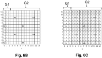
- FIGS. 6A to 6D illustrate a reference pilot signal SP 1 , as emitted by a first transmitting device located in a first cell of a cellular network, and an interfering pilot signal SP 2 , as emitted by a second transmitter device located in a neighboring cell of the first cell in the cellular network, represented in a same two-dimensional block in time and frequency.
- Figure 6A illustrates a reference pilot signal SP 1 emitted by the first transmitter device NB 1 located in the first cell of the cellular network illustrated in FIG. figure 1 .
- This pilot reference signal SP 1 comprises in particular two pilot symbols of total charge F 1 and F 2 , as well as six pilot symbols of effective charge A 1 to A 6 , in this non-limiting example.
- the total charge pilot symbols F 1 , F 2 are located in a zone G 1 of the two-dimensional block which is dedicated to the transmission of symbols other than data symbols themselves, such as for example signaling or control symbols. Thus, these total load pilot symbols F 1 , F 2 can not be interfered with by data symbols transmitted in other neighboring cells.
- This zone G1 here typically corresponds to the preamble reserved for control symbols.
- this zone G1 corresponds to the preamble reserved for the so-called PDCCH symbols transmitted during a first interval [t 11 , t 12 ] covering the first 1, 2 or 3 symbol times (according to the configuration of the PDCCH ) frames transmitted by the sending devices NB 1 , NB 2 , etc.
- pilot symbols of effective charge A 1 to A 6 are placed in a zone G 2 of the two-dimensional block in time and frequency which is dedicated to the transmission of data symbols themselves.
- these effective load pilot symbols can only be interfered with by data symbols transmitted in other neighboring cells.
- This zone G2 here typically corresponds to the resource block, or "payload" field, reserved for the data symbols during the last symbol times of the frames transmitted by the sending devices NB 1 , NB 2 , etc.
- the Figure 6B illustrates the two-dimensional block in time and frequency when the zone G1 is fully loaded and the resource block G2 is empty.
- the G1 area of this block is completely filled with PDCCH symbols (designated "c"), with the exception of the pilot symbols of total charge F 1 and F 2 belonging to the total charge pilot signal SP CT .
- zone G2 only the effective load pilot symbols A1 to A6 appear.
- the Figure 6C illustrates the two-dimensional block in time and frequency when the area G1 is fully loaded and the resource block G2 is also fully loaded.
- the area G1 of this two-dimensional block is completely filled with PDCCH symbols (designated "c"), with the exception of the full load pilot symbols F1 and F2, and the resource block G2 is completely filled with symbols of data (designated "d"), with the exception of the effective load pilot symbols A1 to A6 belonging to the effective load pilot signal SP CE .
- the Figure 6D illustrates an interfering pilot signal SP 2 emitted by the second transmitter device NB 2 located in the second cell of the cellular network illustrated in FIG. figure 1 .
- This interfering pilot signal SP 2 comprises two interfering pilot symbols F'1, F'2, situated in the area G1 of the two-dimensional block in time and in frequency, as well as three other interfering symbols B1 to B3 situated in the area G2 of the two-dimensional block. in time and frequency.
- the interfering pilot symbols F'1, F'2 are in particular placed in the same position, in this two-dimensional block, as the total load pilot symbols F1, F2 of the Figure 6A of the reference pilot signal SP 1 emitted by the transmitter device NB 1 , in order to interfere with this pilot reference signal.
- interfering pilot symbols F'1 and F'2 can be used to enable the transmitter device NB 2 to measure a total quality of charge indicator CQI CT2 for the second cell, similar to what is achieved by the transmitter device NB 1 , in which case these interfering pilot symbols may then correspond to total charge pilot symbols belonging to a total charge pilot signal SP CT2 , used in the second cell, provided that these symbols F'1, F'2 are known. a receiver device present in the second cell to enable the determination of this CQI CT2 total load quality indicator by this receiver device.
- the other three interfering symbols B1 to B3 are placed, on the contrary, at positions of the two-dimensional block that do not correspond to the positions of the effective load pilot symbols A1 to A6 of the reference pilot signal SP 1 .
- the positions of these symbols A1 to A6 are recalled by shaded boxes on the Figure 6D .
- the positions of these pilot symbols of effective charge A1 to A6 are kept free of any interfering pilot symbol, in the interfering pilot signals transmitted in the neighboring cells, so that only the data symbols transmitted in the cells neighbors can interfere with these pilot symbols of effective charge A1 to A6 in the cell of interest, and therefore measuring an effective CQI CE load quality indicator in the cell of interest reflecting as accurately as possible the actual load in terms of data transmitted in neighboring cells.
- interfering symbols B1 to B3 can also be used, within the second cell, to enable the transmitter device NB 2 to measure an effective quality of charge indicator CQI CE2 for the second cell, similar to what is done by the transmitting device NB 1 , in which case these interfering symbols can correspond to actual load pilot symbols belonging to an effective load pilot signal SP CE2 , from the point of view of the second cell, provided that these symbols B1 to B3 are known.
- a receiver device present in the second cell, in order to allow the determination of this CQI CE2 effective load quality indicator by this receiver device.
- the transmitter devices NB j of neighboring cells transmit pilot signals having the same set of pilot symbols arranged in the same pattern, in a two-dimensional block in time and in frequency, but shifted in frequency from one pilot signal to another.
- Figure 7A again illustrates the reference pilot signal SP 1 emitted by the first transmitter device NB 1 located in the first cell of the cellular network illustrated in FIG. figure 1 as already illustrated in Figure 6A .
- the pilot symbols F1, F2 and A belonging to this signal SP 1 are arranged in a predetermined pattern in the two-dimensional block in time and in frequency.
- the Figure 7B illustrates an interfering pilot signal SP 2 emitted by the second transmitter device NB 2 located in the second cell of the cellular network illustrated in FIG. figure 1 according to this other embodiment.
- the pilot symbols F1, F2 and A have an arrangement respecting the same pattern, in the two-dimensional block, as the pilot symbols of the first pilot signal SP 1 , with a frequency shift of a sub-frequency. carrier.
- pilot symbols of effective charge A modulate, during the fifth symbol time of the two-dimensional block, the fifth and eleventh orthogonal subcarriers f 4 and f 10 in the pilot signal SP 2, while pilot symbols of effective charge A modulate during the same fifth symbol time of the two-dimensional block, the fourth and tenth orthogonal subcarriers f 3 and f 9 in the pilot signal SP 1 .
- This pattern of pilot symbols can thus be included in each pilot signal SP j emitted by each transmitter device NB j from a group of neighboring cells, shifting each time the pilot symbols of a sub-carrier.
- Such a pattern of pilot signals may in particular correspond to the reference signals transmitted in a LTE-type cellular network (for L ong T erm E volution).
- pilot symbols are added to the pilot signals of total load Fi in each pilot signal SP j of the neighboring cell group.
- additional pilot symbols may be stuffing symbols, non-zero, of any type.
- these complementary pilot symbols ds modulate, during the symbol time (s) where a total charge pilot symbol Fi modulates one of the orthogonal subcarriers, all the other subcarriers, among the L sub-carriers, orthogonal carriers, which are not modulated by any symbol.
- each of the N orthogonal subcarriers is modulated by a symbol.
- each total charge pilot symbol Fi is then interfered by all the pilot signals of the neighboring cells of this cell, which makes it possible to obtain a reliable CQI CT total load quality indicator.
- the Figure 7C illustrates an interfering pilot signal SP 2 comprising such complementary pilot symbols.
- This interfering pilot signal SP 2 furthermore comprises complementary pilot symbols ds modulating the other subcarriers f 0 , f 2 to f 6 and f 8 to f 11 during the same first symbol time.
- This filling scheme for a given symbol time of the zone G1 of the dimensional block, can be repeated for all the pilot signals SP 1 , SP 2 , ... in order to guarantee obtaining a quality indicator of Total CT CQI load reliable.
- pilot symbols of total charge are modulated during distinct first symbol times.
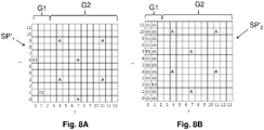
- the figure 8A illustrates a reference pilot signal SP 1 'according to this other particular embodiment, as emitted by the first transmitter device NB 1 located in the first cell of the cellular network illustrated in FIG. figure 1 .
- the Figure 8B illustrates an interfering pilot signal SP 2 'adapted to such a reference pilot signal SP 1 '.
- the interfering pilot signal SP 2 in addition to the total charge pilot symbol F1 modulating the eighth subcarrier f 7 , the interfering pilot signal SP 2 'comprises complementary pilot symbols modulating the other subcarriers f 0 to f 6 and f 8 to f 11 during the same first symbol time.
- the interfering pilot signal SP 2 in addition to the total charge pilot symbol F2 modulating the third subcarrier f 2 , the interfering pilot signal SP 2 'comprises complementary pilot symbols modulating the other subcarriers f 0 to f 1 and f 3 to f 11 during the same second symbol time.
- the present invention further provides a computer program comprising code instructions for implementing the method of establishing the CQI channel quality indicator described above, and in particular the step of determining this indicator of CQI channel quality from the CQI CT and CQI CE full load channel quality indicators, when this program is executed by a transmitter device processing module, as is the case in the described embodiment to the Figure 5B , or of a receiver device, as is the case in the embodiment described in Figure 4B .
- Such a program can use any programming language, and be in the form of source code, object code, or intermediate code between source code and object code, such as in a partially compiled form, or in n ' any other desirable form.
- the present invention also provides a data carrier readable by a data processor, and including code instructions of one of the programs mentioned above.
- This information carrier may be any entity or device capable of storing the aforementioned program.
- the medium may comprise storage means, such as a ROM, for example a CD-ROM or a microelectronic circuit ROM, or a recording medium magnetic, for example a diskette or a hard disk.
- This information carrier may also include FLASH type memory, for storing the program and recording information received by a client module, and RAM type memory for the backup of temporary data such as server lists and themes. associates.
- this information medium may be a transmissible medium such as an electrical or optical signal, which may be conveyed via an electrical or optical cable, by radio or by other means.
- the programs according to the invention may in particular be downloaded on an Internet-type network.
- this invention is particularly applicable to OFDM cellular networks in FDD mode, as defined in the 3GPP-LTE, LTE-A, IEEE WiMAX Mobile (IEEE 802.16) or WiFI (IEEE 802.11) standards.
Landscapes
- Engineering & Computer Science (AREA)
- Signal Processing (AREA)
- Computer Networks & Wireless Communication (AREA)
- Mobile Radio Communication Systems (AREA)
Description
Le domaine de l'invention est celui des réseaux de télécommunications cellulaires sans fil, et en particulier les réseaux cellulaires utilisant le multiplexage par répartition en fréquences orthogonales (OFDM en anglais) pour la transmission de données vers des terminaux mobiles.The field of the invention is that of wireless cellular telecommunications networks, and in particular cellular networks using orthogonal frequency division multiplexing (OFDM) for the transmission of data to mobile terminals.
Dans ce type de réseaux cellulaires, le terminal mobile d'un usager mesure habituellement la qualité de son canal de communication radio grâce à des pilotes envoyés par la station de base sur la voie descendante, avant de remonter sur la voie montante un indicateur de qualité du canal, appelé « Channel Quality Indicator » (CQI) en anglais, à cette station de base.In this type of cellular network, the mobile terminal of a user usually measures the quality of his radio communication channel with pilots sent by the base station on the downstream path, before ascending the uplink a quality indicator channel, called the Channel Quality Indicator (CQI) in English, at this base station.
Un tel indicateur CQI est représentatif du rapport signal sur bruit et interférence (SINR pour Signal To Interference and Noise Ratio en anglais) perçu par le terminal mobile au moment de sa mesure.Such CQI is representative of the signal to noise and interference ratio (SINR for S ignal To I nterference and N oise R atio English) received by the mobile terminal at the time of measurement.
La
Dans les cellules associées aux stations de base NB2 et NB3, voisines de la première cellule, ces stations de base NB2 et NB3 émettent des signaux de nature à interférer la communication, dans la première cellule, entre le premier dispositif émetteur NB1 et un terminal mobile M.In the cells associated with base stations NB 2 and NB 3 , adjacent to the first cell, these base stations NB 2 and NB 3 emit signals likely to interfere with the communication, in the first cell, between the first transmitter device NB 1 and a mobile terminal M.
Afin de tenir compte de ce phénomène d'interférence intercellulaire, la station de base NB1 émet, dans la première cellule qui lui est associée, un signal pilote SP, dont les caractéristiques sont connues du terminal mobile M, sur la voie descendante d'un canal de communication radio afin que ce terminal mobile M puisse effectuer une mesure du rapport signal sur bruit et interférence SINR (par comparaison avec les caractéristiques connues) et en déduire l'indicateur CQI correspondant.In order to take account of this phenomenon of intercell interference, the base station NB 1 transmits, in the first cell associated with it, a pilot signal SP, the characteristics of which are known to the mobile terminal M, on the downlink path. a radio communication channel so that the mobile terminal M can perform a measurement of the signal-to-noise ratio and SINR interference (compared with the known characteristics) and deduce the corresponding CQI indicator.
Le terminal mobile M peut alors transmettre en retour, sur la voie montante du canal de communication radio à évaluer, l'indicateur CQI à la station de base NB1, afin que cette dernière prenne connaissance des conditions de transmission sur ce canal, telles que mesurées par le terminal mobile M, et puisse adapter le débit de transmission à ces conditions.The mobile terminal M can then transmit back, on the uplink of the radio communication channel to be evaluated, the CQI indicator to the base station NB 1 , so that the latter becomes aware of the transmission conditions on this channel, such as measured by the mobile terminal M, and can adapt the transmission rate to these conditions.
Cet indicateur CQI est en particulier utilisé par la station de base NB1 pour prédire le rapport signal sur bruit et interférence SINR qui sera subi par le terminal mobile M dans le futur, et ainsi sélectionner le débit adapté à ce rapport signal sur bruit et interférence SINR tel que prédit. En particulier, plus le rapport signal sur bruit et interférence SINR prédit est élevé, et plus le débit sélectionné est élevé, et vice versa.This CQI indicator is in particular used by the base station NB 1 to predict the signal-to-noise ratio and SINR interference that will be experienced by the mobile terminal M in the future, and thus select the rate adapted to this signal-to-noise and interference ratio. SINR as predicted. In particular, the higher the predicted signal-to-noise and SINR interference ratio, the higher the selected rate, and vice versa.
L'efficacité de ce type de mécanisme, appelé « adaptation de lien » (« link adaptation » ou « Adaptive Modulation and Coding » en anglais) dépend de la pertinence de l'indicateur CQI remonté à la station de base.The effectiveness of this type of mechanism, called "link adaptation" or "Adaptive Modulation and Coding", depends on the relevance of the CQI indicator returned to the base station.
Si cet indicateur CQI est sous-estimé, le débit sélectionné par la station de base est plus faible que le débit optimal, ce qui engendre une perte d'efficacité.If this CQI is underestimated, the rate selected by the base station is lower than the optimal rate, resulting in a loss of efficiency.
Si par contre cet indicateur CQI est surestimé, le débit sélectionné par la station de base est alors plus élevé que le débit optimal, ce qui peut engendrer une augmentation du nombre de retransmissions des données, et par conséquent une augmentation du délai de transmission.If, on the other hand, this CQI indicator is overestimated, the rate selected by the base station is then higher than the optimal rate, which may lead to an increase in the number of retransmissions of the data, and consequently an increase in the transmission delay.
Ceci est particulièrement problématique dans le cas d'un usager utilisant un service sporadique (c'est-à-dire dans lequel des paquets de données sont envoyés de manière sporadique) et en temps réel (donc avec une forte contrainte de délai), comme c'est le cas de services concernant la transmission de voix, le streaming ou les jeux vidéos en réseau.This is particularly problematic in the case of a user using a sporadic service (ie in which data packets are sent sporadically) and in real time (so with a strong delay constraint), such as this is the case for services relating to voice transmission, streaming or network video games.
En effet, lorsqu'un tel usager, dit « usager cible », se trouve dans une cellule d'un réseau cellulaire, il se peut qu'un autre usager, dit « usager interférent », utilise également un service sporadique dans une cellule voisine de cette cellule, ce qui peut créer une interférence sporadique qui n'est pas forcément reflétée par l'indicateur CQI remonté à la station de base de la cellule de l'usager cible.Indeed, when such a user, called "target user", is in a cell of a cellular network, it is possible that another user, called "interfering user", also uses a sporadic service in a neighboring cell of this cell, which can create sporadic interference that is not necessarily reflected by the CQI indicator returned to the base station of the cell of the target user.
En fait, dans une telle situation d'interférence sporadique, l'indicateur CQI remonté peut alors représenter un rapport signal sur bruit et interférence SINR qui diffère énormément du rapport signal sur bruit et interférence SINR effectivement subi lors de la transmission de données.In fact, in such a situation of sporadic interference, the reassembled CQI indicator can then represent a signal-to-noise and SINR interference ratio which differs enormously from the signal-to-noise ratio and SINR interference actually experienced during the transmission of data.
Deux cas de figures peuvent alors se produire :
- dans un premier cas, l'indicateur CQI remonté se révèle trop optimiste : si au moment de la mesure du CQI par le terminal de l'usager cible, les cellules interférentes sont inactives, et qu'au moment de la transmission de données, elles deviennent actives, l'indicateur CQI remonté sera trop élevé par rapport à la situation réelle, et donc le débit utilisé par la station de base sera trop élevé, ce qui engendre un grand nombre de retransmissions dégradant fortement la qualité du service temps réel de l'usager cible.
- dans un deuxième cas, l'indicateur CQI remonté se révèle trop pessimiste : si au moment où le terminal de l'usager cible effectue sa mesure de CQI, les cellules interférentes sont actives et qu'au moment de la transmission de données elles deviennent inactives, l'indicateur CQI remonté sera alors trop faible, et le débit sélectionné par la station de base sera plus faible que le débit optimal. La capacité de la cellule (en termes de nombre d'usagers supportés) sera alors amoindrie.
- in the first case, the CQI indicator is too optimistic: if at the time of the CQI measurement by the terminal of the target user, the interfering cells are inactive, and at the time of the transmission of data, they become active, the CQI raised indicator will be too high compared to the actual situation, and therefore the bit rate used by the base station will be too high, which generates a large number of retransmissions greatly degrading the quality of the real-time service of the target user.
- in a second case, the reasserted CQI indicator is too pessimistic: if at the moment when the terminal of the target user performs its CQI measurement, the interfering cells are active and at the time of data transmission they become inactive , the raised CQI indicator will then be too weak, and the rate selected by the base station will be lower than the optimal rate. The capacity of the cell (in terms of the number of users supported) will then be reduced.
Ce phénomène est habituellement désigné sous le terme de « discordance de CQI » (« CQI mismatch » en anglais) et a été observé et mesuré dans "
On remarquera que ce phénomène de discordance de CQI peut également exister même lorsque le trafic interférent dans les cellules voisines n'est pas sporadique. Par exemple, la discordance de CQI peut être causée par un effet « flash light » correspondant à la situation où une cellule voisine, bien que transmettant de manière continue (i.e. en « full loading »), sature et interfère fortement de manière sporadique les usagers cibles, du fait de processus de focalisation de faisceau (« beam forming »).It will be noted that this CQI mismatch phenomenon may also exist even when the interfering traffic in neighboring cells is not sporadic. For example, the CQI mismatch can be caused by a "flash light" effect corresponding to the situation where a neighboring cell, although transmitting continuously (ie in "full loading"), saturates and strongly interferes sporadically with users. targets, because of beam-forming processes.
Comme la discordance de CQI impacte principalement les usagers cibles ayant un ratio interférence sur bruit non négligeable, les usagers en bordure de cellule sont les plus affectés par cette discordance de CQI.Since the CQI mismatch primarily affects target users with a significant noise-to-noise ratio, cell-side users are the most affected by this CQI mismatch.
Un certain nombre de techniques ont été développées afin d'essayer de résoudre ce problème de discordance de CQI :
- La station de base peut appliquer une marge fixe à l'indicateur CQI reporté par le terminal mobile. La station de base utilise donc un CQI pessimiste en entrée de son mécanisme d'adaptation de lien, pour être robuste aux variations d'interférence. Cette technique présente l'inconvénient d'appliquer la même marge à tous les mobiles, quelle que soit leur caractéristique, et se trouve donc être sous-optimale.
- La station de base peut moyenner plusieurs indicateurs CQI reportés par le terminal mobile. La station de base utilise alors un indicateur CQI moyenné en entrée de son mécanisme d'adaptation de lien pour être robuste aux variations d'interférence. Cette technique reste sous-optimale, surtout dans la mesure où le problème d'optimisation de la fenêtre de moyennage, par cellule, est difficile à résoudre.
- Il a été envisagé de recourir à des procédés d'annulation d'interférence, qui se révèlent cependant être extrêmement complexes car, lors de la réception de données, le terminal mobile doit être capable de démoduler conjointement le signal utile et le signal interférent pour supprimer le signal interférent. Cette complexité est proportionnelle au nombre d'éléments interférents à supprimer.
- On peut également utiliser une technique où toutes les cellules transmettent tout le temps, et éventuellement des bits de padding, afin de créer une interférence stable. Une telle technique est sous-optimale, car de l'énergie est dépensée inutilement pour transmettre des bits (padding) sans signification (padding), ce qui est d'autant plus sous-optimal lorsque le réseau est faiblement chargé.
- Il est possible de recourir des techniques de coordination d'interférence entre cellules (ICIC), qui se révèlent cependant également très complexes en termes de planification et n'empêchent pas la persistance de zones de recouvrement entrainant une réduction de la capacité de la cellule.
- Il a été également envisagé de placer un atténuateur dans le terminal mobile, juste derrière l'antenne de réception et avant la chaîne de traitement de signal analogique-numérique. Cet atténuateur atténue le signal reçu avant que le bruit dû à la conversion analogique numérique soit ajouté. Avec un bon atténuateur, l'interférence devient négligeable devant le bruit, et le système devient moins sensible aux variations d'interférence.
- The base station may apply a fixed margin to the CQI flag reported by the mobile terminal. The base station therefore uses a pessimistic CQI input of its link adaptation mechanism, to be robust to interference variations. This technique has the disadvantage of applying the same margin to all mobiles, regardless of their characteristics, and therefore is suboptimal.
- The base station can average several CQI indicators reported by the mobile terminal. The base station then uses an averaged CQI indicator input of its link adaptation mechanism to be robust to interference variations. This technique remains sub-optimal, especially since the optimization problem of the averaging window, per cell, is difficult to solve.
- It has been envisaged to use interference cancellation methods, which however prove to be extremely complex because, when receiving data, the mobile terminal must be able to jointly demodulate the wanted signal and the interfering signal to suppress the interfering signal. This complexity is proportional to the number of interfering elements to be deleted.
- One can also use a technique where all cells transmit all the time, and possibly padding bits, to create a stable interference. Such a technique is suboptimal, because energy is spent unnecessarily to transmit padding (padding), which is all the more suboptimal when the network is weakly loaded.
- It is possible to use inter-cell interference coordination (ICIC) techniques, which, however, are also very complex in terms of planning and do not prevent the persistence of overlapping areas that reduce the capacity of the cell.
- It has also been envisaged to place an attenuator in the mobile terminal just behind the receiving antenna and before the analog-digital signal processing chain. This attenuator attenuates the received signal before the noise due to the digital analog conversion is added. With a good attenuator, the interference becomes negligible in front of the noise, and the system becomes less sensitive to interference variations.
Cette solution présente cependant l'inconvénient d'entraîner une atténuation du signal utile reçu par le terminal mobile, qui perd donc systématiquement en capacité et en couverture. En outre, la performance de l'atténuateur dépend des constructeurs de mobile et ne peut donc être garantie.
- On peut enfin utiliser une technique d'adaptation de lien telle que décrite dans l'article "
Performance aspects of LTE uplink with variable load and bursty data traffic," Rosa C. et al., Personal Indoor and Mobile Radio Communications (PIMRC), 2010
- Finally, we can use a link adaptation technique as described in the article "
Performance of LTE uplink with variable load and bursty data traffic, "Rosa C. et al., Personal Indoor and Mobile Radio Communications (PIMRC), 2010
Dans cette technique, la station de base applique un offset au CQI en entrée du mécanisme d'adaptation de lien. L'offset est contrôlé par une boucle. Si la station de base reçoit un message « NACK » pour un paquet reçu par le mobile, la station de base applique un offset diminué, et s'il reçoit un message « ACK », il applique un offset augmenté, la relation entre les pas d'augmentation et de diminution de l'offset dépendant du ratio « Block Error Rate » cible.In this technique, the base station applies an offset to the CQI at the input of the link adaptation mechanism. The offset is controlled by a loop. If the base station receives a "NACK" message for a packet received by the mobile, the base station applies a decreased offset, and if it receives an "ACK" message, it applies an increased offset, the relation between the steps of increase and decrease of the offset depending on the "Block Error Rate" target ratio.
Cette technique présente l'inconvénient que la station de base ne peut jouer sur l'offset que lorsque des données sont transmises. Or, pour un service temps réel sporadique, les occasions de transmission de données sont peu fréquentes. La boucle de contrôle de BLER a donc des difficultés pour converger Le document
La présente invention a donc pour but de résoudre le problème de discordance de CQI sans engendrer les inconvénients des techniques antérieures, notamment en termes d'accroissement de complexité, de sous-optimisation et de perte de capacité.The present invention therefore aims to solve the problem of CQI unconformity without causing the disadvantages of the prior art, particularly in terms of increased complexity, sub-optimization and loss of capacity.
A cette fin, l'invention propose un procédé d'établissement d'un indicateur de qualité d'un canal de transmission radio dans une première cellule d'un réseau cellulaire utilisant une pluralité de sous-porteuses orthogonales multiplexées en fréquence pour transmettre des données, le procédé comprenant :
- la transmission, par un premier dispositif émetteur situé dans la première cellule, d'un signal pilote de référence comprenant un signal pilote de charge totale modulant au moins une des sous-porteuses orthogonales, durant au moins un premier temps symbole dédié à la transmission de symboles autres que des symboles de données, et un signal pilote de charge effective modulant au moins une des sous-porteuses orthogonales durant au moins un deuxième temps symbole dédié à la transmission de symboles de données ;
- pour chaque cellule voisine de la première cellule dans le réseau cellulaire, la transmission, par un dispositif émetteur situé dans cette cellule voisine, d'un signal pilote interférent modulant, durant le au moins un premier temps symbole pendant lequel le signal pilote de charge totale module au moins une des sous-porteuses, cette au moins une sous-porteuse modulée par le signal pilote de charge totale ;
- la mesure, par un dispositif récepteur situé dans la première cellule, d'un indicateur de qualité du canal en charge totale au moyen du signal pilote de charge totale et d'un indicateur de qualité du canal en charge effective au moyen du signal pilote de charge effective ; et
- la détermination de l'indicateur de qualité du canal de transmission radio à partir de l'indicateur de qualité du canal en charge effective et de l'indicateur de qualité du canal en charge totale.
- transmitting, by a first transmitter device located in the first cell, a reference pilot signal comprising a total charge pilot signal modulating at least one of the orthogonal subcarriers, during at least a first symbol time dedicated to the transmission of symbols other than data symbols, and an effective load pilot signal modulating at least one of the orthogonal subcarriers during at least a second symbol time dedicated to the transmission of data symbols;
- for each cell adjacent to the first cell in the cellular network, transmitting, by a transmitting device located in this neighboring cell, a modulating interfering pilot signal during the at least one first symbol time during which the total charge pilot signal modulates at least one of the subcarriers, this at least one subcarrier modulated by the total charge pilot signal;
- measuring, by a receiver device in the first cell, a quality indicator of the full load channel by means of the total load pilot signal and a quality indicator of the actual load channel by means of the pilot signal of effective load; and
- determining the quality indicator of the radio transmission channel from the quality indicator of the actual load channel and the quality indicator of the full load channel.
Dans un mode particulier de réalisation, le signal pilote de charge totale comprend au moins deux symboles pilotes de charge totale modulant respectivement au moins deux sous-porteuses durant au moins un premier temps symbole dédié à la transmission de symboles autres que des symboles de données ou une sous-porteuse durant au moins deux premiers temps symbole dédiés à la transmission de symboles autres que des symboles de données, et le signal pilote interférent comprend une pluralité de symboles pilotes interférents parmi lesquels au moins deux symboles pilotes interférents modulent respectivement, pour chacun des symboles pilotes de charge totale, la sous-porteuse modulée par ledit symbole pilote de charge totale durant le premier temps symbole où ladite sous-porteuse est modulée par ledit symbole pilote de charge totale.In a particular embodiment, the total charge pilot signal comprises at least two total charge pilot symbols respectively modulating at least two subcarriers during at least a first symbol time dedicated to the transmission of symbols other than data symbols or a subcarrier during at least two first symbol times dedicated to the transmission of symbols other than data symbols, and the interfering pilot signal comprises a plurality of interfering pilot symbols among which at least two interfering pilot symbols respectively modulate, for each of the total charge pilot symbols, the subcarrier modulated by said total charge pilot symbol during the first symbol time wherein said subcarrier is modulated by said total charge pilot symbol.
Selon un aspect avantageux de l'invention, le signal pilote interférent ne module pas, durant le au moins un deuxième temps symbole pendant lequel le signal pilote de charge effective module au moins une desdites sous-porteuses, cette au moins une sous-porteuse modulée par le signal pilote de charge effective.According to an advantageous aspect of the invention, the interfering pilot signal does not modulate, during the at least one second symbol time during which the effective load pilot signal modulates at least one of said sub-carriers, this at least one modulated subcarrier by the actual load pilot signal.
Dans un mode particulier de réalisation, le signal pilote de charge effective comprend au moins deux symboles pilotes de charge effective modulant respectivement au moins deux sous-porteuses durant au moins un deuxième temps symbole dédié à la transmission de symboles de données ou une sous-porteuse durant au moins deux deuxièmes temps symbole dédiés à la transmission de symboles de données, et le signal pilote interférent ne contient pas de symbole modulant, durant le au moins un deuxième temps symbole pendant lequel un symbole pilote de charge effective module une des sous-porteuses, cette sous-porteuse modulée par le symbole pilote de charge effective.In a particular embodiment, the effective load pilot signal comprises at least two effective load pilot symbols respectively modulating at least two subcarriers during at least a second symbol time dedicated to the transmission of data symbols or a subcarrier during at least two second symbol times dedicated to the transmission of data symbols, and the interfering pilot signal does not contain a modulating symbol, during the at least one second symbol time during which an effective charge pilot symbol modulates one of the sub-carriers , this subcarrier modulated by the effective charge pilot symbol.
Selon un mode particulier de réalisation où les symboles pilotes du signal pilote de référence sont disposés selon un premier motif prédéterminé dans un bloc bidimensionnel temps-fréquence, dans chacune desdites cellules voisines, le signal pilote interférent comprend une pluralité de symboles pilotes disposés selon ledit motif prédéterminé et décalés en fréquence par rapport aux symboles pilotes du signal pilote de référence et le signal pilote interférent comprend en outre une pluralité de symboles pilotes complémentaire modulant respectivement, durant chaque premier temps symbole pendant lequel un symbole pilote de charge totale module une sous-porteuse, l'ensemble des sous-porteuses, parmi la pluralité de sous-porteuses orthogonales, qui ne sont modulées par aucun symbole.According to a particular embodiment where the pilot symbols of the reference pilot signal are arranged according to a first predetermined pattern in a two-dimensional time-frequency block, in each of said neighboring cells, the interfering pilot signal comprises a plurality of pilot symbols arranged according to said pattern. predetermined and shifted in frequency relative to the pilot symbols of the reference pilot signal and the interfering pilot signal further comprises a plurality of complementary pilot symbols respectively modulating, during each first symbol time during which a total charge pilot symbol modulates a subcarrier , the set of subcarriers, among the plurality of orthogonal subcarriers, which are not modulated by any symbol.
Dans un mode particulier de réalisation, la détermination de l'indicateur de qualité du canal comprend le calcul de la valeur minimale, sur une fenêtre de temps, de la fonction différence entre l'indicateur de qualité du canal en charge effective et l'indicateur de qualité du canal en charge totale, l'indicateur de qualité du canal étant déterminé comme étant la somme de l'indicateur de qualité du canal en charge totale et de ladite valeur minimale.In a particular embodiment, the determination of the quality indicator of the channel comprises the calculation of the minimum value, over a time window, of the function difference between the quality indicator of the channel in actual load and the indicator the channel quality indicator being determined to be the sum of the quality indicator of the full load channel and the said minimum value.
Dans un autre mode particulier de réalisation, la détermination de l'indicateur de qualité du canal comprend le calcul de la valeur moyenne, sur une fenêtre de temps, de la fonction différence entre l'indicateur de qualité du canal en charge effective et l'indicateur de qualité du canal en charge totale, l'indicateur de qualité du canal étant déterminé comme étant la somme de l'indicateur de qualité du canal en charge totale et de ladite valeur moyenne.In another particular embodiment, the determination of the quality indicator of the channel comprises calculating the average value, over a time window, of the function difference between the quality indicator of the channel in actual load and the a full-load channel quality indicator, the channel quality indicator being determined as the sum of the quality indicator of the full load channel and said average value.
Dans un autre mode particulier de réalisation, la détermination de l'indicateur de qualité comprend le calcul de la valeur minimale, de la valeur moyenne et de la valeur maximale, sur une fenêtre de temps, de la fonction différence entre l'indicateur de qualité du canal en charge effective, l'indicateur de qualité du canal est déterminé comme étant la somme de l'indicateur de qualité du canal en charge totale et d'une deuxième variable, cette deuxième variable étant choisie comme étant égale à cette valeur minimale ou cette valeur maximale en fonction de la comparaison de la valeur moyenne avec un seui.In another particular embodiment, the determination of the quality indicator comprises the calculation of the minimum value, the average value and the maximum value, over a time window, of the difference function between the quality indicator. of the channel under effective load, the channel quality indicator is determined to be the sum of the quality indicator of the full load channel and a second variable, which second variable is chosen to be equal to this minimum value or this maximum value according to the comparison of the average value with a threshold.
Selon un mode de réalisation où la détermination de l'indicateur de qualité du canal de transmission radio est réalisée dans le premier dispositif émetteur, le procédé comprend en outre la transmission de l'indicateur de qualité du canal en charge totale et de l'indicateur de qualité du canal en charge effective du dispositif récepteur vers le premier dispositif émetteur.According to an embodiment where the determination of the quality indicator of the radio transmission channel is carried out in the first transmitter device, the method further comprises the transmitting the quality indicator of the full load channel and the quality indicator of the actual payload channel of the receiving device to the first transmitting device.
Selon un autre mode de réalisation où la détermination de l'indicateur de qualité du canal de transmission radio est réalisée dans le dispositif récepteur, le procédé comprend en outre la transmission de l'indicateur de qualité du dispositif récepteur vers le premier dispositif émetteur.According to another embodiment where the determination of the quality indicator of the radio transmission channel is performed in the receiver device, the method further comprises transmitting the quality indicator of the receiving device to the first transmitting device.
Dans un mode particulier de réalisation, les dispositifs émetteurs de la première cellule et des cellules voisines sont des stations de bases et le dispositif récepteur est un terminal mobile.In a particular embodiment, the transmitting devices of the first cell and neighboring cells are base stations and the receiving device is a mobile terminal.
L'invention propose en outre un programme d'ordinateur comprenant des instructions pour l'exécution des étapes du procédé de détermination de l'indicateur de qualité ci-avant, lorsque ledit programme est exécuté par un module de traitement d'un dispositif émetteur ou d'un dispositif récepteur. Un tel programme d'ordinateur doit être considéré comme un produit dans le cadre de la protection qui est recherchée par la présente demande de brevet.The invention further provides a computer program comprising instructions for executing the steps of the method of determining the quality indicator above, when said program is executed by a processing module of a transmitting device or of a receiver device. Such a computer program must be considered as a product within the framework of the protection which is sought by the present patent application.
L'invention propose en outre une station de base pour l'établissement d'un indicateur de qualité d'un canal de transmission radio avec au moins un terminal mobile, la station de base étant apte à transmettre des données au moyen d'une pluralité de sous-porteuses orthogonales multiplexées en fréquence et comprenant un module émetteur configuré pour émettre, vers le terminal mobile, un signal pilote de référence comprenant un signal pilote de charge totale modulant au moins une desdites sous-porteuses orthogonales, durant au moins un premier temps symbole dédié à la transmission de symboles autres que des symboles de données, et un signal pilote de charge effective modulant au moins une desdites sous-porteuses orthogonales durant au moins un deuxième temps symbole dédié à la transmission de symboles de données, et le signal pilote de charge totale et signal pilote de charge effective étant aptes à être utilisés par le terminal mobile pour mesurer respectivement un indicateur de qualité en charge totale et un indicateur de qualité en charge effective aptes à être utilisés pour déterminer l'indicateur de qualité.The invention further proposes a base station for establishing a quality indicator of a radio transmission channel with at least one mobile terminal, the base station being able to transmit data by means of a plurality of frequency-multiplexed orthogonal subcarriers and comprising an emitter module configured to transmit, to the mobile terminal, a reference pilot signal comprising a total charge pilot signal modulating at least one of said orthogonal subcarriers, during at least a first time symbol dedicated to the transmission of symbols other than data symbols, and an effective load pilot signal modulating at least one of said orthogonal subcarriers during at least a second symbol time dedicated to the transmission of data symbols, and the pilot signal of total charge and effective charge pilot signal being able to be used by the mobile terminal to respectively measure a total load quality indicator and an effective load quality indicator suitable for use in determining the quality indicator.
Dans un mode de réalisation particulier, cette station de base comprend en outre un module de réception apte à recevoir l'indicateur de qualité en charge totale et l'indicateur de qualité en charge effective mesurés par le terminal mobile et un module de traitement configuré pour déterminer l'indicateur de qualité au moyen de l'indicateur de qualité en charge effective et de l'indicateur de qualité en charge totale.In a particular embodiment, this base station further comprises a receiving module able to receive the total load quality indicator and the effective load indicator measured by the mobile terminal and a processing module configured to determine the quality indicator using the actual load quality indicator and the total load quality indicator.
L'invention propose aussi un terminal mobile pour l'établissement d'un indicateur de qualité d'un canal de transmission radio avec une station de base apte à transmettre des données au moyen d'une pluralité de sous-porteuses orthogonales multiplexées en fréquence et comprenant un module émetteur apte à recevoir, de ladite station de base, un signal pilote de référence comprenant un signal pilote de charge totale modulant au moins une desdites sous-porteuses orthogonales, durant au moins un premier temps symbole dédié à la transmission de symboles autres que des symboles de données, et un signal pilote de charge effective modulant au moins une desdites sous-porteuses orthogonales durant au moins un deuxième temps symbole dédié à la transmission de symboles de données, ainsi qu'un module de traitement configuré pour mesurer un indicateur de qualité en charge totale au moyen du signal pilote de charge totale et un indicateur de qualité en charge effective au moyen du signal pilote de charge effective, l'indicateur de qualité en charge effective et l'indicateur de qualité en charge totale étant aptes à être utilisés pour déterminer l'indicateur de qualité.The invention also proposes a mobile terminal for establishing a quality indicator of a radio transmission channel with a base station able to transmit data by means of a plurality of frequency-multiplexed orthogonal subcarriers and comprising a transmitter module adapted to receive, from said base station, a reference pilot signal comprising a total charge pilot signal modulating at least one of said orthogonal subcarriers, during at least a first symbol time dedicated to the transmission of other symbols data symbols, and an effective load pilot signal modulating at least one of said orthogonal subcarriers during at least a second symbol time dedicated to the transmission of data symbols, and a processing module configured to measure an indicator of full load quality by means of the pilot signal of total load and an effective load quality indicator using the effective load pilot signal, the actual load quality indicator and the total load quality indicator being suitable for use in determining the quality indicator.
Dans un mode de réalisation particulier de ce terminal, le module de traitement est configuré en outre pour déterminer l'indicateur de qualité au moyen de l'indicateur de qualité en charge effective et de l'indicateur de qualité en charge totale, le terminal mobile comprenant en outre un module d'émission configuré pour transmettre l'indicateur de qualité à la station de base.In a particular embodiment of this terminal, the processing module is further configured to determine the quality indicator by means of the actual load quality indicator and the total load quality indicator, the mobile terminal. further comprising a transmission module configured to transmit the quality indicator to the base station.
Enfin, la présente invention propose un réseau cellulaire dans lequel une pluralité de sous-porteuses orthogonales multiplexées en fréquence sont utilisées pour transmettre des données, le réseau cellulaire comprenant au moins une première station de base tel que décrit ci-avant, au moins une deuxième station de base, située dans une cellule voisine de la cellule dans laquelle est située la première station de base, la deuxième station de base émettant un signal pilote interférent modulant, durant au moins un premier temps symbole pendant lequel le signal pilote de charge totale module au moins une desdites sous-porteuses, ladite au moins une sous-porteuse modulée par le signal pilote de charge totale .Finally, the present invention proposes a cellular network in which a plurality of orthogonal frequency multiplexed subcarriers are used to transmit data, the cellular network comprising at least a first base station as described above, at least one second base station, located in a cell adjacent to the cell in which the first base station is located, the second base station transmitting a modulating interfering pilot signal, during at least a first symbol time during which the total charge pilot signal module at least one of said subcarriers, said at least one subcarrier modulated by the total charge pilot signal.
D'autres caractéristiques et avantages apparaîtront à la lecture de la description et des figures dans lesquelles, outre la
- la
figure 2 illustre les étapes d'un procédé d'établissement d'un indicateur de qualité CQI selon le principe de la présente invention ; - les
figures 3A à 3E illustrent l'étape de détermination d'un indicateur de qualité CQI, à partir d'un indicateur de qualité en charge totale CQICT et d'un indicateur de qualité en charge effective CQICE, selon différents modes de réalisation de la présente invention ; - les
figures 4A et4B illustrent respectivement les étapes d'un procédé d'établissement d'un indicateur de qualité CQI et un réseau cellulaire dans lequel est mis en oeuvre ce procédé selon un premier mode de réalisation de la présente invention ; - les
figures 5A et5B illustrent respectivement les étapes d'un procédé d'établissement d'un indicateur de qualité CQI et un réseau cellulaire dans lequel est mis en oeuvre ce procédé selon un deuxième mode de réalisation de la présente invention ; - les
figures 6A à 6C illustrent un signal pilote de référence selon le principe de la présente invention, tel qu'émis par un premier dispositif émetteur situé dans une première cellule d'un réseau cellulaire, représenté selon un bloc bidimensionnel en temps et fréquence dans différentes situations ; - la
figure 6D illustre un signal pilote interférent selon le principe de la présente invention, tel qu'émis par un deuxième dispositif émetteur situé dans une cellule voisine de la première cellule dans le réseau cellulaire, représenté selon le même bloc bidimensionnel en temps et fréquence ; - les
figures 7A à 7C illustrent un signal pilote de référence et un signal pilote interférent tels qu'émis par deux cellules voisines d'un réseau cellulaire dans un mode particulier de réalisation de la présente invention ; et - les
figures 8A et 8B illustrent un signal pilote de référence et un signal pilote interférent tels qu'émis par deux cellules voisines d'un réseau cellulaire dans un autre mode particulier de réalisation de la présente invention.
- the
figure 2 illustrates the steps of a method of establishing a CQI quality indicator according to the principle of the present invention; - the
FIGS. 3A to 3E illustrate the step of determining a CQI quality indicator from a CQI CT full load quality indicator and an CQI CE effective load quality indicator according to various embodiments of the present invention; - the
Figures 4A and4B respectively illustrate the steps of a method of establishing a quality indicator CQI and a cellular network in which this method is implemented according to a first embodiment of the present invention; - the
Figures 5A and5B respectively illustrate the steps of a method of establishing a quality indicator CQI and a cellular network in which this method is implemented according to a second embodiment of the present invention; - the
Figures 6A to 6C illustrate a pilot reference signal according to the principle of the present invention, as emitted by a first transmitting device located in a first cell of a cellular network, represented according to a two-dimensional block in time and frequency in different situations; - the
Figure 6D illustrates an interfering pilot signal according to the principle of the present invention, as emitted by a second transmitter device located in a cell adjacent to the first cell in the cellular network, represented according to the same two-dimensional block in time and frequency; - the
Figures 7A to 7C illustrate a reference pilot signal and an interfering pilot signal as issued by two neighboring cells of a cellular network in a particular embodiment of the present invention; and - the
Figures 8A and 8B illustrate a reference pilot signal and an interfering pilot signal as issued by two neighboring cells of a cellular network in another particular embodiment of the present invention.
On se réfère maintenant à la
En particulier, ce procédé est mis en oeuvre dans un réseau cellulaire, similaire au réseau cellulaire illustré sur la
Ce réseau cellulaire comporte un certain nombre de cellules parmi lesquelles se trouve une première cellule dans la laquelle se situe un premier dispositif émetteur NB1 et un dispositif récepteur M communiquant sur un canal radio de communication, par exemple en mode FDD (pour Frequency Division Duplex), c'est-à-dire avec une première fréquence dédiée à la voie descendante et une deuxième fréquence dédiée à la voie montante.This cellular network comprises a certain number of cells among which is a first cell in which is located a first transmitter device NB 1 and a receiver device M communicating on a communication radio channel, for example in FDD mode (for Frequency Division Duplex ), that is to say with a first frequency dedicated to the downlink and a second frequency dedicated to the upstream channel.
Le premier dispositif émetteur NB1 est typiquement une station de base, par exemple un « e-Node B » lorsque le réseau cellulaire est de type 3GPP LTE, disposant d'une antenne émettrice capable d'émettre des signaux transmis sur le canal radio de communication.The first transmitter device NB 1 is typically a base station, for example an "e-Node B" when the cellular network is of 3GPP LTE type, having a transmitting antenna capable of transmitting signals transmitted over the radio channel of communication.
Le dispositif récepteur M est typiquement un terminal mobile tel qu'un téléphone mobile, un smartphone ou un ordinateur portable, disposant d'une antenne réceptrice capable de recevoir des signaux transmis sur le canal radio de communication.The receiving device M is typically a mobile terminal such as a mobile phone, a smartphone or a laptop, having a receiving antenna capable of receiving signals transmitted over the communication radio channel.
Cette première cellule est entourée par un certain nombre de cellules voisines. La
Dans la deuxième cellule voisine de la première cellule se trouve notamment un deuxième dispositif émetteur NB2 dont les signaux émis sont de nature à interférer la communication, dans la première cellule, entre le premier dispositif émetteur NB 1 et le dispositif récepteur M.In the second cell adjacent to the first cell is in particular a second transmitter device NB 2 whose transmitted signals are such as to interfere with the communication, in the first cell, between the first
Dans le procédé selon le principe de la présente invention, le premier dispositif émetteur NB1 émet (étape 11) un signal pilote de référence SP1 dans la première cellule qui lui est associée.In the method according to the principle of the present invention, the first transmitting device NB 1 transmits (step 11) a reference pilot signal SP 1 in the first cell associated therewith.
Ce signal pilote de référence SP1 comprend, d'une part, un signal pilote de charge totale SPCT modulant au moins une sous-porteuse de l'ensemble des sous-porteuses orthogonales durant au moins un premier temps symbole appartenant à un premier intervalle de temps symboles [t11 ;t12] dédié à la transmission de symboles autres que des symboles de données. Ce premier intervalle de temps symbole [t11 ;t12] n'est pas nécessairement au début d'une trame de données.This pilot reference signal SP 1 comprises, on the one hand, a total charge pilot signal SP CT modulating at least one subcarrier of the set of orthogonal subcarriers during at least a first symbol time belonging to a first interval symbol time [t 11 ; t 12 ] dedicated to the transmission of symbols other than data symbols. This first symbol time interval [t 11 ; t 12 ] is not necessarily at the beginning of a data frame.
Le signal pilote de charge totale SPCT a pour fonction de permettre la mesure d'un premier indicateur de qualité, dit « indicateur de qualité en charge totale » et désigné par CQICT, reflétant la charge totale atteinte lorsque toutes les cellules voisines de la première cellule transmettent des données.The function of the total charge pilot signal SP CT is to enable the measurement of a first quality indicator, called "total load quality indicator" and designated by CQI CT , reflecting the total load reached when all the cells adjacent to the first cell transmit data.
Dans un mode de réalisation avantageux, le signal pilote de charge totale SPCT comprend plusieurs symboles pilotes de charge totale, désignés par F1,..., Fi (avec i≥2) par la suite. Chaque symbole pilote de charge totale Fi module, durant un temps symbole τ1,i appartenant au premier intervalle [t11 ;t12], une sous-porteuse fi parmi les L sous-porteuses orthogonales utilisées dans le réseau cellulaire.In an advantageous embodiment, the total charge pilot signal SP CT comprises several pilot symbols of total charge, denoted by F1,..., Fi (with i≥2) thereafter. Each driver symbol of total charge Fi modulates, during a symbol time τ 1, i belonging to the first interval [t 11 ; t 12 ], a subcarrier f i among the L orthogonal subcarriers used in the cellular network.
Ces symboles pilotes de charge totale Fi sont notamment arrangés entre eux de sorte à ne pas moduler une même sous-porteuse durant un même temps symbole.These pilot symbols of total charge Fi are notably arranged with each other so as not to modulate the same subcarrier during the same symbol time.
Ainsi, en prenant l'exemple le plus restrictif où le signal pilote de charge totale SPCT ne comprend que deux symboles pilotes de charge totale F1 et F2, ces symboles F1 et F2 peuvent moduler respectivement deux sous-porteuses distinctes f1,f2 (avec f1 ≠ f2) durant deux temps symboles distincts τ1,1 et τ1,2 (avec τ1,1 ≠ τ1,2), moduler respectivement deux sous-porteuses distinctes f1,f2 (avec f1 ≠ f2) durant un même temps symbole τ1,1 (où τ1,1 = τ1,2) ou bien moduler la même sous-porteuse f1 (où f1 = f2) respectivement durant deux temps symboles distincts τ1,1 et τ1,2 (avec τ1,1 ≠ τ1,2). Par contre, ces symboles F1 et F2 ne peuvent pas moduler la même sous-porteuse f1 (avec f1 = f2) pendant le même temps symbole (avec τ1,1 = τ1,2)Thus, taking the most restrictive example where the total charge pilot signal SP CT comprises only two total charge pilot symbols F1 and F2, these symbols F1 and F2 can respectively modulate two distinct sub-carriers f 1 , f 2 (with f 1 ≠ f 2 ) during two distinct symbol times τ 1,1 and τ 1,2 (with τ 1,1 ≠ τ 1,2 ), respectively modulating two distinct sub-carriers f 1 , f 2 (with f 1 ≠ f 2 ) during the same symbol time τ 1.1 (where τ 1.1 = τ 1.2 ) or modulate the same subcarrier f 1 (where f 1 = f 2 ) respectively during two distinct symbol times τ 1,1 and τ 1,2 (with τ 1,1 ≠ τ 1,2 ). On the other hand, these symbols F1 and F2 can not modulate the same sub-carrier f 1 (with f 1 = f 2 ) during the same symbol time (with τ 1,1 = τ 1,2 )
Ainsi, le fait d'avoir au moins deux symboles pilote de charge totale F1 et F2 distincts dans un plan temps-fréquence permet d'estimer facilement la puissance du signal utile et la puissance du bruit séparément, et donc d'en déduire le rapport signal sur bruit et interférence SINRCT durant le premier intervalle de temps symboles [t11 ;t12] avec des techniques connues de l'homme du métier. Bien entendu, plus le nombre de symboles pilotes de charge totale Fi est important, plus précise est la mesure de ce rapport SINRCT.Thus, having at least two distinct F1 and F2 total load pilot symbols in a time-frequency plane makes it possible to easily estimate the power of the wanted signal and the power of the noise separately, and thus to deduce from it the ratio signal on noise and interference SINR CT during the first time interval symbols [t 11 ; t 12 ] with techniques known to those skilled in the art. Of course, the more the number of pilot symbols of total load Fi is important, the more accurate is the measurement of this report SINR CT .
Le signal pilote de référence SP1 comprend, en outre, un signal pilote de charge effective SPCE modulant au moins une sous-porteuse de l'ensemble des sous-porteuses orthogonales durant au moins un deuxième temps symbole appartenant à un deuxième intervalle de temps symboles [t21 ;t22] dédié à la transmission de symboles de données.The reference pilot signal SP 1 further comprises an effective load pilot signal SP CE modulating at least one subcarrier of the set of orthogonal subcarriers during at least a second symbol time belonging to a second time interval. symbols [t 21 ; t 22 ] dedicated to the transmission of data symbols.
Ce signal pilote de charge effective SPCE a pour fonction de permettre la mesure d'un deuxième indicateur de qualité, dit « indicateur de qualité en charge effective » et désigné par CQICE, reflétant la charge effective due à la transmission de données dans les cellules voisines.The purpose of this SP EC effective load pilot signal is to enable the measurement of a second quality indicator, the so-called "effective load indicator", designated by CQI CE , reflecting the actual load due to the transmission of data in neighboring cells.
Dans un mode de réalisation avantageux, le signal pilote de charge effective SPCE comprend plusieurs symboles pilotes de charge effective, désignés par A1,...,Aj (avec j≥2) par la suite. Chaque symbole pilote de charge effective Aj module, durant un temps symbole τ2,j appartenant au deuxième intervalle de temps symboles [t21 ;t22], une sous-porteuse fj parmi les L sous-porteuses orthogonales utilisées dans le réseau cellulaire.In an advantageous embodiment, the effective load pilot signal SP CE comprises several effective load pilot symbols, designated A1,..., Aj (with j≥2) thereafter. Each effective charging pilot symbol Aj modulates, during a symbol time τ 2, j belonging to the second symbol time interval [t 21 ; t 22 ], a subcarrier f j among the L orthogonal subcarriers used in the cellular network. .
Similairement aux symboles pilotes Fi évoqués précédemment, ces symboles pilotes de charge effective Aj sont arrangés entre eux de sorte à ne pas moduler une même sous-porteuse durant un même temps symbole, ceci afin de permettre la déduction du rapport signal sur bruit et interférence SINRCE durant le deuxième intervalle de temps symboles [t21 ;t22] avec des techniques connues de l'homme du métier, étant entendu que plus le nombre de symboles pilotes de charge effective Aj est important, plus efficace est la mesure de ce rapport SINRCE.Similar to the pilot symbols Fi mentioned above, these pilot symbols of effective charge Aj are arranged between them so as not to modulate the same sub-carrier during the same symbol time, in order to allow the deduction of the signal-to-noise ratio and SINR interference. THIS during the second symbol time interval [t 21 ; t 22 ] with techniques known to those skilled in the art, it being understood that the greater the number of pilot symbols of effective charge Aj is important, the more effective is the measurement of this SINR ratio CE .
Par ailleurs, dans chacune des autres cellules voisines de la première cellule dans le réseau cellulaire, un dispositif émetteur émet un signal pilote interférent (étape 13). Ainsi, dans le réseau illustré à la
Chacun du (ou des) signal pilote interférent module la (ou les) même sous-porteuse que celle qui est modulée par le signal pilote de charge totale SPCT du signal pilote de référence SP émis par le dispositif, et ce durant le (ou les) même temps symbole durant lequel a lieu cette modulation par le signal pilote de charge totale SPCT.Each of the interfering pilot signal (s) modulates the same subcarrier (s) as that modulated by the total charge pilot signal SP CT of the reference pilot signal SP emitted by the device, during the (or) the same symbol time during which this modulation takes place by the total charge pilot signal SP CT .
En d'autres termes, dans une représentation selon un bloc bidimensionnel en temps et fréquence, chaque signal pilote interférent SP2, SP3,... comprend des symboles interférent placés à la même position en temps-fréquence (fi;τ1,i) que le(s) symbole(s) pilote(s) de charge totale Fi du signal pilote de charge totale SPCT.In other words, in a representation according to a two-dimensional block in time and frequency, each interfering pilot signal SP 2, SP 3, ... includes interfering symbols placed at the same time-frequency position (f i; τ 1 , i ) that the total load pilot symbol (s) Fi of the total load pilot signal SP CT .
Pour ce faire, le signal pilote interférent SP2 comprend, pour chaque symbole pilote de charge totale Fi appartenant au signal pilote de charge totale SPCT, un symbole pilote interférent Fi' modulant la même sous-porteuse fi que le symbole Fi, durant le même temps symbole τ1,i.To do this, the interfering pilot signal SP 2 comprises, for each total charge pilot symbol Fi belonging to the total charge pilot signal SP CT , an interfering pilot symbol Fi 'modulating the same subcarrier f i as the symbol Fi, during the same symbol time τ 1, i .
Ceci permet de garantir que, durant ce premier intervalle de temps symboles [t11,t42], l'ensemble des cellules voisines interférent, sur les mêmes sous-porteuses fi, et durant les mêmes temps symboles τ1,i, les symbole pilotes de charge totale Fi du signal pilote de charge totale SPCT.This makes it possible to guarantee that, during this first symbol time interval [t 11 , t 42 ], the set of neighboring cells interferes, on the same subcarriers f i , and during the same symbol times τ 1, i , Total charge drivers symbol Fi of the total load pilot signal SP CT .
A l'inverse, le signal pilote interférent des cellules voisines est avantageusement arrangé pour ne pas contenir de symbole interférent modulant une même sous-porteuse, durant un même temps symbole, qu'un symbole pilote de charge effective Aj du signal pilote de charge effective SPCE.In contrast, the interfering pilot signal of neighboring cells is advantageously arranged so as not to contain an interfering symbol modulating the same subcarrier, during the same symbol time, as an effective charging pilot symbol Aj of the effective charge pilot signal. SP CE .
En d'autres termes, toujours dans la représentation selon un bloc bidimensionnel en temps et fréquence, chaque signal pilote interférent SP2, SP3,... ne comprend pas de symbole pilote interférent placé à la même position (fj;τ2,j) qu'un symbole pilote de charge effective Aj du signal pilote de charge effective SPCE. Il en est ainsi pour tous les symboles pilotes de charge effective A1,...,Aj présents dans le signal pilote de charge effective SPCE.In other words, always in the representation according to a two-dimensional block in time and frequency, each interfering pilot signal SP 2 , SP 3 , ... does not include an interfering pilot symbol placed at the same position (f j ; τ 2 , j ) an effective load pilot symbol Aj of the effective load pilot signal SP CE . This is the case for all the effective load pilot symbols A1,..., Aj present in the effective load pilot signal SP CE .
Ceci permet de s'assurer qu'aucun symbole pilote d'un signal interférent n'interfère les symboles pilotes de charge effective Aj, qui ne peuvent donc être interférés que par des symboles de données, ce qui permet d'obtenir une mesure du rapport SINRCE la plus précise possible.This makes it possible to ensure that no pilot symbol of an interfering signal interferes with the pilot symbols of effective charge A j , which can therefore only be interfered with by data symbols, which makes it possible to obtain a measurement of the SINR CE report as accurate as possible.
On procède ensuite à la mesure (étape 20), par le dispositif récepteur M situé dans la première cellule, de l'indicateur de qualité en charge totale CQICT et de l'indicateur de qualité en charge effective CQICE.The measurement device (step 20) is then measured by the receiver device M located in the first cell of the CQI CT total load quality indicator and the CQI CE effective load quality indicator.
En particulier, l'indicateur de qualité en charge totale CQICT est mesuré au moyen des symboles pilotes de charge totale Fi du signal pilote de charge totale SPCT, en mesurant le rapport signal sur bruit et interférence SINRCT associé à l'ensemble des symbole pilotes de charge totale Fi de ce signal pilote SPCT et en déduisant l'indicateur de qualité correspondant à ce rapport signal sur bruit et interférence SINRCT, similairement à ce qui est fait pour un indicateur de qualité de canal CQI traditionnel.In particular, the total load quality indicator CQI CT is measured by means of the total load pilot symbols Fi of the total load pilot signal SP CT , by measuring the signal-to-noise and interference ratio SINR CT associated with all the total charge drivers symbol Fi of this pilot signal SP CT and deriving the quality indicator corresponding to this SINR CT signal-to-noise and interference ratio, similar to what is done for a traditional CQI channel quality indicator.
De même, l'indicateur de qualité du canal en charge effective CQICE est mesuré au moyen des symboles pilotes de charge effective Aj du signal pilote de charge effective SPCE, en mesurant le rapport signal sur bruit et interférence SINRCE associé à l'ensemble de ces symboles pilotes de charge effective Aj de ce signal SPCE et en déduisant l'indicateur de qualité correspondant à ce rapport signal sur bruit et interférence SINRCE, similairement à ce qui est fait pour un indicateur de qualité de canal CQI traditionnel.Similarly, the quality indicator of the CQI CE effective load channel is measured by the effective load pilot symbols Aj of the effective load pilot signal SP CE , by measuring the signal-to-noise and interference ratio SINR CE associated with the all of these effective load pilot symbols Aj of this SP signal CE and deducing the quality indicator corresponding to this SINR CE signal-to-noise and interference ratio, similar to what is done for a traditional CQI channel quality indicator.
Une fois les indicateurs de qualité CQICT et CQICE mesurés, on procède alors à la détermination (étape 30) de l'indicateur de qualité CQI du canal de transmission radio, à partir de ces indicateurs de qualité CQICT et CQICE.Once the CQI CT and CQI CE quality indicators have been measured, the CQI quality indicator of the radio transmission channel is then determined (step 30) on the basis of these quality indicators CQI CT and CQI CE .
Cette étape 30 de détermination de l'indicateur de qualité CQI, à partir d'un indicateur de qualité en charge totale CQICT et d'un indicateur de qualité en charge effective CQICE, peut être réalisée selon différents modes de réalisation illustrés sur les
Afin de bien comprendre comment l'indicateur de qualité du canal CQI est obtenu à partir des indicateurs de qualité CQICT et CQICE, on se réfère tout d'abord à la
Ces courbes sont obtenues en effectuant l'étape 20 de mesure de ces indicateurs de qualité régulièrement, par exemple avec une période multiple de la trame du système. Ainsi, si les trames de données transmises ont une durée de 1 ms, l'étape 20 de mesure des indicateurs CQICT et CQICE peut être réalisée toutes les k millisecondes, k étant un nombre entier supérieur à 1.These curves are obtained by performing the
Sur cette
Pour sa part, la courbe de l'indicateur de qualité en charge effective CQICE reflète indirectement une information sur l'impact de l'activité sur le réseau sur l'évolution de l'indicateur de qualité du canal de communication radio CQI, indépendamment des conditions radio affectant le dispositif récepteur M.For its part, the curve of the CQI CE effective load indicator indirectly reflects information on the impact of the activity on the network on the evolution of the quality indicator of the CQI radio communication channel, independently radio conditions affecting the receiver device M.
Les deux informations décorrélées fournies par ces indicateurs de CQICT et CQICE peuvent alors être utilisées pour obtenir un indicateur de qualité de canal CQI plus précis que les indicateurs habituellement obtenus dans l'état de la technique.The two decorrelated information provided by these CQI CT and CQI CE indicators can then be used to obtain a more accurate CQI channel quality indicator than the indicators usually obtained in the state of the art.
Dans un premier mode de réalisation de cette étape 30 de détermination de l'indicateur de qualité CQI, on considère principalement l'activité de charge maximum observée sur le réseau cellulaire, ce qui offre une solution conservative, simple et efficace pour calculer cet indicateur CQI.In a first embodiment of this step of determining the CQI quality indicator, the maximum load activity observed on the cellular network is mainly considered, which offers a conservative, simple and effective solution for calculating this CQI indicator. .
Pour ce faire, on calcule la valeur minimale Min[Δ(CQICE-CQICT)] de la fonction différence Δ(CQICE-CQICT) entre l'indicateur de qualité en charge effective CQICE et l'indicateur de qualité en charge totale CQICT, sur une fenêtre temporelle glissante de durée T , T étant un multiple de la durée des trames transmises dans le réseau (par exemple si une trame dure 1ms, comme c'est le cas en 3GPP LTE, ces mesures peuvent être effectuées toutes les k millisecondes, k étant un entier supérieur ou égal à 1).To do this, we calculate the minimum value Min [Δ (CQI CE -CQI CT )] of the difference function Δ (CQI CE -CQI CT ) between the quality indicator in actual load CQI CE and the quality indicator in total load CQI CT , on a sliding time window of duration T, T being a multiple of the duration of the frames transmitted in the network (for example if a frame lasts 1ms, as is the case in 3GPP LTE, these measurements can be made every k milliseconds, k being an integer greater than or equal to 1).
En particulier, pour un instant n donné : ![]()
![]()
Dans ce premier mode de réalisation, l'indicateur de qualité du canal de transmission radio CQI1 est alors déterminé, à un instant n donné, comme étant la somme de l'indicateur de qualité du canal en charge totale CQICT et de cette valeur minimale.In this first embodiment, the quality indicator of the radio transmission channel CQI 1 is then determined, at a given instant n, as being the sum of the quality indicator of the total loaded channel CQI CT and of this value. minimal.
En d'autres termes, CQI1(n)= CQICT (n) + Min[Δ(CQICE-CQICT)](n)In other words, CQI 1 (n) = CQI CT (n) + Min [Δ (CQI CE -CQI CT )] (n)
Cet indicateur de qualité du canal de transmission radio CQI1 peut alors être utilisé par le dispositif émetteur NB1 pour adapter le débit de transmission sur la voie descendante, selon des techniques connue de l'homme du métier qui ne seront pas détaillées ici.This quality indicator of the radio transmission channel CQI 1 can then be used by the transmitter device NB 1 to adapt the transmission rate on the downstream channel, according to techniques known to those skilled in the art which will not be detailed here.
La
En particulier, on note que la courbe de cet indicateur CQI1 reste en permanence comprise entre les deux courbes des indicateurs CQICE et CQICT sur la fenêtre considérée.In particular, it is noted that the curve of this indicator CQI 1 remains permanently between the two curves of the CQI CE and CQI CT indicators on the window in question.
Cet indicateur CQI1 tient compte aussi bien de l'évolution instantanée des conditions radio (au travers de sa composante CQICT) que de l'évolution moyenne des maximums d'activité sur le réseau (au travers de sa composante Min[Δ(CQICE-CQICT)]).This CQI 1 indicator takes into account both the instantaneous evolution of radio conditions (through its CQI CT component) and the average evolution of network activity peaks (through its Min [Δ (CQI component) CE -CQI CT )]).
Dans un deuxième mode de réalisation de l'étape 30 de détermination de l'indicateur de qualité CQI, on considère principalement la moyenne de la différence entre une activité de charge maximum et une activité de charge effective telles qu'observées sur le réseau cellulaire, ce qui offre une solution opportuniste et simple pour calculer cet indicateur CQI.In a second embodiment of
Pour ce faire, on calcule la valeur moyenne Moy[Δ(CQICE-CQICT)] de la fonction différence Δ(CQICE-CQICT) entre l'indicateur de qualité en charge effective CQICE et l'indicateur de qualité en charge totale CQICT, sur une fenêtre temporelle glissante T telle que définie précédemment. ![]()
![]()
Dans ce deuxième mode de réalisation, l'indicateur de qualité du canal CQI2 est alors déterminé, à un instant n donné, comme étant la somme de l'indicateur de qualité du canal en charge totale CQICT et de cette valeur moyenne.In this second embodiment, the quality indicator of the CQI channel 2 is then determined, at a given instant n, as being the sum of the quality indicator of the total loaded channel CQI CT and of this average value.
En d'autres termes, CQI2(n)=CQICT (n) + Moy[Δ(CQICE-CQICT)]In other words, CQI 2 (n) = CQI CT (n) + Moy [Δ (CQI CE -CQI CT )]
Cet indicateur de qualité du canal de transmission radio CQI2 peut alors être utilisé par le dispositif émetteur NB1 pour adapter le débit de transmission sur la voie descendante.This quality indicator of the CQI radio transmission channel 2 can then be used by the transmitter device NB 1 to adapt the transmission rate on the downstream channel.
La
En particulier, on note que la courbe de cet indicateur CQI2 peut dépasser à certains moments la courbe de l'indicateur de qualité en charge effective CQICE sur la fenêtre considérée, ce qui revient à surestimer la qualité du canal radio à ces moments.In particular, it is noted that the curve of this indicator CQI 2 may at times exceed the curve of the quality indicator CQI CE effective load on the window, which amounts to overestimate the quality of the radio channel at these times.
Cet indicateur CQI2 tient compte aussi bien de l'évolution instantanée des conditions radio (au travers de sa composante CQICT) que de l'évolution moyenne des de l'activité sur le réseau (au travers de sa composante Moy[Δ(CQICE-CQICT)]).This CQI 2 indicator takes into account both the instantaneous evolution of radio conditions (through its CQI CT component) and the average evolution of activity on the network (through its Moy [Δ (CQI component) CE -CQI CT )]).
Enfin, dans un troisième mode de réalisation de l'étape 30 de détermination de l'indicateur de qualité CQI, on considère statistiquement la différence entre une activité de charge maximum et une activité de charge effective telles qu'observées sur le réseau cellulaire, ce qui offre une solution plus efficace moyennant une complexité de calcul accrue.Finally, in a third embodiment of
Pour ce faire, on calcule la valeur minimale Min[Δ(CQICE-CQICT)], la valeur moyenne Moy[Δ(CQICE-CQICT)] et la valeur maximale Max[Δ(CQICE-CQICT)] de la fonction différence Δ(CQICE-CQICT) entre l'indicateur de qualité en charge effective CQICE et l'indicateur de qualité en charge totale CQICT, sur une fenêtre temporelle glissante T telle que définie précédemment.To do this, the minimum value Min [Δ (CQI CE -CQI CT )], the average value Moy [Δ (CQI CE -CQI CT )] and the maximum value Max [Δ (CQI CE -CQI CT )] are calculated. of the difference function Δ (CQI CE -CQI CT ) between the effective load quality indicator CQI CE and the total load quality indicator CQI CT , over a sliding time window T as defined above.
La
En particulier, l'évolution temporelle de la valeur minimale Min[Δ(CQICE-CQICT)] et de la valeur moyenne Moy[Δ(CQICE-CQICT)] est reflétée respectivement par les courbes des indicateurs de qualité CQ1 et CQ2, déjà illustrée respectivement sur les
L'évolution temporelle de la valeur de la valeur maximale Max[Δ(CQICE-CQICT)] est, elle, reflétée par la courbe de l'indicateur de qualité CQ3 tel que, pour instant n donné : ![]()
![]()
Dans ce troisième mode de réalisation, l'indicateur CQI4 de qualité du canal prend alors, à un instant n donné, soit la valeur de l'indicateur de qualité CQ1, soit la valeur de l'indicateur de qualité CQ3, et ce en fonction de la comparaison de l'indicateur de qualité CQ2 avec un seuil paramétrable K, qui peut être par exemple à un pourcentage donné de la différence entre la valeur maximale Max[Δ(CQICE-CQICT)] et la valeur minimale Min[Δ(CQICE-CQICT)] à cet instant n.In this third embodiment, the quality indicator CQI 4 of the channel then takes, at a given instant n, the value of the quality indicator CQ 1 or the value of the quality indicator CQ 3 , and this according to the comparison of the quality indicator CQ 2 with a parameterizable threshold K, which can be for example at a given percentage of the difference between the maximum value Max [Δ (CQI CE -CQI CT )] and the value minimum Min [Δ (CQI CE -CQI CT )] at this instant n.
A titre d'exemple, à l'instant n, ce seuil peut prendre la valeur suivante : ![]()
![]()
En particulier, si l'indicateur de qualité CQ2 est supérieur à ce seuil K à un instant n donné, alors l'indicateur de qualité CQI4 est déterminé selon la formule suivante : CQI4(n) = CQI3(n) = CQICT(n) + Max[Δ(CQICE-CQICT)](n).In particular, if the quality indicator CQ 2 is greater than this threshold K at a given instant n, then the quality indicator CQI 4 is determined according to the following formula: CQI 4 (n) = CQI 3 (n) = CQI CT (n) + Max [Δ (CQI CE -CQI CT )] (n).
Par contre, dès que l'indicateur de qualité CQ2 est inférieur ou égale à ce seuil K, alors l'indicateur de qualité CQI4 est déterminé selon la formule conservative suivante : CQI4(n) = CQI1(n) = CQICT(n) + Min[Δ(CQICE-CQICT)](n) qui correspond au premier mode de réalisation discuté précédemment.On the other hand, as soon as the quality indicator CQ 2 is lower than or equal to this threshold K, then the quality indicator CQI 4 is determined according to the following conservative formula: CQI 4 (n) = CQI 1 (n) = CQI CT (n) + Min [Δ (CQI CE -CQI CT )] (n) which corresponds to the first embodiment discussed previously.
La
En particulier, il est notable sur cette figure que l'indicateur de qualité CQI4 passe dans un premier état où il correspond à l'indicateur de qualité CQI1, dans une situation ① correspondant à des instants où la valeur moyenne Moy[Δ(CQICE-CQICT)] dépasse le seuil K, tandis que cet indicateur de qualité CQI4 passe dans un deuxième état plus conservateur où il correspond à l'indicateur de qualité CQI3, dans une situation ② correspondant à des instants où la valeur moyenne Moy[Δ(CQICE-CQICT)] est inférieure, ou égale, à ce seuil K.In particular, it is notable in this figure that the quality indicator CQI 4 goes into a first state where it corresponds to the quality indicator CQI 1 , in a
Cet indicateur CQI4 tient donc compte aussi bien de l'évolution instantanée des conditions radio au travers de sa composante CQICT, que de la probabilité d'avoir une forte ou faible activité sur le réseau comparé à un seuil d'activité référence, au travers d'une deuxième composante qui peut être soit la valeur minimale Min[Δ(CQICE-CQICT)], soit la valeur maximale Max[Δ(CQICE-CQICT)].This CQI 4 indicator therefore takes into account the instantaneous evolution of radio conditions through its CQI CT component, as well as the probability of having a high or low activity on the network compared to a reference activity threshold, the through a second component which can be either the minimum value Min [Δ (CQI CE -CQI CT )] or the maximum value Max [Δ (CQI CE -CQI CT )].
La détermination de l'indicateur de qualité CQI peut être réalisée au niveau du dispositif récepteur M ou au niveau du dispositif émetteur NB1, selon les contraintes et le contexte d'application de la présente invention.The determination of the quality indicator CQI can be performed at the receiver device M or at the transmitter device NB 1 , according to the constraints and the context of application of the present invention.
La
Dans ce premier mode de réalisation, l'indicateur de qualité CQI du canal de transmission radio est déduit par le dispositif récepteur M à partir des indicateurs de qualité CQICT et CQICE (étape 31), puis transmis au premier dispositif émetteur NB1 (étape 33), afin que ce dernier puisse adapter le débit de transmission en fonction de cet indicateur CQI.In this first embodiment, the quality indicator CQI of the radio transmission channel is deduced by the receiver device M from the quality indicators CQI CT and CQI CE (step 31), then transmitted to the first transmitter device NB 1 ( step 33), so that the latter can adapt the transmission rate according to this CQI indicator.
Ce premier mode de réalisation est avantageux en ce qu'il est transparent pour le dispositif émetteur NB1, puisque ce dernier reçoit un indicateur de qualité de canal CQI similaire aux indicateurs utilisés habituellement dans l'état de la technique, et peut donc être employé avec des stations de base traditionnelles, sans modification du processus d'adaptation de lien de ces dernières.This first embodiment is advantageous in that it is transparent for the transmitter device NB 1 , since the latter receives a CQI channel quality indicator similar to the indicators usually used in the state of the art, and can therefore be used. with traditional base stations without modifying the link adaptation process of the latter.
La
On voit bien sur cette figure que la mesure des indicateurs de qualité CQICT et CQICE (étape 20) et la déduction de l'indicateur de qualité CQI à partir de ces indicateurs (étape 31) sont mises en oeuvre au niveau du dispositif récepteur M.It can be seen from this figure that the measurement of the quality indicators CQI CT and CQI CE (step 20) and the deduction of the quality indicator CQI from these indicators (step 31) are implemented at the level of the receiving device Mr.
Pour ce faire, le dispositif récepteur M comprend un module récepteur (une antenne radio par exemple) apte à recevoir le signal pilote de référence SP1 émis par la station de base NB1, un module de traitement (comprenant typiquement un processeur associé à une mémoire vive) configuré pour mettre en oeuvre les étapes de mesure des indicateurs de qualité en charge totale CQICT et en charge effective CQICE et de détermination de l'indicateur de qualité du canal CQI à partir de ces indicateurs CQICT et CQICE, telles que décrites précédemment, et un module émetteur (une antenne radio par exemple) pour émettre l'indicateur de qualité du canal CQI vers la station de base NB1.To do this, the receiver device M comprises a receiver module (a radio antenna for example) adapted to receive the reference pilot signal SP 1 sent by the base station NB 1 , a processing module (typically comprising a processor associated with a RAM) configured to implement the steps of measuring the CQI CT and the CQI CE actual load quality indicators and of determining the CQI channel quality indicator from these CQI CT and CQI CE indicators, as described above, and a transmitter module (a radio antenna for example) for transmitting the quality indicator of the CQI channel to the base station NB 1 .
La station de base NB1, quant à elle, comprend un module émetteur (une antenne radio typiquement) configuré pour émettre, vers le terminal mobile M, le signal pilote de référence SP1 et un module récepteur (une antenne radio typiquement) apte à recevoir en retour l'indicateur de qualité du canal CQI calculé et émis par le terminal mobile M. Les autres stations de base NB2 et NB3, pour leur part, comprennent chacune un module émetteur (une antenne radio typiquement) configuré pour émettre, dans leurs cellules respectives, un signal pilote interférent SP2 tel que décrit ci-avant.The base station NB 1 , in turn, comprises a transmitter module (a radio antenna typically) configured to transmit, to the mobile terminal M, the reference pilot signal SP 1 and a receiver module (a radio antenna typically) adapted to receive in return the quality indicator of the CQI channel calculated and transmitted by the mobile terminal M. The other base stations NB 2 and NB 3 , for their part, each comprise a transmitter module (A radio antenna typically) configured to transmit, in their respective cells, an interfering pilot signal SP 2 as described above.
La
Dans ce deuxième mode de réalisation, les indicateurs de qualité CQICT et CQICE sont d'abord transmis (étape 35) par le dispositif récepteur M vers le dispositif émetteur NB1, avant que ce dispositif émetteur NB1 ne procède à la déduction de l'indicateur de qualité CQI à partir de ces indicateurs de qualité CQICT et CQICE (étape 37).In this second embodiment, the quality indicators CQI CT and CQI CE are first transmitted (step 35) by the receiving device M to the sending device NB 1 , before this sending device NB 1 does the deduction of the quality indicator CQI from these quality indicators CQI CT and CQI CE (step 37).
Ce deuxième mode de réalisation est particulièrement avantageux en ce sens qu'il permet de limiter les ressources de calcul nécessaires au niveau du dispositif récepteur M, puisque le calcul de l'indicateur de qualité CQI est effectué cette fois au niveau du dispositif émetteur NB1 qui dispose habituellement de plus grandes capacités de calcul (c'est en particulier le cas d'un réseau avec des stations de base communiquant avec des terminaux portables de type téléphone mobile).This second embodiment is particularly advantageous in that it makes it possible to limit the computing resources required at the level of the receiver device M, since the calculation of the quality indicator CQI is carried out this time at the transmitter device NB 1 which usually has greater computing capabilities (this is particularly the case of a network with base stations communicating with mobile-type mobile terminals).
Par ailleurs, ce mode de réalisation présente l'avantage d'être plus évolutif dans la mesure où il est plus facile pour les opérateurs de mettre à jour les dispositifs émetteurs, appartenant à leurs réseaux, que les dispositifs récepteurs, beaucoup plus nombreux et inhomogènes.Moreover, this embodiment has the advantage of being more scalable insofar as it is easier for the operators to update the sending devices belonging to their networks than the receiving devices, which are much more numerous and inhomogeneous. .
La
On voit bien sur cette figure que seule la mesure des indicateurs de qualité CQICT et CQICE est effectuée au niveau du dispositif récepteur M (étape 20), la déduction de l'indicateur de qualité CQI à partir de ces indicateurs étant effectuée au niveau du dispositif émetteur NB1 (étape 37).It can be seen from this figure that only the measurement of the quality indicators CQI CT and CQI CE is performed at the level of the receiving device M (step 20), the deduction of the quality indicator CQI from these indicators being carried out at the level of the of the transmitter device NB 1 (step 37).
Pour ce faire, la station de base NB1 comprend un module émetteur (une antenne radio typiquement) configuré pour émettre, vers le terminal mobile M, le signal pilote de référence SP1 et un module récepteur (une antenne radio typiquement) apte à recevoir en retour les indicateurs de qualité CQICT et CQICE calculés et émis par le terminal mobile M. La station de base NB1 comprend en outre un module de traitement (comprenant typiquement un processeur associé à une mémoire vive) configuré pour mettre en oeuvre l'étape de détermination de l'indicateur de qualité du canal CQI à partir de ces indicateurs CQICT et CQICE. Les autres stations de base NB2 et NB3, pour leur part, comprennent chacune un module émetteur (une antenne radio typiquement) configuré pour émettre, dans leurs cellules respectives, un signal pilote interférent SP2 tel que décrit ci-avant.To do this, the base station NB 1 comprises a transmitter module (a radio antenna typically) configured to transmit, to the mobile terminal M, the pilot reference signal SP 1 and a receiver module (a radio antenna typically) able to receive in return the quality indicators CQI CT and CQI CE calculated and transmitted by the mobile terminal M. The base station NB 1 further comprises a processing module (typically comprising a processor associated with a random access memory) configured to implement the step of determining the quality indicator of the CQI channel from these CQI CT and CQI CE indicators. The other base stations NB 2 and NB 3 , for their part, each comprise a transmitter module (a radio antenna typically) configured to transmit, in their respective cells, an interfering pilot signal SP 2 as described above.
Le dispositif récepteur M comprend, quant à lui, un module récepteur (une antenne radio par exemple) apte à recevoir le signal pilote de référence SP1 émis par la station de base NB1, un module de traitement (comprenant typiquement un processeur associé à une mémoire vive) configuré pour mettre en oeuvre l'étape de mesure des indicateurs de qualité en charge totale CQICT et en charge effective CQICE telle que décrite précédemment, et un module émetteur (une antenne radio par exemple) pour émettre ces l'indicateurs de qualité CQICT et CQICE vers la station de base NB1.The receiver device M comprises, meanwhile, a receiver module (a radio antenna for example) adapted to receive the reference pilot signal SP 1 transmitted by the base station NB 1 , a processing module (typically comprising a processor associated with a random access memory) configured to implement the step of measuring the quality indicators in full load CQI CT and in effective load CQI CE as described above, and a transmitter module (for example a radio antenna) for transmitting these quality indicators CQI CT and CQI CE to the base station NB 1 .
On se réfère maintenant aux
En particulier, la
Ce signal pilote est représenté selon un bloc bidimensionnel en temps et en fréquence défini par 12 sous-porteuses f0 à f11 (axe des ordonnées) et 14 intervalles de temps symboles de (t=0) à (t=13) (axe des abscisses).This pilot signal is represented according to a two-dimensional block in time and in frequency defined by 12 subcarriers f 0 to f 11 (ordinate axis) and 14 symbol time intervals from (t = 0) to (t = 13) (axis abscissa).
Ce signal pilote de référence SP1 comprend en particulier deux symboles pilotes de charge totale F1 et F2, ainsi que six symboles pilotes de charge effective A1 à A6, dans cet exemple non-limitatif.This pilot reference signal SP 1 comprises in particular two pilot symbols of total charge F 1 and F 2 , as well as six pilot symbols of effective charge A 1 to A 6 , in this non-limiting example.
Les symboles pilotes de charge totale F1,F2 sont situé dans une zone G1 du bloc bidimensionnel qui est dédiée à la transmission de symboles autres que des symboles de données proprement dites, comme par exemple des symboles de signalisation ou de contrôle. Ainsi, ces symboles pilotes de charge totale F1,F2 ne peuvent pas être interféré par des symboles de données émis dans d'autres cellules voisines.The total charge pilot symbols F 1 , F 2 are located in a
Cette zone G1 correspond ici typiquement au préambule réservé à des symboles de contrôle. Ainsi, dans un réseau selon le standard 3GPP LTE, cette zone G1 correspond au préambule réservé aux symboles dits PDCCH transmis durant un premier intervalle [t11,t12] couvrant les 1, 2 ou 3 premiers temps symboles (suivant la configuration du PDCCH) des trames transmises par les dispositif émetteurs NB1,NB2, etc.This zone G1 here typically corresponds to the preamble reserved for control symbols. Thus, in a network according to the 3GPP LTE standard, this zone G1 corresponds to the preamble reserved for the so-called PDCCH symbols transmitted during a first interval [t 11 , t 12 ] covering the first 1, 2 or 3 symbol times (according to the configuration of the PDCCH ) frames transmitted by the sending devices NB 1 , NB 2 , etc.
Les symboles pilotes de charge effective A1 à A6, quant à eux, sont placés dans une zone G2 du bloc bidimensionnel en temps et fréquence qui est dédiée à la transmission de symboles de données proprement dites. Ainsi, ces symboles pilotes de charge effective ne peuvent être interférés que par des symboles de données émis dans d'autres cellules voisines.The pilot symbols of effective charge A 1 to A 6 , for their part, are placed in a
Cette zone G2 correspond ici typiquement au bloc ressource, ou champ « payload », réservé aux symboles de données durant les dernier temps symboles des trames transmises par les dispositif émetteurs NB1,NB2, etc.This zone G2 here typically corresponds to the resource block, or "payload" field, reserved for the data symbols during the last symbol times of the frames transmitted by the sending devices NB 1 , NB 2 , etc.
La
La
La
Ce signal pilote interférent SP2 comprend deux symboles pilotes interférents F'1,F'2, situés dans la zone G1 du bloc bidimensionnel en temps et en fréquence, ainsi que trois autres symboles interférents B1 à B3 situés dans la zone G2 du bloc bidimensionnel en temps et en fréquence.This interfering pilot signal SP 2 comprises two interfering pilot symbols F'1, F'2, situated in the area G1 of the two-dimensional block in time and in frequency, as well as three other interfering symbols B1 to B3 situated in the area G2 of the two-dimensional block. in time and frequency.
Les symboles pilotes interférent F'1, F'2 sont en particulier placés à la même position, dans ce bloc bidimensionnel, que les symboles pilotes de charge totale F1,F2 de la
Ces symboles pilotes interférents F'1 et F'2 peuvent être utilisé pour permettre au dispositif émetteur NB2 de mesurer un indicateur de qualité de charge totale CQICT2 pour la deuxième cellule, de façon similaire à ce qui est réalisé par le dispositif émetteur NB1, auquel cas ces symboles pilotes interférents peuvent correspondre alors à des symboles pilotes de charge totale appartenant à un signal pilote de charge totale SPCT2, utilisé dans la deuxième cellule, à la condition que ces symbole F'1,F'2 soit connus d'un dispositif récepteur présent dans la deuxième cellule afin de permettre la détermination de cet indicateur de qualité de charge totale CQICT2 par ce dispositif récepteur.These interfering pilot symbols F'1 and F'2 can be used to enable the transmitter device NB 2 to measure a total quality of charge indicator CQI CT2 for the second cell, similar to what is achieved by the transmitter device NB 1 , in which case these interfering pilot symbols may then correspond to total charge pilot symbols belonging to a total charge pilot signal SP CT2 , used in the second cell, provided that these symbols F'1, F'2 are known. a receiver device present in the second cell to enable the determination of this CQI CT2 total load quality indicator by this receiver device.
Les trois autres symboles interférents B1 à B3 sont placés, a contrario, à des positions du bloc bidimensionnel ne correspondant pas aux positions des symboles pilotes de charge effective A1 à A6 du signal pilote de référence SP1. Les positions de ces symboles A1 à A6 sont rappelées par des cases grisées sur la
Il est en effet particulièrement avantageux que les positions de ces symboles pilotes de charge effective A1 à A6 soient gardées libres de tout symbole pilote interférent, dans les signaux pilotes interférents émis dans les cellules voisines, afin que seuls les symboles de données émis dans les cellules voisines puissent interférer ces symboles pilotes de charge effective A1 à A6 dans la cellule d'intérêt, et donc de mesure un indicateur de qualité de charge effective CQICE dans la cellule d'intérêt reflétant le plus précisément possible la charge effective en termes de données transmises dans les cellules voisines.It is indeed particularly advantageous that the positions of these pilot symbols of effective charge A1 to A6 are kept free of any interfering pilot symbol, in the interfering pilot signals transmitted in the neighboring cells, so that only the data symbols transmitted in the cells neighbors can interfere with these pilot symbols of effective charge A1 to A6 in the cell of interest, and therefore measuring an effective CQI CE load quality indicator in the cell of interest reflecting as accurately as possible the actual load in terms of data transmitted in neighboring cells.
Ces symboles interférents B1 à B3 peuvent également être utilisés, au sein de la deuxième cellule, pour permettre au dispositif émetteur NB2 de mesurer un indicateur de qualité de charge effective CQICE2 pour la deuxième cellule, de façon similaire à ce qui est réalisé par le dispositif émetteur NB1, auquel cas ces symboles interférents peuvent correspondre à des symboles pilotes de charge effective appartenant à un signal pilote de charge effective SPCE2, du point de vue de la deuxième cellule, à condition que ces symboles B1 à B3 soient connus d'un dispositif récepteur présent dans la deuxième cellule, afin de permettre la détermination de cet indicateur de qualité de charge effective CQICE2 par ce dispositif récepteur.These interfering symbols B1 to B3 can also be used, within the second cell, to enable the transmitter device NB 2 to measure an effective quality of charge indicator CQI CE2 for the second cell, similar to what is done by the transmitting device NB 1 , in which case these interfering symbols can correspond to actual load pilot symbols belonging to an effective load pilot signal SP CE2 , from the point of view of the second cell, provided that these symbols B1 to B3 are known. a receiver device present in the second cell, in order to allow the determination of this CQI CE2 effective load quality indicator by this receiver device.
On se réfère maintenant à un mode de réalisation particulier dans lequel les dispositifs émetteurs NBj de cellules voisines émettent des signaux pilotes présentant un même ensemble de symboles pilotes arrangés selon un même motif, dans un bloc bidimensionnel en temps et en fréquence, mais décalés en fréquence d'un signal pilote à l'autre.Reference is now made to a particular embodiment in which the transmitter devices NB j of neighboring cells transmit pilot signals having the same set of pilot symbols arranged in the same pattern, in a two-dimensional block in time and in frequency, but shifted in frequency from one pilot signal to another.
Cet autre mode de réalisation est illustré sur les
En particulier, la
La
Dans ce deuxième signal pilote SP2, les symboles pilotes F1,F2 et A ont un agencement respectant le même motif, dans le bloc bidimensionnel, que les symboles pilotes du premier signal pilote SP1, moyennant un décalage en fréquence d'une sous-porteuse.In this second pilot signal SP 2 , the pilot symbols F1, F2 and A have an arrangement respecting the same pattern, in the two-dimensional block, as the pilot symbols of the first pilot signal SP 1 , with a frequency shift of a sub-frequency. carrier.
Par exemple, des symboles pilotes de charge effective A modulent, durant le cinquième temps symbole du bloc bidimensionnel, les cinquième et onzième sous-porteuses orthogonales f4 et f10 dans le signal pilote SP2 alors que des symboles pilotes de charge effective A modulent, durant ce même cinquième temps symbole du bloc bidimensionnel, les quatrième et dixième sous-porteuses orthogonales f3 et f9 dans le signal pilote SP1.For example, pilot symbols of effective charge A modulate, during the fifth symbol time of the two-dimensional block, the fifth and eleventh orthogonal subcarriers f 4 and f 10 in the pilot signal SP 2, while pilot symbols of effective charge A modulate during the same fifth symbol time of the two-dimensional block, the fourth and tenth orthogonal subcarriers f 3 and f 9 in the pilot signal SP 1 .
Ce motif de symboles pilotes peut être ainsi repris dans chaque signal pilote SPj émis par chaque dispositif émetteur NBj d'un groupe de cellules voisines, en décalant à chaque fois les symboles pilotes d'une sous-porteuse.This pattern of pilot symbols can thus be included in each pilot signal SP j emitted by each transmitter device NB j from a group of neighboring cells, shifting each time the pilot symbols of a sub-carrier.
Un tel schéma de signaux pilotes peut notamment correspondre aux signaux de référence émis dans un réseau cellulaire de type LTE (pour Long Term Evolution).Such a pattern of pilot signals may in particular correspond to the reference signals transmitted in a LTE-type cellular network (for L ong T erm E volution).
Avec l'utilisation de ces motifs décalés en fréquence, on s'assure du fait que, pour chaque symbole pilote d'un signal pilote SPj, aucun autre symbole pilote d'un autre signal pilote SPk,k≠j d'une cellule voisine n'interfère avec ce signal pilote. Les symboles pilotes de charge effective A, situés dans la zone G2 du bloc bidimensionnel, ne peuvent donc être interférés que par des symboles de données, ce qui permet d'obtenir un indicateur de qualité de charge effective CQICE plus fiable.With the use of these frequency-shifted patterns, it is ensured that, for each pilot symbol of a pilot signal SP j , no other pilot symbol of another pilot signal SP k, k ≠ j of a neighboring cell interferes with this pilot signal. The effective load pilot symbols A, located in the area G2 of the two-dimensional block, can therefore only be interfered with by data symbols, which makes it possible to obtain a more reliable CQI CE effective load quality indicator.
Afin de provoquer l'interférence sur le signal pilote de charge totale SPCT nécessaire à l'obtention d'un indicateur de qualité de charge totale CQICT fiable, des symboles pilotes complémentaires (désignés par « ds ») sont ajoutés aux signaux pilotes de charge totale Fi dans chaque signal pilote SPj du groupe de cellule voisines. De tels symboles pilotes complémentaires peuvent être des symboles de bourrage, non nuls, de tout type.In order to cause interference on the total load pilot signal SP CT required to obtain a reliable CQI CT total load quality indicator, complementary pilot symbols (referred to as "ds") are added to the pilot signals of total load Fi in each pilot signal SP j of the neighboring cell group. Such additional pilot symbols may be stuffing symbols, non-zero, of any type.
En particulier, ces symboles pilotes complémentaires ds modulent, durant le(s) temps symbole(s) où un symbole pilote de charge totale Fi module une des sous-porteuses orthogonales, l'ensemble des autres sous-porteuses, parmi les L sous-porteuses orthogonales, qui ne sont modulées par aucun symbole.In particular, these complementary pilot symbols ds modulate, during the symbol time (s) where a total charge pilot symbol Fi modulates one of the orthogonal subcarriers, all the other subcarriers, among the L sub-carriers, orthogonal carriers, which are not modulated by any symbol.
Cela permet de garantir que, lors d'un temps symbole pour lequel les signaux pilotes SPj d'un groupe de cellules voisines comprennent des symboles pilotes de charge totale Fi, chacune des N sous-porteuses orthogonales est modulée par un symbole. Ainsi, pour une cellule donnée, chaque symbole pilote de charge totale Fi est alors interféré par l'ensemble des signaux pilotes des cellules voisines de cette cellule, ce qui permet d'obtenir un indicateur de qualité de charge totale CQICT fiable.This makes it possible to ensure that, during a symbol time for which the pilot signals SP j of a group of neighboring cells comprise total charge pilot symbols Fi, each of the N orthogonal subcarriers is modulated by a symbol. Thus, for a given cell, each total charge pilot symbol Fi is then interfered by all the pilot signals of the neighboring cells of this cell, which makes it possible to obtain a reliable CQI CT total load quality indicator.
La
Ce signal pilote interférent SP2 comprend en effet deux symboles pilotes de charge totale F1 et F2 modulant respectivement la huitième sous-porteuse f7 et la deuxième sous-porteuse f1 durant le premier temps symbole (t=0) du bloc bidimensionnel. Ce signal pilote interférent SP2 comprend en outre des symboles pilotes complémentaires ds modulant les autres sous-porteuses f0, f2 à f6 et f8 à f11 durant ce même premier temps symbole.This interfering pilot signal SP 2 comprises two full load pilot symbols F1 and F2 respectively modulating the eighth subcarrier f 7 and the second subcarrier f 1 during the first symbol time (t = 0) of the two-dimensional block. This interfering pilot signal SP 2 furthermore comprises complementary pilot symbols ds modulating the other subcarriers f 0 , f 2 to f 6 and f 8 to f 11 during the same first symbol time.
Ce schéma de remplissage, pour un temps symbole donné de la zone G1 du bloc dimensionnel, peut être répété pour l'ensemble des signaux pilotes SP1,SP2,... afin de garantir l'obtention d'un indicateur de qualité de charge totale CQICT fiable.This filling scheme, for a given symbol time of the zone G1 of the dimensional block, can be repeated for all the pilot signals SP 1 , SP 2 , ... in order to guarantee obtaining a quality indicator of Total CT CQI load reliable.
On se réfère maintenant à un autre mode particulier de réalisation, similaire au précédent mais se distinguant cependant de celui-ci en ce que les symboles pilotes de charge totale sont modulés durant des premiers temps symboles distincts.Reference is now made to another particular embodiment, similar to the previous one, but differing therefrom in that the pilot symbols of total charge are modulated during distinct first symbol times.
La
En particulier, outre des symboles de charge effective A, le signal pilote de référence SP1' comprend un premier symbole pilote de charge totale F1 modulant la septième sous-porteuse f6 durant un premier temps symbole (t=0) et un deuxième symbole pilote de charge totale F2 modulant la troisième sous-porteuse f2 durant un deuxième temps symbole (t=1).In particular, in addition to the effective load symbols A, the reference pilot signal SP 1 'comprises a first total charge pilot symbol F1 modulating the seventh subcarrier f 6 during a first symbol time (t = 0) and a second symbol F2 total charge driver modulating the third subcarrier f 2 during a second symbol time (t = 1).
La
En particulier, outre les symboles pilotes de charge effective A décalés d'une sous-porteuse par rapport aux symboles pilotes de charge effective du signal pilote de référence SP1', le signal pilote interférent SP2' comprend des symboles pilotes complémentaires modulés durant les deux premiers temps symboles (t=0) et (t=1).In particular, in addition to the effective load pilot symbols A shifted by a subcarrier with respect to the effective load pilot symbols of the reference pilot signal SP 1 ', the interfering pilot signal SP 2 ' comprises complementary pilot symbols modulated during the first two times symbols (t = 0) and (t = 1).
En ce qui concerne le premier temps symbole (t=0), outre le symbole pilote de charge totale F1 modulant la huitième sous-porteuse f7, le signal pilote interférent SP2' comprend des symboles pilotes complémentaires modulant les autres sous-porteuses f0 à f6 et f8 à f11 durant ce même premier temps symbole.As regards the first symbol time (t = 0), in addition to the total charge pilot symbol F1 modulating the eighth subcarrier f 7 , the interfering pilot signal SP 2 'comprises complementary pilot symbols modulating the other subcarriers f 0 to f 6 and f 8 to f 11 during the same first symbol time.
En ce qui concerne le deuxième temps symbole (t=1), outre le symbole pilote de charge totale F2 modulant la troisième sous-porteuse f2, le signal pilote interférent SP2' comprend des symboles pilotes complémentaires modulant les autres sous-porteuses f0 à f1 et f3 à f11 durant ce même deuxième temps symbole.With regard to the second symbol time (t = 1), in addition to the total charge pilot symbol F2 modulating the third subcarrier f 2 , the interfering pilot signal SP 2 'comprises complementary pilot symbols modulating the other subcarriers f 0 to f 1 and f 3 to f 11 during the same second symbol time.
La présente invention vise en outre un programme d'ordinateur comportant des instructions de code pour la mise en oeuvre du procédé d'établissement de l'indicateur de qualité de canal CQI décrit précédemment, et notamment de l'étape de détermination de cet indicateur de qualité de canal CQI à partir des indicateurs de qualité de canal en charge totale CQICT et effective CQICE, lorsque ce programme est exécuté par un module de traitement d'un dispositif émetteur, comme c'est le cas dans le mode de réalisation décrit à la
Un tel programme peut utiliser n'importe quel langage de programmation, et être sous la forme d'un code source, code objet, ou de code intermédiaire entre code source et code objet, tel que dans une forme partiellement compilée, ou dans n'importe quelle autre forme souhaitable.Such a program can use any programming language, and be in the form of source code, object code, or intermediate code between source code and object code, such as in a partially compiled form, or in n ' any other desirable form.
La présente invention vise aussi un support d'informations lisible par un processeur de données, et comportant des instructions de code d'un des programmes mentionnés ci-dessus. Ce support d'informations peut être n'importe quelle entité ou dispositif capable de stocker le programme susmentionné. Par exemple, le support peut comporter un moyen de stockage, tel qu'une ROM, par exemple un CD-ROM ou une ROM de circuit microélectronique, ou encore un moyen d'enregistrement magnétique, par exemple une disquette ou un disque dur. Ce support d'informations peut également comporter de la mémoire type FLASH, pour le stockage du programme et l'enregistrement des informations réceptionnées par un module client, et de la mémoire de type RAM pour la sauvegarde des données temporaires telles les listes serveurs et thèmes associés.The present invention also provides a data carrier readable by a data processor, and including code instructions of one of the programs mentioned above. This information carrier may be any entity or device capable of storing the aforementioned program. For example, the medium may comprise storage means, such as a ROM, for example a CD-ROM or a microelectronic circuit ROM, or a recording medium magnetic, for example a diskette or a hard disk. This information carrier may also include FLASH type memory, for storing the program and recording information received by a client module, and RAM type memory for the backup of temporary data such as server lists and themes. associates.
D'autre part, ce support d'informations peut être un support transmissible tel qu'un signal électrique ou optique, qui peut être acheminé via un câble électrique ou optique, par radio ou par d'autres moyens. Les programmes selon l'invention peuvent être en particulier téléchargés sur un réseau de type Internet.On the other hand, this information medium may be a transmissible medium such as an electrical or optical signal, which may be conveyed via an electrical or optical cable, by radio or by other means. The programs according to the invention may in particular be downloaded on an Internet-type network.
Ainsi, cette invention s'applique particulièrement à des réseaux cellulaire OFDM en mode FDD, tels que définis dans les normes 3GPP-LTE, LTE-A, IEEE WiMAX Mobile (IEEE 802.16) ou WiFI (IEEE 802.11).Thus, this invention is particularly applicable to OFDM cellular networks in FDD mode, as defined in the 3GPP-LTE, LTE-A, IEEE WiMAX Mobile (IEEE 802.16) or WiFI (IEEE 802.11) standards.
Claims (17)
- Method for establishing a quality indicator (CQI) for a radio transmission channel in a first cell of a cellular network using a plurality of frequency-division-multiplexed orthogonal subcarriers for transmitting data, the method comprising:the transmission (11), by a first transmitting device (NB1) located in the first cell, of a reference pilot signal (SP1) comprising a total load pilot signal (SPCT) modulating at least one of said orthogonal subcarriers, during at least a first symbol time dedicated to the transmission of symbols other than data symbols, and an effective load pilot signal (SPCE) modulating at least one of said orthogonal subcarriers during at least one second symbol time dedicated to the transmission of data symbols;for each cell adjacent to the first cell in the cellular network, the transmission (13), by a transmitting device (NB2) located in said adjacent cell, of an interfering pilot signal (SP2) modulating, during said at least one first symbol time, during which the total load pilot signal (SPCT) modulates at least one of said subcarriers, said at least one subcarrier modulated by the total load pilot signal (SPCT);the measurement (20), by a receiving device (M) located in the first cell, of a quality indicator for the channel at total load (CQICT) by means of the total load pilot signal (SPCT) and of a quality indicator for the channel at effective load (CQICE) by means of the effective load pilot signal (SPCE); andthe determination (30) of the quality indicator (CQI) for the radio transmission channel from the quality indicator for the channel at effective load (CQICE) and the quality indicator for the channel at total load (CQICT) .
- Method for establishing a quality indicator according to Claim 1, in which:the total load pilot signal (SPCT) comprises at least two total load pilot symbols (F1, F2) respectively modulating at least two subcarriers during at least one first symbol time dedicated to the transmission of symbols other than data symbols or one subcarrier during at least two first symbol times dedicated to the transmission of symbols other than data symbols; andthe interfering pilot signal (SP2) comprises a plurality of interfering pilot symbols among which at least two interfering pilot symbols (F1', F2') respectively modulate, for each of the total load pilot symbols (F1, F2), the subcarrier modulated by said total load pilot symbol during the first symbol time in which said subcarrier is modulated by said total load pilot symbol.
- Method for establishing a quality indicator (CQI) according to Claim 1 or 2, in which the interfering pilot signal (SP2) does not modulate, during said at least one second symbol time during which the effective load pilot signal (SPCE) modulates at least one of said subcarriers, said at least one subcarrier modulated by the effective load pilot signal (SPCE).
- Method for establishing a quality indicator (CQI) according to Claim 3, in which:the effective load pilot signal (SPCE) comprises at least two effective load pilot symbols (A1, A2) respectively modulating at least two subcarriers during at least one second symbol time dedicated to the transmission of data symbols or one subcarrier during at least two second symbol times dedicated to the transmission of data symbols, andthe interfering pilot signal (SP2) does not contain a symbol modulating, during said at least one second symbol time during which an effective load pilot symbol (A1, A2) modulates one of said subcarriers, said subcarrier modulated by the effective load pilot symbol (A1, A2).
- Method for establishing a quality indicator according to Claim 4, in which the pilot symbols of the reference pilot signal (SP1) are arranged according to a first predetermined pattern in a two-dimensional time/frequency block, and where, in each of said adjacent cells:the interfering pilot signal (SP2) comprises a plurality of pilot symbols arranged according to said predetermined pattern and frequency-shifted in relation to the pilot symbols of the reference pilot signal; andthe interfering pilot signal (SP2) moreover comprises a plurality of complementary pilot symbols (ds) respectively modulating, during each first symbol time during which a total load pilot symbol (F1, F2) modulates a subcarrier, all of the subcarriers, among the plurality of orthogonal subcarriers, that are not modulated by any symbol.
- Method for establishing a quality indicator according to one of Claims 1 to 5, in which the determination (30) of the quality indicator for the channel comprises the calculation of the minimum value (Min [Δ(CQICE-CQICT)]), over a time window, of the difference function between the quality indicator for the channel at effective load (CQICE) and the quality indicator for the channel at total load (CQICT), the quality indicator for the channel (CQI1) being determined as being the sum of the quality indicator for the channel at total load (CQICT) and said minimum value (Min[Δ(CQICE-CQICT)]).
- Method for establishing a quality indicator according to one of Claims 1 to 5, in which the determination (30) of the quality indicator for the channel comprises the calculation of the mean value (Moy[Δ(CQICE-CQICT)]), over a time window, of the difference function between the quality indicator for the channel at effective load (CQICE) and the quality indicator for the channel at total load (CQICT), the quality indicator for the channel (CQI2) being determined as being the sum of the quality indicator for the channel at total load (CQICT) and said mean value (Moy[Δ(CQICE-CQICT)]).
- Method for establishing a quality indicator according to one of Claims 1 to 5, in which the determination of the quality indicator (CQI) comprises the calculation of the minimum value (Min[Δ(CQICE-CQICT)]), of the mean value (Moy[Δ(CQICE-CQICT)]) and of the maximum value (Max[Δ(CQICE-CQICT)]), over a time window, of the difference function between the quality indicator for the channel at effective load (CQICE), the quality indicator for the channel (CQI4) being determined as being the sum of the quality indicator for the channel at total load (CQICT) and a second variable, said second variable being chosen as being equal to said minimum value (Min [Δ(CQICE-CQICT)]) or said maximum value (Max[Δ(CQICE-CQICT)]) on the basis of the comparison of the mean value (Moy[Δ(CQICE-CQICT)]) with a threshold (K).
- Method for establishing a quality indicator according to one of Claims 1 to 8, in which the determination of the quality indicator (CQI) for the radio transmission channel is carried out (37) in the first transmitting device (NB1), the method moreover comprising the transmission (35) of the quality indicator for the channel at total load (CQICT) and of the quality indicator for the channel at effective load (CQICE) from the receiving device to the first transmitting device.
- Method for establishing a quality indicator according to one of Claims 1 to 9, in which the determination of the quality indicator (CQI) for the radio transmission channel is carried out (31) in the receiving device (M), the method moreover comprising the transmission (33) of the quality indicator from the receiving device to the first transmitting device.
- Method for establishing a quality indicator according to one of Claims 1 to 10, in which the transmitting devices of the first cell and of the adjacent cells are base stations and the receiving device is a mobile terminal.
- Computer program comprising instructions for the execution of the steps of the method for determining the quality indicator (CQI) according to any one of Claims 1 to 11 when said program is executed by a processing module of a transmitting device or of a receiving device.
- Base station for establishing a quality indicator (CQI) for a radio transmission channel with at least one mobile terminal (M), the base station being capable of transmitting data by means of a plurality of frequency-division-multiplexed orthogonal subcarriers and comprising a transmitting module configured to transmit, to the mobile terminal, a reference pilot signal (SP1) comprising a total load pilot signal (SPCT) modulating at least one of said orthogonal subcarriers, during at least one first symbol time dedicated to the transmission of symbols other than data symbols, and an effective load pilot signal (SPCE) modulating at least one of said orthogonal subcarriers during at least one second symbol time dedicated to the transmission of data symbols;
the total load pilot signal (SPCT) and effective load pilot signal (SPCE) being capable of being used by the mobile terminal (M) to respectively measure a quality indicator at total load (CQICT) and a quality indicator at effective load (CQICE) that are capable of being used to determine the quality indicator (CQI). - Base station for establishing a quality indicator (CQI) according to Claim 13, moreover comprising:a reception module capable of receiving the quality indicator at total load (CQICT) and the quality indicator at effective load (CQICE) that are measured by the mobile terminal (M); anda processing module configured to determine the quality indicator (CQI) by means of the quality indicator at effective load (CQICE) and the quality indicator at total load (CQICT).
- Mobile terminal for establishing a quality indicator (CQI) for a radio transmission channel with a base station (NB1) that is capable of transmitting data by means of a plurality of frequency-division-multiplexed orthogonal subcarriers and comprising:a transmitting module that is capable of receiving, from said base station, a reference pilot signal (SP1) comprising a total load pilot signal (SPCT) modulating at least one of said orthogonal subcarriers, during at least one first symbol time dedicated to the transmission of symbols other than data symbols, and an effective load pilot signal (SPCE) modulating at least one of said orthogonal subcarriers during at least one second symbol time dedicated to the transmission of data symbols; anda processing module configured to measure a quality indicator at total load (CQICT) by means of the total load pilot signal (SPCT) and a quality indicator at effective load (CQICE) by means of the effective load pilot signal (SPCE), the quality indicator at effective load (CQICE) and the quality indicator at total load (CQICT) being capable of being used to determine the quality indicator (CQI).
- Mobile terminal for establishing a quality indicator (CQI) according to Claim 15, in which the processing module is moreover configured to determine the quality indicator (CQI) by means of the quality indicator at effective load (CQICE) and the quality indicator at total load (CQICT), the mobile terminal moreover comprising a transmission module configured to transmit the quality indicator (CQI) to the base station (NB1).
- Cellular network in which a plurality of frequency-division-multiplexed orthogonal subcarriers are used to transmit data, the cellular network comprising at least one first base station (NB1) according to either of Claims 13 and 14, at least one second base station (NB2), located in a cell that is adjacent to the cell in which the first base station is located, the second base station transmitting an interfering pilot signal (SP2) modulating, during at least one first symbol time during which the total load pilot signal (SPCT) modulates at least one of said subcarriers, said at least one subcarrier modulated by the total load pilot signal (SPCT).
Applications Claiming Priority (2)
| Application Number | Priority Date | Filing Date | Title |
|---|---|---|---|
| FR1161957A FR2984658A1 (en) | 2011-12-19 | 2011-12-19 | ESTABLISHING THE QUALITY INDICATOR OF A RADIO CHANNEL BY DECORRELATION OF RADIO CONDITIONS AND NETWORK ACTIVITY |
| PCT/FR2012/052748 WO2013093271A1 (en) | 2011-12-19 | 2012-11-29 | Establishing the quality indicator of a radio channel by decorrelating radio conditions and network activity |
Publications (2)
| Publication Number | Publication Date |
|---|---|
| EP2795860A1 EP2795860A1 (en) | 2014-10-29 |
| EP2795860B1 true EP2795860B1 (en) | 2019-04-17 |
Family
ID=47436089
Family Applications (1)
| Application Number | Title | Priority Date | Filing Date |
|---|---|---|---|
| EP12806592.7A Active EP2795860B1 (en) | 2011-12-19 | 2012-11-29 | Establishing the quality indicator of a radio channel by decorrelating radio conditions and network activity |
Country Status (5)
| Country | Link |
|---|---|
| US (1) | US9515760B2 (en) |
| EP (1) | EP2795860B1 (en) |
| CN (1) | CN104115461B (en) |
| FR (1) | FR2984658A1 (en) |
| WO (1) | WO2013093271A1 (en) |
Families Citing this family (1)
| Publication number | Priority date | Publication date | Assignee | Title |
|---|---|---|---|---|
| US9698958B2 (en) * | 2014-10-21 | 2017-07-04 | Qualcomm Incorporated | Method and apparatus for determining and reporting channel quality indicator for temporally uncorrelated channels |
Citations (1)
| Publication number | Priority date | Publication date | Assignee | Title |
|---|---|---|---|---|
| WO2002049305A2 (en) * | 2000-12-15 | 2002-06-20 | Broadstorm Telecommunications, Inc. | Ofdma with adaptive subcarrier-cluster configuration and selective loading |
Family Cites Families (3)
| Publication number | Priority date | Publication date | Assignee | Title |
|---|---|---|---|---|
| KR100943624B1 (en) * | 2003-09-15 | 2010-02-24 | 삼성전자주식회사 | Apparatus and method for dynamic assigning resource in an orthogonal frequency division multiplexing communication system |
| US8665694B2 (en) * | 2007-08-14 | 2014-03-04 | Marvell World Trade Ltd. | Pilot design for universal frequency reuse in cellular orthogonal frequency-division multiplexing systems |
| US8897269B2 (en) * | 2008-01-30 | 2014-11-25 | Qualcomm Incorporated | Method and apparatus for mitigating pilot pollution in a wireless network |
-
2011
- 2011-12-19 FR FR1161957A patent/FR2984658A1/en not_active Withdrawn
-
2012
- 2012-11-29 WO PCT/FR2012/052748 patent/WO2013093271A1/en active Application Filing
- 2012-11-29 US US14/367,111 patent/US9515760B2/en active Active
- 2012-11-29 EP EP12806592.7A patent/EP2795860B1/en active Active
- 2012-11-29 CN CN201280069629.0A patent/CN104115461B/en active Active
Patent Citations (1)
| Publication number | Priority date | Publication date | Assignee | Title |
|---|---|---|---|---|
| WO2002049305A2 (en) * | 2000-12-15 | 2002-06-20 | Broadstorm Telecommunications, Inc. | Ofdma with adaptive subcarrier-cluster configuration and selective loading |
Also Published As
| Publication number | Publication date |
|---|---|
| CN104115461B (en) | 2017-07-04 |
| CN104115461A (en) | 2014-10-22 |
| US20150071095A1 (en) | 2015-03-12 |
| US9515760B2 (en) | 2016-12-06 |
| FR2984658A1 (en) | 2013-06-21 |
| EP2795860A1 (en) | 2014-10-29 |
| WO2013093271A1 (en) | 2013-06-27 |
Similar Documents
| Publication | Publication Date | Title |
|---|---|---|
| EP2517365B1 (en) | Method for selecting a transmission mode | |
| EP3075088B1 (en) | Method of coordinating radio transmitters based on a coding of level of power transmitted and corresponding transmitter | |
| WO2014147341A1 (en) | Method for signalling in a cellular telecommunications network | |
| EP2684400B1 (en) | Matching subcarrier power in a broadband network collocated with a narrowband network | |
| EP3026961B1 (en) | Method and system for managing doppler compensation during cell change in a communication system | |
| EP3117551B1 (en) | Method for allocating resources and system implementing said method | |
| EP2795860B1 (en) | Establishing the quality indicator of a radio channel by decorrelating radio conditions and network activity | |
| EP3794895B1 (en) | Allocating transmission resources to d2d terminals in a cellular access network | |
| EP2294875B1 (en) | Technique for broadcasting via a communication network node | |
| WO2014207412A1 (en) | Method for adapting a link for selecting a frame transmission mode and corresponding wi-fi access point | |
| FR3001847A1 (en) | METHOD OF ADAPTATION OF LIAISON DIRECTED BY A CHOICE OF INTERFERENCE REGIME | |
| EP2926602B1 (en) | Method and system for determining an interval of frequencies in a telecommunications network | |
| EP3723318B1 (en) | Method and device for controlling a data transmission mode used by a vehicle for communicating | |
| FR3110309A1 (en) | OMAMRC method and transmission system with variation in the number of channel uses | |
| EP2039208B1 (en) | Scheduling of terminals for sending data to a terminal on an hsdpa channel via several base stations | |
| EP3967022B1 (en) | Method to access an lbt channel, apparatus and programme thereof | |
| EP3039921B1 (en) | Method for defining parameter values for controlling the transmission power of a piece of user equipment | |
| WO2009101349A1 (en) | Determination of noise level in an uplink in a communication network | |
| EP3033845B1 (en) | Signalisation method for a cellular communication network, base station and corresponding terminal | |
| FR3104373A1 (en) | Method and device implementing this method for accessing a shared channel to respond to a relay request request | |
| WO2020239413A1 (en) | Method for selecting from a plurality of possible transmission power values determined for uncoordinated access to a communication medium, and corresponding apparatuses | |
| EP3062455A1 (en) | Decision-making process of a communication handoff in an in-band interference context | |
| WO2016092192A1 (en) | Method for association within a heterogeneous access network, and corresponding base station, computer program product, and storage medium | |
| FR2694147A1 (en) | Evaluation of channel quality for radio telephone system - measuring various signal parameters both at base station and mobile station, and accumulating data at base station regarding availability for communication and hand-over | |
| WO2015082225A1 (en) | Method and device for retransmitting data in mobile networks |
Legal Events
| Date | Code | Title | Description |
|---|---|---|---|
| PUAI | Public reference made under article 153(3) epc to a published international application that has entered the european phase |
Free format text: ORIGINAL CODE: 0009012 |
|
| 17P | Request for examination filed |
Effective date: 20140710 |
|
| AK | Designated contracting states |
Kind code of ref document: A1 Designated state(s): AL AT BE BG CH CY CZ DE DK EE ES FI FR GB GR HR HU IE IS IT LI LT LU LV MC MK MT NL NO PL PT RO RS SE SI SK SM TR |
|
| DAX | Request for extension of the european patent (deleted) | ||
| 17Q | First examination report despatched |
Effective date: 20150508 |
|
| RIN1 | Information on inventor provided before grant (corrected) |
Inventor name: DIASCORN, VINCENT Inventor name: PHAN HUY, DINH THUY |
|
| GRAP | Despatch of communication of intention to grant a patent |
Free format text: ORIGINAL CODE: EPIDOSNIGR1 |
|
| STAA | Information on the status of an ep patent application or granted ep patent |
Free format text: STATUS: GRANT OF PATENT IS INTENDED |
|
| INTG | Intention to grant announced |
Effective date: 20181123 |
|
| GRAS | Grant fee paid |
Free format text: ORIGINAL CODE: EPIDOSNIGR3 |
|
| GRAA | (expected) grant |
Free format text: ORIGINAL CODE: 0009210 |
|
| STAA | Information on the status of an ep patent application or granted ep patent |
Free format text: STATUS: THE PATENT HAS BEEN GRANTED |
|
| AK | Designated contracting states |
Kind code of ref document: B1 Designated state(s): AL AT BE BG CH CY CZ DE DK EE ES FI FR GB GR HR HU IE IS IT LI LT LU LV MC MK MT NL NO PL PT RO RS SE SI SK SM TR |
|
| REG | Reference to a national code |
Ref country code: GB Ref legal event code: FG4D Free format text: NOT ENGLISH |
|
| REG | Reference to a national code |
Ref country code: CH Ref legal event code: EP |
|
| REG | Reference to a national code |
Ref country code: DE Ref legal event code: R096 Ref document number: 602012059135 Country of ref document: DE |
|
| REG | Reference to a national code |
Ref country code: AT Ref legal event code: REF Ref document number: 1122771 Country of ref document: AT Kind code of ref document: T Effective date: 20190515 Ref country code: IE Ref legal event code: FG4D Free format text: LANGUAGE OF EP DOCUMENT: FRENCH |
|
| REG | Reference to a national code |
Ref country code: NL Ref legal event code: MP Effective date: 20190417 |
|
| REG | Reference to a national code |
Ref country code: LT Ref legal event code: MG4D |
|
| PG25 | Lapsed in a contracting state [announced via postgrant information from national office to epo] |
Ref country code: NL Free format text: LAPSE BECAUSE OF FAILURE TO SUBMIT A TRANSLATION OF THE DESCRIPTION OR TO PAY THE FEE WITHIN THE PRESCRIBED TIME-LIMIT Effective date: 20190417 |
|
| PG25 | Lapsed in a contracting state [announced via postgrant information from national office to epo] |
Ref country code: SE Free format text: LAPSE BECAUSE OF FAILURE TO SUBMIT A TRANSLATION OF THE DESCRIPTION OR TO PAY THE FEE WITHIN THE PRESCRIBED TIME-LIMIT Effective date: 20190417 Ref country code: ES Free format text: LAPSE BECAUSE OF FAILURE TO SUBMIT A TRANSLATION OF THE DESCRIPTION OR TO PAY THE FEE WITHIN THE PRESCRIBED TIME-LIMIT Effective date: 20190417 Ref country code: AL Free format text: LAPSE BECAUSE OF FAILURE TO SUBMIT A TRANSLATION OF THE DESCRIPTION OR TO PAY THE FEE WITHIN THE PRESCRIBED TIME-LIMIT Effective date: 20190417 Ref country code: HR Free format text: LAPSE BECAUSE OF FAILURE TO SUBMIT A TRANSLATION OF THE DESCRIPTION OR TO PAY THE FEE WITHIN THE PRESCRIBED TIME-LIMIT Effective date: 20190417 Ref country code: PT Free format text: LAPSE BECAUSE OF FAILURE TO SUBMIT A TRANSLATION OF THE DESCRIPTION OR TO PAY THE FEE WITHIN THE PRESCRIBED TIME-LIMIT Effective date: 20190817 Ref country code: NO Free format text: LAPSE BECAUSE OF FAILURE TO SUBMIT A TRANSLATION OF THE DESCRIPTION OR TO PAY THE FEE WITHIN THE PRESCRIBED TIME-LIMIT Effective date: 20190717 Ref country code: FI Free format text: LAPSE BECAUSE OF FAILURE TO SUBMIT A TRANSLATION OF THE DESCRIPTION OR TO PAY THE FEE WITHIN THE PRESCRIBED TIME-LIMIT Effective date: 20190417 Ref country code: LT Free format text: LAPSE BECAUSE OF FAILURE TO SUBMIT A TRANSLATION OF THE DESCRIPTION OR TO PAY THE FEE WITHIN THE PRESCRIBED TIME-LIMIT Effective date: 20190417 |
|
| PG25 | Lapsed in a contracting state [announced via postgrant information from national office to epo] |
Ref country code: GR Free format text: LAPSE BECAUSE OF FAILURE TO SUBMIT A TRANSLATION OF THE DESCRIPTION OR TO PAY THE FEE WITHIN THE PRESCRIBED TIME-LIMIT Effective date: 20190718 Ref country code: RS Free format text: LAPSE BECAUSE OF FAILURE TO SUBMIT A TRANSLATION OF THE DESCRIPTION OR TO PAY THE FEE WITHIN THE PRESCRIBED TIME-LIMIT Effective date: 20190417 Ref country code: BG Free format text: LAPSE BECAUSE OF FAILURE TO SUBMIT A TRANSLATION OF THE DESCRIPTION OR TO PAY THE FEE WITHIN THE PRESCRIBED TIME-LIMIT Effective date: 20190717 Ref country code: LV Free format text: LAPSE BECAUSE OF FAILURE TO SUBMIT A TRANSLATION OF THE DESCRIPTION OR TO PAY THE FEE WITHIN THE PRESCRIBED TIME-LIMIT Effective date: 20190417 Ref country code: PL Free format text: LAPSE BECAUSE OF FAILURE TO SUBMIT A TRANSLATION OF THE DESCRIPTION OR TO PAY THE FEE WITHIN THE PRESCRIBED TIME-LIMIT Effective date: 20190417 |
|
| REG | Reference to a national code |
Ref country code: AT Ref legal event code: MK05 Ref document number: 1122771 Country of ref document: AT Kind code of ref document: T Effective date: 20190417 |
|
| PG25 | Lapsed in a contracting state [announced via postgrant information from national office to epo] |
Ref country code: IS Free format text: LAPSE BECAUSE OF FAILURE TO SUBMIT A TRANSLATION OF THE DESCRIPTION OR TO PAY THE FEE WITHIN THE PRESCRIBED TIME-LIMIT Effective date: 20190817 |
|
| REG | Reference to a national code |
Ref country code: DE Ref legal event code: R097 Ref document number: 602012059135 Country of ref document: DE |
|
| PG25 | Lapsed in a contracting state [announced via postgrant information from national office to epo] |
Ref country code: AT Free format text: LAPSE BECAUSE OF FAILURE TO SUBMIT A TRANSLATION OF THE DESCRIPTION OR TO PAY THE FEE WITHIN THE PRESCRIBED TIME-LIMIT Effective date: 20190417 Ref country code: DK Free format text: LAPSE BECAUSE OF FAILURE TO SUBMIT A TRANSLATION OF THE DESCRIPTION OR TO PAY THE FEE WITHIN THE PRESCRIBED TIME-LIMIT Effective date: 20190417 Ref country code: EE Free format text: LAPSE BECAUSE OF FAILURE TO SUBMIT A TRANSLATION OF THE DESCRIPTION OR TO PAY THE FEE WITHIN THE PRESCRIBED TIME-LIMIT Effective date: 20190417 Ref country code: CZ Free format text: LAPSE BECAUSE OF FAILURE TO SUBMIT A TRANSLATION OF THE DESCRIPTION OR TO PAY THE FEE WITHIN THE PRESCRIBED TIME-LIMIT Effective date: 20190417 Ref country code: RO Free format text: LAPSE BECAUSE OF FAILURE TO SUBMIT A TRANSLATION OF THE DESCRIPTION OR TO PAY THE FEE WITHIN THE PRESCRIBED TIME-LIMIT Effective date: 20190417 Ref country code: SK Free format text: LAPSE BECAUSE OF FAILURE TO SUBMIT A TRANSLATION OF THE DESCRIPTION OR TO PAY THE FEE WITHIN THE PRESCRIBED TIME-LIMIT Effective date: 20190417 |
|
| PLBE | No opposition filed within time limit |
Free format text: ORIGINAL CODE: 0009261 |
|
| STAA | Information on the status of an ep patent application or granted ep patent |
Free format text: STATUS: NO OPPOSITION FILED WITHIN TIME LIMIT |
|
| PG25 | Lapsed in a contracting state [announced via postgrant information from national office to epo] |
Ref country code: IT Free format text: LAPSE BECAUSE OF FAILURE TO SUBMIT A TRANSLATION OF THE DESCRIPTION OR TO PAY THE FEE WITHIN THE PRESCRIBED TIME-LIMIT Effective date: 20190417 Ref country code: SM Free format text: LAPSE BECAUSE OF FAILURE TO SUBMIT A TRANSLATION OF THE DESCRIPTION OR TO PAY THE FEE WITHIN THE PRESCRIBED TIME-LIMIT Effective date: 20190417 |
|
| 26N | No opposition filed |
Effective date: 20200120 |
|
| PG25 | Lapsed in a contracting state [announced via postgrant information from national office to epo] |
Ref country code: TR Free format text: LAPSE BECAUSE OF FAILURE TO SUBMIT A TRANSLATION OF THE DESCRIPTION OR TO PAY THE FEE WITHIN THE PRESCRIBED TIME-LIMIT Effective date: 20190417 |
|
| PG25 | Lapsed in a contracting state [announced via postgrant information from national office to epo] |
Ref country code: SI Free format text: LAPSE BECAUSE OF FAILURE TO SUBMIT A TRANSLATION OF THE DESCRIPTION OR TO PAY THE FEE WITHIN THE PRESCRIBED TIME-LIMIT Effective date: 20190417 |
|
| REG | Reference to a national code |
Ref country code: CH Ref legal event code: PL |
|
| PG25 | Lapsed in a contracting state [announced via postgrant information from national office to epo] |
Ref country code: LU Free format text: LAPSE BECAUSE OF NON-PAYMENT OF DUE FEES Effective date: 20191129 Ref country code: LI Free format text: LAPSE BECAUSE OF NON-PAYMENT OF DUE FEES Effective date: 20191130 Ref country code: MC Free format text: LAPSE BECAUSE OF FAILURE TO SUBMIT A TRANSLATION OF THE DESCRIPTION OR TO PAY THE FEE WITHIN THE PRESCRIBED TIME-LIMIT Effective date: 20190417 Ref country code: CH Free format text: LAPSE BECAUSE OF NON-PAYMENT OF DUE FEES Effective date: 20191130 |
|
| REG | Reference to a national code |
Ref country code: BE Ref legal event code: MM Effective date: 20191130 |
|
| PG25 | Lapsed in a contracting state [announced via postgrant information from national office to epo] |
Ref country code: IE Free format text: LAPSE BECAUSE OF NON-PAYMENT OF DUE FEES Effective date: 20191129 |
|
| PG25 | Lapsed in a contracting state [announced via postgrant information from national office to epo] |
Ref country code: BE Free format text: LAPSE BECAUSE OF NON-PAYMENT OF DUE FEES Effective date: 20191130 |
|
| PG25 | Lapsed in a contracting state [announced via postgrant information from national office to epo] |
Ref country code: CY Free format text: LAPSE BECAUSE OF FAILURE TO SUBMIT A TRANSLATION OF THE DESCRIPTION OR TO PAY THE FEE WITHIN THE PRESCRIBED TIME-LIMIT Effective date: 20190417 |
|
| PG25 | Lapsed in a contracting state [announced via postgrant information from national office to epo] |
Ref country code: MT Free format text: LAPSE BECAUSE OF FAILURE TO SUBMIT A TRANSLATION OF THE DESCRIPTION OR TO PAY THE FEE WITHIN THE PRESCRIBED TIME-LIMIT Effective date: 20190417 Ref country code: HU Free format text: LAPSE BECAUSE OF FAILURE TO SUBMIT A TRANSLATION OF THE DESCRIPTION OR TO PAY THE FEE WITHIN THE PRESCRIBED TIME-LIMIT; INVALID AB INITIO Effective date: 20121129 |
|
| PG25 | Lapsed in a contracting state [announced via postgrant information from national office to epo] |
Ref country code: MK Free format text: LAPSE BECAUSE OF FAILURE TO SUBMIT A TRANSLATION OF THE DESCRIPTION OR TO PAY THE FEE WITHIN THE PRESCRIBED TIME-LIMIT Effective date: 20190417 |
|
| PGFP | Annual fee paid to national office [announced via postgrant information from national office to epo] |
Ref country code: GB Payment date: 20231019 Year of fee payment: 12 |
|
| PGFP | Annual fee paid to national office [announced via postgrant information from national office to epo] |
Ref country code: FR Payment date: 20231020 Year of fee payment: 12 Ref country code: DE Payment date: 20231019 Year of fee payment: 12 |