EP2784959B1 - Determination of epdcch starting symbol for tdd subframe 6 - Google Patents
Determination of epdcch starting symbol for tdd subframe 6 Download PDFInfo
- Publication number
- EP2784959B1 EP2784959B1 EP12852056.6A EP12852056A EP2784959B1 EP 2784959 B1 EP2784959 B1 EP 2784959B1 EP 12852056 A EP12852056 A EP 12852056A EP 2784959 B1 EP2784959 B1 EP 2784959B1
- Authority
- EP
- European Patent Office
- Prior art keywords
- subframe
- ofdm symbol
- pdcch
- index
- epdcch
- Prior art date
- Legal status (The legal status is an assumption and is not a legal conclusion. Google has not performed a legal analysis and makes no representation as to the accuracy of the status listed.)
- Active
Links
- 230000005540 biological transmission Effects 0.000 claims description 37
- 238000000034 method Methods 0.000 claims description 28
- 238000004891 communication Methods 0.000 claims description 16
- 230000002776 aggregation Effects 0.000 description 16
- 238000004220 aggregation Methods 0.000 description 16
- 239000010410 layer Substances 0.000 description 16
- 125000004122 cyclic group Chemical group 0.000 description 13
- 238000013468 resource allocation Methods 0.000 description 11
- 230000011664 signaling Effects 0.000 description 9
- 108010003272 Hyaluronate lyase Proteins 0.000 description 6
- 230000008569 process Effects 0.000 description 5
- 230000004044 response Effects 0.000 description 5
- 230000032258 transport Effects 0.000 description 5
- 230000006870 function Effects 0.000 description 4
- 101000741965 Homo sapiens Inactive tyrosine-protein kinase PRAG1 Proteins 0.000 description 3
- 102100038659 Inactive tyrosine-protein kinase PRAG1 Human genes 0.000 description 3
- 238000010586 diagram Methods 0.000 description 3
- 238000005516 engineering process Methods 0.000 description 3
- 230000004069 differentiation Effects 0.000 description 2
- 230000000694 effects Effects 0.000 description 2
- 238000013507 mapping Methods 0.000 description 2
- 238000010295 mobile communication Methods 0.000 description 2
- 238000012545 processing Methods 0.000 description 2
- 241000760358 Enodes Species 0.000 description 1
- 101150071746 Pbsn gene Proteins 0.000 description 1
- 230000004913 activation Effects 0.000 description 1
- 238000003491 array Methods 0.000 description 1
- 230000008901 benefit Effects 0.000 description 1
- 239000000969 carrier Substances 0.000 description 1
- 238000012790 confirmation Methods 0.000 description 1
- 238000013461 design Methods 0.000 description 1
- 239000002355 dual-layer Substances 0.000 description 1
- VJYFKVYYMZPMAB-UHFFFAOYSA-N ethoprophos Chemical compound CCCSP(=O)(OCC)SCCC VJYFKVYYMZPMAB-UHFFFAOYSA-N 0.000 description 1
- 230000007774 longterm Effects 0.000 description 1
- 238000007726 management method Methods 0.000 description 1
- 239000011159 matrix material Substances 0.000 description 1
- 238000012986 modification Methods 0.000 description 1
- 230000004048 modification Effects 0.000 description 1
- 230000001360 synchronised effect Effects 0.000 description 1
Images


Classifications
-
- H—ELECTRICITY
- H04—ELECTRIC COMMUNICATION TECHNIQUE
- H04L—TRANSMISSION OF DIGITAL INFORMATION, e.g. TELEGRAPHIC COMMUNICATION
- H04L5/00—Arrangements affording multiple use of the transmission path
- H04L5/003—Arrangements for allocating sub-channels of the transmission path
- H04L5/0053—Allocation of signaling, i.e. of overhead other than pilot signals
-
- H—ELECTRICITY
- H04—ELECTRIC COMMUNICATION TECHNIQUE
- H04J—MULTIPLEX COMMUNICATION
- H04J11/00—Orthogonal multiplex systems, e.g. using WALSH codes
- H04J11/0069—Cell search, i.e. determining cell identity [cell-ID]
- H04J11/0086—Search parameters, e.g. search strategy, accumulation length, range of search, thresholds
-
- H—ELECTRICITY
- H04—ELECTRIC COMMUNICATION TECHNIQUE
- H04B—TRANSMISSION
- H04B7/00—Radio transmission systems, i.e. using radiation field
- H04B7/24—Radio transmission systems, i.e. using radiation field for communication between two or more posts
- H04B7/26—Radio transmission systems, i.e. using radiation field for communication between two or more posts at least one of which is mobile
- H04B7/2621—Radio transmission systems, i.e. using radiation field for communication between two or more posts at least one of which is mobile using frequency division multiple access [FDMA]
-
- H—ELECTRICITY
- H04—ELECTRIC COMMUNICATION TECHNIQUE
- H04L—TRANSMISSION OF DIGITAL INFORMATION, e.g. TELEGRAPHIC COMMUNICATION
- H04L1/00—Arrangements for detecting or preventing errors in the information received
- H04L1/0001—Systems modifying transmission characteristics according to link quality, e.g. power backoff
- H04L1/0036—Systems modifying transmission characteristics according to link quality, e.g. power backoff arrangements specific to the receiver
- H04L1/0038—Blind format detection
-
- H—ELECTRICITY
- H04—ELECTRIC COMMUNICATION TECHNIQUE
- H04L—TRANSMISSION OF DIGITAL INFORMATION, e.g. TELEGRAPHIC COMMUNICATION
- H04L1/00—Arrangements for detecting or preventing errors in the information received
- H04L1/004—Arrangements for detecting or preventing errors in the information received by using forward error control
- H04L1/0045—Arrangements at the receiver end
- H04L1/0046—Code rate detection or code type detection
-
- H—ELECTRICITY
- H04—ELECTRIC COMMUNICATION TECHNIQUE
- H04J—MULTIPLEX COMMUNICATION
- H04J11/00—Orthogonal multiplex systems, e.g. using WALSH codes
- H04J2011/0096—Network synchronisation
-
- H—ELECTRICITY
- H04—ELECTRIC COMMUNICATION TECHNIQUE
- H04L—TRANSMISSION OF DIGITAL INFORMATION, e.g. TELEGRAPHIC COMMUNICATION
- H04L27/00—Modulated-carrier systems
- H04L27/26—Systems using multi-frequency codes
- H04L27/2601—Multicarrier modulation systems
- H04L27/2647—Arrangements specific to the receiver only
- H04L27/2655—Synchronisation arrangements
- H04L27/2666—Acquisition of further OFDM parameters, e.g. bandwidth, subcarrier spacing, or guard interval length
-
- H—ELECTRICITY
- H04—ELECTRIC COMMUNICATION TECHNIQUE
- H04L—TRANSMISSION OF DIGITAL INFORMATION, e.g. TELEGRAPHIC COMMUNICATION
- H04L5/00—Arrangements affording multiple use of the transmission path
- H04L5/0001—Arrangements for dividing the transmission path
- H04L5/0003—Two-dimensional division
- H04L5/0005—Time-frequency
- H04L5/0007—Time-frequency the frequencies being orthogonal, e.g. OFDM(A), DMT
-
- H—ELECTRICITY
- H04—ELECTRIC COMMUNICATION TECHNIQUE
- H04L—TRANSMISSION OF DIGITAL INFORMATION, e.g. TELEGRAPHIC COMMUNICATION
- H04L5/00—Arrangements affording multiple use of the transmission path
- H04L5/0001—Arrangements for dividing the transmission path
- H04L5/0014—Three-dimensional division
- H04L5/0023—Time-frequency-space
-
- H—ELECTRICITY
- H04—ELECTRIC COMMUNICATION TECHNIQUE
- H04L—TRANSMISSION OF DIGITAL INFORMATION, e.g. TELEGRAPHIC COMMUNICATION
- H04L5/00—Arrangements affording multiple use of the transmission path
- H04L5/0091—Signaling for the administration of the divided path
- H04L5/0094—Indication of how sub-channels of the path are allocated
Definitions
- the present invention relates to a method and apparatus for transmitting/obtaining control information in a wireless communication system.
- Wireless communication systems have been widely deployed in order to provide various types of communication services including voice or data.
- a wireless communication system is a multiple access system that can support communication with multiple users by sharing available system resources (a bandwidth, transmission power, etc.).
- multiple access systems include Code Division Multiple Access (CDMA), Frequency Division Multiple Access (FDMA), Time Division Multiple Access (TDMA), Orthogonal Frequency Division Multiple Access (OFDMA), Single Carrier Frequency Division Multiple Access (SC-FDMA), Multi Carrier Frequency Division Multiple Access (MC-FDMA), etc.
- CDMA Code Division Multiple Access
- FDMA Frequency Division Multiple Access
- TDMA Time Division Multiple Access
- OFDMA Orthogonal Frequency Division Multiple Access
- SC-FDMA Single Carrier Frequency Division Multiple Access
- MC-FDMA Multi Carrier Frequency Division Multiple Access
- Late-published document EP 2 775 768 A1 discloses a sending method and apparatus for enhanced physical downlink control channel, the method comprising a start position of the ePDCCH in a subframe being determined according to a high level signaling and/or preset rule, and a pilot signal for ePDCCH and data carried on the ePDCCH being sent.
- the interference between the ePDCCH and the downlink control channel is reduced, and the efficiency of the downlink transmission is improved.
- the present invention relates to a method and apparatus for transmitting/receiving control infonnation. More particularly, the present invention relates to, if control information is transmitted on an Enhanced Physical Downlink Control Channel (E-PDCCH), determination of a starting Orthogonal Frequency Division Multiplexing (OFDM) symbol of a resource region in which the E-PDCCH is transmitted.
- E-PDCCH Enhanced Physical Downlink Control Channel
- OFDM Orthogonal Frequency Division Multiplexing
- a method for acquiring control information on an Enhanced Physical Downlink Control Channel (E-PDCCH) at a User Equipment (UE) in a wireless communication system includes performing blind decoding on a common search space in a set of first Resource Blocks (RBs) of a subframe, and performing blind decoding on a UE-specific search space in a set of second RBs of the subframe.
- a first start OFDM symbol of an E-PDCCH resource region including the common search space in the set of first RBs and a second start OFDM symbol of an E-PDCCH resource region including the UE-specific search space in the set of second RBs are determined separately.
- a method for transmitting control information on an E-PDCCH at a BS in a wireless communication system includes allocating a common search space in a set of first RBs of a subframe, and allocating a UE-specific search space in a set of second RBs of the subframe.
- a first start OFDM symbol of an E-PDCCH resource region including the common search space in the set of first RBs and a second start OFDM symbol of an E-PDCCH resource region including the UE-specific search space in the set of second RBs are determined separately.
- a UE for acquiring control information on an E-PDCCH in a wireless communication system includes a reception module, and a processor.
- the processor performs blind decoding on a common search space in a set of first RBs of a subframe and performs blind decoding on a UE-specific search space in a set of second RBs of the subframe.
- a first start OFDM symbol of an E-PDCCH resource region including the common search space in the set of first RBs and a second start OFDM symbol of an E-PDCCH resource region including the UE-specific search space in the set of second RBs are determined separately.
- a BS for transmitting control information on an E-PDCCH in a wireless communication system includes a transmission module, and a processor.
- the processor allocates a common search space in a set of first RBs of a subframe and allocates a UE-specific search space in a set of second RBs of the subframe.
- a first start OFDM symbol of an E-PDCCH resource region including the common search space in the set of first RBs and a second start OFDM symbol of an E-PDCCH resource region including the UE-specific search space in the set of second RBs are determined separately.
- the first and second aspects of the present invention may include all or a part of the followings.
- the index of the first start OFDM symbol may be fixed to 4.
- the index of the second start OFDM symbol may be determined based on at least one of a type of the subframe or a higher-layer signaled value. If the subframe is a normal subframe, the index of the second start OFDM symbol may be the higher-layer signaled value. If the subframe is one of a special subframe or a Multicast-Broadcast Single Frequency Network (MBSFN) subframe and includes more than 10 RBs, the index of the second start OFDM symbol may be a smaller value between 2 and the higher-layer signaled value. If the subframe is one of a special subframe or an MBSFN subframe and includes 10 or fewer RBs, the index of the second start OFDM symbol may be 2.
- MBSFN Multicast-Broadcast Single Frequency Network
- E-PDCCH Enhanced Physical Downlink Control Channel
- UE User Equipment
- the following description illustrates both the embodiments of the invention that comprise the features of the independent claims and other embodiments of related inventions that do not comprise all the features of the independent claims but are useful for better understanding the claimed invention.
- a description is made, centering on a data transmission and reception relationship between a Base Station (BS) and a User Equipment (UE).
- the BS is a terminal node of a network, which communicates directly with a UE.
- a specific operation described as performed by the BS may be performed by an upper node of the BS.
- a network comprised of a plurality of network nodes including a BS
- various operations performed for communication with a UE may be performed by the BS or network nodes other than the BS.
- the term 'BS' may be replaced with the term 'fixed station', 'Node B', 'evolved Node B (eNode B or eNB)', 'Access Point (AP)', etc.
- the term 'relay' may be replaced with the term 'Relay Node (RN)' or 'Relay Station (RS)'.
- the term 'terminal' may be replaced with the term 'UE', 'Mobile Station (MS)', 'Mobile Subscriber Station (MSS)', 'Subscriber Station (SS)', etc.
- the embodiments of the present invention can be supported by standard documents disclosed for at least one of wireless access systems, Institute of Electrical and Electronics Engineers (IEEE) 802, 3 ⁇ rd>Generation Partnership Project (3GPP), 3GPP Long Term Evolution (3GPP LTE), LTE-Advanced (LTE-A), and 3GPP2. Steps or parts that are not described to clarify the technical features of the present invention can be supported by those specifications. Further, all terms as set forth herein can be explained by the standard specifications.
- CDMA Code Division Multiple Access
- FDMA Frequency Division Multiple Access
- TDMA Time Division Multiple Access
- OFDMA Orthogonal Frequency Division Multiple Access
- SC-FDMA Single Carrier Frequency Division Multiple Access
- CDMA may be implemented as a radio technology such as Universal Terrestrial Radio Access (UTRA) or CDMA2000.
- TDMA may be implemented as a radio technology such as Global System for Mobile communications (GSM)/General Packet Radio Service (GPRS)/Enhanced Data Rates for GSM Evolution (EDGE).
- GSM Global System for Mobile communications
- GPRS General Packet Radio Service
- EDGE Enhanced Data Rates for GSM Evolution
- OFDMA may be implemented as a radio technology such as IEEE 802.11 (Wi-Fi), IEEE 802.16 (WiMAX), IEEE 802.20, Evolved-UTRA (E-UTRA) etc.
- UTRA is a part of Universal Mobile Telecommunications System (UMTS).
- 3GPP LTE is a part of Evolved UMTS (E-UMTS) using E-UTRA.
- 3GPP LTE employs OFDMA for Downlink (DL) and SC-FDMA for Uplink (UL).
- LTE-A is an evolution of 3GPP LTE.
- WiMAX can be described by the IEEE 802.16e standard (Wireless Metropolitan Area Network (WirelessMAN)-OFDMA Reference System) and the IEEE 802.16m standard (WirelessMAN-OFDMA Advanced System).
- WiMAX can be described by the IEEE 802.16e standard (Wireless Metropolitan Area Network (WirelessMAN)-OFDMA Reference System) and the IEEE 802.16m standard (WirelessMAN-OFDMA Advanced System).
- WiMAX can be described by the IEEE 802.16e standard (Wireless Metropolitan Area Network (WirelessMAN)-OFDMA Reference System) and the IEEE 802.16m standard (WirelessMAN-OFDMA Advanced System).
- WiMAX can be described by the IEEE 802.16e standard (Wireless Metropolitan Area Network (WirelessMAN)-OFDMA Reference System) and the IEEE 802.16m standard (WirelessMAN-OFDMA Advanced System).
- WiMAX can be described by the IEEE 802.16e standard (Wireless Metropolitan Area Network (WirelessMAN)-OFD
- FIG 1 illustrates a radio frame structure in a 3GPP LTE system.
- a radio frame is divided into 10 subframes. Each subframe is further divided into two slots in the time domain.
- a unit time during which one subframe is transmitted is defined as a Transmission Time Interval (TTI).
- TTI Transmission Time Interval
- one subframe may be 1ms in duration and one slot may be 0.5ms in duration.
- a slot may include a plurality of Orthogonal Frequency Division Multiplexing (OFDM) symbols in the time domain.
- OFDM Orthogonal Frequency Division Multiplexing
- a Resource Block is a resource allocation unit including a plurality of contiguous subcarriers in a slot.
- This radio frame structure is purely exemplary. Therefore, the number of subframes in a radio frame, the number of slots in a subframe, or the number of OFDM symbols in a slot may vary.
- FIG 1(b) illustrates a type-2 radio frame structure.
- a type-2 radio frame includes two half frames, each having 5 subframes, a Downlink Pilot Time Slot (DwPTS), a Guard Period (GP), and an Uplink Pilot Time Slot (UpPTS). Each subframe is divided into two slots.
- the DwPTS is used for initial cell search, synchronization, or channel estimation at a UE.
- the UpPTS is used for channel estimation and acquisition of UL transmission synchronization to a UE at an eNB.
- the GP is a period between a UL and a DL, which eliminates UL interference caused by multipath delay of a DL signal.
- radio frame structure is purely exemplary and thus it is to be noted that the number of sub frames in a radio frame, the number of slots in a subframe, or the number of symbols in a slot may vary.
- FIG. 2 illustrates a resource grid for the duration of one DL slot.
- a DL slot includes 7 OFDM symbols in the time domain and an RB includes 12 subcarriers in the frequency domain.
- a DL slot may include 7 OFDM symbols in the case of a normal Cyclic Prefix (CP), whereas a DL slot may include 6 OFDM symbols in the case of an extended CP.
- Each element of the resource grid is referred to as a Resource Element (RE).
- An RB includes 12x7 REs. The number of RBs in a DL slot, N ⁇ DL>depends on a DL transmission bandwidth.
- a UL slot may have the same structure as a DL slot.
- FIG. 3 illustrates a DL subframe structure.
- Up to 3 OFDM symbols at the start of the first slot of a DL subframe are used for a control region to which control channels are allocated and the other OFDM symbols of the DL subframe are used for a data region to which a Physical Downlink Shared Channel (PDSCH) is allocated.
- DL control channels used in the 3GPP LTE system include Physical Control Format Indicator Channel (PCFICH), Physical Downlink Control Channel (PDCCH), and Physical Hybrid automatic repeat request (HARQ) Indicator Channel (PHICH).
- PCFICH Physical Control Format Indicator Channel
- PDCCH Physical Downlink Control Channel
- HARQ Physical Hybrid automatic repeat request
- the PCFICH is transmitted in the first OFDM symbol of a subframe, carrying information about the number of OFDM symbols used for transmission of control channels in the subframe.
- the PHICH delivers an HARQ ACKnowledgment/Negative ACKnowledgment (ACK/NACK) signal in response to a UL transmission.
- ACK/NACK HARQ ACKnowledgment/Negative ACKnowledgment
- DCI Downlink Control Information
- the DCI transports UL or DL scheduling information, or UL Transmit Power Control (TPC) commands for UE groups.
- the PDCCH delivers information about resource allocation and a transport format for a Downlink Shared Channel (DL-SCH), information about resource allocation for an Uplink Shared Channel (UL-SCH), paging information of a Paging Channel (PCH), system information on the DL-SCH, information about resource allocation for a higher-layer control message such as a Random Access Response transmitted on the PDSCH, a set of TPC commands for individual UEs of a UE group, transmission power control information, Voice Over Internet Protocol (VoIP) activation information, etc.
- DL-SCH Downlink Shared Channel
- UL-SCH Uplink Shared Channel
- PCH Paging Channel
- system information on the DL-SCH information about resource allocation for a higher-layer control message such as a Random Access Response transmitted on the PDSCH
- VoIP Voice Over Internet Protocol
- a plurality of PDCCHs may be transmitted in the control region.
- a UE may monitor a plurality of PDCCHs.
- a PDCCH is transmitted in an aggregate of one or more contiguous Control Channel Elements (CCEs).
- CCE is a logical allocation unit used to provide a PDCCH at a coding rate based on the state of a radio channel.
- a CCE includes a plurality of RE Groups (REGs). The format of a PDCCH and the number of available bits for the PDCCH are determined according to the correlation between the number of CCEs and a coding rate provided by the CCEs.
- An eNB determines a PDCCH format according to DCI transmitted to a UE and adds a Cyclic Redundancy Check (CRC) to control information.
- the CRC is masked by an Identifier (ID) known as Radio Network Temporary Identifier (RNTI) according to the owner or usage of the PDCCH.
- ID an Identifier
- RNTI Radio Network Temporary Identifier
- the PDCCH is directed to a specific UE, its CRC may be masked by a Cell-RNTI (C-RNTI) of the UE.
- C-RNTI Cell-RNTI
- the PDCCH is used for a paging message, the CRC of the PDCCH may be masked by a Paging Indicator Identifier (P-RNTI).
- P-RNTI Paging Indicator Identifier
- the PDCCH carries system information, particularly, a System Information Block (SIB), its CRC may be masked by a system information ID and a System Information RNTI (SI-RNTI).
- SI-RNTI System Information RNTI
- RA-RNTI Random Access-RNTI
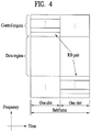
- FIG. 4 illustrates a UL subframe structure.
- a UL subframe may be divided into a control region and a data region in the frequency domain.
- a Physical Uplink Control Channel (PUCCH) carrying Uplink Control Information (UCI) is allocated to the control region and a Physical Uplink Shared Channel (PUSCH) carrying user data is allocated to the data region.
- PUCCH Physical Uplink Control Channel
- PUSCH Physical Uplink Shared Channel
- a UE does not transmit a PUSCH and a PUCCH simultaneously.
- a PUCCH for a UE is allocated to an RB pair in a subframe. The RBs of the RB pair occupy different subcarriers in the two slots of the subframe. Thus it is said that the RB pair allocated to the PUCCH is frequency-hopped over a slot boundary.
- LTE-A (release 10) defines DCI formats 0, 1, 1A, 1B, 1C, 1D, 2, 2A, 2B, 2C, 3, 3A, and 4.
- DCI formats 0, 1A, 3, and 3A have the same message size to reduce the number of blind decodings as described later. According to the usages of control information transmitted in these DCI formats, the DCI formats are classified into i) DCI formats 0 and 4 used for a UL grant, ii) DCI formats 1, A, 1B, 1C, 1D, 2, 2A, 2B, and 2C used for DL scheduling assignments, and iii) DCI formats 3 and 3A used for transmitting TPC commands.
- DCI format 0 used for transmission of a UL grant may include a carrier offset required for later-described Carrier Aggregation (CA) (carrier indicator), an offset that differentiates DCI format 0 from DCI format 1A (flag for format 0/format 1A differentiation), a flag indicating whether frequency hopping applies to PUSCH transmission (frequency hopping flag), information about allocation of RBs to PUSCH transmission of a UE (frequency hopping flag), a Modulation and Coding Scheme (MCS), a new data indicator used to flush a buffer for an initial transmission in relation to an HARQ process, a TPC command for a scheduled PUSCH, cyclic shift information about a Demodulation Reference Signal (DMRS) (cyclic shift for DMRS and Orthogonal Code Cover (OCC) index), a UL index required for a Time Division Duplexing (TDD) operation, Channel Quality Indicator (CQI) request information (CSI request), etc.
- CA Carrier Aggregation
- OCC Orthogonal Code Cover
- DCI format 0 uses synchronous HARQ, DCI format 0 does not include a Redundancy Version (RV), compared to the DCI formats related to DL scheduling assignments. If cross carrier scheduling is not used, the carrier indicator is not included in the DCI format.
- RV Redundancy Version
- DCI format 4 is added to LTE-A release 10, with the aim to support spatial multiplexing for UL transmission. Compared to DCI format 0, DCI format 4 further includes spatial multiplexing information, thus having a relatively large message size. In addition to control information included in DCI format 0, DCI format 4 further includes other control information. Specifically, DCI format 4 further includes an MCS for a second transport block, precoding information for Multiple Input Multiple Output (MIMO) transmission, and a Sounding Reference Signal (SRS) request. Because DCI format 4 is larger than DCI format 0 in size, DCI format 4 does not include a flag for format 0/format 1A differentiation.
- MIMO Multiple Input Multiple Output
- SRS Sounding Reference Signal
- DCI formats 1, 1A, 1B, 1C, 1D, 2, 2A, 2B, and 2C related to DL scheduling assignments DCI formats 1, 1A, 1B, 1C, and 1D do not support spatial multiplexing, whereas DCI formats 2, 2A, 2B, and 2C support spatial multiplexing.
- DCI format 1C supports only contiguous frequency allocation as a compact DL assignment. Compared to other DCI formats, DCI format 1C does not include a carrier indicator and an RV.
- DCI format 1A is used for DL scheduling and a random access procedure.
- DCI format 1A may include a carrier indicator, an indicator indicating whether distributed DL transmission is used, PDSCH resource allocation information, an MCS, an RV, an HARQ process number indicating a processor used for soft combining, a new data indicator used to flush a buffer for an initial transmission in relation to an HARQ process, a TPC command for a PUCCH, a UL index required for a TDD operation, etc.
- Control information of DCI format 1 is mostly similar to control information of DCI format 1A except that DCI format 1 is related to contiguous resource allocation and DCI format 1A supports non-contiguous resource allocation. Accordingly, DCI format 1 further includes a resource allocation header, thereby increasing control signaling overhead as a trade-off of an increase in resource allocation flexibility.
- DCI formats 1B and 1D are common in that they further include precoding information, compared to DCI format 1.
- DCI format 1B carries Precoding Matrix Index (PMI) confirmation and DCI format 1D carries DL power offset information.
- PMI Precoding Matrix Index
- Other control information included in DCI formats 1B and 1D is mostly identical to control information of DCI format 1A.
- DCI formats 2, 2A, 2B, and 2C basically include most of the control information included in DCI format 1A and further include spatial multiplexing information.
- the spatial multiplexing information includes an MCS for a second transport block, a new data indicator, and an RV.
- DCI format 2 supports closed-loop spatial multiplexing and DCI format 2A supports open-loop spatial multiplexing. Both DCI formats 2 and 2A include precoding information.
- DCI format 2B supports dual-layer spatial multiplexing combined with beamforming, further including cyclic shift information for DMRS.
- DCI format 2C is an extension of DCI format 2B, supporting spatial multiplexing of up to 8 layers.
- DCI formats 3 and 3A may be used to support TPC information included in the DCI formats used for transmission of a UL grant and DL scheduling assignments, for semi-persistent scheduling.
- a 1-bit command is used per UE in DCI format 3 and a 2-bit command is used per UE in DCI format 3A.
- One of the above-described DCI formats may be transmitted on one PDCCH and a plurality of PDCCHs may be transmitted in the control region of a subframe.
- a UE may monitor a plurality of PDCCHs.
- DL control channels may be transmitted in the first 3 OFDM symbols of each subframe.
- One to three OFDM symbols may be used according to the overhead of DL control channels.
- a PCFICH may be used to adjust the number of OFDM symbols for DL control channels in each subframe.
- a PHICH may carry an ACK/NACK on a DL in response to a UL transmission.
- a PDCCH may deliver control information required for DL or UL data transmission.
- FIGS. 5 and 6 illustrate allocation of the above-described control channels in units of an REG in the control region of each subframe.
- FIG 5 illustrates a system with a 1 Transmission (1Tx) or 2Tx antenna configuration
- FIG. 6 illustrates a system with a 4Tx antenna configuration.
- a basic resource unit of allocating a control channel, REG includes 4 contiguous REs except for REs carrying RSs in the frequency domain.
- a predetermined number of REGs may be used to transmit a DL control channel according to the overhead of the DL control channel.
- PCFICH Physical Control Format Indicator Channel
- the PDCCH may be transmitted in OFDM symbols ranging from OFDM symbol 0 to OFDM symbol 2 of each subframe to provide resource allocation information about the subframe.
- the PDCCH may be transmitted in OFDM symbol 0, in OFDM symbol 0 and OFDM symbol 1, and in OFDM symbol 0, OFDM symbol 1, and OFDM symbol 2.
- the number of OFDM symbols for a control channel may be changed in each subframe and this information may be provided through the PCFICH. Accordingly, the PCFICH should be transmitted in every subframe.
- the PCFICH may provide three pieces of information. [Table 1] below lists the Control Format Indicator (CFI) values of the PCFICH. If the CFI is 1, this implies that the PDCCH is transmitted in OFDM symbol 0. If the CFI is 2, this implies that the PDCCH is transmitted in OFDM symbol 0 and OFDM symbol 1. If the CFI is 3, this implies that the PDCCH is transmitted in OFDM symbol 0, OFDM symbol 1, and OFDM symbol 2.
- CFI Control Format Indicator
- Information delivered on the PCFICH may be defined differently according to a system bandwidth. For example, if the system bandwidth is narrower than a specific threshold, the CFIs of 1, 2, and 3 may mean that the PDCCH is transmitted in 2, 3, and 4 OFDM symbols, respectively.
- FIG 7 illustrates a PCFICH transmission scheme.
- an REG includes 4 subcarriers which are data subcarriers other than RS REs.
- transmit diversity may apply to the REG
- the REG may be shifted in frequency in each cell (i.e. according to a cell ID) to prevent inter-cell interference.
- the PCFICH is always transmitted in the first OFDM symbol (OFDM symbol 0) of a subframe. Therefore, upon receipt of a subframe, a receiver may determine the number of OFDM symbols occupied by the PDCCH by detecting information from the PCFICH in the subframe, and then may receive control information on the PDCCH.
- PHICH Physical Hybrid-ARQ Indicator Channel
- FIG. 8 illustrates general positions of a PCFICH and PHICHs in a specific bandwidth.
- a PHICH delivers an ACK/NACK for a UL data transmission.
- a plurality of PHICH groups are formed in one subframe and one PHICH group includes a plurality of PHICHs. Accordingly, one PHICH group includes PHICHs for a plurality of UEs.
- a PHICH for each UE in the plurality of PHICH groups is allocated by a lowest Physical RB (PRB) index of a PUSCH resource allocation and a DMRS cyclic shift indicated by a UL grant on a PDCCH.
- a DMRS is a UL reference signal transmitted along with a UL signal, for channel estimation by which to demodulate UL data.
- PHICH resources are indicated by an index pair such as n PHICH group n PHICH seq .
- n PHICH group is a PHICH group number and n PHICH seq is an orthogonal sequence index in a PHICH group with the PHICH group number.
- n PHICH group and n PHICH seq are determined by [Equation 1].
- n DMRS is a cyclic shift value for DMRSs used in a UL transmission associated with the PHICH, mapped to a value of the 'cyclic shift for DMRS' field of the latest UL grant control information (e.g., DCI format 0/4) for a transport block related to a corresponding PUSCH transmission.
- the 'cyclic shift for DMRS' field of the latest DCI format for a UL grant may be 3 bits in size. If this field has value '000', n DMRS may be set to '0'.
- N SF PHICH is a Spreading Factor (SF) size used for PHICH modulation
- I PRB_RA lowest_index is a lowest PRB index of the first slot of the PUSCH transmission.
- N PHICH group is the number of PHICH groups configured by a high layer, calculated by [Equation 2].
- N PHICH group ⁇ ⁇ N g N RB DL / 8 ⁇ for normal cyclic prefix 2 ⁇ ⁇ N g N RB DL / 8 ⁇ for extended cyclic prefix
- N g is information about the amount of PHICH resources, expressed in 2 bits transmitted on a Physical Broadcast Channel (PBCH) ( N g ⁇ 1/6,1/2, 1,2 ⁇ )
- N RB DL is the number of DL RBs.
- [Table 2] illustrates exemplary orthogonal sequences defined in the legacy 3GPP LTE release-8/release-9.
- FIG 9 illustrates the positions of DL REs to which PHICH groups are mapped.
- a PHICH group may be configured in a different time area (i.e. a different OFDM Symbol (OS)) in a subframe according to a PHICH duration, as illustrated in FIG 9 .
- OS OFDM Symbol
- PDCCH-RE mapping is performed in CCEs, which are contiguous logical allocation units.
- One CCE includes a plurality of (e.g. 9) REGs, each REG having four adjacent REs except for RS REs.
- the number of CCEs required for a specific PDCCH depends on DCI payload (i.e. a control information size), a cell bandwidth, a channel coding rate, etc.
- the number of CCEs for a specific PDCCH may be defined according to a PDCCH format, as illustrated in [Table 3].
- one of the above four formats is used for a PDCCH, which is not known to a UE. Therefore, the UE should decode the PDCCH without knowledge of the PDCCH format. This is called blind decoding.
- blind decoding because decoding of all possible DL CCEs for each PDCCH format may impose a great constraint on the UE, a search space is defined in consideration of scheduler restrictions and the number of decoding attempts.
- a search space is a set of candidate PDCCHs formed by CCEs at a given aggregation level, which the UE is supposed to attempt to decode.
- Aggregation levels and the number of PDCCH candidates for each aggregation level may be defined as follows. [Table 4] Search space Number of PDCCH candidates Aggregation level Size (in CCEs) UE-specific 1 6 6 2 12 6 4 8 2 8 16 2 Common 4 16 4 8 16 2
- Search spaces may be classified into a UE-specific Search Space (USS) and a Common Search Space (CSS).
- USS UE-specific Search Space
- SCS Common Search Space
- the USS is configured for specific UEs.
- Each of the UEs may monitor the USS (may attempt to decode a set of PDCCH candidates according to possible DCI formats) and verify an RNTI masked with a PDCCH and a CRC of the PDCCH. If the RNTI and CRC are valid, the UE may acquire control information from the PDCCH.
- the CSS is designed for the case where a plurality of UEs or all UEs need to receive a PDCCH, for example, for dynamic scheduling of system information or a paging message. Nonetheless, the CSS may be used for a specific UE depending on resource management.
- the CSS may overlap with the USS.
- a search space may be determined by [Equation 3].
- L is an aggregation level
- Y k is a variable determined by an RNTI and subframe number k.
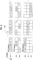
- FIG 10 illustrates a USS (shaded) at each aggregation level, as defined by [Equation 3].
- CA is not adopted and N CCE,k is set to 32, for the convenience of description.
- FIG 10 illustrate USSs at aggregation levels 1, 2, 4, and 8, respectively.
- a number indicates a CCE number.
- the start CCE of a search space at each aggregation level is determined by an RNTI and subframe number k.
- the start CCE of a search space may be different in the same subframe according to an aggregation level due to a modulo function and L.
- the start CCE of a search space is always a multiple of an aggregation level due to L .
- Y k is CCE 18.
- the UE attempts to decode in units of CCEs determined by an aggregation level, starting from the start CCE. For example, the UE attempts to decode in units of two CCEs according to an aggregation level, starting from CCE 4 in (b) of FIG. 10 .
- the UE attempts to decode a search space.
- the number of decodings is determined by a DCI format and a transmission mode indicated by Radio Resource Control (RRC) signaling.
- RRC Radio Resource Control
- the UE needs to attempt 12 decodings at maximum in a CSS, in consideration of two DCI sizes (DCI format 0/1A/3/3A and DCI format 1C) for each of six PDCCH candidates.
- the maximum number of decodings is increased because as many decodings as the number of DL resources (DL Component Carriers (CCs)) are added for a USS and DCI format 4).
- DL Component Carriers CCs
- a UE receives DCI on a PDCCH transmitted in resources indicated by a PCFICH.
- allocation of a new PDCCH having a new structure and transmitted in a new transmission mode to a PDSCH region is under discussion in a system conforming to LTE release-11 and beyond, in consideration of various cell deployment scenarios such as Remote Radio Heads (RRHs) and MIMO such as closed-loop beamforming based on a UE's feedback.
- RRHs Remote Radio Heads
- MIMO such as closed-loop beamforming based on a UE's feedback.
- the newly defined PDCCH will be referred to as an Enhanced PDCCH (E-PDCCH) and an existing PDCCH will be referred to as a legacy PDCCH or a PDCCH.
- E-PDCCH Enhanced PDCCH
- legacy PDCCH or a PDCCH.
- the legacy PDCCH is transmitted in the first to fourth OFDM symbols of a DL subframe, OFDM symbol 0 to OFDM symbol 3, and if the DL bandwidth N RB DL > 10 , the legacy PDCCH is transmitted in the first to third OFDM symbols of the DL subframe, OFDM symbol 0 to OFDM symbol 2.
- the legacy PDCCH may be configured to span various ranges according to the type of a DL subframe (e.g. normal subframe, Multicast Broadcast Single Frequency Network (MBSFN) subframe, special subframe, etc.) and a PHICH duration as well as a system bandwidth.
- MBSFN Multicast Broadcast Single Frequency Network
- a CFI indicating the range of the legacy PDCCH is signaled to a UE by a PCFICH in each DL subframe.
- the range of a PDCCH indicated by a CFI transmitted on a PCFICH is determined as illustrated in [Table 5].
- a PHICH duration indicated by a PBCH determines a lower limit of the PDCCH range. Accordingly, if N RB DL > 10 and an extended PHICH duration is configured, the UE operates on the assumption that the CFI is identical to the extended PHICH duration.
- the PDCCH starts from the first OFDM symbol (OFDM symbol 0) of a subframe and the range/size of the PDCCH is determined according to the type of the subframe and a PHICH duration in the legacy LTE/LTE-A system.
- the index of the start symbol of a resource region carrying the E-PDCCH may vary according to a carrier type, legacy control channels, or transmission or non-transmission of new control channels (e.g. Enhanced PHICH (E-PHICH), Enhanced PCFICH (E-PCFICH), etc.) related to the E-PDCCH.
- E-PHICH Enhanced PHICH
- E-PCFICH Enhanced PCFICH
- the start OFDM symbol of an E-PDCCH may be determined by a function of a higher-layer parameter transmitted by UE-specific or cell-specific higher-layer signaling and the type of a DL subframe carrying the E-PDCCH.
- the RRC parameter transmitted by UE-specific or cell-specific RRC signaling may be 'startOFDMsymbol' (the name of the parameter is exemplary). i) If N RB DL ⁇ 10 , 'startOFDMsymbol' may be one of OFDM symbol index 0, 2, 3, or 4 and ii) if N RB DL > 10 , 'startOFDMsymbol' may be one of OFDM symbol index 0, 1, 2, or 3. Specifically, 'startOFDMsymbol' may be configured as listed in [Table 7]. [Table 7] Configuration startOFDMsymbol, when N RB DL > 10 startOFDMsymbol, when N RB DL ⁇ 10 0 1 2 1 2 3 2 3 4 3 0 0 0
- 'startOFDMsymbol' may be 0 irrespective of the DL bandwidth is larger than 10 RBs or equal to or smaller than 10 RBs.
- this case may apply to a new carrier type that may be defined after LTE release-11.
- the actual start OFDM symbol of the E-PDCCH may be determined based on 'startOFDMsymbol' configured in the above manner, a system bandwidth, and a subframe type, as illustrated in [Table 8].
- Subframe 1 and 6 for frame structure type 2 # min(2, startOFDMsymbol ) #2 MBSFN subframes on a carrier supporting PDSCH, configured with 1 or 2 cell-specific antenna ports # min(2, startOFDMsymbol ) #2 MBSFN subframes on a carrier supporting PDSCH, configured with 4 cell-specific antenna ports #2 #2 Subframes on a carrier not supporting PDSCH N/A N/A Non-MBSFN subframes (except subframe 6 for frame structure type 2) configured with positioning reference signals # startOFDMsymbol # min(3, startOFDMsymbol ) All
- the start OFDM symbol index of the E-PDCCH may be set to 'startOFDMsymbol' indicated by higher-layer signaling. If a special subframe or an MBSFN subframe carries the E-PDCCH and the DL bandwidth is larger than 10 RBs, the start OFDM symbol index of the E-PDCCH may be set to the smaller value between 2 and 'startOFDMsymbol'. If a special subframe or an MBSFN subframe carries the E-PDCCH and the DL bandwidth is equal to or smaller than 10 RBs, the start OFDM symbol index of the E-PDCCH may be set to 2.
- a parameter that configures the start OFDM symbol of the E-PDCCH may be transmitted for each subframe type.
- the start OFDM symbol configuration parameter ('startOFDMsymbol') may be configured separately into a start OFDM symbol configuration parameter ('startOFDMsymbolnonMBSFN') for a non-MBSFN subframe and a start OFDM symbol configuration parameter ('startOFDMsymbolMBSFN') for an MBSFN subframe.
- start OFDM symbol index of an E-PDCCH in a non-MBSFN subframe may be determined by 'startOFDMsymbolnonMBSFN'
- the start OFDM symbol index of an E-PDCCH in an MBSFN subframe may be determined by 'startOFDMsymbolMBSFN'.
- start OFDM symbol configuration parameters may be configured respectively for three types of subframes, non-MBSFN subframe, normal subframe, and special subframe. That is, the start OFDM symbol index of an E-PDCCH in an MBSFN subframe may be determined by 'startOFDMsymbolMBSFN'. In the case of a non-MBSFN subframe, the start OFDM symbol index of an E-PDCCH in a normal subframe may be determined by 'startOFDMsymbolnormal' and the start OFDM symbol index of an E-PDCCH in a special subframe may be determined by 'startOFDMsymbolspecial'.
- a single RRC parameter ('startOFDMsymbol') is configured to indicate the start OFDM symbol of an E-PDCCH in [Table 8]
- two RRC parameters 'startOFDMsymbol1' and 'startOFDMsymbol2' may be configured and a value between the two parameters may be selected for each subframe, referring to a mapping table such as [Table 9] below.
- Subframe 1 and 6 for frame structure type 2 # startOFDMsymbol1 #2 MBSFN subframes on a carrier supporting PDSCH, configured with 1 or 2 cell-specific antenna ports # startOFDMsymbol1 #2 MBSFN subframes on a carrier supporting PDSCH, configured with 4 cell-specific antenna ports #2 #2
- a PHICH duration configured by higher-layer signaling may impose a lower limit on the start OFDM symbol index of the E-PDCCH. That is, in the case of a normal PHICH duration, the E-PDCCH may start from OFDM symbol 1. In the case of an extended PHICH duration, the E-PDCCH may start from OFDM symbol 2 or OFDM symbol 3 according to a subframe type, as illustrated in [Table 2].
- the start OFDM symbol of the E-PDCCH may not be affected by a PHICH duration. Rather, the start OFDM symbol of the E-PDCCH may be determined based on the higher-layer configuration parameter 'startOFDMsymbol' and a subframe type, referring to only [Table 8] or [Table 9].
- the start OFDM symbol of an E-PDCCH is fixed to a predetermined position.
- the start OFDM symbol position of the E-PDCCH may be determined separately for a backward compatible carrier carrying a legacy PDCCH and a new carrier without a legacy PDCCH, which may be defined after LTE release-11.
- the start OFDM symbol of an E-PDCCH may be determined to be the first OFDM symbol of a subframe in the new carrier, irrespective of a DL bandwidth on the assumption that the new carrier does not carry a legacy control channel. Or if N RB DL > 10 by UE-specific or cell-specific higher-layer signaling, the start OFDM symbol of an E-PDCCH may be determined to be one of OFDM symbol #0, #1, #2, or #3 and if N RB DL ⁇ 10 by UE-specific or cell-specific higher-layer signaling, the start OFDM symbol of an E-PDCCH may be determined to be one of OFDM symbol #0, #2, #3, or #4.
- start OFDM symbol indexes for an E-PDCCH may be configured as illustrated in [Table 10] in consideration of a maximum size of a legacy PDCCH determined based on a system bandwidth and a subframe type.
- the start OFDM symbol of an E-PDCCH may be determined based on the size of a legacy PDCCH, whereas in the case of a new carrier type, the start OFDM symbol of an E-PDCCH may be fixed to OFDM symbol 0 or determined by a higher-layer configuration.
- the start OFDM symbol of an E-PDCCH is determined in consideration of the actual size of a legacy PDCCH in the case of a backward compatible carrier.
- the UE may set the start OFDM symbol of an E-PDCCH to the OFDM symbol next to an ending OFDM symbol of the legacy PDCCH.
- a new CFI (hereinafter, referred to as an Enhanced CFI (E-CFI) distinguishably from a CFI for a legacy PDCCH) is defined to configure the start OFDM symbol of an E-PDCCH and transmitted on a new DL channel, E-PCFICH.
- E-CFI Enhanced CFI
- the E-PCFICH may be transmitted at a fixed position of a legacy PDCCH (specific CCEs, for example, 8 CCEs ranging from CCE 0 to CCE 8 or the last 8 CCEs of the legacy PDCCH).
- an E-PCFICH RNTI is newly defined and DCI with a CRC scrambled with the E-PCFICH RNTI is transmitted in a CSS of the legacy PDCCH, so that a UE may receive the E-PCFICH by blind decoding.
- the E-PCFICH may be transmitted in a specific RB of a PDSCH region.
- the E-PCFICH may be transmitted in two PRBs at both edges of a total DL bandwidth.
- an eNB may transmit RB allocation information about a CSS for an E-PDCCH or RB allocation information about a distributed E-PDCCH, on the E-PCFICH.
- the eNB may configure the start OFDM symbol ('startOFDMsymbol') of an E-PDCCH through the E-PCFICH as illustrated in [Table 7].
- the start OFDM symbol of the E-PDCCH CSS may be preferably fixed to avoid ambiguity involved in a higher-layer configuration. Therefore, the present invention proposes that the start OFDM symbols of an E-PDCCH CSS and an E-PDCCH USS are defined individually/separately in order to configure the start OFDM symbol of an E-PDCCH. In other words, the start OFDM symbol of one or more RB pairs (PRB pairs and/or VRB pairs) in the CSS and the start OFDM symbol of one or more RB pairs in the USS are configured separately.
- the start OFDM symbol of one or more RB pairs in the CSS may be fixed, especially in consideration of variable OFDM symbols occupied by a legacy control channel on a backward compatible carrier.
- the start OFDM symbol may be set to a 4 th OFDM symbol, or may be fixed according to a subframe type as illustrated in [Table 10] in Embodiment 2.
- the start OFDM symbol of one or more RB pairs in the USS may be determined according to any of Embodiment 1 to Embodiment 3.
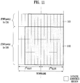
- Embodiment 5 An example of Embodiment 5 will be described with reference to FIG 11 .
- one of four (P)RB pairs is used for a CSS and the other three (P)RB pairs are used for a USS.
- An E-PDCCH resource region 1101 including the CSS starts from a fourth OFDM symbol and an E-PDCCH resource region 1103 including the USS starts from a third OFDM symbol.
- the start OFDM symbol of the E-PDCCH resource region 1103 including the USS is configured according to [Table 8] in Embodiment 1. While the resource regions including the CSS and the USS start from different OFDM symbols in FIG 11 , the resource regions may start from the same OFDM symbol by implementing any of the foregoing embodiments.
- FIG 12 is a block diagram of an eNB and a UE according to an embodiment of the present invention.
- an eNB 1210 may include a Reception (Rx) module 1211, a Tx module 1212, a processor 1213, a memory 1214, and a plurality of antennas 1215.
- the plurality of antennas 1215 are used to support MIMO transmission and reception.
- the Rx module 1211 may receive UL signals, data and information from a UE.
- the Tx module 1212 may transmit DL signals, data and information to a UE.
- the processor 1213 may provide overall control to the operations of the eNB 1210 and operate to implement the foregoing embodiments of the present invention.
- the processor 1213 may process information received by the eNB 1210 and information to be transmitted from the eNB 1210.
- the memory 1214 may store the processed information for a predetermined time and may be replaced with a component such as a buffer (not shown).
- a UE 1220 may include an Rx module 1221, a Tx module 1222, a processor 1223, a memory 1224, and a plurality of antennas 1225.
- the plurality of antennas 1225 are used to support MIMO transmission and reception.
- the Rx module 1221 may receive DL signals, data, and information from an eNB.
- the Tx module 1222 may transmit UL signals, data, and information to an eNB.
- the processor 1223 may provide overall control to the operations of the UE 1220 and may implement the afore-described embodiments of the present invention.
- the processor 1223 may process information received by the UE 1220 and information to be transmitted from the UE 1220.
- the memory 1224 may store the processed information for a predetermined time and may be replaced with a component such as a buffer (not shown).
- One or more of the above-described embodiments of the present invention may apply to the configurations of the eNB and the UE, independently or in combination. Redundant descriptions are avoided for clarity.
- the description of the eNB 1210 may apply to a relay as a DL transmission entity or a UL reception entity, and the description of the UE 1220 may apply to the relay as a DL reception entity or a UL transmission entity in FIG 12 .
- an embodiment of the present invention may be achieved by various means, for example, hardware, firmware, software, or a combination thereof.
- an embodiment of the present invention may be achieved by one or more ASICs (application specific integrated circuits), DSPs (digital signal processors), DSDPs (digital signal processing devices), PLDs (programmable logic devices), FPGAs (field programmable gate arrays), processors, controllers, microcontrollers, microprocessors, etc.
- ASICs application specific integrated circuits
- DSPs digital signal processors
- DSDPs digital signal processing devices
- PLDs programmable logic devices
- FPGAs field programmable gate arrays
- processors controllers, microcontrollers, microprocessors, etc.
- an embodiment of the present invention may be implemented in the form of a module, a procedure, a function, etc.
- Software code may be stored in a memory unit and executed by a processor.
- the memory unit is located at the interior or exterior of the processor and may transmit and receive data to and from the processor via various known means.
Landscapes
- Engineering & Computer Science (AREA)
- Signal Processing (AREA)
- Computer Networks & Wireless Communication (AREA)
- Quality & Reliability (AREA)
- Databases & Information Systems (AREA)
- Mobile Radio Communication Systems (AREA)
Description
- The present invention relates to a method and apparatus for transmitting/obtaining control information in a wireless communication system.
- Wireless communication systems have been widely deployed in order to provide various types of communication services including voice or data. In general, a wireless communication system is a multiple access system that can support communication with multiple users by sharing available system resources (a bandwidth, transmission power, etc.). Examples of multiple access systems include Code Division Multiple Access (CDMA), Frequency Division Multiple Access (FDMA), Time Division Multiple Access (TDMA), Orthogonal Frequency Division Multiple Access (OFDMA), Single Carrier Frequency Division Multiple Access (SC-FDMA), Multi Carrier Frequency Division Multiple Access (MC-FDMA), etc.
- The document "Design of E-PDCCH search space (R1-113743) ", 3GPP DRAFT, vol. RAN WG1, no. #67, 9 November 2011 (2011-11-09), XP050562240, 3RD GENERATION PARTNERSHIP PROJECT (3GPP), MOBILE COMPETENCE CENTRE; 650, ROUTE DES LUCIOLES; F-06921 SOPHIA-ANTIPOLIS CEDEX; FRANCE, by CATT as retrieved on 2011-11-09, discloses a method for a acquiring control information via an enhanced physical downlink control channel, EPCCH at a user equipment in a wireless communication system, comprising the determination of an index of a start orthogonal frequency division multiplexing (OFDM) symbol of an ePDCCH in a subframe, and attempting to perform decoding on a UE-specific search space of the ePDCCH, wherein the index of the start OFDM symbol of the ePDCCH is determined based on at least one of a higher layer parameter or a control format indicator (FCI) value. Late-published
document EP 2 775 768 A1 discloses a sending method and apparatus for enhanced physical downlink control channel, the method comprising a start position of the ePDCCH in a subframe being determined according to a high level signaling and/or preset rule, and a pilot signal for ePDCCH and data carried on the ePDCCH being sent. The interference between the ePDCCH and the downlink control channel is reduced, and the efficiency of the downlink transmission is improved. - The present invention relates to a method and apparatus for transmitting/receiving control infonnation. More particularly, the present invention relates to, if control information is transmitted on an Enhanced Physical Downlink Control Channel (E-PDCCH), determination of a starting Orthogonal Frequency Division Multiplexing (OFDM) symbol of a resource region in which the E-PDCCH is transmitted.
- In an aspect of the present invention, a method for acquiring control information on an Enhanced Physical Downlink Control Channel (E-PDCCH) at a User Equipment (UE) in a wireless communication system includes performing blind decoding on a common search space in a set of first Resource Blocks (RBs) of a subframe, and performing blind decoding on a UE-specific search space in a set of second RBs of the subframe. A first start OFDM symbol of an E-PDCCH resource region including the common search space in the set of first RBs and a second start OFDM symbol of an E-PDCCH resource region including the UE-specific search space in the set of second RBs are determined separately.
- In another aspect of the present invention, a method for transmitting control information on an E-PDCCH at a BS in a wireless communication system includes allocating a common search space in a set of first RBs of a subframe, and allocating a UE-specific search space in a set of second RBs of the subframe. A first start OFDM symbol of an E-PDCCH resource region including the common search space in the set of first RBs and a second start OFDM symbol of an E-PDCCH resource region including the UE-specific search space in the set of second RBs are determined separately.
- In another aspect of the present invention, a UE for acquiring control information on an E-PDCCH in a wireless communication system includes a reception module, and a processor. The processor performs blind decoding on a common search space in a set of first RBs of a subframe and performs blind decoding on a UE-specific search space in a set of second RBs of the subframe. A first start OFDM symbol of an E-PDCCH resource region including the common search space in the set of first RBs and a second start OFDM symbol of an E-PDCCH resource region including the UE-specific search space in the set of second RBs are determined separately.
- In a further aspect of the present invention, a BS for transmitting control information on an E-PDCCH in a wireless communication system includes a transmission module, and a processor. The processor allocates a common search space in a set of first RBs of a subframe and allocates a UE-specific search space in a set of second RBs of the subframe. A first start OFDM symbol of an E-PDCCH resource region including the common search space in the set of first RBs and a second start OFDM symbol of an E-PDCCH resource region including the UE-specific search space in the set of second RBs are determined separately.
- The first and second aspects of the present invention may include all or a part of the followings.
- The index of the first start OFDM symbol may be fixed to 4.
- The index of the second start OFDM symbol may be determined based on at least one of a type of the subframe or a higher-layer signaled value. If the subframe is a normal subframe, the index of the second start OFDM symbol may be the higher-layer signaled value. If the subframe is one of a special subframe or a Multicast-Broadcast Single Frequency Network (MBSFN) subframe and includes more than 10 RBs, the index of the second start OFDM symbol may be a smaller value between 2 and the higher-layer signaled value. If the subframe is one of a special subframe or an MBSFN subframe and includes 10 or fewer RBs, the index of the second start OFDM symbol may be 2.
- According to the present invention, when control information is transmitted on an Enhanced Physical Downlink Control Channel (E-PDCCH), a start OFDM symbol of a resource region carrying the E-PDCCH is defined. Therefore, a User Equipment (UE) can perform blind decoding without ambiguity.
- It will be appreciated by persons skilled in the art that the effects that can be achieved with the present invention are not limited to what has been particularly described hereinabove and other advantages of the present invention will be more clearly understood from the following detailed description taken in conjunction with the accompanying drawings.
-
-
FIG. 1 illustrates a structure of a downlink radio frame; -
FIG. 2 illustrates an exemplary resource grid for the duration of one downlink slot; -
FIG. 3 illustrates a structure of a downlink subframe; -
FIG. 4 illustrates a structure of an uplink subframe; -
FIGS. 5 and 6 are views referred to for describing a downlink control channel allocation unit, Resource Element Group (REG); -
FIG. 7 illustrates a Physical Control Format Indicator Channel (PCFICH) transmission scheme; -
FIG. 8 illustrates the positions of a PCFICH and Physical HARQ Indicator Channels (PHICHs); -
FIG. 9 illustrates the positions of downlink Resource Elements (REs) to which PHICH groups are mapped; -
FIG. 10 illustrates a search space for each aggregation level; -
FIG. 11 illustrates determination of a starting Orthogonal Frequency Division Multiplexing (OFDM) symbol according to an embodiment of the present invention; and -
FIG. 12 is a block diagram of an evolved Node B (eNB) and a User Equipment (UE) according to the present invention. - The following description illustrates both the embodiments of the invention that comprise the features of the independent claims and other embodiments of related inventions that do not comprise all the features of the independent claims but are useful for better understanding the claimed invention. In the embodiments of the present invention, a description is made, centering on a data transmission and reception relationship between a Base Station (BS) and a User Equipment (UE). The BS is a terminal node of a network, which communicates directly with a UE. In some cases, a specific operation described as performed by the BS may be performed by an upper node of the BS.
- Namely, it is apparent that, in a network comprised of a plurality of network nodes including a BS, various operations performed for communication with a UE may be performed by the BS or network nodes other than the BS. The term 'BS' may be replaced with the term 'fixed station', 'Node B', 'evolved Node B (eNode B or eNB)', 'Access Point (AP)', etc. The term 'relay' may be replaced with the term 'Relay Node (RN)' or 'Relay Station (RS)'. The term 'terminal' may be replaced with the term 'UE', 'Mobile Station (MS)', 'Mobile Subscriber Station (MSS)', 'Subscriber Station (SS)', etc.
- Specific terms used for the embodiments of the present invention are provided to help the understanding of the present invention. In some instances, to prevent the concept of the present invention from being ambiguous, structures and apparatuses of the known art will be omitted, or will be shown in the form of block diagram based on main functions of each structure and apparatus. Also, wherever possible, like reference numerals denote the same parts throughout the drawings and the specification.
- The embodiments of the present invention can be supported by standard documents disclosed for at least one of wireless access systems, Institute of Electrical and Electronics Engineers (IEEE) 802, 3<rd>Generation Partnership Project (3GPP), 3GPP Long Term Evolution (3GPP LTE), LTE-Advanced (LTE-A), and 3GPP2. Steps or parts that are not described to clarify the technical features of the present invention can be supported by those specifications. Further, all terms as set forth herein can be explained by the standard specifications.
- Techniques described herein can be used in various wireless access systems such as Code Division Multiple Access (CDMA), Frequency Division Multiple Access (FDMA), Time Division Multiple Access (TDMA), Orthogonal Frequency Division Multiple Access (OFDMA), Single Carrier Frequency Division Multiple Access (SC-FDMA), etc. CDMA may be implemented as a radio technology such as Universal Terrestrial Radio Access (UTRA) or CDMA2000. TDMA may be implemented as a radio technology such as Global System for Mobile communications (GSM)/General Packet Radio Service (GPRS)/Enhanced Data Rates for GSM Evolution (EDGE). OFDMA may be implemented as a radio technology such as IEEE 802.11 (Wi-Fi), IEEE 802.16 (WiMAX), IEEE 802.20, Evolved-UTRA (E-UTRA) etc. UTRA is a part of Universal Mobile Telecommunications System (UMTS). 3GPP LTE is a part of Evolved UMTS (E-UMTS) using E-UTRA. 3GPP LTE employs OFDMA for Downlink (DL) and SC-FDMA for Uplink (UL). LTE-A is an evolution of 3GPP LTE. WiMAX can be described by the IEEE 802.16e standard (Wireless Metropolitan Area Network (WirelessMAN)-OFDMA Reference System) and the IEEE 802.16m standard (WirelessMAN-OFDMA Advanced System). For clarity, the present disclosure focuses on the 3GPP LTE and LTE-A systems. However, the technical features of the present invention are not limited thereto.
-
FIG 1 illustrates a radio frame structure in a 3GPP LTE system. Referring toFIG 1(a) , a radio frame is divided into 10 subframes. Each subframe is further divided into two slots in the time domain. A unit time during which one subframe is transmitted is defined as a Transmission Time Interval (TTI). For example, one subframe may be 1ms in duration and one slot may be 0.5ms in duration. A slot may include a plurality of Orthogonal Frequency Division Multiplexing (OFDM) symbols in the time domain. Because the 3GPP LTE system adopts OFDMA for DL, an OFDM symbol represents one symbol period. An OFDM symbol may be referred to as an SC-FDMA symbol or symbol period on UL. A Resource Block (RB) is a resource allocation unit including a plurality of contiguous subcarriers in a slot. This radio frame structure is purely exemplary. Therefore, the number of subframes in a radio frame, the number of slots in a subframe, or the number of OFDM symbols in a slot may vary. -
FIG 1(b) illustrates a type-2 radio frame structure. A type-2 radio frame includes two half frames, each having 5 subframes, a Downlink Pilot Time Slot (DwPTS), a Guard Period (GP), and an Uplink Pilot Time Slot (UpPTS). Each subframe is divided into two slots. The DwPTS is used for initial cell search, synchronization, or channel estimation at a UE. The UpPTS is used for channel estimation and acquisition of UL transmission synchronization to a UE at an eNB. The GP is a period between a UL and a DL, which eliminates UL interference caused by multipath delay of a DL signal. - The above-described radio frame structure is purely exemplary and thus it is to be noted that the number of sub frames in a radio frame, the number of slots in a subframe, or the number of symbols in a slot may vary.
-
FIG. 2 illustrates a resource grid for the duration of one DL slot. A DL slot includes 7 OFDM symbols in the time domain and an RB includes 12 subcarriers in the frequency domain. For example, a DL slot may include 7 OFDM symbols in the case of a normal Cyclic Prefix (CP), whereas a DL slot may include 6 OFDM symbols in the case of an extended CP. Each element of the resource grid is referred to as a Resource Element (RE). An RB includes 12x7 REs. The number of RBs in a DL slot, N<DL>depends on a DL transmission bandwidth. A UL slot may have the same structure as a DL slot. -
FIG. 3 illustrates a DL subframe structure. Up to 3 OFDM symbols at the start of the first slot of a DL subframe are used for a control region to which control channels are allocated and the other OFDM symbols of the DL subframe are used for a data region to which a Physical Downlink Shared Channel (PDSCH) is allocated. DL control channels used in the 3GPP LTE system include Physical Control Format Indicator Channel (PCFICH), Physical Downlink Control Channel (PDCCH), and Physical Hybrid automatic repeat request (HARQ) Indicator Channel (PHICH). - The PCFICH is transmitted in the first OFDM symbol of a subframe, carrying information about the number of OFDM symbols used for transmission of control channels in the subframe.
- The PHICH delivers an HARQ ACKnowledgment/Negative ACKnowledgment (ACK/NACK) signal in response to a UL transmission.
- Control information transmitted on the PDCCH is called Downlink Control Information (DCI). The DCI transports UL or DL scheduling information, or UL Transmit Power Control (TPC) commands for UE groups. The PDCCH delivers information about resource allocation and a transport format for a Downlink Shared
Channel (DL-SCH), information about resource allocation for an Uplink Shared Channel (UL-SCH), paging information of a Paging Channel (PCH), system information on the DL-SCH, information about resource allocation for a higher-layer control message such as a Random Access Response transmitted on the PDSCH, a set of TPC commands for individual UEs of a UE group, transmission power control information, Voice Over Internet Protocol (VoIP) activation information, etc. A plurality of PDCCHs may be transmitted in the control region. A UE may monitor a plurality of PDCCHs. A PDCCH is transmitted in an aggregate of one or more contiguous Control Channel Elements (CCEs). A CCE is a logical allocation unit used to provide a PDCCH at a coding rate based on the state of a radio channel. A CCE includes a plurality of RE Groups (REGs). The format of a PDCCH and the number of available bits for the PDCCH are determined according to the correlation between the number of CCEs and a coding rate provided by the CCEs. An eNB determines a PDCCH format according to DCI transmitted to a UE and adds a Cyclic Redundancy Check (CRC) to control information. The CRC is masked by an Identifier (ID) known as Radio Network Temporary Identifier (RNTI) according to the owner or usage of the PDCCH. If the PDCCH is directed to a specific UE, its CRC may be masked by a Cell-RNTI (C-RNTI) of the UE. If the PDCCH is used for a paging message, the CRC of the PDCCH may be masked by a Paging Indicator Identifier (P-RNTI). If the PDCCH carries system information, particularly, a System Information Block (SIB), its CRC may be masked by a system information ID and a System Information RNTI (SI-RNTI). To indicate that the PDCCH carries a Random Access Response in response to a Random Access Preamble transmitted by a UE, its CRC may be masked by a Random Access-RNTI (RA-RNTI). -
FIG. 4 illustrates a UL subframe structure. A UL subframe may be divided into a control region and a data region in the frequency domain. A Physical Uplink Control Channel (PUCCH) carrying Uplink Control Information (UCI) is allocated to the control region and a Physical Uplink Shared Channel (PUSCH) carrying user data is allocated to the data region. To maintain a single carrier property, a UE does not transmit a PUSCH and a PUCCH simultaneously. A PUCCH for a UE is allocated to an RB pair in a subframe. The RBs of the RB pair occupy different subcarriers in the two slots of the subframe. Thus it is said that the RB pair allocated to the PUCCH is frequency-hopped over a slot boundary. - LTE-A (release 10) defines DCI formats 0, 1, 1A, 1B, 1C, 1D, 2, 2A, 2B, 2C, 3, 3A, and 4. DCI formats 0, 1A, 3, and 3A have the same message size to reduce the number of blind decodings as described later. According to the usages of control information transmitted in these DCI formats, the DCI formats are classified into i) DCI formats 0 and 4 used for a UL grant, ii) DCI formats 1, A, 1B, 1C, 1D, 2, 2A, 2B, and 2C used for DL scheduling assignments, and iii) DCI formats 3 and 3A used for transmitting TPC commands.
-
DCI format 0 used for transmission of a UL grant may include a carrier offset required for later-described Carrier Aggregation (CA) (carrier indicator), an offset that differentiatesDCI format 0 from DCI format 1A (flag forformat 0/format 1A differentiation), a flag indicating whether frequency hopping applies to PUSCH transmission (frequency hopping flag), information about allocation of RBs to PUSCH transmission of a UE (frequency hopping flag), a Modulation and Coding Scheme (MCS), a new data indicator used to flush a buffer for an initial transmission in relation to an HARQ process, a TPC command for a scheduled PUSCH, cyclic shift information about a Demodulation Reference Signal (DMRS) (cyclic shift for DMRS and Orthogonal Code Cover (OCC) index), a UL index required for a Time Division Duplexing (TDD) operation, Channel Quality Indicator (CQI) request information (CSI request), etc. BecauseDCI format 0 uses synchronous HARQ,DCI format 0 does not include a Redundancy Version (RV), compared to the DCI formats related to DL scheduling assignments. If cross carrier scheduling is not used, the carrier indicator is not included in the DCI format. -
DCI format 4 is added to LTE-A release 10, with the aim to support spatial multiplexing for UL transmission. Compared toDCI format 0,DCI format 4 further includes spatial multiplexing information, thus having a relatively large message size. In addition to control information included inDCI format 0,DCI format 4 further includes other control information. Specifically,DCI format 4 further includes an MCS for a second transport block, precoding information for Multiple Input Multiple Output (MIMO) transmission, and a Sounding Reference Signal (SRS) request. BecauseDCI format 4 is larger thanDCI format 0 in size,DCI format 4 does not include a flag forformat 0/format 1A differentiation. - Among DCI formats 1, 1A, 1B, 1C, 1D, 2, 2A, 2B, and 2C related to DL scheduling assignments, DCI formats 1, 1A, 1B, 1C, and 1D do not support spatial multiplexing, whereas DCI formats 2, 2A, 2B, and 2C support spatial multiplexing.
- DCI format 1C supports only contiguous frequency allocation as a compact DL assignment. Compared to other DCI formats, DCI format 1C does not include a carrier indicator and an RV.
- DCI format 1A is used for DL scheduling and a random access procedure. DCI format 1A may include a carrier indicator, an indicator indicating whether distributed DL transmission is used, PDSCH resource allocation information, an MCS, an RV, an HARQ process number indicating a processor used for soft combining, a new data indicator used to flush a buffer for an initial transmission in relation to an HARQ process, a TPC command for a PUCCH, a UL index required for a TDD operation, etc.
- Control information of
DCI format 1 is mostly similar to control information of DCI format 1A except thatDCI format 1 is related to contiguous resource allocation and DCI format 1A supports non-contiguous resource allocation. Accordingly,DCI format 1 further includes a resource allocation header, thereby increasing control signaling overhead as a trade-off of an increase in resource allocation flexibility. - DCI formats 1B and 1D are common in that they further include precoding information, compared to
DCI format 1. DCI format 1B carries Precoding Matrix Index (PMI) confirmation and DCI format 1D carries DL power offset information. Other control information included in DCI formats 1B and 1D is mostly identical to control information of DCI format 1A. - DCI formats 2, 2A, 2B, and 2C basically include most of the control information included in DCI format 1A and further include spatial multiplexing information. The spatial multiplexing information includes an MCS for a second transport block, a new data indicator, and an RV.
-
DCI format 2 supports closed-loop spatial multiplexing and DCI format 2A supports open-loop spatial multiplexing. Both DCI formats 2 and 2A include precoding information. DCI format 2B supports dual-layer spatial multiplexing combined with beamforming, further including cyclic shift information for DMRS. DCI format 2C is an extension of DCI format 2B, supporting spatial multiplexing of up to 8 layers. - DCI formats 3 and 3A may be used to support TPC information included in the DCI formats used for transmission of a UL grant and DL scheduling assignments, for semi-persistent scheduling. A 1-bit command is used per UE in
DCI format 3 and a 2-bit command is used per UE in DCI format 3A. - One of the above-described DCI formats may be transmitted on one PDCCH and a plurality of PDCCHs may be transmitted in the control region of a subframe. A UE may monitor a plurality of PDCCHs.
- Basically, DL control channels may be transmitted in the first 3 OFDM symbols of each subframe. One to three OFDM symbols may be used according to the overhead of DL control channels. To adjust the number of OFDM symbols for DL control channels in each subframe, a PCFICH may be used. A PHICH may carry an ACK/NACK on a DL in response to a UL transmission. A PDCCH may deliver control information required for DL or UL data transmission.
-
FIGS. 5 and 6 illustrate allocation of the above-described control channels in units of an REG in the control region of each subframe.FIG 5 illustrates a system with a 1 Transmission (1Tx) or 2Tx antenna configuration andFIG. 6 illustrates a system with a 4Tx antenna configuration. As illustrated inFIGS. 5 and 6 , a basic resource unit of allocating a control channel, REG includes 4 contiguous REs except for REs carrying RSs in the frequency domain. A predetermined number of REGs may be used to transmit a DL control channel according to the overhead of the DL control channel. - The PDCCH may be transmitted in OFDM symbols ranging from
OFDM symbol 0 toOFDM symbol 2 of each subframe to provide resource allocation information about the subframe. Depending on the overhead of the PDCCH, the PDCCH may be transmitted inOFDM symbol 0, inOFDM symbol 0 andOFDM symbol 1, and inOFDM symbol 0,OFDM symbol 1, andOFDM symbol 2. The number of OFDM symbols for a control channel may be changed in each subframe and this information may be provided through the PCFICH. Accordingly, the PCFICH should be transmitted in every subframe. - The PCFICH may provide three pieces of information. [Table 1] below lists the Control Format Indicator (CFI) values of the PCFICH. If the CFI is 1, this implies that the PDCCH is transmitted in
OFDM symbol 0. If the CFI is 2, this implies that the PDCCH is transmitted inOFDM symbol 0 andOFDM symbol 1. If the CFI is 3, this implies that the PDCCH is transmitted inOFDM symbol 0,OFDM symbol 1, andOFDM symbol 2.[Table 1] CFI CFI codeword < b0, b1,...,b31 > 1 <0,1,1,0,1,1,0,1,1,0,1,1,0,1,1,0,1,1,0,1,1,0,1,1,0,1,1,0,1,1,0,1> 2 <1,0,1,1,0,1,1,0,1,1,0,1,1,0,1,1,0,1,1,0,1,1,0,1,1,0,1,1,0,1,1,0> 3 <1,1,0,1,1,0,1,1,0,1,1,0,1,1,0,1,1,0,1,1,0,1,1,0,1,1,0,1,1,0,1,1> 4 (Reserved) <0,0,0,0,0,0,0,0,0,0,0,0,0,0,0,0,0,0,0,0,0,0,0,0,0,0,0,0,0,0,0,0> - Information delivered on the PCFICH may be defined differently according to a system bandwidth. For example, if the system bandwidth is narrower than a specific threshold, the CFIs of 1, 2, and 3 may mean that the PDCCH is transmitted in 2, 3, and 4 OFDM symbols, respectively.
-
FIG 7 illustrates a PCFICH transmission scheme. Referring toFIG 7 , an REG includes 4 subcarriers which are data subcarriers other than RS REs. In general, transmit diversity may apply to the REG The REG may be shifted in frequency in each cell (i.e. according to a cell ID) to prevent inter-cell interference. The PCFICH is always transmitted in the first OFDM symbol (OFDM symbol 0) of a subframe. Therefore, upon receipt of a subframe, a receiver may determine the number of OFDM symbols occupied by the PDCCH by detecting information from the PCFICH in the subframe, and then may receive control information on the PDCCH. -
FIG. 8 illustrates general positions of a PCFICH and PHICHs in a specific bandwidth. A PHICH delivers an ACK/NACK for a UL data transmission. A plurality of PHICH groups are formed in one subframe and one PHICH group includes a plurality of PHICHs. Accordingly, one PHICH group includes PHICHs for a plurality of UEs. - As illustrated in
FIG. 8 , a PHICH for each UE in the plurality of PHICH groups is allocated by a lowest Physical RB (PRB) index of a PUSCH resource allocation and a DMRS cyclic shift indicated by a UL grant on a PDCCH. A DMRS is a UL reference signal transmitted along with a UL signal, for channel estimation by which to demodulate UL data. PHICH resources are indicated by an index pair such as


DCI format 0/4) for a transport block related to a corresponding PUSCH transmission. For example, the 'cyclic shift for DMRS' field of the latest DCI format for a UL grant may be 3 bits in size. If this field has value '000', nDMRS may be set to '0'. - In [Equation 1],


DL configuration 0 is set and a PUSCH is transmitted in a subframe corresponding to n=4 or 9) and otherwise, IPHICH is 0.


- [Table 2] illustrates exemplary orthogonal sequences defined in the legacy 3GPP LTE release-8/release-9.
[Table 2] Sequence index Orthogonal sequence 
Normal cyclic prefix Extended cyclic prefix 

0 [+1 +1 +1 +1] [+1 +1] 1 [+1 -1 +1 -1] [+1 -1] 2 [+1 1+ -1 -1] [+j +j] 3 [+1 -1 -1 +1] [+j -j] 4 [+j +j +j +j] - 5 [+j -j +j -j] - 6 [+j +j -j -j] - 7 [+j -j -j +j] - -
FIG 9 illustrates the positions of DL REs to which PHICH groups are mapped. A PHICH group may be configured in a different time area (i.e. a different OFDM Symbol (OS)) in a subframe according to a PHICH duration, as illustrated inFIG 9 . - PDCCH-RE mapping is performed in CCEs, which are contiguous logical allocation units. One CCE includes a plurality of (e.g. 9) REGs, each REG having four adjacent REs except for RS REs.
- The number of CCEs required for a specific PDCCH depends on DCI payload (i.e. a control information size), a cell bandwidth, a channel coding rate, etc. Specifically, the number of CCEs for a specific PDCCH may be defined according to a PDCCH format, as illustrated in [Table 3].
[Table 3] PDCCH format Number of CCEs Number of REGs Number of PDCCH bits 0 1 9 72 1 2 18 144 2 4 36 288 3 8 72 576 - As described before, one of the above four formats is used for a PDCCH, which is not known to a UE. Therefore, the UE should decode the PDCCH without knowledge of the PDCCH format. This is called blind decoding. However, because decoding of all possible DL CCEs for each PDCCH format may impose a great constraint on the UE, a search space is defined in consideration of scheduler restrictions and the number of decoding attempts.
- A search space is a set of candidate PDCCHs formed by CCEs at a given aggregation level, which the UE is supposed to attempt to decode. Aggregation levels and the number of PDCCH candidates for each aggregation level may be defined as follows.
[Table 4] Search space Number of PDCCH candidates Aggregation level Size (in CCEs) UE-specific 1 6 6 2 12 6 4 8 2 8 16 2 Common 4 16 4 8 16 2 - As noted from [Table 4], there are four aggregation levels and thus the UE has a plurality of search spaces at each aggregation level. Search spaces may be classified into a UE-specific Search Space (USS) and a Common Search Space (CSS). The USS is configured for specific UEs. Each of the UEs may monitor the USS (may attempt to decode a set of PDCCH candidates according to possible DCI formats) and verify an RNTI masked with a PDCCH and a CRC of the PDCCH. If the RNTI and CRC are valid, the UE may acquire control information from the PDCCH.
- The CSS is designed for the case where a plurality of UEs or all UEs need to receive a PDCCH, for example, for dynamic scheduling of system information or a paging message. Nonetheless, the CSS may be used for a specific UE depending on resource management. The CSS may overlap with the USS.
- A search space may be determined by [Equation 3].

-
FIG 10 illustrates a USS (shaded) at each aggregation level, as defined by [Equation 3]. Herein, CA is not adopted and N CCE,k is set to 32, for the convenience of description. - (a), (b), (c), and (d) of
FIG 10 illustrate USSs ataggregation levels FIG 10 , a number indicates a CCE number. As described before, the start CCE of a search space at each aggregation level is determined by an RNTI and subframe number k. For a UE, the start CCE of a search space may be different in the same subframe according to an aggregation level due to a modulo function and L. In addition, the start CCE of a search space is always a multiple of an aggregation level due to L. By way of example, Yk isCCE 18. The UE attempts to decode in units of CCEs determined by an aggregation level, starting from the start CCE. For example, the UE attempts to decode in units of two CCEs according to an aggregation level, starting fromCCE 4 in (b) ofFIG. 10 . - In this manner, the UE attempts to decode a search space. The number of decodings is determined by a DCI format and a transmission mode indicated by Radio Resource Control (RRC) signaling. If CA is not used, the UE needs to attempt 12 decodings at maximum in a CSS, in consideration of two DCI sizes (
DCI format 0/1A/3/3A and DCI format 1C) for each of six PDCCH candidates. In a USS, the UE needs to attempt 32 decodings at maximum, in consideration of two DCI sizes for each of 16 PDCCH candidates (6+6+2+2=16). - On the other hand, if CA is used, the maximum number of decodings is increased because as many decodings as the number of DL resources (DL Component Carriers (CCs)) are added for a USS and DCI format 4).
- In the afore-described legacy LTE/LTE-A system, a UE receives DCI on a PDCCH transmitted in resources indicated by a PCFICH. In contrast, allocation of a new PDCCH having a new structure and transmitted in a new transmission mode to a PDSCH region is under discussion in a system conforming to LTE release-11 and beyond, in consideration of various cell deployment scenarios such as Remote Radio Heads (RRHs) and MIMO such as closed-loop beamforming based on a UE's feedback. Hereinbelow, the newly defined PDCCH will be referred to as an Enhanced PDCCH (E-PDCCH) and an existing PDCCH will be referred to as a legacy PDCCH or a PDCCH.
- If the DL bandwidth

OFDM symbol 0 toOFDM symbol 3, and if the DL bandwidth
OFDM symbol 0 toOFDM symbol 2. The legacy PDCCH may be configured to span various ranges according to the type of a DL subframe (e.g. normal subframe, Multicast Broadcast Single Frequency Network (MBSFN) subframe, special subframe, etc.) and a PHICH duration as well as a system bandwidth. A CFI indicating the range of the legacy PDCCH is signaled to a UE by a PCFICH in each DL subframe. The range of a PDCCH indicated by a CFI transmitted on a PCFICH is determined as illustrated in [Table 5]. One thing to note herein is that a PHICH duration indicated by a PBCH determines a lower limit of the PDCCH range. Accordingly, if
[Table 5] Subframe Number of OFDM symbols for PDCCH when 
Number of OFDM symbols for PDCCH when 
Subframe 1 and 6 for frame structure type 21, 2 2 MBSFN subframes on a carrier supporting PDSCH, configured with 1 or 2 cell- specific antenna ports 1, 2 2 MBSFN subframes on a carrier supporting PDSCH, configured with 4 cell- specific antenna ports 2 2 Subframes on a carrier not supporting PDSCH 0 0 Non-MBSFN subframes (except subframe 6 for frame structure type 2) configured withpositioning reference signals 1, 2, 3 2, 3 All other cases 1, 2, 3 2, 3, 4 [Table 6] PHICH duration Non-MBSFN subframes MBSFN subframes on a carrier supporting PDSCH Subframes 1 and 6 in case of frame structure type 2All other cases Normal 1 1 1 Extended 2 3 2 - As described above, the PDCCH starts from the first OFDM symbol (OFDM symbol 0) of a subframe and the range/size of the PDCCH is determined according to the type of the subframe and a PHICH duration in the legacy LTE/LTE-A system. If the E-PDCCH is introduced, the index of the start symbol of a resource region carrying the E-PDCCH may vary according to a carrier type, legacy control channels, or transmission or non-transmission of new control channels (e.g. Enhanced PHICH (E-PHICH), Enhanced PCFICH (E-PCFICH), etc.) related to the E-PDCCH. Accordingly, there is a need for defining the start OFDM symbol (or the start OFDM symbol index) of a resource region carrying an E-PDCCH so that a UE may receive the E-PDCCH. Now, a description will be given of methods for determining the start OFDM symbol (or a start OFDM symbol index) of an E-DPCCH.
- The start OFDM symbol of an E-PDCCH may be determined by a function of a higher-layer parameter transmitted by UE-specific or cell-specific higher-layer signaling and the type of a DL subframe carrying the E-PDCCH.
- The RRC parameter transmitted by UE-specific or cell-specific RRC signaling may be 'startOFDMsymbol' (the name of the parameter is exemplary). i) If

OFDM symbol index 
OFDM symbol index [Table 7] Configuration startOFDMsymbol, when 
startOFDMsymbol, when 
0 1 2 1 2 3 2 3 4 3 0 0 - For example, in the case of 'startOFDMsymbol'
configuration 3, 'startOFDMsymbol' may be 0 irrespective of the DL bandwidth is larger than 10 RBs or equal to or smaller than 10 RBs. Particularly, this case may apply to a new carrier type that may be defined after LTE release-11. - The actual start OFDM symbol of the E-PDCCH may be determined based on 'startOFDMsymbol' configured in the above manner, a system bandwidth, and a subframe type, as illustrated in [Table 8].
[Table 8] Subframe Start OFDM symbol index for E-PDCCH when Start OFDM symbol index for E-PDCCH when 

Subframe 1 and 6 for frame structure type 2# min(2, startOFDMsymbol) #2 MBSFN subframes on a carrier supporting PDSCH, configured with 1 or 2 cell-specific antenna ports # min(2, startOFDMsymbol) #2 MBSFN subframes on a carrier supporting PDSCH, configured with 4 cell-specific antenna ports # 2 #2 Subframes on a carrier not supporting PDSCH N/A N/A Non-MBSFN subframes (except subframe 6 for frame structure type 2) configured with positioning reference signals# startOFDMsymbol # min(3, startOFDMsymbol) All other cases(including subframe on a new carrier for rel-11 supporting PDSCH) # startOFDMsymbol # startOFDMsymbol - Referring to [Table 8], for example, if a normal subframe carries the E-PDCCH, the start OFDM symbol index of the E-PDCCH may be set to 'startOFDMsymbol' indicated by higher-layer signaling. If a special subframe or an MBSFN subframe carries the E-PDCCH and the DL bandwidth is larger than 10 RBs, the start OFDM symbol index of the E-PDCCH may be set to the smaller value between 2 and 'startOFDMsymbol'. If a special subframe or an MBSFN subframe carries the E-PDCCH and the DL bandwidth is equal to or smaller than 10 RBs, the start OFDM symbol index of the E-PDCCH may be set to 2.
- In another example, a parameter that configures the start OFDM symbol of the E-PDCCH may be transmitted for each subframe type.
- For example, in
frame structure type 1, the start OFDM symbol configuration parameter ('startOFDMsymbol') may be configured separately into a start OFDM symbol configuration parameter ('startOFDMsymbolnonMBSFN') for a non-MBSFN subframe and a start OFDM symbol configuration parameter ('startOFDMsymbolMBSFN') for an MBSFN subframe. In this case, the start OFDM symbol index of an E-PDCCH in a non-MBSFN subframe may be determined by 'startOFDMsymbolnonMBSFN', whereas the start OFDM symbol index of an E-PDCCH in an MBSFN subframe may be determined by 'startOFDMsymbolMBSFN'. - In
frame structure type 2, start OFDM symbol configuration parameters may be configured respectively for three types of subframes, non-MBSFN subframe, normal subframe, and special subframe. That is, the start OFDM symbol index of an E-PDCCH in an MBSFN subframe may be determined by 'startOFDMsymbolMBSFN'. In the case of a non-MBSFN subframe, the start OFDM symbol index of an E-PDCCH in a normal subframe may be determined by 'startOFDMsymbolnormal' and the start OFDM symbol index of an E-PDCCH in a special subframe may be determined by 'startOFDMsymbolspecial'. - While a single RRC parameter ('startOFDMsymbol') is configured to indicate the start OFDM symbol of an E-PDCCH in [Table 8], two RRC parameters 'startOFDMsymbol1' and 'startOFDMsymbol2' may be configured and a value between the two parameters may be selected for each subframe, referring to a mapping table such as [Table 9] below.
[Table 9] Subframe Start OFDM symbol index for E-PDCCH when Start OFDM symbol index for E-PDCCH when 

Subframe 1 and 6 for frame structure type 2# startOFDMsymbol1 # 2 MBSFN subframes on a carrier supporting PDSCH, configured with 1 or 2 cell-specific antenna ports # startOFDMsymbol1 # 2 MBSFN subframes on a carrier supporting PDSCH, configured with 4 cell-specific antenna ports # 2 #2 Subframes on a carrier not supporting PDSCH N/A N/A Non-MBSFN subframes (except subframe 6 for frame structure type 2) configured with positioning reference signals# startOFDMsymbol2 # startOFDMsymbol1 All other cases(including subframe on a new carrier for rel-11 supporting PDSCH) # startOFDMsymbol2 # startOFDMsymbol2 - In [Table 8] and [Table 9], if a legacy PHICH is transmitted on a carrier carrying an E-PDCCH, a PHICH duration configured by higher-layer signaling may impose a lower limit on the start OFDM symbol index of the E-PDCCH. That is, in the case of a normal PHICH duration, the E-PDCCH may start from
OFDM symbol 1. In the case of an extended PHICH duration, the E-PDCCH may start fromOFDM symbol 2 orOFDM symbol 3 according to a subframe type, as illustrated in [Table 2]. - Or the start OFDM symbol of the E-PDCCH may not be affected by a PHICH duration. Rather, the start OFDM symbol of the E-PDCCH may be determined based on the higher-layer configuration parameter 'startOFDMsymbol' and a subframe type, referring to only [Table 8] or [Table 9].
- In another embodiment of the present invention, the start OFDM symbol of an E-PDCCH is fixed to a predetermined position. The start OFDM symbol position of the E-PDCCH may be determined separately for a backward compatible carrier carrying a legacy PDCCH and a new carrier without a legacy PDCCH, which may be defined after LTE release-11.
- The start OFDM symbol of an E-PDCCH may be determined to be the first OFDM symbol of a subframe in the new carrier, irrespective of a DL bandwidth on the assumption that the new carrier does not carry a legacy control channel. Or if

OFDM symbol # 0, #1, #2, or #3 and if
OFDM symbol # 0, #2, #3, or #4. - In the case of a backward-compatible carrier, start OFDM symbol indexes for an E-PDCCH may be configured as illustrated in [Table 10] in consideration of a maximum size of a legacy PDCCH determined based on a system bandwidth and a subframe type.
[Table 10] Carrier type Subframe Start OFDM symbol index for E-PDCCH when Start OFDM symbol index for E-PDCCH when 

Backward compatible carrier Subframe 1 and 6 for frame structure type 2#2 #2 MBSFN subframes on a carrier supporting PDSCH, configured with 1 or 2 cell-specific antenna ports # 2 #2 MBSFN subframes on a carrier supporting PDSCH, configured with 4 cell-specific antenna ports # 2 #2 Subframes on a carrier not supporting PDSCH N/A N/A Non-MBSFN subframes (except subframe 6 for frame structure type 2) configured with positioningreference signals # 3 #3 All other cases # 3 #4 New carrier for rel-11 DL subframe and subframe frame structure type 2#0 #0 - In the case of a backward compatible carrier, the start OFDM symbol of an E-PDCCH may be determined based on the size of a legacy PDCCH, whereas in the case of a new carrier type, the start OFDM symbol of an E-PDCCH may be fixed to
OFDM symbol 0 or determined by a higher-layer configuration. Compared toEmbodiment 2 in which the start OFDM symbol of an E-PDCCH is determined based on the maximum size of a legacy PDCCH in the case of a backward compatible carrier, the start OFDM symbol of an E-PDCCH is determined in consideration of the actual size of a legacy PDCCH in the case of a backward compatible carrier. For this purpose, once a UE acquires information about a PHICH duration and information about the size of a legacy PDCCH from a PCFICH, the UE may set the start OFDM symbol of an E-PDCCH to the OFDM symbol next to an ending OFDM symbol of the legacy PDCCH. - A new CFI (hereinafter, referred to as an Enhanced CFI (E-CFI) distinguishably from a CFI for a legacy PDCCH) is defined to configure the start OFDM symbol of an E-PDCCH and transmitted on a new DL channel, E-PCFICH.
- The E-PCFICH may be transmitted at a fixed position of a legacy PDCCH (specific CCEs, for example, 8 CCEs ranging from
CCE 0 toCCE 8 or the last 8 CCEs of the legacy PDCCH). Or an E-PCFICH RNTI is newly defined and DCI with a CRC scrambled with the E-PCFICH RNTI is transmitted in a CSS of the legacy PDCCH, so that a UE may receive the E-PCFICH by blind decoding. Or the E-PCFICH may be transmitted in a specific RB of a PDSCH region. For example, the E-PCFICH may be transmitted in two PRBs at both edges of a total DL bandwidth. In addition to information about the start OFDM symbol of an E-PDCCH, an eNB may transmit RB allocation information about a CSS for an E-PDCCH or RB allocation information about a distributed E-PDCCH, on the E-PCFICH. - The eNB may configure the start OFDM symbol ('startOFDMsymbol') of an E-PDCCH through the E-PCFICH as illustrated in [Table 7].
- If a CSS as well as a USS is configured in an E-PDCCH resource region, the start OFDM symbol of the E-PDCCH CSS may be preferably fixed to avoid ambiguity involved in a higher-layer configuration. Therefore, the present invention proposes that the start OFDM symbols of an E-PDCCH CSS and an E-PDCCH USS are defined individually/separately in order to configure the start OFDM symbol of an E-PDCCH. In other words, the start OFDM symbol of one or more RB pairs (PRB pairs and/or VRB pairs) in the CSS and the start OFDM symbol of one or more RB pairs in the USS are configured separately.
- The start OFDM symbol of one or more RB pairs in the CSS may be fixed, especially in consideration of variable OFDM symbols occupied by a legacy control channel on a backward compatible carrier. For example, the start OFDM symbol may be set to a 4th OFDM symbol, or may be fixed according to a subframe type as illustrated in [Table 10] in
Embodiment 2. - The start OFDM symbol of one or more RB pairs in the USS may be determined according to any of
Embodiment 1 toEmbodiment 3. - An example of
Embodiment 5 will be described with reference toFIG 11 . InFIG 11 , one of four (P)RB pairs is used for a CSS and the other three (P)RB pairs are used for a USS. AnE-PDCCH resource region 1101 including the CSS starts from a fourth OFDM symbol and anE-PDCCH resource region 1103 including the USS starts from a third OFDM symbol. Herein, the start OFDM symbol of theE-PDCCH resource region 1103 including the USS is configured according to [Table 8] inEmbodiment 1. While the resource regions including the CSS and the USS start from different OFDM symbols inFIG 11 , the resource regions may start from the same OFDM symbol by implementing any of the foregoing embodiments. -
FIG 12 is a block diagram of an eNB and a UE according to an embodiment of the present invention. - Referring to
FIG 12 , aneNB 1210 according to the present invention may include a Reception (Rx)module 1211, aTx module 1212, aprocessor 1213, amemory 1214, and a plurality ofantennas 1215. The plurality ofantennas 1215 are used to support MIMO transmission and reception. TheRx module 1211 may receive UL signals, data and information from a UE. TheTx module 1212 may transmit DL signals, data and information to a UE. Theprocessor 1213 may provide overall control to the operations of theeNB 1210 and operate to implement the foregoing embodiments of the present invention. - The
processor 1213 may process information received by theeNB 1210 and information to be transmitted from theeNB 1210. Thememory 1214 may store the processed information for a predetermined time and may be replaced with a component such as a buffer (not shown). - A
UE 1220 according to the present invention may include anRx module 1221, aTx module 1222, aprocessor 1223, amemory 1224, and a plurality ofantennas 1225. The plurality ofantennas 1225 are used to support MIMO transmission and reception. TheRx module 1221 may receive DL signals, data, and information from an eNB. TheTx module 1222 may transmit UL signals, data, and information to an eNB. Theprocessor 1223 may provide overall control to the operations of theUE 1220 and may implement the afore-described embodiments of the present invention. - The
processor 1223 may process information received by theUE 1220 and information to be transmitted from theUE 1220. Thememory 1224 may store the processed information for a predetermined time and may be replaced with a component such as a buffer (not shown). - One or more of the above-described embodiments of the present invention may apply to the configurations of the eNB and the UE, independently or in combination. Redundant descriptions are avoided for clarity.
- The description of the
eNB 1210 may apply to a relay as a DL transmission entity or a UL reception entity, and the description of theUE 1220 may apply to the relay as a DL reception entity or a UL transmission entity inFIG 12 . - The embodiments of the present invention may be achieved by various means, for example, hardware, firmware, software, or a combination thereof. In a hardware configuration, an embodiment of the present invention may be achieved by one or more ASICs (application specific integrated circuits), DSPs (digital signal processors), DSDPs (digital signal processing devices), PLDs (programmable logic devices), FPGAs (field programmable gate arrays), processors, controllers, microcontrollers, microprocessors, etc.
- In a firmware or software configuration, an embodiment of the present invention may be implemented in the form of a module, a procedure, a function, etc. Software code may be stored in a memory unit and executed by a processor. The memory unit is located at the interior or exterior of the processor and may transmit and receive data to and from the processor via various known means.
- The detailed description of the preferred embodiments of the present invention is given to enable those skilled in the art to realize and implement the present invention. While the present invention has been described referring to the preferred embodiments of the present invention, those skilled in the art will appreciate that many modifications and changes can be made to the present. For example, the structures of the above-described embodiments of the present invention can be used in combination.
- While the present invention has been described above in the context of a 3GPP LTE-series mobile communication system, the present invention may apply to various wireless communication systems based on the same or equivalent principle.
Claims (12)
- A method for acquiring control information via an Enhanced Physical Downlink Control Channel,EPDCCH, at a User Equipment, UE, in a wireless communication system, the method comprising:determining an index of a start Orthogonal Frequency Division Multiplexing, OFDM, symbol of an EPDCCH in a subframe; andattempting to perform decoding on a UE-specific search space of the EPDCCH,wherein if a subframe number of the subframe is 6 and the subframe is for Time Division Duplexing,TDD, the index of the starting, OFDM, symbol is a smaller value between 2 and a higher-layer parameter.
- The method according to claim 1, wherein if the subframe is a Multicast-Broadcast Single Frequency Network, MBSFN, subframe, the index of the start OFDM symbol is a smaller value between 2 and the higher-layer parameter.
- The method according to claim 2, wherein the subframe is configured with one or two antenna ports.
- The method according to claim 2, wherein if the subframe is a non-MBSFN subframe, and the subframe is not the subframe 6 of TDD subframe structure, the index of the start OFDM symbol is the higher-layer parameter.
- The method according to claim 1, wherein if subframe number of the TDD subframe is other than the subframe 6 or 1, the index of the start OFDM symbol is the higher-layer parameter.
- A method for transmitting control information on an Enhanced Physical Downlink Control Channel, EPDCCH, at a Base Station, BS, in a wireless communication system, the method comprising:determining an index of a start Orthogonal Frequency Division Multiplexing, OFDM, symbol of an EPDCCH in a subframe; andallocating the EPDCCH to a UE-specific search space of the EPDCCH,wherein if a subframe number of the subframe is 6 and the subframe is for Time Division Duplexing, TDD, the index of the starting OFDM symbol is a smaller value between 2 and a higher-layer parameter.
- The method according to claim 6, wherein if the subframe is a Multicast-Broadcast Single Frequency Network, MBSFN, subframe, the index of the start OFDM symbol is a smaller value between 2 and the higher-layer parameter.
- The method according to claim 7, wherein the subframe is configured with one or two antenna ports.
- The method according to claim 8, wherein if the subframe is a non-MBSFN subframe, and the subframe is not the subframe 6 of TDD subframe structure, the index of the start OFDM symbol is the higher-layer parameter.
- The method according to claim 6, wherein if subframe number of the TDD subframe is other than subframe 6 or 1, the index of the start OFDM symbol is the higher-layer parameter.
- Wireless communication system, comprising:a user equipment UE (1200) for acquiring control information on an enhanced physical down link control channel, EPDCCH, the UE comprising:a reception module (1221); anda processor (1223),wherein the processor determines an index of a start Orthogonal Frequency Division Multiplexing, OFDM, symbol of an EPDCCH in a subframe and performs blind decoding on a UE-specific search space of the EPDCCH, wherein if a subframe number of the subframe is 6 and the subframe is for Time Division Duplexing, TDD, the index of the starting OFDM symbol is a smaller value between 2 and a the higher-layer parameter.
- Wireless communication system, comprising:a base station BS (1210) for transmitting control information on an enhanced physical downlink control channel, EPDCCH, the BS comprising:a transmission module (1212); anda processor (1213), wherein the processor determines an index of a start Orthogonal Frequency Division Multiplexing OFDM symbol of an EPDCCH in a subframe and allocates the EPDCCH to a UE-specific search space of the EPDCCH, wherein if a subframe number of the subframe is 6 and the subframe is for Time Division Duplexing, TDD, the index of the starting OFDM symbol is a smaller value between 2 and a higher-layer parameter.
Applications Claiming Priority (2)
| Application Number | Priority Date | Filing Date | Title |
|---|---|---|---|
| US201161563496P | 2011-11-23 | 2011-11-23 | |
| PCT/KR2012/009864 WO2013077625A1 (en) | 2011-11-23 | 2012-11-21 | Method and device for transmitting/obtaining control information in wireless communication system |
Publications (3)
| Publication Number | Publication Date |
|---|---|
| EP2784959A1 EP2784959A1 (en) | 2014-10-01 |
| EP2784959A4 EP2784959A4 (en) | 2015-08-12 |
| EP2784959B1 true EP2784959B1 (en) | 2017-10-11 |
Family
ID=48470014
Family Applications (1)
| Application Number | Title | Priority Date | Filing Date |
|---|---|---|---|
| EP12852056.6A Active EP2784959B1 (en) | 2011-11-23 | 2012-11-21 | Determination of epdcch starting symbol for tdd subframe 6 |
Country Status (6)
| Country | Link |
|---|---|
| US (1) | US9544119B2 (en) |
| EP (1) | EP2784959B1 (en) |
| JP (1) | JP5745182B2 (en) |
| KR (1) | KR102127535B1 (en) |
| CN (1) | CN103947144B (en) |
| WO (1) | WO2013077625A1 (en) |
Families Citing this family (37)
| Publication number | Priority date | Publication date | Assignee | Title |
|---|---|---|---|---|
| CN102843209B (en) * | 2011-06-22 | 2015-09-30 | 华为技术有限公司 | The method and apparatus of control channel |
| JP5832913B2 (en) * | 2012-01-27 | 2015-12-16 | シャープ株式会社 | COMMUNICATION SYSTEM, MOBILE STATION DEVICE, BASE STATION DEVICE, COMMUNICATION METHOD, AND INTEGRATED CIRCUIT |
| JP5832914B2 (en) * | 2012-01-27 | 2015-12-16 | シャープ株式会社 | COMMUNICATION SYSTEM, MOBILE STATION DEVICE, BASE STATION DEVICE, COMMUNICATION METHOD, AND INTEGRATED CIRCUIT |
| CN103327493B (en) * | 2012-03-19 | 2016-12-21 | 电信科学技术研究院 | EPDCCH resource units quantity determines method and device |
| WO2013165216A1 (en) | 2012-05-03 | 2013-11-07 | Samsung Electronics Co., Ltd. | Reference signals and common search space for enhanced control channels |
| US9166718B2 (en) * | 2012-05-11 | 2015-10-20 | Intel Corporation | Downlink control indication for a stand-alone new carrier type (NCT) |
| JP2013243460A (en) * | 2012-05-18 | 2013-12-05 | Sharp Corp | Terminal, base station, communication system, and communication method |
| US9516541B2 (en) | 2013-09-17 | 2016-12-06 | Intel IP Corporation | Congestion measurement and reporting for real-time delay-sensitive applications |
| US20170289973A1 (en) * | 2014-09-23 | 2017-10-05 | Lg Electronics Inc. | Method and user equipment for receiving downlink signal, and method and base station for transmitting downlink signal |
| CN107079433B (en) * | 2014-09-25 | 2020-10-23 | 株式会社Ntt都科摩 | User device and control channel receiving method |
| CN106716908B (en) * | 2014-09-27 | 2020-04-17 | Lg电子株式会社 | Method for transmitting and receiving signal in wireless communication system and apparatus for performing the same |
| US11277235B2 (en) * | 2015-11-23 | 2022-03-15 | Qualcomm Incorporated | Techniques for multiplexing or cascading control information and data within a transmission time interval |
| CN108432198B (en) * | 2016-01-11 | 2021-07-23 | 苹果公司 | Apparatus and method for IoT control channels |
| CN113660728B (en) * | 2016-02-05 | 2024-05-07 | 松下电器(美国)知识产权公司 | Base station, terminal and communication method |
| CN107294897B9 (en) * | 2016-04-01 | 2022-09-09 | 中兴通讯股份有限公司 | Downlink information sending and receiving method and device |
| WO2017195848A1 (en) * | 2016-05-12 | 2017-11-16 | 株式会社Nttドコモ | User terminal and wireless communication method |
| CN113692059B (en) * | 2016-05-30 | 2023-12-15 | 北京三星通信技术研究有限公司 | Method and apparatus in a wireless communication system |
| KR20180013171A (en) * | 2016-07-28 | 2018-02-07 | 삼성전자주식회사 | Method and apparatus for managing hybrid automatic repeat request process in mobile communication system |
| CN107734648B (en) * | 2016-08-12 | 2021-12-10 | 株式会社Kt | Method and apparatus for transmitting or receiving multicast control channel for BL/CE terminal |
| CN107959647B (en) * | 2016-10-14 | 2022-02-25 | 中兴通讯股份有限公司 | Symbol configuration method and device of multi-carrier system, and data demodulation method and device |
| CN112929146B (en) * | 2016-11-02 | 2024-03-22 | 瑞典爱立信有限公司 | Search space monitoring in a wireless communication network |
| SG11201903884WA (en) * | 2016-11-03 | 2019-05-30 | Guangdong Oppo Mobile Telecommunications Corp Ltd | Signal transmission method, terminal device, and network device |
| CN117500060A (en) * | 2016-12-30 | 2024-02-02 | 华为技术有限公司 | Resource indication method of control channel, user equipment and network equipment |
| JP7082970B2 (en) * | 2017-03-22 | 2022-06-09 | パナソニック インテレクチュアル プロパティ コーポレーション オブ アメリカ | Communication equipment, communication methods, and integrated circuits |
| US11368275B2 (en) * | 2017-06-16 | 2022-06-21 | Electronics And Telecommunications Research Institute | Method for configuring bandwidth for supporting broadband carrier in communication system |
| AU2017426186A1 (en) * | 2017-08-03 | 2020-02-20 | Nec Corporation | Methods and apparatuses for control resource mapping |
| GB2565369A (en) * | 2017-08-11 | 2019-02-13 | Tcl Communication Ltd | Multiplexing data over control resources in new radio |
| KR102478435B1 (en) * | 2018-02-14 | 2022-12-15 | 씨스코 시스템즈, 인코포레이티드 | Method and apparatus for performing random access in new radio system |
| CN110351868B (en) * | 2018-04-04 | 2022-07-19 | 中国信息通信研究院 | Mobile communication uplink information scheduling method, terminal, network equipment and system |
| US10680745B2 (en) * | 2018-04-11 | 2020-06-09 | Samsung Electronics Co., Ltd. | Blind detection of preempted resources in orthogonal frequency division multiplexing (OFDM) systems |
| EP3785388B1 (en) | 2018-04-23 | 2023-07-12 | Telefonaktiebolaget LM Ericsson (publ.) | Time-domain allocation for repititions |
| WO2020022845A1 (en) * | 2018-07-26 | 2020-01-30 | 엘지전자 주식회사 | Method and apparatus for transmitting signal by sidelink terminal in wireless communication system |
| EP4102893A1 (en) * | 2018-09-24 | 2022-12-14 | Google LLC | Common search space configuration and system information acquisition |
| CN110535542B (en) * | 2019-01-11 | 2022-11-29 | 中兴通讯股份有限公司 | Monitoring method and device, sending method and device and storage medium of control channel |
| CN113692762A (en) * | 2019-04-05 | 2021-11-23 | 松下电器(美国)知识产权公司 | Base station, terminal and communication method |
| CN114128328A (en) * | 2019-08-01 | 2022-03-01 | Lg电子株式会社 | Method and apparatus for transmitting or receiving signal in wireless communication system |
| CN112713980A (en) * | 2020-12-04 | 2021-04-27 | 成都金诺信高科技有限公司 | Internet of vehicles communication transmission control method |
Family Cites Families (12)
| Publication number | Priority date | Publication date | Assignee | Title |
|---|---|---|---|---|
| US9344259B2 (en) * | 2007-06-20 | 2016-05-17 | Google Technology Holdings LLC | Control channel provisioning and signaling |
| KR101537614B1 (en) * | 2008-08-11 | 2015-07-22 | 엘지전자 주식회사 | Method of signaling control information in wireless communication system with multiple frequency blocks |
| KR20100099655A (en) | 2009-03-03 | 2010-09-13 | 엘지전자 주식회사 | Method and apparatus for data receiving of relay station in wireless communication system |
| AU2010287258B2 (en) * | 2009-08-23 | 2014-04-17 | Lg Electronics Inc. | Transmission method of downlink signal in wireless communication system and transmission apparatus therefor |
| US8804586B2 (en) * | 2010-01-11 | 2014-08-12 | Blackberry Limited | Control channel interference management and extended PDCCH for heterogeneous network |
| JP5386404B2 (en) * | 2010-02-26 | 2014-01-15 | 株式会社日立製作所 | Wireless communication system, base station, and network control apparatus |
| WO2012102510A2 (en) * | 2011-01-26 | 2012-08-02 | 엘지전자 주식회사 | Method for transmitting and receiving downlink control information in wireless communication system and device therefor |
| PL2919545T3 (en) * | 2011-02-11 | 2017-12-29 | Interdigital Patent Holdings, Inc. | Device and method for an enhanced control channel (e-pdcch) |
| CN102202324B (en) * | 2011-05-19 | 2013-07-10 | 电信科学技术研究院 | Method and system of resource position indication and channel blind detection, and apparatus thereof |
| CN103703706B (en) | 2011-07-14 | 2017-06-06 | Lg电子株式会社 | The method and its equipment of resource are distributed in wireless communication system |
| EP2747321B1 (en) | 2011-08-19 | 2019-08-28 | LG Electronics Inc. | Method for base station transmitting downlink control channel in wireless communication system and apparatus for same |
| CN103107857B (en) * | 2011-11-14 | 2017-02-08 | 中兴通讯股份有限公司 | Sending method and sending device for improving physical downlink control channel |
-
2012
- 2012-11-21 JP JP2014525953A patent/JP5745182B2/en active Active
- 2012-11-21 EP EP12852056.6A patent/EP2784959B1/en active Active
- 2012-11-21 CN CN201280057384.XA patent/CN103947144B/en active Active
- 2012-11-21 WO PCT/KR2012/009864 patent/WO2013077625A1/en active Application Filing
- 2012-11-21 US US14/240,000 patent/US9544119B2/en active Active
- 2012-11-21 KR KR1020147017138A patent/KR102127535B1/en active IP Right Grant
Non-Patent Citations (1)
| Title |
|---|
| None * |
Also Published As
| Publication number | Publication date |
|---|---|
| JP5745182B2 (en) | 2015-07-08 |
| WO2013077625A1 (en) | 2013-05-30 |
| EP2784959A4 (en) | 2015-08-12 |
| CN103947144A (en) | 2014-07-23 |
| KR102127535B1 (en) | 2020-06-29 |
| US9544119B2 (en) | 2017-01-10 |
| JP2014529223A (en) | 2014-10-30 |
| EP2784959A1 (en) | 2014-10-01 |
| KR20140109896A (en) | 2014-09-16 |
| CN103947144B (en) | 2017-03-08 |
| US20140185578A1 (en) | 2014-07-03 |
Similar Documents
| Publication | Publication Date | Title |
|---|---|---|
| EP2784959B1 (en) | Determination of epdcch starting symbol for tdd subframe 6 | |
| US10694513B2 (en) | Method and apparatus for transmitting control information in wireless communication system | |
| EP3664354B1 (en) | Method for configuring and scheduling partial subframe in wireless access system supporting unlicensed band, and device for supporting same | |
| EP2733875B1 (en) | Method and device for setting a control channel and a data channel in a wireless communication system | |
| EP2824848B1 (en) | Method and apparatus for transmitting/receiving control information for device to device (d2d) communication in a wireless communications system | |
| US10142914B2 (en) | Signal transmission method for MTC and apparatus for same | |
| EP2706679B1 (en) | Method for terminal to transmit/receive signal to/from base station in wireless communication system and device therefor | |
| EP2830244B1 (en) | Method and apparatus for receiving control information in wireless communication system | |
| EP3176974B1 (en) | Method and apparatus for transmitting signal in wireless communication system | |
| EP3016302A1 (en) | Method and apparatus for acquiring control information in wireless communication system | |
| EP3174333B1 (en) | Apparatus and method for relaying data in wireless access system supporting device to device communication | |
| US9603137B2 (en) | Method and apparatus for transceiving control information in a wireless communication system | |
| US9350510B2 (en) | Method and apparatus for acquiring control information in a wireless communication system | |
| EP2884677A1 (en) | Method and apparatus for receiving control information in wireless communication system | |
| EP2897435A1 (en) | Method and apparatus for receiving downlink signal in wireless communication system | |
| US9848441B2 (en) | Method and apparatus for receiving downlink control information through an enhanced physical downlink control channel in wireless communication | |
| US9661621B2 (en) | Method and device for obtaining control information in a wireless communication system |
Legal Events
| Date | Code | Title | Description |
|---|---|---|---|
| PUAI | Public reference made under article 153(3) epc to a published international application that has entered the european phase |
Free format text: ORIGINAL CODE: 0009012 |
|
| 17P | Request for examination filed |
Effective date: 20140213 |
|
| AK | Designated contracting states |
Kind code of ref document: A1 Designated state(s): AL AT BE BG CH CY CZ DE DK EE ES FI FR GB GR HR HU IE IS IT LI LT LU LV MC MK MT NL NO PL PT RO RS SE SI SK SM TR |
|
| DAX | Request for extension of the european patent (deleted) | ||
| RA4 | Supplementary search report drawn up and despatched (corrected) |
Effective date: 20150715 |
|
| RIC1 | Information provided on ipc code assigned before grant |
Ipc: H04J 11/00 20060101ALI20150709BHEP Ipc: H04L 5/00 20060101AFI20150709BHEP Ipc: H04L 27/26 20060101ALN20150709BHEP Ipc: H04L 1/00 20060101ALI20150709BHEP |
|
| GRAP | Despatch of communication of intention to grant a patent |
Free format text: ORIGINAL CODE: EPIDOSNIGR1 |
|
| RIC1 | Information provided on ipc code assigned before grant |
Ipc: H04L 27/26 20060101ALN20170126BHEP Ipc: H04L 5/00 20060101AFI20170126BHEP Ipc: H04L 1/00 20060101ALI20170126BHEP |
|
| RIC1 | Information provided on ipc code assigned before grant |
Ipc: H04L 5/00 20060101AFI20170127BHEP Ipc: H04L 27/26 20060101ALN20170127BHEP Ipc: H04L 1/00 20060101ALI20170127BHEP |
|
| INTG | Intention to grant announced |
Effective date: 20170224 |
|
| RAP1 | Party data changed (applicant data changed or rights of an application transferred) |
Owner name: LG ELECTRONICS INC. |
|
| GRAS | Grant fee paid |
Free format text: ORIGINAL CODE: EPIDOSNIGR3 |
|
| GRAJ | Information related to disapproval of communication of intention to grant by the applicant or resumption of examination proceedings by the epo deleted |
Free format text: ORIGINAL CODE: EPIDOSDIGR1 |
|
| GRAL | Information related to payment of fee for publishing/printing deleted |
Free format text: ORIGINAL CODE: EPIDOSDIGR3 |
|
| REG | Reference to a national code |
Ref country code: DE Ref legal event code: R079 Ref document number: 602012038527 Country of ref document: DE Free format text: PREVIOUS MAIN CLASS: H04J0011000000 Ipc: H04L0005000000 |
|
| INTC | Intention to grant announced (deleted) | ||
| RIC1 | Information provided on ipc code assigned before grant |
Ipc: H04L 5/00 20060101AFI20170721BHEP Ipc: H04L 27/26 20060101ALN20170721BHEP Ipc: H04L 1/00 20060101ALI20170721BHEP |
|
| GRAR | Information related to intention to grant a patent recorded |
Free format text: ORIGINAL CODE: EPIDOSNIGR71 |
|
| GRAA | (expected) grant |
Free format text: ORIGINAL CODE: 0009210 |
|
| INTG | Intention to grant announced |
Effective date: 20170831 |
|
| AK | Designated contracting states |
Kind code of ref document: B1 Designated state(s): AL AT BE BG CH CY CZ DE DK EE ES FI FR GB GR HR HU IE IS IT LI LT LU LV MC MK MT NL NO PL PT RO RS SE SI SK SM TR |
|
| REG | Reference to a national code |
Ref country code: GB Ref legal event code: FG4D |
|
| REG | Reference to a national code |
Ref country code: CH Ref legal event code: EP |
|
| REG | Reference to a national code |
Ref country code: IE Ref legal event code: FG4D |
|
| REG | Reference to a national code |
Ref country code: AT Ref legal event code: REF Ref document number: 936894 Country of ref document: AT Kind code of ref document: T Effective date: 20171115 |
|
| REG | Reference to a national code |
Ref country code: DE Ref legal event code: R096 Ref document number: 602012038527 Country of ref document: DE |
|
| REG | Reference to a national code |
Ref country code: FR Ref legal event code: PLFP Year of fee payment: 6 |
|
| REG | Reference to a national code |
Ref country code: NL Ref legal event code: FP |
|
| REG | Reference to a national code |
Ref country code: LT Ref legal event code: MG4D |
|
| REG | Reference to a national code |
Ref country code: AT Ref legal event code: MK05 Ref document number: 936894 Country of ref document: AT Kind code of ref document: T Effective date: 20171011 |
|
| PG25 | Lapsed in a contracting state [announced via postgrant information from national office to epo] |
Ref country code: LT Free format text: LAPSE BECAUSE OF FAILURE TO SUBMIT A TRANSLATION OF THE DESCRIPTION OR TO PAY THE FEE WITHIN THE PRESCRIBED TIME-LIMIT Effective date: 20171011 Ref country code: ES Free format text: LAPSE BECAUSE OF FAILURE TO SUBMIT A TRANSLATION OF THE DESCRIPTION OR TO PAY THE FEE WITHIN THE PRESCRIBED TIME-LIMIT Effective date: 20171011 Ref country code: SE Free format text: LAPSE BECAUSE OF FAILURE TO SUBMIT A TRANSLATION OF THE DESCRIPTION OR TO PAY THE FEE WITHIN THE PRESCRIBED TIME-LIMIT Effective date: 20171011 Ref country code: NO Free format text: LAPSE BECAUSE OF FAILURE TO SUBMIT A TRANSLATION OF THE DESCRIPTION OR TO PAY THE FEE WITHIN THE PRESCRIBED TIME-LIMIT Effective date: 20180111 |
|
| PG25 | Lapsed in a contracting state [announced via postgrant information from national office to epo] |
Ref country code: LV Free format text: LAPSE BECAUSE OF FAILURE TO SUBMIT A TRANSLATION OF THE DESCRIPTION OR TO PAY THE FEE WITHIN THE PRESCRIBED TIME-LIMIT Effective date: 20171011 Ref country code: GR Free format text: LAPSE BECAUSE OF FAILURE TO SUBMIT A TRANSLATION OF THE DESCRIPTION OR TO PAY THE FEE WITHIN THE PRESCRIBED TIME-LIMIT Effective date: 20180112 Ref country code: IS Free format text: LAPSE BECAUSE OF FAILURE TO SUBMIT A TRANSLATION OF THE DESCRIPTION OR TO PAY THE FEE WITHIN THE PRESCRIBED TIME-LIMIT Effective date: 20180211 Ref country code: BG Free format text: LAPSE BECAUSE OF FAILURE TO SUBMIT A TRANSLATION OF THE DESCRIPTION OR TO PAY THE FEE WITHIN THE PRESCRIBED TIME-LIMIT Effective date: 20180111 Ref country code: RS Free format text: LAPSE BECAUSE OF FAILURE TO SUBMIT A TRANSLATION OF THE DESCRIPTION OR TO PAY THE FEE WITHIN THE PRESCRIBED TIME-LIMIT Effective date: 20171011 Ref country code: HR Free format text: LAPSE BECAUSE OF FAILURE TO SUBMIT A TRANSLATION OF THE DESCRIPTION OR TO PAY THE FEE WITHIN THE PRESCRIBED TIME-LIMIT Effective date: 20171011 Ref country code: AT Free format text: LAPSE BECAUSE OF FAILURE TO SUBMIT A TRANSLATION OF THE DESCRIPTION OR TO PAY THE FEE WITHIN THE PRESCRIBED TIME-LIMIT Effective date: 20171011 |
|
| REG | Reference to a national code |
Ref country code: DE Ref legal event code: R097 Ref document number: 602012038527 Country of ref document: DE |
|
| PG25 | Lapsed in a contracting state [announced via postgrant information from national office to epo] |
Ref country code: SK Free format text: LAPSE BECAUSE OF FAILURE TO SUBMIT A TRANSLATION OF THE DESCRIPTION OR TO PAY THE FEE WITHIN THE PRESCRIBED TIME-LIMIT Effective date: 20171011 Ref country code: MC Free format text: LAPSE BECAUSE OF FAILURE TO SUBMIT A TRANSLATION OF THE DESCRIPTION OR TO PAY THE FEE WITHIN THE PRESCRIBED TIME-LIMIT Effective date: 20171011 Ref country code: EE Free format text: LAPSE BECAUSE OF FAILURE TO SUBMIT A TRANSLATION OF THE DESCRIPTION OR TO PAY THE FEE WITHIN THE PRESCRIBED TIME-LIMIT Effective date: 20171011 Ref country code: CH Free format text: LAPSE BECAUSE OF NON-PAYMENT OF DUE FEES Effective date: 20171130 Ref country code: DK Free format text: LAPSE BECAUSE OF FAILURE TO SUBMIT A TRANSLATION OF THE DESCRIPTION OR TO PAY THE FEE WITHIN THE PRESCRIBED TIME-LIMIT Effective date: 20171011 Ref country code: LI Free format text: LAPSE BECAUSE OF NON-PAYMENT OF DUE FEES Effective date: 20171130 Ref country code: CZ Free format text: LAPSE BECAUSE OF FAILURE TO SUBMIT A TRANSLATION OF THE DESCRIPTION OR TO PAY THE FEE WITHIN THE PRESCRIBED TIME-LIMIT Effective date: 20171011 |
|
| PLBE | No opposition filed within time limit |
Free format text: ORIGINAL CODE: 0009261 |
|
| STAA | Information on the status of an ep patent application or granted ep patent |
Free format text: STATUS: NO OPPOSITION FILED WITHIN TIME LIMIT |
|
| PG25 | Lapsed in a contracting state [announced via postgrant information from national office to epo] |
Ref country code: IT Free format text: LAPSE BECAUSE OF FAILURE TO SUBMIT A TRANSLATION OF THE DESCRIPTION OR TO PAY THE FEE WITHIN THE PRESCRIBED TIME-LIMIT Effective date: 20171011 Ref country code: SM Free format text: LAPSE BECAUSE OF FAILURE TO SUBMIT A TRANSLATION OF THE DESCRIPTION OR TO PAY THE FEE WITHIN THE PRESCRIBED TIME-LIMIT Effective date: 20171011 Ref country code: PL Free format text: LAPSE BECAUSE OF FAILURE TO SUBMIT A TRANSLATION OF THE DESCRIPTION OR TO PAY THE FEE WITHIN THE PRESCRIBED TIME-LIMIT Effective date: 20171011 Ref country code: LU Free format text: LAPSE BECAUSE OF NON-PAYMENT OF DUE FEES Effective date: 20171121 Ref country code: RO Free format text: LAPSE BECAUSE OF FAILURE TO SUBMIT A TRANSLATION OF THE DESCRIPTION OR TO PAY THE FEE WITHIN THE PRESCRIBED TIME-LIMIT Effective date: 20171011 |
|
| REG | Reference to a national code |
Ref country code: BE Ref legal event code: MM Effective date: 20171130 |
|
| REG | Reference to a national code |
Ref country code: IE Ref legal event code: MM4A |
|
| 26N | No opposition filed |
Effective date: 20180712 |
|
| PG25 | Lapsed in a contracting state [announced via postgrant information from national office to epo] |
Ref country code: MT Free format text: LAPSE BECAUSE OF NON-PAYMENT OF DUE FEES Effective date: 20171121 |
|
| REG | Reference to a national code |
Ref country code: FR Ref legal event code: PLFP Year of fee payment: 7 |
|
| PG25 | Lapsed in a contracting state [announced via postgrant information from national office to epo] |
Ref country code: IE Free format text: LAPSE BECAUSE OF NON-PAYMENT OF DUE FEES Effective date: 20171121 |
|
| PG25 | Lapsed in a contracting state [announced via postgrant information from national office to epo] |
Ref country code: BE Free format text: LAPSE BECAUSE OF NON-PAYMENT OF DUE FEES Effective date: 20171130 Ref country code: SI Free format text: LAPSE BECAUSE OF FAILURE TO SUBMIT A TRANSLATION OF THE DESCRIPTION OR TO PAY THE FEE WITHIN THE PRESCRIBED TIME-LIMIT Effective date: 20171011 |
|
| REG | Reference to a national code |
Ref country code: DE Ref legal event code: R082 Ref document number: 602012038527 Country of ref document: DE Representative=s name: MERH-IP MATIAS ERNY REICHL HOFFMANN PATENTANWA, DE Ref country code: DE Ref legal event code: R081 Ref document number: 602012038527 Country of ref document: DE Owner name: BLACKBERRY LIMITED, WATERLOO, CA Free format text: FORMER OWNER: LG ELECTRONICS INC., SEOUL, KR |
|
| REG | Reference to a national code |
Ref country code: GB Ref legal event code: 732E Free format text: REGISTERED BETWEEN 20190404 AND 20190410 |
|
| REG | Reference to a national code |
Ref country code: NL Ref legal event code: PD Owner name: BLACKBERRY LIMITED; CA Free format text: DETAILS ASSIGNMENT: CHANGE OF OWNER(S), ASSIGNMENT; FORMER OWNER NAME: LG ELECTRONICS INC. Effective date: 20190301 |
|
| PG25 | Lapsed in a contracting state [announced via postgrant information from national office to epo] |
Ref country code: HU Free format text: LAPSE BECAUSE OF FAILURE TO SUBMIT A TRANSLATION OF THE DESCRIPTION OR TO PAY THE FEE WITHIN THE PRESCRIBED TIME-LIMIT; INVALID AB INITIO Effective date: 20121121 |
|
| PG25 | Lapsed in a contracting state [announced via postgrant information from national office to epo] |
Ref country code: CY Free format text: LAPSE BECAUSE OF NON-PAYMENT OF DUE FEES Effective date: 20171011 |
|
| PG25 | Lapsed in a contracting state [announced via postgrant information from national office to epo] |
Ref country code: MK Free format text: LAPSE BECAUSE OF FAILURE TO SUBMIT A TRANSLATION OF THE DESCRIPTION OR TO PAY THE FEE WITHIN THE PRESCRIBED TIME-LIMIT Effective date: 20171011 |
|
| PG25 | Lapsed in a contracting state [announced via postgrant information from national office to epo] |
Ref country code: TR Free format text: LAPSE BECAUSE OF FAILURE TO SUBMIT A TRANSLATION OF THE DESCRIPTION OR TO PAY THE FEE WITHIN THE PRESCRIBED TIME-LIMIT Effective date: 20171011 |
|
| PG25 | Lapsed in a contracting state [announced via postgrant information from national office to epo] |
Ref country code: PT Free format text: LAPSE BECAUSE OF FAILURE TO SUBMIT A TRANSLATION OF THE DESCRIPTION OR TO PAY THE FEE WITHIN THE PRESCRIBED TIME-LIMIT Effective date: 20171011 |
|
| PG25 | Lapsed in a contracting state [announced via postgrant information from national office to epo] |
Ref country code: AL Free format text: LAPSE BECAUSE OF FAILURE TO SUBMIT A TRANSLATION OF THE DESCRIPTION OR TO PAY THE FEE WITHIN THE PRESCRIBED TIME-LIMIT Effective date: 20171011 |
|
| P01 | Opt-out of the competence of the unified patent court (upc) registered |
Effective date: 20230518 |
|
| PGFP | Annual fee paid to national office [announced via postgrant information from national office to epo] |
Ref country code: NL Payment date: 20231126 Year of fee payment: 12 |
|
| PGFP | Annual fee paid to national office [announced via postgrant information from national office to epo] |
Ref country code: GB Payment date: 20231127 Year of fee payment: 12 |
|
| PGFP | Annual fee paid to national office [announced via postgrant information from national office to epo] |
Ref country code: FR Payment date: 20231127 Year of fee payment: 12 Ref country code: FI Payment date: 20231127 Year of fee payment: 12 Ref country code: DE Payment date: 20231129 Year of fee payment: 12 |