EP2777229B1 - System and method for providing deadlock free routing between switches in a fat-tree topology - Google Patents
System and method for providing deadlock free routing between switches in a fat-tree topology Download PDFInfo
- Publication number
- EP2777229B1 EP2777229B1 EP12798497.9A EP12798497A EP2777229B1 EP 2777229 B1 EP2777229 B1 EP 2777229B1 EP 12798497 A EP12798497 A EP 12798497A EP 2777229 B1 EP2777229 B1 EP 2777229B1
- Authority
- EP
- European Patent Office
- Prior art keywords
- switch
- routing
- fat
- switches
- destination
- Prior art date
- Legal status (The legal status is an assumption and is not a legal conclusion. Google has not performed a legal analysis and makes no representation as to the accuracy of the status listed.)
- Active
Links
- 238000000034 method Methods 0.000 title claims description 16
- 238000004422 calculation algorithm Methods 0.000 claims description 52
- 238000004590 computer program Methods 0.000 claims description 4
- 238000004364 calculation method Methods 0.000 claims description 3
- 238000004891 communication Methods 0.000 description 25
- 230000006870 function Effects 0.000 description 12
- 235000008694 Humulus lupulus Nutrition 0.000 description 8
- 239000004744 fabric Substances 0.000 description 8
- 238000013459 approach Methods 0.000 description 4
- 230000009286 beneficial effect Effects 0.000 description 4
- 230000008859 change Effects 0.000 description 4
- 125000004122 cyclic group Chemical group 0.000 description 4
- 244000056974 Adansonia digitata Species 0.000 description 3
- 230000001788 irregular Effects 0.000 description 3
- 238000012544 monitoring process Methods 0.000 description 3
- 238000005516 engineering process Methods 0.000 description 2
- 238000012986 modification Methods 0.000 description 2
- 230000004048 modification Effects 0.000 description 2
- 230000003287 optical effect Effects 0.000 description 2
- 230000008569 process Effects 0.000 description 2
- 230000003044 adaptive effect Effects 0.000 description 1
- 239000000872 buffer Substances 0.000 description 1
- 230000003139 buffering effect Effects 0.000 description 1
- 238000013461 design Methods 0.000 description 1
- 230000004069 differentiation Effects 0.000 description 1
- 238000005538 encapsulation Methods 0.000 description 1
- 230000007246 mechanism Effects 0.000 description 1
- 230000006855 networking Effects 0.000 description 1
- 230000000737 periodic effect Effects 0.000 description 1
- 238000012545 processing Methods 0.000 description 1
- 238000000926 separation method Methods 0.000 description 1
- 230000011664 signaling Effects 0.000 description 1
- 230000007704 transition Effects 0.000 description 1
Images


Classifications
-
- H—ELECTRICITY
- H04—ELECTRIC COMMUNICATION TECHNIQUE
- H04L—TRANSMISSION OF DIGITAL INFORMATION, e.g. TELEGRAPHIC COMMUNICATION
- H04L45/00—Routing or path finding of packets in data switching networks
- H04L45/48—Routing tree calculation
-
- H—ELECTRICITY
- H04—ELECTRIC COMMUNICATION TECHNIQUE
- H04L—TRANSMISSION OF DIGITAL INFORMATION, e.g. TELEGRAPHIC COMMUNICATION
- H04L45/00—Routing or path finding of packets in data switching networks
- H04L45/24—Multipath
-
- H—ELECTRICITY
- H04—ELECTRIC COMMUNICATION TECHNIQUE
- H04L—TRANSMISSION OF DIGITAL INFORMATION, e.g. TELEGRAPHIC COMMUNICATION
- H04L49/00—Packet switching elements
- H04L49/15—Interconnection of switching modules
Definitions
- the present invention is generally related to computer systems, and is particularly related to supporting switch-to-switch communication in a middleware machine environment.
- the fat-tree topology is used for high performance computing (HPC) clusters today, and for clusters based on InfiniBand (IB) technology.
- HPC high performance computing
- IB InfiniBand
- the routing algorithm is beneficial for efficient use of the network resources.
- the existing routing algorithms have a limitation when it comes to switch-to-switch communication. None of the existing routing algorithms support deadlock free and fully connected switch-to-switch communication which is beneficial for efficient system management. These are the generally areas that embodiments of the invention are intended to address.
- the middleware machine environment can support Internet Protocol (IP) based management traffic via enabling IP over Infiniband (IPoIB) communication in the middleware machine environment.
- IP Internet Protocol
- IPoIB IP over Infiniband
- the plurality of switches can perform routing for inter-switch traffic in the middleware machine environment using a routing algorithm.
- a switch in the middleware machine environment can be selected as a hub switch for inter-switch traffic that can not reach destination using the routing algorithm.
- a routing table associated with the hub switch can be updated when a path exists between a source switch and a destination switch via the hub switch.
- a system for supporting inter-switch traffic routing in a middleware machine environment.
- the system may comprises a plurality of switches, at least one of which may comprises a routing unit, a selecting unit and an updating unit.
- the routing unit may perform routing for inter-switch traffic in the middleware machine environment using a first routing algorithm;
- the selecting unit may select a switch in the middleware machine environment to be a hub switch for inter-switch traffic that can not reach destination using the first routing algorithm;
- the updating unit may serve to update a routing table associated with the hub switch when a path exists between a source switch and a destination switch via the hub switch.
- the plurality of switches may form a fat-tree topology.
- a leaf switch in the fat-tree topology may be selected by the selecting unit as the hub switch and the leaf switch can reach a plurality of switch destinations in the fat-tree topology.
- the first routing algorithm may use an up/down turn model to route the inter-switch traffic. When the up/down turn model fails, the inter-switch traffic makes down/up turns, and all down/up turns are localized to a single, deadlock free subtree with the hub switch as a subtree root node, in order to prevent deadlock in the fat-tree topology.
- the at least one of the plurality of switches may further comprise an iterating unit that iterate through a plurality of leaf switches in the fat-tree topology in order to find one or more leaf switches that can reach a plurality of switches destinations in the fat tree topology.
- the at least one of the plurality of switches may further comprise a checking unit. The checking unit may check whether the hub switch has a sibling switch, and whether a routing table associated with said sibling contains a path to the destination switch when said path does not exist.
- the at least one of the plurality of switches may further comprise a path setting unit for setting a path to the destination switch on the source switch and the subtree root switch through said sibling switch when said sibling switch exists and the routing table associated with said sibling switch contains a path to the destination switch.
- the at least one of the plurality of switches may further comprise a port setting unit for setting an output port for the destination switch to be same as an output port for the hub switch.
- Described herein are systems and methods that can support routing packets between a plurality of switches in a middleware machine environment.
- the middleware machine environment can support Internet Protocol (IP) based management traffic via enabling IP over Infiniband (IPoIB) communication in the middleware machine environment.
- IP Internet Protocol
- IPoIB IP over Infiniband
- IB networks can be referred to as subnets, where a subnet consists of a set of hosts interconnected using switches and point-to-point links.
- An IB fabric can constitute one or more subnets, each of which can be interconnected using routers.
- Hosts and switches within a subnet are addressed using local identifiers (LIDs) and a single subset is limited to 49151 LIDs.
- LIDs local identifiers
- An IB subnet can have at least one subset manager (SM), which is responsible for initializing and bringing up the network, including the configuration of all the IB ports residing on switches, routers, and host channel adapters (HCAs) in the subnet.
- SM subset manager
- the SM starts in a discovering state where the SM does a sweep of the network in order to discover all switches and hosts.
- the SM can discover other SMs and can negotiate for who should be the master SM.
- the SM enters a master state. In the master state, the SM proceeds with LID assignment, switch configuration, routing table calculations and deployment, and port configuration.
- the subnet is up and ready for use as soon as the master state is done, and the SM is responsible for monitoring the network for changes after the subnet has been configured.
- the SM can be responsible for calculating routing tables that maintain full connectivity, deadlock freedom, and proper load balancing between all source and destination pairs. Routing tables can be calculated at network initialization time and this process can be repeated whenever the topology changes in order to update the routing tables and ensure optimal performance.
- the SM performs periodic light sweeps of the network to check for topology change events, such as when a link goes down, when a device is added, or when a link is removed. If a change event is discovered during a light sweep or if a message (trap) signaling a network change is received by the SM, the SM can reconfigure the network according to the changes discovered. This reconfiguration can also include steps used during initialization.
- VLs are logical channels on the same physical link with separate buffering, flow-control, and congestion management resources.
- the concept of VLs makes it possible to build virtual networks on top of a physical topology. These virtual networks, or layers, can be used for various purposes such as efficient routing, deadlock avoidance, fault-tolerance and service differentiation.
- a fat-tree topology is a layered network topology, e.g. a balanced fat-tree can have equal link capacity at every tier.
- the fat-tree topology can be implemented by building a tree with multiple roots, e.g. the m-port n-tree definition or the k-ary n-tree definition, which can be described using an XGFT notation.
- a fat-tree routing algorithm can exploit the available network resources.
- the fat-tree routing algorithm can include two phases: the upward phase in which the packet is forwarded from the source, and the downward phase when the packet is forwarded towards the destination.
- the transition between those two phases occurs at the lowest common ancestor, which is a switch that can reach both the source and the destination through its downward ports.
- Such a routing implementation ensures deadlock freedom, and the implementation also ensures that every path towards the same destination converges at the same root (top) node, such that all packets toward that destination follow a single dedicated path in the downward direction.
- the fat-tree topology allows switch-to-switch communication.
- switch-to-switch communication originates little traffic, the switch-to-switch communication may be ignored, or in other words, IB switches may be considered as transparent devices that can be safely ignored from the point of view of the routing algorithm.
- the switch-to-switch communication traffic may not always be negligible.
- the fat-tree routing described in the previous section can be used to route the switch-to-switch communication traffic with limitations, since the lowest common ancestor may need to be found in order to find a path between any two switches so that the traffic can be forwarded through the first available port.
- the fat-tree routing scheme does not provide connectivity between those switches which do not have a lowest common ancestor, i.e. the fat-tree routing scheme described in the previous section may not provide full connectivity in the fat-tree topology.
- IPoIB is an encapsulation method that allows for running TCP/IP traffic over an IB network.
- IPoIB may also be required by non-InfiniBand aware management and monitoring protocols and applications like SNMP or SSH.
- Deadlocks can occur in the fat-tree topology because network resources such as buffers or channels are shared.
- FIG 1 shows an illustration of an exemplary scenario when a deadlock occurs in a middleware machine environment.
- a fat-tree topology 100 in the middleware machine environment allows a mixed communication pattern with two switch-to-switch communication pairs (switch 0 to switch 3, and switch 3 to switch 6) and two node-to-node communication pairs (node B to node D, and node D to node A).
- the traffic from switch 0 to switch 3 is directed via switches 4, 8, and 5, and the traffic from switch 3 to switch 6 is directed via switches 7 and 9.
- the traffic from node B to node D is directed via switches 8, 5, 3, 7, and 9, and the traffic from node D to node A is directed via switches 9, 6, 0, 4, and 8.
- a cycle credit dependency is created when the above mixed communication pattern exists in a fat-tree topology 100.
- a deadlock can happen when a cyclic credit dependency is created. This does not mean that whenever a cyclic credit dependency is present, there will always be a deadlock. In other words, the creation of a cyclic credit dependency makes the deadlock occurrence possible. For example, when a routing algorithm such as minhop is used, a deadlock may occur in a 3-stage fat-tree with node-to-node and switch-to-switch traffic.
- Deadlocks can be avoided by using VLs that segment the available physical resources.
- VLs for implementing deadlock avoidance in fat-trees can be inefficient because the additional VLs can be used for other purposes like quality of service (QoS).
- QoS quality of service
- the LASH algorithm for IB can support full connectivity and deadlock freedom.
- the LASH algorithm uses VLs to break the credit loop 101, and provides full connectivity between all the nodes in the fabric.
- LASH does not exploit the properties of the fat-trees when assigning the paths, thus, allows worse network performance than ordinary fat-tree routing, and, additionally, LASH has a long routing time.
- DFSSSP is another routing protocol that may be used to support all-to-all switch-to-switch communication in fat-trees. However, DFSSSP does not break credit loops between non-HCA nodes, which means that switch-to-switch communication may not be deadlock free.
- the deadlock when a deadlock occurs in an interconnection network, the deadlock can prevent communication in part, or all, of the network. Therefore, from the system-wide perspective of an interconnection network, full connectivity supported in a fat-tree topology is preferably deadlock free.
- full connectivity can be supported between the nodes in the middleware machine environment, and deadlock freedom can be achieved for the whole fabric only using a single VL.
- Figure 2 shows an illustration of providing deadlock free routing between switches in a single-core fat-tree topology in accordance with an embodiment of the invention.
- a single-core fat-tree topology 200 in the middleware machine environment can include a plurality of switches.
- the middleware machine environment can include a plurality of end-nodes 220, such as server nodes, that connect to the leaf switches 202 in the fat-tree topology 200.
- An up/down turn model can be used to provide fat-tree routing in the middleware machine environment.
- the switches A1 and A2 can have connectivity by going up through X1 or X2.
- the up/down turn model may not be useful for the communication between switches, e.g. A1 and B1, that do not have a lowest common ancestor.
- an alternative approach can be employed to achieve connectivity between switches that can not establish communication using the up/down turn model.
- an upside down tree, or a subtree 210 (shown in shadowed area), can be created in the fat-tree topology 200.
- the subtree 210 can have a subtree root node, Sn , or a hub switch 201, which is a leaf switch in the fat-tree topology 200.
- Full connectivity can be established through the hub switch 201 in the fat-tree topology 200.
- the switches X1 and Y1 can communicate through the subtree root, Sn 201, whereas X1 and X2 can communicate through switch A1. Furthermore, switches external to the subtree 210 can communicate with other switches in the fat-tree topology 200 through the subtree 210, which leads to the usage of non-shortest (or suboptimal) paths.
- a switch in the fabric that cannot reach another switch using the up/down turn model can first send the packets to the subtree 210. Then, the packets can be passed down in the subtree 210 until they reach a switch that has a path to the destination switch. In other words, the packets make a U-turn in the hub switch 201, i.e. a down to up turn followed by a up to down path towards the destination.
- the subtree 210 in the middleware machine environment can localize all the down/up turns in a fabric to a single, deadlock free tree.
- the system can first determine whether a routing table associated with the subtree root switch, or the hub switch 201, contains a path to the second switch, B2. As shown in Figure 2 in dashed lines, the hub switch 201 can connect to the second switch, B2, via a path through B1, Y1 orY2. Then, the path to the second switch, B2, can be inserted into a routing table associated with the first switch, A1. Additionally, in the routing table associated with A1, an output port for switch A2 can set to be the same as the output port for the hub switch 201.
- the root of the upside down subtree 210 can be any of the leaf switches. Furthermore, all the switches in the fat-tree topology 200 can collectively choose a leaf switch for communication, in order to achieve deadlock free full connectivity in the middleware machine environment.
- the deadlock freedom can be achieved in the fat-tree topology 200 by requiring that all U-turns take place only within the subtree 210, and that any up to down turn will direct the traffic leaving the subtree 210. Additionally, traffic leaving the subtree 210 may not be able to circulate back into the subtree 210, because no U-turn outside of the subtree 210 is allowed.
- a single-core fat-tree 200 there can always be a path that connects from a source switch to a hub switch 201, and connects from the hub switch 201 to every destination switch. Furthermore, the communication scheme for achieving connectivity through a leaf switch in the topology does not change the upward to downward paths between the switches that can reach each other using the fat-tree routing.
- Appendix A provides further information regarding supporting routing between switches in a middleware machine environment and various aspects of the platform described throughout this disclosure.
- the information in Appendix A is provided for illustration purposes and should not be construed to limit all of the embodiments of the invention.
- connectivity may not always exist between two switches in a complex multi-core fat-tree, or an irregular fat-tree.
- a best-effort approach can be employed in these cases to route switch-to-switch communication.
- Figure 3 shows an illustration of providing deadlock free routing between switches in a multi-core fat-tree topology in accordance with an embodiment of the invention.
- a multi-core fat-tree topology 300 in the middleware machine environment can include a plurality of switches.
- the middleware machine environment can include a plurality of end-nodes 320, such as server nodes that connect to the leaf switches in the fat-tree topology 300.
- an upside down tree, or a subtree 310 can be created in the fat-tree topology 300.
- the subtree 310 can have a subtree root node, Sn , or a hub switch 301, which is a leaf switch in the fat-tree topology 300.
- the subtree root switch or the hub switch 301 may not have paths to all destinations.
- a sibling switch 302 can exist in the middleware machine environment and can connect with the subtree root switch, Sn , or the hub switch 301 through a horizontal link 330.
- a first switch e.g. B2
- the subtree root switch 301 does not have a path connecting to B3, since B3 is located in a separate fat-tree that only connects with the other nodes via a horizontal link.
- the system can first check whether the subtree root switch 301 has a sibling switch 302 whose routing table contains a path to B3. Then, the system can set a path to the second switch, B3, on the first switch, B2, and the subtree root switch 301 through said sibling switch 302. As a result, the system can be configured to route a packet initiated from switch B2 to switch B3, for example, via Y1 or Y2, B1, subtree root node 301, and its sibling node 302 (shown in dashed lines).
- a routing algorithm i.e. the SFTREE algorithm
- the SFTREE algorithm can include two steps: a first step to find the subtree root Sn, which can be one of the leaf switches, and a second step to perform the switch-to-switch routing.
- Algorithm 1 includes pseudo code for finding a subtree root and establishes the subtree.
- Algorithm 1 Select a subtree root function Require: Routing table has been generated. Ensure: A subtree root (sw root ) is selected.
- Algorithm 1 traverses all the leaf switches in the topology, and for each leaf switch checks whether any of the switch destination addresses are marked as unreachable in its routing table. If all the switch destinations in the routing table are marked as reachable, the first encountered leaf switch is selected as a subtree root switch. Furthermore, there can be as many potential subtrees in a fat-tree as there are leaf switches having full connectivity. Only one of those leaf switches may be selected as the subtree root and there may be only one subtree with a root in this particular leaf switch.
- Algorithm 2 includes pseudo code for performing switch-to-switch routing in the fat-tree topology.
- the first step is to determine whether the routing table of the subtree root ( sw root ) contains a path to the destination switch ( sw dst ) as shown in Algorithm 2 in line 1. If it does, then the path to the destination switch is inserted into the routing table of the source switch ( sw src ) and the output port for the destination switch is the same as the output port for the path to the subtree root (lines 2-6). Because the switch-to-switch routing function is called for every switch, in the end, all the paths to each unreachable destination switch will converge to the subtree. In other words, the selected subtree root is the new target for all the unreachable destination switches. The down/up turn will take place at the first possible switch located in the subtree, which can be the switch that has an upward path both to the source switch and the destination switch.
- the second part of Algorithm 2 addresses the cases of complex multi-core or irregular fat trees, where the best-effort approach is employed and the subtree root does not have paths to all the destinations.
- this second part of Algorithm 2 may be skipped in a single-core fat-tree, since there can always be a path from the source switch to the subtree root, and the subtree root may have a path to every destination switch.
- Algorithm 2 checks whether the subtree root has a direct neighbor (line 7), to which they are connected through horizontal links as shown in Figure 3 . Next, Algorithm 2 checks whether that neighbor, also called a sibling, has a path to the destination switch (line 8). If the sibling exists and the sibling has a path to the destination switch, a path is set both on the subtree root and the originating source switch to the destination switch through the sibling switch (lines 9-19). In other words, the target for the unreachable destination switch may still be the subtree root, and the subtree root can forward the packets to the destination switch via its sibling which.
- the SFTREE Algorithm may fail to find a path between two switches if both previous steps do not return from the function with a true value. For example, this can occur for topologies on which it is not recommended to run the fat-tree routing due to multiple link failures or very irregular connections between the nodes.
- An example of such a topology can be two fat-trees of different sizes connected to each other in an asymmetrical manner, e.g. from a few middle-stage switches on the larger tree to roots on the smaller one.
- a fat-tree routing can be forced to run on these topologies.
- the SFTREE Algorithm may give suboptimal routing not only in terms of performance, but also in terms of connectivity.
- OpenSM allows every path to be marked with a hop count to the destination.
- the fat-tree routing algorithm can calculate the number of hops using the switch rankings in the tree. Also, the counting can be done using a simple counter in the main routing function. These counting approaches may be unreliable for the possible zig-zag paths (i.e. paths not following the shortest hop path), when the switch-to-switch routing is totally independent of the main routing done by the fat-tree algorithm.
- a recurrence function for hop calculation e.g. get_path_length (line 17) can be used during the switch-to-switch routing. This function can iterate over the series of the switches that constitute the path, and when this function reaches the node having a proper hop count towards the destination, this function can write the hop count into the routing tables of the switches on the path.
- a subtree root can be selected in such a way that the subnet manager node (the end-node on which the subnet manager is running) is not connected to the switch marked as the subtree root.
- the switch-to-switch traffic can be drawn away from the subnet manager, thus not creating a bottleneck in a critical location.
- FIG. 4 illustrates an exemplary flow chart for providing deadlock free routing between switches in a fat-tree topology, in accordance with an embodiment of the invention.
- a middleware machine environment can perform routing for inter-switch traffic in the middleware machine environment using a routing algorithm.
- the middleware machine environment can select a switch in the middleware machine environment to be a hub switch for inter-switch traffic that can not reach destination using the routing algorithm.
- the middleware machine environment can update a routing table associated with the hub switch when a path exists between a source switch and a destination switch via the hub switch.
- FIG. 5 illustrates an exemplary embodiment of a switch according to the present invention, which may be included in any of the systems described above that supports inter-switch traffic routing in a middleware machine environment and comprises a plurality of switches.
- the exemplary switch 10 may include a routing unit 11, a selecting unit 13 and an updating unit 14 that are configured in accordance with the principles of the invention as described above.
- the functional units of the switch 10, including but not limited to units 11, 13 and 14, may be implemented by hardware, software, or a combination of hardware and software to carry out the principles of the invention. It is understood by persons of skilled in the art that the functional blocks shown in Figure 5 each may be combined or separated into sub-units to implement the principles of the invention as described above. Therefore, the description herein may support any possible combination or separation or further definition of the functional blocks described herein.
- the routing unit 11 may perform routing for inter-switch traffic in the middleware machine environment using a first routing algorithm as disclosed above.
- the selecting unit 13 may select a switch in the middleware machine environment to be a hub switch for inter-switch traffic that can not reach destination using the first routing algorithm.
- the updating unit 14 may update a routing table associated with the hub switch.
- the plurality of switches of the system form a fat-tree topology.
- a leaf switch in the fat-tree topology may be selected by the selecting unit 13 as the hub switch and the leaf switch can reach a plurality of switch destinations in the fat-tree topology.
- the first routing algorithm may use an up/down turn model to route the inter-switch traffic in the fat-tree topology.
- the inter-switch traffic makes down/up turns when the up/down turn model fails, and all down/up turns are localized to a single, deadlock free subtree with the hub switch as a subtree root node, in order to prevent deadlock in the fat-tree topology.
- the switch 10 may optionally comprise an iterating unit 12 for iterating through a plurality of leaf switches in the fat-tree topology in order to find one or more leaf switches that can reach a plurality of switches destinations in the fat-tree topology.
- the selecting unit 13 may select the hub switch from the one or more leaf switches.
- the switch 10 may further comprise a checking unit 15.
- the checking unit 15 may check whether the hub switch has a sibling switch, and whether a routing table associated with the sibling contains a path to the destination switch when the path does not exist.
- the switch 10 may further comprise a path setting unit 16.
- the path setting unit 16 may set a path to the destination switch on the source switch and the subtree root switch through the sibling switch.
- the switch 10 may further comprise a port setting unit 17 for setting an output port for the destination switch to be same as an output port for the hub switch.
- the present invention may be conveniently implemented using one or more conventional general purpose or specialized digital computer, computing device, machine, or microprocessor, including one or more processors, memory and/or computer readable storage media programmed according to the teachings of the present disclosure.
- Appropriate software coding can readily be prepared by skilled programmers based on the teachings of the present disclosure, as will be apparent to those skilled in the software art.
- the present invention includes a computer program product which is a storage medium or computer readable medium (media) having instructions stored thereon/in which can be used to program a computer to perform any of the processes of the present invention.
- the storage medium can include, but is not limited to, any type of disk including floppy disks, optical discs, DVD, CD-ROMs, microdrive, and magneto-optical disks, ROMs, RAMs, EPROMs, EEPROMs, DRAMs, VRAMs, flash memory devices, magnetic or optical cards, nanosystems (including molecular memory ICs), or any type of media or device suitable for storing instructions and/or data.
- the following theorem states the sufficient condition for deadlock freedom of a routing function.
- a subtree is a connected graph without any cycles, it is deadlock free by itself. Any deadlock must involve U-turns external to the subtree since a U-turn is followed by an upward to downward turn leaving the subtree. All the traffic going through an up/down turn originating in the subtree will leave the subtree when the turn is made and follow only the downward channels to the destination. Such a dependency can never enter the subtree again and can never reach any other U-turn, and so, cannot form any cycle.
Landscapes
- Engineering & Computer Science (AREA)
- Computer Networks & Wireless Communication (AREA)
- Signal Processing (AREA)
- Data Exchanges In Wide-Area Networks (AREA)
Description
- The present invention is generally related to computer systems, and is particularly related to supporting switch-to-switch communication in a middleware machine environment.
- The fat-tree topology is used for high performance computing (HPC) clusters today, and for clusters based on InfiniBand (IB) technology. For fat-trees, as with most other topologies, the routing algorithm is beneficial for efficient use of the network resources. However, the existing routing algorithms have a limitation when it comes to switch-to-switch communication. None of the existing routing algorithms support deadlock free and fully connected switch-to-switch communication which is beneficial for efficient system management. These are the generally areas that embodiments of the invention are intended to address. "Dynamic Fault Tolerance in Fat Trees" by Frank Olaf Sem-Jacobsen et al (IEEE Transactions on Computers, Vol. 60, No. 4, April 2011) presents a routing method for deterministically and adaptively routed fat trees. "Combining Source Routing and Dynamic Fault Tolerance" by Frank Olaf Sem-Jacobsen et al (18th International Symposium on Computer Architecture and High Performance Computing, 1 October 2006) presents a mechanism to achieve local dynamic fault tolerance in source routed fat trees. "Dynamic Fault Tolerance with Misrouting in Fat Trees" by Frank Olaf Sem-Jacobsen et al (Conference on Parallel Processing, 1 August 2006) presents a dynamic fault tolerant adaptive routing algorithm for the fat tree.
- The presently claimed subject matter is defined in the claims. Described herein are systems and methods that can support routing packets between a plurality of switches in a middleware machine environment. The middleware machine environment can support Internet Protocol (IP) based management traffic via enabling IP over Infiniband (IPoIB) communication in the middleware machine environment. The plurality of switches can perform routing for inter-switch traffic in the middleware machine environment using a routing algorithm. Then, a switch in the middleware machine environment can be selected as a hub switch for inter-switch traffic that can not reach destination using the routing algorithm. Furthermore, a routing table associated with the hub switch can be updated when a path exists between a source switch and a destination switch via the hub switch.
- In an exemplary embodiment of the present invention, a system is provided for supporting inter-switch traffic routing in a middleware machine environment. The system may comprises a plurality of switches, at least one of which may comprises a routing unit, a selecting unit and an updating unit. The routing unit may perform routing for inter-switch traffic in the middleware machine environment using a first routing algorithm; the selecting unit may select a switch in the middleware machine environment to be a hub switch for inter-switch traffic that can not reach destination using the first routing algorithm; and the updating unit may serve to update a routing table associated with the hub switch when a path exists between a source switch and a destination switch via the hub switch.
- In the embodiment, the plurality of switches may form a fat-tree topology. A leaf switch in the fat-tree topology may be selected by the selecting unit as the hub switch and the leaf switch can reach a plurality of switch destinations in the fat-tree topology. In the fat-tree topology, the first routing algorithm may use an up/down turn model to route the inter-switch traffic. When the up/down turn model fails, the inter-switch traffic makes down/up turns, and all down/up turns are localized to a single, deadlock free subtree with the hub switch as a subtree root node, in order to prevent deadlock in the fat-tree topology.
- In another embodiment, the at least one of the plurality of switches may further comprise an iterating unit that iterate through a plurality of leaf switches in the fat-tree topology in order to find one or more leaf switches that can reach a plurality of switches destinations in the fat tree topology. In an example, the at least one of the plurality of switches may further comprise a checking unit. The checking unit may check whether the hub switch has a sibling switch, and whether a routing table associated with said sibling contains a path to the destination switch when said path does not exist. In an example, the at least one of the plurality of switches may further comprise a path setting unit for setting a path to the destination switch on the source switch and the subtree root switch through said sibling switch when said sibling switch exists and the routing table associated with said sibling switch contains a path to the destination switch. In another example, the at least one of the plurality of switches may further comprise a port setting unit for setting an output port for the destination switch to be same as an output port for the hub switch.
-
-
Figure 1 shows an illustration of an exemplary scenario when a deadlock occurs in a middleware machine environment. -
Figure 2 shows an illustration of providing deadlock free routing between switches in a single-core fat-tree topology in accordance with an embodiment of the invention. -
Figure 3 shows an illustration of providing deadlock free routing between switches in a multi-core fat-tree topology in accordance with an embodiment of the invention. -
Figure 4 illustrates an exemplary flow chart for providing deadlock free routing between switches in a fat-tree topology, in accordance with an embodiment of the invention. -
Figure 5 illustrates an exemplary embodiment of a switch according to the present invention. - Described herein are systems and methods that can support routing packets between a plurality of switches in a middleware machine environment. The middleware machine environment can support Internet Protocol (IP) based management traffic via enabling IP over Infiniband (IPoIB) communication in the middleware machine environment.
- In accordance with an embodiment of the invention, IB networks can be referred to as subnets, where a subnet consists of a set of hosts interconnected using switches and point-to-point links. An IB fabric can constitute one or more subnets, each of which can be interconnected using routers. Hosts and switches within a subnet are addressed using local identifiers (LIDs) and a single subset is limited to 49151 LIDs.
- An IB subnet can have at least one subset manager (SM), which is responsible for initializing and bringing up the network, including the configuration of all the IB ports residing on switches, routers, and host channel adapters (HCAs) in the subnet. At the time of initialization, the SM starts in a discovering state where the SM does a sweep of the network in order to discover all switches and hosts. During the discovering state, the SM can discover other SMs and can negotiate for who should be the master SM. When the discovering state is complete, the SM enters a master state. In the master state, the SM proceeds with LID assignment, switch configuration, routing table calculations and deployment, and port configuration. The subnet is up and ready for use as soon as the master state is done, and the SM is responsible for monitoring the network for changes after the subnet has been configured.
- Additionally, the SM can be responsible for calculating routing tables that maintain full connectivity, deadlock freedom, and proper load balancing between all source and destination pairs. Routing tables can be calculated at network initialization time and this process can be repeated whenever the topology changes in order to update the routing tables and ensure optimal performance.
- During the normal operation, the SM performs periodic light sweeps of the network to check for topology change events, such as when a link goes down, when a device is added, or when a link is removed. If a change event is discovered during a light sweep or if a message (trap) signaling a network change is received by the SM, the SM can reconfigure the network according to the changes discovered. This reconfiguration can also include steps used during initialization.
- IB is a lossless networking technology, where flow-control can be performed per virtual lane (VL). VLs are logical channels on the same physical link with separate buffering, flow-control, and congestion management resources. The concept of VLs makes it possible to build virtual networks on top of a physical topology. These virtual networks, or layers, can be used for various purposes such as efficient routing, deadlock avoidance, fault-tolerance and service differentiation.
- In accordance with an embodiment of the invention, a fat-tree topology is a layered network topology, e.g. a balanced fat-tree can have equal link capacity at every tier. Furthermore, the fat-tree topology can be implemented by building a tree with multiple roots, e.g. the m-port n-tree definition or the k-ary n-tree definition, which can be described using an XGFT notation.
- A fat-tree routing algorithm can exploit the available network resources. The fat-tree routing algorithm can include two phases: the upward phase in which the packet is forwarded from the source, and the downward phase when the packet is forwarded towards the destination. The transition between those two phases occurs at the lowest common ancestor, which is a switch that can reach both the source and the destination through its downward ports. Such a routing implementation ensures deadlock freedom, and the implementation also ensures that every path towards the same destination converges at the same root (top) node, such that all packets toward that destination follow a single dedicated path in the downward direction. By having a dedicated downward path for every destination, contention in the downward phase is effectively removed (moved to the upward stage), so that packets for different destinations only contend for output ports in half of the switches on their path. Additionally, the downward path in oversubscribed fat-trees is not dedicated and can be shared by several destinations.
- In addition to the communication between end-nodes, the fat-tree topology allows switch-to-switch communication. When the switch-to-switch communication originates little traffic, the switch-to-switch communication may be ignored, or in other words, IB switches may be considered as transparent devices that can be safely ignored from the point of view of the routing algorithm.
- On the other hand, the switch-to-switch communication traffic may not always be negligible. In these cases, the fat-tree routing described in the previous section can be used to route the switch-to-switch communication traffic with limitations, since the lowest common ancestor may need to be found in order to find a path between any two switches so that the traffic can be forwarded through the first available port. Moreover, the fat-tree routing scheme does not provide connectivity between those switches which do not have a lowest common ancestor, i.e. the fat-tree routing scheme described in the previous section may not provide full connectivity in the fat-tree topology.
- Full connectivity in the fat-tree topology, including both the end-nodes and the switches, can be beneficial for various reasons. For example, IB diagnostic tools rely on LID routing and need full connectivity for basic fabric management and monitoring. Furthermore, advanced tools, such as perftest used for benchmarking, may employ IPoIB, which relies on the underlying LID routing and needs full connectivity. IPoIB is an encapsulation method that allows for running TCP/IP traffic over an IB network. Moreover, IPoIB may also be required by non-InfiniBand aware management and monitoring protocols and applications like SNMP or SSH. Thus, full connectivity between all the switches in a fabric can be beneficial since switches are able to generate arbitrary traffic, can be accessed like any other end-node, and often contain an embedded SM.
- Deadlocks can occur in the fat-tree topology because network resources such as buffers or channels are shared.
-
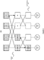
Figure 1 shows an illustration of an exemplary scenario when a deadlock occurs in a middleware machine environment. As shown inFigure 1 , a fat-tree topology 100 in the middleware machine environment allows a mixed communication pattern with two switch-to-switch communication pairs (switch 0 to switch 3, andswitch 3 to switch 6) and two node-to-node communication pairs (node B to node D, and node D to node A). Here, the traffic fromswitch 0 to switch 3 is directed viaswitches switch 3 to switch 6 is directed viaswitches switches switches - As shown in the dashed lines in
Figure 1 , a cycle credit dependency, or a credit loop101, is created when the above mixed communication pattern exists in a fat-tree topology 100. Furthermore, a deadlock can happen when a cyclic credit dependency is created. This does not mean that whenever a cyclic credit dependency is present, there will always be a deadlock. In other words, the creation of a cyclic credit dependency makes the deadlock occurrence possible. For example, when a routing algorithm such as minhop is used, a deadlock may occur in a 3-stage fat-tree with node-to-node and switch-to-switch traffic. This is because minhop is unable to solve a ring of 5 nodes or bigger in a deadlock free manner, and a 3-stage fat-tree may contain a 6-node ring. Thus, there is a need for an algorithm that can provide deadlock free routing in fat-tree topologies when switch-to-switch communication between all switches is present. - Deadlocks can be avoided by using VLs that segment the available physical resources. However, using VLs for implementing deadlock avoidance in fat-trees can be inefficient because the additional VLs can be used for other purposes like quality of service (QoS).
- For example, the LASH algorithm for IB can support full connectivity and deadlock freedom. The LASH algorithm uses VLs to break the
credit loop 101, and provides full connectivity between all the nodes in the fabric. LASH does not exploit the properties of the fat-trees when assigning the paths, thus, allows worse network performance than ordinary fat-tree routing, and, additionally, LASH has a long routing time. DFSSSP is another routing protocol that may be used to support all-to-all switch-to-switch communication in fat-trees. However, DFSSSP does not break credit loops between non-HCA nodes, which means that switch-to-switch communication may not be deadlock free. - Thus, when a deadlock occurs in an interconnection network, the deadlock can prevent communication in part, or all, of the network. Therefore, from the system-wide perspective of an interconnection network, full connectivity supported in a fat-tree topology is preferably deadlock free.
- In accordance with an embodiment of the invention, full connectivity can be supported between the nodes in the middleware machine environment, and deadlock freedom can be achieved for the whole fabric only using a single VL.
-
Figure 2 shows an illustration of providing deadlock free routing between switches in a single-core fat-tree topology in accordance with an embodiment of the invention. As shown inFigure 2 , a single-core fat-tree topology 200 in the middleware machine environment can include a plurality of switches. Furthermore, the middleware machine environment can include a plurality of end-nodes 220, such as server nodes, that connect to the leaf switches 202 in the fat-tree topology 200. - An up/down turn model can be used to provide fat-tree routing in the middleware machine environment. For example, the switches A1 and A2 can have connectivity by going up through X1 or X2. On the other hand, the up/down turn model may not be useful for the communication between switches, e.g. A1 and B1, that do not have a lowest common ancestor.
- In accordance with an embodiment of the invention, an alternative approach can be employed to achieve connectivity between switches that can not establish communication using the up/down turn model. As shown in
Figure 2 , an upside down tree, or a subtree 210 (shown in shadowed area), can be created in the fat-tree topology 200. Thesubtree 210 can have a subtree root node, Sn, or ahub switch 201, which is a leaf switch in the fat-tree topology 200. Full connectivity can be established through thehub switch 201 in the fat-tree topology 200. - Within the
subtree 210, the switches X1 and Y1 can communicate through the subtree root,Sn 201, whereas X1 and X2 can communicate through switch A1. Furthermore, switches external to thesubtree 210 can communicate with other switches in the fat-tree topology 200 through thesubtree 210, which leads to the usage of non-shortest (or suboptimal) paths. A switch in the fabric that cannot reach another switch using the up/down turn model, can first send the packets to thesubtree 210. Then, the packets can be passed down in thesubtree 210 until they reach a switch that has a path to the destination switch. In other words, the packets make a U-turn in thehub switch 201, i.e. a down to up turn followed by a up to down path towards the destination. Thesubtree 210 in the middleware machine environment can localize all the down/up turns in a fabric to a single, deadlock free tree. - For example, when a request is received to route one or more packets from a first switch, e.g. A1, to a second switch, e.g. B2, in the middleware machine environment, the system can first determine whether a routing table associated with the subtree root switch, or the
hub switch 201, contains a path to the second switch, B2. As shown inFigure 2 in dashed lines, thehub switch 201 can connect to the second switch, B2, via a path through B1, Y1 orY2. Then, the path to the second switch, B2, can be inserted into a routing table associated with the first switch, A1. Additionally, in the routing table associated with A1, an output port for switch A2 can set to be the same as the output port for thehub switch 201. - The root of the upside down subtree 210 can be any of the leaf switches. Furthermore, all the switches in the fat-
tree topology 200 can collectively choose a leaf switch for communication, in order to achieve deadlock free full connectivity in the middleware machine environment. - In accordance with an embodiment of the invention, the deadlock freedom can be achieved in the fat-
tree topology 200 by requiring that all U-turns take place only within thesubtree 210, and that any up to down turn will direct the traffic leaving thesubtree 210. Additionally, traffic leaving thesubtree 210 may not be able to circulate back into thesubtree 210, because no U-turn outside of thesubtree 210 is allowed. - Thus, in a single-core fat-
tree 200, there can always be a path that connects from a source switch to ahub switch 201, and connects from thehub switch 201 to every destination switch. Furthermore, the communication scheme for achieving connectivity through a leaf switch in the topology does not change the upward to downward paths between the switches that can reach each other using the fat-tree routing. - Attached is Appendix A that provides further information regarding supporting routing between switches in a middleware machine environment and various aspects of the platform described throughout this disclosure. The information in Appendix A is provided for illustration purposes and should not be construed to limit all of the embodiments of the invention.
- In accordance with an embodiment of the invention, connectivity may not always exist between two switches in a complex multi-core fat-tree, or an irregular fat-tree. A best-effort approach can be employed in these cases to route switch-to-switch communication.
-
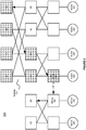
Figure 3 shows an illustration of providing deadlock free routing between switches in a multi-core fat-tree topology in accordance with an embodiment of the invention. As shown inFigure 3 , a multi-core fat-tree topology 300 in the middleware machine environment can include a plurality of switches. Furthermore, the middleware machine environment can include a plurality of end-nodes 320, such as server nodes that connect to the leaf switches in the fat-tree topology 300. - Similarly, an upside down tree, or a subtree 310 (shown in shadowed area), can be created in the fat-
tree topology 300. Thesubtree 310 can have a subtree root node, Sn, or ahub switch 301, which is a leaf switch in the fat-tree topology 300. Unlike inFigure 2 , the subtree root switch or thehub switch 301 may not have paths to all destinations. - Additionally, a
sibling switch 302 can exist in the middleware machine environment and can connect with the subtree root switch, Sn, or thehub switch 301 through ahorizontal link 330. - In one example, a first switch, e.g. B2, can request to route one or more packets to a second switch, e.g. B3, in the middleware machine environment. The
subtree root switch 301 does not have a path connecting to B3, since B3 is located in a separate fat-tree that only connects with the other nodes via a horizontal link. - The system can first check whether the
subtree root switch 301 has asibling switch 302 whose routing table contains a path to B3. Then, the system can set a path to the second switch, B3, on the first switch, B2, and thesubtree root switch 301 through saidsibling switch 302. As a result, the system can be configured to route a packet initiated from switch B2 to switch B3, for example, via Y1 or Y2, B1,subtree root node 301, and its sibling node 302 (shown in dashed lines). - In accordance with an embodiment of the invention, a routing algorithm, i.e. the SFTREE algorithm, can be used to achieve deadlock free full connectivity between the switches. The SFTREE algorithm can include two steps: a first step to find the subtree root Sn, which can be one of the leaf switches, and a second step to perform the switch-to-switch routing.
- The following Algorithm 1 includes pseudo code for finding a subtree root and establishes the subtree.
Algorithm 1 Select a subtree root function Require: Routing table has been generated. Ensure: A subtree root (swroot) is selected. 1: found = false 2: for swleaf = 0 to max_leaf_sw do 3: if found = = true then 4: break 5: end if 6: swroot = swleaf 7: found = true 8: for dst = 1 to max_dst_addr do 9: if swroot.routing_table[dst] = = no_path then 10: found = false 11: break 12: end if 13: end for 14: end for 15: if found = false then 16: swroot = get_leaf (0) 17: end if - Algorithm 1 traverses all the leaf switches in the topology, and for each leaf switch checks whether any of the switch destination addresses are marked as unreachable in its routing table. If all the switch destinations in the routing table are marked as reachable, the first encountered leaf switch is selected as a subtree root switch. Furthermore, there can be as many potential subtrees in a fat-tree as there are leaf switches having full connectivity. Only one of those leaf switches may be selected as the subtree root and there may be only one subtree with a root in this particular leaf switch.
- The following
Algorithm 2 includes pseudo code for performing switch-to-switch routing in the fat-tree topology.Algorithm 2 Switch-to-switch routing functionRequire: Subtree root (swroot) Ensure: Each swsrc reaches each swdst at worst by swroot. 1: if found or swroot.routing_table[dst] ≠ no_path then 2: port = swsrc.routing_table[swroot.addr] 3: swsrc.routing_table[dst] = port 4: get_path_length (swsrc, null, dst, swroot, hops) 5: set_hops (swsrc , hops) 6: return true 7: else if (swsib = get_sibling_sw(swroot) ≠ null then 8: if swsrc.routing_table[swsib.addr] ≠ no_path then 9: if swsib.routing_table[dst] ≠ no_path then 10: port = get_port_to_sibling (swsib) 11: swroot.routing_table[dst] = port 12: hops = get_hops (swsib,dst) 13: set_hops(swroot, hops + 1) 14: hops = 0 15: port = swsrc.routing_table[swsib.addr] 16: swsrc.routing_table[dst] = port 17: get_path_length(swsrc, null, dst, swroot, hops) 18: set_hops(swsrc, hops) 19: return true 20: end if 21: end if 22: end if 23: print 'SW2SW failed for swsrc and swdst .' 24: return false - When the switch-to-switch routing function is called, the first step is to determine whether the routing table of the subtree root (swroot ) contains a path to the destination switch (swdst ) as shown in
Algorithm 2 in line 1. If it does, then the path to the destination switch is inserted into the routing table of the source switch (swsrc ) and the output port for the destination switch is the same as the output port for the path to the subtree root (lines 2-6). Because the switch-to-switch routing function is called for every switch, in the end, all the paths to each unreachable destination switch will converge to the subtree. In other words, the selected subtree root is the new target for all the unreachable destination switches. The down/up turn will take place at the first possible switch located in the subtree, which can be the switch that has an upward path both to the source switch and the destination switch. - The second part of Algorithm 2 (lines 7-24) addresses the cases of complex multi-core or irregular fat trees, where the best-effort approach is employed and the subtree root does not have paths to all the destinations. On the other hand, this second part of
Algorithm 2 may be skipped in a single-core fat-tree, since there can always be a path from the source switch to the subtree root, and the subtree root may have a path to every destination switch. -
Algorithm 2 checks whether the subtree root has a direct neighbor (line 7), to which they are connected through horizontal links as shown inFigure 3 . Next,Algorithm 2 checks whether that neighbor, also called a sibling, has a path to the destination switch (line 8). If the sibling exists and the sibling has a path to the destination switch, a path is set both on the subtree root and the originating source switch to the destination switch through the sibling switch (lines 9-19). In other words, the target for the unreachable destination switch may still be the subtree root, and the subtree root can forward the packets to the destination switch via its sibling which. - The SFTREE Algorithm may fail to find a path between two switches if both previous steps do not return from the function with a true value. For example, this can occur for topologies on which it is not recommended to run the fat-tree routing due to multiple link failures or very irregular connections between the nodes. An example of such a topology can be two fat-trees of different sizes connected to each other in an asymmetrical manner, e.g. from a few middle-stage switches on the larger tree to roots on the smaller one. Using various command-line parameters in OpenSM, a fat-tree routing can be forced to run on these topologies. The SFTREE Algorithm may give suboptimal routing not only in terms of performance, but also in terms of connectivity.
- In accordance with an embodiment of the invention, OpenSM allows every path to be marked with a hop count to the destination. The fat-tree routing algorithm can calculate the number of hops using the switch rankings in the tree. Also, the counting can be done using a simple counter in the main routing function. These counting approaches may be unreliable for the possible zig-zag paths (i.e. paths not following the shortest hop path), when the switch-to-switch routing is totally independent of the main routing done by the fat-tree algorithm.
- A recurrence function for hop calculation, e.g. get_path_length (line 17), can be used during the switch-to-switch routing. This function can iterate over the series of the switches that constitute the path, and when this function reaches the node having a proper hop count towards the destination, this function can write the hop count into the routing tables of the switches on the path.
- Additionally, a subtree root can be selected in such a way that the subnet manager node (the end-node on which the subnet manager is running) is not connected to the switch marked as the subtree root. Thus, the switch-to-switch traffic can be drawn away from the subnet manager, thus not creating a bottleneck in a critical location.
-
Figure 4 illustrates an exemplary flow chart for providing deadlock free routing between switches in a fat-tree topology, in accordance with an embodiment of the invention. As shown inFigure 4 , atstep 401, a middleware machine environment can perform routing for inter-switch traffic in the middleware machine environment using a routing algorithm. Then, atstep 402, the middleware machine environment can select a switch in the middleware machine environment to be a hub switch for inter-switch traffic that can not reach destination using the routing algorithm. Furthermore, atstep 403, the middleware machine environment can update a routing table associated with the hub switch when a path exists between a source switch and a destination switch via the hub switch. -
Figure 5 illustrates an exemplary embodiment of a switch according to the present invention, which may be included in any of the systems described above that supports inter-switch traffic routing in a middleware machine environment and comprises a plurality of switches. Referring toFigure 5 , theexemplary switch 10 may include arouting unit 11, a selectingunit 13 and an updatingunit 14 that are configured in accordance with the principles of the invention as described above. The functional units of theswitch 10, including but not limited tounits Figure 5 each may be combined or separated into sub-units to implement the principles of the invention as described above. Therefore, the description herein may support any possible combination or separation or further definition of the functional blocks described herein. - The
routing unit 11 may perform routing for inter-switch traffic in the middleware machine environment using a first routing algorithm as disclosed above. The selectingunit 13 may select a switch in the middleware machine environment to be a hub switch for inter-switch traffic that can not reach destination using the first routing algorithm. When a path exists between a source switch and a destination switch via the hub switch, the updatingunit 14 may update a routing table associated with the hub switch. - In an exemplary embodiment, the plurality of switches of the system form a fat-tree topology. A leaf switch in the fat-tree topology may be selected by the selecting
unit 13 as the hub switch and the leaf switch can reach a plurality of switch destinations in the fat-tree topology. The first routing algorithm may use an up/down turn model to route the inter-switch traffic in the fat-tree topology. The inter-switch traffic makes down/up turns when the up/down turn model fails, and all down/up turns are localized to a single, deadlock free subtree with the hub switch as a subtree root node, in order to prevent deadlock in the fat-tree topology. - In an exemplary embodiment, the
switch 10 may optionally comprise aniterating unit 12 for iterating through a plurality of leaf switches in the fat-tree topology in order to find one or more leaf switches that can reach a plurality of switches destinations in the fat-tree topology. Thus, the selectingunit 13 may select the hub switch from the one or more leaf switches. - In an exemplary embodiment, the
switch 10 may further comprise achecking unit 15. The checkingunit 15 may check whether the hub switch has a sibling switch, and whether a routing table associated with the sibling contains a path to the destination switch when the path does not exist. - In an exemplary embodiment, the
switch 10 may further comprise apath setting unit 16. When the sibling switch exists and the routing table associated with the sibling switch contains a path to the destination switch, thepath setting unit 16 may set a path to the destination switch on the source switch and the subtree root switch through the sibling switch. - In an exemplary embodiment, the
switch 10 may further comprise aport setting unit 17 for setting an output port for the destination switch to be same as an output port for the hub switch. - The present invention may be conveniently implemented using one or more conventional general purpose or specialized digital computer, computing device, machine, or microprocessor, including one or more processors, memory and/or computer readable storage media programmed according to the teachings of the present disclosure. Appropriate software coding can readily be prepared by skilled programmers based on the teachings of the present disclosure, as will be apparent to those skilled in the software art.
- In some embodiments, the present invention includes a computer program product which is a storage medium or computer readable medium (media) having instructions stored thereon/in which can be used to program a computer to perform any of the processes of the present invention. The storage medium can include, but is not limited to, any type of disk including floppy disks, optical discs, DVD, CD-ROMs, microdrive, and magneto-optical disks, ROMs, RAMs, EPROMs, EEPROMs, DRAMs, VRAMs, flash memory devices, magnetic or optical cards, nanosystems (including molecular memory ICs), or any type of media or device suitable for storing instructions and/or data.
- The foregoing description of the present invention has been provided for the purposes of illustration and description. It is not intended to be exhaustive or to limit the invention to the precise forms disclosed. Many modifications and variations will be apparent to the practitioner skilled in the art. The variations may include any combination of the disclosed features and/or elements. The embodiments were chosen and described in order to best explain the principles of the invention and its practical application, thereby enabling others skilled in the art to understand the invention for various embodiments and with various modifications that are suited to the particular use contemplated. It is intended that the scope of the invention be defined by the claims as appended.
- The following is a proof that demonstrates that the SFTREE algorithm is deadlock free. The proof also contains exemplary definitions of the related terms.
- Definition 1. By switch sn, we mean a switch with a rank n. Root switches have rank n=0.
-
Definition 2. By a downward channel we mean a link between s n-1 and sn , where the traffic is flowing from sn-1 to sn. By an upward channel we mean a link between sn and sn-1, where the traffic is flowing from sn to s n-1 . -
Definition 3. A path is defined as a series of switches connected by channels. It begins with a source switch and ends with a destination switch. - Definition.4. A U-turn is a turn where a downward channel is followed by an upward channel.
-
Definition 5. A channel dependency between channel ci and channel cj occurs when a packet holding channel ci requests the use of channel cj . -
Definition 6. A channel dependency graph G = (V, E) is a directed graph where the vertices V are the channels of the network N, and the edges E are the pairs of channels (ci , cj ) such that there exists a (channel) dependency from ci to cj . -
Definition 7. By a subtree we mean a logical upside down tree structure within a fat-tree that converges to a single leaf switch s, is the single root of the subtree. A subtree expands from its root and its leaves are all the top-level switches in the fat-tree. Any upward to downward turn will leave the subtree structure. - The following theorem states the sufficient condition for deadlock freedom of a routing function.
- THEOREM 1. A deterministic routing function R for network N is deadlock free if and only if there are no cycles in the channel dependency graph G.
- Next, the lemmas followed by the deadlock freedom theorem of the SFTREE algorithm can be provided.
-
LEMMA 8. There exists at least one subtree within a fat-tree that allows full switch-to-switch connectivity using only U-turns within that subtree. - PROOF. In a fat-tree, from any leaf we can reach any other node (including all the switches) in the fabric using an up/down path or a horizontal sibling path. This is because every end-node can communicate with every other end-node, and because end-nodes are directly connected to the leaf switches, it follows that leaf switches are able to reach any other node in the topology. Consequently, if it contains no link faults, any leaf switch can act as the root of the subtree.
-
LEMMA 9. There can be an unlimited number of U-turns within a single subtree without introducing a deadlock. - PROOF. A subtree is a logical tree structure and two types of turns can take place within it: U-turns, i.e. downward to upward turns, and ordinary upward to downward turns. The U-turns cannot take place at the top switches in a subtree (and fat-tree) because these switches have no output upward ports. Any upward to downward turn will leave the subtree according to
Definition 7. - Because a subtree is a connected graph without any cycles, it is deadlock free by itself. Any deadlock must involve U-turns external to the subtree since a U-turn is followed by an upward to downward turn leaving the subtree. All the traffic going through an up/down turn originating in the subtree will leave the subtree when the turn is made and follow only the downward channels to the destination. Such a dependency can never enter the subtree again and can never reach any other U-turn, and so, cannot form any cycle.
-
THEOREM 2. The SFTREE algorithm using the subtree method is deadlock free. - PROOF. Following
Lemma 8 andLemma 9, a deadlock in a fat-tree can only occur if there are U-turns outside the subtree. Such a situation cannot happen due to the design of the SFTREE algorithm where all U-turns take place within a subtree. The traffic leaving a subtree will not circle back to it because once it leaves the subtree, it is forwarded to the destination through downward channels only, and it is consumed, thus, no cyclic credit dependencies will occur in the topology.
Claims (13)
- A method for supporting traffic routing between a plurality of switches in a middleware machine environment in a fat tree topology and operating on one or more microprocessors, comprising:using a routing algorithm to route inter-switch traffic from a source switch to a destination switch in the middleware machine environment, wherein the middleware machine environment includes a plurality of leaf switches (202), each leaf switch connected to an end node (220);determining that the destination switch is unreachable to the inter-switch traffic being routed using the algorithm;traversing though the routing tables of the plurality of leaf switches to determine that all switch destinations in the routing table of a particular leaf switch are marked as reachable for the particular leaf switch;selecting the particular leaf switch in the middleware machine environment to be a hub switch (201) for inter-switch traffic that can not reach its destination using the routing algorithm; andupdating a routing table associated with the source switch when a path exists between the source switch and the destination switch via the hub switch.
- The method of Claim 1 further comprising:
using an up/down turn model in the routing algorithm to route the inter-switch traffic in the fat-tree topology. - The method of Claim 2 further comprising:
allowing the inter-switch traffic to make down/up turns when the up/down turn model fails, and localizing all down/up turns to a single, deadlock free subtree with the hub switch as a subtree root node, in order to prevent deadlock in the fat-tree topology. - The method of any one of the preceding claims, further comprising: checking whether the hub switch has a sibling switch and whether a routing table associated with said sibling contains a path to the destination switch when said path does not exist.
- The method of Claim 4 further comprising:
when said sibling switch exists and the routing table associated with said sibling switch contains a path to the destination switch, setting a path to the destination switch on the source switch and the subtree root switch through said sibling switch. - The method of any one of the preceding claims, further comprising: allowing an output port for the destination switch to be same as an output port for the hub switch.
- The method of any one of the preceding claims, further comprising: using a recurrence function for hop calculation in inter-switch routing, wherein the recurrence function iterates over one or more switches that constitute the path.
- A computer program product comprising program instructions that when executed by one or more computer systems cause the one or more systems to perform all the steps of the method of any of the preceding claims.
- A computer program product comprising a machine readable storage medium having the computer program product of Claim 8 stored thereon.
- A system for supporting inter-switch traffic routing in a middleware machine environment, comprising:
a plurality of switches in a fat tree topology running on one or more microprocessors, wherein the plurality of switches operates to perform the steps of:using a routing algorithm to route inter-switch traffic from a source switch to a destination switch in the middleware machine environment using a routing algorithm, wherein the middleware machine environment includes a plurality of leaf switches, each leaf switch connected to an end node;determining that the destination switch is unreachable to the inter-switch traffic being routed using the algorithm;traversing though the routing tables of the plurality of leaf switches to determine that all switch destinations in the routing table of a particular leaf switch are marked as reachable for the particular leaf switch.selecting the particular leaf switch in the middleware machine environment to be a hub switch for inter-switch traffic that can not reach its destination using the routing algorithm; andupdating a routing table associated with the source switch when a path exists between the source switch and the destination switch via the hub switch. - The system of Claim 10, wherein the routing algorithm includes using an up/down turn model to route the inter-switch traffic in the fat-tree topology.
- The system of Claim 11, configured that the inter-switch traffic makes down/up turns when the up/down turn model fails, and all down/up turns are localized to a single, deadlock free subtree with the hub switch as a subtree root node, in order to prevent deadlock in the fat-tree topology.
- The system of any one of Claims 10 to 12, further configured to check whether the hub switch has a sibling switch and whether a routing table associated with said sibling contains a path to the destination switch when said path does not exist.
Applications Claiming Priority (3)
| Application Number | Priority Date | Filing Date | Title |
|---|---|---|---|
| US201161557722P | 2011-11-09 | 2011-11-09 | |
| US13/653,303 US9014201B2 (en) | 2011-11-09 | 2012-10-16 | System and method for providing deadlock free routing between switches in a fat-tree topology |
| PCT/US2012/064479 WO2013071130A1 (en) | 2011-11-09 | 2012-11-09 | System and method for providing deadlock free routing between switches in a fat-tree topology |
Publications (2)
| Publication Number | Publication Date |
|---|---|
| EP2777229A1 EP2777229A1 (en) | 2014-09-17 |
| EP2777229B1 true EP2777229B1 (en) | 2019-06-05 |
Family
ID=48223652
Family Applications (1)
| Application Number | Title | Priority Date | Filing Date |
|---|---|---|---|
| EP12798497.9A Active EP2777229B1 (en) | 2011-11-09 | 2012-11-09 | System and method for providing deadlock free routing between switches in a fat-tree topology |
Country Status (6)
| Country | Link |
|---|---|
| US (1) | US9014201B2 (en) |
| EP (1) | EP2777229B1 (en) |
| JP (1) | JP6018217B2 (en) |
| CN (1) | CN103907322B (en) |
| IN (1) | IN2014CN02131A (en) |
| WO (1) | WO2013071130A1 (en) |
Families Citing this family (23)
| Publication number | Priority date | Publication date | Assignee | Title |
|---|---|---|---|---|
| US9130858B2 (en) * | 2012-08-29 | 2015-09-08 | Oracle International Corporation | System and method for supporting discovery and routing degraded fat-trees in a middleware machine environment |
| US10051054B2 (en) | 2013-03-15 | 2018-08-14 | Oracle International Corporation | System and method for efficient virtualization in lossless interconnection networks |
| US9990221B2 (en) | 2013-03-15 | 2018-06-05 | Oracle International Corporation | System and method for providing an infiniband SR-IOV vSwitch architecture for a high performance cloud computing environment |
| US9160666B2 (en) * | 2013-05-20 | 2015-10-13 | Telefonaktiebolaget L M Ericsson (Publ) | Encoding a payload hash in the DA-MAC to facilitate elastic chaining of packet processing elements |
| US9577956B2 (en) | 2013-07-29 | 2017-02-21 | Oracle International Corporation | System and method for supporting multi-homed fat-tree routing in a middleware machine environment |
| US9294385B2 (en) * | 2014-03-03 | 2016-03-22 | International Business Machines Corporation | Deadlock-free routing in fat tree networks |
| US10397105B2 (en) | 2014-03-26 | 2019-08-27 | Oracle International Corporation | System and method for scalable multi-homed routing for vSwitch based HCA virtualization |
| US9876737B2 (en) | 2014-07-11 | 2018-01-23 | Oracle International Corporation | System and method for supporting efficient load-balancing in a high performance computing (HPC) environment |
| US10198288B2 (en) | 2014-10-30 | 2019-02-05 | Oracle International Corporation | System and method for providing a dynamic cloud with subnet administration (SA) query caching |
| JP6653699B2 (en) * | 2014-10-31 | 2020-02-26 | オラクル・インターナショナル・コーポレイション | System and method for supporting partition-aware routing in a multi-tenant cluster environment |
| FR3036239B1 (en) * | 2015-05-13 | 2018-07-06 | Bull Sas | NETWORK OF EQUIPMENTS INTERCONNECTED BY SWITCHES INTEGRATING ROUTING TABLES |
| JP6492977B2 (en) * | 2015-06-01 | 2019-04-03 | 富士通株式会社 | Parallel computing device, parallel computing system, node allocation program, and node allocation method |
| US10187310B2 (en) | 2015-10-13 | 2019-01-22 | Oracle International Corporation | System and method for efficient network isolation and load balancing in a multi-tenant cluster environment |
| US10284465B2 (en) | 2015-12-28 | 2019-05-07 | Mellanox Technologies Tlv Ltd. | Efficient algorithmic forwarding in fat-tree networks |
| CN105471749B (en) * | 2016-01-21 | 2018-06-26 | 中国人民解放军国防科学技术大学 | The exponent number flexibly extensive interconnection network topological structure of low diameter and method for routing |
| US10594505B2 (en) | 2016-01-27 | 2020-03-17 | Quanta Computer Inc. | System and method for avoiding deadlock in transmission of broadcast traffic in a server system |
| JP6623939B2 (en) * | 2016-06-06 | 2019-12-25 | 富士通株式会社 | Information processing apparatus, communication procedure determination method, and communication program |
| US10630590B2 (en) * | 2016-07-14 | 2020-04-21 | Mellanox Technologies Tlv Ltd. | Credit loop deadlock detection and recovery in arbitrary topology networks |
| US10425324B2 (en) | 2017-08-17 | 2019-09-24 | Fabriscale Technologies AS | Method of computing balanced routing paths in fat-trees |
| CN111526113B (en) | 2019-02-02 | 2023-05-30 | 中兴通讯股份有限公司 | Protocol processing method and device and storage medium |
| CN112019365A (en) * | 2019-05-31 | 2020-12-01 | 华为技术有限公司 | Method and device for determining port attribute |
| US11108679B2 (en) * | 2019-08-08 | 2021-08-31 | Mellanox Technologies Tlv Ltd. | Producing deadlock-free routes in lossless cartesian topologies with minimal number of virtual lanes |
| US11425027B2 (en) | 2020-11-01 | 2022-08-23 | Mellanox Technologies, Ltd. | Turn-based deadlock-free routing in a Cartesian topology |
Family Cites Families (3)
| Publication number | Priority date | Publication date | Assignee | Title |
|---|---|---|---|---|
| US6625256B1 (en) * | 2001-04-27 | 2003-09-23 | Cisco Technology, Inc. | Failover mechanisms for remote networked phones |
| US7532583B2 (en) * | 2006-05-30 | 2009-05-12 | International Business Machines Corporation | Method for integrating downstream performance and resource usage statistics into load balancing weights |
| JP5430481B2 (en) * | 2010-04-12 | 2014-02-26 | 三菱電機株式会社 | Gateway and terminal |
-
2012
- 2012-10-16 US US13/653,303 patent/US9014201B2/en active Active
- 2012-11-09 WO PCT/US2012/064479 patent/WO2013071130A1/en active Application Filing
- 2012-11-09 JP JP2014541332A patent/JP6018217B2/en active Active
- 2012-11-09 CN CN201280052888.2A patent/CN103907322B/en active Active
- 2012-11-09 EP EP12798497.9A patent/EP2777229B1/en active Active
-
2014
- 2014-03-19 IN IN2131CHN2014 patent/IN2014CN02131A/en unknown
Non-Patent Citations (1)
| Title |
|---|
| None * |
Also Published As
| Publication number | Publication date |
|---|---|
| US20130114620A1 (en) | 2013-05-09 |
| CN103907322A (en) | 2014-07-02 |
| US9014201B2 (en) | 2015-04-21 |
| CN103907322B (en) | 2017-01-18 |
| WO2013071130A1 (en) | 2013-05-16 |
| JP2014533071A (en) | 2014-12-08 |
| JP6018217B2 (en) | 2016-11-02 |
| IN2014CN02131A (en) | 2015-05-29 |
| EP2777229A1 (en) | 2014-09-17 |
Similar Documents
| Publication | Publication Date | Title |
|---|---|---|
| EP2777229B1 (en) | System and method for providing deadlock free routing between switches in a fat-tree topology | |
| EP2891286B1 (en) | System and method for supporting discovery and routing degraded fat-trees in a middleware machine environment | |
| US9577956B2 (en) | System and method for supporting multi-homed fat-tree routing in a middleware machine environment | |
| US11936515B2 (en) | System and method for efficient network reconfiguration in fat-trees | |
| JP6267367B2 (en) | Packet routing method in distributed direct interconnection network | |
| US11729048B2 (en) | System and method for efficient network reconfiguration in fat-trees | |
| EP2617165B1 (en) | System and method for providing ethernet over infiniband virtual hub scalability in a middleware machine environment | |
| US11659436B2 (en) | Scalable reachability for movable destinations attached to a leaf-spine switching architecture | |
| Bogdanski | Optimized routing for fat-tree topologies | |
| Bogdanski et al. | sFtree: a fully connected and deadlock-free switch-to-switch routing algorithm for fat-trees | |
| Reinemo et al. | Multi-homed fat-tree routing with InfiniBand | |
| Bogdanski et al. | Deadlock-Free Switch-to-Switch Routing Algorithm for Fat-Trees |
Legal Events
| Date | Code | Title | Description |
|---|---|---|---|
| PUAI | Public reference made under article 153(3) epc to a published international application that has entered the european phase |
Free format text: ORIGINAL CODE: 0009012 |
|
| 17P | Request for examination filed |
Effective date: 20140602 |
|
| AK | Designated contracting states |
Kind code of ref document: A1 Designated state(s): AL AT BE BG CH CY CZ DE DK EE ES FI FR GB GR HR HU IE IS IT LI LT LU LV MC MK MT NL NO PL PT RO RS SE SI SK SM TR |
|
| RIN1 | Information on inventor provided before grant (corrected) |
Inventor name: BOGDANSKI, BARTOSZ |
|
| DAX | Request for extension of the european patent (deleted) | ||
| STAA | Information on the status of an ep patent application or granted ep patent |
Free format text: STATUS: EXAMINATION IS IN PROGRESS |
|
| 17Q | First examination report despatched |
Effective date: 20180416 |
|
| REG | Reference to a national code |
Ref country code: DE Ref legal event code: R079 Ref document number: 602012060751 Country of ref document: DE Free format text: PREVIOUS MAIN CLASS: H04L0012753000 Ipc: H04L0012707000 |
|
| GRAP | Despatch of communication of intention to grant a patent |
Free format text: ORIGINAL CODE: EPIDOSNIGR1 |
|
| STAA | Information on the status of an ep patent application or granted ep patent |
Free format text: STATUS: GRANT OF PATENT IS INTENDED |
|
| RIC1 | Information provided on ipc code assigned before grant |
Ipc: H04L 12/753 20130101ALI20181129BHEP Ipc: H04L 12/707 20130101AFI20181129BHEP Ipc: H04L 12/933 20130101ALI20181129BHEP |
|
| INTG | Intention to grant announced |
Effective date: 20181220 |
|
| RIN1 | Information on inventor provided before grant (corrected) |
Inventor name: BOGDANSKI, BARTOSZ |
|
| GRAS | Grant fee paid |
Free format text: ORIGINAL CODE: EPIDOSNIGR3 |
|
| GRAA | (expected) grant |
Free format text: ORIGINAL CODE: 0009210 |
|
| STAA | Information on the status of an ep patent application or granted ep patent |
Free format text: STATUS: THE PATENT HAS BEEN GRANTED |
|
| AK | Designated contracting states |
Kind code of ref document: B1 Designated state(s): AL AT BE BG CH CY CZ DE DK EE ES FI FR GB GR HR HU IE IS IT LI LT LU LV MC MK MT NL NO PL PT RO RS SE SI SK SM TR |
|
| REG | Reference to a national code |
Ref country code: GB Ref legal event code: FG4D |
|
| REG | Reference to a national code |
Ref country code: CH Ref legal event code: EP |
|
| REG | Reference to a national code |
Ref country code: AT Ref legal event code: REF Ref document number: 1141113 Country of ref document: AT Kind code of ref document: T Effective date: 20190615 |
|
| REG | Reference to a national code |
Ref country code: IE Ref legal event code: FG4D |
|
| REG | Reference to a national code |
Ref country code: DE Ref legal event code: R096 Ref document number: 602012060751 Country of ref document: DE |
|
| REG | Reference to a national code |
Ref country code: NL Ref legal event code: MP Effective date: 20190605 |
|
| REG | Reference to a national code |
Ref country code: LT Ref legal event code: MG4D |
|
| PG25 | Lapsed in a contracting state [announced via postgrant information from national office to epo] |
Ref country code: AL Free format text: LAPSE BECAUSE OF FAILURE TO SUBMIT A TRANSLATION OF THE DESCRIPTION OR TO PAY THE FEE WITHIN THE PRESCRIBED TIME-LIMIT Effective date: 20190605 Ref country code: SE Free format text: LAPSE BECAUSE OF FAILURE TO SUBMIT A TRANSLATION OF THE DESCRIPTION OR TO PAY THE FEE WITHIN THE PRESCRIBED TIME-LIMIT Effective date: 20190605 Ref country code: FI Free format text: LAPSE BECAUSE OF FAILURE TO SUBMIT A TRANSLATION OF THE DESCRIPTION OR TO PAY THE FEE WITHIN THE PRESCRIBED TIME-LIMIT Effective date: 20190605 Ref country code: HR Free format text: LAPSE BECAUSE OF FAILURE TO SUBMIT A TRANSLATION OF THE DESCRIPTION OR TO PAY THE FEE WITHIN THE PRESCRIBED TIME-LIMIT Effective date: 20190605 Ref country code: NO Free format text: LAPSE BECAUSE OF FAILURE TO SUBMIT A TRANSLATION OF THE DESCRIPTION OR TO PAY THE FEE WITHIN THE PRESCRIBED TIME-LIMIT Effective date: 20190905 Ref country code: LT Free format text: LAPSE BECAUSE OF FAILURE TO SUBMIT A TRANSLATION OF THE DESCRIPTION OR TO PAY THE FEE WITHIN THE PRESCRIBED TIME-LIMIT Effective date: 20190605 Ref country code: ES Free format text: LAPSE BECAUSE OF FAILURE TO SUBMIT A TRANSLATION OF THE DESCRIPTION OR TO PAY THE FEE WITHIN THE PRESCRIBED TIME-LIMIT Effective date: 20190605 |
|
| PG25 | Lapsed in a contracting state [announced via postgrant information from national office to epo] |
Ref country code: RS Free format text: LAPSE BECAUSE OF FAILURE TO SUBMIT A TRANSLATION OF THE DESCRIPTION OR TO PAY THE FEE WITHIN THE PRESCRIBED TIME-LIMIT Effective date: 20190605 Ref country code: BG Free format text: LAPSE BECAUSE OF FAILURE TO SUBMIT A TRANSLATION OF THE DESCRIPTION OR TO PAY THE FEE WITHIN THE PRESCRIBED TIME-LIMIT Effective date: 20190905 Ref country code: GR Free format text: LAPSE BECAUSE OF FAILURE TO SUBMIT A TRANSLATION OF THE DESCRIPTION OR TO PAY THE FEE WITHIN THE PRESCRIBED TIME-LIMIT Effective date: 20190906 Ref country code: LV Free format text: LAPSE BECAUSE OF FAILURE TO SUBMIT A TRANSLATION OF THE DESCRIPTION OR TO PAY THE FEE WITHIN THE PRESCRIBED TIME-LIMIT Effective date: 20190605 |
|
| REG | Reference to a national code |
Ref country code: AT Ref legal event code: MK05 Ref document number: 1141113 Country of ref document: AT Kind code of ref document: T Effective date: 20190605 |
|
| PG25 | Lapsed in a contracting state [announced via postgrant information from national office to epo] |
Ref country code: NL Free format text: LAPSE BECAUSE OF FAILURE TO SUBMIT A TRANSLATION OF THE DESCRIPTION OR TO PAY THE FEE WITHIN THE PRESCRIBED TIME-LIMIT Effective date: 20190605 Ref country code: EE Free format text: LAPSE BECAUSE OF FAILURE TO SUBMIT A TRANSLATION OF THE DESCRIPTION OR TO PAY THE FEE WITHIN THE PRESCRIBED TIME-LIMIT Effective date: 20190605 Ref country code: AT Free format text: LAPSE BECAUSE OF FAILURE TO SUBMIT A TRANSLATION OF THE DESCRIPTION OR TO PAY THE FEE WITHIN THE PRESCRIBED TIME-LIMIT Effective date: 20190605 Ref country code: SK Free format text: LAPSE BECAUSE OF FAILURE TO SUBMIT A TRANSLATION OF THE DESCRIPTION OR TO PAY THE FEE WITHIN THE PRESCRIBED TIME-LIMIT Effective date: 20190605 Ref country code: RO Free format text: LAPSE BECAUSE OF FAILURE TO SUBMIT A TRANSLATION OF THE DESCRIPTION OR TO PAY THE FEE WITHIN THE PRESCRIBED TIME-LIMIT Effective date: 20190605 Ref country code: CZ Free format text: LAPSE BECAUSE OF FAILURE TO SUBMIT A TRANSLATION OF THE DESCRIPTION OR TO PAY THE FEE WITHIN THE PRESCRIBED TIME-LIMIT Effective date: 20190605 Ref country code: PT Free format text: LAPSE BECAUSE OF FAILURE TO SUBMIT A TRANSLATION OF THE DESCRIPTION OR TO PAY THE FEE WITHIN THE PRESCRIBED TIME-LIMIT Effective date: 20191007 |
|
| PG25 | Lapsed in a contracting state [announced via postgrant information from national office to epo] |
Ref country code: IS Free format text: LAPSE BECAUSE OF FAILURE TO SUBMIT A TRANSLATION OF THE DESCRIPTION OR TO PAY THE FEE WITHIN THE PRESCRIBED TIME-LIMIT Effective date: 20191005 Ref country code: IT Free format text: LAPSE BECAUSE OF FAILURE TO SUBMIT A TRANSLATION OF THE DESCRIPTION OR TO PAY THE FEE WITHIN THE PRESCRIBED TIME-LIMIT Effective date: 20190605 Ref country code: SM Free format text: LAPSE BECAUSE OF FAILURE TO SUBMIT A TRANSLATION OF THE DESCRIPTION OR TO PAY THE FEE WITHIN THE PRESCRIBED TIME-LIMIT Effective date: 20190605 |
|
| REG | Reference to a national code |
Ref country code: DE Ref legal event code: R097 Ref document number: 602012060751 Country of ref document: DE |
|
| PG25 | Lapsed in a contracting state [announced via postgrant information from national office to epo] |
Ref country code: TR Free format text: LAPSE BECAUSE OF FAILURE TO SUBMIT A TRANSLATION OF THE DESCRIPTION OR TO PAY THE FEE WITHIN THE PRESCRIBED TIME-LIMIT Effective date: 20190605 |
|
| PLBE | No opposition filed within time limit |
Free format text: ORIGINAL CODE: 0009261 |
|
| STAA | Information on the status of an ep patent application or granted ep patent |
Free format text: STATUS: NO OPPOSITION FILED WITHIN TIME LIMIT |
|
| PG25 | Lapsed in a contracting state [announced via postgrant information from national office to epo] |
Ref country code: DK Free format text: LAPSE BECAUSE OF FAILURE TO SUBMIT A TRANSLATION OF THE DESCRIPTION OR TO PAY THE FEE WITHIN THE PRESCRIBED TIME-LIMIT Effective date: 20190605 Ref country code: PL Free format text: LAPSE BECAUSE OF FAILURE TO SUBMIT A TRANSLATION OF THE DESCRIPTION OR TO PAY THE FEE WITHIN THE PRESCRIBED TIME-LIMIT Effective date: 20190605 |
|
| 26N | No opposition filed |
Effective date: 20200306 |
|
| PG25 | Lapsed in a contracting state [announced via postgrant information from national office to epo] |
Ref country code: SI Free format text: LAPSE BECAUSE OF FAILURE TO SUBMIT A TRANSLATION OF THE DESCRIPTION OR TO PAY THE FEE WITHIN THE PRESCRIBED TIME-LIMIT Effective date: 20190605 |
|
| REG | Reference to a national code |
Ref country code: CH Ref legal event code: PL |
|
| PG25 | Lapsed in a contracting state [announced via postgrant information from national office to epo] |
Ref country code: CH Free format text: LAPSE BECAUSE OF NON-PAYMENT OF DUE FEES Effective date: 20191130 Ref country code: LU Free format text: LAPSE BECAUSE OF NON-PAYMENT OF DUE FEES Effective date: 20191109 Ref country code: LI Free format text: LAPSE BECAUSE OF NON-PAYMENT OF DUE FEES Effective date: 20191130 Ref country code: MC Free format text: LAPSE BECAUSE OF FAILURE TO SUBMIT A TRANSLATION OF THE DESCRIPTION OR TO PAY THE FEE WITHIN THE PRESCRIBED TIME-LIMIT Effective date: 20190605 |
|
| REG | Reference to a national code |
Ref country code: BE Ref legal event code: MM Effective date: 20191130 |
|
| PG25 | Lapsed in a contracting state [announced via postgrant information from national office to epo] |
Ref country code: FR Free format text: LAPSE BECAUSE OF NON-PAYMENT OF DUE FEES Effective date: 20191130 Ref country code: IE Free format text: LAPSE BECAUSE OF NON-PAYMENT OF DUE FEES Effective date: 20191109 |
|
| PG25 | Lapsed in a contracting state [announced via postgrant information from national office to epo] |
Ref country code: BE Free format text: LAPSE BECAUSE OF NON-PAYMENT OF DUE FEES Effective date: 20191130 |
|
| PG25 | Lapsed in a contracting state [announced via postgrant information from national office to epo] |
Ref country code: CY Free format text: LAPSE BECAUSE OF FAILURE TO SUBMIT A TRANSLATION OF THE DESCRIPTION OR TO PAY THE FEE WITHIN THE PRESCRIBED TIME-LIMIT Effective date: 20190605 |
|
| PG25 | Lapsed in a contracting state [announced via postgrant information from national office to epo] |
Ref country code: MT Free format text: LAPSE BECAUSE OF FAILURE TO SUBMIT A TRANSLATION OF THE DESCRIPTION OR TO PAY THE FEE WITHIN THE PRESCRIBED TIME-LIMIT Effective date: 20190605 Ref country code: HU Free format text: LAPSE BECAUSE OF FAILURE TO SUBMIT A TRANSLATION OF THE DESCRIPTION OR TO PAY THE FEE WITHIN THE PRESCRIBED TIME-LIMIT; INVALID AB INITIO Effective date: 20121109 |
|
| REG | Reference to a national code |
Ref country code: DE Ref legal event code: R079 Ref document number: 602012060751 Country of ref document: DE Free format text: PREVIOUS MAIN CLASS: H04L0012707000 Ipc: H04L0045240000 |
|
| PG25 | Lapsed in a contracting state [announced via postgrant information from national office to epo] |
Ref country code: MK Free format text: LAPSE BECAUSE OF FAILURE TO SUBMIT A TRANSLATION OF THE DESCRIPTION OR TO PAY THE FEE WITHIN THE PRESCRIBED TIME-LIMIT Effective date: 20190605 |
|
| P01 | Opt-out of the competence of the unified patent court (upc) registered |
Effective date: 20230522 |
|
| PGFP | Annual fee paid to national office [announced via postgrant information from national office to epo] |
Ref country code: GB Payment date: 20231006 Year of fee payment: 12 |
|
| PGFP | Annual fee paid to national office [announced via postgrant information from national office to epo] |
Ref country code: DE Payment date: 20230929 Year of fee payment: 12 |