EP2770539A1 - Electronic management system for electricity generating cells, electricity generating system and method for electronically managing energy flow - Google Patents
Electronic management system for electricity generating cells, electricity generating system and method for electronically managing energy flow Download PDFInfo
- Publication number
- EP2770539A1 EP2770539A1 EP13290035.8A EP13290035A EP2770539A1 EP 2770539 A1 EP2770539 A1 EP 2770539A1 EP 13290035 A EP13290035 A EP 13290035A EP 2770539 A1 EP2770539 A1 EP 2770539A1
- Authority
- EP
- European Patent Office
- Prior art keywords
- energy
- cells
- outputs
- electricity generating
- converters
- Prior art date
- Legal status (The legal status is an assumption and is not a legal conclusion. Google has not performed a legal analysis and makes no representation as to the accuracy of the status listed.)
- Withdrawn
Links
- 230000005611 electricity Effects 0.000 title claims abstract description 62
- 238000000034 method Methods 0.000 title claims description 15
- 230000003068 static effect Effects 0.000 claims abstract description 31
- 238000006243 chemical reaction Methods 0.000 claims description 8
- 230000008859 change Effects 0.000 claims description 5
- 238000001514 detection method Methods 0.000 claims description 5
- 238000005516 engineering process Methods 0.000 claims description 3
- 230000001747 exhibiting effect Effects 0.000 claims description 3
- 230000001965 increasing effect Effects 0.000 description 8
- 230000006870 function Effects 0.000 description 6
- 238000012545 processing Methods 0.000 description 5
- 230000008901 benefit Effects 0.000 description 4
- 230000007613 environmental effect Effects 0.000 description 4
- 239000000463 material Substances 0.000 description 4
- 239000002800 charge carrier Substances 0.000 description 3
- 230000000694 effects Effects 0.000 description 3
- 239000000446 fuel Substances 0.000 description 2
- 238000003306 harvesting Methods 0.000 description 2
- 238000009434 installation Methods 0.000 description 2
- 238000005457 optimization Methods 0.000 description 2
- 230000036961 partial effect Effects 0.000 description 2
- 230000008569 process Effects 0.000 description 2
- 230000009467 reduction Effects 0.000 description 2
- 238000003860 storage Methods 0.000 description 2
- 230000000153 supplemental effect Effects 0.000 description 2
- 241000112598 Pseudoblennius percoides Species 0.000 description 1
- 230000003044 adaptive effect Effects 0.000 description 1
- 230000032683 aging Effects 0.000 description 1
- 238000013459 approach Methods 0.000 description 1
- 230000000903 blocking effect Effects 0.000 description 1
- 238000010276 construction Methods 0.000 description 1
- 230000003247 decreasing effect Effects 0.000 description 1
- 230000001419 dependent effect Effects 0.000 description 1
- 239000000428 dust Substances 0.000 description 1
- 230000004064 dysfunction Effects 0.000 description 1
- 230000002708 enhancing effect Effects 0.000 description 1
- 210000003608 fece Anatomy 0.000 description 1
- 238000005286 illumination Methods 0.000 description 1
- 239000011147 inorganic material Substances 0.000 description 1
- 229910010272 inorganic material Inorganic materials 0.000 description 1
- 230000001788 irregular Effects 0.000 description 1
- 230000000670 limiting effect Effects 0.000 description 1
- 238000012423 maintenance Methods 0.000 description 1
- 230000007257 malfunction Effects 0.000 description 1
- 238000004519 manufacturing process Methods 0.000 description 1
- 239000011159 matrix material Substances 0.000 description 1
- 238000005259 measurement Methods 0.000 description 1
- 230000000116 mitigating effect Effects 0.000 description 1
- 238000012544 monitoring process Methods 0.000 description 1
- 239000011368 organic material Substances 0.000 description 1
- 238000011176 pooling Methods 0.000 description 1
- 238000010248 power generation Methods 0.000 description 1
- 230000002829 reductive effect Effects 0.000 description 1
- 230000004044 response Effects 0.000 description 1
- 230000000630 rising effect Effects 0.000 description 1
- 239000004065 semiconductor Substances 0.000 description 1
- 230000003595 spectral effect Effects 0.000 description 1
- 239000000758 substrate Substances 0.000 description 1
Images


Classifications
-
- H—ELECTRICITY
- H01—ELECTRIC ELEMENTS
- H01L—SEMICONDUCTOR DEVICES NOT COVERED BY CLASS H10
- H01L31/00—Semiconductor devices sensitive to infrared radiation, light, electromagnetic radiation of shorter wavelength or corpuscular radiation and specially adapted either for the conversion of the energy of such radiation into electrical energy or for the control of electrical energy by such radiation; Processes or apparatus specially adapted for the manufacture or treatment thereof or of parts thereof; Details thereof
- H01L31/02—Details
- H01L31/02016—Circuit arrangements of general character for the devices
- H01L31/02019—Circuit arrangements of general character for the devices for devices characterised by at least one potential jump barrier or surface barrier
- H01L31/02021—Circuit arrangements of general character for the devices for devices characterised by at least one potential jump barrier or surface barrier for solar cells
-
- H02J3/383—
-
- Y—GENERAL TAGGING OF NEW TECHNOLOGICAL DEVELOPMENTS; GENERAL TAGGING OF CROSS-SECTIONAL TECHNOLOGIES SPANNING OVER SEVERAL SECTIONS OF THE IPC; TECHNICAL SUBJECTS COVERED BY FORMER USPC CROSS-REFERENCE ART COLLECTIONS [XRACs] AND DIGESTS
- Y02—TECHNOLOGIES OR APPLICATIONS FOR MITIGATION OR ADAPTATION AGAINST CLIMATE CHANGE
- Y02E—REDUCTION OF GREENHOUSE GAS [GHG] EMISSIONS, RELATED TO ENERGY GENERATION, TRANSMISSION OR DISTRIBUTION
- Y02E10/00—Energy generation through renewable energy sources
- Y02E10/50—Photovoltaic [PV] energy
- Y02E10/56—Power conversion systems, e.g. maximum power point trackers
Definitions
- Standard photovoltaic installations comprise in general a centralized converter which has typically only one input channel able to perform individual Maximum Power Point Tracking (MPPT).
- MPPT Maximum Power Point Tracking
- Photovoltaic modules are made of several strings of cells (for example 3 strings in a panel).
- a string of cells is the serial connection of several photovoltaic cells (for example 32 cells per string in one panel). These strings of cells are serial connected in the photovoltaic junction-box.
- a solution to this problem might be to use a distributed photovoltaic system architecture.
- the concept of a distributed photovoltaic system has become possible with the deployment of micro-converters or micro-inverters able to perform MPPT at a photovoltaic module scale (or even a string of photovoltaic modules scale).
- US 6 350 944 relates to a solar module with reconfigurable tile.
- WO2008076301 discloses a photovoltaic module utilizing a flex circuit for reconfiguration.
- the present invention aims at mitigating, at least partially, the drawbacks described above, in particular for enhancing power conversion.
- the invention proposes an electronic management system for electricity generating cells, the system comprising:
- n being a positive integer less than n.
- the system comprises at least 2n cell connection terminals and at least 2m outputs.
- the energy routing module comprises an electrical connection map between said cell connection terminals and said outputs and switches disposed in the electrical connection map for routing the energy from and between at least one of said cell connection terminals to at least one of said outputs.
- the electrical connection map and the switches may be configured to provide at said outputs several serial and/or parallel connections of said cell connection terminals.
- the switches have low ohmic resistance in conduction state.
- Said switches may be electromechanical switches, MOSFET transistors or IGBT switches.
- the electronic control unit comprises at least one sensor and is arranged to reconfigure dynamically the switches of said energy routing module in function of the output of said sensor.
- the electronic control unit may be arranged to reconfigure dynamically the switches of said energy routing module upon a change in a control parameter, which control parameter may be at least one parameter of the group of parameters comprising: environmental temperature, irradiance of at least one photovoltaic cell, a converter duty cycle of at least one converter, a failure flag, produced power level.
- the electronic control unit is arranged to reconfigure dynamically the switches of said energy routing module on a periodically basis.
- the electronic control unit may be arranged to reconfigure dynamically the switches of said energy routing module upon an estimated optimal power output based on past energy routing configurations.
- the electronic control unit may be configured to alternate period of operation of said outputs.
- the energy routing module comprises furthermore at least p supplementary outputs, p being a positive integer number and p ⁇ 1, connected to correspondent p supplementary input terminals of said energy routing module forming a loop connection between said p outputs and said p input terminals.
- m may be less than n.
- the electricity generating cells may be photovoltaic cells, photovoltaic strings comprising several photovoltaic cells, or electrochemical cells or fuel cells.
- Said m static converters may be divided in at least two groups of converters exhibiting different power ranges and/or conversion technology.
- the invention also concerns a method for electronically managing energy flow between at least n electricity generating cells, n being a positive integer number, and at least m static converters; m being a positive integer number and at least m -2, comprising the step of dynamically routing energy flows from and between cell connection terminals connected to the electricity generating cells towards said outputs.
- the period of operation of said outputs is alternated in a rotating manner to equalize the operation time and/or the energy processed by each converter.
- FIG.1 schematically illustrates an electricity generating system 1 comprising electricity generating cells 3 (3 1 , 3 2 , 3 3 , ...3 n ; n being a positive integer).
- the load 7 may be a direct consumer, a storage system, or an electrical grid / network.
- static converters 9 are DC-DC converters, but DC/AC converters may also be used instead dependent on the load 7.
- Each converter is associated with an MPPT control unit 11 for tracking the maximum power point (or MPPT i.e. Maximum Power Point Tracker) for collecting the electric energy produced by the PV cells 3 in order to deliver it to the load 7.
- MPPT Maximum Power Point Tracker
- the converters 9 may be led to increasing or lowering the output voltage and/or to rippling the output voltage.
- the MPPT control units 11 are designed in order to control the converters 9 in order to obtain an input voltage which corresponds to an optimum voltage value Vopt i.e. corresponding to a maximum point of the power characteristic.
- the maximum power point depends on several variable parameters over time, notably on the sunlight present, on the temperature of the PV cells or on the number of PV cells in an operating state as it will be discussed later on.
- Such an algorithm consists of measuring the power delivered by the converter 9 for a first voltage and, after a certain time, of imposing a second voltage greater than the first and then measuring or estimating the corresponding power.
- the following step of the algorithm is to impose an even greater third voltage.
- the third applied voltage is lower than the first voltage.
- the electronic management system 5 comprises an energy routing module 13 and an electronic control unit 15 controlling the energy routing module 13.
- each PV cell 3 has two terminals connected to two corresponding cell connection terminals of the energy routing module 13.
- the energy routing module 13 has outputs to be connected to associated static converters 9 or directly to load 7. In the present case the routing module has 2m outputs m being a positive integer number.
- the energy routing module 13 is adapted for routing energy flows from and between its cell connection terminals towards its outputs.
- the energy routing module 13 is controlled by the electronic control unit 15 which is adapted for controlling dynamically the energy routing module 13.
- “Dynamically” means that the control unit 15 will consider from time to time the status of the energy routing module 13 and may apply control commands that will change of the status of the energy routing module 13.
- the electronic control unit controls as an on-going process, on a continuous basis the energy routing module 13 for optimizing the energy flow from the electricity generating cells to the static converters.
- FIG. 3 A specific, but non-limiting example of an energy routing module 13 is shown in figure 3 which exhibits an example of an electricity generating system 1 with an electronic management system 5 with three PV cells 3 (3 1 , 3 2 , 3 3 ) and two static converters 9 (9 1 , 9 2 ).
- the energy routing module 13 has six cell connection terminals (I k , k being a positive integer; l ⁇ k ⁇ 6) and four outputs (O 1 , l being a positive integer; 1 ⁇ l ⁇ 4).
- a cell connection terminal of the energy rousing module 13 may be considered as an input if energy / current is flowing from a PV cell 3 into the energy routing module and may be considered as an output if energy / current is flowing from the energy routing module to a PV cell 3. The latter will be the case when for example two PV cells are put in series connection.
- a cell connection terminal may not be connected to all other cell connection terminals or outputs of the energy routing module 13.
- the energy routing module comprises switches S (fifteen switches (S p , p being an positive integer; 1 ⁇ p ⁇ 15) disposed in the electrical connection map 17 for routing the energy from or between at least one of said cell connection terminals I k to at least one of said outputs O 1 .
- PV cell 3 1 and 3 2 arc put in series connection on outputs O 1 and O 2 to the static converter 9 1 .
- the electrical connection map 17 and said switches S are configured to provide at said outputs several serial and/or parallel connections of said cell connection terminals of the energy routing module 13.
- the switches S may be electromechanical switches, MOSFET transistors or IGBT switches.
- FIG. 2 showing more in detail an example of an electronic control unit 15.
- the electronic control unit 15 comprises at least one sensor 21 and is arranged to configure or reconfigure dynamically the switches S of said energy routing module 13 in particular in function of the output and measurements of said sensor 21.
- Configuration or reconfiguration of a switch S means to control the switching state or position (passing state / blocking state) of a switch S of said energy routing module 13.
- the sensor 21 may be a voltage and/or current sensor at a cell connection terminal and/or output of said energy routing module 13.
- the electronic control unit 15 furthermore comprises a processing unit 23 such as a microprocessor comprising a memory and a software program installed thereon, and a driving unit 25 for driving said switches S upon instructions received from the microprocessor.
- a processing unit 23 such as a microprocessor comprising a memory and a software program installed thereon
- a driving unit 25 for driving said switches S upon instructions received from the microprocessor.
- the electronic control unit 15 is arranged to reconfigure dynamically the position of the switches S of said energy routing module 13 upon a change in a control parameter. This is typically implemented through the software and an adapted optimisation algorithm.
- the etectronic control unit 15 with its processing unit 23 is arranged to reconfigure dynamically the switches S of said energy routing module on a periodically basis, for example every 5 minutes.
- the electronic control unit 15 is arranged to reconfigure the switches of said energy routing module 13 upon an estimated optimal power output based on past energy routing configurations.
- the electronic control unit 15 safeguards past switching configurations related to, for example, measured values of at least one sensor 21 and / or environmental conditions and/ or delivered output power in an internal memory or database or evolving model in order to forecast optimum switching configurations for future situations.
- a power cost function software is implemented in the processing unit 23 and the electronic control unit 15 is arranged to reconfigure the switches of said energy routing module upon such a power cost function routine.
- the electronic Control unit 15 is configured to alternate period of operation of said outputs and therefore the operation time of the static converters 9, for example in a rotating process. This aims to smooth and equalize the operation time of the static converters 9, in particular to increase lifetime of such converters.
- the present solution allows reconfiguring dynamically the switching between the electricity generating cells, allowing therefore adapting at best to the current and/or voltage at the output of the energy routing module 13 to the inputs of the converters 9, allowing thus to achieve best operation conditions for the converters 9.
- the number of converters can be reduced and optimized in order to allow responding to shadowing effects while avoiding associating one converter to one electricity generating cell 3 like in fully distributed architectures.
- the m static converters 9 are divided in at least two groups of converters 9 exhibiting for example different power ranges (using or not the same power conversion technology).
- the converters of one group are different from the converters of the other groups and therefore dedicated to specific / specialized uses.
- one of the converters 9 may have for example half of the nominal power of the other converter 9 allowing also some supplemental cost reduction and increase in performance.
- Another example could be in pooling several specialized converters. For instance with a pool of DC/DC converters, some can be buck only (specifically reducing the voltage), others can be boost only (specifically increasing the voltage), and other can be buck/boost (able to increase or decrease the voltage), leading again to some supplemental cosl reduction and increase in performance.
- the above described electronic management system 5 renders an electricity generating system 1 more robust because in case of failure of one of the converters 9, the rerouting of the energy from the cells 3 to the working converters 9 can maintain power output, even without, any loss.
- the optimization algorithm dynamically drives the switches S of the energy routing modules 13 for routing energy flows from and between 2n cell connection terminals connected to the electricity generating cells 3 towards the converters 9 that are in a working operation state. Thus no power generated by the cells 3 may be lost.
- FIG. 4A - 4I show examples of possible switching configurations of the energy routing module 13 allowing better understanding of the present invention.
- a cloud on one PV cell 3 means that such a cell is affected by a shadowing effect.
- a shadow affects two of the three PV cells 3.
- the PV cell 3 not affected by the shadow is isolated and connected to one converter 9 whereas the other affected PV cells 3 arc connected in series to the other converter 9.
- Such a configuration is either more efficient in this situation of irradiance.
- FIG. 5-10 show specific examples of electricity generating system 1.
- FIG. 5 relates to a DC distributed PV system with n PV cells, m DC/DC converters 9 having each an associated MPPT control unit 11.
- the outputs of the DC/DC converters 9 are connected to a combine box 30 which output is connected to a DC/AC converter 32.
- Fixed serial or parallel connections of the converters 9 can be considered in the combiner box 30.
- the outputs of the DC/AC converter 32 are connected to load 7.
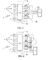
- FIG. 6 relates to an AC distributed PV system with n PV cells, m DC/AC converters 9 having each an associated MPPT control unit 11. The outputs of the DC/AC converters 9 are connected through common output lines to load 7.
- FIG. 8 relates to a system with n PV cells, m DC/DC converters 9 having each an associated MPPT control unit 11.
- the outputs of the DC/DC converters 9 are connected to a reconfiguration module 3.5 as described in WO2010/070621 in the name of the applicant, the output of the reconfiguration module being connected to an output DC/AC convener 37 which is connected to load 7.
- Dynamically reconfigurable serial and/or parallel connections of the converters 9 outputs are considered with the reconfiguration module 35, leading to an increased reliability in case of a DC/DC converter 9 fault.
- increased reliability and longer life time can be achieved through redundancy in the conversion stage.
- the power produced by functional electricity generating cell 3 connected to a defaulting converter 9 is recovered by rerouting the energy flow to the converters 9 that are in a working operation state.
- Figure 9 differs from the embodiment shown in figure 1 by the fact that the energy routing module 13 comprises furthermore at least 2p outputs, p being a positive integer number and p ⁇ 1 (in the present case p-1), connected to correspondent 2p input terminals of the energy routing module 13 forming a loop connection 40 between said 2p outputs and said 2p input terminals.
- the energy routing module 13 comprises furthermore at least 2p outputs, p being a positive integer number and p ⁇ 1 (in the present case p-1), connected to correspondent 2p input terminals of the energy routing module 13 forming a loop connection 40 between said 2p outputs and said 2p input terminals.
- the embodiment of figure 10 differs from the embodiment of figure 1 by the fact that the outputs of static converters 9 are not connected to the load 7 but to correspondent input terminals of the energy routing module 13.
- the energy routing module 13 comprises two loop connections 40, each comprising a static converter 9 with its MPPT control unit 11.
- the present invention allows optimizing power harvesting from electricity generating cells 3 through adaptive and dynamic rerouting of the energy / power at the output of the electricity generating cells 3 while decreasing the cost of the system in reducing the necessary number of converters 9 and increasing the reliability of the electricity generating system 1.
Landscapes
- Engineering & Computer Science (AREA)
- Computer Hardware Design (AREA)
- Microelectronics & Electronic Packaging (AREA)
- Power Engineering (AREA)
- Physics & Mathematics (AREA)
- Condensed Matter Physics & Semiconductors (AREA)
- Electromagnetism (AREA)
- Sustainable Development (AREA)
- Life Sciences & Earth Sciences (AREA)
- General Physics & Mathematics (AREA)
- Sustainable Energy (AREA)
- Charge And Discharge Circuits For Batteries Or The Like (AREA)
- Supply And Distribution Of Alternating Current (AREA)
- Secondary Cells (AREA)
- Photovoltaic Devices (AREA)
- Control Of Electrical Variables (AREA)
Abstract
The invention relates to an electronic management system (5) for electricity generating cells (3), the system comprising:
- cell connection terminals to be connected to n associated electricity generating cells (3), n being a positive integer number,
- outputs to be connected to m associated static converters (9); m being a positive integer number and at least m =2,
- an energy routing module (13) adapted for routing energy flows from and between said cell connection terminals towards said outputs; and
- an electronic control unit (15) adapted for controlling dynamically the energy routine module (13).
Description
- The present invention relates to the field of electricity generating cells such as photovoltaic generators and more specifically to an electronic management system for electricity generating cells, an electricity generating system and a method for electronically managing energy flow.
- Standard photovoltaic installations comprise in general a centralized converter which has typically only one input channel able to perform individual Maximum Power Point Tracking (MPPT).
- Photovoltaic modules are made of several strings of cells (for example 3 strings in a panel). A string of cells is the serial connection of several photovoltaic cells (for example 32 cells per string in one panel). These strings of cells are serial connected in the photovoltaic junction-box.
- To each of these strings a by-pass diode can be associated in the photovoltaic junction box. These by-pass diodes aim to prevent damaging of photovoltaic cells when partial shadowing occurs (hot-spot). The photovoltaic modules are then serial connected to rise-up the voltage and match the nominal voltage of the central converter.
- Several strings of modules can finally be parallel connected to match the nominal power of the central converter.
- In this configuration, shading by chimneys, trees, power lines, soiling from dust, debris, and bird droppings, (and also panels' mismatch due to manufacturing tolerance, ageing, etc.) can cause significant power losses in both shaded and non-shaded modules.
- Even more, it is commonly reported that, on average, residential and
commercial installations arc 25% smaller than they could be, because they are designed around shadowing problems and irregular roof shapes. - A solution to this problem might be to use a distributed photovoltaic system architecture. The concept of a distributed photovoltaic system has become possible with the deployment of micro-converters or micro-inverters able to perform MPPT at a photovoltaic module scale (or even a string of photovoltaic modules scale).
- However, this association of multiple micro-converters, or micro-inverters, can only solve a part of the problems related to partial shadowing and different tilt or orientation angles of photovoltaic modules.
- In addition, the increasing number of micro-converter results in a cost increase of such photovoltaic panels.
-
US 6 350 944 relates to a solar module with reconfigurable tile. - This document describes a reconfigurable solar cell panel having a system of integrated solar-power generation cells with monitoring control and reconfiguration circuitry in a modular array scheme. A plurality of solar cells is packaged on a printed circuit board to form a solar module, also known as a solar module array reconfigurable tile (SMART) module. A solar panel is made up of a plurality of modules that are electrically connected together. The printed circuit board is the physical support structure for the array of solar cells and provides the electrical connection paths between the solar cells comprising the solar cell module. Each solar cell on the module is part of a matrix of solar cells. A plurality of modules is assembled into a solar panel.
- However, the solution in this document is cumbersome and expensive as routing as well as switching takes place between the solar cells on the substrate. In addition, not only routing lines for energy flow, but also control lines for controlling the transistors have to be foreseen which will render solar panels more expensive. This document is silent to connection of the solar panel to a converter.
-
WO2008076301 discloses a photovoltaic module utilizing a flex circuit for reconfiguration. - Even if this document discloses that photovoltaic cells may be connected in series, in parallel or isolated upon the environmental conditions, only one converter is used. Thus reconfiguration and therefore converter capacities are not used in an optimized manner.
- The present invention aims at mitigating, at least partially, the drawbacks described above, in particular for enhancing power conversion.
- For this purpose, the invention proposes an electronic management system for electricity generating cells, the system comprising:
- cell connection terminals to be connected to n associated electricity generating cells, n being a positive integer number,
- outputs to be connected to m associated static converters; m being a positive integer number and at least m -2,
- an energy routing module adapted for routing energy flows from and between said cell connection terminals towards said outputs ; and
- an electronic control unit adapted for controlling dynamically the energy routing module.
- Thanks to the dynamical energy routing to the converters, power conversion can be optimized. The electronic management system is versatile to adapt to many different situations. The electronic management system does not interfere with the construction of the electricity venerating cells and can be integrated in a simple way in an electricity generating system.
- According to other characteristics taken alone or in combination:
- According to one aspect, m being a positive integer less than n.
- This contributes for minimizing the number of used converters and reducing the overall cost of the electricity in particular compared to a fully distributed power conversion system.
- According to another aspect, the system comprises at least 2n cell connection terminals and at least 2m outputs.
- According to one aspect, the energy routing module comprises an electrical connection map between said cell connection terminals and said outputs and switches disposed in the electrical connection map for routing the energy from and between at least one of said cell connection terminals to at least one of said outputs.
- The electrical connection map and the switches may be configured to provide at said outputs several serial and/or parallel connections of said cell connection terminals.
- According to one aspect, the switches have low ohmic resistance in conduction state.
- Said switches may be electromechanical switches, MOSFET transistors or IGBT switches.
- According to another aspect, the electronic control unit comprises at least one sensor and is arranged to reconfigure dynamically the switches of said energy routing module in function of the output of said sensor.
- Said at least one sensor may be at least one of the sensors within the group comprising a voltage and/or current sensor at a cell connection terminal and/or output of said energy routing module.
- The electronic control unit may be arranged to reconfigure dynamically the switches of said energy routing module upon a change in a control parameter, which control parameter may be at least one parameter of the group of parameters comprising: environmental temperature, irradiance of at least one photovoltaic cell, a converter duty cycle of at least one converter, a failure flag, produced power level.
- According to another example, the electronic control unit is arranged to reconfigure dynamically the switches of said energy routing module on a periodically basis.
- According to a further example, the electronic control unit may be arranged to reconfigure dynamically the switches of said energy routing module upon an estimated optimal power output based on past energy routing configurations.
- Furthermore, the electronic control unit may be arranged to reconfigure the switches of said energy routing dynamically module upon the optimisation of a power cost function.
- The electronic control unit may be configured to alternate period of operation of said outputs.
- According to another embodiment the energy routing module comprises furthermore at least p supplementary outputs, p being a positive integer number and p≥1, connected to correspondent p supplementary input terminals of said energy routing module forming a loop connection between said p outputs and said p input terminals.
- At least one of said loop connections may comprise a static converter.
- The invention concerns also an electricity generating system comprising:
- at least n electricity generating cells, n being a positive integer number,
- at least m static converters; m being a positive integer number and at least m =2, and
- an electronic management system as decribed above, the electronic management system comprising:
- cell connection terminals connected to n associated electricity generating cells,
- outputs connected to m associated static converters;
- an energy routing module adapted for routing energy flows from and between said cell connection terminals towards said outputs ; and
- an electronic control unit adapted for controlling dynamically the energy routing module.
- In some embodiments m may be less than n.
- The electricity generating cells may be photovoltaic cells, photovoltaic strings comprising several photovoltaic cells, or electrochemical cells or fuel cells.
- According to one aspect, said converters comprise an MPPT control unit.
- Said m static converters may be divided in at least two groups of converters exhibiting different power ranges and/or conversion technology.
- The invention also concerns a method for electronically managing energy flow between at least n electricity generating cells, n being a positive integer number, and at least m static converters; m being a positive integer number and at least m -2, comprising the step of dynamically routing energy flows from and between cell connection terminals connected to the electricity generating cells towards said outputs.
- According to one aspect, m may be less than n.
- According to one aspect the method comprises the following steps :
- detection of operation state of converters between working converters and non-working converters because of a failure;
- dynamically routing energy flows from and between 2n cell connection terminals connected to the electricity generating cells towards said working converters.
- According to another aspect where said electricity generating cells are photovoltaic cells, the method may comprise the following steps :
- detection of irradiance state of PV cells between at least two classes of irradiance states in particular shaded PV cells and non-shaded PV-cells;
- dynamically routing energy flows from and between cell connection terminals connected to the electricity generating cells towards said converters in connecting only PV cells of same class of irradiance state in series to a converter.
- According to another aspect the period of operation of said outputs is alternated in a rotating manner to equalize the operation time and/or the energy processed by each converter.
- Other advantages and characteristics will appear with the reading of the description of the following figures, among which:
-
FIG. 1 shows an example of an electricity generating system with an electronic management system according to the invention, -
FIG. 2 shows an example of an electronic control unit of the electronic management system ofFIG. 1 , -
FIG. 3 shows an example of an electricity generating system with an electronic management system with three PV cells and two converters, -
FIG. 4A to 4I . show examples of configuration of the electronic management system ofFIG. 3 , -
FIG. 5 shows a possible embodiment of an electronic management system for a DC distributed PV system, -
FIG. 6 shows a possible embodiment of an electronic management system for a AC distributed PV system, -
FIG. 7 shows an embodiment of an electronic management system with a multi-string converter, -
FIG. 8 shows an embodiment of an electricity generating system with an electronic management system according to the invention and a reconfiguration module connected between the converters and an output converter, -
FIG. 9 shows an evolution of an electricity generating system similar to the example offigure 3 , -
FIG. 10 shows another evolution of an electricity generating system similar to the example offigure 3 , and -
FIG. 11 shows another evolution of an electricity generating system similar to the example offigure 6 . - On all the figures the same references refer to the same elements.
-
FIG.1 schematically illustrates anelectricity generating system 1 comprising electricity generating cells 3 (31, 32, 33, ...3n; n being a positive integer). - Such
electricity generating cells 3 may be photovoltaic cells (PV cells), photovoltaic strings comprising several PV cells, electrochemical cells, fuel cells or any part of a modular electricity generator. - The following description focuses more specifically on PV cells and PV strings, but does not exclude other sources of renewable electric energy or electrical storage devices.
- In the case of inorganic materials, a photovoltaic cell essentially consists of a diode (pin or pn junction) made up from a semiconductor material. This material has the property of absorbing light energy, a significant portion of which may be transferred to charge carriers (electrons and holes). With the structure of a diode (pin or pn junction)-with doping of two areas of type N and of type P respectively-optionally separated by a non-doped region (called an "intrinsic" region and designated by "i" in the pin junction)-it is possible to separate the charge carriers in order to then collect them via electrodes which the photovoltaic cell includes. The potential difference (open-circuit voltage, Voc and the maximum current (short-circuit current Isc) which may be provided by the photovoltaic cell depend both on the constitutive materials of the assembly of the cell and on the conditions surrounding this cell (including illumination through spectral intensity, temperature...).
- In the case of organic materials, the models are substantially different-making further reference to the notion of donor and acceptor materials in which electron-hole pairs called excitons are created. The final purpose remains the same: separate the charge carriers for collecting and generating a current.
- As shown on
FIG. 1 , theelectricity generating cells 3 are connected to anelectronic management system 5. Theelectronic management system 5 is connected either directly to aload 7, or indirectly viastatic converters 9. - The
load 7 may be a direct consumer, a storage system, or an electrical grid / network. - In the present example,
static converters 9 are DC-DC converters, but DC/AC converters may also be used instead dependent on theload 7. - Each converter is associated with an
MPPT control unit 11 for tracking the maximum power point (or MPPT i.e. Maximum Power Point Tracker) for collecting the electric energy produced by thePV cells 3 in order to deliver it to theload 7. - Depending on the needs of the
load 7, theconverters 9 may be led to increasing or lowering the output voltage and/or to rippling the output voltage. - The
MPPT control units 11 are designed in order to control theconverters 9 in order to obtain an input voltage which corresponds to an optimum voltage value Vopt i.e. corresponding to a maximum point of the power characteristic. - The maximum power point depends on several variable parameters over time, notably on the sunlight present, on the temperature of the PV cells or on the number of PV cells in an operating state as it will be discussed later on.
- In this way, the yields of the PV cells are not affected too much by the malfunction or the shadowing of certain cells.
- For example, the maximum power point tracker MPPT control may apply an algorithm which identifies the influence of a voltage change on the power delivered at its input by the
PV cells 3 through theelectronic management system 5 and causes a shift in the voltage in the direction identified as increasing the power. - Thus, such an algorithm consists of measuring the power delivered by the
converter 9 for a first voltage and, after a certain time, of imposing a second voltage greater than the first and then measuring or estimating the corresponding power. - In the case when the power corresponding to the second voltage is greater than the power corresponding to the first voltage, the following step of the algorithm is to impose an even greater third voltage. In the opposite case, the third applied voltage is lower than the first voltage. Thus, gradually the system may permanently adapt the voltage to the input terminals of the
converters 9 in order to approach the maximum power point as closely as possible. It is understood that other algorithms may be applied for the MPPT control. - More specifically, the
electronic management system 5 comprises anenergy routing module 13 and anelectronic control unit 15 controlling theenergy routing module 13. - As can be seen on
FIG. 1 , eachPV cell 3 has two terminals connected to two corresponding cell connection terminals of theenergy routing module 13. - In a not represented alternative, it is possible that two PV cells share a common cell connection terminal of the
energy routing module 13. - Thus, in the
present embodiment 2n cell connection terminals of theenergy routing module 13 are connected to n associatedelectricity generating cells 3. - The
energy routing module 13 has outputs to be connected to associatedstatic converters 9 or directly to load 7. In the present case the routing module has 2m outputs m being a positive integer number. - However, it is possible to have for example an impair number of outputs. This can be interesting when using a multi-level converter.
- In the present case m is less than n and at least m =2, which allows a lower number of static converters But in other embodiments, one may consider m equal or higher than n without losing the benefit of the present invention.
- The
energy routing module 13 is adapted for routing energy flows from and between its cell connection terminals towards its outputs. - The
energy routing module 13 is controlled by theelectronic control unit 15 which is adapted for controlling dynamically theenergy routing module 13. - "Dynamically" means that the
control unit 15 will consider from time to time the status of theenergy routing module 13 and may apply control commands that will change of the status of theenergy routing module 13. Thus, the electronic control unit controls as an on-going process, on a continuous basis theenergy routing module 13 for optimizing the energy flow from the electricity generating cells to the static converters. - A specific, but non-limiting example of an
energy routing module 13 is shown infigure 3 which exhibits an example of anelectricity generating system 1 with anelectronic management system 5 with three PV cells 3 (31, 32, 33) and two static converters 9 (91, 92). - In this example, the
energy routing module 13 has six cell connection terminals (Ik, k being a positive integer; l≤k≤6) and four outputs (O1, l being a positive integer; 1≤l≤4). - As can be seen, the
energy routing module 13 comprises anelectrical connection map 17 between said cell connection terminals and said outputs allowing that each cell connection terminal Ik may be connected through electrical connections to each output O1, but also that a cell connection terminal Ik may be connected to another cell connection terminal Ij, j being an integer j≠k. - Therefore a cell connection terminal of the
energy rousing module 13 may be considered as an input if energy / current is flowing from aPV cell 3 into the energy routing module and may be considered as an output if energy / current is flowing from the energy routing module to aPV cell 3. The latter will be the case when for example two PV cells are put in series connection. - It can be understood that in other examples less combinations may be envisaged, leading therefore to the fact that a cell connection terminal may not be connected to all other cell connection terminals or outputs of the
energy routing module 13. - Furthermore, the energy routing module comprises switches S (fifteen switches (Sp, p being an positive integer; 1≤p≤15) disposed in the
electrical connection map 17 for routing the energy from or between at least one of said cell connection terminals Ik to at least one of said outputs O1. - For example if switch S15 is closed, input I1 is connected to output O1.
- However, when switch S15 is closed, S13 and S14 open, S8 closed, S7 and S0 open and S3 closed,
PV cell static converter 91. - Therefore the
electrical connection map 17 and said switches S are configured to provide at said outputs several serial and/or parallel connections of said cell connection terminals of theenergy routing module 13. - The switches S have low ohmic resistance in conduction state, for example less than 10 mΩ.
- The switches S may be electromechanical switches, MOSFET transistors or IGBT switches.
- Turning now to
FIG. 2 showing more in detail an example of anelectronic control unit 15. - The
electronic control unit 15 comprises at least onesensor 21 and is arranged to configure or reconfigure dynamically the switches S of saidenergy routing module 13 in particular in function of the output and measurements of saidsensor 21. Configuration or reconfiguration of a switch S means to control the switching state or position (passing state / blocking state) of a switch S of saidenergy routing module 13. - The
sensor 21 may be a voltage and/or current sensor at a cell connection terminal and/or output of saidenergy routing module 13. - Worthless to say that there may be
several sensors 21 measuring different parameters as mentioned as example here above. - The
electronic control unit 15 furthermore comprises aprocessing unit 23 such as a microprocessor comprising a memory and a software program installed thereon, and a drivingunit 25 for driving said switches S upon instructions received from the microprocessor. - The
electronic control unit 15 is arranged to reconfigure dynamically the position of the switches S of saidenergy routing module 13 upon a change in a control parameter. This is typically implemented through the software and an adapted optimisation algorithm. - The parameter that may trigger the reconfiguration of the switch positions may be, among other examples, the environmental temperature, irradiance of at least one photovoltaic cell, a converter duty cycle of at least one converter, any failure flag, the overall level of produced power. This allows taking into account for example shadowing effect on at least one
cell 3. - According to an alternative, the
etectronic control unit 15 with itsprocessing unit 23 is arranged to reconfigure dynamically the switches S of said energy routing module on a periodically basis, for example every 5 minutes. - This aims to regular update the switching configuration in order to optimize power output.
- According to another alternative the
electronic control unit 15 is arranged to reconfigure the switches of saidenergy routing module 13 upon an estimated optimal power output based on past energy routing configurations. In this case, theelectronic control unit 15 safeguards past switching configurations related to, for example, measured values of at least onesensor 21 and / or environmental conditions and/ or delivered output power in an internal memory or database or evolving model in order to forecast optimum switching configurations for future situations. - According to another alternative, a power cost function software is implemented in the
processing unit 23 and theelectronic control unit 15 is arranged to reconfigure the switches of said energy routing module upon such a power cost function routine. - According to another alternative, the
electronic Control unit 15 is configured to alternate period of operation of said outputs and therefore the operation time of thestatic converters 9, for example in a rotating process. This aims to smooth and equalize the operation time of thestatic converters 9, in particular to increase lifetime of such converters. - It is therefore easily understandable that the present solution allows reconfiguring dynamically the switching between the electricity generating cells, allowing therefore adapting at best to the current and/or voltage at the output of the
energy routing module 13 to the inputs of theconverters 9, allowing thus to achieve best operation conditions for theconverters 9. - Such dynamic reconfiguration is achieved by implementing for example in software a method for electronically managing energy flow between at least n
electricity generating cells 3, and at least mstatic converters 9, at least m =2, comprising the step of dynamically routing energy flows from and between cell connection terminals connected to the electricity generating cells towards said outputs. - Therefore, in an
electricity generating system 1, the number of converters can be reduced and optimized in order to allow responding to shadowing effects while avoiding associating one converter to oneelectricity generating cell 3 like in fully distributed architectures. - Thanks to the above described
electronic management system 5, it is even possible and envisaged that the mstatic converters 9 are divided in at least two groups ofconverters 9 exhibiting for example different power ranges (using or not the same power conversion technology). Thus the converters of one group are different from the converters of the other groups and therefore dedicated to specific / specialized uses. - This means that for example in
FIG. 3 that one of theconverters 9 may have for example half of the nominal power of theother converter 9 allowing also some supplemental cost reduction and increase in performance. - Another example could be in pooling several specialized converters. For instance with a pool of DC/DC converters, some can be buck only (specifically reducing the voltage), others can be boost only (specifically increasing the voltage), and other can be buck/boost (able to increase or decrease the voltage), leading again to some supplemental cosl reduction and increase in performance.
- Furthermore, the above described
electronic management system 5 renders anelectricity generating system 1 more robust because in case of failure of one of theconverters 9, the rerouting of the energy from thecells 3 to the workingconverters 9 can maintain power output, even without, any loss. - Indeed, the optimisation algorithm implemented in the
processing unit 23 may comprise a method where the operation state of theconverters 9 is detected between working converters and non-working converters because of a failure or dysfunction, and in response to such failure detection. - Then, the optimization algorithm dynamically drives the switches S of the
energy routing modules 13 for routing energy flows from and between 2n cell connection terminals connected to theelectricity generating cells 3 towards theconverters 9 that are in a working operation state. Thus no power generated by thecells 3 may be lost. -
FIG. 4A - 4I . show examples of possible switching configurations of theenergy routing module 13 allowing better understanding of the present invention. In these figures, a cloud on onePV cell 3 means that such a cell is affected by a shadowing effect. - In
FIG. 4A and 4B , allPV cells 3 arc connected in series, but only onestatic converter 9 is used in either of both configurations. - In
FIG. 4C , allPV cells 3 arc connected in series and bothconverter 9 are used in parallel. - In
FIG. 4D, 4E and 4F , a shadow affects one (33 inFIG. 4D ;3 2 inFIG. 4E ;3 1 inFIG. 4F ) of the threePV cells 3. ThePV cell 3 affected by the shadow is isolated and connected to oneconverter 9 whereas the othernon-affected PV cells 3 are connected in series to theother converter 9, assuring therefore optimal power harvesting. - In
FIG. 4G, 4H and 4I , a shadow affects two of the threePV cells 3. ThePV cell 3 not affected by the shadow is isolated and connected to oneconverter 9 whereas the other affectedPV cells 3 arc connected in series to theother converter 9. Such a configuration is either more efficient in this situation of irradiance. - More generally speaking the optimisation algorithm implemented in the
processing unit 23 may comprise a method where the irradiation state of thePV cells 3, is detected, in particular between shaded and non-shaded cells or other classes of irradiance states. - Then, the optimization algorithm dynamically drives the switches S of the
energy routing modules 13 for routing energy flows from and between 2n cell connection terminals connected to theelectricity generating cells 3 towards theconverters 9 in connectingonly PC cells 3 of same irradiance state or belonging to the same class of irradiance state in series to aconverter 9. - In
FIG. 4J, 4K and 4L , a shadow affects all of the threePV cells 3. - In
FIG. 4J and 4K , allPV cells 3 are connected in series, but only oneStatic converter 9 is used in either of both configurations. - In
FIG. 4L , allPV cells 3 are connected in series and bothconverter 9 arc used in parallel. - During functioning, the
control unit 15 drives for example in the morning, when sun power is not yet at maximum on a periodically basis (for example every 5 minutes) between configurations shown inFIG. 4A and 4B . When the sun rises, thecontrol unit 15 detects rising up of irradiance by asensor 21, and drives theenergy routing module 15 to the configuration shown inFIG. 4C . - Let's assume that a cloud will successively shadow one of the
PV cells control unit 15 and itssensors 21. In this case, thecontrol unit 15 drives theenergy routing module 13 successively to the configurations shown inFIG. 4F, 4E, 4D .... etc. - One understand thus easily the benefit of the
energy management system 5 which allows to supply an optimal voltage / currents range to the inputs of theconverters 9 in function of the real power generating conditions of theelectricity generating cells 3. -
FIG. 5-10 show specific examples ofelectricity generating system 1. -
FIG. 5 relates to a DC distributed PV system with n PV cells, m DC/DC converters 9 having each an associatedMPPT control unit 11. The outputs of the DC/DC converters 9 are connected to acombine box 30 which output is connected to a DC/AC converter 32. Fixed serial or parallel connections of theconverters 9 can be considered in thecombiner box 30. The outputs of the DC/AC converter 32 are connected to load 7. -
FIG. 6 relates to an AC distributed PV system with n PV cells, m DC/AC converters 9 having each an associatedMPPT control unit 11. The outputs of the DC/AC converters 9 are connected through common output lines to load 7. -
FIG. 7 relates to a PV system with n PV cells where the m outputs of theenergy routing module 13 are connected to the correspondent inputs of a DC/AC multistring converter 9 which outputs are connected to load 7. -
FIG. 8 relates to a system with n PV cells, m DC/DC converters 9 having each an associatedMPPT control unit 11. The outputs of the DC/DC converters 9 are connected to a reconfiguration module 3.5 as described inWO2010/070621 in the name of the applicant, the output of the reconfiguration module being connected to an output DC/AC convener 37 which is connected to load 7. - Dynamically reconfigurable serial and/or parallel connections of the
converters 9 outputs are considered with thereconfiguration module 35, leading to an increased reliability in case of a DC/DC converter 9 fault. For instance, considering maintenance free system applications (embedded system, remote or inaccessible system...), increased reliability and longer life time can be achieved through redundancy in the conversion stage. One may therefore take advantage of the use of the present invention introducing theelectronic routing module 13 between theelectricity generating cells 3 and thestatic converters 9 connected to the output DC/AC converter through areconfiguration module 35, for example in reducing the base number of converters or micro-converters achieving the same level of reliability using less converters. Furthermore in this case, and as stated here above, the power produced by functionalelectricity generating cell 3 connected to a defaultingconverter 9 is recovered by rerouting the energy flow to theconverters 9 that are in a working operation state. -
Figure 9 differs from the embodiment shown infigure 1 by the fact that theenergy routing module 13 comprises furthermore at least 2p outputs, p being a positive integer number and p≥1 (in the present case p-1), connected to correspondent 2p input terminals of theenergy routing module 13 forming aloop connection 40 between said 2p outputs and said 2p input terminals. - This allows increasing the possibilities of combinations of
electricity generating cells 3. In particular, this allows to group groups ofelectricity generating cells 3. - The embodiment of
figure 10 differs from the embodiment offigure 1 by the fact that the outputs ofstatic converters 9 are not connected to theload 7 but to correspondent input terminals of theenergy routing module 13. In other words, with regards to the embodiment offigure 10 , theenergy routing module 13 comprises twoloop connections 40, each comprising astatic converter 9 with itsMPPT control unit 11. - Thanks to this configuration, the same functioning as described with regard to the embodiment of
figure 8 may be achieved. In addition, dynamical master-slave configurations can be realized for optimized power conversion. - The embodiment of
figure 11 differs from the embodiment offigure 6 by the fact that one 99 ofstatic converters 9 is a multi-level converter. Therefore, forconverter 99, three outputs of theenergy routing module 13 are connected to respective entries of themulti-level converter 99. - An example of a multilevel converter is disclosed in ScienceDirect Solar Energy 84 (2010) 1175-1186 "Direct power control of gird connected PV systems with Three level NPC inverter" in particular with respect to figure 3 (b). Such configuration may be advantageous for direct connection to a grid.
- The present invention allows optimizing power harvesting from
electricity generating cells 3 through adaptive and dynamic rerouting of the energy / power at the output of theelectricity generating cells 3 while decreasing the cost of the system in reducing the necessary number ofconverters 9 and increasing the reliability of theelectricity generating system 1.
Claims (22)
- An electronic management system (5) for electricity generating cells (3), the system comprising:- cell connection terminals to be connected to n associated electricity generating cells (3), n being a positive integer number,- outputs to be connected to m associated static converters (9); m being a positive integer number at least m =2,- an energy routing module (13) adapted for routing energy flows from and between said cell connection terminals towards said outputs ; and- an electronic control unit (15) adapted for controlling dynamically the energy routing module (13).
- System according to claim 1, where m is a positive integer number less than n.
- System according to claim 2, where the system comprises at least 2n cell connection terminals and at least 2m outputs.
- System according to any of claims 1 to 3, where the energy routing module (13) comprises an electrical connection map (17) between said cell connection terminals and said outputs and switches (S) disposed in the electrical connection map for routing the energy from and between at least one of said cell connection terminals to at least one of said outputs.
- System according to claim 4, where said electrical connection map (17) and said switches (S) are configured to provide at said outputs several serial and/or parallel connections of said cell connection terminals.
- System according to any of claims 1 to 5, where said electronic control unit (15) comprises at least one sensor (21) and is arranged to reconfigure dynamically the switches (S) of said energy routing module (13) in function of the output of said sensor (21).
- System according to claim 6, where said at least one sensor (21) is at least one of the sensors within the group comprising a voltage and/or current sensor at a cell connection terminal and/or output of said energy routing module.
- System according to any of claims 1 to 7, where said electronic control unit (15) is arranged to reconfigure dynamically the switches (S) of said energy routing module (15) upon a change in a control parameter.
- System according to any of claims 1 to 5, where said electronic control unit (15) is arranged to reconfigure dynamically the switches (S) of said energy routing module (13) on a periodically basis.
- System according to any of claims 1 to 5, where said electronic control unit (15) is arranged to reconfigure dynamically the switches (S) of said energy routing module (13) upon an estimated optimal power output based on past energy routing configurations.
- System according to any of claims 1 to 5, where said electronic control unit (15) is arranged to reconfigure dynamically the switches (S) of said energy routing module (13) upon the optimisation of a power cost function.
- System according to any of claims 1 to 5, where the electronic control unit (15) is configured to alternate period of operation of said outputs.
- System according to any of claims 1 to 12, where said energy routing module (13) comprises furthermore at least p supplementary outputs, p being a positive integer number and p≥1, connected to correspondent p supplementary input terminals of said energy routing module (13) forming a loop connection (40) between said p supplementary outputs and said p supplementary input terminals.
- System according to claim 13, where at least one of said loop connections (40) comprises a static converter (9).
- Electricity generating system (1) comprising:- at least n electricity generating cells (3), n being a positive integer number,- at least m static converters (9); m being a positive integer number and at least m =2, and- an electronic management system (5) according to any preceding claim, the electronic management system (5) comprising:- cell connection terminals connected to n associated electricity generating cells (3),- outputs connected to m associated static converters (9);- an energy routing module (13) adapted for routing energy flows from and between said cell connection terminals towards said outputs ; and- an electronic control (15) unit adapted for controlling dynamically the energy routing module.
- System according to claim 15, where m is a positive integer number less than n.
- System according to claim 15, where said m static converters (9) are divided in at least two groups of converters exhibiting different power ranges and/or conversion technology.
- Method for electronically managing energy flow between at least n electricity generating cells (3), n being a positive integer number, and at least m static converters (9); m being a positive integer number and at least m =2, comprising the step of dynamically routing energy flows from and between cell connection terminals connected to the electricity generating cells (3) towards said outputs, at least some outputs being connected to said at least m static converters.
- Method according to claim 15, where m is less than n.
- Method according to claim 18 or 19, comprising the following steps- detection of operation state of converters (9) between working converters and non-working converters (9) because of a failure:- dynamically routing energy flows from and between cell connection terminals connected to the electricity generating cells (3) towards said working converters (9).
- Method according to any of claims 18 to 20, where said electricity generating cells (3) are photovoltaic cells comprising the following steps:- detection of irradiance state of PV cells (3) between at least two classes of irradiance states in particular shaded PV cells (3) and non-shaded PV-cells (3);- dynamically routing energy flows from and between cell connection terminals connected to the electricity generating cells (3) towards said converters (9) in connecting only PV cells (3) of same class of irradiance state in series to a converter (9).
- Method according to claim any of claims 18 to 19 where the period of operation of said outputs is alternated in a rotating manner to equalize the operation time and/or the energy processed by each converter (9).
Priority Applications (10)
| Application Number | Priority Date | Filing Date | Title |
|---|---|---|---|
| EP13290035.8A EP2770539A1 (en) | 2013-02-20 | 2013-02-20 | Electronic management system for electricity generating cells, electricity generating system and method for electronically managing energy flow |
| JP2015558445A JP6356703B2 (en) | 2013-02-20 | 2014-02-20 | Electronic management system for power generation cell, power generation system, and method for electronically managing energy flow |
| MX2015010592A MX352335B (en) | 2013-02-20 | 2014-02-20 | Electronic management system for electricity generating cells, electricity generating system and method for electronically managing energy flow. |
| PCT/EP2014/053299 WO2014128202A1 (en) | 2013-02-20 | 2014-02-20 | Electronic management system for electricity generating cells, electricity generating system and method for electronically managing energy flow |
| US14/769,349 US9627893B2 (en) | 2013-02-20 | 2014-02-20 | Electronic management system for electricity generating cells, electricity generating system and method for electronically managing energy flow |
| KR1020157022339A KR20150120984A (en) | 2013-02-20 | 2014-02-20 | Electronic management system for electricity generating cells, electricity generating system and method for electronically managing energy flow |
| EP14711166.0A EP2959515A1 (en) | 2013-02-20 | 2014-02-20 | Electronic management system for electricity generating cells, electricity generating system and method for electronically managing energy flow |
| AU2014220730A AU2014220730B2 (en) | 2013-02-20 | 2014-02-20 | Electronic management system for electricity generating cells, electricity generating system and method for electronically managing energy flow |
| CN201480016329.5A CN105264671B (en) | 2013-02-20 | 2014-02-20 | Method for the electronic management system of generating battery, electricity generation system and for electronically management energy stream |
| ZA2015/05508A ZA201505508B (en) | 2013-02-20 | 2015-07-31 | Electronic management system for electricity generating cells, electricity generating system and method for electronically managing energy flow |
Applications Claiming Priority (1)
| Application Number | Priority Date | Filing Date | Title |
|---|---|---|---|
| EP13290035.8A EP2770539A1 (en) | 2013-02-20 | 2013-02-20 | Electronic management system for electricity generating cells, electricity generating system and method for electronically managing energy flow |
Publications (1)
| Publication Number | Publication Date |
|---|---|
| EP2770539A1 true EP2770539A1 (en) | 2014-08-27 |
Family
ID=47877951
Family Applications (2)
| Application Number | Title | Priority Date | Filing Date |
|---|---|---|---|
| EP13290035.8A Withdrawn EP2770539A1 (en) | 2013-02-20 | 2013-02-20 | Electronic management system for electricity generating cells, electricity generating system and method for electronically managing energy flow |
| EP14711166.0A Withdrawn EP2959515A1 (en) | 2013-02-20 | 2014-02-20 | Electronic management system for electricity generating cells, electricity generating system and method for electronically managing energy flow |
Family Applications After (1)
| Application Number | Title | Priority Date | Filing Date |
|---|---|---|---|
| EP14711166.0A Withdrawn EP2959515A1 (en) | 2013-02-20 | 2014-02-20 | Electronic management system for electricity generating cells, electricity generating system and method for electronically managing energy flow |
Country Status (9)
| Country | Link |
|---|---|
| US (1) | US9627893B2 (en) |
| EP (2) | EP2770539A1 (en) |
| JP (1) | JP6356703B2 (en) |
| KR (1) | KR20150120984A (en) |
| CN (1) | CN105264671B (en) |
| AU (1) | AU2014220730B2 (en) |
| MX (1) | MX352335B (en) |
| WO (1) | WO2014128202A1 (en) |
| ZA (1) | ZA201505508B (en) |
Cited By (3)
| Publication number | Priority date | Publication date | Assignee | Title |
|---|---|---|---|---|
| WO2018002586A1 (en) * | 2016-06-29 | 2018-01-04 | Xiongwei Liu | Electrical coupling apparatus for use in a solar photovoltaic power system and methods of operating the same |
| CN107910573A (en) * | 2017-11-08 | 2018-04-13 | 南京晓庄学院 | A kind of reversible fuel cell heap energy saver and control method |
| EP4032180A4 (en) * | 2019-09-16 | 2023-06-21 | WH Mechanical Engineering Inc. | An apparatus, method and article for maximizing solar charge current through the use of split wire(s) in a solar array with solar panels connected in the combination of series and parallel |
Families Citing this family (13)
| Publication number | Priority date | Publication date | Assignee | Title |
|---|---|---|---|---|
| US9985572B2 (en) * | 2015-04-30 | 2018-05-29 | Glenn Arthur Hastings | Solar roadway system and method |
| JP2017059094A (en) * | 2015-09-18 | 2017-03-23 | トヨタ自動車株式会社 | Power generation operation point control circuit device with step-up function of solar battery |
| US10651735B2 (en) | 2017-02-06 | 2020-05-12 | Futurewei Technologies, Inc. | Series stacked DC-DC converter with serially connected DC power sources and capacitors |
| US10665743B2 (en) * | 2017-02-16 | 2020-05-26 | Futurewei Technologies, Inc. | Distributed/central optimizer architecture |
| CN106712698A (en) * | 2017-03-01 | 2017-05-24 | 北京天恒长鹰科技股份有限公司 | Multi-stage hybrid solar cell array and combined power supply method thereof |
| US10333314B2 (en) | 2017-04-17 | 2019-06-25 | Futurewei Technologies, Inc. | Multiple buck stage single boost stage optimizer |
| US20180331543A1 (en) * | 2017-05-15 | 2018-11-15 | Dynapower Company Llc | Energy storage system for photovoltaic energy and method of storing photovoltaic energy |
| EP3410552B1 (en) * | 2017-05-30 | 2022-08-31 | Solaredge Technologies Ltd. | Routing power in a power system |
| WO2019187524A1 (en) * | 2018-03-29 | 2019-10-03 | 住友電気工業株式会社 | Generator unit relocation calculation device and calculation processing method |
| DE102018127130A1 (en) * | 2018-10-30 | 2020-04-30 | Sma Solar Technology Ag | Inverter with at least two DC / DC converters |
| DE102018127132A1 (en) * | 2018-10-30 | 2020-04-30 | Sma Solar Technology Ag | Inverter with at least two DC / DC converters and use of such an inverter in a photovoltaic system |
| JP7249893B2 (en) * | 2019-07-01 | 2023-03-31 | 大和ハウス工業株式会社 | power supply system |
| CN112054503B (en) * | 2020-09-27 | 2022-01-04 | 武汉大学 | Power balancing method based on serial photovoltaic module annular power balancing system |
Citations (9)
| Publication number | Priority date | Publication date | Assignee | Title |
|---|---|---|---|---|
| US6350944B1 (en) | 2000-05-30 | 2002-02-26 | Hughes Electronics Corporation | Solar module array with reconfigurable tile |
| WO2008076301A1 (en) | 2006-12-15 | 2008-06-26 | Miasole | Photovoltaic module utilizing a flex circuit for reconfiguration |
| WO2009060273A1 (en) * | 2007-11-08 | 2009-05-14 | Harald Hauf | Method of operation and device for controlling an energy installation with photovoltaic modules |
| US20100109442A1 (en) * | 2008-10-30 | 2010-05-06 | Asea Brown Boveri, S.A. | System and Method for Energy Optimization in Photovoltaic Generators |
| WO2010070621A1 (en) | 2008-12-18 | 2010-06-24 | Centre National De La Recherche Scientifique | Electronic management system for photovoltaic cells |
| EP2337184A2 (en) * | 2009-12-15 | 2011-06-22 | Samsung SDI Co., Ltd. | Grid-connected energy storage system and method of controlling grid-connected energy storage system |
| EP2372487A2 (en) * | 2010-04-01 | 2011-10-05 | Huawei Technologies Co., Ltd. | Solar light power generation system, control device, and control method thereof |
| FR2961035A1 (en) * | 2010-06-04 | 2011-12-09 | Aeg Power Solutions Bv | MATRIX CONNECTION DEVICE FOR PHOTOVOLTAIC PANELS AND / OR WIND TURBINES |
| EP2518855A2 (en) * | 2011-04-29 | 2012-10-31 | General Electric Company | Switching coordination of distributed DC-DC converters for highly efficient photovoltaic power plants |
Family Cites Families (16)
| Publication number | Priority date | Publication date | Assignee | Title |
|---|---|---|---|---|
| DE59502398D1 (en) * | 1994-09-21 | 1998-07-09 | Inventio Ag | Method and device for variable allocation of inverters in operation to at least one load |
| JPH1069321A (en) * | 1996-08-27 | 1998-03-10 | Honda Motor Co Ltd | Photovoltaic power device |
| JP2001268800A (en) * | 2000-03-16 | 2001-09-28 | Kawasaki Steel Corp | Solar light power generation control method and apparatus |
| JP3656531B2 (en) * | 2000-08-31 | 2005-06-08 | 松下電工株式会社 | Solar power system |
| WO2010056764A2 (en) * | 2008-11-12 | 2010-05-20 | Mehrdad Nikoonahad | High efficiency solar panel and system |
| EP2387820B1 (en) * | 2008-12-18 | 2012-10-24 | ABB Research Ltd. | Converter device and method for controlling a converter device |
| JP5302096B2 (en) * | 2009-05-15 | 2013-10-02 | 株式会社Nttファシリティーズ | Photovoltaic power generation system and control method |
| FR2953997B1 (en) * | 2009-12-11 | 2012-01-20 | Centre Nat Rech Scient | SYSTEM FOR ELECTRONIC MANAGEMENT OF PHOTOVOLTAIC CELLS WITH ADJUSTABLE THRESHOLDS |
| US9036384B2 (en) | 2009-12-24 | 2015-05-19 | Panasonic Intellectual Property Management Co., Ltd. | Power converter having semiconductor switching element |
| DE102010017746A1 (en) * | 2010-05-03 | 2011-11-03 | Sma Solar Technology Ag | Method for limiting the generator voltage of a photovoltaic system in case of danger and photovoltaic system |
| US8853886B2 (en) * | 2010-06-09 | 2014-10-07 | Tigo Energy, Inc. | System for use of static inverters in variable energy generation environments |
| US9299861B2 (en) * | 2010-06-15 | 2016-03-29 | Tenksolar, Inc. | Cell-to-grid redundandt photovoltaic system |
| JP2012090516A (en) * | 2010-10-15 | 2012-05-10 | Sanyo Electric Co Ltd | Switching circuit, control device and power generation system |
| JP2012208725A (en) * | 2011-03-30 | 2012-10-25 | National Institute Of Advanced Industrial & Technology | Photovoltaic power generation system |
| JP5748213B2 (en) * | 2011-06-22 | 2015-07-15 | コア・テック株式会社 | Solar power system |
| US9379543B2 (en) * | 2012-04-10 | 2016-06-28 | Sol Chip Ltd. | Integrated circuit energy harvester |
-
2013
- 2013-02-20 EP EP13290035.8A patent/EP2770539A1/en not_active Withdrawn
-
2014
- 2014-02-20 US US14/769,349 patent/US9627893B2/en active Active
- 2014-02-20 KR KR1020157022339A patent/KR20150120984A/en not_active Application Discontinuation
- 2014-02-20 CN CN201480016329.5A patent/CN105264671B/en not_active Expired - Fee Related
- 2014-02-20 JP JP2015558445A patent/JP6356703B2/en not_active Expired - Fee Related
- 2014-02-20 WO PCT/EP2014/053299 patent/WO2014128202A1/en active Application Filing
- 2014-02-20 MX MX2015010592A patent/MX352335B/en active IP Right Grant
- 2014-02-20 EP EP14711166.0A patent/EP2959515A1/en not_active Withdrawn
- 2014-02-20 AU AU2014220730A patent/AU2014220730B2/en not_active Ceased
-
2015
- 2015-07-31 ZA ZA2015/05508A patent/ZA201505508B/en unknown
Patent Citations (9)
| Publication number | Priority date | Publication date | Assignee | Title |
|---|---|---|---|---|
| US6350944B1 (en) | 2000-05-30 | 2002-02-26 | Hughes Electronics Corporation | Solar module array with reconfigurable tile |
| WO2008076301A1 (en) | 2006-12-15 | 2008-06-26 | Miasole | Photovoltaic module utilizing a flex circuit for reconfiguration |
| WO2009060273A1 (en) * | 2007-11-08 | 2009-05-14 | Harald Hauf | Method of operation and device for controlling an energy installation with photovoltaic modules |
| US20100109442A1 (en) * | 2008-10-30 | 2010-05-06 | Asea Brown Boveri, S.A. | System and Method for Energy Optimization in Photovoltaic Generators |
| WO2010070621A1 (en) | 2008-12-18 | 2010-06-24 | Centre National De La Recherche Scientifique | Electronic management system for photovoltaic cells |
| EP2337184A2 (en) * | 2009-12-15 | 2011-06-22 | Samsung SDI Co., Ltd. | Grid-connected energy storage system and method of controlling grid-connected energy storage system |
| EP2372487A2 (en) * | 2010-04-01 | 2011-10-05 | Huawei Technologies Co., Ltd. | Solar light power generation system, control device, and control method thereof |
| FR2961035A1 (en) * | 2010-06-04 | 2011-12-09 | Aeg Power Solutions Bv | MATRIX CONNECTION DEVICE FOR PHOTOVOLTAIC PANELS AND / OR WIND TURBINES |
| EP2518855A2 (en) * | 2011-04-29 | 2012-10-31 | General Electric Company | Switching coordination of distributed DC-DC converters for highly efficient photovoltaic power plants |
Non-Patent Citations (2)
| Title |
|---|
| SCIENCEDIRECT SOLAR ENERGY, vol. 84, 2010, pages 1175 - 1186 |
| VELASCO-QUESADA G ET AL: "Electrical PV Array Reconfiguration Strategy for Energy Extraction Improvement in Grid-Connected PV Systems", IEEE TRANSACTIONS ON INDUSTRIAL ELECTRONICS, IEEE SERVICE CENTER, PISCATAWAY, NJ, USA, vol. 56, no. 11, 1 November 2009 (2009-11-01), pages 4319 - 4331, XP011270847, ISSN: 0278-0046, DOI: 10.1109/TIE.2009.2024664 * |
Cited By (5)
| Publication number | Priority date | Publication date | Assignee | Title |
|---|---|---|---|---|
| WO2018002586A1 (en) * | 2016-06-29 | 2018-01-04 | Xiongwei Liu | Electrical coupling apparatus for use in a solar photovoltaic power system and methods of operating the same |
| US11018622B2 (en) | 2016-06-29 | 2021-05-25 | Entrust Smart Home Microgrid Ltd. | Electrical coupling apparatus for use in a solar photovoltaic power system and methods of operating the same |
| CN107910573A (en) * | 2017-11-08 | 2018-04-13 | 南京晓庄学院 | A kind of reversible fuel cell heap energy saver and control method |
| CN107910573B (en) * | 2017-11-08 | 2020-10-09 | 南京晓庄学院 | Energy-saving device of reversible fuel cell stack and control method |
| EP4032180A4 (en) * | 2019-09-16 | 2023-06-21 | WH Mechanical Engineering Inc. | An apparatus, method and article for maximizing solar charge current through the use of split wire(s) in a solar array with solar panels connected in the combination of series and parallel |
Also Published As
| Publication number | Publication date |
|---|---|
| US9627893B2 (en) | 2017-04-18 |
| US20160006250A1 (en) | 2016-01-07 |
| EP2959515A1 (en) | 2015-12-30 |
| MX2015010592A (en) | 2016-07-18 |
| JP6356703B2 (en) | 2018-07-11 |
| ZA201505508B (en) | 2021-05-26 |
| JP2016516382A (en) | 2016-06-02 |
| KR20150120984A (en) | 2015-10-28 |
| CN105264671B (en) | 2017-10-24 |
| AU2014220730B2 (en) | 2017-08-31 |
| WO2014128202A1 (en) | 2014-08-28 |
| CN105264671A (en) | 2016-01-20 |
| MX352335B (en) | 2017-11-21 |
| AU2014220730A1 (en) | 2015-08-20 |
Similar Documents
| Publication | Publication Date | Title |
|---|---|---|
| US9627893B2 (en) | Electronic management system for electricity generating cells, electricity generating system and method for electronically managing energy flow | |
| KR101708388B1 (en) | Electronic management system for photovoltaic cells | |
| KR101520981B1 (en) | Localized Power Point Optimizer for Solar Cell Installations | |
| US20110031816A1 (en) | Photovoltaic unit, a dc-dc converter therefor, and a method of operating the same | |
| US10651787B2 (en) | Reconfigurable photovoltaic module | |
| US8664797B2 (en) | Photovoltaic assembly and method of operating a photovoltaic assembly | |
| JP6236582B2 (en) | Electronic management system for solar cells with matching thresholds. | |
| KR101838760B1 (en) | System for the electronic management of photovoltaic cells as a function of meteorology | |
| KR101445711B1 (en) | Solar power system. | |
| JP6155288B2 (en) | Renewable energy unit with simplified connection | |
| KR101638753B1 (en) | Photovoltaic power generation system free of bypass diodes | |
| KR20200113877A (en) | Photovoltaics System having direct current summing control in response to the variation in the output power of the solar panel | |
| US20230327452A1 (en) | Switching matrix for reconfigurable pv modules and systems | |
| Di Dio et al. | A new control system prototype for the energy production maximization of a unequally irradiated PV system | |
| ES2727790A1 (en) | Hybrid converter and its control method (Machine-translation by Google Translate, not legally binding) | |
| Elanchezhian et al. | Design of two-stage soft-switched module Inverter for Photovoltaic applications | |
| Al-rawashdeh et al. | Evaluation of energy harvest increase by distributed maximum power point tracking | |
| KR20170029199A (en) | Photovoltaic Power Generation Apparatus | |
| JP5912417B2 (en) | Solar power plant | |
| KR20200113878A (en) | Photovoltaics System having direct current summing control in response to the variation in the output power of the solar panel using booster | |
| KR20200122557A (en) | Solar photovoltaic generating system using variable array | |
| Liu et al. | Self-reconfiguration strategy for energy extraction improvement of island renewable energy sources | |
| Kadali et al. | A Distributed Maximum Power Point Control For Efficiency Enhancement Of Photovoltaic System |
Legal Events
| Date | Code | Title | Description |
|---|---|---|---|
| PUAI | Public reference made under article 153(3) epc to a published international application that has entered the european phase |
Free format text: ORIGINAL CODE: 0009012 |
|
| 17P | Request for examination filed |
Effective date: 20130220 |
|
| AK | Designated contracting states |
Kind code of ref document: A1 Designated state(s): AL AT BE BG CH CY CZ DE DK EE ES FI FR GB GR HR HU IE IS IT LI LT LU LV MC MK MT NL NO PL PT RO RS SE SI SK SM TR |
|
| AX | Request for extension of the european patent |
Extension state: BA ME |
|
| STAA | Information on the status of an ep patent application or granted ep patent |
Free format text: STATUS: THE APPLICATION IS DEEMED TO BE WITHDRAWN |
|
| 18D | Application deemed to be withdrawn |
Effective date: 20150228 |