EP2756992A1 - Motor vehicle safety arrangement and method - Google Patents
Motor vehicle safety arrangement and method Download PDFInfo
- Publication number
- EP2756992A1 EP2756992A1 EP13151989.4A EP13151989A EP2756992A1 EP 2756992 A1 EP2756992 A1 EP 2756992A1 EP 13151989 A EP13151989 A EP 13151989A EP 2756992 A1 EP2756992 A1 EP 2756992A1
- Authority
- EP
- European Patent Office
- Prior art keywords
- vehicle
- safety belt
- control unit
- sensor
- collision
- Prior art date
- Legal status (The legal status is an assumption and is not a legal conclusion. Google has not performed a legal analysis and makes no representation as to the accuracy of the status listed.)
- Ceased
Links
Images

Classifications
-
- B—PERFORMING OPERATIONS; TRANSPORTING
- B60—VEHICLES IN GENERAL
- B60R—VEHICLES, VEHICLE FITTINGS, OR VEHICLE PARTS, NOT OTHERWISE PROVIDED FOR
- B60R22/00—Safety belts or body harnesses in vehicles
- B60R22/48—Control systems, alarms, or interlock systems, for the correct application of the belt or harness
-
- B—PERFORMING OPERATIONS; TRANSPORTING
- B60—VEHICLES IN GENERAL
- B60R—VEHICLES, VEHICLE FITTINGS, OR VEHICLE PARTS, NOT OTHERWISE PROVIDED FOR
- B60R21/00—Arrangements or fittings on vehicles for protecting or preventing injuries to occupants or pedestrians in case of accidents or other traffic risks
- B60R21/01—Electrical circuits for triggering passive safety arrangements, e.g. airbags, safety belt tighteners, in case of vehicle accidents or impending vehicle accidents
- B60R21/013—Electrical circuits for triggering passive safety arrangements, e.g. airbags, safety belt tighteners, in case of vehicle accidents or impending vehicle accidents including means for detecting collisions, impending collisions or roll-over
- B60R21/0134—Electrical circuits for triggering passive safety arrangements, e.g. airbags, safety belt tighteners, in case of vehicle accidents or impending vehicle accidents including means for detecting collisions, impending collisions or roll-over responsive to imminent contact with an obstacle, e.g. using radar systems
Definitions
- Embodiments herein relate to a motor vehicle safety arrangement for positioning an occupant properly relative to a back rest of a vehicle seat and restraining the occupant thus positioned on the vehicle seat in preparation of the vehicle potentially being subject to a rear-end collision.
- Still further embodiments herein relate to a motor vehicle comprising a motor vehicle safety arrangement for positioning an occupant properly relative to a back rest of a vehicle seat and restraining the occupant thus positioned on the vehicle seat in preparation of the vehicle potentially being subject to a rear-end collision.
- Collision warning systems provide a vehicle operator knowledge and awareness of objects or vehicles within a close proximity, so as to prevent colliding with those objects.
- Current collision warning systems usually rely on a sensor located on the vehicle which, upon sensing an object generates an object detection signal, which is communicated to the operator of that vehicle as a warning of a potential collision.
- Rear-end collisions may cause so called whiplash injuries to occupants of the vehicle being rear-ended.
- systems for preventing or mitigating whiplash related injuries during rear-end collisions usually rely on electric reversible seat-belt retractors or tensioners.
- WO2008002756 relates to a control system for warning a following vehicle of a potential collision with a leading vehicle.
- the leading vehicle is equipped with a rear collision warning system that can determine the range and range rate of the following vehicle using radar sensors or ultrasonic sensors.
- the control system employs an algorithm that detects the following vehicle and determines whether the potential exists for a collision with the leading vehicle.
- the algorithm compares a desired distance between the leading vehicle and the following vehicle based on the speed of the leading vehicle, and determines whether the difference between the desired distance and the actual distance is greater than a predetermined threshold. If the difference is greater than the threshold, the algorithm may provide one or more operations, such as flashing hazard lights to warn the following vehicle, or taking other courses of action in the event of an imminent collision, such as pre-tensioning seat belts.
- US6758495 relates to a method and system for restraining an occupant on a vehicle seat, the occupant being pulled into the vehicle seat is provided with a force by a belt tensioner when a critical driving state is detected and then held in a pulled-back position on the vehicle seat with a holding force.
- a forward-looking detection system for a dangerous driving state is provided, in which, when a dangerous driving state is detected, a belt tensioner is subjected to a force and the occupant is thereby pulled into the vehicle seat, and in which the occupant is held in a pulled-back position on the vehicle seat.
- a trigger criterion for belt tensioners can thus be derived by determining critical driving situations and/or with the aid of the forward-looking sensor system.
- the critical vehicle state is detected by monitoring the steering angle, distance from an object, relative velocity, vehicle deceleration, yaw angle, yaw rate, yawing acceleration, vehicle's own speed, steering angle, sharp changes in direction, jump in the road/tire friction coefficient, lateral acceleration, wheel speed and/or angle of inclination or any combination of these parameters.
- a time of collision is determined from this, i.e.
- Embodiments herein aim to provide an improved motor vehicle safety arrangement for positioning an occupant properly relative to a back rest of a vehicle seat and restraining the occupant thus positioned on the vehicle seat in preparation of the vehicle potentially being subject to a rear-end collision, the vehicle having a safety belt associated with the vehicle seat and an electric reversible safety belt retractor associated with the safety belt.
- a motor vehicle safety arrangement which comprises: a rearward-looking detection system for detecting and classifying the collision risk for an approaching object; at least one sensor for monitoring one or more vehicle parameters ; a control unit arranged to determine a driving state as critical or non-critical from the monitored vehicle parameters; and; where the control unit further is operable to control the electric reversible safety belt retractor to apply a predetermined pullback force on the safety belt to pull an occupant into the vehicle seat in response to the collision risk for an approaching object being classified as high within a predetermined time of an indicated critical driving state.
- a motor vehicle safety arrangement as above, performing belt retraction in response to the collision risk for an approaching object being classified as high within a predetermined time of an indicated critical driving state provides for taking into account driver behavior, such that the number of non-threatening instances being classified as instances where a collision is imminent can be reduced.
- At least one sensor is arranged to monitor at least one of the following vehicle parameters: vehicle velocity, steering wheel angle, vehicle yaw rate, yawing acceleration, lateral acceleration, angle of inclination and wheel speeds.
- control unit is arranged to determine critical driving from the monitored vehicle parameters when one or more of the vehicle parameters indicate: a low wheel to road friction coefficient, significant vehicle deceleration, vehicle lane change or strong vehicle turning.
- the provision of determining critical driving in this way also facilitates cost efficient realization of the arrangement as determination can be made from vehicle parameters obtained using sensors that are normally already present in today's vehicles.
- control unit is arranged to determine a low wheel to road friction coefficient based on at least differences in the monitored wheel speeds.
- the provision of determining a low wheel to road friction coefficient in this way also facilitates cost efficient realization of the arrangement as determination can be made from vehicle parameters obtained using wheel speed sensors that are normally already present in today's vehicles.
- control unit is arranged to determine significant vehicle deceleration based on at least a reduction of the monitored vehicle velocity exceeding a predetermined threshold during a predetermined time interval.
- Determining significant vehicle deceleration in this way is simple and cost efficient as determination can be made from vehicle parameters obtained using sensors that are normally already present in today's vehicles.
- control unit is arranged to determine vehicle lane change or strong vehicle turning based on at least one of the monitored steering wheel angle and vehicle yaw rate exceeding predetermined thresholds.
- Determining vehicle lane change or strong vehicle turning in this way is simple and cost efficient as determination can be made from vehicle parameters obtained using sensors that are normally already present in today's vehicles.
- the rearward-looking detection system comprises one or more of a radar sensor, a laser sensor, a lidar sensor, an ultrasound sensor, an infrared sensor, an image sensor, or any combination thereof.
- the rearward-looking detection system is arranged to estimate a time to collision and classify the collision risk for an approaching object as high when the estimated time to collision falls below a predetermined threshold.
- Estimating a time to collision and performing classification based on a predetermined threshold for this time to collision provides for a simple and reliable classification of the collision risk for an approaching object.
- a ninth aspect is further provided a method for positioning a vehicle occupant properly relative to a back rest of a vehicle seat and restraining the occupant thus positioned on the vehicle seat in preparation of the vehicle potentially being subject to a rear-end collision, the vehicle having a safety belt associated with the vehicle seat and an electric reversible safety belt retractor associated with the safety belt, where the method comprises the steps of: detecting and classifying the collision risk for an approaching object using a rearward-looking detection system; monitoring one or more vehicle parameters using at least one sensor; determining a driving state as critical or non-critical from the monitored vehicle parameters using a control unit; and controlling the electric reversible safety belt retractor to apply a predetermined pullback force on the safety belt to pull an occupant into the vehicle seat in response to the collision risk for an approaching object being classified as high within a predetermined time of an indicated critical driving state using the control unit.
- the provision of a method for positioning a vehicle occupant as above provides for reducing the number of non-threatening instances being classified as instances where a collision is imminent.
- a motor vehicle which comprises a motor vehicle safety arrangement as described herein.
- a motor vehicle comprising a motor vehicle safety arrangement as described herein will provide improved safety for vehicle occupants as through ensuring an allowance of a sufficient amount of time to be able to fully accomplish appropriate positioning of a vehicle occupant in order to affect adequate protection against whiplash injuries should the vehicle be at high risk of being subject to a rear-end collision.
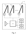
- inventions herein relate to a motor vehicle 30 safety arrangement 10, as schematically illustrated in figure 1 .
- the motor vehicle 30 safety arrangement 10 is provided for positioning a vehicle occupant properly relative to a back rest of a vehicle seat and restraining the vehicle occupant thus positioned on the vehicle seat in preparation of the vehicle 30 potentially being subject to a rear-end collision.
- the motor vehicle 30 has a respective safety belt B 1 , B 2 ...B n associated with each respective vehicle seat.
- a respective electric reversible safety belt retractor R 1 , R 2 ...R n is associated with each respective safety belt B 1 , B 2 ...B n .
- the motor vehicle 30 safety arrangement 10 comprises a rearward-looking detection system D 1 .
- the rearward-looking detection system D 1 is provided for detecting and classifying the collision risk for an approaching object, such as a vehicle approaching the motor vehicle 30 hosting the safety arrangement 10 from behind.
- the rearward-looking detection system D 1 suitably comprises processing means (not shown) arranged to perform the collision risk classification.
- the rearward-looking detection system D 1 comprises one or more of a Radio Detection And Ranging (RADAR) sensor, a Light Detection And Ranging (LIDAR) sensor, a Light Amplification by Stimulated Emission of Radiation (LASER) sensor, an ultrasound sensor, an infrared sensor, an image sensor, or any combination thereof.
- the image sensor may be a video sensor, designed as either a Charge-Coupled Device (CCD) camera or a Complementary Metal-Oxide Semiconductor (CMOS) camera, for example.
- CCD Charge-Coupled Device
- CMOS Complementary Metal-Oxide Semiconductor
- the rearward-looking detection system D 1 is arranged to estimate a time to collision and classify the collision risk for an approaching object as high when the estimated time to collision falls below a predetermined threshold.
- the safety arrangement 10 further comprises at least one sensor S 1 , S 2 ...S n , for monitoring one or more vehicle parameters.
- the at least one sensor S 1 , S 2 ...S n is arranged to monitor at least one of the following vehicle parameters: vehicle velocity, steering wheel angle, vehicle yaw rate, yawing acceleration, lateral acceleration, angle of inclination and wheel speeds.
- a control unit 20 is also comprised in the safety arrangement 10.
- the control unit 20 suitably comprises a processing unit, such as a computer processor, and appropriate software for controlling operation thereof.
- This control unit 20 is arranged to determine a driving state as critical or non-critical from the monitored vehicle parameters.
- the control unit 20 is arranged to determine critical driving from the monitored vehicle parameters when one or more of the vehicle parameters indicate: a low wheel to road friction coefficient, significant vehicle deceleration, vehicle lane change or strong vehicle turning.
- control unit 20 is arranged to determine a low wheel to road friction based on at least differences in the monitored wheel speeds.
- control unit 20 is arranged to determine significant vehicle deceleration based on at least a reduction of the monitored vehicle velocity exceeding a predetermined threshold during a predetermined time interval. This may e.g. be performed through the computer processor being arranged to continuously monitor the vehicle speed. If the vehicle speed reduces by more than X meters per second within a time interval of Y seconds, then a significant vehicle deceleration is detected.
- control unit 20 is arranged to determine vehicle lane change or strong vehicle turning based on at least one of the monitored steering wheel angle and vehicle yaw rate exceeding predetermined thresholds.
- the control unit 20 is further operable to control each electric reversible safety belt retractor R 1 , R 2 ...R n to apply a predetermined pullback force on each respective associated safety belt B 1 , B 2 ...B n , in order to pull an occupant into the vehicle seat in response to the collision risk for an approaching object being classified as high within a predetermined time of an indicated critical driving state.
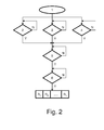
- FIG. 2 A schematic illustration of a method for positioning a vehicle 30 occupant properly relative to a back rest of a vehicle seat and restraining the occupant thus positioned on the vehicle seat in preparation of the vehicle 30 potentially being subject to a rear-end collision is schematically illustrated in figure 2 .
- the method is applicable to a vehicle 30 having a respective safety belt B 1 , B 2 ...B n associated with a respective vehicle seat and a respective electric reversible safety belt retractor R 1 , R 2 ... R n associated with each respective safety belt B 1 , B 2 ... B n .
- the method is initiated as a first step 1.
- the method comprises steps 2, 3, 4 of monitoring one or more vehicle parameters using at least one sensor S 1 , S 2 ...S n .
- figure 2 illustrates an embodiment where in step 2 is decided if a low wheel to road friction coefficient is present, in step 3 is decided if significant vehicle deceleration has occurred and in step 4 is decided if vehicle lane change or strong vehicle turning has occurred, where all of the above is decided from the monitored vehicle parameters.
- the method comprises arranging the at least one sensor S 1 , S 2 ...S n to monitor at least one of the following vehicle parameters: vehicle velocity, steering wheel angle, vehicle yaw rate, yawing acceleration, lateral acceleration, angle of inclination and wheel speeds.
- a step 5 of detecting and classifying the collision risk for an approaching object is performed using a rearward-looking detection system D 1 .
- the method comprises arranging to the rearward-looking detection system D 1 one or more of a radar sensor, a laser sensor, a lidar sensor, an ultrasound sensor, an infrared sensor, an image sensor, or any combination thereof.
- the method further comprises arranging the rearward-looking detection system D 1 to estimate a time to collision and classify the collision risk for an approaching object as high when the estimated time to collision falls below a predetermined threshold.
- a further step 6 of determining a driving state as critical or non-critical from the monitored vehicle parameters and controlling the electric reversible safety belt retractor R 1 , R 2 ...R n to apply a predetermined pullback force on the safety belt B 1 , B 2 ...B n to pull an occupant into the vehicle seat in response to the collision risk for an approaching object being classified as high within a predetermined time of an indicated critical driving state is performed using a control unit 20.
- the method further comprises arranging the control unit 20 to determine critical driving from the monitored vehicle parameters when one or more of the vehicle parameters indicate: a low wheel to road friction coefficient, significant vehicle deceleration, vehicle lane change or strong vehicle turning.
- the method also comprises arranging the control unit 20 to determine a low wheel to road friction coefficient based on at least differences in the monitored wheel speeds.
- the method further comprises arranging the control unit 20 to determine significant vehicle deceleration based on at least a reduction of the monitored vehicle velocity exceeding a predetermined threshold during a predetermined time interval.
- the method further comprises arranging the control unit 20 to determine vehicle lane change or strong vehicle turning based on at least one of the monitored steering wheel angle and vehicle yaw rate exceeding predetermined thresholds.
- a motor vehicle 30 that comprises a motor vehicle safety arrangement 10 as described herein.
Landscapes
- Engineering & Computer Science (AREA)
- Mechanical Engineering (AREA)
- Radar, Positioning & Navigation (AREA)
- Remote Sensing (AREA)
- Automation & Control Theory (AREA)
- Automotive Seat Belt Assembly (AREA)
- Traffic Control Systems (AREA)
Abstract
Description
- Embodiments herein relate to a motor vehicle safety arrangement for positioning an occupant properly relative to a back rest of a vehicle seat and restraining the occupant thus positioned on the vehicle seat in preparation of the vehicle potentially being subject to a rear-end collision.
- Further embodiments herein relate to a method for positioning a vehicle occupant properly relative to a back rest of a vehicle seat and restraining the occupant thus positioned on the vehicle seat in preparation of the vehicle potentially being subject to a rear-end collision.
- Still further embodiments herein relate to a motor vehicle comprising a motor vehicle safety arrangement for positioning an occupant properly relative to a back rest of a vehicle seat and restraining the occupant thus positioned on the vehicle seat in preparation of the vehicle potentially being subject to a rear-end collision.
- In motor vehicles, collision warning systems are becoming more widely used. Collision warning systems provide a vehicle operator knowledge and awareness of objects or vehicles within a close proximity, so as to prevent colliding with those objects. Current collision warning systems usually rely on a sensor located on the vehicle which, upon sensing an object generates an object detection signal, which is communicated to the operator of that vehicle as a warning of a potential collision.
- One class of such collision warning system is a rear-end collision warning system. Rear-end collisions may cause so called whiplash injuries to occupants of the vehicle being rear-ended. Thus, there exist today systems for preventing or mitigating whiplash related injuries during rear-end collisions. Such systems usually rely on electric reversible seat-belt retractors or tensioners. One such system is known through
WO2008002756 , which relates to a control system for warning a following vehicle of a potential collision with a leading vehicle. - In
WO2008002756 the leading vehicle is equipped with a rear collision warning system that can determine the range and range rate of the following vehicle using radar sensors or ultrasonic sensors. The control system employs an algorithm that detects the following vehicle and determines whether the potential exists for a collision with the leading vehicle. The algorithm compares a desired distance between the leading vehicle and the following vehicle based on the speed of the leading vehicle, and determines whether the difference between the desired distance and the actual distance is greater than a predetermined threshold. If the difference is greater than the threshold, the algorithm may provide one or more operations, such as flashing hazard lights to warn the following vehicle, or taking other courses of action in the event of an imminent collision, such as pre-tensioning seat belts. - However, it is a well-known fact that many vehicle drivers have a quite aggressive style of driving. Such aggressive driving increases the number of instances when a driver comes close to a rear-end collision. Known systems, as e.g. the system known through
WO2008002756 , may therefore falsely classify these instances as instances where a collision is imminent. - As a consequence thereof known systems equipped with electric reversible seat-belt retractors or tensioners therefore are often set to activate the retractors or tensioners at a very late instance prior to a rear-end collision, in order to avoid a too frequent activation thereof which may cause a disturbance and be perceived as annoying by vehicle occupants.
- However, rear-end collisions between two moving vehicles often occurs very rapidly, why such late activation may provide for an insufficient amount of time for such known systems to be able to fully accomplish appropriate positioning of a vehicle occupant in order to affect adequate protection against injuries, such as e.g. whiplash injuries.
- Several attempts have been made to ensure that instances of non-threatening driving are not falsely classified as instances where a collision is imminent. One such attempt is illustrated by
US6758495 , which relates to a method and system for restraining an occupant on a vehicle seat, the occupant being pulled into the vehicle seat is provided with a force by a belt tensioner when a critical driving state is detected and then held in a pulled-back position on the vehicle seat with a holding force. A forward-looking detection system for a dangerous driving state is provided, in which, when a dangerous driving state is detected, a belt tensioner is subjected to a force and the occupant is thereby pulled into the vehicle seat, and in which the occupant is held in a pulled-back position on the vehicle seat. - According to
US6758495 a trigger criterion for belt tensioners can thus be derived by determining critical driving situations and/or with the aid of the forward-looking sensor system. The critical vehicle state is detected by monitoring the steering angle, distance from an object, relative velocity, vehicle deceleration, yaw angle, yaw rate, yawing acceleration, vehicle's own speed, steering angle, sharp changes in direction, jump in the road/tire friction coefficient, lateral acceleration, wheel speed and/or angle of inclination or any combination of these parameters. Using the distance from the object, the relative velocity, vehicle's own speed, vehicle deceleration or even the friction coefficient as parameters, for example, a time of collision is determined from this, i.e. the time the electrical reversible belt tensioner has to spare before the time of collision. All the data from detection devices and calculation units or any combination of these data are fed to a control unit, which then compares them with predetermined limiting values and triggers the reversible belt tensioner if these values are exceeded. - Although the method and system suggested by
US6758495 may provide for improved classification of driving instances as non-threatening or threatening there is no provision for ensuring an allowance of a sufficient amount of time to be able to fully accomplish appropriate positioning of a vehicle occupant in order to affect adequate protection against whiplash injuries. - Embodiments herein aim to provide an improved motor vehicle safety arrangement for positioning an occupant properly relative to a back rest of a vehicle seat and restraining the occupant thus positioned on the vehicle seat in preparation of the vehicle potentially being subject to a rear-end collision, the vehicle having a safety belt associated with the vehicle seat and an electric reversible safety belt retractor associated with the safety belt.
- This is provided through a motor vehicle safety arrangement which comprises: a rearward-looking detection system for detecting and classifying the collision risk for an approaching object; at least one sensor for monitoring one or more vehicle parameters ; a control unit arranged to determine a driving state as critical or non-critical from the monitored vehicle parameters; and; where the control unit further is operable to control the electric reversible safety belt retractor to apply a predetermined pullback force on the safety belt to pull an occupant into the vehicle seat in response to the collision risk for an approaching object being classified as high within a predetermined time of an indicated critical driving state.
- The provision a motor vehicle safety arrangement as above, performing belt retraction in response to the collision risk for an approaching object being classified as high within a predetermined time of an indicated critical driving state provides for taking into account driver behavior, such that the number of non-threatening instances being classified as instances where a collision is imminent can be reduced.
- According to a second aspect at least one sensor is arranged to monitor at least one of the following vehicle parameters: vehicle velocity, steering wheel angle, vehicle yaw rate, yawing acceleration, lateral acceleration, angle of inclination and wheel speeds.
- The provision of monitoring these vehicle parameters facilitates cost efficient realization of the arrangement as a plurality of these sensors are normally already present in today's vehicles.
- According to a third aspect the control unit is arranged to determine critical driving from the monitored vehicle parameters when one or more of the vehicle parameters indicate: a low wheel to road friction coefficient, significant vehicle deceleration, vehicle lane change or strong vehicle turning.
- The provision of determining critical driving in this way also facilitates cost efficient realization of the arrangement as determination can be made from vehicle parameters obtained using sensors that are normally already present in today's vehicles.
- According to a fourth aspect the control unit is arranged to determine a low wheel to road friction coefficient based on at least differences in the monitored wheel speeds.
- The provision of determining a low wheel to road friction coefficient in this way also facilitates cost efficient realization of the arrangement as determination can be made from vehicle parameters obtained using wheel speed sensors that are normally already present in today's vehicles.
- According to a fifth aspect the control unit is arranged to determine significant vehicle deceleration based on at least a reduction of the monitored vehicle velocity exceeding a predetermined threshold during a predetermined time interval.
- Determining significant vehicle deceleration in this way is simple and cost efficient as determination can be made from vehicle parameters obtained using sensors that are normally already present in today's vehicles.
- According to a sixth aspect the control unit is arranged to determine vehicle lane change or strong vehicle turning based on at least one of the monitored steering wheel angle and vehicle yaw rate exceeding predetermined thresholds.
- Determining vehicle lane change or strong vehicle turning in this way is simple and cost efficient as determination can be made from vehicle parameters obtained using sensors that are normally already present in today's vehicles.
- According to a seventh aspect the rearward-looking detection system comprises one or more of a radar sensor, a laser sensor, a lidar sensor, an ultrasound sensor, an infrared sensor, an image sensor, or any combination thereof.
- The provision of a rearward-looking detection system of this kind provides for reliable detection of objects approaching the vehicle from behind.
- According to an eight aspect the rearward-looking detection system is arranged to estimate a time to collision and classify the collision risk for an approaching object as high when the estimated time to collision falls below a predetermined threshold.
- Estimating a time to collision and performing classification based on a predetermined threshold for this time to collision provides for a simple and reliable classification of the collision risk for an approaching object.
- According to a ninth aspect is further provided a method for positioning a vehicle occupant properly relative to a back rest of a vehicle seat and restraining the occupant thus positioned on the vehicle seat in preparation of the vehicle potentially being subject to a rear-end collision, the vehicle having a safety belt associated with the vehicle seat and an electric reversible safety belt retractor associated with the safety belt, where the method comprises the steps of: detecting and classifying the collision risk for an approaching object using a rearward-looking detection system; monitoring one or more vehicle parameters using at least one sensor; determining a driving state as critical or non-critical from the monitored vehicle parameters using a control unit; and controlling the electric reversible safety belt retractor to apply a predetermined pullback force on the safety belt to pull an occupant into the vehicle seat in response to the collision risk for an approaching object being classified as high within a predetermined time of an indicated critical driving state using the control unit.
- The provision of a method for positioning a vehicle occupant as above provides for reducing the number of non-threatening instances being classified as instances where a collision is imminent.
- According to a tenth aspect a motor vehicle is provided which comprises a motor vehicle safety arrangement as described herein.
- A motor vehicle comprising a motor vehicle safety arrangement as described herein will provide improved safety for vehicle occupants as through ensuring an allowance of a sufficient amount of time to be able to fully accomplish appropriate positioning of a vehicle occupant in order to affect adequate protection against whiplash injuries should the vehicle be at high risk of being subject to a rear-end collision.
- In the following, embodiments herein will be described in greater detail by way of example only with reference to attached drawings, in which
-
Fig. 1 is a schematic illustration of motor vehicle safety arrangement according to embodiments hereof. -
Fig. 2 is a schematic illustration of a method for positioning a vehicle occupant properly relative to a back rest of a vehicle seat and restraining the occupant thus positioned according to embodiments hereof. -
Fig. 3 is a schematic illustration of a motor vehicle comprising a motor vehicle safety arrangement according to embodiments hereof. - Still other objects and features of embodiments herein will become apparent from the following detailed description considered in conjunction with the accompanying drawings. It is to be understood, however, that the drawings are designed solely for purposes of illustration and not as a definition of the limits hereof, for which reference should be made to the appended claims. It should be further understood that the drawings are not necessarily drawn to scale and that, unless otherwise indicated, they are merely intended to conceptually illustrate the structures and procedures described herein.
- In overview, embodiments herein relate to a
motor vehicle 30safety arrangement 10, as schematically illustrated infigure 1 . Themotor vehicle 30safety arrangement 10 is provided for positioning a vehicle occupant properly relative to a back rest of a vehicle seat and restraining the vehicle occupant thus positioned on the vehicle seat in preparation of thevehicle 30 potentially being subject to a rear-end collision. - The
motor vehicle 30 has a respective safety belt B1, B2...Bn associated with each respective vehicle seat. A respective electric reversible safety belt retractor R1, R2...Rn is associated with each respective safety belt B1, B2...Bn. - The
motor vehicle 30safety arrangement 10 comprises a rearward-looking detection system D1. The rearward-looking detection system D1 is provided for detecting and classifying the collision risk for an approaching object, such as a vehicle approaching themotor vehicle 30 hosting thesafety arrangement 10 from behind. The rearward-looking detection system D1 suitably comprises processing means (not shown) arranged to perform the collision risk classification. - In some embodiments hereof the rearward-looking detection system D1 comprises one or more of a Radio Detection And Ranging (RADAR) sensor, a Light Detection And Ranging (LIDAR) sensor, a Light Amplification by Stimulated Emission of Radiation (LASER) sensor, an ultrasound sensor, an infrared sensor, an image sensor, or any combination thereof. The image sensor may be a video sensor, designed as either a Charge-Coupled Device (CCD) camera or a Complementary Metal-Oxide Semiconductor (CMOS) camera, for example.
- In further embodiments hereof the rearward-looking detection system D1 is arranged to estimate a time to collision and classify the collision risk for an approaching object as high when the estimated time to collision falls below a predetermined threshold.
- The
safety arrangement 10 further comprises at least one sensor S1, S2...Sn, for monitoring one or more vehicle parameters. In embodiments hereof the at least one sensor S1, S2...Sn is arranged to monitor at least one of the following vehicle parameters: vehicle velocity, steering wheel angle, vehicle yaw rate, yawing acceleration, lateral acceleration, angle of inclination and wheel speeds. The person skilled in the art will immediately recognize that determination of one or more of the above vehicle parameters can be made using sensors that are normally already present in today's vehicles. Thus, thesafety arrangement 10 may re-use sensors already present for simplicity and cost efficiency. - A
control unit 20 is also comprised in thesafety arrangement 10. Thecontrol unit 20 suitably comprises a processing unit, such as a computer processor, and appropriate software for controlling operation thereof. Thiscontrol unit 20 is arranged to determine a driving state as critical or non-critical from the monitored vehicle parameters. In embodiments hereof thecontrol unit 20 is arranged to determine critical driving from the monitored vehicle parameters when one or more of the vehicle parameters indicate: a low wheel to road friction coefficient, significant vehicle deceleration, vehicle lane change or strong vehicle turning. - In this way it is possible to position a vehicle occupant properly immediately after a high-risk maneuver has been performed and there exist a threat of suffering a rear end collision. Thus, if either low wheel to road friction, significant vehicle deceleration, vehicle lane change or right or left turn is detected within the last T seconds and an object, e.g. a second vehicle, is detected which is approaching from the rear and has a Time to Collision of less than Z seconds, then the electrical reversible retractors R1, R2...Rn are activated to position the passengers of the
vehicle 30 in preparation of thevehicle 30 potentially being hit from behind. - In some embodiments hereof the
control unit 20 is arranged to determine a low wheel to road friction based on at least differences in the monitored wheel speeds. - In yet further embodiments hereof the
control unit 20 is arranged to determine significant vehicle deceleration based on at least a reduction of the monitored vehicle velocity exceeding a predetermined threshold during a predetermined time interval. This may e.g. be performed through the computer processor being arranged to continuously monitor the vehicle speed. If the vehicle speed reduces by more than X meters per second within a time interval of Y seconds, then a significant vehicle deceleration is detected. - In still further embodiments hereof the
control unit 20 is arranged to determine vehicle lane change or strong vehicle turning based on at least one of the monitored steering wheel angle and vehicle yaw rate exceeding predetermined thresholds. - The
control unit 20 is further operable to control each electric reversible safety belt retractor R1, R2...Rn to apply a predetermined pullback force on each respective associated safety belt B1, B2...Bn, in order to pull an occupant into the vehicle seat in response to the collision risk for an approaching object being classified as high within a predetermined time of an indicated critical driving state. - A schematic illustration of a method for positioning a
vehicle 30 occupant properly relative to a back rest of a vehicle seat and restraining the occupant thus positioned on the vehicle seat in preparation of thevehicle 30 potentially being subject to a rear-end collision is schematically illustrated infigure 2 . - The method is applicable to a
vehicle 30 having a respective safety belt B1, B2...Bn associated with a respective vehicle seat and a respective electric reversible safety belt retractor R1, R2... Rn associated with each respective safety belt B1, B2... Bn. - In accordance with the proposed method for positioning a
vehicle 30 occupant the method is initiated as afirst step 1. - Once up and running the method comprises
steps - For simplicity,
figure 2 illustrates an embodiment where instep 2 is decided if a low wheel to road friction coefficient is present, instep 3 is decided if significant vehicle deceleration has occurred and instep 4 is decided if vehicle lane change or strong vehicle turning has occurred, where all of the above is decided from the monitored vehicle parameters. - In embodiments hereof the method comprises arranging the at least one sensor S1, S2...Sn to monitor at least one of the following vehicle parameters: vehicle velocity, steering wheel angle, vehicle yaw rate, yawing acceleration, lateral acceleration, angle of inclination and wheel speeds.
- A
step 5 of detecting and classifying the collision risk for an approaching object is performed using a rearward-looking detection system D1. In embodiments hereof the method comprises arranging to the rearward-looking detection system D1 one or more of a radar sensor, a laser sensor, a lidar sensor, an ultrasound sensor, an infrared sensor, an image sensor, or any combination thereof. - In embodiments hereof the method further comprises arranging the rearward-looking detection system D1 to estimate a time to collision and classify the collision risk for an approaching object as high when the estimated time to collision falls below a predetermined threshold.
- A
further step 6 of determining a driving state as critical or non-critical from the monitored vehicle parameters and controlling the electric reversible safety belt retractor R1, R2...Rn to apply a predetermined pullback force on the safety belt B1, B2...Bn to pull an occupant into the vehicle seat in response to the collision risk for an approaching object being classified as high within a predetermined time of an indicated critical driving state is performed using acontrol unit 20. - In some embodiments the method further comprises arranging the
control unit 20 to determine critical driving from the monitored vehicle parameters when one or more of the vehicle parameters indicate: a low wheel to road friction coefficient, significant vehicle deceleration, vehicle lane change or strong vehicle turning. - In further embodiments the method also comprises arranging the
control unit 20 to determine a low wheel to road friction coefficient based on at least differences in the monitored wheel speeds. - Also, in some embodiments the method further comprises arranging the
control unit 20 to determine significant vehicle deceleration based on at least a reduction of the monitored vehicle velocity exceeding a predetermined threshold during a predetermined time interval. - In yet some embodiments the method further comprises arranging the
control unit 20 to determine vehicle lane change or strong vehicle turning based on at least one of the monitored steering wheel angle and vehicle yaw rate exceeding predetermined thresholds. - According to the present application is also envisaged a
motor vehicle 30 that comprises a motorvehicle safety arrangement 10 as described herein. - The above-described embodiments may be varied within the scope of the following claims.
- Thus, while there have been shown and described and pointed out fundamental novel features of the embodiments herein, it will be understood that various omissions and substitutions and changes in the form and details of the devices illustrated, and in their operation, may be made by those skilled in the art. For example, it is expressly intended that all combinations of those elements and/or method steps which perform substantially the same function in substantially the same way to achieve the same results are equivalent. Moreover, it should be recognized that structures and/or elements and/or method steps shown and/or described in connection with any disclosed form or embodiment herein may be incorporated in any other disclosed or described or suggested form or embodiment as a general matter of design choice.
Claims (10)
- A motor vehicle (30) safety arrangement (10) for positioning an occupant properly relative to a back rest of a vehicle seat and restraining the occupant thus positioned on the vehicle seat in preparation of the vehicle (30) potentially being subject to a rear-end collision, the vehicle (30) having a safety belt (B1, B2...Bn) associated with the vehicle seat and an electric reversible safety belt retractor (R1, R2...Rn) associated with the safety belt (B1, B2...Bn),
characterized in that it comprises:a rearward-looking detection system (D1) for detecting and classifying the collision risk for an approaching object;at least one sensor (S1, S2...Sn) for monitoring one or more vehicle parameters;a control unit (20) arranged to determine a driving state as critical or non-critical from the monitored vehicle parameters; andwhere the control unit (20) further is operable to control the electric reversible safety belt retractor (R1, R2...Rn) to apply a predetermined pullback force on the safety belt (B1, B2...Bn) to pull an occupant into the vehicle seat in response to the collision risk for an approaching object being classified as high within a predetermined time of an indicated critical driving state. - A motor vehicle (30) safety arrangement (10) according to claim 1, characterized in that the at least one sensor (S1, S2...Sn) is arranged to monitor at least one of the following vehicle parameters: vehicle velocity, steering wheel angle, vehicle yaw rate, yawing acceleration, lateral acceleration, angle of inclination and wheel speeds.
- A motor vehicle (30) safety arrangement (10) according to claim 2, characterized in that the control unit (20) is arranged to determine critical driving from the monitored vehicle parameters when one or more of the vehicle parameters indicate: a low wheel to road friction coefficient, significant vehicle deceleration, vehicle lane change or strong vehicle turning.
- A motor vehicle (30) safety arrangement (10) according to claim 3, characterized in that the control unit (20) is arranged to determine a low wheel to road friction coefficient based on at least differences in the monitored wheel speeds.
- A motor vehicle (30) safety arrangement (10) according to any one of claims 3 or 4, characterized in that the control unit (20) is arranged to determine significant vehicle deceleration based on at least a reduction of the monitored vehicle velocity exceeding a predetermined threshold during a predetermined time interval.
- A motor vehicle (30) safety arrangement (10) according to any one of claims 3 to 5, characterized in that the control unit (20) is arranged to determine vehicle lane change or strong vehicle turning based on at least one of the monitored steering wheel angle and vehicle yaw rate exceeding predetermined thresholds.
- A motor vehicle (30) safety arrangement (10) according to any one of claims 1 to 6, characterized in that the rearward-looking detection system (D1) comprises one or more of a radar sensor, a laser sensor, a lidar sensor, an ultrasound sensor, an infrared sensor, an image sensor, or any combination thereof.
- A motor vehicle (30) safety arrangement (10) according to any one of the preceding claims, characterized in that the rearward-looking detection system (D1) is arranged to estimate a time to collision and classify the collision risk for an approaching object as high when the estimated time to collision falls below a predetermined threshold.
- A method for positioning a vehicle (30) occupant properly relative to a back rest of a vehicle seat and restraining the occupant thus positioned on the vehicle seat in preparation of the vehicle (30) potentially being subject to a rear-end collision, the vehicle (30) further having a safety belt (B1, B2...Bn) associated with the vehicle seat and an electric reversible safety belt retractor (R1, R2...Rn) associated with the safety belt (B1, B2...Bn), characterized in that it comprises the steps of:detecting and classifying the collision risk for an approaching object using a rearward-looking detection system (D1);monitoring one or more vehicle parameters using at least one sensor (S1, S2...Sn);determining a driving state as critical or non-critical from the monitored vehicle parameters using a control unit (20); andcontrolling the electric reversible safety belt retractor (R1, R2...Rn) to apply a predetermined pullback force on the safety belt (B1, B2...Bn) to pull an occupant into the vehicle seat in response to the collision risk for an approaching object being classified as high within a predetermined time of an indicated critical driving state using the control unit (20).
- A motor vehicle (30) characterized in that it comprises a motor vehicle safety arrangement (10) according to any one of claims 1 to 8.
Priority Applications (3)
| Application Number | Priority Date | Filing Date | Title |
|---|---|---|---|
| EP13151989.4A EP2756992A1 (en) | 2013-01-21 | 2013-01-21 | Motor vehicle safety arrangement and method |
| US14/154,491 US9545896B2 (en) | 2013-01-21 | 2014-01-14 | Motor vehicle safety arrangement and method |
| CN201410016225.6A CN103935319A (en) | 2013-01-21 | 2014-01-14 | Motor vehicle safety arrangement and method |
Applications Claiming Priority (1)
| Application Number | Priority Date | Filing Date | Title |
|---|---|---|---|
| EP13151989.4A EP2756992A1 (en) | 2013-01-21 | 2013-01-21 | Motor vehicle safety arrangement and method |
Publications (1)
| Publication Number | Publication Date |
|---|---|
| EP2756992A1 true EP2756992A1 (en) | 2014-07-23 |
Family
ID=47603384
Family Applications (1)
| Application Number | Title | Priority Date | Filing Date |
|---|---|---|---|
| EP13151989.4A Ceased EP2756992A1 (en) | 2013-01-21 | 2013-01-21 | Motor vehicle safety arrangement and method |
Country Status (3)
| Country | Link |
|---|---|
| US (1) | US9545896B2 (en) |
| EP (1) | EP2756992A1 (en) |
| CN (1) | CN103935319A (en) |
Cited By (2)
| Publication number | Priority date | Publication date | Assignee | Title |
|---|---|---|---|---|
| WO2016024899A1 (en) * | 2014-08-13 | 2016-02-18 | Scania Cv Ab | System and method for safety improvement during operation of a motor vehicle |
| CN111098762A (en) * | 2018-10-26 | 2020-05-05 | 现代自动车株式会社 | Pre-active safety regulation control method and device |
Families Citing this family (4)
| Publication number | Priority date | Publication date | Assignee | Title |
|---|---|---|---|---|
| US9963251B2 (en) * | 2015-05-27 | 2018-05-08 | The Aerospace Corporation | Systems and methods for estimating parameters of a spacecraft based on emission from an atomic or molecular product of a plume from the spacecraft |
| EP3260344B1 (en) * | 2016-06-20 | 2021-10-06 | Volvo Car Corporation | Method and system for adjusting a safety margin threshold of a driver support function |
| CN110780602B (en) * | 2019-09-09 | 2022-02-18 | 腾讯科技(深圳)有限公司 | Method, device and equipment for constructing simulated vehicle lane change track |
| CN113200014A (en) * | 2021-05-21 | 2021-08-03 | 上汽通用五菱汽车股份有限公司 | Seat belt prompting method, vehicle and readable storage medium |
Citations (5)
| Publication number | Priority date | Publication date | Assignee | Title |
|---|---|---|---|---|
| US20020105416A1 (en) * | 2001-02-06 | 2002-08-08 | Haruhisa Kore | Occupant protection system for vehicle |
| US6758495B2 (en) | 2000-02-04 | 2004-07-06 | Daimlerchrysler Ag | Method and safety restraint device for restraining an occupant on a vehicle seat |
| EP1783007A1 (en) * | 2005-11-02 | 2007-05-09 | Robert Bosch Gmbh | Method and device for activating occupant protection systems |
| WO2008002756A2 (en) | 2006-06-27 | 2008-01-03 | Gm Global Tecgnology Operations, Inc. | Rear collision warning system |
| JP2008120228A (en) * | 2006-11-10 | 2008-05-29 | Toyota Motor Corp | Rear end collision predicting device |
Family Cites Families (3)
| Publication number | Priority date | Publication date | Assignee | Title |
|---|---|---|---|---|
| DE102004038167B4 (en) * | 2004-08-06 | 2013-03-07 | Daimler Ag | Motor vehicle with a preventive protection system |
| CN102792349B (en) * | 2010-03-16 | 2016-03-30 | 丰田自动车株式会社 | Drive assistance device |
| US8855866B2 (en) * | 2011-11-22 | 2014-10-07 | Continental Automotive Systems, Inc. | Rear end advanced collision technology |
-
2013
- 2013-01-21 EP EP13151989.4A patent/EP2756992A1/en not_active Ceased
-
2014
- 2014-01-14 US US14/154,491 patent/US9545896B2/en active Active
- 2014-01-14 CN CN201410016225.6A patent/CN103935319A/en active Pending
Patent Citations (5)
| Publication number | Priority date | Publication date | Assignee | Title |
|---|---|---|---|---|
| US6758495B2 (en) | 2000-02-04 | 2004-07-06 | Daimlerchrysler Ag | Method and safety restraint device for restraining an occupant on a vehicle seat |
| US20020105416A1 (en) * | 2001-02-06 | 2002-08-08 | Haruhisa Kore | Occupant protection system for vehicle |
| EP1783007A1 (en) * | 2005-11-02 | 2007-05-09 | Robert Bosch Gmbh | Method and device for activating occupant protection systems |
| WO2008002756A2 (en) | 2006-06-27 | 2008-01-03 | Gm Global Tecgnology Operations, Inc. | Rear collision warning system |
| JP2008120228A (en) * | 2006-11-10 | 2008-05-29 | Toyota Motor Corp | Rear end collision predicting device |
Cited By (3)
| Publication number | Priority date | Publication date | Assignee | Title |
|---|---|---|---|---|
| WO2016024899A1 (en) * | 2014-08-13 | 2016-02-18 | Scania Cv Ab | System and method for safety improvement during operation of a motor vehicle |
| US10315560B2 (en) | 2014-08-13 | 2019-06-11 | Scania Cv Ab | System and method for safety improvement during operation of a motor vehicle |
| CN111098762A (en) * | 2018-10-26 | 2020-05-05 | 现代自动车株式会社 | Pre-active safety regulation control method and device |
Also Published As
| Publication number | Publication date |
|---|---|
| US20140207339A1 (en) | 2014-07-24 |
| CN103935319A (en) | 2014-07-23 |
| US9545896B2 (en) | 2017-01-17 |
Similar Documents
| Publication | Publication Date | Title |
|---|---|---|
| EP2484573B1 (en) | Method for reducing the risk of a collision between a vehicle and a first external object | |
| US9545896B2 (en) | Motor vehicle safety arrangement and method | |
| CN104960509B (en) | For minimizing the method that automatic braking is invaded and harassed based on collision confidence level | |
| CN108357492B (en) | Apparatus and method for mitigating forward collisions between road vehicles | |
| CN107010059B (en) | Control system and control method for determining the probability of an imminent collision of a vehicle | |
| US10625735B2 (en) | Vehicle control apparatus and vehicle control method | |
| US8150583B2 (en) | Method and apparatus for avoiding or mitigating vehicle collisions | |
| EP2682318B1 (en) | Motor vehicle collision warning system | |
| EP2913234B1 (en) | Automatic braking for driving in reverse | |
| EP2266022B1 (en) | Enhanced vision road detection system | |
| JP4942642B2 (en) | Method and configuration for controlling safety measures in a vehicle | |
| EP3501911A1 (en) | Apparatus and method for controlling vehicular active seatbelt | |
| US8855866B2 (en) | Rear end advanced collision technology | |
| JP6983915B2 (en) | Rear pre-crash safety system | |
| EP2883743B1 (en) | Apparatus and method for vehicle occupant protection in roadway departure | |
| US20170151937A1 (en) | Vehicle control apparatus | |
| EP2743144A2 (en) | GPS data for improving pedestrian protection | |
| KR100666360B1 (en) | Apparatus for preventing car crash based on vehicle dynamics | |
| US11912127B2 (en) | Method for controlling a vehicle | |
| KR101511862B1 (en) | Driver assistance systems and controlling method for the same | |
| EP2650177B1 (en) | Method for triggering a motorized retractor for a safety belt system of a vehicle | |
| KR20160054927A (en) | Phased collision prevention system | |
| CN115703463A (en) | Apparatus and method for controlling vehicle | |
| KR20230072569A (en) | Vehicle passenger accident prevention system and control method thereof | |
| KR20150097940A (en) | Apparatus for developing of airbag in a vehicle and control method thereof |
Legal Events
| Date | Code | Title | Description |
|---|---|---|---|
| PUAI | Public reference made under article 153(3) epc to a published international application that has entered the european phase |
Free format text: ORIGINAL CODE: 0009012 |
|
| 17P | Request for examination filed |
Effective date: 20130121 |
|
| AK | Designated contracting states |
Kind code of ref document: A1 Designated state(s): AL AT BE BG CH CY CZ DE DK EE ES FI FR GB GR HR HU IE IS IT LI LT LU LV MC MK MT NL NO PL PT RO RS SE SI SK SM TR |
|
| AX | Request for extension of the european patent |
Extension state: BA ME |
|
| R17P | Request for examination filed (corrected) |
Effective date: 20150123 |
|
| RBV | Designated contracting states (corrected) |
Designated state(s): AL AT BE BG CH CY CZ DE DK EE ES FI FR GB GR HR HU IE IS IT LI LT LU LV MC MK MT NL NO PL PT RO RS SE SI SK SM TR |
|
| STAA | Information on the status of an ep patent application or granted ep patent |
Free format text: STATUS: THE APPLICATION HAS BEEN REFUSED |
|
| 18R | Application refused |
Effective date: 20181126 |