EP2752995B1 - Modeling transmitter and/or transmit observation receiver frequency response and utilization thereof - Google Patents
Modeling transmitter and/or transmit observation receiver frequency response and utilization thereof Download PDFInfo
- Publication number
- EP2752995B1 EP2752995B1 EP13005700.3A EP13005700A EP2752995B1 EP 2752995 B1 EP2752995 B1 EP 2752995B1 EP 13005700 A EP13005700 A EP 13005700A EP 2752995 B1 EP2752995 B1 EP 2752995B1
- Authority
- EP
- European Patent Office
- Prior art keywords
- transmitter
- tor
- model
- output
- input
- Prior art date
- Legal status (The legal status is an assumption and is not a legal conclusion. Google has not performed a legal analysis and makes no representation as to the accuracy of the status listed.)
- Active
Links
- 230000004044 response Effects 0.000 title claims description 105
- 238000012549 training Methods 0.000 claims description 41
- 238000012360 testing method Methods 0.000 claims description 39
- 238000000034 method Methods 0.000 claims description 33
- 238000005476 soldering Methods 0.000 description 5
- 230000008569 process Effects 0.000 description 4
- 230000003542 behavioural effect Effects 0.000 description 2
- 239000000969 carrier Substances 0.000 description 2
- 238000007796 conventional method Methods 0.000 description 2
- 238000012986 modification Methods 0.000 description 2
- 230000004048 modification Effects 0.000 description 2
- 230000003044 adaptive effect Effects 0.000 description 1
- 230000009286 beneficial effect Effects 0.000 description 1
- 230000005540 biological transmission Effects 0.000 description 1
- 238000004891 communication Methods 0.000 description 1
- 238000010168 coupling process Methods 0.000 description 1
- 238000005859 coupling reaction Methods 0.000 description 1
- 230000001419 dependent effect Effects 0.000 description 1
- 238000011161 development Methods 0.000 description 1
- 230000018109 developmental process Effects 0.000 description 1
- 230000000694 effects Effects 0.000 description 1
- 230000006870 function Effects 0.000 description 1
- 238000012545 processing Methods 0.000 description 1
Images


Classifications
-
- H—ELECTRICITY
- H04—ELECTRIC COMMUNICATION TECHNIQUE
- H04B—TRANSMISSION
- H04B1/00—Details of transmission systems, not covered by a single one of groups H04B3/00 - H04B13/00; Details of transmission systems not characterised by the medium used for transmission
- H04B1/02—Transmitters
- H04B1/04—Circuits
- H04B1/0475—Circuits with means for limiting noise, interference or distortion
-
- H—ELECTRICITY
- H04—ELECTRIC COMMUNICATION TECHNIQUE
- H04B—TRANSMISSION
- H04B1/00—Details of transmission systems, not covered by a single one of groups H04B3/00 - H04B13/00; Details of transmission systems not characterised by the medium used for transmission
- H04B1/62—Details of transmission systems, not covered by a single one of groups H04B3/00 - H04B13/00; Details of transmission systems not characterised by the medium used for transmission for providing a predistortion of the signal in the transmitter and corresponding correction in the receiver, e.g. for improving the signal/noise ratio
-
- H—ELECTRICITY
- H03—ELECTRONIC CIRCUITRY
- H03F—AMPLIFIERS
- H03F1/00—Details of amplifiers with only discharge tubes, only semiconductor devices or only unspecified devices as amplifying elements
- H03F1/32—Modifications of amplifiers to reduce non-linear distortion
- H03F1/3241—Modifications of amplifiers to reduce non-linear distortion using predistortion circuits
-
- H—ELECTRICITY
- H04—ELECTRIC COMMUNICATION TECHNIQUE
- H04B—TRANSMISSION
- H04B1/00—Details of transmission systems, not covered by a single one of groups H04B3/00 - H04B13/00; Details of transmission systems not characterised by the medium used for transmission
- H04B1/02—Transmitters
- H04B1/04—Circuits
-
- H—ELECTRICITY
- H04—ELECTRIC COMMUNICATION TECHNIQUE
- H04B—TRANSMISSION
- H04B1/00—Details of transmission systems, not covered by a single one of groups H04B3/00 - H04B13/00; Details of transmission systems not characterised by the medium used for transmission
- H04B1/38—Transceivers, i.e. devices in which transmitter and receiver form a structural unit and in which at least one part is used for functions of transmitting and receiving
- H04B1/40—Circuits
-
- H—ELECTRICITY
- H04—ELECTRIC COMMUNICATION TECHNIQUE
- H04B—TRANSMISSION
- H04B1/00—Details of transmission systems, not covered by a single one of groups H04B3/00 - H04B13/00; Details of transmission systems not characterised by the medium used for transmission
- H04B1/02—Transmitters
- H04B1/04—Circuits
- H04B2001/0408—Circuits with power amplifiers
- H04B2001/0425—Circuits with power amplifiers with linearisation using predistortion
Definitions
- the present disclosure relates to modeling a frequency response of a transmitter and/or a frequency response of a transmit observation receiver coupled to an output of the transmitter and utilizing the model(s) to improve performance of the transmitter.
- FIG. 1 illustrates a conventional system 10 that that includes a transmitter 12 and a transmit observation receiver (TOR) 14 coupled to an output of the transmitter 12 via a coupler 16.
- the transmitter 12 includes a digital predistorter (DPD) 18, a Digital-to-Analog Converter (DAC) 20, an upconversion subsystem 22, and a power amplifier (PA) 24 connected as shown.
- An output of the transmitter 12 i.e., an output of the PA 24
- TX transmit
- the output of the PA 24 is also coupled to an input of the TOR 14 via the coupler 16.
- the TOR 14 includes a downconversion subsystem 30 and an Analog-to-Digital Converter (ADC) 32 connected as shown.
- ADC Analog-to-Digital Converter
- An output of the TOR 14 is coupled to a first input of a subtractor 34.
- the input of the transmitter 12 is coupled to an input of a delay and gain adjustment component 36, and an output of the delay and gain adjustment component 36 is coupled to a second input of the subtractor 34.
- a baseband processor 38 sends a digital transmit signal to the input of the transmitter 12.
- the digital transmit signal is predistorted by the DPD 18 to compensate for nonlinearity of the PA 24, converted from digital to analog by the DAC 20, upconverted to a desired radio frequency by the upconversion subsystem 22, and amplified by the PA 24 to provide a radio frequency transmit signal at the output of the transmitter 12.
- the radio frequency transmit signal is filtered by the transmit filter 28, and the resulting filtered radio frequency transmit signal is transmitted via the antenna 26.
- the TOR 14 samples the radio frequency transmit signal output by the transmitter 12 to provide a digital TOR output signal at the output of the TOR 14.
- the subtractor 34 then subtracts a gain and delay adjusted version of the digital transmit signal input to the transmitter 12 from the digital TOR output signal to provide an error signal that represents a residual InterModulation Distortion (IMD) in the radio frequency transmit signal output by the transmitter 12.
- the error signal can then be utilized by the baseband processor 38 to, for example, adaptively configure the DPD 18 to compensate for the nonlinearity of the PA 24.
- the delay and gain adjustment component 36 can accurately model a path between the input of the transmitter 12 and the output of the TOR 14 for conventional transmit signals. However, for modern and future wireless communications standards, the transmit signals have or will have significantly wider bandwidths. For wideband transmit signals, the delay and gain adjustment component 36 is not capable of accurately modeling the path between the input of the transmitter 12 and the output of the TOR 14. In particular, the delay and gain adjustment component 36 is not capable of accurately modeling a path between the output of the transmitter 12 and the output of the TOR 14 for wideband transmit signals. More specifically, a frequency response of the TOR 14 varies significantly over the bandwidth of the wideband transmit signals.
- the performance of the transmitter 12 will suffer (e.g., the baseband processor 38 will take longer to adapt the DPD 18). As such, there is a need for a model of the frequency response of the TOR 14 for wideband transmit signals.
- a transmitter includes a power amplifier configured to amplify a radio frequency input signal to provide an amplified radio frequency signal, a non-linear filter configured to filter the amplified radio frequency signal to provide an output signal of the transmitter, and a predistorter configured effect predistortion of the amplified radio frequency signal, where the predistortion compensates for a non-linear characteristic of the non-linear filter.
- the output signal is as if the non-linear filter were a linear, or substantially liner, filter.
- the predistortion applied by the predistorter may be fixed or adaptive.
- Systems and methods for training, or calibrating, a model of a frequency response of a transmitter and/or a model of a frequency response of a transmit observation receiver (TOR) coupled to an output of the transmitter are disclosed.
- a nonlinear component is connected between an output of the transmitter and an input of the TOR.
- a combined model for the frequency response of the transmitter, a nonlinear characteristic of the nonlinear component, and the frequency response of the TOR is then trained.
- the combined model is a concatenation of a first linear filter (H 1 (z)) that is a model of the frequency response of the transmitter, a quasi-memoryless nonlinearity (f( ⁇ )) that is a model of the nonlinear characteristic of the nonlinear component, and a second linear filter (H 2 (z)) that is a model of the frequency response of the TOR.
- the combined model is a three-box model known as a Wiener-Hammerstein model.
- the nonlinear component is disconnected for normal operation of the transmitter and the TOR.
- systems and methods for utilizing a model of a frequency response of a transmitter and/or a model of a frequency response of a TOR coupled to an output of the transmitter to improve a performance of the transmitter are disclosed.
- an inverse of the model of the frequency response of the TOR is applied to an output signal of the TOR during normal operation.
- an inverse of the model of the frequency response of the transmitter is applied to an input signal of the transmitter during normal operation.
- Systems and methods for training, or calibrating, a model of a frequency response of a transmitter and/or a model of a frequency response of a transmit observation receiver (TOR) coupled to an output of the transmitter are disclosed.
- TOR transmit observation receiver
- two exemplary systems for utilizing the models to improve performance of a transmitter are disclosed. Note, however, that these systems for utilizing the models are only examples and are not intended to limit the scope of the present disclosure.
- Figure 2 illustrates a system 40 that includes a transmitter 42 and a TOR 44 coupled to an output of the transmitter 42 via a coupler 46, wherein a model of a frequency response of the TOR 44 is utilized to improve a performance of the transmitter 42 according to one embodiment of the present disclosure.
- a TOR inverse model component 48 applies an inverse of the model of a frequency response of the TOR 44 to a digital TOR output signal output by the TOR 44 to thereby frequency equalize the frequency response of the TOR 44.
- performance of the transmitter 42 is substantially improved.
- the transmitter 42 includes a digital predistorter (DPD) 50, a Digital-to-Analog Converter (DAC) 52, an upconversion subsystem 54, and a power amplifier (PA) 56 connected as shown.
- DPD digital predistorter
- DAC Digital-to-Analog Converter
- PA power amplifier
- An output of the transmitter 42 i.e., an output of the PA 56
- TX transmit
- the output of the PA 56 is also coupled to an input of the TOR 44 via the coupler 46.
- the TOR 44 includes a downconversion subsystem 62 and an Analog-to-Digital Converter (ADC) 64 connected as shown.
- ADC Analog-to-Digital Converter
- An output of the TOR 44 is coupled to an input of the TOR inverse model component 48, and an output of the TOR inverse model component 48 is coupled to a first input of a subtractor 66.
- the input of the transmitter 42 is coupled to an input of a delay and gain adjustment component 68, and an output of the delay and gain adjustment component 68 is coupled to a second input of the subtractor 66.
- the TOR inverse model component 48 is illustrated as a separate block in Figure 2
- the TOR inverse model component 48 (and the subtractor 66 and the delay and gain adjustment component 68) may alternatively be implemented within a baseband processor 70.
- the baseband processor 70 sends a digital transmit signal to the input of the transmitter 42.
- the digital transmit signal is predistorted by the DPD 50 to compensate for nonlinearity of the PA 56, converted from digital to analog by the DAC 52, upconverted to a desired radio frequency by the upconversion subsystem 54, and amplified by the PA 56 to provide a radio frequency transmit signal at the output of the transmitter 42.
- the radio frequency transmit signal is filtered by the transmit filter 60, and the resulting filtered radio frequency transmit signal is transmitted via the antenna 58.
- the TOR 44 samples the radio frequency transmit signal output by the transmitter 42 to provide a digital TOR output signal at the output of the TOR 44.
- the radio frequency transmit signal obtained from the output of the PA 56 via the coupler 46 is downconverted, preferably to baseband, by the downconversion subsystem 62 and analog to digital converted by the ADC 64 to thereby provide the digital TOR output signal at the output of the TOR 44.
- the digital TOR output signal is passed through the TOR inverse model component 48 to provide a frequency-equalized digital TOR output signal.
- the frequency-equalized digital TOR output signal is as if the frequency response of the TOR 44 were flat, or essentially flat, over a desired observation bandwidth.
- a "frequency-equalized" signal such as the frequency-equalized digital TOR output signal, refers to a signal that has passed through a channel with a flat response over the desired bandwidth.
- a "flat" response refers to a magnitude response and a group delay response, which are independent of frequency.
- the desired observation bandwidth is a bandwidth of a desired transmit signal within the radio frequency transmit signal output by the transmitter 42. However, the desired observation bandwidth is not limited thereto.
- the delay and gain adjustment component 68 applies delay and gain adjustments to the digital transmit signal to provide an adjusted digital transmit signal.
- the delay and gain adjustments are configured to model a path from the input of the transmitter 42 to the output of the transmitter 42.
- the subtractor 66 subtracts the adjusted digital transmit signal from the frequency-equalized digital TOR output signal to provide an error signal that represents a residual InterModulation Distortion (IMD) in the radio frequency transmit signal output by the transmitter 42.
- the error signal is provided to the baseband processor 70 where the error signal is utilized to adaptively configure the DPD 50 to compensate for the nonlinearity of the PA 56 by minimizing, or at least reducing, the residual IMD.
- Figure 3 illustrates a system 72 that includes a transmitter 74 and a TOR 76 coupled to an output of the transmitter 74 via a coupler 78, wherein a model of a frequency response of the transmitter 74 is utilized to improve a performance of the transmitter 74 according to one embodiment of the present disclosure.
- a transmitter inverse model component 80 applies an inverse of the model of a frequency response of the transmitter 74 to a digital transmit signal input to the transmitter 74 to thereby frequency equalize the frequency response of the transmitter 74.
- performance of the transmitter 74 is substantially improved.
- the transmitter 74 includes a DAC 82, an upconversion subsystem 84, and a PA 86 connected as shown.
- the transmitter 74 may include a DPD prior to the DAC 82.
- An output of the transmitter 74 i.e., an output of the PA 86
- the output of the PA 86 is also coupled to an input of the TOR 76 via the coupler 78.
- the TOR 76 includes a downconversion subsystem 92 and an ADC 94 connected as shown. In this embodiment, an output of the TOR 76 is coupled to an input of a baseband processor 96.
- the baseband processor 96 sends a digital transmit signal to an input of the transmitter inverse model component 80.
- the transmitter inverse model component 80 passes the digital transmit signal through an inverse of a model of the frequency response of the transmitter 74 to thereby provide an adjusted digital transmit signal at an output of the transmitter inverse model component 80.
- the output of the transmitter 74 is frequency-equalized.
- the transmitter inverse model component 80 is illustrated as a separate block in Figure 3 , the transmitter inverse model component 80 may alternatively be implemented within the baseband processor 96.
- the adjusted digital transmit signal is converted from digital to analog by the DAC 82, upconverted to a desired radio frequency by the upconversion subsystem 84, and amplified by the PA 86 to provide a radio frequency transmit signal at the output of the transmitter 74.
- the radio frequency transmit signal is filtered by the transmit filter 90, and the resulting filtered radio frequency transmit signal is transmitted via the antenna 88.
- the radio frequency transmit signal is as if the frequency response of the transmitter 74 were flat, or essentially flat, over a desired transmit bandwidth.
- the desired transmit bandwidth is a bandwidth of a desired transmit signal within the radio frequency transmit signal output by the transmitter 74.
- the TOR 76 samples the radio frequency transmit signal output by the transmitter 74 to provide a digital TOR output signal at the output of the TOR 76. More specifically, the radio frequency transmit signal obtained from the output of the PA 86 via the coupler 78 is downconverted, preferably to baseband, by the downconversion subsystem 92 and analog to digital converted by the ADC 94 to thereby provide the digital TOR output signal at the output of the TOR 76.
- the baseband processor 96 then utilizes the digital TOR output signal to provide a desired function. As one example, the digital TOR output signal may be used to adapt a digital predistortion subsystem of the transmitter 74.
- the digital predistortion subsystem may be used to linearize the transmitter 74 (e.g., compensate for a nonlinearity of the transmitter 74 such as, for instance, a nonlinearity of the PA 86).
- the digital TOR output signal may be used to measure the frequency response of the transmitter 74.
- the transmitter inverse model component 80 of Figure 3 may be particularly beneficial for PA architectures where the PA 86 includes multiple parallel amplifier branches (e.g., a Doherty amplifier architecture).
- the paths, or branches, of the PA 86 can be frequency-equalized in the digital domain using the inverse of both of their transmitter frequency responses. Equalizing these paths improves performance especially as signal bandwidth increases.
- the model of the frequency response of the TOR 44 must be trained, or calibrated.
- the model of the frequency response of the transmitter 74 must be trained, or calibrated.
- conventional techniques used to measure the frequency response of a channel, or path, that starts and ends in the digital domain are incapable of isolating the frequency response of the transmitter 42, 74 from the frequency response of the TOR 44, 76 unless either the frequency response of the transmitter 42, 74 or the frequency response of the TOR 44, 76 is already known.
- calibrated radio frequency test equipment e.g., a calibrated radio frequency receiver such as a radio frequency signal analyzer that receives the radio frequency transmit signal output by the transmitter 42, 74 in response to a test signal input to the transmitter 42, 74 or a calibrated radio frequency signal generator that generates a radio frequency test signal to input into the TOR 44, 76.
- Figures 4-7 illustrate systems and methods for training models of a frequency response of a transmitter and a frequency response of a TOR coupled to the output of the transmitter without the use of radio frequency test equipment according to several embodiments of the present disclosure.
- Figure 4 illustrates a system 98 including a transmitter 100 and a TOR 102 coupled to an output of the transmitter 100 via a coupler 104 in which a nonlinear component 106 is connected between the output of the transmitter 100 and the coupler 104 to enable training of a model of a frequency response of the transmitter 100 and a model of a frequency response of the TOR 102 according to one embodiment of the present disclosure.
- the system 98 is the system 40 of Figure 2 that is configured for a training mode by connecting the nonlinear component 106 between the output of the transmitter 42 and the coupler 46 and decoupling or deactivating the DPD 50 ( Figure 2 ). After training, the system 40 is reconfigured for a normal mode by disconnecting the nonlinear component 106 and re-coupling or re-activating the DPD 50.
- the system 98 is the system 72 of Figure 3 that is configured for a training mode by connecting the nonlinear component 106 between the output of the transmitter 74 and the coupler 78 ( Figure 3 ). After training, the system 72 is reconfigured for a normal mode by disconnecting the nonlinear component 106.
- the nonlinear component 106 is connected and disconnected between the output of the transmitter 100 and the coupler 104 using any suitable technique.
- the nonlinear component 106 is connected and disconnected via one or more switches.
- the nonlinear component 106 is connected via soldering or similar technique and disconnected by physically removing the nonlinear component 106 or otherwise destroying the connection made via soldering.
- a frequency response of the transmitter 100, a nonlinear characteristic of the nonlinear component 106, and a frequency response of the TOR 102 are modeled by a combined model 108.
- the combined model 108 is a 3-box model that is a concatenation or cascade of a model of a first linear filter (H 1 (z)) 110, a model of a quasi-memoryless nonlinearity (f( ⁇ )) 112, and a model of a second linear filter (H 2 (z)) 114.
- the term quasi-memoryless corresponds to memory with very short time constants such as, for example, reactive parts (i.e., capacitance and inductance) inherent to any real nonlinear component.
- the model of the first linear filter (H 1 (z)) 110 is a model of the frequency response of the transmitter 100
- the model of the quasi-memoryless nonlinearity (f( ⁇ )) 112 is a model of the nonlinear characteristic of the nonlinear component 106
- the model of the second linear filter (H 2 (z)) 114 is a model of the frequency response of the TOR 102.
- the 3-box model forming the combined model 108 is also known as a Wiener-Hammerstein model.
- Any suitable technique for determining the parameters that define the 3-box model can be used to train the combined model 108 and, more particularly, the models of the first and second linear filters (H 1 (z) and H 2 (z)) 110 and 114, which correspond to the models of the frequency responses of the transmitter 100 and the TOR 102, respectively.
- the nonlinear component 106 is quasi-memoryless. However, in another embodiment, the nonlinear characteristic of the nonlinear component 106 is known and characterized prior to training in which case the nonlinear component 106 may or may not be quasi-memoryless. If the nonlinearity characteristic of the non-linear component 106 is known and characterized prior to training, training of the combined model 108 is simplified. If the nonlinearity characteristic of the nonlinear component 106 is not known prior to training, the nonlinearity characteristic of the nonlinear component 106 is also determined by training the combined model 108.
- the transmitter 100 includes a DAC 116, an upconversion subsystem 118, and a PA 120 connected as shown.
- An output of the transmitter 100 (i.e., an output of the PA 120) is coupled to an antenna 122 via a transmit filter 124.
- the output of the PA 120 is also coupled to an input of the TOR 102 via the coupler 104.
- the TOR 102 includes a downconversion subsystem 126 and an ADC 128 connected as shown.
- An output of the TOR 102 is coupled to a first input of a subtractor 130.
- the input of the transmitter 100 is coupled to an input of the combined model 108, and an output of the combined model 108 is coupled to a second input of the subtractor 130.
- a baseband processor 132 sends one or more digital test signals to the input of the transmitter 100 during a training mode of operation.
- the one or more test signals are small signals such that the nonlinear component 106 is a dominant source of IMD in the path from the input of the transmitter 100 to the output of the nonlinear component 106 and the nonlinear distortion of the PA 120 is negligible.
- the nonlinear component 106 is preferably quasi-memoryless and ideally has a strong nonlinearity.
- a small signal is a signal that is sufficiently small to ensure that the components of the transmitter 100, and in particular the PA 120, operate linearly when processing the signal.
- the one or more test signals include multiple test signals at multiple different frequencies.
- the digital test signal is converted from digital to analog by the DAC 116, upconverted to a desired radio frequency by the upconversion subsystem 118, and amplified by the PA 120 to provide a radio frequency test signal at the output of the transmitter 100.
- the radio frequency test signal is passed through the nonlinear component 106 to provide a nonlinear component output signal.
- the nonlinear component output signal is provided to the input of the TOR 102 via the coupler 104.
- the TOR 102 samples the nonlinear component output signal output by the nonlinear component 106 to provide a digital TOR output signal at the output of the TOR 102.
- the nonlinear component output signal obtained from the output of the nonlinear component 106 via the coupler 104 is downconverted, preferably to baseband, by the downconversion subsystem 126 and analog to digital converted by the ADC 128 to thereby provide the digital TOR output signal at the output of the TOR 102.
- the digital TOR output signal is provided to the first input of the subtractor 130.
- the digital test signal is passed through the combined model 108 to provide an adjusted digital test signal to the second input of the subtractor 130.
- the subtractor 130 subtracts the adjusted digital test signal from the digital TOR output signal to provide an error signal.
- the baseband processor 132 processes the error signal to train the combined model 108.
- the models of the first and second linear filters (H 1 (z) and H 2 (z)) 110 and 114 correspond to the models of the frequency responses of the transmitter 100 and the TOR 102, respectively. It should be noted that while the combined model 108 is illustrated as a separate block, the combined model 108 (and the subtractor 130) may alternatively be implemented within the baseband processor 132.
- Figure 5 illustrates the system 98 of Figure 4 according to another embodiment of the present disclosure.
- This embodiment is substantially the same as that of Figure 4 but where the nonlinear component 106 is connected between the coupler 104 and the input of the TOR 102.
- the embodiment of Figure 5 would remove the need to place the switches in the transmitter path (i.e., the path between the input of the transmitter 100 and the antenna 122).
- the model of the second linear filter (H 2 (z)) 114 does not include the coupled port of the coupler 104.
- Figure 6 illustrates a system 134 including a transmitter 136 and a TOR 138 coupled to an output of the transmitter 136 via a coupler 140 in which a nonlinear component 142 is connected between the coupler 140 and an input of the TOR 138 to enable training of a model of a frequency response of the transmitter 136 and a model of a frequency response of the TOR 138 according to one embodiment of the present disclosure.
- the models of the frequency responses of the transmitter 136 and the TOR 138 are trained during normal operation of the transmitter 136 (i.e., during transmission of normal transmit signals rather than test signals).
- the system 134 is the system 40 of Figure 2 that is configured for training during normal operation by connecting the nonlinear component 142 between the coupler 46 and the input of the TOR 44 ( Figure 2 ). After training, the nonlinear component 142 can be disconnected.
- the system 134 is the system 72 of Figure 3 that is configured for training during normal operation by connecting the nonlinear component 142 between the coupler 78 and the input of the TOR 76 ( Figure 3 ). After training, the nonlinear component 142 can be disconnected.
- the nonlinear component 142 is connected and disconnected between the coupler 140 and the input of the TOR 138 using any suitable technique.
- the nonlinear component 142 is connected and disconnected via one or more switches.
- the nonlinear component 142 is connected via soldering or similar technique and disconnected by physically removing the nonlinear component 142 or otherwise destroying the connection made via soldering.
- a frequency response of the transmitter 136, a nonlinear characteristic of the nonlinear component 142, and a frequency response of the TOR 138 are modeled by a combined model 144.
- the combined model 144 is a 3-box model that is a concatenation or cascade of a model of a first linear filter (H 1 (z)) 146, a model of a quasi-memoryless nonlinearity (f( ⁇ )) 148, and a model of a second linear filter (H 2 (z)) 150.
- the model of the first linear filter (H 1 (z)) 146 is a model of the frequency response of the transmitter 136
- the model of the quasi-memoryless nonlinearity (f( ⁇ )) 148 is a model of the nonlinear characteristic of the nonlinear component 142
- the model of the second linear filter (H 2 (z)) 150 is a model of the frequency response of the TOR 138.
- the 3-box model forming the combined model 144 is also known as a Wiener-Hammerstein model.
- Any suitable technique for determining the parameters that define the 3-box model can be used to train the combined model 144 and, more particularly, the models of the first and second linear filters (H 1 (z) and H 2 (z)) 146 and 150, which correspond to the models of the frequency responses of the transmitter 136 and the TOR 138, respectively.
- the nonlinear component 142 is quasi-memoryless. However, in another embodiment, the nonlinear characteristic of the nonlinear component 142 is known and characterized prior to training in which case the nonlinear component 142 may or may not be quasi-memoryless. If the nonlinearity characteristic of the non-linear component 142 is known and characterized prior to training, training of the combined model 144 is simplified. If the nonlinearity characteristic of the nonlinear component 142 is not known prior to training, the nonlinearity characteristic of the nonlinear component 142 is also determined by training the combined model 144.
- the transmitter 136 includes a DPD 152, a DAC 154, an upconversion subsystem 156, and a PA 158 connected as shown.
- An output of the transmitter 136 i.e., an output of the PA 158 is coupled to an antenna 160 via a transmit filter 162.
- the output of the PA 158 is also coupled to an input of the nonlinear component 142 via the coupler 140, and an output of the nonlinear component 142 is coupled to the input of the TOR 138.
- the TOR 138 includes a downconversion subsystem 164 and an ADC 166 connected as shown.
- An output of the TOR 138 is coupled to a first input of a subtractor 168.
- the input of the transmitter 136 is coupled to an input of the combined model 144, and an output of the combined model 144 is coupled to a second input of the subtractor 168.
- a baseband processor 170 sends one or more digital transmit signals to the input of the transmitter 136 during normal operation.
- a linearization scheme of the transmitter 136 which in this embodiment is the DPD 152, is operational.
- the nonlinear component 142 cannot be placed in the transmit path as it would cause the transmitter 136 to exhibit strong nonlinear behavior.
- the digital transmit signal is predistorted by the DPD 152 to compensate for the nonlinearity of the PA 158, converted from digital to analog by the DAC 154, upconverted to a desired radio frequency by the upconversion subsystem 156, and amplified by the PA 158 to provide a radio frequency transmit signal at the output of the transmitter 136.
- the radio frequency transmit signal is passed to the antenna 160 via the transmit filter 162.
- the radio frequency transmit signal is provided to the input of the nonlinear component 142 via the coupler 140.
- the radio frequency transmit signal is passed through the nonlinear component 142 to provide a nonlinear component output signal.
- the TOR 138 samples the nonlinear component output signal output by the nonlinear component 142 to provide a digital TOR output signal at the output of the TOR 138. More specifically, the nonlinear component output signal obtained from the output of the nonlinear component 142 is downconverted, preferably to baseband, by the downconversion subsystem 164 and analog to digital converted by the ADC 166 to thereby provide the digital TOR output signal at the output of the TOR 138.
- the digital TOR output signal is provided to the first input of the subtractor 168.
- the digital transmit signal input to the transmitter 136 is also passed through the combined model 144 to provide an adjusted digital transmit signal to the second input of the subtractor 168.
- the subtractor 168 subtracts the adjusted digital transmit signal from the digital TOR output signal to provide an error signal.
- the baseband processor 170 processes the error signal to train the combined model 144. Once the combined model 144 is trained, the models of the first and second linear filters (H 1 (z) and H 2 (z)) 146 and 150 correspond to the models of the frequency responses of the transmitter 136 and the TOR 138, respectively. It should be noted that while the combined model 144 is illustrated as a separate block, the combined model 144 (and the subtractor 168) may alternatively be implemented within the baseband processor 170.
- Figure 7 illustrates a process for training a model of a frequency response of a transmitter and a model of a frequency response of a TOR coupled to an output of the transmitter according to one embodiment of the present disclosure.
- a nonlinear component is connected between an output of the transmitter and an input of the TOR (step 1000).
- the nonlinear component may be connected between the output of the transmitter and a coupler that couples the output of the transmitter to the input of the TOR or connected between the coupler and the input of the TOR.
- the nonlinear component may be connected using any suitable technique such as, for example, switches or soldering.
- the nonlinear component is preferably quasi-memoryless, but may alternatively not be quasi-memoryless if a nonlinearity characteristic of the nonlinear component is known and adequately characterized before training.
- a 3-box model can be used to model the frequency response of the transmitter, a nonlinear characteristic of the nonlinear component, and the frequency response of the TOR.
- the 3-box model which is also known as the Wiener-Hammerstein model, consists of concatenation or cascade of a model of a first linear filter (H 1 (z)), a model of a quasi-memoryless nonlinearity (f( ⁇ )), and a model of a second linear filter (H 2 (z)).
- the model of the first linear filter (H 1 (z)) is the model of the frequency response of the transmitter
- the model of the second linear filter (H 2 (z)) is the model of the frequency response of the TOR.
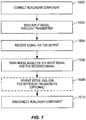
- a baseband processor sends an input signal through the transmitter (step 1002).
- the input signal is a test signal.
- the test signal may consist of a continuous wave tone, two or more continuous wave tones at different frequencies, a modulated carrier, or two or more modulated carriers at different frequencies.
- the type of test signal will depend on the algorithm that is employed to train the 3-box model.
- an amplitude of the continuous wave tone(s) may be varied to build a complete Amplitude Modulation to Amplitude Modulation (AM-AM) curve and a complete AM to Phase Modulation (AM-PM) curve if, for example, training is based on the Poza-Sarkozy-Berger (PSB) model.
- the input signal sent through the transmitter is a transmit signal that is to be transmitted by the transmitter during normal operation.
- the baseband processor then receives a signal via the TOR in response to sending the signal through the transmitter (step 1004).
- the signal received via the TOR may be, for example, an error signal representing a difference between a TOR output signal output by the TOR and an adjusted version of the signal input to the transmitter after passing through the 3-box model, as discussed above.
- the received signal may be at the same frequency as the signal sent through the transmitter (i.e., the fundamental frequency) or at the frequency of a harmonic or an intermodulation component.
- the baseband processor trains the 3-box model based on the input signal and the received signal output by the TOR (step 1006).
- the 3-box model is trained based on measuring the AM-AM and AM-PM curves of the combined transmitter-nonlinear component-TOR chain and then determining the horizontal and vertical shifts of the curves relative to one another at different frequencies.
- This technique is based on the fundamental assumption of the PSB model and can be used to extract the magnitude frequency response of the transmitter and the magnitude and phase frequency response of the TOR.
- steps 1002 through 1006 are repeated for different frequencies (step 1008).
- multiple test signals may be used such that the models of the frequency response of the transmitter and the frequency response of the TOR adequately represent the transmitter and the TOR over a desired frequency range.
Landscapes
- Engineering & Computer Science (AREA)
- Computer Networks & Wireless Communication (AREA)
- Signal Processing (AREA)
- Physics & Mathematics (AREA)
- Nonlinear Science (AREA)
- Power Engineering (AREA)
- Transmitters (AREA)
- Train Traffic Observation, Control, And Security (AREA)
Description
- The present disclosure relates to modeling a frequency response of a transmitter and/or a frequency response of a transmit observation receiver coupled to an output of the transmitter and utilizing the model(s) to improve performance of the transmitter.
-
Figure 1 illustrates aconventional system 10 that that includes atransmitter 12 and a transmit observation receiver (TOR) 14 coupled to an output of thetransmitter 12 via acoupler 16. As illustrated, thetransmitter 12 includes a digital predistorter (DPD) 18, a Digital-to-Analog Converter (DAC) 20, anupconversion subsystem 22, and a power amplifier (PA) 24 connected as shown. An output of the transmitter 12 (i.e., an output of the PA 24) is coupled to anantenna 26 via a transmit (TX)filter 28. The output of thePA 24 is also coupled to an input of theTOR 14 via thecoupler 16. The TOR 14 includes adownconversion subsystem 30 and an Analog-to-Digital Converter (ADC) 32 connected as shown. An output of theTOR 14 is coupled to a first input of asubtractor 34. The input of thetransmitter 12 is coupled to an input of a delay andgain adjustment component 36, and an output of the delay andgain adjustment component 36 is coupled to a second input of thesubtractor 34. - In operation, a
baseband processor 38 sends a digital transmit signal to the input of thetransmitter 12. The digital transmit signal is predistorted by theDPD 18 to compensate for nonlinearity of thePA 24, converted from digital to analog by theDAC 20, upconverted to a desired radio frequency by theupconversion subsystem 22, and amplified by thePA 24 to provide a radio frequency transmit signal at the output of thetransmitter 12. The radio frequency transmit signal is filtered by thetransmit filter 28, and the resulting filtered radio frequency transmit signal is transmitted via theantenna 26. TheTOR 14 samples the radio frequency transmit signal output by thetransmitter 12 to provide a digital TOR output signal at the output of theTOR 14. Thesubtractor 34 then subtracts a gain and delay adjusted version of the digital transmit signal input to thetransmitter 12 from the digital TOR output signal to provide an error signal that represents a residual InterModulation Distortion (IMD) in the radio frequency transmit signal output by thetransmitter 12. The error signal can then be utilized by thebaseband processor 38 to, for example, adaptively configure theDPD 18 to compensate for the nonlinearity of thePA 24. - The delay and
gain adjustment component 36 can accurately model a path between the input of thetransmitter 12 and the output of theTOR 14 for conventional transmit signals. However, for modern and future wireless communications standards, the transmit signals have or will have significantly wider bandwidths. For wideband transmit signals, the delay andgain adjustment component 36 is not capable of accurately modeling the path between the input of thetransmitter 12 and the output of theTOR 14. In particular, the delay andgain adjustment component 36 is not capable of accurately modeling a path between the output of thetransmitter 12 and the output of theTOR 14 for wideband transmit signals. More specifically, a frequency response of theTOR 14 varies significantly over the bandwidth of the wideband transmit signals. As a result, if only the delay andgain adjustment component 36 is used to model the path between the input of thetransmitter 12 and the output of theTOR 14 for wideband transmit signals, the performance of thetransmitter 12 will suffer (e.g., thebaseband processor 38 will take longer to adapt the DPD 18). As such, there is a need for a model of the frequency response of theTOR 14 for wideband transmit signals. - Document
WO 2013/093859 A1 (having a patent family memberUS 2013/165060 A1 ) constitutes prior art under Article 54(3) EPC and may be construed to disclose systems and methods for compensating for a non-linear characteristic of a non-linear filter in a transmit chain of a transmitter using predistortion. A transmitter includes a power amplifier configured to amplify a radio frequency input signal to provide an amplified radio frequency signal, a non-linear filter configured to filter the amplified radio frequency signal to provide an output signal of the transmitter, and a predistorter configured effect predistortion of the amplified radio frequency signal, where the predistortion compensates for a non-linear characteristic of the non-linear filter. In this manner, the output signal is as if the non-linear filter were a linear, or substantially liner, filter. The predistortion applied by the predistorter may be fixed or adaptive. - According to the disclosure, there are provided an apparatus and a method according to the independent claims. Developments are set forth in the dependent claims.
- Systems and methods for training, or calibrating, a model of a frequency response of a transmitter and/or a model of a frequency response of a transmit observation receiver (TOR) coupled to an output of the transmitter are disclosed. In one embodiment, in order to train a model of the frequency response of the transmitter and/or a model of the frequency response of the TOR, a nonlinear component is connected between an output of the transmitter and an input of the TOR. A combined model for the frequency response of the transmitter, a nonlinear characteristic of the nonlinear component, and the frequency response of the TOR is then trained. The combined model is a concatenation of a first linear filter (H1(z)) that is a model of the frequency response of the transmitter, a quasi-memoryless nonlinearity (f(·)) that is a model of the nonlinear characteristic of the nonlinear component, and a second linear filter (H2(z)) that is a model of the frequency response of the TOR. The combined model is a three-box model known as a Wiener-Hammerstein model. Preferably, once the combined model is trained, the nonlinear component is disconnected
for normal operation of the transmitter and the TOR. - In addition, systems and methods for utilizing a model of a frequency response of a transmitter and/or a model of a frequency response of a TOR coupled to an output of the transmitter to improve a performance of the transmitter are disclosed. In one embodiment, an inverse of the model of the frequency response of the TOR is applied to an output signal of the TOR during normal operation. In another embodiment, an inverse of the model of the frequency response of the transmitter is applied to an input signal of the transmitter during normal operation.
- Those skilled in the art will appreciate the scope of the present disclosure and realize additional aspects thereof after reading the following detailed description of the preferred embodiments in association with the accompanying drawing figures.
- The accompanying drawing figures incorporated in and forming a part of this specification illustrate several aspects of the disclosure, and together with the description serve to explain the principles of the disclosure.
-
Figure 1 illustrates a system that includes a conventional transmitter and transmit observation receiver (TOR); -
Figure 2 illustrates a system that includes a transmitter, a TOR, and a TOR inverse model component that compensates for a varying frequency response of the TOR over a desired observation bandwidth according to one embodiment of the present disclosure; -
Figure 3 illustrates a system that includes a transmitter, a TOR, and a transmitter inverse model component that compensates for a varying frequency response of the transmitter over a desired bandwidth according to one embodiment of the present disclosure; -
Figure 4 illustrates a system similar to that ofFigure 2 orFigure 3 in which a nonlinear component is connected between an output of the transmitter and an input of the TOR, where the system is configured to train a model of a frequency response of the transmitter and/or a model of a frequency response of the TOR according to one embodiment of the present disclosure; -
Figure 5 illustrates a system similar to that ofFigure 2 orFigure 3 in which a nonlinear component is connected between an output of the transmitter and an input of the TOR, where the system is configured to train a model of a frequency response of the transmitter and/or a model of a frequency response of the TOR according to another embodiment of the present disclosure; -
Figure 6 illustrates a system similar to that ofFigure 2 orFigure 3 in which a nonlinear component is connected between an output of the transmitter and an input of the TOR, where the system is configured to train a model of a frequency response of the transmitter and/or a model of a frequency response of the TOR according to yet another embodiment of the present disclosure; and -
Figure 7 is a flow chart that illustrates a process for training a model of a frequency response of a transmitter and/or a model of a frequency response of a TOR coupled to an output of the transmitter according to one embodiment of the present disclosure. - The embodiments set forth below represent the necessary information to enable those skilled in the art to practice the embodiments and illustrate the best mode of practicing the embodiments. Upon reading the following description in light of the accompanying drawing figures, those skilled in the art will understand the concepts of the disclosure and will recognize applications of these concepts not particularly addressed herein. It should be understood that these concepts and applications fall within the scope of the disclosure and the accompanying claims.
- Systems and methods for training, or calibrating, a model of a frequency response of a transmitter and/or a model of a frequency response of a transmit observation receiver (TOR) coupled to an output of the transmitter are disclosed. However, before describing systems and methods for training, or calibrating, a model of a frequency response of a transmitter and/or a model of a frequency response of a TOR coupled to an output of the transmitter, two exemplary systems for utilizing the models to improve performance of a transmitter are disclosed. Note, however, that these systems for utilizing the models are only examples and are not intended to limit the scope of the present disclosure.
- In this regard,
Figure 2 illustrates asystem 40 that includes atransmitter 42 and aTOR 44 coupled to an output of thetransmitter 42 via acoupler 46, wherein a model of a frequency response of theTOR 44 is utilized to improve a performance of thetransmitter 42 according to one embodiment of the present disclosure. In particular, a TORinverse model component 48 applies an inverse of the model of a frequency response of theTOR 44 to a digital TOR output signal output by theTOR 44 to thereby frequency equalize the frequency response of theTOR 44. As a result, performance of thetransmitter 42 is substantially improved. - As illustrated, the
transmitter 42 includes a digital predistorter (DPD) 50, a Digital-to-Analog Converter (DAC) 52, anupconversion subsystem 54, and a power amplifier (PA) 56 connected as shown. An output of the transmitter 42 (i.e., an output of the PA 56) is coupled to anantenna 58 via a transmit (TX)filter 60. The output of thePA 56 is also coupled to an input of theTOR 44 via thecoupler 46. The TOR 44 includes adownconversion subsystem 62 and an Analog-to-Digital Converter (ADC) 64 connected as shown. An output of theTOR 44 is coupled to an input of the TORinverse model component 48, and an output of the TORinverse model component 48 is coupled to a first input of asubtractor 66. The input of thetransmitter 42 is coupled to an input of a delay and gainadjustment component 68, and an output of the delay and gainadjustment component 68 is coupled to a second input of thesubtractor 66. Notably, while the TORinverse model component 48 is illustrated as a separate block inFigure 2 , the TOR inverse model component 48 (and the subtractor 66 and the delay and gain adjustment component 68) may alternatively be implemented within abaseband processor 70. - In operation, the
baseband processor 70 sends a digital transmit signal to the input of thetransmitter 42. The digital transmit signal is predistorted by theDPD 50 to compensate for nonlinearity of thePA 56, converted from digital to analog by theDAC 52, upconverted to a desired radio frequency by theupconversion subsystem 54, and amplified by thePA 56 to provide a radio frequency transmit signal at the output of thetransmitter 42. The radio frequency transmit signal is filtered by the transmitfilter 60, and the resulting filtered radio frequency transmit signal is transmitted via theantenna 58. TheTOR 44 samples the radio frequency transmit signal output by thetransmitter 42 to provide a digital TOR output signal at the output of theTOR 44. More specifically, the radio frequency transmit signal obtained from the output of thePA 56 via thecoupler 46 is downconverted, preferably to baseband, by thedownconversion subsystem 62 and analog to digital converted by theADC 64 to thereby provide the digital TOR output signal at the output of theTOR 44. - The digital TOR output signal is passed through the TOR
inverse model component 48 to provide a frequency-equalized digital TOR output signal. By passing the digital TOR output signal through the TORinverse model component 48, the frequency-equalized digital TOR output signal is as if the frequency response of theTOR 44 were flat, or essentially flat, over a desired observation bandwidth. Note that a "frequency-equalized" signal, such as the frequency-equalized digital TOR output signal, refers to a signal that has passed through a channel with a flat response over the desired bandwidth. A "flat" response refers to a magnitude response and a group delay response, which are independent of frequency. In one embodiment, the desired observation bandwidth is a bandwidth of a desired transmit signal within the radio frequency transmit signal output by thetransmitter 42. However, the desired observation bandwidth is not limited thereto. - The delay and gain
adjustment component 68 applies delay and gain adjustments to the digital transmit signal to provide an adjusted digital transmit signal. Preferably, the delay and gain adjustments are configured to model a path from the input of thetransmitter 42 to the output of thetransmitter 42. Thesubtractor 66 subtracts the adjusted digital transmit signal from the frequency-equalized digital TOR output signal to provide an error signal that represents a residual InterModulation Distortion (IMD) in the radio frequency transmit signal output by thetransmitter 42. In this embodiment, the error signal is provided to thebaseband processor 70 where the error signal is utilized to adaptively configure theDPD 50 to compensate for the nonlinearity of thePA 56 by minimizing, or at least reducing, the residual IMD. -
Figure 3 illustrates asystem 72 that includes atransmitter 74 and aTOR 76 coupled to an output of thetransmitter 74 via acoupler 78, wherein a model of a frequency response of thetransmitter 74 is utilized to improve a performance of thetransmitter 74 according to one embodiment of the present disclosure. In particular, a transmitterinverse model component 80 applies an inverse of the model of a frequency response of thetransmitter 74 to a digital transmit signal input to thetransmitter 74 to thereby frequency equalize the frequency response of thetransmitter 74. As a result, performance of thetransmitter 74 is substantially improved. - As illustrated, the
transmitter 74 includes aDAC 82, anupconversion subsystem 84, and aPA 86 connected as shown. Notably, while not illustrated, thetransmitter 74 may include a DPD prior to theDAC 82. An output of the transmitter 74 (i.e., an output of the PA 86) is coupled to anantenna 88 via a transmitfilter 90. The output of thePA 86 is also coupled to an input of theTOR 76 via thecoupler 78. TheTOR 76 includes adownconversion subsystem 92 and anADC 94 connected as shown. In this embodiment, an output of theTOR 76 is coupled to an input of abaseband processor 96. - In operation, the
baseband processor 96 sends a digital transmit signal to an input of the transmitterinverse model component 80. The transmitterinverse model component 80 passes the digital transmit signal through an inverse of a model of the frequency response of thetransmitter 74 to thereby provide an adjusted digital transmit signal at an output of the transmitterinverse model component 80. By passing the adjusted digital transmit signal through thetransmitter 74, the output of thetransmitter 74 is frequency-equalized. Notably, while the transmitterinverse model component 80 is illustrated as a separate block inFigure 3 , the transmitterinverse model component 80 may alternatively be implemented within thebaseband processor 96. The adjusted digital transmit signal is converted from digital to analog by theDAC 82, upconverted to a desired radio frequency by theupconversion subsystem 84, and amplified by thePA 86 to provide a radio frequency transmit signal at the output of thetransmitter 74. The radio frequency transmit signal is filtered by the transmitfilter 90, and the resulting filtered radio frequency transmit signal is transmitted via theantenna 88. By passing the digital transmit signal through the transmitterinverse model component 80, the radio frequency transmit signal is as if the frequency response of thetransmitter 74 were flat, or essentially flat, over a desired transmit bandwidth. The desired transmit bandwidth is a bandwidth of a desired transmit signal within the radio frequency transmit signal output by thetransmitter 74. - The
TOR 76 samples the radio frequency transmit signal output by thetransmitter 74 to provide a digital TOR output signal at the output of theTOR 76. More specifically, the radio frequency transmit signal obtained from the output of thePA 86 via thecoupler 78 is downconverted, preferably to baseband, by thedownconversion subsystem 92 and analog to digital converted by theADC 94 to thereby provide the digital TOR output signal at the output of theTOR 76. Thebaseband processor 96 then utilizes the digital TOR output signal to provide a desired function. As one example, the digital TOR output signal may be used to adapt a digital predistortion subsystem of thetransmitter 74. The digital predistortion subsystem may be used to linearize the transmitter 74 (e.g., compensate for a nonlinearity of thetransmitter 74 such as, for instance, a nonlinearity of the PA 86). As another example, the digital TOR output signal may be used to measure the frequency response of thetransmitter 74. - Notably, the transmitter
inverse model component 80 ofFigure 3 may be particularly beneficial for PA architectures where thePA 86 includes multiple parallel amplifier branches (e.g., a Doherty amplifier architecture). In this case, the paths, or branches, of thePA 86 can be frequency-equalized in the digital domain using the inverse of both of their transmitter frequency responses. Equalizing these paths improves performance especially as signal bandwidth increases. - In order for the embodiment of
Figure 2 to operate, the model of the frequency response of theTOR 44 must be trained, or calibrated. Likewise, in order for the embodiment ofFigure 3 to operate, the model of the frequency response of thetransmitter 74 must be trained, or calibrated. However, conventional techniques used to measure the frequency response of a channel, or path, that starts and ends in the digital domain are incapable of isolating the frequency response of thetransmitter TOR transmitter TOR transmitter TOR transmitter transmitter TOR 44, 76). However, it is desirable to measure the frequency responses of thetransmitter TOR transmitter TOR 44, 76 (i.e., connectors to connect the radio frequency test equipment). -
Figures 4-7 illustrate systems and methods for training models of a frequency response of a transmitter and a frequency response of a TOR coupled to the output of the transmitter without the use of radio frequency test equipment according to several embodiments of the present disclosure. In this regard,Figure 4 illustrates asystem 98 including atransmitter 100 and aTOR 102 coupled to an output of thetransmitter 100 via acoupler 104 in which anonlinear component 106 is connected between the output of thetransmitter 100 and thecoupler 104 to enable training of a model of a frequency response of thetransmitter 100 and a model of a frequency response of theTOR 102 according to one embodiment of the present disclosure. In one embodiment, thesystem 98 is thesystem 40 ofFigure 2 that is configured for a training mode by connecting thenonlinear component 106 between the output of thetransmitter 42 and thecoupler 46 and decoupling or deactivating the DPD 50 (Figure 2 ). After training, thesystem 40 is reconfigured for a normal mode by disconnecting thenonlinear component 106 and re-coupling or re-activating theDPD 50. In another embodiment, thesystem 98 is thesystem 72 ofFigure 3 that is configured for a training mode by connecting thenonlinear component 106 between the output of thetransmitter 74 and the coupler 78 (Figure 3 ). After training, thesystem 72 is reconfigured for a normal mode by disconnecting thenonlinear component 106. Thenonlinear component 106 is connected and disconnected between the output of thetransmitter 100 and thecoupler 104 using any suitable technique. For example, in one embodiment, thenonlinear component 106 is connected and disconnected via one or more switches. As another example, thenonlinear component 106 is connected via soldering or similar technique and disconnected by physically removing thenonlinear component 106 or otherwise destroying the connection made via soldering. - A frequency response of the
transmitter 100, a nonlinear characteristic of thenonlinear component 106, and a frequency response of theTOR 102 are modeled by a combinedmodel 108. The combinedmodel 108 is a 3-box model that is a concatenation or cascade of a model of a first linear filter (H1(z)) 110, a model of a quasi-memoryless nonlinearity (f(·)) 112, and a model of a second linear filter (H2(z)) 114. As used herein, the term quasi-memoryless corresponds to memory with very short time constants such as, for example, reactive parts (i.e., capacitance and inductance) inherent to any real nonlinear component. Once the combinedmodel 108 is trained, the model of the first linear filter (H1(z)) 110 is a model of the frequency response of thetransmitter 100, the model of the quasi-memoryless nonlinearity (f(·)) 112 is a model of the nonlinear characteristic of thenonlinear component 106, and the model of the second linear filter (H2(z)) 114 is a model of the frequency response of theTOR 102. The 3-box model forming the combinedmodel 108 is also known as a Wiener-Hammerstein model. Techniques for determining parameters that define the 3-box model (i.e., both filter coefficients for the first and second linear filters (H1(z) and H2(z)) 110 and 114 and a nonlinearity characteristic of the quasi-memoryless nonlinearity f(·)) 112 are known. For example, while not necessary for understanding the present disclosure, one exemplary and non-limiting technique for determining the parameters of the 3-box model is described in Dominique Schreurs et al., "RF Power Amplifier Behavioral Modeling," Cambridge University Press, Cambridge, UK, 2009. Any suitable technique for determining the parameters that define the 3-box model can be used to train the combinedmodel 108 and, more particularly, the models of the first and second linear filters (H1(z) and H2(z)) 110 and 114, which correspond to the models of the frequency responses of thetransmitter 100 and theTOR 102, respectively. - In one embodiment, the
nonlinear component 106 is quasi-memoryless. However, in another embodiment, the nonlinear characteristic of thenonlinear component 106 is known and characterized prior to training in which case thenonlinear component 106 may or may not be quasi-memoryless. If the nonlinearity characteristic of thenon-linear component 106 is known and characterized prior to training, training of the combinedmodel 108 is simplified. If the nonlinearity characteristic of thenonlinear component 106 is not known prior to training, the nonlinearity characteristic of thenonlinear component 106 is also determined by training the combinedmodel 108. - As illustrated, the
transmitter 100 includes aDAC 116, anupconversion subsystem 118, and aPA 120 connected as shown. An output of the transmitter 100 (i.e., an output of the PA 120) is coupled to anantenna 122 via a transmitfilter 124. The output of thePA 120 is also coupled to an input of theTOR 102 via thecoupler 104. TheTOR 102 includes adownconversion subsystem 126 and anADC 128 connected as shown. An output of theTOR 102 is coupled to a first input of asubtractor 130. The input of thetransmitter 100 is coupled to an input of the combinedmodel 108, and an output of the combinedmodel 108 is coupled to a second input of thesubtractor 130. - In order to train the combined
model 108, abaseband processor 132 sends one or more digital test signals to the input of thetransmitter 100 during a training mode of operation. In this embodiment, the one or more test signals are small signals such that thenonlinear component 106 is a dominant source of IMD in the path from the input of thetransmitter 100 to the output of thenonlinear component 106 and the nonlinear distortion of thePA 120 is negligible. Thenonlinear component 106 is preferably quasi-memoryless and ideally has a strong nonlinearity. As used herein, a small signal is a signal that is sufficiently small to ensure that the components of thetransmitter 100, and in particular thePA 120, operate linearly when processing the signal. In addition, for wideband applications, the one or more test signals include multiple test signals at multiple different frequencies. - For each of the one or more digital test signals, the digital test signal is converted from digital to analog by the
DAC 116, upconverted to a desired radio frequency by theupconversion subsystem 118, and amplified by thePA 120 to provide a radio frequency test signal at the output of thetransmitter 100. The radio frequency test signal is passed through thenonlinear component 106 to provide a nonlinear component output signal. The nonlinear component output signal is provided to the input of theTOR 102 via thecoupler 104. TheTOR 102 samples the nonlinear component output signal output by thenonlinear component 106 to provide a digital TOR output signal at the output of theTOR 102. More specifically, the nonlinear component output signal obtained from the output of thenonlinear component 106 via thecoupler 104 is downconverted, preferably to baseband, by thedownconversion subsystem 126 and analog to digital converted by theADC 128 to thereby provide the digital TOR output signal at the output of theTOR 102. - The digital TOR output signal is provided to the first input of the
subtractor 130. The digital test signal is passed through the combinedmodel 108 to provide an adjusted digital test signal to the second input of thesubtractor 130. Thesubtractor 130 subtracts the adjusted digital test signal from the digital TOR output signal to provide an error signal. Thebaseband processor 132 processes the error signal to train the combinedmodel 108. Once the combinedmodel 108 is trained, the models of the first and second linear filters (H1(z) and H2(z)) 110 and 114 correspond to the models of the frequency responses of thetransmitter 100 and theTOR 102, respectively. It should be noted that while the combinedmodel 108 is illustrated as a separate block, the combined model 108 (and the subtractor 130) may alternatively be implemented within thebaseband processor 132. -
Figure 5 illustrates thesystem 98 ofFigure 4 according to another embodiment of the present disclosure. This embodiment is substantially the same as that ofFigure 4 but where thenonlinear component 106 is connected between thecoupler 104 and the input of theTOR 102. In the case where thenonlinear component 106 is connected and disconnected via switches, the embodiment ofFigure 5 would remove the need to place the switches in the transmitter path (i.e., the path between the input of thetransmitter 100 and the antenna 122). It should also be noted that, in this embodiment, the model of the second linear filter (H2(z)) 114 does not include the coupled port of thecoupler 104. -
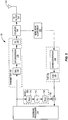
Figure 6 illustrates asystem 134 including atransmitter 136 and aTOR 138 coupled to an output of thetransmitter 136 via acoupler 140 in which anonlinear component 142 is connected between thecoupler 140 and an input of theTOR 138 to enable training of a model of a frequency response of thetransmitter 136 and a model of a frequency response of theTOR 138 according to one embodiment of the present disclosure. In this embodiment, the models of the frequency responses of thetransmitter 136 and theTOR 138 are trained during normal operation of the transmitter 136 (i.e., during transmission of normal transmit signals rather than test signals). In one embodiment, thesystem 134 is thesystem 40 ofFigure 2 that is configured for training during normal operation by connecting thenonlinear component 142 between thecoupler 46 and the input of the TOR 44 (Figure 2 ). After training, thenonlinear component 142 can be disconnected. In another embodiment, thesystem 134 is thesystem 72 ofFigure 3 that is configured for training during normal operation by connecting thenonlinear component 142 between thecoupler 78 and the input of the TOR 76 (Figure 3 ). After training, thenonlinear component 142 can be disconnected. Thenonlinear component 142 is connected and disconnected between thecoupler 140 and the input of theTOR 138 using any suitable technique. For example, in one embodiment, thenonlinear component 142 is connected and disconnected via one or more switches. As another example, thenonlinear component 142 is connected via soldering or similar technique and disconnected by physically removing thenonlinear component 142 or otherwise destroying the connection made via soldering. - A frequency response of the
transmitter 136, a nonlinear characteristic of thenonlinear component 142, and a frequency response of theTOR 138 are modeled by a combinedmodel 144. Again, the combinedmodel 144 is a 3-box model that is a concatenation or cascade of a model of a first linear filter (H1(z)) 146, a model of a quasi-memoryless nonlinearity (f(·)) 148, and a model of a second linear filter (H2(z)) 150. Once the combinedmodel 144 is trained, the model of the first linear filter (H1(z)) 146 is a model of the frequency response of thetransmitter 136, the model of the quasi-memoryless nonlinearity (f(·)) 148 is a model of the nonlinear characteristic of thenonlinear component 142, and the model of the second linear filter (H2(z)) 150 is a model of the frequency response of theTOR 138. The 3-box model forming the combinedmodel 144 is also known as a Wiener-Hammerstein model. Techniques for determining parameters that define the 3-box model (i.e., both filter coefficients for the first and second linear filters (H1(z) and H2(z)) 146 and 150 and the nonlinear characteristic of the quasi-memoryless nonlinearity f(·)) 148 are known. For example, while not necessary for understanding the present disclosure, one exemplary and non-limiting technique for determining the parameters of the 3-box model is described in Dominique Schreurs et al., "RF Power Amplifier Behavioral Modeling," Cambridge University Press, Cambridge, UK, 2009. Any suitable technique for determining the parameters that define the 3-box model can be used to train the combinedmodel 144 and, more particularly, the models of the first and second linear filters (H1(z) and H2(z)) 146 and 150, which correspond to the models of the frequency responses of thetransmitter 136 and theTOR 138, respectively. - In one embodiment, the
nonlinear component 142 is quasi-memoryless. However, in another embodiment, the nonlinear characteristic of thenonlinear component 142 is known and characterized prior to training in which case thenonlinear component 142 may or may not be quasi-memoryless. If the nonlinearity characteristic of thenon-linear component 142 is known and characterized prior to training, training of the combinedmodel 144 is simplified. If the nonlinearity characteristic of thenonlinear component 142 is not known prior to training, the nonlinearity characteristic of thenonlinear component 142 is also determined by training the combinedmodel 144. - As illustrated, the
transmitter 136 includes aDPD 152, aDAC 154, anupconversion subsystem 156, and aPA 158 connected as shown. An output of the transmitter 136 (i.e., an output of the PA 158) is coupled to anantenna 160 via a transmitfilter 162. The output of thePA 158 is also coupled to an input of thenonlinear component 142 via thecoupler 140, and an output of thenonlinear component 142 is coupled to the input of theTOR 138. TheTOR 138 includes adownconversion subsystem 164 and anADC 166 connected as shown. An output of theTOR 138 is coupled to a first input of asubtractor 168. The input of thetransmitter 136 is coupled to an input of the combinedmodel 144, and an output of the combinedmodel 144 is coupled to a second input of thesubtractor 168. - In order to train the combined
model 144, abaseband processor 170 sends one or more digital transmit signals to the input of thetransmitter 136 during normal operation. Notably, a linearization scheme of thetransmitter 136, which in this embodiment is theDPD 152, is operational. Also note that, in this embodiment, thenonlinear component 142 cannot be placed in the transmit path as it would cause thetransmitter 136 to exhibit strong nonlinear behavior. The digital transmit signal is predistorted by theDPD 152 to compensate for the nonlinearity of thePA 158, converted from digital to analog by theDAC 154, upconverted to a desired radio frequency by theupconversion subsystem 156, and amplified by thePA 158 to provide a radio frequency transmit signal at the output of thetransmitter 136. The radio frequency transmit signal is passed to theantenna 160 via the transmitfilter 162. - In addition, the radio frequency transmit signal is provided to the input of the
nonlinear component 142 via thecoupler 140. The radio frequency transmit signal is passed through thenonlinear component 142 to provide a nonlinear component output signal. TheTOR 138 samples the nonlinear component output signal output by thenonlinear component 142 to provide a digital TOR output signal at the output of theTOR 138. More specifically, the nonlinear component output signal obtained from the output of thenonlinear component 142 is downconverted, preferably to baseband, by thedownconversion subsystem 164 and analog to digital converted by theADC 166 to thereby provide the digital TOR output signal at the output of theTOR 138. - The digital TOR output signal is provided to the first input of the
subtractor 168. The digital transmit signal input to thetransmitter 136 is also passed through the combinedmodel 144 to provide an adjusted digital transmit signal to the second input of thesubtractor 168. Thesubtractor 168 subtracts the adjusted digital transmit signal from the digital TOR output signal to provide an error signal. Thebaseband processor 170 processes the error signal to train the combinedmodel 144. Once the combinedmodel 144 is trained, the models of the first and second linear filters (H1(z) and H2(z)) 146 and 150 correspond to the models of the frequency responses of thetransmitter 136 and theTOR 138, respectively. It should be noted that while the combinedmodel 144 is illustrated as a separate block, the combined model 144 (and the subtractor 168) may alternatively be implemented within thebaseband processor 170. -
Figure 7 illustrates a process for training a model of a frequency response of a transmitter and a model of a frequency response of a TOR coupled to an output of the transmitter according to one embodiment of the present disclosure. First, a nonlinear component is connected between an output of the transmitter and an input of the TOR (step 1000). As discussed above, the nonlinear component may be connected between the output of the transmitter and a coupler that couples the output of the transmitter to the input of the TOR or connected between the coupler and the input of the TOR. Further, the nonlinear component may be connected using any suitable technique such as, for example, switches or soldering. The nonlinear component is preferably quasi-memoryless, but may alternatively not be quasi-memoryless if a nonlinearity characteristic of the nonlinear component is known and adequately characterized before training. - By connecting the nonlinear component between the output of the transmitter and the input of the TOR, a 3-box model can be used to model the frequency response of the transmitter, a nonlinear characteristic of the nonlinear component, and the frequency response of the TOR. More specifically, as discussed above, the 3-box model, which is also known as the Wiener-Hammerstein model, consists of concatenation or cascade of a model of a first linear filter (H1(z)), a model of a quasi-memoryless nonlinearity (f(·)), and a model of a second linear filter (H2(z)). After training, the model of the first linear filter (H1(z)) is the model of the frequency response of the transmitter, and the model of the second linear filter (H2(z)) is the model of the frequency response of the TOR.
- Once the nonlinear component is connected, a baseband processor sends an input signal through the transmitter (step 1002). In one embodiment, the input signal is a test signal. The test signal may consist of a continuous wave tone, two or more continuous wave tones at different frequencies, a modulated carrier, or two or more modulated carriers at different frequencies. The type of test signal will depend on the algorithm that is employed to train the 3-box model. Notably, for continuous wave tone(s), an amplitude of the continuous wave tone(s) may be varied to build a complete Amplitude Modulation to Amplitude Modulation (AM-AM) curve and a complete AM to Phase Modulation (AM-PM) curve if, for example, training is based on the Poza-Sarkozy-Berger (PSB) model. In another embodiment, the input signal sent through the transmitter is a transmit signal that is to be transmitted by the transmitter during normal operation.
- The baseband processor then receives a signal via the TOR in response to sending the signal through the transmitter (step 1004). The signal received via the TOR may be, for example, an error signal representing a difference between a TOR output signal output by the TOR and an adjusted version of the signal input to the transmitter after passing through the 3-box model, as discussed above. The received signal may be at the same frequency as the signal sent through the transmitter (i.e., the fundamental frequency) or at the frequency of a harmonic or an intermodulation component. The baseband processor trains the 3-box model based on the input signal and the received signal output by the TOR (step 1006). While any suitable technique or algorithm for training the 3-box model can be used, in one particular embodiment, the 3-box model is trained based on measuring the AM-AM and AM-PM curves of the combined transmitter-nonlinear component-TOR chain and then determining the horizontal and vertical shifts of the curves relative to one another at different frequencies. This technique is based on the fundamental assumption of the PSB model and can be used to extract the magnitude frequency response of the transmitter and the magnitude and phase frequency response of the TOR.
- In some embodiments,
steps 1002 through 1006 are repeated for different frequencies (step 1008). In particular, in the case of continuous wave tones or narrowband modulated carriers, multiple test signals may be used such that the models of the frequency response of the transmitter and the frequency response of the TOR adequately represent the transmitter and the TOR over a desired frequency range. Once training is complete, the nonlinear component is disconnected (step 1010). - The following acronyms are used throughout this disclosure.
- ADC Analog-to-Digital Converter
- AM-AM Amplitude Modulation to Amplitude Modulation
- AM-PM Amplitude Modulation to Phase Modulation
- DAC Digital-to-Analog Converter
- DPD Digital Predistorter
- IMD InterModulation Distortion
- PA Power Amplifier
- PSB Poza-Sarkozy-Berger
- TOR Transmit Observation Receiver
- TX Transmit
- Those skilled in the art will recognize improvements and modifications to the preferred embodiments of the present disclosure. All such improvements and modifications are considered within the scope of the claims that follow.
Claims (16)
- A method comprising:connecting (1000) a nonlinear component (106, 142) between an output of a transmitter (74, 100, 136) and an input of a transmit observation receiver, TOR, (76, 102, 138) that is coupled to the output of the transmitter;training (1002, 1004, 1006) a combined model (108, 144) of a frequency response of the transmitter, a nonlinear characteristic of the nonlinear component, and a frequency response of the TOR using a signal generated from an input signal to the transmitter and an output signal of the TOR, the combined model comprising concatenation of a model of a first linear filter (110, 146) that corresponds to a model of the frequency response of the transmitter, a model of a quasi-memoryless nonlinearity (112, 148) that represents a model of the nonlinear characteristic of the nonlinear component, and a model of a second linear filter (114, 150) that represents a model of the frequency response of the TOR; anddisconnecting (1010) the nonlinear component after training the combined model.
- The method of claim 1 wherein connecting the nonlinear component comprises connecting the nonlinear component between the output of the transmitter and a coupler (78, 104, 140) that couples the output of the transmitter to the input of the TOR; or
wherein connecting the nonlinear component comprises connecting the non-linear component between a coupler (78, 104, 140) that couples the output of the transmitter to the input of the TOR and the input of the TOR. - The method of any of the preceding claims wherein training the combined model of the frequency response of the transmitter, the nonlinear characteristic of the nonlinear component, and the frequency response of the TOR comprises:providing (1002) one or more test signals to an input of the transmitter;receiving (1004) one or more observed test signals from an output of the TOR in response to providing the one or more test signals to the input of the transmitter; andtraining (1006) the combined model based on the one or more test signals and the one or more observed test signals.
- The method of claim 3 wherein the one or more test signals are small signals such that components of the transmitter operate linearly, and, optionally, wherein the one or more test signals comprise a plurality of test signals at different frequencies (1008).
- The method of any of the preceding claims wherein the transmitter comprises a digital predistortion subsystem (152), and training the combined model of the frequency response of the transmitter, the nonlinear characteristic of the nonlinear component, and the frequency response of the TOR comprises training the combined model during normal operation while the digital predistortion subsystem is active.
- The method of claim 5 wherein connecting the nonlinear component comprises connecting the nonlinear component between a coupler (78, 104, 140) that couples the output of the transmitter to the input of the TOR and the input of the TOR.
- The method of any of the preceding claims further comprising, after training the combined model:applying an inverse (80) of the model of the frequency response of the TOR to an output signal of the TOR during normal operation, orapplying an inverse (80) of the model of the frequency response of the transmitter to an input signal of the transmitter during normal operation.
- The method of any of the preceding claims wherein the nonlinear component has a known nonlinear characteristic, and training the combined model comprises training the combined model based on the known nonlinear characteristic of the nonlinear component.
- The method of any of the preceding claims wherein the nonlinear component is a quasi-memoryless nonlinear component.
- A system (72, 98, 134) comprising:a transmitter (74, 100, 136);a transmit observation receiver, TOR, (76, 102, 138) having an input that is coupled to an output of the transmitter;a nonlinear component (106, 142) connected between the output of the transmitter and the input of the TOR; anda baseband processor (96, 132, 170) configured to train a combined model (108, 144) of a frequency response of the transmitter, a nonlinear characteristic of the nonlinear component, and a frequency response of the TOR using a signal generated from an input signal to the transmitter and an output signal of the TOR, the combined model comprising concatenation of a model of a first linear filter (110, 146) that corresponds to a model of the frequency response of the transmitter, a model of a quasi-memoryless nonlinearity (112, 148) that represents a model of the nonlinear characteristic of the nonlinear component, and a model of a second linear filter (114, 150) that represents a model of the frequency response of the TOR,wherein the nonlinear component is disconnected after the combined model is trained.
- The system of claim 10 wherein the nonlinear component is connected between the output of the transmitter and a coupler (78, 104, 140) configured to couple the output of the transmitter to the input of the TOR; or
wherein the nonlinear component is connected between a coupler (78, 104, 140) configured to couple the output of the transmitter to the input of the TOR and the input of the TOR. - The system of claim 10 or 11 wherein, in order to train the combined model, the baseband processor is further configured to:- provide one or more test signals to an input of the transmitter;- receive one or more observed test signals from an output of the TOR in response to providing the one or more test signals to the input of the transmitter; and- train the combined model based on the one or more test signals and the one or more observed test signals.
- The system of claim 12 wherein the one or more test signals are small signals such that components of the transmitter operate linearly, wherein, optionally the one or more test signals comprise a plurality of test signals at different frequencies.
- The system of any of claims 10 to 13 wherein the transmitter comprises a digital predistortion subsystem (152), and the baseband processor (170) is configured to train the combined model during normal operation while the digital predistortion subsystem is active.
- The system of claim 14 wherein the nonlinear component is connected between a coupler (78, 104, 140) configured to couple the output of the transmitter to the input of the TOR and the input of the TOR.
- The system of any of claims 9 to 15 wherein, after the combined model is trained, an inverse model component (80) is configured to apply an inverse of the model of the frequency response of the TOR to an output signal of the TOR during normal operation; or
wherein, after the combined model is trained, the nonlinear component is disconnected, and an inverse model component (80) is configured to apply an inverse of the model of the frequency response of the transmitter to an input signal of the transmitter during normal operation.
Applications Claiming Priority (1)
| Application Number | Priority Date | Filing Date | Title |
|---|---|---|---|
| US13/734,238 US9036732B2 (en) | 2013-01-04 | 2013-01-04 | Modeling transmitter and/or transmit observation receiver frequency response and utilization thereof |
Publications (3)
| Publication Number | Publication Date |
|---|---|
| EP2752995A2 EP2752995A2 (en) | 2014-07-09 |
| EP2752995A3 EP2752995A3 (en) | 2017-08-02 |
| EP2752995B1 true EP2752995B1 (en) | 2018-04-11 |
Family
ID=49765258
Family Applications (1)
| Application Number | Title | Priority Date | Filing Date |
|---|---|---|---|
| EP13005700.3A Active EP2752995B1 (en) | 2013-01-04 | 2013-12-06 | Modeling transmitter and/or transmit observation receiver frequency response and utilization thereof |
Country Status (2)
| Country | Link |
|---|---|
| US (1) | US9036732B2 (en) |
| EP (1) | EP2752995B1 (en) |
Families Citing this family (4)
| Publication number | Priority date | Publication date | Assignee | Title |
|---|---|---|---|---|
| US10243678B2 (en) * | 2013-10-28 | 2019-03-26 | National Instruments Corporation | Linearization of radio frequency transceivers and test systems through dynamic extraction of complex nonlinear models thereof |
| WO2020169196A1 (en) | 2019-02-20 | 2020-08-27 | Telefonaktiebolaget Lm Ericsson (Publ) | Blind distortion compensation for wireless systems |
| CN115298978B (en) * | 2020-03-18 | 2023-10-27 | 哲库科技(上海)有限公司 | Baseband chip for harmonic interference cancellation and wireless communication method |
| TWI779779B (en) * | 2021-08-18 | 2022-10-01 | 瑞昱半導體股份有限公司 | Transceiver and transceiver calibration method |
Family Cites Families (3)
| Publication number | Priority date | Publication date | Assignee | Title |
|---|---|---|---|---|
| US7149482B2 (en) * | 2003-09-16 | 2006-12-12 | Andrew Corporation | Compensation of filters in radio transmitters |
| WO2011069275A1 (en) * | 2009-12-09 | 2011-06-16 | Telefonaktiebolaget L M Ericsson (Publ) | A method and device for compensating frequency response of a filter unit in remote radio unit in real time |
| US9374044B2 (en) * | 2011-12-21 | 2016-06-21 | Telefonaktiebolaget L M Ericsson (Publ) | Architecture of nonlinear RF filter-based transmitter |
-
2013
- 2013-01-04 US US13/734,238 patent/US9036732B2/en active Active
- 2013-12-06 EP EP13005700.3A patent/EP2752995B1/en active Active
Non-Patent Citations (1)
| Title |
|---|
| None * |
Also Published As
| Publication number | Publication date |
|---|---|
| US20140192922A1 (en) | 2014-07-10 |
| EP2752995A3 (en) | 2017-08-02 |
| US9036732B2 (en) | 2015-05-19 |
| EP2752995A2 (en) | 2014-07-09 |
Similar Documents
| Publication | Publication Date | Title |
|---|---|---|
| US8855175B2 (en) | Low complexity all-digital PIM compensator | |
| US9374044B2 (en) | Architecture of nonlinear RF filter-based transmitter | |
| CN101175061B (en) | Self-adapting digital predistortion method and apparatus for OFDM transmitter | |
| US8489043B2 (en) | Distortion compensation apparatus and apparatus and method for transmitting signal | |
| US8824980B2 (en) | System and method to implement a radio transmitter with digital predistortion having reduced noise | |
| US8428525B2 (en) | Predistorter for a multi-antenna transmitter | |
| EP2795792B1 (en) | Adaptive predistortion for a non-linear subsystem based on a model as a concatenation of a non-linear model followed by a linear model | |
| US20170257251A1 (en) | Predistortion Processing Apparatus and Method | |
| WO2008116402A1 (en) | The predistortion apparatus, transmitter and the method | |
| US9124225B2 (en) | Dual power amplifier linearizer | |
| EP2752995B1 (en) | Modeling transmitter and/or transmit observation receiver frequency response and utilization thereof | |
| WO2008110396A1 (en) | Predistortion with asymmetric usage of available bandwidth | |
| US8811532B2 (en) | Architecture and the training method of a PA DPD system with space mapping applied in the predistorter | |
| Tripathi et al. | Swish activation based deep neural network predistorter for RF-PA | |
| KR101386239B1 (en) | Predistorter for compensating of nonlinear distortion and method for the same | |
| CN109428610B (en) | Feedback circuit unit, ROF wireless transmitter and method for eliminating nonlinear distortion | |
| CN111064439A (en) | System and method for improving short-wave digital predistortion performance | |
| Anttila et al. | Recursive learning-based joint digital predistorter for power amplifier and I/Q modulator impairments | |
| EP2795802B1 (en) | Architecture of a low bandwidth predistortion system for non-linear rf components | |
| JPWO2016021178A1 (en) | Transmitter, transmission system, and transmission method | |
| Wang et al. | Research of adaptive digital predistortion technology for wideband OFDM power amplifier | |
| KR100913224B1 (en) | Radio frequency repeater | |
| KR20090097396A (en) | Method for linearizing digital predistortion of power amplifier | |
| KR20130063653A (en) | Digital predistortion compensation apparatus for preventing divergence of amplifier output and method using the same |
Legal Events
| Date | Code | Title | Description |
|---|---|---|---|
| 17P | Request for examination filed |
Effective date: 20131206 |
|
| AK | Designated contracting states |
Kind code of ref document: A2 Designated state(s): AL AT BE BG CH CY CZ DE DK EE ES FI FR GB GR HR HU IE IS IT LI LT LU LV MC MK MT NL NO PL PT RO RS SE SI SK SM TR |
|
| AX | Request for extension of the european patent |
Extension state: BA ME |
|
| PUAI | Public reference made under article 153(3) epc to a published international application that has entered the european phase |
Free format text: ORIGINAL CODE: 0009012 |
|
| PUAL | Search report despatched |
Free format text: ORIGINAL CODE: 0009013 |
|
| AK | Designated contracting states |
Kind code of ref document: A3 Designated state(s): AL AT BE BG CH CY CZ DE DK EE ES FI FR GB GR HR HU IE IS IT LI LT LU LV MC MK MT NL NO PL PT RO RS SE SI SK SM TR |
|
| AX | Request for extension of the european patent |
Extension state: BA ME |
|
| RIC1 | Information provided on ipc code assigned before grant |
Ipc: H04B 1/04 20060101AFI20170629BHEP Ipc: H04B 1/40 20150101ALI20170629BHEP |
|
| STAA | Information on the status of an ep patent application or granted ep patent |
Free format text: STATUS: REQUEST FOR EXAMINATION WAS MADE |
|
| GRAP | Despatch of communication of intention to grant a patent |
Free format text: ORIGINAL CODE: EPIDOSNIGR1 |
|
| STAA | Information on the status of an ep patent application or granted ep patent |
Free format text: STATUS: GRANT OF PATENT IS INTENDED |
|
| R17P | Request for examination filed (corrected) |
Effective date: 20171116 |
|
| RBV | Designated contracting states (corrected) |
Designated state(s): AL AT BE BG CH CY CZ DE DK EE ES FI FR GB GR HR HU IE IS IT LI LT LU LV MC MK MT NL NO PL PT RO RS SE SI SK SM TR |
|
| INTG | Intention to grant announced |
Effective date: 20171222 |
|
| GRAS | Grant fee paid |
Free format text: ORIGINAL CODE: EPIDOSNIGR3 |
|
| GRAA | (expected) grant |
Free format text: ORIGINAL CODE: 0009210 |
|
| STAA | Information on the status of an ep patent application or granted ep patent |
Free format text: STATUS: THE PATENT HAS BEEN GRANTED |
|
| AK | Designated contracting states |
Kind code of ref document: B1 Designated state(s): AL AT BE BG CH CY CZ DE DK EE ES FI FR GB GR HR HU IE IS IT LI LT LU LV MC MK MT NL NO PL PT RO RS SE SI SK SM TR |
|
| REG | Reference to a national code |
Ref country code: GB Ref legal event code: FG4D |
|
| REG | Reference to a national code |
Ref country code: CH Ref legal event code: EP |
|
| REG | Reference to a national code |
Ref country code: AT Ref legal event code: REF Ref document number: 989062 Country of ref document: AT Kind code of ref document: T Effective date: 20180415 |
|
| REG | Reference to a national code |
Ref country code: IE Ref legal event code: FG4D |
|
| REG | Reference to a national code |
Ref country code: DE Ref legal event code: R096 Ref document number: 602013035604 Country of ref document: DE |
|
| REG | Reference to a national code |
Ref country code: NL Ref legal event code: MP Effective date: 20180411 |
|
| REG | Reference to a national code |
Ref country code: LT Ref legal event code: MG4D |
|
| PG25 | Lapsed in a contracting state [announced via postgrant information from national office to epo] |
Ref country code: NL Free format text: LAPSE BECAUSE OF FAILURE TO SUBMIT A TRANSLATION OF THE DESCRIPTION OR TO PAY THE FEE WITHIN THE PRESCRIBED TIME-LIMIT Effective date: 20180411 |
|
| PG25 | Lapsed in a contracting state [announced via postgrant information from national office to epo] |
Ref country code: FI Free format text: LAPSE BECAUSE OF FAILURE TO SUBMIT A TRANSLATION OF THE DESCRIPTION OR TO PAY THE FEE WITHIN THE PRESCRIBED TIME-LIMIT Effective date: 20180411 Ref country code: NO Free format text: LAPSE BECAUSE OF FAILURE TO SUBMIT A TRANSLATION OF THE DESCRIPTION OR TO PAY THE FEE WITHIN THE PRESCRIBED TIME-LIMIT Effective date: 20180711 Ref country code: LT Free format text: LAPSE BECAUSE OF FAILURE TO SUBMIT A TRANSLATION OF THE DESCRIPTION OR TO PAY THE FEE WITHIN THE PRESCRIBED TIME-LIMIT Effective date: 20180411 Ref country code: PL Free format text: LAPSE BECAUSE OF FAILURE TO SUBMIT A TRANSLATION OF THE DESCRIPTION OR TO PAY THE FEE WITHIN THE PRESCRIBED TIME-LIMIT Effective date: 20180411 Ref country code: ES Free format text: LAPSE BECAUSE OF FAILURE TO SUBMIT A TRANSLATION OF THE DESCRIPTION OR TO PAY THE FEE WITHIN THE PRESCRIBED TIME-LIMIT Effective date: 20180411 Ref country code: AL Free format text: LAPSE BECAUSE OF FAILURE TO SUBMIT A TRANSLATION OF THE DESCRIPTION OR TO PAY THE FEE WITHIN THE PRESCRIBED TIME-LIMIT Effective date: 20180411 Ref country code: SE Free format text: LAPSE BECAUSE OF FAILURE TO SUBMIT A TRANSLATION OF THE DESCRIPTION OR TO PAY THE FEE WITHIN THE PRESCRIBED TIME-LIMIT Effective date: 20180411 Ref country code: BG Free format text: LAPSE BECAUSE OF FAILURE TO SUBMIT A TRANSLATION OF THE DESCRIPTION OR TO PAY THE FEE WITHIN THE PRESCRIBED TIME-LIMIT Effective date: 20180711 |
|
| PG25 | Lapsed in a contracting state [announced via postgrant information from national office to epo] |
Ref country code: LV Free format text: LAPSE BECAUSE OF FAILURE TO SUBMIT A TRANSLATION OF THE DESCRIPTION OR TO PAY THE FEE WITHIN THE PRESCRIBED TIME-LIMIT Effective date: 20180411 Ref country code: RS Free format text: LAPSE BECAUSE OF FAILURE TO SUBMIT A TRANSLATION OF THE DESCRIPTION OR TO PAY THE FEE WITHIN THE PRESCRIBED TIME-LIMIT Effective date: 20180411 Ref country code: GR Free format text: LAPSE BECAUSE OF FAILURE TO SUBMIT A TRANSLATION OF THE DESCRIPTION OR TO PAY THE FEE WITHIN THE PRESCRIBED TIME-LIMIT Effective date: 20180712 Ref country code: HR Free format text: LAPSE BECAUSE OF FAILURE TO SUBMIT A TRANSLATION OF THE DESCRIPTION OR TO PAY THE FEE WITHIN THE PRESCRIBED TIME-LIMIT Effective date: 20180411 |
|
| REG | Reference to a national code |
Ref country code: AT Ref legal event code: MK05 Ref document number: 989062 Country of ref document: AT Kind code of ref document: T Effective date: 20180411 |
|
| PG25 | Lapsed in a contracting state [announced via postgrant information from national office to epo] |
Ref country code: PT Free format text: LAPSE BECAUSE OF FAILURE TO SUBMIT A TRANSLATION OF THE DESCRIPTION OR TO PAY THE FEE WITHIN THE PRESCRIBED TIME-LIMIT Effective date: 20180813 |
|
| REG | Reference to a national code |
Ref country code: DE Ref legal event code: R097 Ref document number: 602013035604 Country of ref document: DE |
|
| PG25 | Lapsed in a contracting state [announced via postgrant information from national office to epo] |
Ref country code: EE Free format text: LAPSE BECAUSE OF FAILURE TO SUBMIT A TRANSLATION OF THE DESCRIPTION OR TO PAY THE FEE WITHIN THE PRESCRIBED TIME-LIMIT Effective date: 20180411 Ref country code: DK Free format text: LAPSE BECAUSE OF FAILURE TO SUBMIT A TRANSLATION OF THE DESCRIPTION OR TO PAY THE FEE WITHIN THE PRESCRIBED TIME-LIMIT Effective date: 20180411 Ref country code: AT Free format text: LAPSE BECAUSE OF FAILURE TO SUBMIT A TRANSLATION OF THE DESCRIPTION OR TO PAY THE FEE WITHIN THE PRESCRIBED TIME-LIMIT Effective date: 20180411 Ref country code: SK Free format text: LAPSE BECAUSE OF FAILURE TO SUBMIT A TRANSLATION OF THE DESCRIPTION OR TO PAY THE FEE WITHIN THE PRESCRIBED TIME-LIMIT Effective date: 20180411 Ref country code: CZ Free format text: LAPSE BECAUSE OF FAILURE TO SUBMIT A TRANSLATION OF THE DESCRIPTION OR TO PAY THE FEE WITHIN THE PRESCRIBED TIME-LIMIT Effective date: 20180411 Ref country code: RO Free format text: LAPSE BECAUSE OF FAILURE TO SUBMIT A TRANSLATION OF THE DESCRIPTION OR TO PAY THE FEE WITHIN THE PRESCRIBED TIME-LIMIT Effective date: 20180411 |
|
| PLBE | No opposition filed within time limit |
Free format text: ORIGINAL CODE: 0009261 |
|
| STAA | Information on the status of an ep patent application or granted ep patent |
Free format text: STATUS: NO OPPOSITION FILED WITHIN TIME LIMIT |
|
| PG25 | Lapsed in a contracting state [announced via postgrant information from national office to epo] |
Ref country code: IT Free format text: LAPSE BECAUSE OF FAILURE TO SUBMIT A TRANSLATION OF THE DESCRIPTION OR TO PAY THE FEE WITHIN THE PRESCRIBED TIME-LIMIT Effective date: 20180411 Ref country code: SM Free format text: LAPSE BECAUSE OF FAILURE TO SUBMIT A TRANSLATION OF THE DESCRIPTION OR TO PAY THE FEE WITHIN THE PRESCRIBED TIME-LIMIT Effective date: 20180411 |
|
| 26N | No opposition filed |
Effective date: 20190114 |
|
| PG25 | Lapsed in a contracting state [announced via postgrant information from national office to epo] |
Ref country code: SI Free format text: LAPSE BECAUSE OF FAILURE TO SUBMIT A TRANSLATION OF THE DESCRIPTION OR TO PAY THE FEE WITHIN THE PRESCRIBED TIME-LIMIT Effective date: 20180411 |
|
| REG | Reference to a national code |
Ref country code: CH Ref legal event code: PL |
|
| PG25 | Lapsed in a contracting state [announced via postgrant information from national office to epo] |
Ref country code: LU Free format text: LAPSE BECAUSE OF NON-PAYMENT OF DUE FEES Effective date: 20181206 Ref country code: MC Free format text: LAPSE BECAUSE OF FAILURE TO SUBMIT A TRANSLATION OF THE DESCRIPTION OR TO PAY THE FEE WITHIN THE PRESCRIBED TIME-LIMIT Effective date: 20180411 |
|
| REG | Reference to a national code |
Ref country code: IE Ref legal event code: MM4A |
|
| REG | Reference to a national code |
Ref country code: BE Ref legal event code: MM Effective date: 20181231 |
|
| PG25 | Lapsed in a contracting state [announced via postgrant information from national office to epo] |
Ref country code: IE Free format text: LAPSE BECAUSE OF NON-PAYMENT OF DUE FEES Effective date: 20181206 |
|
| PG25 | Lapsed in a contracting state [announced via postgrant information from national office to epo] |
Ref country code: BE Free format text: LAPSE BECAUSE OF NON-PAYMENT OF DUE FEES Effective date: 20181231 |
|
| PG25 | Lapsed in a contracting state [announced via postgrant information from national office to epo] |
Ref country code: LI Free format text: LAPSE BECAUSE OF NON-PAYMENT OF DUE FEES Effective date: 20181231 Ref country code: CH Free format text: LAPSE BECAUSE OF NON-PAYMENT OF DUE FEES Effective date: 20181231 |
|
| PG25 | Lapsed in a contracting state [announced via postgrant information from national office to epo] |
Ref country code: MT Free format text: LAPSE BECAUSE OF NON-PAYMENT OF DUE FEES Effective date: 20181206 |
|
| PG25 | Lapsed in a contracting state [announced via postgrant information from national office to epo] |
Ref country code: TR Free format text: LAPSE BECAUSE OF FAILURE TO SUBMIT A TRANSLATION OF THE DESCRIPTION OR TO PAY THE FEE WITHIN THE PRESCRIBED TIME-LIMIT Effective date: 20180411 |
|
| PG25 | Lapsed in a contracting state [announced via postgrant information from national office to epo] |
Ref country code: HU Free format text: LAPSE BECAUSE OF FAILURE TO SUBMIT A TRANSLATION OF THE DESCRIPTION OR TO PAY THE FEE WITHIN THE PRESCRIBED TIME-LIMIT; INVALID AB INITIO Effective date: 20131206 Ref country code: MK Free format text: LAPSE BECAUSE OF NON-PAYMENT OF DUE FEES Effective date: 20180411 Ref country code: CY Free format text: LAPSE BECAUSE OF FAILURE TO SUBMIT A TRANSLATION OF THE DESCRIPTION OR TO PAY THE FEE WITHIN THE PRESCRIBED TIME-LIMIT Effective date: 20180411 |
|
| PG25 | Lapsed in a contracting state [announced via postgrant information from national office to epo] |
Ref country code: IS Free format text: LAPSE BECAUSE OF FAILURE TO SUBMIT A TRANSLATION OF THE DESCRIPTION OR TO PAY THE FEE WITHIN THE PRESCRIBED TIME-LIMIT Effective date: 20180811 |
|
| PGFP | Annual fee paid to national office [announced via postgrant information from national office to epo] |
Ref country code: GB Payment date: 20231227 Year of fee payment: 11 |
|
| PGFP | Annual fee paid to national office [announced via postgrant information from national office to epo] |
Ref country code: FR Payment date: 20231227 Year of fee payment: 11 |
|
| PGFP | Annual fee paid to national office [announced via postgrant information from national office to epo] |
Ref country code: DE Payment date: 20231229 Year of fee payment: 11 |