EP2751900B1 - Magnetic field shaping for inductive power transfer - Google Patents
Magnetic field shaping for inductive power transfer Download PDFInfo
- Publication number
- EP2751900B1 EP2751900B1 EP12829832.0A EP12829832A EP2751900B1 EP 2751900 B1 EP2751900 B1 EP 2751900B1 EP 12829832 A EP12829832 A EP 12829832A EP 2751900 B1 EP2751900 B1 EP 2751900B1
- Authority
- EP
- European Patent Office
- Prior art keywords
- magnetic flux
- coil
- ipt system
- core
- system magnetic
- Prior art date
- Legal status (The legal status is an assumption and is not a legal conclusion. Google has not performed a legal analysis and makes no representation as to the accuracy of the status listed.)
- Active
Links
- 238000012546 transfer Methods 0.000 title claims description 14
- 238000007493 shaping process Methods 0.000 title claims description 7
- 230000001939 inductive effect Effects 0.000 title claims description 5
- 230000004907 flux Effects 0.000 claims description 83
- XAGFODPZIPBFFR-UHFFFAOYSA-N aluminium Chemical compound [Al] XAGFODPZIPBFFR-UHFFFAOYSA-N 0.000 claims description 25
- 229910052782 aluminium Inorganic materials 0.000 claims description 25
- 239000000463 material Substances 0.000 claims description 21
- 230000008878 coupling Effects 0.000 claims description 16
- 238000010168 coupling process Methods 0.000 claims description 16
- 238000005859 coupling reaction Methods 0.000 claims description 16
- 239000004020 conductor Substances 0.000 claims description 5
- 239000000696 magnetic material Substances 0.000 claims description 3
- 229910000859 α-Fe Inorganic materials 0.000 description 28
- 238000004804 winding Methods 0.000 description 24
- 239000004411 aluminium Substances 0.000 description 22
- 238000013461 design Methods 0.000 description 18
- 230000000694 effects Effects 0.000 description 9
- 238000000034 method Methods 0.000 description 6
- 230000002093 peripheral effect Effects 0.000 description 6
- 230000001965 increasing effect Effects 0.000 description 5
- 238000004088 simulation Methods 0.000 description 5
- AZDRQVAHHNSJOQ-UHFFFAOYSA-N alumane Chemical group [AlH3] AZDRQVAHHNSJOQ-UHFFFAOYSA-N 0.000 description 4
- 238000010276 construction Methods 0.000 description 4
- 230000008569 process Effects 0.000 description 4
- 238000013459 approach Methods 0.000 description 2
- 230000004048 modification Effects 0.000 description 2
- 238000012986 modification Methods 0.000 description 2
- 230000009467 reduction Effects 0.000 description 2
- RYGMFSIKBFXOCR-UHFFFAOYSA-N Copper Chemical compound [Cu] RYGMFSIKBFXOCR-UHFFFAOYSA-N 0.000 description 1
- 229910000831 Steel Inorganic materials 0.000 description 1
- 230000002411 adverse Effects 0.000 description 1
- 230000008901 benefit Effects 0.000 description 1
- 239000010949 copper Substances 0.000 description 1
- 229910052802 copper Inorganic materials 0.000 description 1
- 230000001419 dependent effect Effects 0.000 description 1
- 230000008030 elimination Effects 0.000 description 1
- 238000003379 elimination reaction Methods 0.000 description 1
- 238000004146 energy storage Methods 0.000 description 1
- 230000036541 health Effects 0.000 description 1
- 230000006872 improvement Effects 0.000 description 1
- 230000006698 induction Effects 0.000 description 1
- 230000010354 integration Effects 0.000 description 1
- 238000005259 measurement Methods 0.000 description 1
- 230000035699 permeability Effects 0.000 description 1
- 230000005855 radiation Effects 0.000 description 1
- 230000035945 sensitivity Effects 0.000 description 1
- 238000000926 separation method Methods 0.000 description 1
- 230000007480 spreading Effects 0.000 description 1
- 239000010959 steel Substances 0.000 description 1
- 239000000758 substrate Substances 0.000 description 1
- 230000007704 transition Effects 0.000 description 1
- 239000013598 vector Substances 0.000 description 1
Images


Classifications
-
- H—ELECTRICITY
- H02—GENERATION; CONVERSION OR DISTRIBUTION OF ELECTRIC POWER
- H02J—CIRCUIT ARRANGEMENTS OR SYSTEMS FOR SUPPLYING OR DISTRIBUTING ELECTRIC POWER; SYSTEMS FOR STORING ELECTRIC ENERGY
- H02J50/00—Circuit arrangements or systems for wireless supply or distribution of electric power
- H02J50/10—Circuit arrangements or systems for wireless supply or distribution of electric power using inductive coupling
-
- B—PERFORMING OPERATIONS; TRANSPORTING
- B60—VEHICLES IN GENERAL
- B60L—PROPULSION OF ELECTRICALLY-PROPELLED VEHICLES; SUPPLYING ELECTRIC POWER FOR AUXILIARY EQUIPMENT OF ELECTRICALLY-PROPELLED VEHICLES; ELECTRODYNAMIC BRAKE SYSTEMS FOR VEHICLES IN GENERAL; MAGNETIC SUSPENSION OR LEVITATION FOR VEHICLES; MONITORING OPERATING VARIABLES OF ELECTRICALLY-PROPELLED VEHICLES; ELECTRIC SAFETY DEVICES FOR ELECTRICALLY-PROPELLED VEHICLES
- B60L53/00—Methods of charging batteries, specially adapted for electric vehicles; Charging stations or on-board charging equipment therefor; Exchange of energy storage elements in electric vehicles
- B60L53/10—Methods of charging batteries, specially adapted for electric vehicles; Charging stations or on-board charging equipment therefor; Exchange of energy storage elements in electric vehicles characterised by the energy transfer between the charging station and the vehicle
- B60L53/12—Inductive energy transfer
-
- B—PERFORMING OPERATIONS; TRANSPORTING
- B60—VEHICLES IN GENERAL
- B60L—PROPULSION OF ELECTRICALLY-PROPELLED VEHICLES; SUPPLYING ELECTRIC POWER FOR AUXILIARY EQUIPMENT OF ELECTRICALLY-PROPELLED VEHICLES; ELECTRODYNAMIC BRAKE SYSTEMS FOR VEHICLES IN GENERAL; MAGNETIC SUSPENSION OR LEVITATION FOR VEHICLES; MONITORING OPERATING VARIABLES OF ELECTRICALLY-PROPELLED VEHICLES; ELECTRIC SAFETY DEVICES FOR ELECTRICALLY-PROPELLED VEHICLES
- B60L53/00—Methods of charging batteries, specially adapted for electric vehicles; Charging stations or on-board charging equipment therefor; Exchange of energy storage elements in electric vehicles
- B60L53/30—Constructional details of charging stations
- B60L53/35—Means for automatic or assisted adjustment of the relative position of charging devices and vehicles
- B60L53/38—Means for automatic or assisted adjustment of the relative position of charging devices and vehicles specially adapted for charging by inductive energy transfer
- B60L53/39—Means for automatic or assisted adjustment of the relative position of charging devices and vehicles specially adapted for charging by inductive energy transfer with position-responsive activation of primary coils
-
- H—ELECTRICITY
- H01—ELECTRIC ELEMENTS
- H01F—MAGNETS; INDUCTANCES; TRANSFORMERS; SELECTION OF MATERIALS FOR THEIR MAGNETIC PROPERTIES
- H01F27/00—Details of transformers or inductances, in general
- H01F27/34—Special means for preventing or reducing unwanted electric or magnetic effects, e.g. no-load losses, reactive currents, harmonics, oscillations, leakage fields
- H01F27/36—Electric or magnetic shields or screens
- H01F27/363—Electric or magnetic shields or screens made of electrically conductive material
-
- H—ELECTRICITY
- H01—ELECTRIC ELEMENTS
- H01F—MAGNETS; INDUCTANCES; TRANSFORMERS; SELECTION OF MATERIALS FOR THEIR MAGNETIC PROPERTIES
- H01F38/00—Adaptations of transformers or inductances for specific applications or functions
- H01F38/14—Inductive couplings
-
- H—ELECTRICITY
- H02—GENERATION; CONVERSION OR DISTRIBUTION OF ELECTRIC POWER
- H02J—CIRCUIT ARRANGEMENTS OR SYSTEMS FOR SUPPLYING OR DISTRIBUTING ELECTRIC POWER; SYSTEMS FOR STORING ELECTRIC ENERGY
- H02J50/00—Circuit arrangements or systems for wireless supply or distribution of electric power
- H02J50/70—Circuit arrangements or systems for wireless supply or distribution of electric power involving the reduction of electric, magnetic or electromagnetic leakage fields
-
- Y—GENERAL TAGGING OF NEW TECHNOLOGICAL DEVELOPMENTS; GENERAL TAGGING OF CROSS-SECTIONAL TECHNOLOGIES SPANNING OVER SEVERAL SECTIONS OF THE IPC; TECHNICAL SUBJECTS COVERED BY FORMER USPC CROSS-REFERENCE ART COLLECTIONS [XRACs] AND DIGESTS
- Y02—TECHNOLOGIES OR APPLICATIONS FOR MITIGATION OR ADAPTATION AGAINST CLIMATE CHANGE
- Y02T—CLIMATE CHANGE MITIGATION TECHNOLOGIES RELATED TO TRANSPORTATION
- Y02T10/00—Road transport of goods or passengers
- Y02T10/60—Other road transportation technologies with climate change mitigation effect
- Y02T10/70—Energy storage systems for electromobility, e.g. batteries
-
- Y—GENERAL TAGGING OF NEW TECHNOLOGICAL DEVELOPMENTS; GENERAL TAGGING OF CROSS-SECTIONAL TECHNOLOGIES SPANNING OVER SEVERAL SECTIONS OF THE IPC; TECHNICAL SUBJECTS COVERED BY FORMER USPC CROSS-REFERENCE ART COLLECTIONS [XRACs] AND DIGESTS
- Y02—TECHNOLOGIES OR APPLICATIONS FOR MITIGATION OR ADAPTATION AGAINST CLIMATE CHANGE
- Y02T—CLIMATE CHANGE MITIGATION TECHNOLOGIES RELATED TO TRANSPORTATION
- Y02T10/00—Road transport of goods or passengers
- Y02T10/60—Other road transportation technologies with climate change mitigation effect
- Y02T10/7072—Electromobility specific charging systems or methods for batteries, ultracapacitors, supercapacitors or double-layer capacitors
-
- Y—GENERAL TAGGING OF NEW TECHNOLOGICAL DEVELOPMENTS; GENERAL TAGGING OF CROSS-SECTIONAL TECHNOLOGIES SPANNING OVER SEVERAL SECTIONS OF THE IPC; TECHNICAL SUBJECTS COVERED BY FORMER USPC CROSS-REFERENCE ART COLLECTIONS [XRACs] AND DIGESTS
- Y02—TECHNOLOGIES OR APPLICATIONS FOR MITIGATION OR ADAPTATION AGAINST CLIMATE CHANGE
- Y02T—CLIMATE CHANGE MITIGATION TECHNOLOGIES RELATED TO TRANSPORTATION
- Y02T90/00—Enabling technologies or technologies with a potential or indirect contribution to GHG emissions mitigation
- Y02T90/10—Technologies relating to charging of electric vehicles
- Y02T90/12—Electric charging stations
-
- Y—GENERAL TAGGING OF NEW TECHNOLOGICAL DEVELOPMENTS; GENERAL TAGGING OF CROSS-SECTIONAL TECHNOLOGIES SPANNING OVER SEVERAL SECTIONS OF THE IPC; TECHNICAL SUBJECTS COVERED BY FORMER USPC CROSS-REFERENCE ART COLLECTIONS [XRACs] AND DIGESTS
- Y02—TECHNOLOGIES OR APPLICATIONS FOR MITIGATION OR ADAPTATION AGAINST CLIMATE CHANGE
- Y02T—CLIMATE CHANGE MITIGATION TECHNOLOGIES RELATED TO TRANSPORTATION
- Y02T90/00—Enabling technologies or technologies with a potential or indirect contribution to GHG emissions mitigation
- Y02T90/10—Technologies relating to charging of electric vehicles
- Y02T90/14—Plug-in electric vehicles
Definitions
- This invention relates to apparatus and methods for shaping or directing magnetic fields generated or received by magnetic flux generating or receiving apparatus used in inductive power transfer (IPT) systems.
- IPT inductive power transfer
- IPT systems are well known. As discussed in international patent application WO 2010/090539 , it is necessary in some IPT applications, such as electric vehicle charging, to provide a loosely coupled system capable of operating with a large air gap between the magnetic flux transmitting and receiving structures.
- IPT systems Apart from efficiency, another issue with loosely coupled systems is elimination or control of stray magnetic fields which may pose health risks, and which in most countries are required to be controlled within certain limits by law.
- Further examples of IPT systems displaying different topologies and modes of operation are known from US5000178 disclosing a solenoid topology with windings wrapped around a high permeability bar, WO2010/098547 A2 disclosing an elongated E-core topology with conductors running along a road within recesses between portions within the core and WO2005/024865 A2 disclosing a coil wound around a former, which is in the form of thin sheet of magnetic material.
- the invention broadly provides an IPT system magnetic flux device for coupling with another device to transfer power inductively, the device comprising a magnetically permeable core means and at least one planar coil magnetically associated with the core means, and a shield means for shaping the magnetic flux for coupling and provided on the opposite side of the core means, the shield means comprising an outer portion having a periphery that extends beyond at least part of a perimeter of the core means, a lip extending from the periphery of the outer portion, and a flange extending from the lip; wherein the outer portion extends from the device substantially in a plane of the core means, and the lip (8) is provided at an angle relative to the outer portion; wherein the angle is between substantially 90 degrees and 150 degrees relative to the outer portion.
- the shield means comprises a sheet material.
- the device comprises a pad.
- the outer portion has a peripheral edge, and there is a gap between the core perimeter and the peripheral edge.
- the gap may be filled or partially filled with a non-magnetic material.
- the outer portion substantially circumscribes the core.
- the outer portion further comprises a flange peripheral of the lip.
- said flange is in a plane substantially parallel to the first portion.
- the coil is a substantially planar coil.
- the coil is provided on the side of the core opposite to the shield.
- the shield further comprises a cage.
- the cage is adapted to receive one or more windings.
- the cage comprises a box section.
- the sheet material comprises a plate.
- the sheet material comprises a mesh material.
- the sheet material comprises one or more sections of plate and one or more sections of mesh.
- the sheet material includes a flange which extends beyond the perimeter of the core.
- the core has a longitudinal axis and the outer portion of the shield extends beyond each longitudinal end of the core.
- the sheet material is constructed from aluminium.
- the cage is provided on a first side of the core, such that one or more turns of the coil on the first side of the core pass through the cage.
- the cage is provided at one end of the core, a further cage means is provided at an opposite end of the core and a further coil is provided whereby one or more turns of the coil pass through the cage means and one or more turns of the further coil pass through the further cage means.
- the magnetic structures or devices that are used to generate and receive magnetic flux in order to provide coupling between the primary and secondary circuits of an IPT system may take a variety of forms.
- the structures are often referred to as pads since they usually extend further in two dimensions than the third dimension.
- the third dimension is usually a thickness which is intended to be minimised so that the pad structure can be incorporated in the other side of a vehicle and/or in a roadway, a parking space and a garage floor for example.
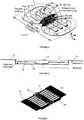
- FIG. 1 shows a layout for a circular power pad.
- the core structure comprises a number of radially directed strips 2 of magnetically permeable material such as ferrite.
- a pad measuring 700 millimetres in diameter (Pd in Figure 1 ) has been built using readily available I93 cores (three per radial strip).
- One or more substantially planar coils 4 are located on top of the core structure.
- shielding comprising a backing plate 6 made of a sheet material, preferably aluminium, which has a peripheral edge in the form of a ring 8 (i.e.
- the aluminium backing 6 and ring 8 add robustness and provide shielding around the pad to leakage fluxes which may exist.
- the ring 8 in prior art circular pads is located immediately adjacent to the edge of the core i.e. the outer end of each radial ferrite strip 2.
- the material from which the backing structure 6 and ring 8 is constructed is preferably one which repels magnetic flux.
- the material is also preferably a good conductor and not lossy.
- the backing 6 may comprise a plate material or a mesh material e.g. aluminium plate or aluminium mesh.
- the backing material may comprise a combination of materials, for example a plate that supports the core, and a mesh section that extends beyond the core perimeter. Advantages associated with use of a mesh material include lower cost, improved integration with the surrounding substrate (in a roadway application for example) and improved transfer of heat from the structure to the surrounding environment.
- Magnetic field leakage has been investigated by simulation since simulation results have been shown to match experimental results to within a few percent.
- a transmitter pad is excited with a sinusoidal 23A current at 20kHz and an open circuit receiver pad is placed 125mm above it.
- the magnetic flux density is recorded along a 1m contour extending from the centre of the air gap between the pads outward.
- the flux density is significantly lower above the receiver (being the upper pad) and below the transmitter due to shielding from the aluminium backing plate.
- Fig. 4 where various field leakage curves are plotted.
- the flux vectors in Fig. 2(a) show the ring creates a higher reluctance path by causing the field to bend thereby reducing leakage. This 'flux catching' approach results in lower power transfer. Therefore a plate without a ring provides a compromise between leakage and coupling. Flux is easily able to enter the ferrite strips through their ends resulting in increased power.
- Figs 2 , 3 and 4 illustrate pad sensitivity to metallic objects in the vicinity of the pad.
- the chassis of an EV is typically made out of steel and this can severely reduce the quality factor of the receiver or transmitter pads Q L (where Q L is the reactance of the coil divided by its resistance at the frequency of operation). Larger leakage results in more energy lost in the surrounding EV chassis - this loss is proportional to B 2 , thus slight reductions in flux density can be very effective.
- Fig. 4 shows that the ring reduces the area through which flux can escape, but the flux that does escape tends to curve inwards to the opposite pad. Consequently, this flux leakage is less likely to run parallel to the surrounding chassis. Conversely, when the ring is removed as shown in Fig. 2(b) (the back plate is still present), this shaping of the flux path is reduced, and flux is allowed to travel unimpeded toward the chassis, resulting in larger leakage and hence larger loss.
- simply providing a shielding plate with a flange that extends beyond a perimeter of the core may be advantageous.
- providing a lip (such as a ring) so that the flange structure provides a recess or gap between the core and the lip can also be advantageous.
- the International Commission on Non-Ionizing Radiation Protection has produced guidelines that prescribe limits to human exposure to time varying magnetic fields.
- the body average limit is 27 ⁇ T in the range of 3kHz-10MHz (though above 100kHz RF specific levels must be considered). Spot limits can be greater, but their magnitude must be defined by the standards bodies for each country.
- the 700mm circular pads with a ring positioned with a ⁇ Al of 40mm have spot values less than 27 ⁇ T at points greater than 500mm away from the pad centre and therefore the body average will be significantly lower.
- FIG. 5 Another pad topology which eliminates unwanted rear flux paths by placing two coils above (rather than around) the ferrite strips 2 which form the core, is shown in Figure 5 .
- the ferrite channels the main flux behind the coils (referenced a and b) and forces the flux to establish itself on one side, being the side on which the coils are located. Therefore, any aluminum (not shown in Figure 5 ) provided beneath the core only needs to shield stray fields, resulting in negligible loss.
- the ideal flux paths are shown in Figure 5 arching above the pad. These paths allow good coupling to a similar shaped receiver because the fundamental height (h z ) is essentially proportional to 1 ⁇ 2 of the pad length.
- a key feature to achieving a high coupling factor between two power pads is the intra-pad coupling.
- the height of the intra-pad flux ( ⁇ ip ) is controlled by adjusting the width of the coils a and b in the region where they are immediately adjacent to each other. This region is shaded in Fig. 5 , and referred to as a "flux pipe" between coil a and coil b.
- the fraction of flux ⁇ ip that couples to the receiver pad is mutual flux ( ⁇ M ), therefore the section of coil forming the flux pipe should ideally be made as long as possible.
- the remaining length of the coil should ideally be minimized to save copper and lower R ac . Doing so results in coils shaped like a "D" and since there are two such coils placed back to back, the pad is referred to as a Double D (DD) structure in this document.
- DD Double D
- a backing structure may be used to control the shape of the field in front of the pad and/or to eliminate any fields that happen to propagate around the sides or rear of the pad.
- the effect of such a backing structure or flux shaping structure on the DD pad, and variants of that pad, are discussed below.
- FIG. 13A a design of DD pad for which the backing or shielding plate 16 has an extended flange 16a of 50mm is illustrated.
- Figure 13B shows the further addition of a ring 16b of 5mm thickness.
- Figure 13C A plan view which includes dimensions (in mm) of the simulated structures is shown in Figure 13C .
- the structure of the DD transmitter has 4 rows of 6 ferrite slabs, while the receiver has 4 rows of 8 ferrite slabs.
- the air gap between the transmitter pad and receiver pad is 125mm with no offset.
- the Isc was measured to quantify the power capability (P su ) and the leakage field (B_leakage) was taken at 1m from the centre of the pad in the plane of the pad.
- a coaxial winding 10 was wound about the core 2 so that the return conductors are shielded using a cage 12 formed in the backing /shielding plate 16.
- the plate 16 extends beyond the periphery of the core 2 at the longitudinal ends of the core, forming flanges or end plates 14.
- the design aims to have almost circular flux paths so that maximum flux path height and coupling can be achieved.
- the design is presented in figures 6 and 7 .
- FIG. 8 and 9 This design contains the coaxial winding that goes through the coaxial cage (similar to the Double D Coax of figures 7 and 8 ), as well as Double D windings (similar to the windings a and b of the Double D structure referred to above with reference to Figure 5 ).
- the design shown in Figures 8 and 9 aims to use the Double D windings to further shape the fields and hence increase coupling and reduce leakage fields.
- the design resulting from the optimisation process is shown in Figure 11 .
- the aluminium provides an outer portion with an upwardly directed lip, and a flange peripheral from or dependent from the lip.
- the cage is not required in the Figure 11 construction.
- Figure 12 shows the resulting flux density plot for the design of Figure 11 .
- the backing structure aluminium sheet material
- each coil is wound as a flat spiral but are shown here as a 2 dimensional cross section.
- Each coil comprises 20 turns, so there are 40 wires in the central flux pipe.
- the wires in the flux pipe i.e. between the pole area are all placed with centres 6.6 mm apart, and the end windings 21, 22 in the coils (i.e. those windings at the longitudinal ends of the core) are 20 turns spaced with centres 4 mm apart (essentially touching).
- ferrite 23 has been placed on top of the end windings 21, 22.
- An aluminium separator 16 formed from sheet material has been added to prevent a magnetic short circuit condition.
- the aluminium is located behind core 2 and flanges extend beyond the periphery of the core at the longitudinal ends of the core.
- the flux path is essentially ideal above the ferrite but has some serious undesirable end fluxes below the bottom of the pad.
- With eight ferrite cores in the pad the aluminium 16 transitions between the third and fourth cores, and between the sixth and seventh cores, and covers the ends of the first and eighth cores. In this way the flux pattern of Figure 16B is almost the same as 16A apart from these end fluxes.
- the aluminium plate 16 has been altered so that the flange portions provide a coaxial cage at each end.
- the ferrite 23 is split to be above and below the end windings 21, 22, and the ferrite and end windings are provided within the cage areas.
- the ferrite associated with the end windings has a gap in it. If the gap is not there and the whole space except the winding was filled with ferrite then the inductance of the end windings would be very high but the gap may be varied from a small gap to no ferrite at all to control the effect of the end windings on the flux pattern. As shown in Figure 16D , the unwanted end fluxes are substantially eliminated.
Landscapes
- Engineering & Computer Science (AREA)
- Power Engineering (AREA)
- Transportation (AREA)
- Mechanical Engineering (AREA)
- Computer Networks & Wireless Communication (AREA)
- Physics & Mathematics (AREA)
- Electromagnetism (AREA)
- Regulation Of General Use Transformers (AREA)
- Current-Collector Devices For Electrically Propelled Vehicles (AREA)
- Electric Propulsion And Braking For Vehicles (AREA)
- Shielding Devices Or Components To Electric Or Magnetic Fields (AREA)
Description
- This invention relates to apparatus and methods for shaping or directing magnetic fields generated or received by magnetic flux generating or receiving apparatus used in inductive power transfer (IPT) systems.
- IPT systems are well known. As discussed in international patent application
WO 2010/090539 , it is necessary in some IPT applications, such as electric vehicle charging, to provide a loosely coupled system capable of operating with a large air gap between the magnetic flux transmitting and receiving structures. - Due to the potential for large scale deployment of both stationary charging and roadway powered electric vehicle applications, magnetic flux transmitting and receiving structures that operate efficiently with minimum use of materials are highly desirable.
- Apart from efficiency, another issue with loosely coupled systems is elimination or control of stray magnetic fields which may pose health risks, and which in most countries are required to be controlled within certain limits by law. Further examples of IPT systems displaying different topologies and modes of operation are known from
US5000178 disclosing a solenoid topology with windings wrapped around a high permeability bar,WO2010/098547 A2 disclosing an elongated E-core topology with conductors running along a road within recesses between portions within the core andWO2005/024865 A2 disclosing a coil wound around a former, which is in the form of thin sheet of magnetic material. - It is an object of the invention to provide an improved apparatus or method for inductive power transfer, or an improved IPT power transfer pad, or to at least provide the public or the industry with a useful alternative. The invention is set out by the appended claims.
- Accordingly one aspect the invention broadly provides an IPT system magnetic flux device for coupling with another device to transfer power inductively, the device comprising a magnetically permeable core means and at least one planar coil magnetically associated with the core means, and a shield means for shaping the magnetic flux for coupling and provided on the opposite side of the core means, the shield means comprising an outer portion having a periphery that extends beyond at least part of a perimeter of the core means, a lip extending from the periphery of the outer portion, and a flange extending from the lip; wherein the outer portion extends from the device substantially in a plane of the core means, and the lip (8) is provided at an angle relative to the outer portion; wherein the angle is between substantially 90 degrees and 150 degrees relative to the outer portion.
- In an embodiment the shield means comprises a sheet material.
- Preferably the device comprises a pad.
- Preferably the outer portion has a peripheral edge, and there is a gap between the core perimeter and the peripheral edge. In one embodiment the gap may be filled or partially filled with a non-magnetic material.
- In one embodiment the outer portion substantially circumscribes the core.
- Preferably the outer portion further comprises a flange peripheral of the lip. In one embodiment said flange is in a plane substantially parallel to the first portion.
- Preferably the coil is a substantially planar coil.
- Preferably the coil is provided on the side of the core opposite to the shield.
- In a further embodiment the shield further comprises a cage. The cage is adapted to receive one or more windings. In one embodiment the cage comprises a box section.
- Preferably the sheet material comprises a plate.
- Alternatively the sheet material comprises a mesh material.
- Alternatively the sheet material comprises one or more sections of plate and one or more sections of mesh.
- Preferably the sheet material includes a flange which extends beyond the perimeter of the core.
- Preferably the core has a longitudinal axis and the outer portion of the shield extends beyond each longitudinal end of the core.
- Preferably the sheet material is constructed from aluminium.
- Preferably the cage is provided on a first side of the core, such that one or more turns of the coil on the first side of the core pass through the cage.
- Alternatively the cage is provided at one end of the core, a further cage means is provided at an opposite end of the core and a further coil is provided whereby one or more turns of the coil pass through the cage means and one or more turns of the further coil pass through the further cage means.
- Further aspects of the invention will become apparent from the following description.
- One or more embodiments of the invention will be described below with reference to the accompanying drawings in which:
- Figure 1
- is a plan view of a circular inductive power transfer pad;
- Figures 2A & B
- are graphs showing variation in Psu and mutual inductance for two identical coupled pads having the same inductance for variations in the ratio of coil diameter with respect to pad diameter;
- Figure 3
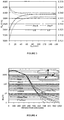
- is a graph showing variations in Psu with the outer portion (δAl) i.e. the distance between the core periphery and the outer pad diameter defined by the backing plate or shield;
- Figure 4
- shows B as a function of distance for the pad of
Figure 1 ; - Figure 5
- is perspective view of a Double D pad;
- Figure 6
- is an elevation in cross section showing one embodiment of a pad structure;
- Figure 7
- is a perspective view of the pad of
Figure 6 ; - Figure 8
- is an elevation in cross section showing another embodiment of a pad construction;
- Figure 9
- is a perspective view of the construction of
Figure 8 ; - Figure 10
- shows an elevation in cross section for the pad shown in
Figures 8 and 10 , but identifies dimensions for the shield structure; - Figure 11
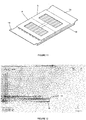
- is a perspective view of a further pad structure;
- Figure 12
- is a partial cross section showing the pad structure of
Figure 11 and the field when the pad is energised; - Figure 13
- shows a pad structure for a Double D pad;
- Figures 14 & 15
- show variation in B with distance for pad structures of
Figures 13B and 13C compared with a structure having a backing plate or shield which does not extend beyond the core periphery; - Figures 16A to 16F
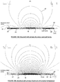
- show elevations in cross section through a variety of different pad embodiments, and representations of the magnetic field generated by each embodiment.
- As discussed above, the magnetic structures or devices that are used to generate and receive magnetic flux in order to provide coupling between the primary and secondary circuits of an IPT system may take a variety of forms. The structures are often referred to as pads since they usually extend further in two dimensions than the third dimension. The third dimension is usually a thickness which is intended to be minimised so that the pad structure can be incorporated in the other side of a vehicle and/or in a roadway, a parking space and a garage floor for example.
- One known pad structure is disclosed in
WO 2008/140333 which is generally circular in design.Figure 1 shows a layout for a circular power pad. As can be seen from that figure, the core structure comprises a number of radially directedstrips 2 of magnetically permeable material such as ferrite. In one example, a pad measuring 700 millimetres in diameter (Pd inFigure 1 ) has been built using readily available I93 cores (three per radial strip). One or more substantiallyplanar coils 4 are located on top of the core structure. On the opposite side of the core structure (i.e. underneath) is provided shielding comprising abacking plate 6 made of a sheet material, preferably aluminium, which has a peripheral edge in the form of a ring 8 (i.e. an upwardly directed flange) at the periphery of an outer portion (δAl) of the shield. Thealuminium backing 6 andring 8 add robustness and provide shielding around the pad to leakage fluxes which may exist. Unlike the pad inFigure 1 , thering 8 in prior art circular pads is located immediately adjacent to the edge of the core i.e. the outer end of eachradial ferrite strip 2. - Symbols in
Figure 1 are as follows: - FeW
- Ferrite width
- FeL
- Ferrite length
- δA1
- Extended Rad.
- Cd
- Coil Dia.
- Pd
- Pad Diameter
- CW
- Coil width
- I1
- 23A at 20kHz
- The material from which the
backing structure 6 andring 8 is constructed is preferably one which repels magnetic flux. The material is also preferably a good conductor and not lossy. Thebacking 6 may comprise a plate material or a mesh material e.g. aluminium plate or aluminium mesh. Also, the backing material may comprise a combination of materials, for example a plate that supports the core, and a mesh section that extends beyond the core perimeter. Advantages associated with use of a mesh material include lower cost, improved integration with the surrounding substrate (in a roadway application for example) and improved transfer of heat from the structure to the surrounding environment. - We have found that placing the
ring 8 close to the core periphery reduces leakage flux, but is not ideal because it has an adverse effect on coupling. As discussed further below, extending thering 8 andbacking plate 6 beyond the outer periphery of the core can lead to optimizing coupling for a given field leakage. - Our previous work has shown that the ideal coil diameter of the circular pad is 57% of the pad diameter that includes an aluminium ring. To investigate further, a simulation has been performed in which the coil diameter (Cd) was varied on a 700 millimetre diameter pad with an aluminium ring (R), and without an aluminium ring (NR), at a vertical separation of 125mms.
- The results are shown in
Figure 2a and 2b which show the Psu (open circuit voltage multiplied by short circuit current) and coupling factor k. The assumption is that the transmitter and receiver pads are both identical and have the same inductance. As can be seen, there is a significant increase in power if the ring is removed. For a pad without a ring a core diameter of 416mm (approximately 60% of the pad diameter) is a good compromise between the power transferred and the coupling co-efficient. As shown inFigure 2b , the pad self inductance drops sharply as the coil gets very close to the ring, whereas it drops relatively slowly if the ring is removed. The ring effectively cancels the flux from the coil due to opposing flux from any currents that reduce the inductance. - When the coil is roughly centred on a pad with a ring (∼0.55<Cd/Pd<∼0.7), flux is able to enter and exit from the ends of the ferrite resulting in increased inductance. For a pad without a ring, the maximum inductance results with a Cd of 200mm however it appears that the flux on the outside edge of the coil only has a small area through which it can enter the ferrite strip - the ferrite distribution is not radially symmetrical about the coil. This can be explained in terms of inductance that determines how much energy a pad can store in its magnetic field. Flux lines tend to arrange themselves to minimize energy storage by traversing the paths of least reluctance. There is no flux out the back of the pads due to their construction; a coil sits on ferrite that sits on a layer of aluminium shielding. Assuming Cd is less than its ideal value, the flux lines would repel each other more on the inside of the coil because there is less volume for the flux on the inside of the coil (the number of flux lines linking the coil is constant). With Cd optimized, the overall field "repulsion" is minimized due to the increased volume on the inside of the coil thus the stored energy and hence inductance for this particular arrangement is maximized.
- The results shown in
Fig. 2(b) indicate that pad inductance drops when a ring is added due to a flux cancelling effect. Reducing flux leakage at the expense of power transfer is often necessary to ensure high power systems are able to meet magnetic field leakage standards. Thus, in order to separately determine the effect of the ring and backing plate on power transfer, simulations were undertaken where the outer portion of the sheet material beyond the core periphery (δAl) was varied with and without a ring. Psu and k profiles are shown inFig. 3 . Here the label "R" implies both the backing plate and ring are present while the label "P" indicates only the extended backing plate is present. M represents mutual inductance between transmitter and receiver pads, and L2 represents the inductance of the receiver pad. Placing the ring close to the ends of the ferrite significantly reduces performance given Psu increases by ∼27% when it is removed. Pads with and without rings reach a Psu of 3.9kVA however by this point the diameter has increased by 170mm. - The Psu profiles diverge slightly when δAl> 100mm showing the ring has a slight 'flux catching' effect. An outer portion δAl of 40mm is therefore suggested for the optimized pad because there is little increase in performance and smaller pads are preferable.
- Magnetic field leakage has been investigated by simulation since simulation results have been shown to match experimental results to within a few percent. Here a transmitter pad is excited with a sinusoidal 23A current at 20kHz and an open circuit receiver pad is placed 125mm above it. The magnetic flux density is recorded along a 1m contour extending from the centre of the air gap between the pads outward. The flux density is significantly lower above the receiver (being the upper pad) and below the transmitter due to shielding from the aluminium backing plate. The results are shown in
Fig. 4 where various field leakage curves are plotted. The first labelled "No ring" shows the output without a ring and having δAl =0. This is compared against other designs with the ring in place but having increasing values for δAl. The '40mm Plate' contour (having δAl = 40mm without the ring) is also added since this was described as ideal from a power perspective. Removing the ring increases flux leakage substantially as does placing it very close to the ferrite ends. A larger backing plate attenuates leakage slightly but a ring is required for the greatest reduction. Field leakage reduces as δAl increases but this increases Psu favourably (as shown inFig. 3 ). In a receiver pad the upper limit of outer portion δAl is determined by the maximum space available on an EV chassis and the extra cost for the additional aluminum. The flux vectors inFig. 2(a) show the ring creates a higher reluctance path by causing the field to bend thereby reducing leakage. This 'flux catching' approach results in lower power transfer. Therefore a plate without a ring provides a compromise between leakage and coupling. Flux is easily able to enter the ferrite strips through their ends resulting in increased power. - The measurements in
Figs 2 ,3 and 4 illustrate pad sensitivity to metallic objects in the vicinity of the pad. The chassis of an EV is typically made out of steel and this can severely reduce the quality factor of the receiver or transmitter pads QL (where QL is the reactance of the coil divided by its resistance at the frequency of operation). Larger leakage results in more energy lost in the surrounding EV chassis - this loss is proportional to B2, thus slight reductions in flux density can be very effective.Fig. 4 shows that the ring reduces the area through which flux can escape, but the flux that does escape tends to curve inwards to the opposite pad. Consequently, this flux leakage is less likely to run parallel to the surrounding chassis. Conversely, when the ring is removed as shown inFig. 2(b) (the back plate is still present), this shaping of the flux path is reduced, and flux is allowed to travel unimpeded toward the chassis, resulting in larger leakage and hence larger loss. - Thus in some applications, simply providing a shielding plate with a flange that extends beyond a perimeter of the core may be advantageous. Also, providing a lip (such as a ring) so that the flange structure provides a recess or gap between the core and the lip can also be advantageous.
- The International Commission on Non-Ionizing Radiation Protection (ICNIRP) has produced guidelines that prescribe limits to human exposure to time varying magnetic fields. The body average limit is 27µT in the range of 3kHz-10MHz (though above 100kHz RF specific levels must be considered). Spot limits can be greater, but their magnitude must be defined by the standards bodies for each country. The 700mm circular pads with a ring positioned with a δAl of 40mm have spot values less than 27 µT at points greater than 500mm away from the pad centre and therefore the body average will be significantly lower. This spot value of 27 µT is reached at a distance of ∼540mm if the ring is removed (δAl= 40mm) and at ∼600mm if the ring is removed from the original pad (δAl = 0mm). These distances are easily acceptable given the width dimensions of typical vehicles, however if higher power levels over larger air gaps are required the ring may need further extension.
- Another pad topology which eliminates unwanted rear flux paths by placing two coils above (rather than around) the ferrite strips 2 which form the core, is shown in
Figure 5 . The ferrite channels the main flux behind the coils (referenced a and b) and forces the flux to establish itself on one side, being the side on which the coils are located. Therefore, any aluminum (not shown inFigure 5 ) provided beneath the core only needs to shield stray fields, resulting in negligible loss. The ideal flux paths are shown inFigure 5 arching above the pad. These paths allow good coupling to a similar shaped receiver because the fundamental height (hz) is essentially proportional to ½ of the pad length. A key feature to achieving a high coupling factor between two power pads is the intra-pad coupling. The height of the intra-pad flux (φip) is controlled by adjusting the width of the coils a and b in the region where they are immediately adjacent to each other. This region is shaded inFig. 5 , and referred to as a "flux pipe" between coil a and coil b. The fraction of flux φip that couples to the receiver pad is mutual flux (φM), therefore the section of coil forming the flux pipe should ideally be made as long as possible. Conversely, the remaining length of the coil should ideally be minimized to save copper and lower Rac. Doing so results in coils shaped like a "D" and since there are two such coils placed back to back, the pad is referred to as a Double D (DD) structure in this document. - Again, a backing structure may be used to control the shape of the field in front of the pad and/or to eliminate any fields that happen to propagate around the sides or rear of the pad. The effect of such a backing structure or flux shaping structure on the DD pad, and variants of that pad, are discussed below.
- The effect of a simple planar outer portion extension of the aluminium backing plate about the perimeter of a DD pad structure has been investigated, along with the provision of a peripheral edge such as a ring (in the form of an upstanding, angled or vertical lip provided as part of an extended flange). Referring to
Figure 13A , a design of DD pad for which the backing or shieldingplate 16 has an extendedflange 16a of 50mm is illustrated.Figure 13B shows the further addition of aring 16b of 5mm thickness. A plan view which includes dimensions (in mm) of the simulated structures is shown inFigure 13C . The structure of the DD transmitter has 4 rows of 6 ferrite slabs, while the receiver has 4 rows of 8 ferrite slabs. The air gap between the transmitter pad and receiver pad is 125mm with no offset. - As shown in
Figures 14 and15 , the pad structures ofFigures 13B and 13C were compared with a structure for which the backing plate did not have a ring and did not extend beyond the core (referred to inFigures 14 and15 as "Orig"). We found that extending the aluminium improves power transfer by 2.5%, while extending the aluminium and adding a ring improves power transfer by 5%. Both extensions help the far field magnetic leakage. However, the field in the centre is not changed significantly - as expected given that the power improves. - To compare other possible design modifications for the DD pad structure, two main quantities were measured from JMAG simulations. The Isc was measured to quantify the power capability (Psu) and the leakage field (B_leakage) was taken at 1m from the centre of the pad in the plane of the pad.
- However, when the designs are optimised, these variables vary significantly. As there are two variables that are changing, it is often difficult to fully quantify the overall effect of the optimisation process. Hence, the results are modified so that only one of these variables changes at a time. This is done by scaling the track current so that the leakage field at 1m is maintained at a constant level. For example, as a certain design parameter is varied, the Isc and B_leakage are obtained. Following this, the track current is scaled appropriately so the leakage field is maintained at a reference level. This reference level is set to be the leakage field produced by a standard Double D pad. As a result, the various proposed designs can be easily compared to the existing Double D pads. It should be noted, that as a result of the scaling of the track current, the Psu of the system is also scaled correspondingly. The next section shows the various designs that were considered.
- A coaxial winding 10 was wound about the
core 2 so that the return conductors are shielded using acage 12 formed in the backing /shielding plate 16. Theplate 16 extends beyond the periphery of thecore 2 at the longitudinal ends of the core, forming flanges orend plates 14. The design aims to have almost circular flux paths so that maximum flux path height and coupling can be achieved. The design is presented infigures 6 and 7 . - Following this a further modification was proposed, and is shown in
Figures 8 and 9 . This design contains the coaxial winding that goes through the coaxial cage (similar to the Double D Coax offigures 7 and8 ), as well as Double D windings (similar to the windings a and b of the Double D structure referred to above with reference toFigure 5 ). The design shown inFigures 8 and 9 aims to use the Double D windings to further shape the fields and hence increase coupling and reduce leakage fields. - From this design, an optimisation process was undertaken. In the optimisation process, several parameters were varied and their effects were quantified. The parameters that were varied are shown graphically in
Figure 10 . As a result the coaxial winding 10 was removed, and the optimum values chosen are summarised below: - Number of Double D windings (optimum N = 20, i.e. similar winding to current Double D of
Figure 5 ) - Aluminium (i.e. backing) lengths (optimum basin length = 75mm, aluminium angle = 45deg and the endplate length = 50mm).
- The design resulting from the optimisation process is shown in
Figure 11 . Thus the aluminium provides an outer portion with an upwardly directed lip, and a flange peripheral from or dependent from the lip. Although shown, the cage is not required in theFigure 11 construction. -
Figure 12 shows the resulting flux density plot for the design ofFigure 11 . The backing structure (aluminium sheet material) plays an important part in shaping the fields through the induction of eddy currents in the aluminium structure. - Using the approach outlined earlier, the proposed design was compared to the present Double D pad. The results are as shown below:
Psu for same B_leakage as present Double D (VA) % Increase in Psu for same B_leakage as present Double D (%) B_leakage (at 1 m) with track current scaling (T) Present Double D ( Figure 5 Structure)1235.154 0 2.4350E-05 Proposed Design ( Figure 11 Structure)2369.314 91.823 2.4350E-05 - It can be seen that the design of
Figure 11 provides a significant increase in the amount of power that can be coupled across the air gap for the same B_leakage as the Double D structure ofFigure 5 . This result is a little misleading as most of the improvement comes about from the increase in the number of rows of ferrite from 6 inFig 5 to 8 inFigure 11 , but the flanges add another 10-15%. - We now consider other coil and aluminium shielding arrangements for the general double D structure with reference to
Figures 16A - 16F . In these figures the two coils are each wound as a flat spiral but are shown here as a 2 dimensional cross section. Each coil comprises 20 turns, so there are 40 wires in the central flux pipe. The wires in the flux pipe i.e. between the pole area are all placed with centres 6.6 mm apart, and theend windings centres 4 mm apart (essentially touching). This arrangement without any aluminium shielding and with the end windings located beyond the ends of thecore 2 produces the flux pattern (thecurved lines 18 about the cross section through the pad structure) ofFigure 16A . This flux pattern is very high but has spillage of flux out the ends of the coils. Here the height and spillage are both amplified by having no ferrite under the end windings. In practice this spillage flux is undesirable, for reasons set out earlier in this document, and is very difficult to reduce. - In
Figure 16B ferrite 23 has been placed on top of theend windings aluminium separator 16 formed from sheet material has been added to prevent a magnetic short circuit condition. The aluminium is located behindcore 2 and flanges extend beyond the periphery of the core at the longitudinal ends of the core. As shown inFigure 16B the flux path is essentially ideal above the ferrite but has some serious undesirable end fluxes below the bottom of the pad. With eight ferrite cores in the pad thealuminium 16 transitions between the third and fourth cores, and between the sixth and seventh cores, and covers the ends of the first and eighth cores. In this way the flux pattern ofFigure 16B is almost the same as 16A apart from these end fluxes. - In
Figure 16C theferrite 23 has been removed and placed below theend windings - In
Figure 16D thealuminium plate 16 has been altered so that the flange portions provide a coaxial cage at each end. Theferrite 23 is split to be above and below theend windings Figure 16D , the unwanted end fluxes are substantially eliminated. - Turning to
Figure 16E , theferrite 23 has been removed so that theend windings aluminium 16 may be high. The losses may be reduced by spreading theend windings Figure 16F to get an excellent flux pattern. - The addition of an extended aluminium shield and flange is also helpful in other transmitter and receiver topologies such as the bipolar topology described in
WO 2011/016737 .
Claims (15)
- An inductive power transfer, IPT, system magnetic flux device for generating or receiving a magnetic flux for coupling with another device to transfer power inductively, the magnetic flux device comprising:a magnetically permeable core means (2);at least one planar coil (4, a, b) provided on a first side of the core means and magnetically associated with the core means, and;a shield means (6, 16) for shaping the magnetic flux for coupling and provided on a side of the core means opposite to the first side, the shield means comprising an outer portion having a periphery that extends beyond at least part of a perimeter of the core means (2), a lip (8) extending from the periphery of the outer portion, and a flange (14) extending from the lip (8);wherein the outer portion extends from the device substantially in a plane of the core means (2), and the lip (8) is provided at an angle relative to the outer portion;wherein the angle is between substantially 90 degrees and 150 degrees relative to the outer portion.
- An IPT system magnetic flux device as claimed in claim 1 wherein the shield means (6, 16) comprises a sheet material.
- An IPT system magnetic flux device as claimed in claim 1 or claim 2 wherein a gap is present between the core perimeter and the lip (8) to allow magnetic flux for coupling to escape from the core means (2).
- An IPT system magnetic flux device as claimed in claim 3 wherein the gap is filled or partially filled with a non-magnetic material.
- An IPT system magnetic flux device as claimed in any one of the preceding claims wherein the outer portion substantially circumscribes the core means (2).
- An IPT system magnetic flux device as claimed in any one of the preceding claims wherein said flange (14) is in a plane substantially parallel to a plane that the outer portion lies within.
- An IPT system magnetic flux device as claimed in any one of the previous claims wherein the shield means (16) further comprises a cage (12) for shielding a conductor of a further coil.
- An IPT system magnetic flux device as claimed in any one of claims 1 to 6 wherein the shield means (16) further comprises a cage (12) for shielding a conductor of the coil, and wherein the flange comprises a wall of the cage (12).
- An IPT system magnetic flux device as claimed in any one of the preceding claims wherein the flange (14) extends from the lip substantially adjacent to the first side of the core means.
- An IPT system magnetic flux device as claimed in any one of the preceding claims wherein the coil (4, a, b) comprises a flat coil.
- An IPT system magnetic flux device as claimed in any one of the preceding claims wherein the coil (4, a, b) is provided in a first layer, the core means (2) is provided in a second layer.
- An IPT system magnetic flux device as claimed in any one of the preceding claims wherein the shield means repels magnetic flux.
- An IPT system magnetic flux device as claimed in any one of the preceding claims wherein the shield means comprises aluminum sheet.
- An IPT system magnetic flux device as claimed in any one of the preceding claims wherein the coil has a circular topology.
- An IPT system magnetic flux device as claimed in any one of the preceding claims further comprising a second planar coil arranged into one of the following topologies: the coils are arranged adjacent each other in substantially the same plane; the coils form a bipolar topology.
Applications Claiming Priority (2)
| Application Number | Priority Date | Filing Date | Title |
|---|---|---|---|
| NZ59505611 | 2011-09-07 | ||
| PCT/NZ2012/000160 WO2013036146A1 (en) | 2011-09-07 | 2012-09-07 | Magnetic field shaping for inductive power transfer |
Publications (3)
| Publication Number | Publication Date |
|---|---|
| EP2751900A1 EP2751900A1 (en) | 2014-07-09 |
| EP2751900A4 EP2751900A4 (en) | 2015-05-27 |
| EP2751900B1 true EP2751900B1 (en) | 2021-08-04 |
Family
ID=47832425
Family Applications (1)
| Application Number | Title | Priority Date | Filing Date |
|---|---|---|---|
| EP12829832.0A Active EP2751900B1 (en) | 2011-09-07 | 2012-09-07 | Magnetic field shaping for inductive power transfer |
Country Status (6)
| Country | Link |
|---|---|
| US (1) | US10263466B2 (en) |
| EP (1) | EP2751900B1 (en) |
| JP (1) | JP6407024B2 (en) |
| KR (1) | KR101970322B1 (en) |
| CN (2) | CN103947072A (en) |
| WO (1) | WO2013036146A1 (en) |
Families Citing this family (32)
| Publication number | Priority date | Publication date | Assignee | Title |
|---|---|---|---|---|
| CN102625750B (en) | 2009-08-07 | 2015-04-15 | 奥克兰联合服务有限公司 | Roadway powered electric vehicle system |
| US20150236513A1 (en) * | 2012-02-16 | 2015-08-20 | Auckland Uniservices Limited | Multiple coil flux pad |
| KR102227449B1 (en) * | 2013-03-27 | 2021-03-15 | 오클랜드 유니서비시즈 리미티드 | Electromagnetic field confinement |
| US9676285B2 (en) | 2013-05-01 | 2017-06-13 | Qualcomm Incorporated | Vehicle charging pad having reduced thickness |
| EP3080825B1 (en) | 2013-11-13 | 2020-12-23 | Apple Inc. | Transmitter for inductive power transfer systems |
| US9837204B2 (en) * | 2013-12-17 | 2017-12-05 | Qualcomm Incorporated | Coil topologies for inductive power transfer |
| CN103746465A (en) * | 2014-01-17 | 2014-04-23 | 杭州信多达电器有限公司 | Wireless charging emission coil assembly |
| JP2015142019A (en) * | 2014-01-29 | 2015-08-03 | トヨタ自動車株式会社 | Power receiving device |
| WO2015178780A1 (en) | 2014-05-19 | 2015-11-26 | Powerbyproxi Limited | Magnetically permeable core and inductive power transfer coil arrangement |
| WO2015178781A1 (en) | 2014-05-19 | 2015-11-26 | Powerbyproxi Limited | Magnetically permeable core and an inductive power transfer coil arrangement |
| JP6519773B2 (en) * | 2014-05-22 | 2019-05-29 | 株式会社デンソー | Power transmission pad and contactless power transmission system |
| US9812875B2 (en) | 2014-09-05 | 2017-11-07 | Qualcomm Incorporated | Systems and methods for adjusting magnetic field distribution using ferromagnetic material |
| CN115831569A (en) * | 2014-09-11 | 2023-03-21 | 奥克兰联合服务有限公司 | Flux coupling structure with controlled flux cancellation |
| US9941708B2 (en) | 2014-11-05 | 2018-04-10 | Qualcomm Incorporated | Systems, methods, and apparatus for integrated tuning capacitors in charging coil structure |
| US9960607B2 (en) | 2014-12-29 | 2018-05-01 | Qualcomm Incorporated | Systems, methods and apparatus for reducing intra-base array network coupling |
| GB2535463A (en) * | 2015-02-16 | 2016-08-24 | Bombardier Transp Gmbh | Power transfer unit of a system for inductive power transfer, a method of manufacturing a power transfer unit and of operating a power transfer unit |
| US9929606B2 (en) * | 2015-05-11 | 2018-03-27 | Qualcomm Incorporated | Integration of positioning antennas in wireless inductive charging power applications |
| KR20180040525A (en) * | 2015-06-26 | 2018-04-20 | 봄바디어 프리모베 게엠베하 | A primary-sided and a secondary-sided arrangement of winding structures, a system for inductive power transfer and a method for inductively supplying power to a vehicle |
| WO2017204663A1 (en) | 2016-05-25 | 2017-11-30 | Powerbyproxi Limited | A coil arrangement |
| WO2017209630A1 (en) | 2016-06-01 | 2017-12-07 | Powerbyproxi Limited | A powered joint with wireless transfer |
| US20180131242A1 (en) | 2016-11-04 | 2018-05-10 | Powerbyproxi Limited | Inductive power transmitter, receiver and method of operation |
| CN206834025U (en) | 2016-11-18 | 2018-01-02 | 鲍尔拜普罗克西有限公司 | Induction type power transmission line coil assembly |
| US10978911B2 (en) | 2016-12-19 | 2021-04-13 | Apple Inc. | Inductive power transfer system |
| US20180233961A1 (en) | 2017-02-14 | 2018-08-16 | Aiguo Hu | Inductive power transfer |
| WO2019108071A1 (en) * | 2017-12-01 | 2019-06-06 | Auckland Uniservices Limited | A misalignment tolerant hybrid wireless power transfer system |
| US11207541B2 (en) | 2018-03-23 | 2021-12-28 | Regenesis Biomedical, Inc. | High-power pulsed electromagnetic field applicator systems |
| US10593468B2 (en) | 2018-04-05 | 2020-03-17 | Apple Inc. | Inductive power transfer assembly |
| US11547848B2 (en) | 2018-06-21 | 2023-01-10 | Regenesis Biomedical, Inc. | High-power pulsed electromagnetic field applicator systems |
| US11833363B2 (en) | 2019-10-25 | 2023-12-05 | Regenesis Biomedical, Inc. | Current-based RF driver for pulsed electromagnetic field applicator systems |
| CN111463000B (en) * | 2020-05-20 | 2021-08-24 | 河北工业大学 | Combined type shielding structure suitable for wireless power supply system of electric automobile |
| WO2022175714A1 (en) * | 2021-02-17 | 2022-08-25 | Daymak Inc. | Wireless power transfer (wpt) charging system for an electric vehicle |
| WO2022261172A1 (en) * | 2021-06-09 | 2022-12-15 | Regenesis Biomedical, Inc. | Method and apparatus for providing pulsed electromagnetic field therapy |
Family Cites Families (22)
| Publication number | Priority date | Publication date | Assignee | Title |
|---|---|---|---|---|
| US5000178A (en) * | 1986-05-23 | 1991-03-19 | Lti Biomedical, Inc. | Shielded electromagnetic transducer |
| GB9025391D0 (en) | 1990-11-22 | 1991-01-09 | Rue Company The Plc De | Magnetic field sensor and method |
| JP2673876B2 (en) * | 1994-12-05 | 1997-11-05 | ティーディーケイ株式会社 | Driving circuit for electromagnetic induction coil and charging device using the driving circuit |
| DE19746919A1 (en) * | 1997-10-24 | 1999-05-06 | Daimler Chrysler Ag | Electrical transmission device |
| GB2388716B (en) * | 2002-05-13 | 2004-10-20 | Splashpower Ltd | Improvements relating to contact-less power transfer |
| GB0210886D0 (en) * | 2002-05-13 | 2002-06-19 | Zap Wireless Technologies Ltd | Improvements relating to contact-less power transfer |
| US8350655B2 (en) * | 2003-02-26 | 2013-01-08 | Analogic Corporation | Shielded power coupling device |
| GB0320960D0 (en) * | 2003-09-08 | 2003-10-08 | Splashpower Ltd | Improvements relating to improving flux patterns of inductive charging pads |
| KR20150040373A (en) * | 2007-05-10 | 2015-04-14 | 오클랜드 유니서비시즈 리미티드 | Multi power sourced electric vehicle |
| WO2008140333A2 (en) * | 2007-05-10 | 2008-11-20 | Auckland Uniservices Limited | Multi power sourced electric vehicle |
| JP4453741B2 (en) * | 2007-10-25 | 2010-04-21 | トヨタ自動車株式会社 | Electric vehicle and vehicle power supply device |
| JP4743244B2 (en) * | 2008-09-18 | 2011-08-10 | トヨタ自動車株式会社 | Non-contact power receiving device |
| US8401469B2 (en) * | 2008-09-26 | 2013-03-19 | Hewlett-Packard Development Company, L.P. | Shield for use with a computing device that receives an inductive signal transmission |
| JP2010098807A (en) * | 2008-10-15 | 2010-04-30 | Toyota Motor Corp | Noncontact power supply system |
| JP5274989B2 (en) * | 2008-11-12 | 2013-08-28 | 昭和飛行機工業株式会社 | Non-contact power feeding device |
| EP2394346B1 (en) * | 2009-02-05 | 2020-10-21 | Auckland UniServices Limited | Inductive power transfer apparatus |
| WO2010090538A1 (en) * | 2009-02-05 | 2010-08-12 | Auckland Uniservices Limited | Inductive power transfer apparatus |
| KR100944113B1 (en) | 2009-02-27 | 2010-02-24 | 한국과학기술원 | Power supply system and method for electric vehicle |
| JP2011010435A (en) * | 2009-06-25 | 2011-01-13 | Fujitsu Ten Ltd | Contactless power supply system and contactless power supply unit |
| CN102625750B (en) * | 2009-08-07 | 2015-04-15 | 奥克兰联合服务有限公司 | Roadway powered electric vehicle system |
| US9126491B2 (en) * | 2009-12-17 | 2015-09-08 | Toyota Jidosha Kabushiki Kaisha | Shield and vehicle incorporating the shield |
| CN201947065U (en) * | 2010-10-18 | 2011-08-24 | 陈庭勋 | Proximate wireless power transmission device structure |
-
2012
- 2012-09-07 CN CN201280052907.1A patent/CN103947072A/en active Pending
- 2012-09-07 WO PCT/NZ2012/000160 patent/WO2013036146A1/en active Application Filing
- 2012-09-07 CN CN202010114042.3A patent/CN111293788B/en active Active
- 2012-09-07 EP EP12829832.0A patent/EP2751900B1/en active Active
- 2012-09-07 JP JP2014529639A patent/JP6407024B2/en active Active
- 2012-09-07 US US14/240,191 patent/US10263466B2/en active Active
- 2012-09-07 KR KR1020147007332A patent/KR101970322B1/en active IP Right Grant
Non-Patent Citations (1)
| Title |
|---|
| None * |
Also Published As
| Publication number | Publication date |
|---|---|
| CN103947072A (en) | 2014-07-23 |
| WO2013036146A1 (en) | 2013-03-14 |
| KR101970322B1 (en) | 2019-04-18 |
| EP2751900A4 (en) | 2015-05-27 |
| EP2751900A1 (en) | 2014-07-09 |
| KR20140065421A (en) | 2014-05-29 |
| CN111293788B (en) | 2023-11-03 |
| JP6407024B2 (en) | 2018-10-17 |
| US10263466B2 (en) | 2019-04-16 |
| CN111293788A (en) | 2020-06-16 |
| US20140361630A1 (en) | 2014-12-11 |
| JP2014532296A (en) | 2014-12-04 |
Similar Documents
| Publication | Publication Date | Title |
|---|---|---|
| EP2751900B1 (en) | Magnetic field shaping for inductive power transfer | |
| Mohammad et al. | Core design and optimization for better misalignment tolerance and higher range of wireless charging of PHEV | |
| JP7194091B2 (en) | Inductive power transfer device | |
| KR102167688B1 (en) | Receiving coil for wireless chargement of electric vehicle and wireless power receiving apparatus using the same | |
| US10340078B2 (en) | Coil topologies for inductive power transfer | |
| US10878995B2 (en) | Flux coupling device and magnetic structures therefor | |
| EP2914454B1 (en) | Coil arrangements in wireless power transfer systems for low electromagnetic emissions | |
| KR101780758B1 (en) | Inductive power transfer system | |
| US6407470B1 (en) | Electric power transmission device | |
| JP5437650B2 (en) | Non-contact power feeding device | |
| EP2841293B1 (en) | Providing a land vehicle, in particular a rail vehicle or a road automobile, with electric energy by induction | |
| JP2010093180A (en) | Non-contact power supply | |
| Tang et al. | Design and optimizations of solenoid magnetic structure for inductive power transfer in EV applications | |
| WO2013153736A1 (en) | Wireless power transmitting apparatus, power transmitting apparatus, and power receiving apparatus | |
| EP2698799B1 (en) | Magnetic configuration for High Efficiency Power Processing | |
| CN113555974B (en) | Mixed shielding structure for inhibiting leakage magnetic field of wireless power supply system and optimization method thereof | |
| EP3262665B1 (en) | Power transfer unit of a system for inductive power transfer, a method of manufacturing a primary power transfer unit and of operating a primary power transfer unit | |
| Zhu et al. | Optimization of “I” Type Shielding for Low Air-Gap Magnetic and Electric Fields Inductive Wireless Power Transfer | |
| US11756727B2 (en) | Wireless power transfer coupling structures with reduced leakage flux | |
| KR20150102299A (en) | EMF cancel devices for Wireless power transfer system using Inductive Power Transfer |
Legal Events
| Date | Code | Title | Description |
|---|---|---|---|
| PUAI | Public reference made under article 153(3) epc to a published international application that has entered the european phase |
Free format text: ORIGINAL CODE: 0009012 |
|
| 17P | Request for examination filed |
Effective date: 20140319 |
|
| AK | Designated contracting states |
Kind code of ref document: A1 Designated state(s): AL AT BE BG CH CY CZ DE DK EE ES FI FR GB GR HR HU IE IS IT LI LT LU LV MC MK MT NL NO PL PT RO RS SE SI SK SM TR |
|
| DAX | Request for extension of the european patent (deleted) | ||
| RA4 | Supplementary search report drawn up and despatched (corrected) |
Effective date: 20150429 |
|
| RIC1 | Information provided on ipc code assigned before grant |
Ipc: H01F 38/14 20060101ALI20150422BHEP Ipc: H01F 27/36 20060101ALI20150422BHEP Ipc: H02J 7/00 20060101AFI20150422BHEP |
|
| STAA | Information on the status of an ep patent application or granted ep patent |
Free format text: STATUS: REQUEST FOR EXAMINATION WAS MADE |
|
| R17P | Request for examination filed (corrected) |
Effective date: 20140319 |
|
| RAP1 | Party data changed (applicant data changed or rights of an application transferred) |
Owner name: AUCKLAND UNISERVICES LIMITED |
|
| 111L | Licence recorded |
Designated state(s): AL AT BE BG CH CY CZ DE DK EE ES FI FR GB GR HR HU IE IS IT LT LU LV MC MK MT NL NO PL PT RO RS SE SI SK SM TR Free format text: EXCLUSIVE LICENSE Name of requester: HALO INDUCTIVE POWER TECHNOLOGIES LIMITED, GB Effective date: 20180622 |
|
| R11L | Licence recorded (corrected) |
Designated state(s): AL AT BE BG CH CY CZ DE DK EE ES FI FR GB GR HR HU IE IS IT LT LU LV MC MK MT NL NO PL PT RO RS SE SI SK SM TR Free format text: EXCLUSIVE LICENSE Name of requester: QUALCOMM INCORPORATED, US Effective date: 20180622 |
|
| RAP1 | Party data changed (applicant data changed or rights of an application transferred) |
Owner name: AUCKLAND UNISERVICES LIMITED |
|
| STAA | Information on the status of an ep patent application or granted ep patent |
Free format text: STATUS: EXAMINATION IS IN PROGRESS |
|
| 17Q | First examination report despatched |
Effective date: 20200318 |
|
| STAA | Information on the status of an ep patent application or granted ep patent |
Free format text: STATUS: EXAMINATION IS IN PROGRESS |
|
| REG | Reference to a national code |
Ref country code: DE Ref legal event code: R079 Ref document number: 602012076314 Country of ref document: DE Free format text: PREVIOUS MAIN CLASS: H02J0007000000 Ipc: H01F0038140000 |
|
| GRAP | Despatch of communication of intention to grant a patent |
Free format text: ORIGINAL CODE: EPIDOSNIGR1 |
|
| STAA | Information on the status of an ep patent application or granted ep patent |
Free format text: STATUS: GRANT OF PATENT IS INTENDED |
|
| RIC1 | Information provided on ipc code assigned before grant |
Ipc: H01F 38/14 20060101AFI20210316BHEP Ipc: H01F 27/36 20060101ALI20210316BHEP Ipc: B60L 53/12 20190101ALI20210316BHEP Ipc: B60L 53/30 20190101ALI20210316BHEP Ipc: B60L 53/39 20190101ALI20210316BHEP Ipc: H02J 7/00 20060101ALI20210316BHEP |
|
| INTG | Intention to grant announced |
Effective date: 20210412 |
|
| RIN1 | Information on inventor provided before grant (corrected) |
Inventor name: BOYS, JOHN TALBOT Inventor name: COVIC, GRANT ANTHONY |
|
| GRAS | Grant fee paid |
Free format text: ORIGINAL CODE: EPIDOSNIGR3 |
|
| GRAA | (expected) grant |
Free format text: ORIGINAL CODE: 0009210 |
|
| STAA | Information on the status of an ep patent application or granted ep patent |
Free format text: STATUS: THE PATENT HAS BEEN GRANTED |
|
| 111L | Licence recorded |
Designated state(s): AL AT BE BG CH CY CZ DE DK EE ES FI FR GB GR HR HU IE IS IT LT LU LV MC MK MT NL NO PL PT RO RS SE SI SK SM TR Free format text: EXCLUSIVE LICENSE Name of requester: QUALCOMM INCORPORATED, US Effective date: 20180622 |
|
| AK | Designated contracting states |
Kind code of ref document: B1 Designated state(s): AL AT BE BG CH CY CZ DE DK EE ES FI FR GB GR HR HU IE IS IT LI LT LU LV MC MK MT NL NO PL PT RO RS SE SI SK SM TR |
|
| REG | Reference to a national code |
Ref country code: GB Ref legal event code: FG4D |
|
| REG | Reference to a national code |
Ref country code: AT Ref legal event code: REF Ref document number: 1417837 Country of ref document: AT Kind code of ref document: T Effective date: 20210815 |
|
| REG | Reference to a national code |
Ref country code: CH Ref legal event code: EP |
|
| REG | Reference to a national code |
Ref country code: DE Ref legal event code: R096 Ref document number: 602012076314 Country of ref document: DE |
|
| REG | Reference to a national code |
Ref country code: IE Ref legal event code: FG4D |
|
| REG | Reference to a national code |
Ref country code: LT Ref legal event code: MG9D |
|
| REG | Reference to a national code |
Ref country code: NL Ref legal event code: MP Effective date: 20210804 |
|
| REG | Reference to a national code |
Ref country code: AT Ref legal event code: MK05 Ref document number: 1417837 Country of ref document: AT Kind code of ref document: T Effective date: 20210804 |
|
| PG25 | Lapsed in a contracting state [announced via postgrant information from national office to epo] |
Ref country code: SE Free format text: LAPSE BECAUSE OF FAILURE TO SUBMIT A TRANSLATION OF THE DESCRIPTION OR TO PAY THE FEE WITHIN THE PRESCRIBED TIME-LIMIT Effective date: 20210804 Ref country code: HR Free format text: LAPSE BECAUSE OF FAILURE TO SUBMIT A TRANSLATION OF THE DESCRIPTION OR TO PAY THE FEE WITHIN THE PRESCRIBED TIME-LIMIT Effective date: 20210804 Ref country code: NO Free format text: LAPSE BECAUSE OF FAILURE TO SUBMIT A TRANSLATION OF THE DESCRIPTION OR TO PAY THE FEE WITHIN THE PRESCRIBED TIME-LIMIT Effective date: 20211104 Ref country code: PT Free format text: LAPSE BECAUSE OF FAILURE TO SUBMIT A TRANSLATION OF THE DESCRIPTION OR TO PAY THE FEE WITHIN THE PRESCRIBED TIME-LIMIT Effective date: 20211206 Ref country code: RS Free format text: LAPSE BECAUSE OF FAILURE TO SUBMIT A TRANSLATION OF THE DESCRIPTION OR TO PAY THE FEE WITHIN THE PRESCRIBED TIME-LIMIT Effective date: 20210804 Ref country code: FI Free format text: LAPSE BECAUSE OF FAILURE TO SUBMIT A TRANSLATION OF THE DESCRIPTION OR TO PAY THE FEE WITHIN THE PRESCRIBED TIME-LIMIT Effective date: 20210804 Ref country code: ES Free format text: LAPSE BECAUSE OF FAILURE TO SUBMIT A TRANSLATION OF THE DESCRIPTION OR TO PAY THE FEE WITHIN THE PRESCRIBED TIME-LIMIT Effective date: 20210804 Ref country code: LT Free format text: LAPSE BECAUSE OF FAILURE TO SUBMIT A TRANSLATION OF THE DESCRIPTION OR TO PAY THE FEE WITHIN THE PRESCRIBED TIME-LIMIT Effective date: 20210804 Ref country code: AT Free format text: LAPSE BECAUSE OF FAILURE TO SUBMIT A TRANSLATION OF THE DESCRIPTION OR TO PAY THE FEE WITHIN THE PRESCRIBED TIME-LIMIT Effective date: 20210804 Ref country code: BG Free format text: LAPSE BECAUSE OF FAILURE TO SUBMIT A TRANSLATION OF THE DESCRIPTION OR TO PAY THE FEE WITHIN THE PRESCRIBED TIME-LIMIT Effective date: 20211104 |
|
| PG25 | Lapsed in a contracting state [announced via postgrant information from national office to epo] |
Ref country code: PL Free format text: LAPSE BECAUSE OF FAILURE TO SUBMIT A TRANSLATION OF THE DESCRIPTION OR TO PAY THE FEE WITHIN THE PRESCRIBED TIME-LIMIT Effective date: 20210804 Ref country code: LV Free format text: LAPSE BECAUSE OF FAILURE TO SUBMIT A TRANSLATION OF THE DESCRIPTION OR TO PAY THE FEE WITHIN THE PRESCRIBED TIME-LIMIT Effective date: 20210804 Ref country code: GR Free format text: LAPSE BECAUSE OF FAILURE TO SUBMIT A TRANSLATION OF THE DESCRIPTION OR TO PAY THE FEE WITHIN THE PRESCRIBED TIME-LIMIT Effective date: 20211105 |
|
| PG25 | Lapsed in a contracting state [announced via postgrant information from national office to epo] |
Ref country code: NL Free format text: LAPSE BECAUSE OF FAILURE TO SUBMIT A TRANSLATION OF THE DESCRIPTION OR TO PAY THE FEE WITHIN THE PRESCRIBED TIME-LIMIT Effective date: 20210804 |
|
| PG25 | Lapsed in a contracting state [announced via postgrant information from national office to epo] |
Ref country code: DK Free format text: LAPSE BECAUSE OF FAILURE TO SUBMIT A TRANSLATION OF THE DESCRIPTION OR TO PAY THE FEE WITHIN THE PRESCRIBED TIME-LIMIT Effective date: 20210804 |
|
| REG | Reference to a national code |
Ref country code: CH Ref legal event code: PL |
|
| REG | Reference to a national code |
Ref country code: DE Ref legal event code: R097 Ref document number: 602012076314 Country of ref document: DE |
|
| REG | Reference to a national code |
Ref country code: BE Ref legal event code: MM Effective date: 20210930 |
|
| PG25 | Lapsed in a contracting state [announced via postgrant information from national office to epo] |
Ref country code: SM Free format text: LAPSE BECAUSE OF FAILURE TO SUBMIT A TRANSLATION OF THE DESCRIPTION OR TO PAY THE FEE WITHIN THE PRESCRIBED TIME-LIMIT Effective date: 20210804 Ref country code: SK Free format text: LAPSE BECAUSE OF FAILURE TO SUBMIT A TRANSLATION OF THE DESCRIPTION OR TO PAY THE FEE WITHIN THE PRESCRIBED TIME-LIMIT Effective date: 20210804 Ref country code: RO Free format text: LAPSE BECAUSE OF FAILURE TO SUBMIT A TRANSLATION OF THE DESCRIPTION OR TO PAY THE FEE WITHIN THE PRESCRIBED TIME-LIMIT Effective date: 20210804 Ref country code: MC Free format text: LAPSE BECAUSE OF FAILURE TO SUBMIT A TRANSLATION OF THE DESCRIPTION OR TO PAY THE FEE WITHIN THE PRESCRIBED TIME-LIMIT Effective date: 20210804 Ref country code: EE Free format text: LAPSE BECAUSE OF FAILURE TO SUBMIT A TRANSLATION OF THE DESCRIPTION OR TO PAY THE FEE WITHIN THE PRESCRIBED TIME-LIMIT Effective date: 20210804 Ref country code: CZ Free format text: LAPSE BECAUSE OF FAILURE TO SUBMIT A TRANSLATION OF THE DESCRIPTION OR TO PAY THE FEE WITHIN THE PRESCRIBED TIME-LIMIT Effective date: 20210804 Ref country code: AL Free format text: LAPSE BECAUSE OF FAILURE TO SUBMIT A TRANSLATION OF THE DESCRIPTION OR TO PAY THE FEE WITHIN THE PRESCRIBED TIME-LIMIT Effective date: 20210804 |
|
| PLBE | No opposition filed within time limit |
Free format text: ORIGINAL CODE: 0009261 |
|
| STAA | Information on the status of an ep patent application or granted ep patent |
Free format text: STATUS: NO OPPOSITION FILED WITHIN TIME LIMIT |
|
| 26N | No opposition filed |
Effective date: 20220506 |
|
| PG25 | Lapsed in a contracting state [announced via postgrant information from national office to epo] |
Ref country code: LU Free format text: LAPSE BECAUSE OF NON-PAYMENT OF DUE FEES Effective date: 20210907 Ref country code: IT Free format text: LAPSE BECAUSE OF FAILURE TO SUBMIT A TRANSLATION OF THE DESCRIPTION OR TO PAY THE FEE WITHIN THE PRESCRIBED TIME-LIMIT Effective date: 20210804 Ref country code: IE Free format text: LAPSE BECAUSE OF NON-PAYMENT OF DUE FEES Effective date: 20210907 Ref country code: BE Free format text: LAPSE BECAUSE OF NON-PAYMENT OF DUE FEES Effective date: 20210930 |
|
| PG25 | Lapsed in a contracting state [announced via postgrant information from national office to epo] |
Ref country code: SI Free format text: LAPSE BECAUSE OF FAILURE TO SUBMIT A TRANSLATION OF THE DESCRIPTION OR TO PAY THE FEE WITHIN THE PRESCRIBED TIME-LIMIT Effective date: 20210804 Ref country code: LI Free format text: LAPSE BECAUSE OF NON-PAYMENT OF DUE FEES Effective date: 20210930 Ref country code: CH Free format text: LAPSE BECAUSE OF NON-PAYMENT OF DUE FEES Effective date: 20210930 |
|
| PG25 | Lapsed in a contracting state [announced via postgrant information from national office to epo] |
Ref country code: FR Free format text: LAPSE BECAUSE OF NON-PAYMENT OF DUE FEES Effective date: 20211004 |
|
| PG25 | Lapsed in a contracting state [announced via postgrant information from national office to epo] |
Ref country code: HU Free format text: LAPSE BECAUSE OF FAILURE TO SUBMIT A TRANSLATION OF THE DESCRIPTION OR TO PAY THE FEE WITHIN THE PRESCRIBED TIME-LIMIT; INVALID AB INITIO Effective date: 20120907 Ref country code: CY Free format text: LAPSE BECAUSE OF FAILURE TO SUBMIT A TRANSLATION OF THE DESCRIPTION OR TO PAY THE FEE WITHIN THE PRESCRIBED TIME-LIMIT Effective date: 20210804 |
|
| P01 | Opt-out of the competence of the unified patent court (upc) registered |
Effective date: 20230516 |
|
| PGFP | Annual fee paid to national office [announced via postgrant information from national office to epo] |
Ref country code: GB Payment date: 20230821 Year of fee payment: 12 |
|
| PGFP | Annual fee paid to national office [announced via postgrant information from national office to epo] |
Ref country code: DE Payment date: 20230808 Year of fee payment: 12 |
|
| PG25 | Lapsed in a contracting state [announced via postgrant information from national office to epo] |
Ref country code: MK Free format text: LAPSE BECAUSE OF FAILURE TO SUBMIT A TRANSLATION OF THE DESCRIPTION OR TO PAY THE FEE WITHIN THE PRESCRIBED TIME-LIMIT Effective date: 20210804 |