EP2747617B1 - A device for separating two spaces from one another - Google Patents
A device for separating two spaces from one another Download PDFInfo
- Publication number
- EP2747617B1 EP2747617B1 EP12791555.1A EP12791555A EP2747617B1 EP 2747617 B1 EP2747617 B1 EP 2747617B1 EP 12791555 A EP12791555 A EP 12791555A EP 2747617 B1 EP2747617 B1 EP 2747617B1
- Authority
- EP
- European Patent Office
- Prior art keywords
- shutter
- space
- aperture
- partition wall
- container
- Prior art date
- Legal status (The legal status is an assumption and is not a legal conclusion. Google has not performed a legal analysis and makes no representation as to the accuracy of the status listed.)
- Active
Links
- 241000533293 Sesbania emerus Species 0.000 claims description 50
- 238000005192 partition Methods 0.000 claims description 20
- 239000000463 material Substances 0.000 claims description 8
- 239000013590 bulk material Substances 0.000 claims description 6
- 239000004033 plastic Substances 0.000 claims description 3
- 235000013305 food Nutrition 0.000 claims description 2
- 235000013361 beverage Nutrition 0.000 description 8
- 239000004615 ingredient Substances 0.000 description 3
- 238000010276 construction Methods 0.000 description 2
- 239000000843 powder Substances 0.000 description 2
- 230000000717 retained effect Effects 0.000 description 2
- 235000010627 Phaseolus vulgaris Nutrition 0.000 description 1
- 244000046052 Phaseolus vulgaris Species 0.000 description 1
- 239000011521 glass Substances 0.000 description 1
- 230000005484 gravity Effects 0.000 description 1
- 230000014759 maintenance of location Effects 0.000 description 1
- 238000000034 method Methods 0.000 description 1
- 239000002991 molded plastic Substances 0.000 description 1
- 230000000149 penetrating effect Effects 0.000 description 1
- 239000007787 solid Substances 0.000 description 1
- 239000011343 solid material Substances 0.000 description 1
- XLYOFNOQVPJJNP-UHFFFAOYSA-N water Substances O XLYOFNOQVPJJNP-UHFFFAOYSA-N 0.000 description 1
Images


Classifications
-
- A—HUMAN NECESSITIES
- A47—FURNITURE; DOMESTIC ARTICLES OR APPLIANCES; COFFEE MILLS; SPICE MILLS; SUCTION CLEANERS IN GENERAL
- A47J—KITCHEN EQUIPMENT; COFFEE MILLS; SPICE MILLS; APPARATUS FOR MAKING BEVERAGES
- A47J31/00—Apparatus for making beverages
- A47J31/42—Beverage-making apparatus with incorporated grinding or roasting means for coffee
-
- A—HUMAN NECESSITIES
- A47—FURNITURE; DOMESTIC ARTICLES OR APPLIANCES; COFFEE MILLS; SPICE MILLS; SUCTION CLEANERS IN GENERAL
- A47J—KITCHEN EQUIPMENT; COFFEE MILLS; SPICE MILLS; APPARATUS FOR MAKING BEVERAGES
- A47J42/00—Coffee mills; Spice mills
- A47J42/38—Parts or details
- A47J42/50—Supplying devices, e.g. funnels; Supply containers
Definitions
- the invention relates to a device for alternatively mutually separating or placing into communication two spaces or environments.
- one space or environment can be formed by a product container, the product contained therein being selectively dispensed in a second space or environment, in which a device acting upon the product is arranged.
- containers for beverage ingredients in the form of bulk material e.g. in granular or powder form
- the ingredients contained in the containers must be selectively dispensed toward a brewing unit, a mixer or any other kind of apparatus, device, or component in which the beverage or a part thereof is prepared, for example using hot water flowing through a metered amount of beverage ingredient(s).
- the invention provides for a device which efficiently and selectively places two mutually adjoining spaces or environments into communication or separates them one from the other depending upon at least one operative condition.
- a space or environment shall be understood as a volume which is entirely or partly surrounded by a boundary wall and separated from an adjoining such space or environment.
- an environment or space can be formed by the inner volume of a container, a conveying duct, a channel, a hopper or any other mechanical component which provides a volume which is at least partly surrounded by a closing wall.
- a device in which a special shutter can be selectively brought in a position in which an aperture placing the two spaces or environment into communication is open or alternatively in a position in which the aperture is closed. If bulk solid material flows from one space to the other passing through the aperture, the risk might arise that the material remains trapped between the aperture and the shutter. According to a preferred embodiment of the invention this is avoided by providing a port in the shutter which has at least one resiliently yielding edge. The yielding edge is moved with respect to the shutter against a resilient force if, during closure of the aperture between the first space and the second space, an obstacle remains trapped between the aperture and the shutter port.
- a device for separating a first space and a second space from one another, comprising: a partition wall, the first space and the second space being arranged on opposite sides of said partition wall; a through aperture in the partition wall connecting the first space and the second space and allowing a bulk material to move from the first space into the second space; a shutter, slidingly movable with respect to the partition wall, for selectively opening and closing said through aperture, the shutter having a port which can be selectively brought in an alignment position and in an out-of-alignment position with respect to said through aperture.
- the port has a resiliently yielding edge portion which is biased to a rest position and being capable of moving away from said rest position against an elastic biasing force if during closure of said shutter an obstacle obstructs the movement of the shutter with respect to the partition wall.
- the partition wall comprises a first guide for guiding the shutter with respect to the partition wall during opening and closing of the aperture.
- the shutter moves according to a circular trajectory with respect to said partition wall.
- the resiliently yielding edge of the port of the shutter is formed by a resiliently biased slider, slidably engaged to the shutter.
- the shutter can comprise a second guide for the resiliently biased slider, to guide the latter with respect to the shutter.
- the above mentioned first and second guide can be substantially parallel to one another.
- the shutter comprises a seat in which the resiliently biased slider is slidingly housed, e.g. a seat in the form of a window formed in said shutter.
- the slider can be resiliently biased by a resilient member arranged in said seat, said resilient member biasing the slider towards a rest position corresponding to a minimum cross section of said port.
- the resilient member can be a separate member, arranged between the slider and the shutter.
- the resilient member is formed by an elastic projection integrally formed by the same material, e.g. plastic material, forming the shutter.
- the invention also concerns a coffee machine comprising a brewing unit, a coffee grinder and a device as above described, arranged above said grinder.
- the device separates a space or environment in which coffee beans are contained from a channel conveying the beans towards the grinder.
- EP2364624 and AU2009202515 describe a device for separating a first space from a second space from one another according to the pre-amble of claim 1.
- the invention concerns a machine for delivering an edible product, such as a beverage or food, comprising a device as described here above.
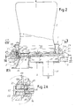
- Fig. 1 shows a side view of a coffee machine embodying the invention.
- the coffee machine 1 includes a housing 3 with a top ceiling 5 having a seat 7 in which a coffee beans container C can be introduced and engaged with the outlet opening of the container C oriented downwardly in order to dispense coffee beans to a coffee grinder 9 arranged inside the housing 3 of the machine 1.
- the grinder 9 grinds coffee beans dispensed from the coffee beans container to produce coffee powder dispensed to a brewing unit 11, also housed in the housing 3 of the coffee machine 1.
- the grinder 9 and the brewing unit 11 are known per se and will not be described in great detail herein.
- the machine 1 also includes a coffee dispensing spout 13 placed above a grid 15 on which a coffee cup CC or another suitable beverage container can be placed, such as a glass, a bowl or the like, in which the beverage dispensed by the dispensing spout 13 is collected.
- a coffee dispensing spout 13 placed above a grid 15 on which a coffee cup CC or another suitable beverage container can be placed, such as a glass, a bowl or the like, in which the beverage dispensed by the dispensing spout 13 is collected.
- the coffee beans container C can be a removable package, e.g. a disposable or re-usable package, which the user connects to the coffee machine and replaces once it is empty, i.e. when the coffee beans contained in the package has been entirely used.
- the interior of the coffee beans container C defines a first space or environment from which the coffee beans must be dispensed towards the coffee grinder 9.
- a channel 9A is arranged between the coffee beans container C and the coffee grinder 9, to convey and/or dose the coffee beans from the container C towards the coffee grinder 9.
- the channel 9A defines a second space or environment, which must be put into communication with the space or environment formed by the interior of the coffee beans containers C when the latter is attached on the top of the coffee machine 1.
- the coffee beans container C When the coffee beans container C is removed from the machine, for example in order to replace an empty container with a full container, or to replace a container containing one kind of coffee beans (e.g. regular coffee) with one containing a different kind of coffee beans (e.g. decaffeinated coffee, the aperture in the coffee machine, through which the coffee beans enter the channel 9A, must be closed. Underneath the seat 7 provided in the ceiling of the coffee machine housing 3 a device according to the invention is arranged, which provides for selectively opening and closing the entrance of the channel 9A.
- one kind of coffee beans e.g. regular coffee
- a different kind of coffee beans e.g. decaffeinated coffee
- Fig. 2 a section according to vertical plane of the device, designated 21 as a whole, is shown.
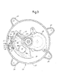
- Fig. 3 shows a cross section according to line III-III in Fig. 2 .
- the device 21 comprises a frame 23 which, in the embodiment shown herein, is approximately circular in shape.
- the frame 23 comprises feet 25 for connection to the stationary structure S of the coffee machine 1.
- Feet 25 are arranged around a circumferential cylindrical wall 27.
- the wall 27 surrounds a flat laminar diaphragm 29 having a first face 29A and a second face 29B.
- the diaphragm forms a partition wall which separates two spaces or environments formed by the coffee beans container C attached to the machine 1 and the channel 9A.
- Face 29A is oriented outwardly, towards the coffee beans container C when the latter is mounted on the machine 1, while face 29B is oriented toward the interior of the housing 3 of the coffee machine 1.
- the central diaphragm 29 has a central aperture 21 through which a dispensing rotor 33 projects.
- the rotor 33 acts upon a dispensing device, (not shown) contained in the container C in order to dispense the coffee beans contained therein in the channel 9A.
- the rotor 33 in drawn into rotation by a motor 35 mounted inside the housing 3 of the coffee machine 1.
- the diaphragm 29 is provided with a through aperture 37, through which coffee beans can be dispensed from the coffee beans container C in the channel 9A and to the coffee grinder 9.
- the aperture 37 must be open to allow dispensing of the coffee beans to the coffee grinder 9.
- the aperture 37 must be closed, in order to protect the component inside the machine, preventing dirt from penetrating inside the machine, and also for safety reasons.
- the device 21 comprises a shutter 39.
- the shutter 39 has a laminar shape, i.e. it is substantially be-dimensional and can be formed as a single piece of moulded plastic.
- the shutter 39 is provided with a port 41.
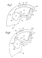
- the port 41 is aligned to the aperture 37 formed in the diaphragm 29 of the frame 23, see Fig.4 .
- the shutter 39 is rotated in such a position that the port 41 is out of alignment with respect the aperture 37, see Fig.6 .
- the two spaces namely the environment formed by the interior of container C and the environment formed by the channel 9A, are separated one from the other.
- the shutter 39 moves according to a circular trajectory coaxial to the container C, because the movement of the shutter 39 is controlled directly by the container C when the latter is connected or disconnected from the device 21 as it will be discussed later on.
- the shutter 39 could be differently activated or controlled.
- the shutter could be actuated by an external actuator or by other different devices.
- the movement of the shutter can be along a non-circular trajectory, e.g. a rectilinear trajectory.
- the shutter 39 can be provided with a control member through which an opening and closing movement is imparted to the shutter 39.
- the shutter 39 can be provided with a projection 45.
- the projection 45 includes an intermediate recess 47.
- the coffee beans container C is provided in turn with an appendage 49 (see Fig.2 ) suitable to engage in the recess 47 of the projection 45.
- the projection 45 and the recess 47 form a control member which is acted upon by the container C via the appendage 49, such that when the container C is introduced in the seat 7 and rotated to engage the seat 7, e.g.
- the rotation of the container C is transmitted to the shutter 39 (see also Fig.2A ).
- the container C is moved into the seat 7 such that the appendage 49 engages the recess 47 and once the coffee beans container is in the correct axial position, it is rotated around axis A-A and draws the shutter 39 from a closed position (with the port 41 out of alignment with respect to the aperture 37, Fig.6 ) in a open position (with a port 41 in alignment with the apertures 37, Fig.4 ).
- This angular movement of the coffee beans containers C also causes engagement of the coffee beans container C to the device 21 bay means of a bayonet-like connection or the like.
- the shutter 39 is arranged underneath the diaphragm 29 while the projection 45 projects through the diaphragm 29 and from the upper face 29A of the diaphragm 29.
- an arched slit 51 is provided in diaphragm 29.
- the arched slit 51 has the shape of a portion of a circumference with a center on axis A-A.
- the slit 51 forms a guide for the shutter 39.
- the shutter 39 can be further guided by a ring shaped projection 31A surrounding the central aperture 31 of the diaphragm 29.
- the shutter 39 is retained by a retention plate 52 attached to the lower surface 29B of the diaphragm 29.
- the device 21 comprises a latch 53 which selectively engages the shutter 39 to maintain it in the closed position when no coffee beans container C is attached to the machine 1.
- the latch 53 comprises a resilient tag 53A which engages the recess 47 of the projection 45 when the shutter 39 is in its closed position.
- the tag 53A is formed at the end of a resilient arm or a spring 55 which can be integrally formed as an extension of a block 57 retained between the frame 23 and a flange 59 constrained to frame 23 (see Figs 2 and 3 ).
- the appendage 49 ( Fig.2 ) provided on the container forces the tag 53A out of the recess 47 and engages the projection 45, such that rotation of the container C around its own axis will draw into rotation the projection 45 and thus the shutter 39.
- the upper surface of the tag 53A slanted such that the vertical force applied by the projection 49 of the container C will push the tag 53A radially outwardly out of engagement with the recess 47, such that the shutter 39 can be freely follow the rotation movement of the container C.
- the port 41 of the shutter 39 has an edge formed by two mechanical elements.
- a first portion 41A of the edge extending from a point 41B to a point 41C is formed by the main body of the shutter 39.
- a remaining portion 41D of the edge is formed by a laminar slider 61.
- the laminar slider 61 is resiliently yielding as will be disclosed here below.
- the slider 61 is arranged in a seat 63 formed as a window in the shutter 39. The seat 63 is placed adjacent the port 41. If the slider 61 is removed from the shutter 39 (see Figs. 9A, 9B , the window forming the seat 63 defines along with the port 41 a single empty space through the shutter 39.
- the slider 61 is slidingly engaged by opposite ridges 65A, 65B extending along two opposed curved edges of the seat 63.
- the slider 61 is arranged in a rest position in which the edge 41D formed on the slider 61 is placed adjacent the edge 41A formed on the main body of the shutter 39 such that the port 41 takes up its minimum dimension.
- This position is defined by abutments 41G (see in particular Figs. 9A, 9B ) formed on the main body of the shutter 39.
- the slider 61 is resiliently biased in this position by a spring 67.
- spring 67 is integrally formed of the same material forming the main body of shutter 39.
- the spring 67 projects from the edge of the seat 63 along which the ridge 65A is provided towards the opposite edge along which the ridge 65B is arranged.
- the plastic material forming the main body of the shutter 39 and the laminar spring 67 is sufficiently resilient such that an elastic force generated by the spring 67 biases the slider 61 in the rest position ( Figs. 3 , 4 , 6 , 7 ) where the port 41 has the minimum cross-section.
- a solid obstacle such as a coffee bean remains trapped between the edge of the aperture 37 formed in the diaphragm 29 and the portion 41D of the edge surrounding the port 41
- the slider 61 elastically yields allowing the shutter 39 to further move towards the closing position without the risk of projection 45 or the appendage 49 being broken.
- the resiliently biased slider 61 is blocked in a fixed position due to the coffee bean trapped in the aperture 37 and continued movement of the shutter 39 causes the laminar spring 37 to bias while the shutter 39 moves towards the closed position.
- Fig.5 where the container C has been removed to show the structure of the device 23 and the operation thereof
- a coffee bean B is trapped between aperture 37 and port 41.
- the spring 67 can bend to such an extent that the shutter 39 reaches its end closure position thus allowing the coffee beans container C to be removed.
- the elastic thrust exerted by the edge portion 41D against the coffee bean remained trapped between the latter and the edge of the aperture 37 is sufficient to expel the coffee bean from the aperture.
- the resiliently biased slider 61 snaps in its rest position under the thrust of the laminar spring 67.
- the resiliently biased slider 61 therefore defines a resiliently yielding edge or edge portion of the port 41 which allows the shutter 39 to reach its end closing position (where the port 41 is normally out of alignment with respect to the aperture 37) while the resiliently biased slider 61 remains temporarily in a retracted position having deformed the spring 67. This position is maintained until free space is gained for example by removing the coffee beans container C and allowing any obstacle, remained trapped between the edge of the aperture 37 and the edge 41D of the slider 61, to be removed. If the obstacle, for example a coffee bean, does not escape automatically after the coffee beans container has been removed, the user can push the obstacle out of the aperture into channel 9A, for example using a knife or a spoon.
Landscapes
- Engineering & Computer Science (AREA)
- Food Science & Technology (AREA)
- Mechanical Engineering (AREA)
- Apparatus For Making Beverages (AREA)
- Supply And Installment Of Electrical Components (AREA)
- Feeding Of Articles To Conveyors (AREA)
- Commercial Cooking Devices (AREA)
- Filling Or Emptying Of Bunkers, Hoppers, And Tanks (AREA)
Description
- The invention relates to a device for alternatively mutually separating or placing into communication two spaces or environments.
- In several kinds of devices and machines the need sometimes arises to selectively put two environments in communication or to separate one environment from the other, alternatively. For example, one space or environment can be formed by a product container, the product contained therein being selectively dispensed in a second space or environment, in which a device acting upon the product is arranged.
- In beverage producing machines, for example, containers for beverage ingredients in the form of bulk material, e.g. in granular or powder form, are provided. The ingredients contained in the containers must be selectively dispensed toward a brewing unit, a mixer or any other kind of apparatus, device, or component in which the beverage or a part thereof is prepared, for example using hot water flowing through a metered amount of beverage ingredient(s).
- In some circumstances two mutually adjoining spaces or environments must be separated from one another when no flow of product is required from one environment to the other, but they must be placed into communication if a product should flow from one space in the other.
- The invention provides for a device which efficiently and selectively places two mutually adjoining spaces or environments into communication or separates them one from the other depending upon at least one operative condition.
- In the context of the present description and of the appended claims a space or environment shall be understood as a volume which is entirely or partly surrounded by a boundary wall and separated from an adjoining such space or environment. For example an environment or space can be formed by the inner volume of a container, a conveying duct, a channel, a hopper or any other mechanical component which provides a volume which is at least partly surrounded by a closing wall.
- According to one embodiment of the invention a device is provided in which a special shutter can be selectively brought in a position in which an aperture placing the two spaces or environment into communication is open or alternatively in a position in which the aperture is closed. If bulk solid material flows from one space to the other passing through the aperture, the risk might arise that the material remains trapped between the aperture and the shutter. According to a preferred embodiment of the invention this is avoided by providing a port in the shutter which has at least one resiliently yielding edge. The yielding edge is moved with respect to the shutter against a resilient force if, during closure of the aperture between the first space and the second space, an obstacle remains trapped between the aperture and the shutter port.
- More specifically, according to one embodiment, a device is provided for separating a first space and a second space from one another, comprising: a partition wall, the first space and the second space being arranged on opposite sides of said partition wall; a through aperture in the partition wall connecting the first space and the second space and allowing a bulk material to move from the first space into the second space; a shutter, slidingly movable with respect to the partition wall, for selectively opening and closing said through aperture, the shutter having a port which can be selectively brought in an alignment position and in an out-of-alignment position with respect to said through aperture. The port has a resiliently yielding edge portion which is biased to a rest position and being capable of moving away from said rest position against an elastic biasing force if during closure of said shutter an obstacle obstructs the movement of the shutter with respect to the partition wall.
- In some embodiments the partition wall comprises a first guide for guiding the shutter with respect to the partition wall during opening and closing of the aperture.
- In some embodiments the shutter moves according to a circular trajectory with respect to said partition wall.
- According to preferred embodiments the resiliently yielding edge of the port of the shutter is formed by a resiliently biased slider, slidably engaged to the shutter. The shutter can comprise a second guide for the resiliently biased slider, to guide the latter with respect to the shutter. The above mentioned first and second guide can be substantially parallel to one another.
- In some embodiments the shutter comprises a seat in which the resiliently biased slider is slidingly housed, e.g. a seat in the form of a window formed in said shutter. The slider can be resiliently biased by a resilient member arranged in said seat, said resilient member biasing the slider towards a rest position corresponding to a minimum cross section of said port. The resilient member can be a separate member, arranged between the slider and the shutter. In preferred embodiments the resilient member is formed by an elastic projection integrally formed by the same material, e.g. plastic material, forming the shutter.
- The invention also concerns a coffee machine comprising a brewing unit, a coffee grinder and a device as above described, arranged above said grinder. The device separates a space or environment in which coffee beans are contained from a channel conveying the beans towards the grinder.
-
EP2364624 andAU2009202515 - According to a further aspect, the invention concerns a machine for delivering an edible product, such as a beverage or food, comprising a device as described here above.
- The above brief description sets forth features of the various embodiments of the present invention in order that the detailed description that follows may be better understood and in order that the present contributions to the art may be better appreciated. There are, of course, other features of the invention that will be described hereinafter and which will be set forth in the appended claims. In this respect, before explaining several embodiments of the invention in details, it is understood that the various embodiments of the invention are not limited in their application to the details of the construction and to the arrangements of the components set forth in the following description or illustrated in the drawings. The invention is capable of other embodiments and of being practiced and carried out in various ways. Also, it is to be understood that the phraseology and terminology employed herein are for the purpose of description and should not be regarded as limiting.
- As such, those skilled in the art will appreciate that the conception, upon which the disclosure is based, may readily be utilized as a basis for designing other structures, methods, and/or systems for carrying out the several purposes of the present invention. It is important, therefore, that the claims be regarded as including such equivalent constructions insofar as they do not depart from the spirit and scope of the present invention.
- A more complete appreciation of the disclosed embodiments of the invention and many of the attendant advantages thereof will be readily obtained as the same becomes better understood by reference to the following detailed description when considered in connection with the accompanying drawings, wherein:
-
Fig. 1 illustrates a side view of a coffee machine with a container of coffee beans and a coffee grinder; -
Fig. 2 illustrates a partial cross-section of the interface between the coffee beans container and the machine; -
Fig.2A illustrates an enlargement of detail marked IIA ofFig.2 ; -
Fig.3 illustrates a cross section according to line III-III ofFig.2 ; -
Fig. 4 illustrates a plan view according to line IV-IV inFig.2 , with the coffee beans container removed and the shutter in the open position; -
Fig.4A illustrates a perspective view of the frame including the shutter in the open position; -
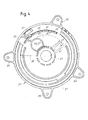
Fig.5 illustrates a plan view similar toFig.4 , with a coffee bean obstructing the closure of the shutter; -
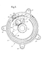
Fig.6 illustrates a plan view similar toFig.4 , with the shutter in the correct closed position; -
Figs 7 and 8 illustrate a top view of the shutter in two different positions; -
Figs 9A and 9B illustrate the two components of the shutter in a perspective view and disassembled condition. - The following detailed description of the exemplary embodiments refers to the accompanying drawings. The same reference numbers in different drawings identify the same or similar elements. Additionally, the drawings are not necessarily drawn to scale. Also, the following detailed description does not limit the invention. Instead, the scope of the invention is defined by the appended claims.
- Reference throughout the specification to "one embodiment" or "an embodiment" or "some embodiments" means that the particular feature, structure or characteristic described in connection with an embodiment is included in at least one embodiment of the subject matter disclosed. Thus, the appearance of the phrase "in one embodiment" or "in an embodiment" or "in some embodiments" in various places throughout the specification is not necessarily referring to the same embodiment(s). Further, the particular features, structures or characteristics may be combined in any suitable manner in one or more embodiments.
- The following description refers to an application of the invention in a coffee machine, but it should be understood that the invention can be embodied in other different kinds of beverage producing machines or also in different kinds of apparatus, machines or devices for handling edible products, where similar problems arise, as will be described in more detail here below, such as the risk of bulk material remaining trapped between an aperture, where through the bulk edible material is intended to flow, and a slider arranged to open and close said aperture.
-
Fig. 1 shows a side view of a coffee machine embodying the invention. The coffee machine 1 includes ahousing 3 with atop ceiling 5 having aseat 7 in which a coffee beans container C can be introduced and engaged with the outlet opening of the container C oriented downwardly in order to dispense coffee beans to a coffee grinder 9 arranged inside thehousing 3 of the machine 1. The grinder 9 grinds coffee beans dispensed from the coffee beans container to produce coffee powder dispensed to abrewing unit 11, also housed in thehousing 3 of the coffee machine 1. The grinder 9 and thebrewing unit 11 are known per se and will not be described in great detail herein. - The machine 1 also includes a
coffee dispensing spout 13 placed above agrid 15 on which a coffee cup CC or another suitable beverage container can be placed, such as a glass, a bowl or the like, in which the beverage dispensed by the dispensingspout 13 is collected. - In some embodiments the coffee beans container C can be a removable package, e.g. a disposable or re-usable package, which the user connects to the coffee machine and replaces once it is empty, i.e. when the coffee beans contained in the package has been entirely used. The interior of the coffee beans container C defines a first space or environment from which the coffee beans must be dispensed towards the coffee grinder 9. A channel 9A is arranged between the coffee beans container C and the coffee grinder 9, to convey and/or dose the coffee beans from the container C towards the coffee grinder 9. The channel 9A defines a second space or environment, which must be put into communication with the space or environment formed by the interior of the coffee beans containers C when the latter is attached on the top of the coffee machine 1.
- When the coffee beans container C is removed from the machine, for example in order to replace an empty container with a full container, or to replace a container containing one kind of coffee beans (e.g. regular coffee) with one containing a different kind of coffee beans (e.g. decaffeinated coffee, the aperture in the coffee machine, through which the coffee beans enter the channel 9A, must be closed. Underneath the
seat 7 provided in the ceiling of the coffee machine housing 3 a device according to the invention is arranged, which provides for selectively opening and closing the entrance of the channel 9A. - In
Fig. 2 a section according to vertical plane of the device, designated 21 as a whole, is shown.Fig. 3 shows a cross section according to line III-III inFig. 2 . - The
device 21 comprises aframe 23 which, in the embodiment shown herein, is approximately circular in shape. Theframe 23 comprisesfeet 25 for connection to the stationary structure S of the coffee machine 1.Feet 25 are arranged around a circumferentialcylindrical wall 27. Thewall 27 surrounds a flatlaminar diaphragm 29 having afirst face 29A and asecond face 29B. The diaphragm forms a partition wall which separates two spaces or environments formed by the coffee beans container C attached to the machine 1 and the channel 9A.Face 29A is oriented outwardly, towards the coffee beans container C when the latter is mounted on the machine 1, whileface 29B is oriented toward the interior of thehousing 3 of the coffee machine 1. - In some embodiments, as illustrated in the drawings, the
central diaphragm 29 has acentral aperture 21 through which a dispensingrotor 33 projects. Therotor 33 acts upon a dispensing device, (not shown) contained in the container C in order to dispense the coffee beans contained therein in the channel 9A. Therotor 33 in drawn into rotation by amotor 35 mounted inside thehousing 3 of the coffee machine 1. - The
diaphragm 29 is provided with a throughaperture 37, through which coffee beans can be dispensed from the coffee beans container C in the channel 9A and to the coffee grinder 9. When the coffee beans container C is attached to thedevice 21 theaperture 37 must be open to allow dispensing of the coffee beans to the coffee grinder 9. When the coffee container is removed, theaperture 37 must be closed, in order to protect the component inside the machine, preventing dirt from penetrating inside the machine, and also for safety reasons. - In order to selectively open and close the
aperture 37 thedevice 21 comprises ashutter 39. Theshutter 39 has a laminar shape, i.e. it is substantially be-dimensional and can be formed as a single piece of moulded plastic. Theshutter 39 is provided with aport 41. When theshutter 39 is in the open position theport 41 is aligned to theaperture 37 formed in thediaphragm 29 of theframe 23, seeFig.4 . In the closed position, i.e. when the container C is removed, theshutter 39 is rotated in such a position that theport 41 is out of alignment with respect theaperture 37, seeFig.6 . In this position the two spaces, namely the environment formed by the interior of container C and the environment formed by the channel 9A, are separated one from the other. - In the embodiment illustrated in the drawings the
shutter 39 moves according to a circular trajectory coaxial to the container C, because the movement of theshutter 39 is controlled directly by the container C when the latter is connected or disconnected from thedevice 21 as it will be discussed later on. In other embodiments, theshutter 39 could be differently activated or controlled. In some embodiments the shutter could be actuated by an external actuator or by other different devices. Depending upon the manner in which the shutter is controlled or acted upon to control opening and closing thereof, the movement of the shutter can be along a non-circular trajectory, e.g. a rectilinear trajectory. - The
shutter 39 can be provided with a control member through which an opening and closing movement is imparted to theshutter 39. For example, on the upper face of theshutter 39, i.e. the face oriented towards the container C, theshutter 39 can be provided with aprojection 45. In some embodiments theprojection 45 includes anintermediate recess 47. The coffee beans container C is provided in turn with an appendage 49 (seeFig.2 ) suitable to engage in therecess 47 of theprojection 45. Theprojection 45 and therecess 47 form a control member which is acted upon by the container C via theappendage 49, such that when the container C is introduced in theseat 7 and rotated to engage theseat 7, e.g. by means of a bayonet-type connection, the rotation of the container C is transmitted to the shutter 39 (see alsoFig.2A ). The container C is moved into theseat 7 such that theappendage 49 engages therecess 47 and once the coffee beans container is in the correct axial position, it is rotated around axis A-A and draws theshutter 39 from a closed position (with theport 41 out of alignment with respect to theaperture 37,Fig.6 ) in a open position (with aport 41 in alignment with theapertures 37,Fig.4 ). This angular movement of the coffee beans containers C also causes engagement of the coffee beans container C to thedevice 21 bay means of a bayonet-like connection or the like. - In some embodiments the
shutter 39 is arranged underneath thediaphragm 29 while theprojection 45 projects through thediaphragm 29 and from theupper face 29A of thediaphragm 29. To this end anarched slit 51 is provided indiaphragm 29. In order for theshutter 39 to move according to a circular trajectory coaxial to the coffee beans container C, thearched slit 51 has the shape of a portion of a circumference with a center on axis A-A. Theslit 51 forms a guide for theshutter 39. Theshutter 39 can be further guided by a ring shapedprojection 31A surrounding thecentral aperture 31 of thediaphragm 29. Theshutter 39 is retained by aretention plate 52 attached to thelower surface 29B of thediaphragm 29. - In some embodiments the
device 21 comprises alatch 53 which selectively engages theshutter 39 to maintain it in the closed position when no coffee beans container C is attached to the machine 1. In some embodiments thelatch 53 comprises aresilient tag 53A which engages therecess 47 of theprojection 45 when theshutter 39 is in its closed position. In some embodiments thetag 53A is formed at the end of a resilient arm or aspring 55 which can be integrally formed as an extension of ablock 57 retained between theframe 23 and aflange 59 constrained to frame 23 (seeFigs 2 and3 ). When the container C is connected to thedevice 21, the appendage 49 (Fig.2 ) provided on the container forces thetag 53A out of therecess 47 and engages theprojection 45, such that rotation of the container C around its own axis will draw into rotation theprojection 45 and thus theshutter 39. In some embodiments the upper surface of thetag 53A slanted such that the vertical force applied by theprojection 49 of the container C will push thetag 53A radially outwardly out of engagement with therecess 47, such that theshutter 39 can be freely follow the rotation movement of the container C. - As it can be seen in particular in
Figs 3 and7 , theport 41 of theshutter 39 has an edge formed by two mechanical elements. Afirst portion 41A of the edge extending from apoint 41B to apoint 41C is formed by the main body of theshutter 39. A remainingportion 41D of the edge is formed by alaminar slider 61. Thelaminar slider 61 is resiliently yielding as will be disclosed here below. For that purpose theslider 61 is arranged in aseat 63 formed as a window in theshutter 39. Theseat 63 is placed adjacent theport 41. If theslider 61 is removed from the shutter 39 (seeFigs. 9A, 9B , the window forming theseat 63 defines along with the port 41 a single empty space through theshutter 39. - The
slider 61 is slidingly engaged byopposite ridges seat 63. InFigs. 3 ,4 ,6 and7 theslider 61 is arranged in a rest position in which theedge 41D formed on theslider 61 is placed adjacent theedge 41A formed on the main body of theshutter 39 such that theport 41 takes up its minimum dimension. This position is defined by abutments 41G (see in particularFigs. 9A, 9B ) formed on the main body of theshutter 39. Theslider 61 is resiliently biased in this position by aspring 67. In some embodiments spring 67 is integrally formed of the same material forming the main body ofshutter 39. In some embodiments thespring 67 projects from the edge of theseat 63 along which theridge 65A is provided towards the opposite edge along which theridge 65B is arranged. The plastic material forming the main body of theshutter 39 and thelaminar spring 67 is sufficiently resilient such that an elastic force generated by thespring 67 biases theslider 61 in the rest position (Figs. 3 ,4 ,6 ,7 ) where theport 41 has the minimum cross-section. - If during the closure movement of the shutter 39 a solid obstacle, such as a coffee bean remains trapped between the edge of the
aperture 37 formed in thediaphragm 29 and theportion 41D of the edge surrounding theport 41, theslider 61 elastically yields allowing theshutter 39 to further move towards the closing position without the risk ofprojection 45 or theappendage 49 being broken. The resiliently biasedslider 61 is blocked in a fixed position due to the coffee bean trapped in theaperture 37 and continued movement of theshutter 39 causes thelaminar spring 37 to bias while theshutter 39 moves towards the closed position. InFig.5 (where the container C has been removed to show the structure of thedevice 23 and the operation thereof) a coffee bean B is trapped betweenaperture 37 andport 41. Thespring 67 can bend to such an extent that theshutter 39 reaches its end closure position thus allowing the coffee beans container C to be removed. When the coffee beans container C is removed, the elastic thrust exerted by theedge portion 41D against the coffee bean remained trapped between the latter and the edge of theaperture 37 is sufficient to expel the coffee bean from the aperture. Once the coffee bean is removed the resiliently biasedslider 61 snaps in its rest position under the thrust of thelaminar spring 67. - The resiliently biased
slider 61 therefore defines a resiliently yielding edge or edge portion of theport 41 which allows theshutter 39 to reach its end closing position (where theport 41 is normally out of alignment with respect to the aperture 37) while the resiliently biasedslider 61 remains temporarily in a retracted position having deformed thespring 67. This position is maintained until free space is gained for example by removing the coffee beans container C and allowing any obstacle, remained trapped between the edge of theaperture 37 and theedge 41D of theslider 61, to be removed. If the obstacle, for example a coffee bean, does not escape automatically after the coffee beans container has been removed, the user can push the obstacle out of the aperture into channel 9A, for example using a knife or a spoon. Even if the coffee bean B remains trapped theshutter 39 will not be damaged. A new coffee beans container C can be attached to the device and used to reopen theshutter 39. This will automatically cause the coffee bean B remained trapped in theaperture 37 to fall down by gravity in the underneath channel 9A. Integrity of thedevice 21 is maintained.
Claims (20)
- A device (21) for separating a first space (C) and a second space (9A) from one another, comprising:- a partition wall (29), the first space and the second space being arranged on opposite sides of said partition wall (29);- a through aperture (37) in the partition wall (29) connecting said first space and said second space and allowing a food bulk material to move from the first space (C) into the second space (9A);- a shutter (39), slidingly movable with respect to the partition wall (29), for selectively opening and closing said through aperture (37), the shutter having a port (41) which can be selectively brought in an alignment position and in an out-of-alignment position with respect to said through aperture (37);
characterized in that the port (41) has a resiliently yielding edge portion (41D), which is biased towards a rest position and is capable of moving away from said rest position against an elastic biasing force if during closure of said shutter an obstacle obstructs the movement of the shutter. - Device according to claim 1, wherein the partition wall (29) comprises a first guide (51) for guiding the shutter (39) with respect to said partition wall (29) during opening and closing of said aperture (37).
- Device according to claim 1 or 2, wherein said shutter (39) moves according to a circular trajectory with respect to said partition wall (29).
- Device according to claim 1 or 2 or 3, wherein the resiliently yielding edge (41D) of the port (41) of the shutter (39) is formed by a resiliently biased slider (61), slidably engaged to the shutter (39).
- Device according to claim 4, wherein the shutter (39) comprises a second guide (65A, 65B) for guiding the resiliently biased slider (61) with respect to said shutter (39).
- Device according to claims 2 and 5, wherein said first guide (51) and said second guide (65A, 65B) are substantially parallel to one another.
- Device according to one or more of claims 4 to 6, wherein said shutter (39) comprises a seat (63) in which the resiliently biased slider (61) is slidingly housed.
- Device according to claim 7, wherein said seat (63) is in the form of a window formed in said shutter (39).
- Device according to claim 7 or 8, comprising a resilient member (67) in said seat (63), said resilient member biasing the slider (61) towards a rest position corresponding to a minimum cross section of said port (41).
- Device according to claim 9, wherein the resilient member (67) is formed by an elastic projection integrally formed by the same material forming the shutter (39).
- Device according to claim 10, wherein said shutter (39) and said resilient member (67) are made of plastic material.
- Device according to one or more of the preceding claims, wherein said shutter (39) has a laminar shape.
- Device according to one or more of the preceding claims, comprisinga latch (53) for locking the shutter (39) with said port (41) in the out-of-alignment position with respect to the through aperture (37) of the partition wall (29).
- Device according to one or more of the preceding claims, wherein the shutter (39) is provided with a projection (45) for engagement with an operating member co-acting with said shutter (39) for moving the shutter respectively in an open position and a closed position.
- Device according to claim 13 and 14, wherein said latch (53) co-acts with said projection (45).
- Device according to claims 2 and 14 or 2 and 15, wherein the projection (45) extends through a slit (51) in the partition wall (29), said slit forming said first guide (51) for guiding the shutter (39) with respect to said partition wall (29) during opening and closing of said aperture (37).
- An edible product dispensing machine, comprising a container, containing a bulk material, and a device according to one or more of the preceding claims, wherein said container is arranged in or forms said first space.
- Machine according to claim 17, in the form of a coffee machine comprising a brewing unit (11) and a coffee grinder (9), said coffee grinder being arranged underneath said device, said bulk material comprising coffee beans, and said through aperture being intended for delivering coffee beans from said first space towards said coffee grinder.
- Machine according to claim 17 or 18, wherein said container (C) is engageable in a seat (7) above said partition wall (29) of said device (21), engagement of the container (C) with the frame causing movement of the shutter (39) to open said through aperture (37).
- Machine according to claims 18 and 19, wherein said first space is formed by said container and said second space is formed by a channel for feeding coffee beans from said container (C) to said coffee grinder (9).
Applications Claiming Priority (2)
| Application Number | Priority Date | Filing Date | Title |
|---|---|---|---|
| US201161549788P | 2011-10-21 | 2011-10-21 | |
| PCT/IB2012/055439 WO2013057625A2 (en) | 2011-10-21 | 2012-10-09 | A device for separating two spaces from one another |
Publications (2)
| Publication Number | Publication Date |
|---|---|
| EP2747617A2 EP2747617A2 (en) | 2014-07-02 |
| EP2747617B1 true EP2747617B1 (en) | 2015-09-23 |
Family
ID=47227985
Family Applications (1)
| Application Number | Title | Priority Date | Filing Date |
|---|---|---|---|
| EP12791555.1A Active EP2747617B1 (en) | 2011-10-21 | 2012-10-09 | A device for separating two spaces from one another |
Country Status (11)
| Country | Link |
|---|---|
| US (1) | US10327577B2 (en) |
| EP (1) | EP2747617B1 (en) |
| JP (1) | JP6006800B2 (en) |
| CN (1) | CN103874440B (en) |
| AU (1) | AU2012324492B2 (en) |
| BR (1) | BR112014009352B1 (en) |
| ES (1) | ES2553865T3 (en) |
| IN (1) | IN2014CN02648A (en) |
| MX (1) | MX343451B (en) |
| RU (1) | RU2596961C2 (en) |
| WO (1) | WO2013057625A2 (en) |
Families Citing this family (7)
| Publication number | Priority date | Publication date | Assignee | Title |
|---|---|---|---|---|
| CN103356083B (en) * | 2013-07-30 | 2015-12-09 | 宁波厨聚厨房科技有限公司 | A kind of bistrique D-M (Determiner-Measure) construction of mill |
| PL3361917T3 (en) * | 2015-10-12 | 2020-06-29 | Koninklijke Philips N.V. | Grinding unit and coffee machine |
| ITUA20161566A1 (en) * | 2016-03-11 | 2017-09-11 | De Longhi Appliances Srl | COFFEE MACHINE INCORPORATING A MILL |
| GB201614527D0 (en) * | 2016-08-25 | 2016-10-12 | Ishida Europe Ltd | An apparatus and method for dispensing flavouring |
| IT201600096953A1 (en) * | 2016-09-27 | 2018-03-27 | Illycaffe Spa | APPARATUS AND METHOD TO OBTAIN CUSTOMIZED COFFEE MIXTURES |
| EP3801149A1 (en) | 2018-05-28 | 2021-04-14 | Société des Produits Nestlé S.A. | Dispenser of bulk material |
| AU2019297207A1 (en) * | 2018-07-06 | 2021-01-28 | Newell Australia Pty Ltd | Foodstuff processing system |
Family Cites Families (29)
| Publication number | Priority date | Publication date | Assignee | Title |
|---|---|---|---|---|
| US94116A (en) * | 1869-08-24 | Improvement in the construction of houses | ||
| US454298A (en) * | 1891-06-16 | William shempp | ||
| US1725942A (en) * | 1927-01-10 | 1929-08-27 | Stimpson | Shut-off mechanism for coffee-mill hoppers |
| US3129845A (en) * | 1961-03-17 | 1964-04-21 | Musser C Walton | Timing device and dispenser |
| US4053087A (en) * | 1975-11-28 | 1977-10-11 | General Foods Limited | Dispenser for granular material |
| JPS5825978Y2 (en) * | 1980-11-20 | 1983-06-04 | 松下電器産業株式会社 | Tabletop condiment “Hi” device |
| JPH0728827B2 (en) * | 1990-02-02 | 1995-04-05 | 上田 千歌子 | Coffee maker |
| DE4436092C1 (en) * | 1994-10-10 | 1995-11-30 | Braun Ag | Food processing and mixing unit, protected against food ingress, |
| NL1001989C2 (en) | 1995-12-22 | 1997-06-24 | Gerrit Jan Van Den Top | Vending machine. |
| WO1997041763A1 (en) * | 1996-05-03 | 1997-11-13 | Bianco James S | Coffee bean blending apparatus and method |
| US5947171A (en) * | 1997-01-30 | 1999-09-07 | American Cyanamid Company | Valve assembly for use with containers in a closed application system |
| US7264186B2 (en) | 1999-04-30 | 2007-09-04 | Food Equipment Technologies Company, Inc. | Food ingredient grinder with tool-less removable ingredient hopper and method |
| US6626085B1 (en) * | 1999-04-30 | 2003-09-30 | Food Equipment Technologies Company, Inc. | Food ingredients grinder removable ingredient hopper and method |
| US6364155B1 (en) * | 2000-04-07 | 2002-04-02 | Owens-Illinois Closure Inc. | Child resistant pill dispensing package |
| US6698624B2 (en) * | 2001-04-04 | 2004-03-02 | Nestec S.A. | Device for dispensing a flowable powder substance |
| ITMI20020973A1 (en) * | 2002-05-09 | 2003-11-10 | Rheavendors S P A | MACHINE FOR THE PREPARATION OF BEVERAGES |
| CN2587306Y (en) * | 2002-12-26 | 2003-11-26 | 张明亮 | Check stopper for preparing direct drinking water |
| GB2397500B (en) | 2003-01-24 | 2005-03-23 | Kraft Foods R & D Inc | Cartridge for the preparation of beverages |
| WO2005021914A1 (en) * | 2003-09-03 | 2005-03-10 | Dpnkd Holdings Inc. | Automatic portable door operating system |
| JP2005092396A (en) * | 2003-09-16 | 2005-04-07 | Matsushita Electric Ind Co Ltd | Powder ingredient supply device for cup type vending machine |
| SE530085C2 (en) * | 2006-01-30 | 2008-02-26 | Timothy Richard Vinnicombe | Microwave Oven |
| FR2902303B1 (en) * | 2006-06-15 | 2013-07-12 | Seb Sa | PULVERULENT PRODUCT DISPENSER WITH REMOVABLE TANK |
| AU2009202515A1 (en) * | 2008-06-23 | 2010-01-14 | Sunbeam Corporation Limited | Coffee-bean container for coffee grinder |
| ITFI20080121A1 (en) * | 2008-06-30 | 2010-01-01 | Saeco Ipr Ltd | "SEPARATION DEVICE BETWEEN DIFFERENT ENVIRONMENTS AND DOSAGE OF A FOOD PRODUCT AND MACHINE INCORPORATING THE DEVICE" |
| WO2010032271A1 (en) * | 2008-09-18 | 2010-03-25 | Saeco Ipr Limited | Infusion device for coffee machines and the like |
| US8307513B1 (en) * | 2009-01-28 | 2012-11-13 | PinStop USA, LLC | Door hinge with integrated preset stops |
| CA2950519C (en) * | 2009-02-17 | 2019-07-16 | Koninklijke Douwe Egberts B.V. | Coffee bean packaging cartridge and coffee beverage system including same |
| WO2011102715A2 (en) * | 2010-02-17 | 2011-08-25 | Sara Lee/De N.V. | Coffee beverage system, coffee brewing apparatus, coffee bean packaging cartridge and method for preparing a coffee beverage |
| JP2011167396A (en) * | 2010-02-19 | 2011-09-01 | Sanyo Electric Co Ltd | Beverage making apparatus |
-
2012
- 2012-10-09 RU RU2014120162/12A patent/RU2596961C2/en active
- 2012-10-09 US US14/352,847 patent/US10327577B2/en active Active
- 2012-10-09 JP JP2014536364A patent/JP6006800B2/en not_active Expired - Fee Related
- 2012-10-09 ES ES12791555.1T patent/ES2553865T3/en active Active
- 2012-10-09 MX MX2014004586A patent/MX343451B/en active IP Right Grant
- 2012-10-09 BR BR112014009352-0A patent/BR112014009352B1/en active IP Right Grant
- 2012-10-09 IN IN2648CHN2014 patent/IN2014CN02648A/en unknown
- 2012-10-09 EP EP12791555.1A patent/EP2747617B1/en active Active
- 2012-10-09 AU AU2012324492A patent/AU2012324492B2/en active Active
- 2012-10-09 CN CN201280051171.6A patent/CN103874440B/en active Active
- 2012-10-09 WO PCT/IB2012/055439 patent/WO2013057625A2/en active Application Filing
Also Published As
| Publication number | Publication date |
|---|---|
| AU2012324492B2 (en) | 2017-02-23 |
| RU2596961C2 (en) | 2016-09-10 |
| JP6006800B2 (en) | 2016-10-12 |
| MX2014004586A (en) | 2014-06-23 |
| IN2014CN02648A (en) | 2015-08-07 |
| AU2012324492A1 (en) | 2014-06-12 |
| EP2747617A2 (en) | 2014-07-02 |
| BR112014009352A2 (en) | 2017-04-18 |
| CN103874440A (en) | 2014-06-18 |
| RU2014120162A (en) | 2015-11-27 |
| WO2013057625A2 (en) | 2013-04-25 |
| JP2014530700A (en) | 2014-11-20 |
| BR112014009352B1 (en) | 2020-10-13 |
| ES2553865T3 (en) | 2015-12-14 |
| MX343451B (en) | 2016-11-07 |
| US10327577B2 (en) | 2019-06-25 |
| WO2013057625A3 (en) | 2013-08-01 |
| CN103874440B (en) | 2017-06-30 |
| US20140251149A1 (en) | 2014-09-11 |
Similar Documents
| Publication | Publication Date | Title |
|---|---|---|
| EP2747617B1 (en) | A device for separating two spaces from one another | |
| US11623222B2 (en) | Separation apparatus, grinding apparatus and beverage producing apparatus | |
| EP2760320B1 (en) | Apparatus, systems, and methods for grinding a material | |
| US10595665B2 (en) | Extracting method and extracting apparatus | |
| RU2556513C2 (en) | Coffee beams package cartridge and coffee brewing system including such cartridge | |
| JP2014520619A (en) | Ingredient holder for beverages with a lock and pivoting to close | |
| CA2842936A1 (en) | Beverage dispenser with improved refilling operation | |
| US20190038064A1 (en) | Extracting apparatus and extracting method | |
| EP2682029B1 (en) | Beverage preparation machine with movable mixing chamber | |
| JP6564400B2 (en) | Beverage preparation machine with refillable multi-use storage container | |
| EP2767198B1 (en) | A filter holder for an espresso coffee machine | |
| US11083326B2 (en) | Ground coffee dispenser for a coffee machine provided with a turbine with curved blades | |
| CN109195902B (en) | Machine and method for preparing a beverage from a cartridge of beverage concentrate |
Legal Events
| Date | Code | Title | Description |
|---|---|---|---|
| PUAI | Public reference made under article 153(3) epc to a published international application that has entered the european phase |
Free format text: ORIGINAL CODE: 0009012 |
|
| 17P | Request for examination filed |
Effective date: 20140324 |
|
| AK | Designated contracting states |
Kind code of ref document: A2 Designated state(s): AL AT BE BG CH CY CZ DE DK EE ES FI FR GB GR HR HU IE IS IT LI LT LU LV MC MK MT NL NO PL PT RO RS SE SI SK SM TR |
|
| DAX | Request for extension of the european patent (deleted) | ||
| GRAP | Despatch of communication of intention to grant a patent |
Free format text: ORIGINAL CODE: EPIDOSNIGR1 |
|
| INTG | Intention to grant announced |
Effective date: 20150428 |
|
| GRAS | Grant fee paid |
Free format text: ORIGINAL CODE: EPIDOSNIGR3 |
|
| GRAA | (expected) grant |
Free format text: ORIGINAL CODE: 0009210 |
|
| AK | Designated contracting states |
Kind code of ref document: B1 Designated state(s): AL AT BE BG CH CY CZ DE DK EE ES FI FR GB GR HR HU IE IS IT LI LT LU LV MC MK MT NL NO PL PT RO RS SE SI SK SM TR |
|
| REG | Reference to a national code |
Ref country code: GB Ref legal event code: FG4D |
|
| REG | Reference to a national code |
Ref country code: CH Ref legal event code: EP |
|
| REG | Reference to a national code |
Ref country code: AT Ref legal event code: REF Ref document number: 750734 Country of ref document: AT Kind code of ref document: T Effective date: 20151015 |
|
| REG | Reference to a national code |
Ref country code: IE Ref legal event code: FG4D |
|
| REG | Reference to a national code |
Ref country code: FR Ref legal event code: PLFP Year of fee payment: 4 |
|
| REG | Reference to a national code |
Ref country code: DE Ref legal event code: R096 Ref document number: 602012011008 Country of ref document: DE |
|
| REG | Reference to a national code |
Ref country code: ES Ref legal event code: FG2A Ref document number: 2553865 Country of ref document: ES Kind code of ref document: T3 Effective date: 20151214 |
|
| REG | Reference to a national code |
Ref country code: NL Ref legal event code: MP Effective date: 20150923 |
|
| PG25 | Lapsed in a contracting state [announced via postgrant information from national office to epo] |
Ref country code: GR Free format text: LAPSE BECAUSE OF FAILURE TO SUBMIT A TRANSLATION OF THE DESCRIPTION OR TO PAY THE FEE WITHIN THE PRESCRIBED TIME-LIMIT Effective date: 20151224 Ref country code: LT Free format text: LAPSE BECAUSE OF FAILURE TO SUBMIT A TRANSLATION OF THE DESCRIPTION OR TO PAY THE FEE WITHIN THE PRESCRIBED TIME-LIMIT Effective date: 20150923 Ref country code: FI Free format text: LAPSE BECAUSE OF FAILURE TO SUBMIT A TRANSLATION OF THE DESCRIPTION OR TO PAY THE FEE WITHIN THE PRESCRIBED TIME-LIMIT Effective date: 20150923 Ref country code: NO Free format text: LAPSE BECAUSE OF FAILURE TO SUBMIT A TRANSLATION OF THE DESCRIPTION OR TO PAY THE FEE WITHIN THE PRESCRIBED TIME-LIMIT Effective date: 20151223 Ref country code: LV Free format text: LAPSE BECAUSE OF FAILURE TO SUBMIT A TRANSLATION OF THE DESCRIPTION OR TO PAY THE FEE WITHIN THE PRESCRIBED TIME-LIMIT Effective date: 20150923 |
|
| REG | Reference to a national code |
Ref country code: LT Ref legal event code: MG4D |
|
| REG | Reference to a national code |
Ref country code: AT Ref legal event code: MK05 Ref document number: 750734 Country of ref document: AT Kind code of ref document: T Effective date: 20150923 |
|
| PG25 | Lapsed in a contracting state [announced via postgrant information from national office to epo] |
Ref country code: HR Free format text: LAPSE BECAUSE OF FAILURE TO SUBMIT A TRANSLATION OF THE DESCRIPTION OR TO PAY THE FEE WITHIN THE PRESCRIBED TIME-LIMIT Effective date: 20150923 Ref country code: RS Free format text: LAPSE BECAUSE OF FAILURE TO SUBMIT A TRANSLATION OF THE DESCRIPTION OR TO PAY THE FEE WITHIN THE PRESCRIBED TIME-LIMIT Effective date: 20150923 Ref country code: SE Free format text: LAPSE BECAUSE OF FAILURE TO SUBMIT A TRANSLATION OF THE DESCRIPTION OR TO PAY THE FEE WITHIN THE PRESCRIBED TIME-LIMIT Effective date: 20150923 |
|
| PG25 | Lapsed in a contracting state [announced via postgrant information from national office to epo] |
Ref country code: NL Free format text: LAPSE BECAUSE OF FAILURE TO SUBMIT A TRANSLATION OF THE DESCRIPTION OR TO PAY THE FEE WITHIN THE PRESCRIBED TIME-LIMIT Effective date: 20150923 |
|
| PG25 | Lapsed in a contracting state [announced via postgrant information from national office to epo] |
Ref country code: CZ Free format text: LAPSE BECAUSE OF FAILURE TO SUBMIT A TRANSLATION OF THE DESCRIPTION OR TO PAY THE FEE WITHIN THE PRESCRIBED TIME-LIMIT Effective date: 20150923 Ref country code: IS Free format text: LAPSE BECAUSE OF FAILURE TO SUBMIT A TRANSLATION OF THE DESCRIPTION OR TO PAY THE FEE WITHIN THE PRESCRIBED TIME-LIMIT Effective date: 20160123 Ref country code: EE Free format text: LAPSE BECAUSE OF FAILURE TO SUBMIT A TRANSLATION OF THE DESCRIPTION OR TO PAY THE FEE WITHIN THE PRESCRIBED TIME-LIMIT Effective date: 20150923 Ref country code: SK Free format text: LAPSE BECAUSE OF FAILURE TO SUBMIT A TRANSLATION OF THE DESCRIPTION OR TO PAY THE FEE WITHIN THE PRESCRIBED TIME-LIMIT Effective date: 20150923 |
|
| PG25 | Lapsed in a contracting state [announced via postgrant information from national office to epo] |
Ref country code: RO Free format text: LAPSE BECAUSE OF FAILURE TO SUBMIT A TRANSLATION OF THE DESCRIPTION OR TO PAY THE FEE WITHIN THE PRESCRIBED TIME-LIMIT Effective date: 20150923 Ref country code: PL Free format text: LAPSE BECAUSE OF FAILURE TO SUBMIT A TRANSLATION OF THE DESCRIPTION OR TO PAY THE FEE WITHIN THE PRESCRIBED TIME-LIMIT Effective date: 20150923 Ref country code: AT Free format text: LAPSE BECAUSE OF FAILURE TO SUBMIT A TRANSLATION OF THE DESCRIPTION OR TO PAY THE FEE WITHIN THE PRESCRIBED TIME-LIMIT Effective date: 20150923 Ref country code: PT Free format text: LAPSE BECAUSE OF FAILURE TO SUBMIT A TRANSLATION OF THE DESCRIPTION OR TO PAY THE FEE WITHIN THE PRESCRIBED TIME-LIMIT Effective date: 20160125 |
|
| REG | Reference to a national code |
Ref country code: CH Ref legal event code: PL |
|
| REG | Reference to a national code |
Ref country code: DE Ref legal event code: R097 Ref document number: 602012011008 Country of ref document: DE |
|
| PG25 | Lapsed in a contracting state [announced via postgrant information from national office to epo] |
Ref country code: MC Free format text: LAPSE BECAUSE OF FAILURE TO SUBMIT A TRANSLATION OF THE DESCRIPTION OR TO PAY THE FEE WITHIN THE PRESCRIBED TIME-LIMIT Effective date: 20150923 |
|
| REG | Reference to a national code |
Ref country code: IE Ref legal event code: MM4A |
|
| PG25 | Lapsed in a contracting state [announced via postgrant information from national office to epo] |
Ref country code: LI Free format text: LAPSE BECAUSE OF NON-PAYMENT OF DUE FEES Effective date: 20151031 Ref country code: CH Free format text: LAPSE BECAUSE OF NON-PAYMENT OF DUE FEES Effective date: 20151031 |
|
| PLBE | No opposition filed within time limit |
Free format text: ORIGINAL CODE: 0009261 |
|
| STAA | Information on the status of an ep patent application or granted ep patent |
Free format text: STATUS: NO OPPOSITION FILED WITHIN TIME LIMIT |
|
| 26N | No opposition filed |
Effective date: 20160624 |
|
| PG25 | Lapsed in a contracting state [announced via postgrant information from national office to epo] |
Ref country code: DK Free format text: LAPSE BECAUSE OF FAILURE TO SUBMIT A TRANSLATION OF THE DESCRIPTION OR TO PAY THE FEE WITHIN THE PRESCRIBED TIME-LIMIT Effective date: 20150923 |
|
| REG | Reference to a national code |
Ref country code: FR Ref legal event code: PLFP Year of fee payment: 5 |
|
| PG25 | Lapsed in a contracting state [announced via postgrant information from national office to epo] |
Ref country code: IE Free format text: LAPSE BECAUSE OF NON-PAYMENT OF DUE FEES Effective date: 20151009 |
|
| PG25 | Lapsed in a contracting state [announced via postgrant information from national office to epo] |
Ref country code: SI Free format text: LAPSE BECAUSE OF FAILURE TO SUBMIT A TRANSLATION OF THE DESCRIPTION OR TO PAY THE FEE WITHIN THE PRESCRIBED TIME-LIMIT Effective date: 20150923 |
|
| PG25 | Lapsed in a contracting state [announced via postgrant information from national office to epo] |
Ref country code: BE Free format text: LAPSE BECAUSE OF FAILURE TO SUBMIT A TRANSLATION OF THE DESCRIPTION OR TO PAY THE FEE WITHIN THE PRESCRIBED TIME-LIMIT Effective date: 20150923 |
|
| PG25 | Lapsed in a contracting state [announced via postgrant information from national office to epo] |
Ref country code: SM Free format text: LAPSE BECAUSE OF FAILURE TO SUBMIT A TRANSLATION OF THE DESCRIPTION OR TO PAY THE FEE WITHIN THE PRESCRIBED TIME-LIMIT Effective date: 20150923 Ref country code: HU Free format text: LAPSE BECAUSE OF FAILURE TO SUBMIT A TRANSLATION OF THE DESCRIPTION OR TO PAY THE FEE WITHIN THE PRESCRIBED TIME-LIMIT; INVALID AB INITIO Effective date: 20121009 Ref country code: BG Free format text: LAPSE BECAUSE OF FAILURE TO SUBMIT A TRANSLATION OF THE DESCRIPTION OR TO PAY THE FEE WITHIN THE PRESCRIBED TIME-LIMIT Effective date: 20150923 |
|
| PG25 | Lapsed in a contracting state [announced via postgrant information from national office to epo] |
Ref country code: CY Free format text: LAPSE BECAUSE OF FAILURE TO SUBMIT A TRANSLATION OF THE DESCRIPTION OR TO PAY THE FEE WITHIN THE PRESCRIBED TIME-LIMIT Effective date: 20150923 |
|
| PG25 | Lapsed in a contracting state [announced via postgrant information from national office to epo] |
Ref country code: MT Free format text: LAPSE BECAUSE OF FAILURE TO SUBMIT A TRANSLATION OF THE DESCRIPTION OR TO PAY THE FEE WITHIN THE PRESCRIBED TIME-LIMIT Effective date: 20150923 |
|
| REG | Reference to a national code |
Ref country code: FR Ref legal event code: PLFP Year of fee payment: 6 |
|
| PG25 | Lapsed in a contracting state [announced via postgrant information from national office to epo] |
Ref country code: LU Free format text: LAPSE BECAUSE OF NON-PAYMENT OF DUE FEES Effective date: 20151009 |
|
| PG25 | Lapsed in a contracting state [announced via postgrant information from national office to epo] |
Ref country code: MK Free format text: LAPSE BECAUSE OF FAILURE TO SUBMIT A TRANSLATION OF THE DESCRIPTION OR TO PAY THE FEE WITHIN THE PRESCRIBED TIME-LIMIT Effective date: 20150923 |
|
| REG | Reference to a national code |
Ref country code: FR Ref legal event code: PLFP Year of fee payment: 7 |
|
| PG25 | Lapsed in a contracting state [announced via postgrant information from national office to epo] |
Ref country code: AL Free format text: LAPSE BECAUSE OF FAILURE TO SUBMIT A TRANSLATION OF THE DESCRIPTION OR TO PAY THE FEE WITHIN THE PRESCRIBED TIME-LIMIT Effective date: 20150923 |
|
| PGFP | Annual fee paid to national office [announced via postgrant information from national office to epo] |
Ref country code: TR Payment date: 20190927 Year of fee payment: 8 |
|
| PGFP | Annual fee paid to national office [announced via postgrant information from national office to epo] |
Ref country code: GB Payment date: 20191029 Year of fee payment: 8 |
|
| GBPC | Gb: european patent ceased through non-payment of renewal fee |
Effective date: 20201009 |
|
| PG25 | Lapsed in a contracting state [announced via postgrant information from national office to epo] |
Ref country code: GB Free format text: LAPSE BECAUSE OF NON-PAYMENT OF DUE FEES Effective date: 20201009 |
|
| PG25 | Lapsed in a contracting state [announced via postgrant information from national office to epo] |
Ref country code: TR Free format text: LAPSE BECAUSE OF NON-PAYMENT OF DUE FEES Effective date: 20201009 |
|
| P01 | Opt-out of the competence of the unified patent court (upc) registered |
Effective date: 20230626 |
|
| REG | Reference to a national code |
Ref country code: DE Ref legal event code: R081 Ref document number: 602012011008 Country of ref document: DE Owner name: VERSUNI HOLDING B.V., NL Free format text: FORMER OWNERS: KONINKLIJKE DOUWE EGBERTS B.V., UTRECHT, NL; KONINKLIJKE PHILIPS N.V., EINDHOVEN, NL Ref country code: DE Ref legal event code: R081 Ref document number: 602012011008 Country of ref document: DE Owner name: KONINKLIJKE DOUWE EGBERTS B.V., NL Free format text: FORMER OWNERS: KONINKLIJKE DOUWE EGBERTS B.V., UTRECHT, NL; KONINKLIJKE PHILIPS N.V., EINDHOVEN, NL |
|
| PGFP | Annual fee paid to national office [announced via postgrant information from national office to epo] |
Ref country code: ES Payment date: 20231110 Year of fee payment: 12 |
|
| PGFP | Annual fee paid to national office [announced via postgrant information from national office to epo] |
Ref country code: IT Payment date: 20231024 Year of fee payment: 12 Ref country code: FR Payment date: 20231026 Year of fee payment: 12 Ref country code: DE Payment date: 20231027 Year of fee payment: 12 |