EP2747533B1 - Electronic switching cabinet with cooling - Google Patents
Electronic switching cabinet with cooling Download PDFInfo
- Publication number
- EP2747533B1 EP2747533B1 EP12198984.2A EP12198984A EP2747533B1 EP 2747533 B1 EP2747533 B1 EP 2747533B1 EP 12198984 A EP12198984 A EP 12198984A EP 2747533 B1 EP2747533 B1 EP 2747533B1
- Authority
- EP
- European Patent Office
- Prior art keywords
- modules
- air
- horizontal
- duct
- openings
- Prior art date
- Legal status (The legal status is an assumption and is not a legal conclusion. Google has not performed a legal analysis and makes no representation as to the accuracy of the status listed.)
- Not-in-force
Links
- 238000001816 cooling Methods 0.000 title claims description 42
- 230000008878 coupling Effects 0.000 claims description 19
- 238000010168 coupling process Methods 0.000 claims description 19
- 238000005859 coupling reaction Methods 0.000 claims description 19
- 230000000712 assembly Effects 0.000 claims description 10
- 238000000429 assembly Methods 0.000 claims description 10
- 238000005192 partition Methods 0.000 description 6
- 238000010438 heat treatment Methods 0.000 description 5
- 230000017525 heat dissipation Effects 0.000 description 2
- 230000020169 heat generation Effects 0.000 description 2
- 238000009434 installation Methods 0.000 description 2
- 238000009423 ventilation Methods 0.000 description 2
- 238000010792 warming Methods 0.000 description 2
- 241000233805 Phoenix Species 0.000 description 1
- 230000015572 biosynthetic process Effects 0.000 description 1
- 238000005516 engineering process Methods 0.000 description 1
- 238000011084 recovery Methods 0.000 description 1
- 238000007789 sealing Methods 0.000 description 1
- 239000004065 semiconductor Substances 0.000 description 1
Images


Classifications
-
- G—PHYSICS
- G08—SIGNALLING
- G08B—SIGNALLING OR CALLING SYSTEMS; ORDER TELEGRAPHS; ALARM SYSTEMS
- G08B17/00—Fire alarms; Alarms responsive to explosion
-
- H—ELECTRICITY
- H05—ELECTRIC TECHNIQUES NOT OTHERWISE PROVIDED FOR
- H05K—PRINTED CIRCUITS; CASINGS OR CONSTRUCTIONAL DETAILS OF ELECTRIC APPARATUS; MANUFACTURE OF ASSEMBLAGES OF ELECTRICAL COMPONENTS
- H05K7/00—Constructional details common to different types of electric apparatus
- H05K7/20—Modifications to facilitate cooling, ventilating, or heating
- H05K7/20009—Modifications to facilitate cooling, ventilating, or heating using a gaseous coolant in electronic enclosures
-
- H—ELECTRICITY
- H05—ELECTRIC TECHNIQUES NOT OTHERWISE PROVIDED FOR
- H05K—PRINTED CIRCUITS; CASINGS OR CONSTRUCTIONAL DETAILS OF ELECTRIC APPARATUS; MANUFACTURE OF ASSEMBLAGES OF ELECTRICAL COMPONENTS
- H05K7/00—Constructional details common to different types of electric apparatus
- H05K7/14—Mounting supporting structure in casing or on frame or rack
- H05K7/1462—Mounting supporting structure in casing or on frame or rack for programmable logic controllers [PLC] for automation or industrial process control
- H05K7/1467—PLC mounted in a cabinet or chassis
-
- H—ELECTRICITY
- H05—ELECTRIC TECHNIQUES NOT OTHERWISE PROVIDED FOR
- H05K—PRINTED CIRCUITS; CASINGS OR CONSTRUCTIONAL DETAILS OF ELECTRIC APPARATUS; MANUFACTURE OF ASSEMBLAGES OF ELECTRICAL COMPONENTS
- H05K7/00—Constructional details common to different types of electric apparatus
- H05K7/20—Modifications to facilitate cooling, ventilating, or heating
- H05K7/20536—Modifications to facilitate cooling, ventilating, or heating for racks or cabinets of standardised dimensions, e.g. electronic racks for aircraft or telecommunication equipment
- H05K7/20554—Forced ventilation of a gaseous coolant
- H05K7/20572—Forced ventilation of a gaseous coolant within cabinets for removing heat from sub-racks, e.g. plenum
Landscapes
- Engineering & Computer Science (AREA)
- Microelectronics & Electronic Packaging (AREA)
- Physics & Mathematics (AREA)
- Thermal Sciences (AREA)
- Automation & Control Theory (AREA)
- Aviation & Aerospace Engineering (AREA)
- Business, Economics & Management (AREA)
- Emergency Management (AREA)
- General Physics & Mathematics (AREA)
- Cooling Or The Like Of Electrical Apparatus (AREA)
Description
Die Erfindung betrifft einen elektronischen Schaltschrank für eine Brandmelder- und/oder Löschsteuerzentrale entsprechend dem Oberbegriff des ersten Patentanspruches.The invention relates to an electronic control cabinet for a fire alarm and / or extinguishing control center according to the preamble of the first claim.
Der erfindungsgemäße Schaltschrank ist überall dort einsetzbar, wo eine Brandmelder-und/oder Löschsteuerzentrale vorhanden ist und die im elektronischen Schaltschrank befindlichen Module Wärme erzeugen, so dass sie gekühlt werden müssen.The control cabinet according to the invention can be used anywhere where a fire alarm and / or extinguishing control center is present and the modules located in the electronic control cabinet generate heat so that they must be cooled.
Elektronische Schaltschränke für Brandmelder- und/oder Löschsteuerzentralen sind allgemein bekannt und bestehen aus dem Gehäuse mit einer Befestigungsmöglichkeit für Module, in denen elektronische Baugruppen angeordnet sind, wobei die Module untereinander und mit einem Außenbereich mit externen Komponenten in Verbindung stehen. Module dieser Art bestehen aus einem Gehäuse und den im Inneren angeordneten elektronischen Baugruppen.Electronic control cabinets for fire alarm and / or extinguishing control panels are well known and consist of the housing with a mounting option for modules in which electronic modules are arranged, the modules are interconnected and with an outdoor area with external components in combination. Modules of this type consist of a housing and the electronic assemblies arranged inside.
Die in den Modulen angeordneten elektronischen Baugruppen können Schaltungsteile oder Halbleiterbauelemente enthalten, welche eine Wärmeverlustleistung erzeugen, die abgeführt werden muss. Um die elektronischen Baugruppen und deren Bauelemente im spezifizierten Temperaturbereich zu betreiben, kann es erforderlich sein, die Module, d. h. deren elektronische Baugruppen, zusätzlich zur Kühlung durch freie Konvektion, wie sie im bekannten Stand der Technik erfolgt, zu kühlen.The electronic components arranged in the modules can contain circuit parts or semiconductor components which generate a heat dissipation power that has to be dissipated. In order to operate the electronic assemblies and their components in the specified temperature range, it may be necessary to use the modules, i. H. their electronic assemblies, in addition to cooling by free convection, as is done in the prior art, to cool.
Eine freie Konvektion kann aber durch unterhalb und oberhalb der Module installierten Einbauten wie Kabelkanäle behindert bzw. unterbunden werden. Um die Leistungsfähigkeit einzelner Module zu erhöhen und ein höhere Wärmeverlustleistung lokal abzuführen ist die Nutzung der freien Konvektion nicht ausreichend.However, free convection can be hindered or prevented by installations installed below and above the modules, such as cable ducts. In order to increase the efficiency of individual modules and dissipate a higher heat dissipation capacity locally, the use of free convection is not sufficient.
Elektronische Schaltschränke im obengenannten Anwendungsbereich weisen in der Regel Module mit Lüftungsschlitzen im oberen und unteren Bereich ihres Gehäuses nahe dem Sockel auf. Derartige Modulgehäuse tragen beispielsweise die Bezeichnung Phoenix-ME10. Es werden aber auch in Funktion und Bauweise ähnliche Modulgehäuse eingesetzt.Electronic control cabinets in the above-mentioned application area generally have modules with ventilation slots in the upper and lower region of their housing near the base. Such module housing wear, for example, the name Phoenix ME10. However, similar module housings are also used in function and design.
Die Kabelanschlüsse dieser Module befinden sich in der Regel distal vom Sockel. Im mittleren Bereich dieser Module sind im Gehäuse im Wesentlichen die elektronischen Bauteile angeordnet, die bei hohen Leistungsanforderungen Wärme erzeugen, wobei bei einer mangelnden Kühlung Wärmenester entstehen, die bis zum Ablöten von Teilen aus den elektrischen Baugruppen führen können.The cable connections of these modules are usually located distally from the socket. In the central region of these modules, the electronic components are arranged in the housing, which generate heat at high power requirements, which arise in a lack of cooling warmth, which can lead to the desoldering of parts from the electrical components.
Daher ist eine Kühlung dieser Module im elektronischen Schaltschrank erforderlich.Therefore, a cooling of these modules in the electronic cabinet is required.
Aus dem Stand der Technik sind verschiedene Lösungen zum Kühlen elektronischer Bauteile in Schaltschränken bekannt.Various solutions for cooling electronic components in control cabinets are known from the prior art.
Bekannt aus diesem Stand der Technik sind senkrechte und waagerechte Luftkanäle in elektronischen Schaltschränken zur Kühlung von elektronischen Baugruppen.Vertical and horizontal air ducts in electronic control cabinets for cooling electronic assemblies are known from this prior art.
Die elektronischen Baugruppen, die Leiterplatten und Steckelemente auf einer Kontaktleiste darstellen, die auf einen Einschub montiert sind, werden von einem Luftstrom gekühlt, der an der oberhalb und unterhalb befindlichen Trennwand umgelenkt wird. wobei der Einschub für die elektronischen Bauteile nach oben und unten komplett offen ist, so dass thermisch besonders belastete elektronische Bauteile nicht separat oder in besonderem Maße kühlbar sind. Einen waagerechten Kanal mit mehreren Öffnungen weist der Schaltschrank nicht auf.The electronic assemblies, which are printed circuit boards and plug-in elements on a contact strip, which are mounted on a drawer, are cooled by an air flow, which is deflected at the partition wall located above and below. wherein the slot for the electronic components up and down is completely open, so that thermally highly stressed electronic components are not separately or in particular coolable. A horizontal channel with several openings, the cabinet does not have.
Nachteilig an diesem vorbekannten Stand der Technik ist, dass alle elektronischen Bauteile gleichmäßig gekühlt werden, was nur dann sinnvoll ist, wenn auch alle Module die gleiche Erwärmung erfahren. In elektronischen Schaltschränken, in denen Module vorhanden sind, an denen eine unterschiedliche Erwärmung stattfindet, hat das den Nachteil, dass Module, die sich nicht erwärmen oder nur eine geringe Erwärmung aufweisen, in gleicher Weise gekühlt werden wie Module, die eine sehr hohe Erwärmung aufweisen.A disadvantage of this known prior art is that all electronic components are cooled evenly, which is only useful if all modules experience the same warming. In electronic control cabinets in which modules are present, in which a different heating takes place, this has the disadvantage that modules that do not heat up or have only a slight warming, are cooled in the same way as modules that have a very high heating ,
Weiterhin ist nicht erkennbar, dass die vorgeschlagenen Lösungen geeignet sind, für elektronische Schaltschränke für eine Brandmelder- und/oder Löschsteuerzentrale eingesetzt zu werden, da diese Schaltschränke mit Modulen bestückt sind die sich sehr unterschiedlichen erwärmen und damit auch unterschiedlich zu kühlen sind.Furthermore, it is not apparent that the proposed solutions are suitable for electronic control cabinets for a fire alarm and / or extinguishing control panel to be used, since these cabinets are equipped with modules that heat very different and thus are also different to cool.
Es ist daher Aufgabe der Erfindung, einen elektronischen Schaltschrank für eine Brandmelder- und/oder Löschsteuerzentrale zu entwickeln, dessen Module so gekühlt werden, dass die entstehende Wärme eines jeden Moduls mit der erforderlichen Leistung am Ort ihrer Entstehung abgeführt wird.It is therefore an object of the invention to develop an electronic control cabinet for a fire alarm and / or extinguishing control center, the modules are cooled so that the heat generated by each module is dissipated with the required power at the place of their formation.
Diese Aufgabe wird durch einen elektronischen Schaltschrank nach den kennzeichnenden Merkmalen des ersten Patentanspruches gelöst.This object is achieved by an electronic control cabinet according to the characterizing features of the first claim.
Unteransprüche geben vorteilhafte Ausgestaltungen dieser Erfindung wieder.Subclaims give advantageous embodiments of this invention again.
Diese Aufgabe wird dadurch gelöst, dass in einem elektronischen Schaltschrank für eine Brandmelder- und/oder Löschsteuerzentrale eine Kühlmöglichkeit geschaffen wird, mit der nur die Module gekühlt werden, die sich erwärmen und zwar in Abhängigkeit der von ihnen erzeugten Wärme.This object is achieved in that a cooling facility is provided in an electronic control cabinet for a fire alarm and / or extinguishing control center, with which only the modules are cooled, which heat up, depending on the heat generated by them.
Die erfindungsgemäße Lösung sieht einen elektronischen Schaltschrank für eine Brandmelde- und/oder Löschsteuerzentrale vor, welcher aus einem Gehäuse mit einer Befestigungsmöglichkeit für die Module oder deren Gehäuse besteht, wobei in den Modulen Schaltschrank gezielt zu den einzelnen Modulen geführt werden. Dazu sind Kühleinrichtungen für die zu kühlenden Module im elektronischen Schaltschrank anzuordnen, die im Wesentlichen aus senkrechten und waagerechten Kanälen bestehen, d. h. in der Regel wird auf einer oder auf beiden Seiten des elektronischen Schaltschrankes durch einen senkrechten Kanal ein kalter Luftstrom zugeführt der sich durch das Kühlen erwärmt und als warmer Luftstrom auf einer oder der anderen Seite in einem senkrechten Kanal abgeführt wird.The inventive solution provides an electronic control cabinet for a fire alarm and / or extinguishing control center, which consists of a housing with a mounting option for the modules or their housing, wherein in the modules Control cabinet to be guided specifically to the individual modules. For this purpose, cooling devices for the modules to be cooled in the electronic control cabinet are to be arranged, which consist essentially of vertical and horizontal channels, ie usually on one or both sides of the electronic control cabinet through a vertical channel, a cold air flow is supplied by the cooling heated and discharged as a warm air flow on one side or the other in a vertical channel.
In einer vorteilhaften Ausführungsvariante befindet sich der senkrechte Kanal zur Zuführung des kalten Luftstromes auf der jeweils entgegengesetzten Seite des elektronischen Schaltschrankes, an der der senkrechte Kanal für die abzuführende Warmluft angeordnet ist.In an advantageous embodiment, the vertical channel for supplying the cold air flow on the opposite side of the electronic control cabinet, where the vertical channel is arranged for the discharged hot air.
Vorteilhaft ist es, wenn die Kühlvorrichtung mindestens einen Lüfter aufweist. Dieser Lüfter kann innerhalb oder auch außerhalb des elektronischen Schaltschrankes angeordnet sein.It is advantageous if the cooling device has at least one fan. This fan can be arranged inside or outside the electronic control cabinet.
Weiterhin ist es vorteilhaft, wenn die Kühlvorrichtung mindestens einen Wärmetauscher aufweist, in dem die warme Luft für eine Wiederverwendung oder eine Wärmegewinnung abgekühlt wird.Furthermore, it is advantageous if the cooling device has at least one heat exchanger in which the warm air is cooled for reuse or heat recovery.
Die im senkrechten Luftkanal zugeführte Kaltluft wird in einen oder mehrere im Wesentlichen waagerechte erste Kanäle zu den zu kühlenden Modulen geführt, wobei sich im ersten waagerechten Kanal Öffnungen für die austretende Kaltluft befinden. Die im Wesentlichen waagerechten ersten Kanäle für die Zufuhr der Kaltluft sind unterhalb des zu kühlenden Moduls, bzw. der zu kühlenden Module einer Reihe von Modulen angeordnet. Oberhalb einer jeden Reihe von Modulen ist ein im Wesentlichen zweiter waagerechter Kanal angeordnet in dem sich Öffnungen für die eintretende Warmluft befinden. Diese Öffnungen für austretende Kaltluft und für die eintretende Warmluft befinden sich an den Stellen, an denen zu kühlende Module angeordnet sind. Bei den Öffnungen kann es sich um runde, eckige, ovale und andere geeignete Öffnungen handeln.The supplied in the vertical air duct cold air is fed into one or more substantially horizontal first channels to the modules to be cooled, being in the first horizontal channel openings for the exiting cold air. The substantially horizontal first channels for the supply of cold air are arranged below the module to be cooled, or to be cooled modules of a series of modules. Above each row of modules is disposed a substantially second horizontal channel in which openings for the incoming hot air are located. These openings for exiting cold air and the incoming hot air are located at the locations where modules to be cooled are arranged. The openings may be round, square, oval and other suitable openings.
In einer vorteilhaften Ausgestaltung der Erfindung können der waagerechte Kanal über den Modulen für die Warmluft und der darüber befindliche waagerechte Kanal unter den Modulen für die Kaltluft auch als ein Kanal mit einer Trennwand ausgebildet sein.In an advantageous embodiment of the invention, the horizontal channel above the modules for the hot air and the horizontal channel above it can be formed under the modules for the cold air as a channel with a partition.
In einer weiteren vorteilhaften Ausführungsform werden zur Effizienzerhöhung der Kühlung für Module, die eine intensivere Kühlung erhalten, Luftführungskopplungen zwischen den Modulen und den waagerechten ersten und zweiten Kanälen angeordnet.In a further advantageous embodiment, air-duct couplings between the modules and the horizontal first and second channels are arranged to increase the efficiency of cooling for modules that receive more intensive cooling.
Die Luftführungskopplung ist eine Einrichtung zum Führen von Kalt- oder Warmluft. Sie führen den Kalt- oder Warmluftstrom möglichst verlustfrei von den Öffnungen der waagerechten Kanäle zu den Modulen oder/und deren Gehäuse und stellen die luftstrommäßige Verbindung zwischen den waagerechten Kanälen und den zu kühlenden Modulen dar.The air duct coupling is a device for guiding cold or hot air. They lead the cold or hot air stream as lossless as possible from the openings of the horizontal channels to the modules and / or their housing and represent the air flow-moderate connection between the horizontal channels and the modules to be cooled.
Die Luftführungskopplung kann unterschiedliche Ausführungsformen - starr, flexibel aufweisen. An den Enden können Adapterformstücke zum Aufschnappen auf oder einrasten in die Eintritts- und Austrittsöffnungen an den Modulen und den Öffnungen an den waagerechten Kanälen ausgeführt sein.The air guide coupling may have different embodiments - rigid, flexible. At the ends adapter fittings can be designed to snap on or engage in the inlet and outlet openings on the modules and the openings on the horizontal channels.
Die Luftführungskopplungen können in halb runder, runder, ovaler, eckiger, rechteckiger und U-Form sowie in anderer geeigneter Form ausgeführt sein.
Der Luftstrom nimmt durch die Vorrichtung den folgenden Weg. Am unteren Ende des senkrechten Kanals tritt der Kaltluftstrom in die Vorrichtung ein, strömt nach oben und gelangt in die oder einen der waagerechten Kanäle der oder die sich unterhalb der Gehäuse der Module befinden. Öffnungen für die austretende Kaltluft in diesen wagerechten Kanälen befinden sich gegenüber den zu kühlenden Modulen. Die aus den waagerechten Kanälen aus diesen Öffnungen austretende Kaltluft tritt nun durch Eintrittsöffnungen am Gehäuse des zu kühlenden Moduls ein. Durch diese Eintrittsöffnungen an den Gehäusen der Module wird der Kaltluftstrom mit oder ohne Luftführungskopplung in die Gehäuse der sich erwärmenden Module geleitet wobei diese gekühlt werden. Der so entstehende Warmluftstrom verlässt die Gehäuse der Module durch die Austrittsöffnungen am Gehäuse der Module und gelangt mit oder ohne Luftführungskopplung durch die Öffnung im Wesentlichen zweiten waagerechten Kanal. Der Warmluftstrom gelangt durch den im Wesentlichen zweiter waagerechter Kanal in den senkrechten Kanal für Warmluft, wird durch diesen nach oben geleitet und kann die Vorrichtung verlassen.The air duct couplings can be made in half round, round, oval, square, rectangular and U-shape and in other suitable form.
The air flow through the device takes the following route. At the lower end of the vertical channel, the cold air flow enters the device, flows upwards and enters the or one of the horizontal channels or which are located below the housings of the modules. Exits for the exiting cold air in these horizontal channels are located opposite the modules to be cooled. The cold air emerging from the horizontal channels from these openings now enters through inlet openings on the housing of the module to be cooled. Through these inlet openings on the housings of the modules, the cold air flow is passed with or without air guide coupling in the housing of the heating modules and these are cooled. The resulting hot air flow leaves the housing of the modules through the outlet openings on the housing of the modules and arrives with or without air-guiding coupling through the opening substantially second horizontal channel. The hot air flow passes through the substantially second horizontal channel in the vertical channel for hot air, is passed through this upward and can leave the device.
Module, die elektronische Baugruppen mit geringer Wärmeverlustleistung enthalten und deren Erwärmung daher nicht so hoch ist, benötigen keine intensive und direkte Luftdurchströmung. Für diese Module genügt es, lediglich Öffnungen für Warm- und Kaltluft oberhalb und unterhalb des Moduls im waagerechten Kanal für Warm- und Kaltluft vorzusehen.Modules that contain electronic components with low heat loss and whose heating is therefore not so high, do not require intensive and direct air flow. For these modules, it is sufficient to provide only openings for hot and cold air above and below the module in the horizontal duct for hot and cold air.
Module, die nur eine sehr geringe Leistung aufweisen oder nur sehr selten betrieben werden, benötigen keine intensivere Kühlung, so dass für Positionen im elektronischen Schaltschrank, an denen diese Module angeordnet sind, keine Öffnungen im waagerechten Kanal für Warm- und Kaltluft vorgesehen werden müssen.Modules that have very low power or are very rarely operated do not require more intensive cooling, so that no openings in the horizontal duct for hot and cold air must be provided for positions in the electronic control cabinet on which these modules are arranged.
Die Positionen der verschließbaren Öffnungen im waagerechten Kanal für Warm- und Kaltluft können an den betreffenden Stellen im waagerechten Kanal markiert und nach dessen Montage ausgebrochen werden. Vorteilhaft ist es weiterhin, diese durch geeignete und durch den Stand der Technik bekannte Maßnahmen bei Bedarf wieder zu verschließen. Dazu können im waagerechten Kanal beispielsweise geeignete Klappen oder Verschlussstopfen oder andere nach dem Stand der Technik bekannte Lösungen vorgesehen sein.The positions of the closable openings in the horizontal channel for hot and cold air can be marked at the relevant points in the horizontal channel and broken out after its installation. It is also advantageous to close these by suitable and known by the prior art measures when needed again. For this purpose, suitable flaps or sealing plugs or other solutions known from the prior art can be provided in the horizontal channel, for example.
Damit die Module mit externen Komponenten kommunizieren können, sind auf der einen Seite der Module Anschlüsse für den Außenbereich an den Modulen angeordnet. Als externe Komponenten sind Brandmelder verschiedenster Art und Anschlusstechnologie wie Grenzwert- und Loopmelder, verschiedene Arten von Aktoren, wie Hupen, Blitzleuchten, Ventile oder Relais , sowie Feuerwehrperipherie und weitere vernetzte Zentralen vorstellbar. Diese Anschlüsse befinden sich in der Regel auf der entgegengesetzten Seite der Befestigungsmöglichkeit des Moduls. Um Kabel an diese Seite des Moduls heranzuführen, ist es vorteilhaft, am oder vor dem waagerechten Kanal einen Kabelkanal anzuordnen, in dem die Kabel an die Module herangeführt werden. Dieser Kabelkanal kann an seiner Ober-und seiner Unterseite einen Schlitz aufweisen, durch den die Kabel mit ihren Anschlüssen nach außen geführt und in die betreffenden Module von oben oder/und unten mittels Steckers eingesteckt werden können.In order for the modules to be able to communicate with external components, external connections to the modules are arranged on one side of the modules. As external components are fire detectors of various kinds and connection technology such as limit and loop detectors, various types of actuators, such as horns, flashing lights, valves or relays, as well as firefighter periphery and other networked control panels conceivable. These connections are usually on the opposite side of the mounting option of the module. To bring cable to this side of the module, it is advantageous to arrange a cable channel on or in front of the horizontal channel, in which the cables are brought to the modules. This cable channel can have at its top and its bottom a slot through which the cables can be routed with their connections to the outside and plugged into the respective modules from above or / and below by means of a plug.
Die erfindungsgemäße Lösung sieht vor, dass mehrere Reihen von Modulen über- und untereinander angeordnet sind, wobei mehrere im Wesentlichen waagerechte Kanäle für Warm- und Kaltluft über- und unterhalb der Module vorzusehen sind.The inventive solution provides that a plurality of rows of modules are arranged above and below each other, with several substantially horizontal channels for hot and cold air above and below the modules are provided.
Die Lösung ist selbstverständlich geeignet, auch mehrere Reihen von Modulen nebeneinander anzuordnen, wobei dann mehrere senkrechte Kanäle für Warm- und Kaltluft beidseitig der Module anzuordnen sind.The solution is of course suitable to arrange several rows of modules next to each other, in which case several vertical channels for hot and cold air are to be arranged on both sides of the modules.
Vorteilhaft an dem elektronischen Schaltschrank ist, dass eine Kühlung der Module mit der erforderlichen Leistung und an dem Ort im elektronischen Schaltschrank erfolgt, an dem die Wärme entsteht. Dabei ist es vorteilhaft, dass bei Änderungen im Schaltschrank, wie diese beim Umstecken der Module oder durch Erweiterungen unter Hinzufügung weiterer Module erfolgen können, auch die Zufuhr der Kaltluft und die Abführung der Warmluft mit geringem Aufwand geändert werden kann.An advantage of the electronic control cabinet is that the modules are cooled with the required power and at the place in the electronic control cabinet where the heat is generated. It is advantageous that changes in the cabinet, as can be done when you plug in the modules or extensions with the addition of additional modules, the supply of cold air and the discharge of hot air can be changed with little effort.
Weiterhin ist es vorteilhaft, dass die abgeführte Wärmeenergie mittels Wärmetauschers nutzbar ist.Furthermore, it is advantageous that the dissipated heat energy can be used by means of a heat exchanger.
Im Folgenden wird die Erfindung an einem Ausführungsbeispiel und vier Figuren näher erläutert. Die Figuren zeigen:
- Figur 1:
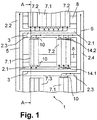
- Schematische Darstellung eines Elektronikschaltschrankes im Schnitt B-B von
Figur 2 - Figur 2:
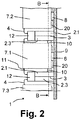
- Schematische Darstellung eines Elektronikschaltschrankes im Schnitt
A-A von Figur 1 - Figur 3:
- Modul mit Kühlöffnungen im mittleren Bereich
- Figur 4:
- Ansicht von oben auf das Modul in
Figur 3
- FIG. 1:
- Schematic representation of an electronic control cabinet in section BB of
FIG. 2 - FIG. 2:
- Schematic representation of an electronic control cabinet in section AA of
FIG. 1 - FIG. 3:
- Module with cooling holes in the middle area
- FIG. 4:
- Top view of the module in
FIG. 3 ,
Die
Zwischen den waagerechten Kanälen 2.1, 2.3 ist eine Trennwand 3 zum Trennen des Luftstromes von Warmluft 6 und Kaltluft 5 angeordnet.
Der Luftstrom 5,6 nimmt durch die Vorrichtung den folgenden Weg. Am unteren Ende des linken senkrechten Kanals 2.2 tritt der Kaltluftstrom 5 in die Vorrichtung ein, strömt nach oben und gelangt in die in mehreren Ebenen angeordneten waagerechten Kanäle 2.1, die sich unterhalb der Gehäuse der Module 7.1,7.2, der Modulreihen befinden. Durch Öffnungen 14.1 für den Luftaustritt in den waagerechten Kanälen 2.1 für Kaltluft zu den Gehäusen der Module 7.1,7.2 wird der Kaltluftstrom 5 mit oder ohne Luftführungskopplung 10 über die Eintrittsöffnungen 15.1 am Gehäuse der Module (in
Between the horizontal channels 2.1, 2.3, a
The
Die Module 7.1, die eine intensive Kühlung erfordern, sind mit den waagerechten Kanälen 2.1 und 2.3 über eine Zwangskühlung verbunden, d. h. zwischen den waagerechten Kanälen 2.1 und 2.3 und dem Gehäuse des Moduls 7.1 sind Luftführungskopplungen 10 zwischen den Öffnungen 14.1 für Luftaustritt im waagerechten Kanal 2.1 und den Eintrittsöffnungen 15.1 am Modulgehäuse angeordnet durch die der Luftstrom der Kaltluft 5 dem Modul 7.1 mit intensiver Kühlung zugeführt wird und durch die Luftführungskopplungen 10 zwischen den Öffnungen 14.2 für Lufteintritt im waagerechten Kanal 2.3 und den Austrittsöffnungen 15.2 am Modulgehäuse wird der Luftstrom der Warmluft 6 von dem Modul 7.1 mit intensiver Kühlung dem waagerechten Kanal 2.3 zurückgeführt und über diesen zum Sammelkanal für Warmluft, zum senkrechten Kanal für Warmluft 2.4 geführt.The modules 7.1, which require intensive cooling, are connected to the horizontal channels 2.1 and 2.3 via forced cooling, d. H. between the horizontal channels 2.1 and 2.3 and the housing of the module 7.1 are
Für Module 7.2 mit einer geringen Kühlung sind die Luftführungskopplungen 10 nicht erforderlich, sondern lediglich Öffnungen 14.1, 14.2 für den Luftaustritt und für den Lufteintritt aus den und in die waagerechten Kanälen 2.1, 2.3. Diese Öffnungen 14.1, 14.2 können verschließbar sein für den Fall, dass die Module 7.2 an einer anderen Stelle angeordnet werden und eine Kühlung an der vorgesehenen Stelle nicht mehr erforderlich ist.For modules 7.2 with a low cooling the
Wie der Schnitt von
Die
The
Die
Die
- 11
- Elektronischer SchaltschrankElectronic control cabinet
- 2.12.1
- Kanal waagerecht für KaltluftChannel horizontal for cold air
- 2.22.2
- Kanal senkrecht für KaltluftChannel vertical for cold air
- 2.32.3
- Kanal waagerecht für WarmluftChannel horizontal for warm air
- 2.42.4
- Kanal senkrecht für WarmluftChannel vertical for warm air
- 33
- Trennwandpartition wall
- 44
- Kabelelectric wire
- 55
- Luftstrom KaltluftAir flow cold air
- 66
- Luftstrom WarmluftAir flow warm air
- 77
- Modulmodule
- 7.17.1
- Modul mit intensiver KühlungModule with intensive cooling
- 7.27.2
- Modul mit geringer KühlungModule with low cooling
- 7.37.3
- Modul ohne KühlungModule without cooling
- 88th
- HutschieneDIN rail
- 99
- Montageplattemounting plate
- 1010
- LuftführungskopplungAir duct coupling
- 1111
- Kabelklemmecable clamp
- 1212
- KabelkanalCabel Canal
- 1313
- Anschluss für Kabel am ModulConnection for cable on the module
- 14.114.1
- Öffnung in 2.1 für LuftaustrittOpening in 2.1 for air outlet
- 14.214.2
- Öffnung in 2.3 für LufteintrittOpening in 2.3 for air intake
- 15.115.1
- Eintrittsöffnungen am Gehäuse des Moduls 7Inlets on the housing of the module. 7
- 15.215.2
-
Austrittsöffnung am Gehäuse des Moduls 7Outlet opening on the housing of the
module 7 - 1616
- Einrastnase am Gehäuse des ModulsSnap-on nose on the housing of the module
- 1717
- Stecker am Gehäuse des Moduls zum Anschluss an das benachbarte ModulPlug on the housing of the module for connection to the adjacent module
- 1919
- Mittlerer Bereich mit WärmeentstehungszoneMiddle area with heat generation zone
- 2020
-
Schnappverbindung gegenüber der Einrastnase am Gehäuse des Moduls 7Snap connection with respect to the latching lug on the housing of the
module 7
Claims (10)
- Electronic switch cabinet (1) for a fire alarm control panel and/or for an extinguishing control panel, comprising a housing with a fastening facility for a module (7) with a housing, in which module electronic assemblies are arranged, wherein- modules (7.1) with intensive cooling, modules (7.2) with weak cooling and modules (7.3) without cooling are able to be arranged in the housing of the switch cabinet (1),- wherein, furthermore, the switch cabinet (1) has for the modules (7, 7.1, 7.2) to be cooled a cooling device comprising a substantially horizontal first and second duct (2.1, 2.3) between two substantially vertical first and second ducts (2.2, 2.4),- wherein the respectively first duct (2.1, 2.2) guides an air stream of cold air (5) to the modules (7, 7.1, 7.2) to be cooled, and the respectively second duct (2.3, 2.4) guides an air stream of hot air (6) away from the modules (7, 7.1, 7.2) to be cooled, and- the horizontal ducts (2.1, 2.3) have openings (14.1, 14.2) for the air stream of the hot and cold air (5, 6) at the positions at which modules (7, 7.1, 7.2) to be cooled are arranged,characterized in that,
for modules (7.1) which are cooled relatively intensively, air-guiding couplings (10) are arranged between the modules (7.1) and the horizontal first and second ducts (2.1, 2.3). - Apparatus according to Claim 1, wherein
the air-guiding couplings (10) between the horizontal ducts (2.1, 2.3) and the housing of the modules (7.1) comprise air-guiding couplings (10) between the openings (14.1) for exit of air in the horizontal duct (2.1) and the inlet openings (15.1) at the module housing, through which couplings the air stream of the cold air (5) is fed to the modules (7.1) with intensive cooling, and comprise air-guiding couplings (10) between the openings (14.2) for entry of air in the horizontal duct (2.3) and the outlet openings (15.2) at the module housing, through which couplings the air stream of the hot air (6) is guided from the module (7.1) with intensive cooling back to the horizontal duct (2.3) and guided via the latter to the collecting duct for hot air, to one of the vertical ducts for hot air (2.4) . - Apparatus according to Claim 1 or Claim 2, characterized in that the horizontal ducts (2.1, 2.3) represent a duct with a separating wall (3).
- Apparatus according to one of Claims 1 to 3, characterized in that the cooling device has at least one fan.
- Apparatus according to one of Claims 1 to 4, characterized in that the cooling device has at least one heat exchanger.
- Apparatus according to one of Claims 1 to 5, characterized in that the openings (14.1, 14.2) have devices for closing.
- Apparatus according to one of Claims 1 to 6, characterized in that devices for guiding cold or hot air (5, 6) are arranged between the openings (14.1, 14.2) and the modules (7.1).
- Apparatus according to Claim 7, characterized in that the devices between the modules (7.1) and the openings (14.1, 14.2) represent air-guiding couplings (10) of circular, semi-circular, oval, angular, rectangular or U-shaped form.
- Apparatus according to one of Claims 1 to 8, characterized in that a cable duct (12) is arranged at or on the horizontal air duct.
- Apparatus according to Claim 9, characterized in that the horizontal cable duct (12) is arranged before the horizontal air duct, and a cable (4) leads from the cable duct (12) into the front part of the module (7, 7.1, 7.2, 7.3).
Priority Applications (3)
| Application Number | Priority Date | Filing Date | Title |
|---|---|---|---|
| EP12198984.2A EP2747533B1 (en) | 2012-12-21 | 2012-12-21 | Electronic switching cabinet with cooling |
| US14/134,059 US20140177170A1 (en) | 2012-12-21 | 2013-12-19 | Electronic Control Cabinet with Cooling |
| CN201310710931.6A CN103887720A (en) | 2012-12-21 | 2013-12-20 | Electronic Control Cabinet With Cooling |
Applications Claiming Priority (1)
| Application Number | Priority Date | Filing Date | Title |
|---|---|---|---|
| EP12198984.2A EP2747533B1 (en) | 2012-12-21 | 2012-12-21 | Electronic switching cabinet with cooling |
Publications (2)
| Publication Number | Publication Date |
|---|---|
| EP2747533A1 EP2747533A1 (en) | 2014-06-25 |
| EP2747533B1 true EP2747533B1 (en) | 2017-11-29 |
Family
ID=47709767
Family Applications (1)
| Application Number | Title | Priority Date | Filing Date |
|---|---|---|---|
| EP12198984.2A Not-in-force EP2747533B1 (en) | 2012-12-21 | 2012-12-21 | Electronic switching cabinet with cooling |
Country Status (3)
| Country | Link |
|---|---|
| US (1) | US20140177170A1 (en) |
| EP (1) | EP2747533B1 (en) |
| CN (1) | CN103887720A (en) |
Families Citing this family (6)
| Publication number | Priority date | Publication date | Assignee | Title |
|---|---|---|---|---|
| JP6526633B2 (en) | 2013-09-26 | 2019-06-05 | エービービー シュヴァイツ アクチェンゲゼルシャフト | Rail mounted control system |
| DE102014101453A1 (en) * | 2014-02-06 | 2015-08-06 | R. Stahl Schaltgeräte GmbH | Control cabinet with air conditioning device |
| DE102014104857A1 (en) * | 2014-04-04 | 2015-10-08 | Armin Meininger | Device for the air conditioning of electronic assemblies |
| DE102014017658A1 (en) * | 2014-11-24 | 2016-05-25 | Friedrich Lütze GmbH | Cooling arrangement |
| CN208462236U (en) * | 2015-03-02 | 2019-02-01 | Abb瑞士股份有限公司 | Control system |
| CN206211354U (en) * | 2016-06-01 | 2017-05-31 | 林楚萍 | A kind of heat dissipation type regulator cubicle of Automated condtrol |
Family Cites Families (29)
| Publication number | Priority date | Publication date | Assignee | Title |
|---|---|---|---|---|
| DE2211268C3 (en) * | 1972-03-09 | 1978-10-12 | Licentia Patent-Verwaltungs-Gmbh, 6000 Frankfurt | Ventilation arrangement for drawers |
| DE2638118B2 (en) | 1976-08-25 | 1978-09-07 | Licentia Patent-Verwaltungs-Gmbh, 6000 Frankfurt | Ventilation module for an electronics cabinet |
| US4277815A (en) * | 1979-06-15 | 1981-07-07 | Westinghouse Electric Corp. | Replaceable air seal for force cooled removable electronic units |
| DE4035213C2 (en) | 1990-11-06 | 1995-01-26 | Vero Electronics Gmbh | Housing with cooling device |
| JPH07202464A (en) * | 1993-12-28 | 1995-08-04 | Toshiba Corp | Electronic appliance, cooling method therefor and fan unit |
| JP3323881B2 (en) * | 1997-05-28 | 2002-09-09 | シャープ株式会社 | Thin cable modem and its mounting stand |
| FI108962B (en) * | 1999-08-20 | 2002-04-30 | Nokia Corp | Cabinet cooling system |
| US6557357B2 (en) * | 2000-02-18 | 2003-05-06 | Toc Technology, Llc | Computer rack heat extraction device |
| US6592449B2 (en) * | 2001-02-24 | 2003-07-15 | International Business Machines Corporation | Smart fan modules and system |
| US6459577B1 (en) * | 2001-07-06 | 2002-10-01 | Apple Computer, Inc. | Thermal chimney for a computer |
| US6889752B2 (en) * | 2002-07-11 | 2005-05-10 | Avaya Technology Corp. | Systems and methods for weatherproof cabinets with multiple compartment cooling |
| US6611428B1 (en) * | 2002-08-12 | 2003-08-26 | Motorola, Inc. | Cabinet for cooling electronic modules |
| EP1413997B1 (en) * | 2002-10-22 | 2009-01-14 | EAS Schaltanlagen GmbH | Arrangement for detecting a smoke generation and/or a fire in a switch cabinet or the like for activating a fire alarm and method of operation thereof |
| US7500911B2 (en) * | 2002-11-25 | 2009-03-10 | American Power Conversion Corporation | Exhaust air removal system |
| US7112131B2 (en) * | 2003-05-13 | 2006-09-26 | American Power Conversion Corporation | Rack enclosure |
| US6819563B1 (en) * | 2003-07-02 | 2004-11-16 | International Business Machines Corporation | Method and system for cooling electronics racks using pre-cooled air |
| DE102004030785B3 (en) * | 2004-03-15 | 2005-11-10 | Pfannenberg Gmbh | Cooling device for electrical cabinet for explosive environments, has welded sealed housing containing components not certified for explosive environments, and second housing for certified components |
| US7104081B2 (en) * | 2004-03-30 | 2006-09-12 | International Business Machines Corproation | Condensate removal system and method for facilitating cooling of an electronics system |
| DE202004006552U1 (en) * | 2004-04-26 | 2004-07-08 | Knürr AG | Cooling system for device and network cabinets |
| US7916502B2 (en) * | 2007-02-22 | 2011-03-29 | Tellabs Operations, Inc. | Stackable cable tray |
| EP2073618B1 (en) * | 2007-12-17 | 2011-01-26 | Siemens Aktiengesellschaft | Electronic device |
| CN101299571B (en) * | 2008-03-14 | 2011-05-11 | 北京合康亿盛变频科技股份有限公司 | Circulated cold air apparatus for high voltage frequency conversion equipment |
| JP4951596B2 (en) * | 2008-07-31 | 2012-06-13 | 株式会社日立製作所 | Cooling system and electronic device |
| DE102009043455A1 (en) * | 2009-09-29 | 2011-04-07 | Siemens Aktiengesellschaft | Arrangement for installing building system technology devices |
| DE102010002295A1 (en) * | 2010-02-24 | 2011-08-25 | Liebold, Edgar, 08064 | Fire alarm for monitoring system in building center, has fire alarm and room monitoring modules arranged in cabinets and including evaluation units and sensors, where modules are functionally operated and interchanged from each other |
| US8248793B2 (en) * | 2010-03-29 | 2012-08-21 | Hewlett-Packard Development Company, L.P. | Electronic component having a movable louver |
| EP2479861B1 (en) * | 2011-01-19 | 2016-12-14 | Siemens Aktiengesellschaft | Automation device |
| US8743549B2 (en) * | 2011-03-22 | 2014-06-03 | Amazon Technologies, Inc. | Modular mass storage system |
| CN102186329B (en) * | 2011-05-04 | 2013-06-19 | 中航光电科技股份有限公司 | Cooling device used for electronic equipment |
-
2012
- 2012-12-21 EP EP12198984.2A patent/EP2747533B1/en not_active Not-in-force
-
2013
- 2013-12-19 US US14/134,059 patent/US20140177170A1/en not_active Abandoned
- 2013-12-20 CN CN201310710931.6A patent/CN103887720A/en active Pending
Non-Patent Citations (1)
| Title |
|---|
| None * |
Also Published As
| Publication number | Publication date |
|---|---|
| EP2747533A1 (en) | 2014-06-25 |
| US20140177170A1 (en) | 2014-06-26 |
| CN103887720A (en) | 2014-06-25 |
Similar Documents
| Publication | Publication Date | Title |
|---|---|---|
| EP2747533B1 (en) | Electronic switching cabinet with cooling | |
| EP0878991B1 (en) | Cabinet frame for supporting equipment with ventilation device | |
| EP1614333B1 (en) | Cooling system for equipment and wiring cabinets and method for cooling equipment and wiring cabinets | |
| EP1967938A1 (en) | Control cabinet for electronic plug-in components with a heat exchanger | |
| WO2005081091A2 (en) | Assembly of devices | |
| EP1853101A1 (en) | Components carrier with a casing for plug-in components | |
| DE102009054011B4 (en) | Cooling arrangement for arranged in a cabinet electrical equipment | |
| EP1895824B1 (en) | Assembly for an automation device | |
| DE202009015124U1 (en) | Arrangement for cooling electrical and electronic components and modular units in equipment cabinets | |
| EP3066904B1 (en) | Functional component for a component construction system | |
| EP3281506A1 (en) | Electrical enclosure arrangement comprising an electrical enclosure line and a cooling device connected into the line | |
| DE102009057129A1 (en) | Ventilation device for components of an electronic or computer cabinet | |
| DE3837029C2 (en) | ||
| WO2018206030A1 (en) | Heat dissipation arrangement for a switchgear cabinet | |
| DE102014201483B4 (en) | Cuboid housing for an electronics module, electronic module and arrangement for cooling at least one electronic module | |
| DE202006013162U1 (en) | Cooling device for cooling electrical cabinet, has axial blower to produce two air flows, and assembly unit implemented with cartridges and blowers, where cooling and ambient air flows in two flows, respectively, through exchanger cartridge | |
| DE3507255A1 (en) | HOUSING FOR ELECTRICAL COMPONENTS | |
| DE2015361B2 (en) | Cooling system for spaced circuit boards - has hollow board support rails with apertures directing air behind apertured plates which direct air onto specific components | |
| DE10326355B3 (en) | Air guiding device for cooling a switch part of an electrical switch | |
| EP2801137A1 (en) | Busbar system especially for long vertical paths | |
| AT13912U1 (en) | Cable cabinet with depth extension | |
| DE4035212A1 (en) | Housing system for modular electronic appts. - has guide rails for circuit board parallel to front plate of retractable frame | |
| DE2740772B2 (en) | Device for dissipating heat loss from electronic assemblies | |
| WO2015028290A1 (en) | Data processing system | |
| DE3151301A1 (en) | Cabinet for holding electrical components |
Legal Events
| Date | Code | Title | Description |
|---|---|---|---|
| PUAI | Public reference made under article 153(3) epc to a published international application that has entered the european phase |
Free format text: ORIGINAL CODE: 0009012 |
|
| 17P | Request for examination filed |
Effective date: 20121221 |
|
| AK | Designated contracting states |
Kind code of ref document: A1 Designated state(s): AL AT BE BG CH CY CZ DE DK EE ES FI FR GB GR HR HU IE IS IT LI LT LU LV MC MK MT NL NO PL PT RO RS SE SI SK SM TR |
|
| AX | Request for extension of the european patent |
Extension state: BA ME |
|
| R17P | Request for examination filed (corrected) |
Effective date: 20150105 |
|
| RBV | Designated contracting states (corrected) |
Designated state(s): AL AT BE BG CH CY CZ DE DK EE ES FI FR GB GR HR HU IE IS IT LI LT LU LV MC MK MT NL NO PL PT RO RS SE SI SK SM TR |
|
| 17Q | First examination report despatched |
Effective date: 20170203 |
|
| GRAP | Despatch of communication of intention to grant a patent |
Free format text: ORIGINAL CODE: EPIDOSNIGR1 |
|
| INTG | Intention to grant announced |
Effective date: 20170912 |
|
| GRAS | Grant fee paid |
Free format text: ORIGINAL CODE: EPIDOSNIGR3 |
|
| GRAA | (expected) grant |
Free format text: ORIGINAL CODE: 0009210 |
|
| AK | Designated contracting states |
Kind code of ref document: B1 Designated state(s): AL AT BE BG CH CY CZ DE DK EE ES FI FR GB GR HR HU IE IS IT LI LT LU LV MC MK MT NL NO PL PT RO RS SE SI SK SM TR |
|
| REG | Reference to a national code |
Ref country code: CH Ref legal event code: EP |
|
| REG | Reference to a national code |
Ref country code: AT Ref legal event code: REF Ref document number: 951472 Country of ref document: AT Kind code of ref document: T Effective date: 20171215 |
|
| REG | Reference to a national code |
Ref country code: IE Ref legal event code: FG4D Free format text: LANGUAGE OF EP DOCUMENT: GERMAN |
|
| REG | Reference to a national code |
Ref country code: FR Ref legal event code: PLFP Year of fee payment: 6 |
|
| REG | Reference to a national code |
Ref country code: DE Ref legal event code: R096 Ref document number: 502012011727 Country of ref document: DE |
|
| REG | Reference to a national code |
Ref country code: NL Ref legal event code: FP |
|
| REG | Reference to a national code |
Ref country code: LT Ref legal event code: MG4D |
|
| PG25 | Lapsed in a contracting state [announced via postgrant information from national office to epo] |
Ref country code: SE Free format text: LAPSE BECAUSE OF FAILURE TO SUBMIT A TRANSLATION OF THE DESCRIPTION OR TO PAY THE FEE WITHIN THE PRESCRIBED TIME-LIMIT Effective date: 20171129 Ref country code: LT Free format text: LAPSE BECAUSE OF FAILURE TO SUBMIT A TRANSLATION OF THE DESCRIPTION OR TO PAY THE FEE WITHIN THE PRESCRIBED TIME-LIMIT Effective date: 20171129 Ref country code: FI Free format text: LAPSE BECAUSE OF FAILURE TO SUBMIT A TRANSLATION OF THE DESCRIPTION OR TO PAY THE FEE WITHIN THE PRESCRIBED TIME-LIMIT Effective date: 20171129 Ref country code: ES Free format text: LAPSE BECAUSE OF FAILURE TO SUBMIT A TRANSLATION OF THE DESCRIPTION OR TO PAY THE FEE WITHIN THE PRESCRIBED TIME-LIMIT Effective date: 20171129 Ref country code: NO Free format text: LAPSE BECAUSE OF FAILURE TO SUBMIT A TRANSLATION OF THE DESCRIPTION OR TO PAY THE FEE WITHIN THE PRESCRIBED TIME-LIMIT Effective date: 20180228 |
|
| PG25 | Lapsed in a contracting state [announced via postgrant information from national office to epo] |
Ref country code: HR Free format text: LAPSE BECAUSE OF FAILURE TO SUBMIT A TRANSLATION OF THE DESCRIPTION OR TO PAY THE FEE WITHIN THE PRESCRIBED TIME-LIMIT Effective date: 20171129 Ref country code: LV Free format text: LAPSE BECAUSE OF FAILURE TO SUBMIT A TRANSLATION OF THE DESCRIPTION OR TO PAY THE FEE WITHIN THE PRESCRIBED TIME-LIMIT Effective date: 20171129 Ref country code: RS Free format text: LAPSE BECAUSE OF FAILURE TO SUBMIT A TRANSLATION OF THE DESCRIPTION OR TO PAY THE FEE WITHIN THE PRESCRIBED TIME-LIMIT Effective date: 20171129 Ref country code: GR Free format text: LAPSE BECAUSE OF FAILURE TO SUBMIT A TRANSLATION OF THE DESCRIPTION OR TO PAY THE FEE WITHIN THE PRESCRIBED TIME-LIMIT Effective date: 20180301 Ref country code: BG Free format text: LAPSE BECAUSE OF FAILURE TO SUBMIT A TRANSLATION OF THE DESCRIPTION OR TO PAY THE FEE WITHIN THE PRESCRIBED TIME-LIMIT Effective date: 20180228 |
|
| PG25 | Lapsed in a contracting state [announced via postgrant information from national office to epo] |
Ref country code: CY Free format text: LAPSE BECAUSE OF FAILURE TO SUBMIT A TRANSLATION OF THE DESCRIPTION OR TO PAY THE FEE WITHIN THE PRESCRIBED TIME-LIMIT Effective date: 20171129 Ref country code: CZ Free format text: LAPSE BECAUSE OF FAILURE TO SUBMIT A TRANSLATION OF THE DESCRIPTION OR TO PAY THE FEE WITHIN THE PRESCRIBED TIME-LIMIT Effective date: 20171129 Ref country code: EE Free format text: LAPSE BECAUSE OF FAILURE TO SUBMIT A TRANSLATION OF THE DESCRIPTION OR TO PAY THE FEE WITHIN THE PRESCRIBED TIME-LIMIT Effective date: 20171129 Ref country code: SK Free format text: LAPSE BECAUSE OF FAILURE TO SUBMIT A TRANSLATION OF THE DESCRIPTION OR TO PAY THE FEE WITHIN THE PRESCRIBED TIME-LIMIT Effective date: 20171129 Ref country code: DK Free format text: LAPSE BECAUSE OF FAILURE TO SUBMIT A TRANSLATION OF THE DESCRIPTION OR TO PAY THE FEE WITHIN THE PRESCRIBED TIME-LIMIT Effective date: 20171129 |
|
| REG | Reference to a national code |
Ref country code: DE Ref legal event code: R097 Ref document number: 502012011727 Country of ref document: DE |
|
| PG25 | Lapsed in a contracting state [announced via postgrant information from national office to epo] |
Ref country code: IT Free format text: LAPSE BECAUSE OF FAILURE TO SUBMIT A TRANSLATION OF THE DESCRIPTION OR TO PAY THE FEE WITHIN THE PRESCRIBED TIME-LIMIT Effective date: 20171129 Ref country code: RO Free format text: LAPSE BECAUSE OF FAILURE TO SUBMIT A TRANSLATION OF THE DESCRIPTION OR TO PAY THE FEE WITHIN THE PRESCRIBED TIME-LIMIT Effective date: 20171129 Ref country code: SM Free format text: LAPSE BECAUSE OF FAILURE TO SUBMIT A TRANSLATION OF THE DESCRIPTION OR TO PAY THE FEE WITHIN THE PRESCRIBED TIME-LIMIT Effective date: 20171129 Ref country code: PL Free format text: LAPSE BECAUSE OF FAILURE TO SUBMIT A TRANSLATION OF THE DESCRIPTION OR TO PAY THE FEE WITHIN THE PRESCRIBED TIME-LIMIT Effective date: 20171129 |
|
| REG | Reference to a national code |
Ref country code: IE Ref legal event code: MM4A |
|
| PG25 | Lapsed in a contracting state [announced via postgrant information from national office to epo] |
Ref country code: MT Free format text: LAPSE BECAUSE OF FAILURE TO SUBMIT A TRANSLATION OF THE DESCRIPTION OR TO PAY THE FEE WITHIN THE PRESCRIBED TIME-LIMIT Effective date: 20171129 Ref country code: LU Free format text: LAPSE BECAUSE OF NON-PAYMENT OF DUE FEES Effective date: 20171221 |
|
| PLBE | No opposition filed within time limit |
Free format text: ORIGINAL CODE: 0009261 |
|
| STAA | Information on the status of an ep patent application or granted ep patent |
Free format text: STATUS: NO OPPOSITION FILED WITHIN TIME LIMIT |
|
| REG | Reference to a national code |
Ref country code: BE Ref legal event code: MM Effective date: 20171231 |
|
| PG25 | Lapsed in a contracting state [announced via postgrant information from national office to epo] |
Ref country code: IE Free format text: LAPSE BECAUSE OF NON-PAYMENT OF DUE FEES Effective date: 20171221 |
|
| 26N | No opposition filed |
Effective date: 20180830 |
|
| PG25 | Lapsed in a contracting state [announced via postgrant information from national office to epo] |
Ref country code: BE Free format text: LAPSE BECAUSE OF NON-PAYMENT OF DUE FEES Effective date: 20171231 Ref country code: SI Free format text: LAPSE BECAUSE OF FAILURE TO SUBMIT A TRANSLATION OF THE DESCRIPTION OR TO PAY THE FEE WITHIN THE PRESCRIBED TIME-LIMIT Effective date: 20171129 |
|
| PG25 | Lapsed in a contracting state [announced via postgrant information from national office to epo] |
Ref country code: MC Free format text: LAPSE BECAUSE OF FAILURE TO SUBMIT A TRANSLATION OF THE DESCRIPTION OR TO PAY THE FEE WITHIN THE PRESCRIBED TIME-LIMIT Effective date: 20171129 Ref country code: HU Free format text: LAPSE BECAUSE OF FAILURE TO SUBMIT A TRANSLATION OF THE DESCRIPTION OR TO PAY THE FEE WITHIN THE PRESCRIBED TIME-LIMIT; INVALID AB INITIO Effective date: 20121221 |
|
| PG25 | Lapsed in a contracting state [announced via postgrant information from national office to epo] |
Ref country code: MK Free format text: LAPSE BECAUSE OF FAILURE TO SUBMIT A TRANSLATION OF THE DESCRIPTION OR TO PAY THE FEE WITHIN THE PRESCRIBED TIME-LIMIT Effective date: 20171129 |
|
| PGFP | Annual fee paid to national office [announced via postgrant information from national office to epo] |
Ref country code: NL Payment date: 20191217 Year of fee payment: 8 |
|
| PG25 | Lapsed in a contracting state [announced via postgrant information from national office to epo] |
Ref country code: TR Free format text: LAPSE BECAUSE OF FAILURE TO SUBMIT A TRANSLATION OF THE DESCRIPTION OR TO PAY THE FEE WITHIN THE PRESCRIBED TIME-LIMIT Effective date: 20171129 |
|
| PGFP | Annual fee paid to national office [announced via postgrant information from national office to epo] |
Ref country code: CH Payment date: 20191220 Year of fee payment: 8 Ref country code: AT Payment date: 20191213 Year of fee payment: 8 |
|
| PG25 | Lapsed in a contracting state [announced via postgrant information from national office to epo] |
Ref country code: PT Free format text: LAPSE BECAUSE OF FAILURE TO SUBMIT A TRANSLATION OF THE DESCRIPTION OR TO PAY THE FEE WITHIN THE PRESCRIBED TIME-LIMIT Effective date: 20171129 |
|
| PG25 | Lapsed in a contracting state [announced via postgrant information from national office to epo] |
Ref country code: IS Free format text: LAPSE BECAUSE OF FAILURE TO SUBMIT A TRANSLATION OF THE DESCRIPTION OR TO PAY THE FEE WITHIN THE PRESCRIBED TIME-LIMIT Effective date: 20180329 Ref country code: AL Free format text: LAPSE BECAUSE OF FAILURE TO SUBMIT A TRANSLATION OF THE DESCRIPTION OR TO PAY THE FEE WITHIN THE PRESCRIBED TIME-LIMIT Effective date: 20171129 |
|
| REG | Reference to a national code |
Ref country code: CH Ref legal event code: PL |
|
| REG | Reference to a national code |
Ref country code: NL Ref legal event code: MM Effective date: 20210101 |
|
| REG | Reference to a national code |
Ref country code: AT Ref legal event code: MM01 Ref document number: 951472 Country of ref document: AT Kind code of ref document: T Effective date: 20201221 |
|
| PG25 | Lapsed in a contracting state [announced via postgrant information from national office to epo] |
Ref country code: NL Free format text: LAPSE BECAUSE OF NON-PAYMENT OF DUE FEES Effective date: 20210101 |
|
| PG25 | Lapsed in a contracting state [announced via postgrant information from national office to epo] |
Ref country code: AT Free format text: LAPSE BECAUSE OF NON-PAYMENT OF DUE FEES Effective date: 20201221 |
|
| PG25 | Lapsed in a contracting state [announced via postgrant information from national office to epo] |
Ref country code: LI Free format text: LAPSE BECAUSE OF NON-PAYMENT OF DUE FEES Effective date: 20201231 Ref country code: CH Free format text: LAPSE BECAUSE OF NON-PAYMENT OF DUE FEES Effective date: 20201231 |
|
| REG | Reference to a national code |
Ref country code: DE Ref legal event code: R081 Ref document number: 502012011727 Country of ref document: DE Owner name: MINIMAX GMBH, DE Free format text: FORMER OWNER: MINIMAX GMBH & CO. KG, 23843 BAD OLDESLOE, DE |
|
| PGFP | Annual fee paid to national office [announced via postgrant information from national office to epo] |
Ref country code: FR Payment date: 20211220 Year of fee payment: 10 Ref country code: GB Payment date: 20211222 Year of fee payment: 10 |
|
| PGFP | Annual fee paid to national office [announced via postgrant information from national office to epo] |
Ref country code: DE Payment date: 20211220 Year of fee payment: 10 |
|
| REG | Reference to a national code |
Ref country code: DE Ref legal event code: R119 Ref document number: 502012011727 Country of ref document: DE |
|
| GBPC | Gb: european patent ceased through non-payment of renewal fee |
Effective date: 20221221 |
|
| PG25 | Lapsed in a contracting state [announced via postgrant information from national office to epo] |
Ref country code: GB Free format text: LAPSE BECAUSE OF NON-PAYMENT OF DUE FEES Effective date: 20221221 Ref country code: DE Free format text: LAPSE BECAUSE OF NON-PAYMENT OF DUE FEES Effective date: 20230701 |
|
| PG25 | Lapsed in a contracting state [announced via postgrant information from national office to epo] |
Ref country code: FR Free format text: LAPSE BECAUSE OF NON-PAYMENT OF DUE FEES Effective date: 20221231 |