EP2746971A2 - Replication mechanisms for database environments - Google Patents
Replication mechanisms for database environments Download PDFInfo
- Publication number
- EP2746971A2 EP2746971A2 EP13198236.5A EP13198236A EP2746971A2 EP 2746971 A2 EP2746971 A2 EP 2746971A2 EP 13198236 A EP13198236 A EP 13198236A EP 2746971 A2 EP2746971 A2 EP 2746971A2
- Authority
- EP
- European Patent Office
- Prior art keywords
- source database
- replica
- database table
- data
- replication
- Prior art date
- Legal status (The legal status is an assumption and is not a legal conclusion. Google has not performed a legal analysis and makes no representation as to the accuracy of the status listed.)
- Ceased
Links
- 230000010076 replication Effects 0.000 title claims abstract description 61
- 230000007246 mechanism Effects 0.000 title description 5
- 238000011084 recovery Methods 0.000 claims abstract description 46
- 238000005192 partition Methods 0.000 claims abstract description 22
- 238000000638 solvent extraction Methods 0.000 claims abstract description 17
- 238000000034 method Methods 0.000 claims description 40
- 238000004891 communication Methods 0.000 claims description 19
- 238000004590 computer program Methods 0.000 claims description 13
- 238000012508 change request Methods 0.000 claims description 5
- 230000001902 propagating effect Effects 0.000 claims description 3
- 230000015654 memory Effects 0.000 description 14
- 238000012545 processing Methods 0.000 description 11
- 238000012986 modification Methods 0.000 description 9
- 230000004048 modification Effects 0.000 description 9
- 230000008569 process Effects 0.000 description 9
- 238000012360 testing method Methods 0.000 description 8
- 238000012217 deletion Methods 0.000 description 6
- 230000037430 deletion Effects 0.000 description 6
- 230000003287 optical effect Effects 0.000 description 4
- 238000013459 approach Methods 0.000 description 3
- 230000008901 benefit Effects 0.000 description 3
- 239000003795 chemical substances by application Substances 0.000 description 3
- 230000008859 change Effects 0.000 description 2
- 238000010586 diagram Methods 0.000 description 2
- 238000003780 insertion Methods 0.000 description 2
- 230000037431 insertion Effects 0.000 description 2
- 238000005259 measurement Methods 0.000 description 2
- 238000010606 normalization Methods 0.000 description 2
- 230000002688 persistence Effects 0.000 description 2
- WVCHIGAIXREVNS-UHFFFAOYSA-N 2-hydroxy-1,4-naphthoquinone Chemical compound C1=CC=C2C(O)=CC(=O)C(=O)C2=C1 WVCHIGAIXREVNS-UHFFFAOYSA-N 0.000 description 1
- 238000007792 addition Methods 0.000 description 1
- 239000000654 additive Substances 0.000 description 1
- 230000000996 additive effect Effects 0.000 description 1
- 230000005540 biological transmission Effects 0.000 description 1
- 239000006227 byproduct Substances 0.000 description 1
- 230000001413 cellular effect Effects 0.000 description 1
- 238000010276 construction Methods 0.000 description 1
- 238000013479 data entry Methods 0.000 description 1
- 230000000694 effects Effects 0.000 description 1
- 230000008030 elimination Effects 0.000 description 1
- 238000003379 elimination reaction Methods 0.000 description 1
- 239000000835 fiber Substances 0.000 description 1
- 230000003993 interaction Effects 0.000 description 1
- 238000004806 packaging method and process Methods 0.000 description 1
- 239000000047 product Substances 0.000 description 1
- 239000004065 semiconductor Substances 0.000 description 1
Images


Classifications
-
- G—PHYSICS
- G06—COMPUTING; CALCULATING OR COUNTING
- G06F—ELECTRIC DIGITAL DATA PROCESSING
- G06F16/00—Information retrieval; Database structures therefor; File system structures therefor
- G06F16/20—Information retrieval; Database structures therefor; File system structures therefor of structured data, e.g. relational data
- G06F16/27—Replication, distribution or synchronisation of data between databases or within a distributed database system; Distributed database system architectures therefor
- G06F16/278—Data partitioning, e.g. horizontal or vertical partitioning
-
- G—PHYSICS
- G06—COMPUTING; CALCULATING OR COUNTING
- G06F—ELECTRIC DIGITAL DATA PROCESSING
- G06F16/00—Information retrieval; Database structures therefor; File system structures therefor
- G06F16/20—Information retrieval; Database structures therefor; File system structures therefor of structured data, e.g. relational data
- G06F16/27—Replication, distribution or synchronisation of data between databases or within a distributed database system; Distributed database system architectures therefor
Definitions
- Embodiments relate generally to data processing environments and, more particularly, to a system providing data replication using a partitioning scheme.
- Computers are powerful tools for storing and providing access to vast amounts of information.
- Computer databases are a common mechanism for storing information on computer systems while providing easy access to users.
- a typical database is an organized collection of related information stored as "records" having "fields" of information.
- a business may have a database of employees.
- the database of employees may have a record for each employee where each record includes fields designating specific properties or information about any employee, such as, but not limited to the employee's name, contact information, and salary.
- a database management system or DBMS is typically provided as a software cushion or layer.
- the DBMS shields the database user from knowing or even caring about the underlying hardware-level details.
- all requests from users for access to the data are processed by the DBMS. For example, information may be added or removed from data files, information retrieved from or updated in such files, all without user knowledge of the underlying system implementation.
- the DBMS provides users with a conceptual view of the database that is removed from the hardware level.
- the general construction and operation of database management systems is well known in the art.
- Certain tables of a database may perform join operations. During the join operation it is often required to move or copy the tables or intermediate results to other hosts of the same database instance, which is called a remote join. This significantly affects performance. Therefore it is reasonable to have local replicas on all relevant servers. However, replication causes a higher memory consumption and affects overall system performance.
- a record When a row is inserted into a table, a record is written into a delta log. At this moment in time, an entry is also written into a recovery (redo) log. If a user performs a recovery operation of the database, not only the backup files but also the recovery log is taken into consideration. After the restoration of the backup files, the recovery log is read and in this way the delta log is restored at file level. Upon table access, the delta log is read and the data becomes available for processing.
- a DBMS offers the ability to initially create replica of a non-replicated table.
- the non-replicated table is copied n times for all required replica.
- the problematic aspect is when a recovery operation is performed, the copy functionality has to work with backup and recovery functionality in a way that after recovery all data is replicated again.
- the simple approach to achieve this is to write all copies of the original table into the recovery log of the database. This file is read during recovery and based on its contents, all replicates are being restored. This approach has a negative effect, however, as the tables that are subject for replication are usually very large and writing them n times for n copies into the recovery log causes files that are extremely big.
- a replication mechanism that is substantially transparent to components of the database system. Specifically, what is needed is a replication mechanism that uses other database engine infrastructures (like a partitioning feature) in which the components "think" of replication as a partitioned table - one with just a single partition, in which the single partition is the local replica.
- data replication includes identifying a source database.
- the source database includes a main index file and a delta log file.
- One or more symbolic links to the source database are generated.
- the symbolic links identify a path to a physical location of the source database.
- a replica of the source database is generated based on symbolic links.
- the replica includes a copy of the main index file and delta log file. Information associated with the replica and the one or more symbolic links is stored in a recovery log.
- FIG. 1 illustrates the general structure of a client/server database system 100 suitable for implementing embodiments.
- the system 100 comprises one or more client computing device(s) 110 connected to a server 130 via a network 120.
- the client computing device(s) 110 comprise one or more standalone terminals connected to a Database Management System 140 ("DBMS") using a conventional network 120.
- DBMS Database Management System
- the terminals may themselves comprise a plurality of standalone workstations, dumb terminals, or the like, or comprise personal computers (PCs).
- client operating system such as a Microsoft® Windows, Unix, Apple®, etc., client operating system
- the database server system 130 which comprises SAP® HANA® (available from SAP) in an exemplary embodiment, generally operates as an independent process (i.e., independently of the client computing devices), running under a server operating system such as Microsoft® Windows NT, Windows 2000, Windows XP, Windows Vista and Windows 7 (all from Microsoft Corporation of Redmond, Wash.), UNIX (Novell), Solaris (Sun), or Linux (Red Hat).
- the network 120 may be any one of a number of conventional wired and/or wireless network systems, including a Local Area Network (LAN) or Wide Area Network (WAN), as is known in the art (e.g., using Ethernet, IBM Token Ring, or the like).
- the network 120 includes functionality for packaging client calls in the well-known Structured Query Language (SQL) together with any parameter information into a format (of one or more packets) suitable for transmission to the database server system 140.
- SQL Structured Query Language
- the described computer hardware and software are presented for purposes of illustrating the basic underlying desktop and server computer components that may be employed for implementing embodiments of the present invention. For purposes of discussion, the following description will present examples in which it will be assumed that there exist multiple server instances (e.g., database server nodes) in a cluster that communicate with one or more "clients" (e.g., personal computers or mobile devices).
- the embodiments of the present invention is not limited to any particular environment or device configuration. Instead, embodiments may be implemented in any type of system architecture or processing environment capable of supporting the methodologies presented herein.
- the client computing device(s) 110 store data in, or retrieve data from, one or more source database tables 150, as shown at FIG. 1 .
- Data in a relational database is stored as a series of tables, also called relations.
- each table itself comprises one or more "rows” or “records” (tuples) (e.g., row 155 as shown at FIG. 1 ).
- a typical database will include many tables, each of which stores information about a particular type of entity.
- a table in a typical relational database may contain anywhere from a few rows to millions of rows.
- a row is divided into fields or columns; each field represents one particular attribute of the given row.
- a row corresponding to an employee record may include information about the employee's ID Number, Last Name and First Initial, Position, Date Hired, Social Security Number (SSN), and Salary.
- Each of these categories represents a database field.
- Position is one field
- Date Hired is another, and so on.
- tables are easy for users to understand and use.
- the flexibility of tables permits a user to define relationships between various items of data, as needed.
- a typical record includes several categories of information about an individual person, place, or thing.
- Each row in a table is uniquely identified by a record ID (RID), which can be used as a pointer to a given row.
- RID record ID
- SQL Structured Query Language
- DML data manipulation language
- DDL data definition language
- SQL statements are also called queries.
- the client computing device(s) 110 issue one or more SQL commands to the server 130.
- SQL commands may specify, for instance, a query for retrieving particular data (i.e., data records meeting the query condition) from the database table(s) 150.
- the clients 110 also have the ability to issue commands to insert new rows of data records into the table(s), or to update and/or delete existing records in the table(s).
- the SQL statements received from the client(s) 110 are processed by the source database engine 160 of the DBMS 140.
- the source database engine 160 itself comprises a parser 161, a normalizer 163, a compiler 165, an execution unit 169, and access method(s) 170.
- the SQL statements are passed to the parser 161 which employs conventional parsing methodology (e.g., recursive descent parsing).
- the parsed query is then normalized by the normalizer 163. Normalization includes, for example, the elimination of redundant data.
- the normalizer 163 performs error checking, such as confirming that table names and column names which appear in the query are valid (e.g., are available and belong together). Finally, the normalizer 163 can also look-up any referential integrity constraints which exist and add those to the query.
- the query is passed to the compiler 165, which includes an optimizer 166 and a code generator 167.
- the optimizer 166 performs a cost-based analysis for formulating a query plan that is reasonably close to an optimal plan.
- the code generator 167 translates the query plan into executable form for execution.
- the execution unit 169 executes the query plan using the access methods 170.
- a database management system such as DBMS 140, may replicate database tables.
- FIG. 2 is a system 200 in which embodiments, or portions thereof, can be implemented.
- Source database engine 160 communicates over network 120 with replication server 206, in accordance with an embodiment.
- the replication agent 202 facilitates the replication process by, in accordance with an embodiment, scanning a transaction log 212 for changes at source database engine 160 and sending those changes to replication server 206.
- the network 120 can be configured in a number of ways in order to achieve the same result, and the aforementioned configuration is shown by way of example, and not limitation.
- replication agent 202 and source database engine 160 are located in a single physical computing device or cluster of computing devices.
- Source database engine 160 includes a source database or main index 210 and a transaction log or delta log 212, in accordance with an embodiment.
- Each transactional operation such as inserts, updates, and deletes to the source database 210, causes a log record to be written to the transaction (delta) log 212.
- Each particular delta log record characterizes the change which has occurred to the source database or main index 210 during processing of a transaction.
- These log records can be used, for instance, in error recovery, to restore the source database engine 160 to a preexisting, consistent state.
- changes to the source database engine 160 are sent to replication server 206 over network 120, which then applies these changes, over network 120, directly to target database 204.
- the replication server 206 starts threads, which are responsible for transferring the data from an outbound queue to the target database 204.
- replication server 206 is configured to identify the source database based on the query received.
- a source database has an internal object identifier and optionally a name associated with it.
- the internal object identifier is retrievable by replication server 206 upon receiving a query request, such as a SQL query.
- a SQL query may specify retrieving, updating or deleting particular data (i.e., data records meeting the query condition) from the source database table.
- source database engine 160 Upon receiving the SQL query and updating the source database table 210, source database engine 160 sends information associated with the SQL query to replication server 206.
- the information can include the internal object identifier of the source database engine 160.
- the internal object identifier can identify the name and location of the source database, according to embodiments.
- Replication server 206 receives the SQL query and generates at least one symbolic link to the source database engine.
- the symbolic link identifies a path to the source database engine 160 and its associated source database 210 and delta log 212.
- a symbolic link can be a file that includes a reference to source database engine 160 in the form of an absolute or relative path. Symbolic links operate transparently for most operations. Thus programs that read or write to files named by a symbolic link will behave as if operating directly on the target file. However, programs that need to handle symbolic links specially (e.g., backup utilities) may identify and manipulate them directly.
- a symbolic link includes a text string that is automatically interpreted and followed by the persistence layer of the database as a path to the source database engine 160. The symbolic link exists independently of the source database engine 160.
- Replication server 206 generates a replica at target database 204 based on the generated symbolic links.
- the replica is a copy of the source database engine 160 and its associated files.
- the replica includes at least a copy of the main index 210 and delta log 212 of the source database engine 160. Since the replica is generated based on the symbolic links, which is essentially a pointer and soft link to the source database engine 160, only a few data entries are written to the Recovery Log 214. Before further insertions, modifications, and deletions of data may occur, the symbolic links of Target Database 204 have to be materialized. During this step, the source data of 210 and 212 is read and persisted locally. However, the important aspect is that the data is not written to the Recovery Log 214.
- the actual change to delta structures is broadcasted from the Source Database Engine 160 to all Target Databases 204.
- the inserts, modifications and deletions are written into each delta log (source and target systems) as well as n times to the Recovery Log 214.
- recovery log 214 keeps track of the symbolic links and any delta log changes. In other words, new changes are still written n times to the recovery log 214 - but the initial copy step causes minimal data volume. Accordingly, the recovery log 214 can be kept at a more manageable size and thus increase system performance.
- the replicas of target database 204 are materialized. Materialization includes the physical copying of the data from source database engine 160 to the target database 204. As noted previously, since the replicas are initially created via symbolic links, the files associated with the target database 204 are initially empty with the exception of the symbolic link information. During a materialization step, which may occur explicitly or take place during a delta merge of tables, the data in the source database 160 is copied to the target database 204. Thus, the main index file and the delta log file (not illustrated) of the target database 204 will now have a mirror copy of the contents in the source database 210 and delta log 212. Once materialization is accomplished, the symbolic link is removed and the contents of the source database engine 160 are deleted.
- the recovery log 214 is opened and read. Since recovery log 214 includes information associated with the symbolic link, the recovery log 214 can be used to restore the original source database engine 160 along with all of its replicas at the time when the copy process took place. If the replicas were changed after the copy process, these changes will also be replayed from the recovery log 214. According to embodiments, all n replicas recover from a single copy of the data. If the administrator creates a new backup after the replicas have been materialized, the complete data of all replicas will be stored n times for n replicas in the backup media. Using this mechanism, full copies of the source table will be created on all relevant servers. At the same time, the symbolic links assure that backup and recovery works without creating a large recovery log.
- FIG. 3A illustrates an exemplary replication process and shows a server 302 and a server 304.
- Server 302 includes source database table 306 which comprises a main index 320 and a delta log 330.
- a replication of source database table 306 is accomplished via the generation of symbolic links 310.
- Each symbolic link 310 creates a soft link from the source database table 306 to its associated replica 308.
- Replica 308-A is created on server 302-A via symbolic links 310-A and 310-B.
- replica 308-B is created on server 304 via symbolic links 310-C and 310-D.
- each replica 308 can include a main index 312 and delta log 314 which mirrors the contents of main index 320 and delta log 330 of source database table 306.
- main index 312 and delta log 314 are initially empty and only include information related to their corresponding symbolic link.
- the corresponding symbolic link 310 identifies the physical location of main index 320 and delta log 330, for example.
- FIG. 3B illustrates the materialization of all replicas in the system.
- the symbolic links 310 and the source database table 306 are removed. Prior to removal of the source database table 306, the physical contents of the source database table 306 are copied to each replica 308. Additionally a count of all the symbolic links 310 is tracked.
- the source database table 306 is removed once a threshold is met. For example, a counter may be implemented where the max value of the counter corresponds to the number of symbolic links 310. The counter is decremented after each replica 308 is materialized. Once the counter hits zero and it is certain that all replicas 308 have been materialized, the source database table 306 is removed.
- the main index 312 and delta log 314 of replicas 308 now include a mirror copy of the contents of the source database 306.
- the replicas 308 are updated. This is illustrated in FIG. 3C .
- the delta logs 314 are updated with any new information that is provided via the SQL statement.
- any additions, deletions, or modifications to the data will be logged by the delta logs 314.
- FIGs. 3D-3G illustrate the recovery process, according to embodiments.
- a recovery log 214 is maintained by the system and keeps track of all symbolic links and delta log changes.
- the source database table 306 is regenerated as illustrated by FIG. 3D . Since the recovery log 214 includes the symbolic links to the source database table 306, the contents of the source database table 306 may be traced via the physical location associated with the symbolic links 310 and the source database table 306 may be regenerated.
- the next step in the recovery process is to recover all replicas 308 and symbolic links 310 as illustrated by FIG. 3E .
- the recovery log 214 is read and the system is restored to its previous state as was illustrated in FIG. 3A .
- FIGs. 3F and 3G illustrate the materialization and recovery of the delta log entries, respectively.
- FIG. 4 illustrates a replication-partitioning system 400, according to embodiments.
- Replication-partitioning system 400 includes a plurality of servers 402.
- Each server 402 includes a fact partition table 404 and a replica 406 of master data.
- fact partition tables 404 provide the measurements, metrics, or facts of a business process.
- Fact partition tables 404 include numeric data such as sales figures, numbers of units, percentages, and various other additive measurements.
- the values of fact partition tables 404 act as independent variables by which dimensional attributes are analyzed. Fact tables are often defined by their grain.
- the grain of a fact table represents the most atomic level by which the facts may be defined. For example, the grain of a sales transaction fact table might be stated as "Transaction quantity by Day by Product by Store.” Each record in a fact table is therefore uniquely defined by a day, product and store.
- a partitioning feature may be supported by search engines (search on plain tables, OLAP engine), within a TableUpdate operation (Insert/Update/Delete) provided by the database system.
- components either run in a mode for a non-partitioned table or in a mode for partitioned tables.
- the components of the database system may call a method such as Table::getPartNames() which returns the name and number of partitions present in the system for a given table. For example, in the case of a non-partitioned table, a call to Table::getPartNames() will return zero, while it will return existing part names in the case of a partitioned table.
- the rows that shall be inserted are evaluated based on the partition specification and inserted into the right part of the table.
- Table::getPartNames() the functionality of Table::getPartNames() method is adjusted.
- the method Table::getPartNames() is modified such that it always returns the local replica (with respect to the server on which it is being executed) as the only available partition. If there is no local replica, it returns any replica.
- the insert/update/delete logic in a TableUpdate operation is modified so that it does not insert/updates/deletes a row into a single partition, but rather inserts/updates/deletes the row into all partitions / replicas.
- plan generation is an ordered set of steps used to access or modify information in a database. There are typically a large number of ways to execute a given query, with widely varying performance. When a query is submitted to the database, the query optimizer evaluates some of the different, correct possible plans for executing the query and returns what it considers the best alternative.
- a query plan (e.g., within the OLAP Engine) is created on an arbitrary host server (not illustrated). The plan is then executed on relevant servers 402. A final plan must include partition names of fact partition tables 404.
- FIG. 4 illustrates three parts of a fact table on 3 servers. During OLAP processing, these three fact partition tables 404-A, 404-B, and 404-C are joined with the master table (not illustrated). The master table is replicated and a master replica 406 is present on each server 402. Ideally the plan generation creates a plan that joins the fact partition tables 404 with the local replica of the master data.
- 1/3 of the fact partition table is located (This is the case for partitioning) - whereas there are 3 copies of the entire master data table (This is the case for replication).
- plan generation it determines the replica which is local to the respective fact table part, for example it joins 404-B with 406-B.
- the TableUpdate operation handles the insertion, modification, or deletion of data as follows: it uses a PartAllocator component to determine into which partition a row has to be inserted. For modifications and deletions of data, PartAllocator analyzes the TableUpdate operation to be performed based on the partition specification and determines which partition an update or delete has to be delegated.
- the first test case for replication is fairly trivial: Always send all TableUpdate operations to all replicas. In this way, all replicas are modified in the same way synchronously within a single transaction. There is no single point that holds any locks and there are no bottlenecks of data. A client can send its insert/update/delete to any of the servers and each server handles their respective updates. With this implementation, replication would be as efficient as partitioning. However, the load and memory consumption would be higher as all replicas are modified during each transaction.
- FIG. 5 shows an example diagram of replication using this example test case.
- client requests 504-A and 504-B generated to manipulate different data.
- each server 502 performs its respective processing on the client request by interactions with a distributor module 506, a check logic module 508, a rowid determination module 510 and an update module 512.
- the request is written to the index log 520 and the delta log 530.
- a replication operation occurs almost immediately after receiving a client request 504.
- the distributor module 506-A upon receipt of the client request 504, the distributor module 506-A generates a replication request 514 and propagates the request to distributor module 506-B of server 502-B.
- each server 502 is individually responsible for handling the replication of data.
- server 502-A will send the client request 504-A to check logic module 508-A, which determines the parameters of the query.
- the rowid determination module 510-A determines new rowids for new rows.
- Update module 512-A then performs an update of delta index log 520-A and delta log 530-A.
- Server 502-B performs a similar replication technique using its corresponding distributor module 506-B, check logic module 508-B, rowid determination module 510-B and update module 512-B.
- delta index log 520-B and delta log 530-B will also be updated.
- This example test case has the drawback that several operations have to be executed independently on all replicas, which may cause unnecessary CPU consumption. Additionally, an internal rowid column is utilized to uniquely identify a row. The rowid acts as a key identifier. Using this test case, each replica would typically have different rowids for the very same row. This is a very critical aspect as some internal operations issue a query first, retrieve rowids and use the rowids to update rows. These rowids are only valid for one replica. On the other replicas, they typically identify different rows.
- embodiments provide an implementation approach which ensures that replicas have the same rowid values for a given row. This is accomplished by having a component which provides rowids for replicas. This component would exist only once and hold an exclusive lock during processing.
- TableUpdate performs many tasks during processing. This includes various checks and the determination of the rowid values. In the very end it applies all modifications to the delta index and writes the modifications to the delta log 530. This is the point where replication is introduced: these net changes are replicated to all relevant replicas. In this way the load on the other servers is low as no further checks have to be applied. The net changes also include the rowid column just like all other columns. Thus the same rowid values are achieved without the need for special operations by each server. Specifically the advantage is that no additional locks for synchronizing rowid determination among the servers/replica is required.
- FIG. 6 illustrates this implementation, according to embodiments.
- the replication request 602 is generated once. This is possible, because the rowid determination module on server 604 handles the determination of rowids for all replicas.
- the update module is then responsible for propagating the replication request to all servers hosting a replica. Since the rowid determination is made prior to the replication request, all replicas will have identical rowid information.
- FIG. 7 is a flowchart illustrating an exemplary method 700, according to an embodiment.
- method 700 can be used to perform replication via a partitioning scheme.
- system 200 in FIG. 2 will be used to describe method 700, but method 700 is not intended to be limited thereto.
- the method 700 may not occur in the order shown, or require all of the steps shown in FIG. 7 .
- a source database table is identified.
- the source database table includes a main index and a delta log.
- step 702 may be performed by replication server 206 of system 200.
- a source database table is identified based on a query request.
- a relational database may implement a variant of the Structured Query Language (SQL).
- SQL commands may specify, for instance, a query for retrieving particular data (i.e., data records meeting the query condition) from the source database table.
- the client computing device has the ability to issue commands to insert new rows of data records into the table(s), or to update and/or delete existing records in the table(s).
- one or more symbolic links to the source database table is generated.
- the symbolic link identifies a path to the source database table.
- step 704 may be performed by replication server 206 of system 206
- a symbolic link can be a file that includes a reference to the source database table in the form of an absolute or relative path. Symbolic links operate transparently for most operations. Thus, programs that read or write to files named by a symbolic link will behave as if operating directly on the target file.
- a symbolic link includes a text string that is automatically interpreted and followed by the persistence layer of the database as a path to the source database table. This resembles a symbolic link like in the operating system Linux.
- a replica of the source database table is generated on the source database system and at least one target database system based on each symbolic link.
- the replica includes a copy of the main index and delta log of the source database.
- step 706 may be performed by replication server 206 of system 200.
- the replica is a copy of the source database table and its associated files.
- the replica can include at least a copy of a main index file and a delta log. Since the replica is generated based on the symbolic links, which is essentially a pointer to the source database, it requires significantly less CPU consumption. This is due to the fact that all files of the replica are initially empty with the exception of the symbolic link information.
- step 708 information associated with the replica and each symbolic link is stored in a recovery log.
- step 708 may be performed by replication server 206 of system 200. Changes prior to the copy process to the source database are tracked and logged in the delta log of the source database table and subsequently the delta logs of all replica via the symbolic links. Additionally, a recovery log maintains information related to symbolic links and also keeps track of changes to the source database table prior to a materialization operation. Since embodiments enable the recovery log to only keep track of the symbolic links and any delta log changes, the recovery log can be kept at a relatively small and manageable size and thus increase system performance.
- FIG. 8 illustrates an example computer system 800 in which the present invention, or portions thereof, can be implemented as computer-readable code.
- the method illustrated by flowchart 700 of FIG. 7 can be implemented using system 800
- Computer system 800 includes one or more processors, such as processor 804.
- Processor 804 can be a special purpose or a general purpose processor.
- Processor 804 is connected to a communication infrastructure 806 (for example, a bus or network).
- Computer system 800 also includes a main memory 808, preferably random access memory (RAM), and may also include a secondary memory 810.
- Secondary memory 810 may include, for example, a hard disk drive 812, a removable storage drive 814, and/or a memory stick.
- Removable storage drive 814 may comprise a floppy disk drive, a magnetic tape drive, an optical disk drive, a flash memory, or the like.
- the removable storage drive 814 reads from and/or writes to a removable storage unit 818 in a well known manner.
- Removable storage unit 818 may comprise a floppy disk, magnetic tape, optical disk, etc. which is read by and written to by removable storage drive 814.
- removable storage unit 818 includes a computer usable storage medium having stored therein computer software and/or data.
- secondary memory 810 may include other similar means for allowing computer programs or other instructions to be loaded into computer system 800.
- Such means may include, for example, a removable storage unit 822 and an interface 820.
- Examples of such means may include a program cartridge and cartridge interface (such as that found in video game devices), a removable memory chip (such as an EPROM, or PROM) and associated socket, and other removable storage units 822 and interfaces 820 which allow software and data to be transferred from the removable storage unit 822 to computer system 800.
- Computer system 800 may also include a communications interface 824.
- Communications interface 824 allows software and data to be transferred between computer system 800 and external devices.
- Communications interface 824 may include a modem, a network interface (such as an Ethernet card), a communications port, a PCMCIA slot and card, or the like.
- Software and data transferred via communications interface 824 are in the form of signals which may be electronic, electromagnetic, optical, or other signals capable of being received by communications interface 824. These signals are provided to communications interface 824 via a communications path 826.
- Communications path 826 carries signals and may be implemented using wire or cable, fiber optics, a phone line, a cellular phone link, an RF link or other communications channels.
- computer program medium and “computer usable medium” are used to generally refer to media such as removable storage unit 818, removable storage unit 822, and a hard disk installed in hard disk drive 812. Signals carried over communications path 826 can also embody the logic described herein. Computer program medium and computer usable medium can also refer to memories, such as main memory 808 and secondary memory 810, which can be memory semiconductors (e.g. DRAMs, etc.). These computer program products are means for providing software to computer system 800.
- Computer programs are stored in main memory 808 and/or secondary memory 810. Computer programs may also be received via communications interface 824. Such computer programs, when executed, enable computer system 800 to implement the present invention as discussed herein. In particular, the computer programs, when executed, enable processor 804 to implement the processes of the present invention, such as the method illustrated by the flowchart of FIG. 8 . Accordingly, such computer programs represent controllers of the computer system 800. Where the invention is implemented using software, the software may be stored in a computer program product and loaded into computer system 800 using removable storage drive 814, interface 820, hard drive 812 or communications interface 824.
- the invention is also directed to computer program products comprising software stored on any computer useable medium.
- Such software when executed in one or more data processing device, causes a data processing device(s) to operate as described herein.
- Embodiments of the invention employ any computer useable or readable medium, known now or in the future.
- Examples of computer useable mediums include, but are not limited to, primary storage devices (e.g., any type of random access memory), secondary storage devices (e.g., hard drives, floppy disks, CD ROMS, ZIP disks, tapes, magnetic storage devices, optical storage devices, MEMS, nanotechnological storage device, etc.), and communication mediums (e.g., wired and wireless communications networks, local area networks, wide area networks, intranets, etc.).
Abstract
Description
- Embodiments relate generally to data processing environments and, more particularly, to a system providing data replication using a partitioning scheme.
- Computers are powerful tools for storing and providing access to vast amounts of information. Computer databases are a common mechanism for storing information on computer systems while providing easy access to users. A typical database is an organized collection of related information stored as "records" having "fields" of information. As an example, a business may have a database of employees. The database of employees may have a record for each employee where each record includes fields designating specific properties or information about any employee, such as, but not limited to the employee's name, contact information, and salary.
- Between the actual physical database (i.e., the data actually stored on a storage device) and the users of the system, a database management system or DBMS is typically provided as a software cushion or layer. In essence, the DBMS shields the database user from knowing or even caring about the underlying hardware-level details. Typically, all requests from users for access to the data are processed by the DBMS. For example, information may be added or removed from data files, information retrieved from or updated in such files, all without user knowledge of the underlying system implementation. In this manner, the DBMS provides users with a conceptual view of the database that is removed from the hardware level. The general construction and operation of database management systems is well known in the art.
- Certain tables of a database may perform join operations. During the join operation it is often required to move or copy the tables or intermediate results to other hosts of the same database instance, which is called a remote join. This significantly affects performance. Therefore it is reasonable to have local replicas on all relevant servers. However, replication causes a higher memory consumption and affects overall system performance.
- When a row is inserted into a table, a record is written into a delta log. At this moment in time, an entry is also written into a recovery (redo) log. If a user performs a recovery operation of the database, not only the backup files but also the recovery log is taken into consideration. After the restoration of the backup files, the recovery log is read and in this way the delta log is restored at file level. Upon table access, the delta log is read and the data becomes available for processing.
- A DBMS offers the ability to initially create replica of a non-replicated table. The non-replicated table is copied n times for all required replica. The problematic aspect is when a recovery operation is performed, the copy functionality has to work with backup and recovery functionality in a way that after recovery all data is replicated again. The simple approach to achieve this is to write all copies of the original table into the recovery log of the database. This file is read during recovery and based on its contents, all replicates are being restored. This approach has a negative effect, however, as the tables that are subject for replication are usually very large and writing them n times for n copies into the recovery log causes files that are extremely big.
- Therefore, what is needed is a replication mechanism that is substantially transparent to components of the database system. Specifically, what is needed is a replication mechanism that uses other database engine infrastructures (like a partitioning feature) in which the components "think" of replication as a partitioned table - one with just a single partition, in which the single partition is the local replica.
- Described herein are system, method, and computer program product embodiments, and combinations and sub-combinations thereof, for data replication in a database system environment. In embodiments, data replication includes identifying a source database. The source database includes a main index file and a delta log file. One or more symbolic links to the source database are generated. The symbolic links identify a path to a physical location of the source database. A replica of the source database is generated based on symbolic links. The replica includes a copy of the main index file and delta log file. Information associated with the replica and the one or more symbolic links is stored in a recovery log.
- Further embodiments, features, and advantages of the invention, as well as the structure and operation of various embodiments of the invention, are described in detail below with reference to the accompanying drawings.
- The accompanying drawings, which are incorporated herein and form part of the specification, illustrate embodiments of the present invention and, together with the description, further serve to explain the principles of embodiments of the invention and to enable a person skilled in the relevant art(s) to make and use embodiments of the invention.
-
FIG. 1 is an exemplary database computing environment in which embodiments may be implemented. -
FIG. 2 illustrates a block diagram of a source database engine and a replication server, according to embodiments. -
FIGs. 3A-3G illustrate a replication and recovery process, according to embodiments. -
FIG. 4 illustrates a replication-partitioning system, according to embodiments. -
FIG. 5 illustrates an example test case of replication, according to embodiments. -
FIG. 6 illustrates another example test case of replication, according to embodiments. -
FIG. 7 is a flowchart illustrating a process by which a replication server facilitates replication via a partitioning scheme, according to an embodiment. -
FIG. 8 illustrates an example computer useful for implementing components of various embodiments. - The features and advantages of embodiments of the invention will become more apparent from the detailed description set forth below when taken in conjunction with the drawings. In the drawings, like reference numbers generally indicate identical, functionally similar, and/or structurally similar elements. Generally, the drawing in which an element first appears is indicated by the leftmost digit(s) in the corresponding reference number.
-
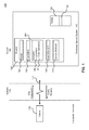
FIG. 1 illustrates the general structure of a client/server database system 100 suitable for implementing embodiments. (Specific modifications to thesystem 100 for implementing other embodiments are described in subsequent sections below.) As shown, thesystem 100 comprises one or more client computing device(s) 110 connected to aserver 130 via anetwork 120. Specifically, the client computing device(s) 110 comprise one or more standalone terminals connected to a Database Management System 140 ("DBMS") using aconventional network 120. In an exemplary embodiment, the terminals may themselves comprise a plurality of standalone workstations, dumb terminals, or the like, or comprise personal computers (PCs). Typically, such units would operate under a client operating system, such as a Microsoft® Windows, Unix, Apple®, etc., client operating system - The
database server system 130, which comprises SAP® HANA® (available from SAP) in an exemplary embodiment, generally operates as an independent process (i.e., independently of the client computing devices), running under a server operating system such as Microsoft® Windows NT, Windows 2000, Windows XP, Windows Vista and Windows 7 (all from Microsoft Corporation of Redmond, Wash.), UNIX (Novell), Solaris (Sun), or Linux (Red Hat). Thenetwork 120 may be any one of a number of conventional wired and/or wireless network systems, including a Local Area Network (LAN) or Wide Area Network (WAN), as is known in the art (e.g., using Ethernet, IBM Token Ring, or the like). In an embodiment, thenetwork 120 includes functionality for packaging client calls in the well-known Structured Query Language (SQL) together with any parameter information into a format (of one or more packets) suitable for transmission to thedatabase server system 140. The described computer hardware and software are presented for purposes of illustrating the basic underlying desktop and server computer components that may be employed for implementing embodiments of the present invention. For purposes of discussion, the following description will present examples in which it will be assumed that there exist multiple server instances (e.g., database server nodes) in a cluster that communicate with one or more "clients" (e.g., personal computers or mobile devices). The embodiments of the present invention, however, is not limited to any particular environment or device configuration. Instead, embodiments may be implemented in any type of system architecture or processing environment capable of supporting the methodologies presented herein. - In operation, the client computing device(s) 110 store data in, or retrieve data from, one or more source database tables 150, as shown at
FIG. 1 . Data in a relational database is stored as a series of tables, also called relations. Typically resident on theserver 130, each table itself comprises one or more "rows" or "records" (tuples) (e.g.,row 155 as shown atFIG. 1 ). A typical database will include many tables, each of which stores information about a particular type of entity. A table in a typical relational database may contain anywhere from a few rows to millions of rows. A row is divided into fields or columns; each field represents one particular attribute of the given row. A row corresponding to an employee record, for example, may include information about the employee's ID Number, Last Name and First Initial, Position, Date Hired, Social Security Number (SSN), and Salary. Each of these categories, in turn, represents a database field. In the foregoing employee table, for example, Position is one field, Date Hired is another, and so on. With this format, tables are easy for users to understand and use. Moreover, the flexibility of tables permits a user to define relationships between various items of data, as needed. Thus, a typical record includes several categories of information about an individual person, place, or thing. Each row in a table is uniquely identified by a record ID (RID), which can be used as a pointer to a given row. - Most relational databases implement a variant of the Structured Query Language (SQL), which is a language allowing users and administrators to create, manipulate, and access data stored in the database. SQL statements may be divided into two categories: data manipulation language (DML), used to read and write data; and data definition language (DDL), used to describe data and maintain the database. DML statements are also called queries. In operation, for example, the client computing device(s) 110 issue one or more SQL commands to the
server 130. SQL commands may specify, for instance, a query for retrieving particular data (i.e., data records meeting the query condition) from the database table(s) 150. In addition to retrieving the data from database server table(s) 150, theclients 110 also have the ability to issue commands to insert new rows of data records into the table(s), or to update and/or delete existing records in the table(s). - SQL statements or simply "queries" must be parsed to determine an access plan (also known as "execution plan" or "query plan") to satisfy a given query. In operation, the SQL statements received from the client(s) 110 (via network 120) are processed by the
source database engine 160 of theDBMS 140. Thesource database engine 160 itself comprises aparser 161, anormalizer 163, a compiler 165, anexecution unit 169, and access method(s) 170. Specifically, the SQL statements are passed to theparser 161 which employs conventional parsing methodology (e.g., recursive descent parsing). The parsed query is then normalized by thenormalizer 163. Normalization includes, for example, the elimination of redundant data. Additionally, thenormalizer 163 performs error checking, such as confirming that table names and column names which appear in the query are valid (e.g., are available and belong together). Finally, thenormalizer 163 can also look-up any referential integrity constraints which exist and add those to the query. - After normalization, the query is passed to the compiler 165, which includes an
optimizer 166 and acode generator 167. Theoptimizer 166 performs a cost-based analysis for formulating a query plan that is reasonably close to an optimal plan. Thecode generator 167 translates the query plan into executable form for execution. Theexecution unit 169 executes the query plan using theaccess methods 170. - In order to increase performance for processing queries or recover from crash of the database server system, a database management system, such as
DBMS 140, may replicate database tables. -
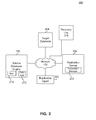
FIG. 2 is asystem 200 in which embodiments, or portions thereof, can be implemented.Source database engine 160 communicates overnetwork 120 withreplication server 206, in accordance with an embodiment. - Also in communication over
network 120 is areplication agent 202. Thereplication agent 202 facilitates the replication process by, in accordance with an embodiment, scanning atransaction log 212 for changes atsource database engine 160 and sending those changes toreplication server 206. One skilled in the relevant arts will further recognize that thenetwork 120 can be configured in a number of ways in order to achieve the same result, and the aforementioned configuration is shown by way of example, and not limitation. For instance, in accordance with an embodiment,replication agent 202 andsource database engine 160 are located in a single physical computing device or cluster of computing devices. -
Source database engine 160 includes a source database ormain index 210 and a transaction log ordelta log 212, in accordance with an embodiment. Each transactional operation, such as inserts, updates, and deletes to thesource database 210, causes a log record to be written to the transaction (delta) log 212. Each particular delta log record characterizes the change which has occurred to the source database ormain index 210 during processing of a transaction. These log records can be used, for instance, in error recovery, to restore thesource database engine 160 to a preexisting, consistent state. - In a traditional log-based replication system, changes to the
source database engine 160 are sent toreplication server 206 overnetwork 120, which then applies these changes, overnetwork 120, directly totarget database 204. As is commonly understood, thereplication server 206 starts threads, which are responsible for transferring the data from an outbound queue to thetarget database 204. - According to an embodiment,
replication server 206 is configured to identify the source database based on the query received. A source database has an internal object identifier and optionally a name associated with it. The internal object identifier is retrievable byreplication server 206 upon receiving a query request, such as a SQL query. As discussed previously, a SQL query may specify retrieving, updating or deleting particular data (i.e., data records meeting the query condition) from the source database table. Upon receiving the SQL query and updating the source database table 210,source database engine 160 sends information associated with the SQL query toreplication server 206. The information can include the internal object identifier of thesource database engine 160. The internal object identifier can identify the name and location of the source database, according to embodiments. -
Replication server 206 receives the SQL query and generates at least one symbolic link to the source database engine. The symbolic link identifies a path to thesource database engine 160 and its associatedsource database 210 anddelta log 212. A symbolic link can be a file that includes a reference tosource database engine 160 in the form of an absolute or relative path. Symbolic links operate transparently for most operations. Thus programs that read or write to files named by a symbolic link will behave as if operating directly on the target file. However, programs that need to handle symbolic links specially (e.g., backup utilities) may identify and manipulate them directly. A symbolic link includes a text string that is automatically interpreted and followed by the persistence layer of the database as a path to thesource database engine 160. The symbolic link exists independently of thesource database engine 160. -
Replication server 206 generates a replica attarget database 204 based on the generated symbolic links. The replica is a copy of thesource database engine 160 and its associated files. The replica includes at least a copy of themain index 210 and delta log 212 of thesource database engine 160. Since the replica is generated based on the symbolic links, which is essentially a pointer and soft link to thesource database engine 160, only a few data entries are written to theRecovery Log 214. Before further insertions, modifications, and deletions of data may occur, the symbolic links ofTarget Database 204 have to be materialized. During this step, the source data of 210 and 212 is read and persisted locally. However, the important aspect is that the data is not written to theRecovery Log 214. Upon inserts, modifications and deletions, the actual change to delta structures is broadcasted from theSource Database Engine 160 to allTarget Databases 204. The inserts, modifications and deletions are written into each delta log (source and target systems) as well as n times to theRecovery Log 214. According to embodiments,recovery log 214 keeps track of the symbolic links and any delta log changes. In other words, new changes are still written n times to the recovery log 214 - but the initial copy step causes minimal data volume. Accordingly, the recovery log 214 can be kept at a more manageable size and thus increase system performance. - According to an embodiment, the replicas of
target database 204 are materialized. Materialization includes the physical copying of the data fromsource database engine 160 to thetarget database 204. As noted previously, since the replicas are initially created via symbolic links, the files associated with thetarget database 204 are initially empty with the exception of the symbolic link information. During a materialization step, which may occur explicitly or take place during a delta merge of tables, the data in thesource database 160 is copied to thetarget database 204. Thus, the main index file and the delta log file (not illustrated) of thetarget database 204 will now have a mirror copy of the contents in thesource database 210 anddelta log 212. Once materialization is accomplished, the symbolic link is removed and the contents of thesource database engine 160 are deleted. - According to embodiments, if a recovery operation is performed, the
recovery log 214 is opened and read. Sincerecovery log 214 includes information associated with the symbolic link, the recovery log 214 can be used to restore the originalsource database engine 160 along with all of its replicas at the time when the copy process took place. If the replicas were changed after the copy process, these changes will also be replayed from therecovery log 214. According to embodiments, all n replicas recover from a single copy of the data. If the administrator creates a new backup after the replicas have been materialized, the complete data of all replicas will be stored n times for n replicas in the backup media. Using this mechanism, full copies of the source table will be created on all relevant servers. At the same time, the symbolic links assure that backup and recovery works without creating a large recovery log. -
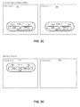
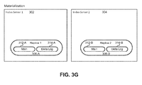
Figures 3A-3G illustrate a replication and recovery process according to embodiments. In particular,FIG. 3A illustrates an exemplary replication process and shows aserver 302 and aserver 304.Server 302 includes source database table 306 which comprises amain index 320 and adelta log 330. A replication of source database table 306 is accomplished via the generation ofsymbolic links 310. Eachsymbolic link 310 creates a soft link from the source database table 306 to its associatedreplica 308. In this example, there are 2replicas 308. Replica 308-A is created on server 302-A via symbolic links 310-A and 310-B. Similarly, replica 308-B is created onserver 304 via symbolic links 310-C and 310-D. As illustrated, eachreplica 308 can include amain index 312 and delta log 314 which mirrors the contents ofmain index 320 and delta log 330 of source database table 306. However, it is important to note that themain index 312 and delta log 314 are initially empty and only include information related to their corresponding symbolic link. The correspondingsymbolic link 310 identifies the physical location ofmain index 320 anddelta log 330, for example. -
FIG. 3B illustrates the materialization of all replicas in the system. As shown, thesymbolic links 310 and the source database table 306 are removed. Prior to removal of the source database table 306, the physical contents of the source database table 306 are copied to eachreplica 308. Additionally a count of all thesymbolic links 310 is tracked. In an embodiment, the source database table 306 is removed once a threshold is met. For example, a counter may be implemented where the max value of the counter corresponds to the number ofsymbolic links 310. The counter is decremented after eachreplica 308 is materialized. Once the counter hits zero and it is certain that allreplicas 308 have been materialized, the source database table 306 is removed. Thus, themain index 312 and delta log 314 ofreplicas 308 now include a mirror copy of the contents of thesource database 306. Upon receiving a data change request via SQL, thereplicas 308 are updated. This is illustrated inFIG. 3C . As shown, the delta logs 314 are updated with any new information that is provided via the SQL statement. Thus, any additions, deletions, or modifications to the data will be logged by the delta logs 314. -
FIGs. 3D-3G illustrate the recovery process, according to embodiments. As discussed previously, arecovery log 214 is maintained by the system and keeps track of all symbolic links and delta log changes. Thus, when a recovery operation is requested, the source database table 306 is regenerated as illustrated byFIG. 3D . Since therecovery log 214 includes the symbolic links to the source database table 306, the contents of the source database table 306 may be traced via the physical location associated with thesymbolic links 310 and the source database table 306 may be regenerated. - The next step in the recovery process is to recover all
replicas 308 andsymbolic links 310 as illustrated byFIG. 3E . Once again, therecovery log 214 is read and the system is restored to its previous state as was illustrated inFIG. 3A .FIGs. 3F and3G illustrate the materialization and recovery of the delta log entries, respectively. Thus, in this way, recovery of a database system, including allreplicas 308, can be achieved by reading arecovery log 214 which only includes information related tosymbolic links 310 and changes to thedelta log 314. -
FIG. 4 illustrates a replication-partitioning system 400, according to embodiments. Replication-partitioningsystem 400 includes a plurality ofservers 402. Eachserver 402 includes a fact partition table 404 and areplica 406 of master data. - In an embodiment, fact partition tables 404 provide the measurements, metrics, or facts of a business process. Fact partition tables 404 include numeric data such as sales figures, numbers of units, percentages, and various other additive measurements. The values of fact partition tables 404 act as independent variables by which dimensional attributes are analyzed. Fact tables are often defined by their grain. The grain of a fact table represents the most atomic level by which the facts may be defined. For example, the grain of a sales transaction fact table might be stated as "Transaction quantity by Day by Product by Store." Each record in a fact table is therefore uniquely defined by a day, product and store.
- A partitioning feature may be supported by search engines (search on plain tables, OLAP engine), within a TableUpdate operation (Insert/Update/Delete) provided by the database system. In general, components either run in a mode for a non-partitioned table or in a mode for partitioned tables. According to embodiments, the components of the database system may call a method such as Table::getPartNames() which returns the name and number of partitions present in the system for a given table. For example, in the case of a non-partitioned table, a call to Table::getPartNames() will return zero, while it will return existing part names in the case of a partitioned table. During an insert operation, the rows that shall be inserted are evaluated based on the partition specification and inserted into the right part of the table.
- To achieve replication according to embodiments, the functionality of Table::getPartNames() method is adjusted. In the case of replication, the method Table::getPartNames() is modified such that it always returns the local replica (with respect to the server on which it is being executed) as the only available partition. If there is no local replica, it returns any replica. Additionally, the insert/update/delete logic in a TableUpdate operation is modified so that it does not insert/updates/deletes a row into a single partition, but rather inserts/updates/deletes the row into all partitions / replicas.
- As discussed previously, most components of the database system call Table::getPartNames() and this returns a local replica. This serves well for most use cases. During plan generation, however, this is not sufficient. As discussed previously, a plan generation is an ordered set of steps used to access or modify information in a database. There are typically a large number of ways to execute a given query, with widely varying performance. When a query is submitted to the database, the query optimizer evaluates some of the different, correct possible plans for executing the query and returns what it considers the best alternative.
- A query plan (e.g., within the OLAP Engine) is created on an arbitrary host server (not illustrated). The plan is then executed on
relevant servers 402. A final plan must include partition names of fact partition tables 404.FIG. 4 illustrates three parts of a fact table on 3 servers. During OLAP processing, these three fact partition tables 404-A, 404-B, and 404-C are joined with the master table (not illustrated). The master table is replicated and amaster replica 406 is present on eachserver 402. Ideally the plan generation creates a plan that joins the fact partition tables 404 with the local replica of the master data. In an embodiment, on each of the 3 servers, 1/3 of the fact partition table is located (This is the case for partitioning) - whereas there are 3 copies of the entire master data table (This is the case for replication). During plan generation, it determines the replica which is local to the respective fact table part, for example it joins 404-B with 406-B. - For partitioning, the TableUpdate operation handles the insertion, modification, or deletion of data as follows: it uses a PartAllocator component to determine into which partition a row has to be inserted. For modifications and deletions of data, PartAllocator analyzes the TableUpdate operation to be performed based on the partition specification and determines which partition an update or delete has to be delegated.
- The first test case for replication is fairly trivial: Always send all TableUpdate operations to all replicas. In this way, all replicas are modified in the same way synchronously within a single transaction. There is no single point that holds any locks and there are no bottlenecks of data. A client can send its insert/update/delete to any of the servers and each server handles their respective updates. With this implementation, replication would be as efficient as partitioning. However, the load and memory consumption would be higher as all replicas are modified during each transaction.
-
FIG. 5 shows an example diagram of replication using this example test case. As illustrated, in order to propagate data changes toservers 502 hosting a replica, there are independent client requests 504-A and 504-B generated to manipulate different data. As illustrated, eachserver 502 performs its respective processing on the client request by interactions with adistributor module 506, acheck logic module 508, arowid determination module 510 and anupdate module 512. Ultimately the request is written to the index log 520 and thedelta log 530. In this scenario, a replication operation occurs almost immediately after receiving aclient request 504. For example, upon receipt of theclient request 504, the distributor module 506-A generates areplication request 514 and propagates the request to distributor module 506-B of server 502-B. At this point, eachserver 502 is individually responsible for handling the replication of data. Thus, server 502-A will send the client request 504-A to check logic module 508-A, which determines the parameters of the query. The rowid determination module 510-A then determines new rowids for new rows. Update module 512-A then performs an update of delta index log 520-A and delta log 530-A. Server 502-B performs a similar replication technique using its corresponding distributor module 506-B, check logic module 508-B, rowid determination module 510-B and update module 512-B. Thus, delta index log 520-B and delta log 530-B will also be updated. - This example test case has the drawback that several operations have to be executed independently on all replicas, which may cause unnecessary CPU consumption. Additionally, an internal rowid column is utilized to uniquely identify a row. The rowid acts as a key identifier. Using this test case, each replica would typically have different rowids for the very same row. This is a very critical aspect as some internal operations issue a query first, retrieve rowids and use the rowids to update rows. These rowids are only valid for one replica. On the other replicas, they typically identify different rows.
- Thus, embodiments provide an implementation approach which ensures that replicas have the same rowid values for a given row. This is accomplished by having a component which provides rowids for replicas. This component would exist only once and hold an exclusive lock during processing. TableUpdate performs many tasks during processing. This includes various checks and the determination of the rowid values. In the very end it applies all modifications to the delta index and writes the modifications to the
delta log 530. This is the point where replication is introduced: these net changes are replicated to all relevant replicas. In this way the load on the other servers is low as no further checks have to be applied. The net changes also include the rowid column just like all other columns. Thus the same rowid values are achieved without the need for special operations by each server. Specifically the advantage is that no additional locks for synchronizing rowid determination among the servers/replica is required. -
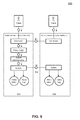
FIG. 6 illustrates this implementation, according to embodiments. As illustrated, thereplication request 602 is generated once. This is possible, because the rowid determination module onserver 604 handles the determination of rowids for all replicas. The update module is then responsible for propagating the replication request to all servers hosting a replica. Since the rowid determination is made prior to the replication request, all replicas will have identical rowid information. -
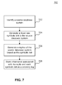
FIG. 7 is a flowchart illustrating anexemplary method 700, according to an embodiment. In one example,method 700 can be used to perform replication via a partitioning scheme. For ease of explanation,system 200 inFIG. 2 will be used to describemethod 700, butmethod 700 is not intended to be limited thereto. Themethod 700 may not occur in the order shown, or require all of the steps shown inFIG. 7 . - At
step 702, a source database table is identified. The source database table includes a main index and a delta log. For example, step 702 may be performed byreplication server 206 ofsystem 200. A source database table is identified based on a query request. As discussed previously, in an embodiment, a relational database may implement a variant of the Structured Query Language (SQL). In operation, for example, a client computing device can issue one or more SQL commands to the server hosting the source database. SQL commands may specify, for instance, a query for retrieving particular data (i.e., data records meeting the query condition) from the source database table. In addition to retrieving the data from source database table(s), the client computing device has the ability to issue commands to insert new rows of data records into the table(s), or to update and/or delete existing records in the table(s). - At
step 704, one or more symbolic links to the source database table is generated. The symbolic link identifies a path to the source database table. For example, step 704 may be performed byreplication server 206 of system 206 A symbolic link can be a file that includes a reference to the source database table in the form of an absolute or relative path. Symbolic links operate transparently for most operations. Thus, programs that read or write to files named by a symbolic link will behave as if operating directly on the target file. A symbolic link includes a text string that is automatically interpreted and followed by the persistence layer of the database as a path to the source database table. This resembles a symbolic link like in the operating system Linux. - At
step 706, a replica of the source database table is generated on the source database system and at least one target database system based on each symbolic link. The replica includes a copy of the main index and delta log of the source database. For example, step 706 may be performed byreplication server 206 ofsystem 200. The replica is a copy of the source database table and its associated files. The replica can include at least a copy of a main index file and a delta log. Since the replica is generated based on the symbolic links, which is essentially a pointer to the source database, it requires significantly less CPU consumption. This is due to the fact that all files of the replica are initially empty with the exception of the symbolic link information. - At
step 708, information associated with the replica and each symbolic link is stored in a recovery log. For example, step 708 may be performed byreplication server 206 ofsystem 200. Changes prior to the copy process to the source database are tracked and logged in the delta log of the source database table and subsequently the delta logs of all replica via the symbolic links. Additionally, a recovery log maintains information related to symbolic links and also keeps track of changes to the source database table prior to a materialization operation. Since embodiments enable the recovery log to only keep track of the symbolic links and any delta log changes, the recovery log can be kept at a relatively small and manageable size and thus increase system performance. - Various aspects of the present invention can be implemented by software, firmware, hardware, or a combination thereof.
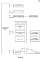
FIG. 8 illustrates anexample computer system 800 in which the present invention, or portions thereof, can be implemented as computer-readable code. For example, the method illustrated byflowchart 700 ofFIG. 7 , can be implemented usingsystem 800 -
Computer system 800 includes one or more processors, such asprocessor 804.Processor 804 can be a special purpose or a general purpose processor.Processor 804 is connected to a communication infrastructure 806 (for example, a bus or network). -
Computer system 800 also includes amain memory 808, preferably random access memory (RAM), and may also include asecondary memory 810.Secondary memory 810 may include, for example, ahard disk drive 812, aremovable storage drive 814, and/or a memory stick.Removable storage drive 814 may comprise a floppy disk drive, a magnetic tape drive, an optical disk drive, a flash memory, or the like. Theremovable storage drive 814 reads from and/or writes to aremovable storage unit 818 in a well known manner.Removable storage unit 818 may comprise a floppy disk, magnetic tape, optical disk, etc. which is read by and written to byremovable storage drive 814. As will be appreciated by persons skilled in the relevant art(s),removable storage unit 818 includes a computer usable storage medium having stored therein computer software and/or data. - In alternative implementations,
secondary memory 810 may include other similar means for allowing computer programs or other instructions to be loaded intocomputer system 800. Such means may include, for example, aremovable storage unit 822 and aninterface 820. Examples of such means may include a program cartridge and cartridge interface (such as that found in video game devices), a removable memory chip (such as an EPROM, or PROM) and associated socket, and otherremovable storage units 822 andinterfaces 820 which allow software and data to be transferred from theremovable storage unit 822 tocomputer system 800. -
Computer system 800 may also include a communications interface 824. Communications interface 824 allows software and data to be transferred betweencomputer system 800 and external devices. Communications interface 824 may include a modem, a network interface (such as an Ethernet card), a communications port, a PCMCIA slot and card, or the like. Software and data transferred via communications interface 824 are in the form of signals which may be electronic, electromagnetic, optical, or other signals capable of being received by communications interface 824. These signals are provided to communications interface 824 via acommunications path 826.Communications path 826 carries signals and may be implemented using wire or cable, fiber optics, a phone line, a cellular phone link, an RF link or other communications channels. - In this document, the terms "computer program medium" and "computer usable medium" are used to generally refer to media such as
removable storage unit 818,removable storage unit 822, and a hard disk installed inhard disk drive 812. Signals carried overcommunications path 826 can also embody the logic described herein. Computer program medium and computer usable medium can also refer to memories, such asmain memory 808 andsecondary memory 810, which can be memory semiconductors (e.g. DRAMs, etc.). These computer program products are means for providing software tocomputer system 800. - Computer programs (also called computer control logic) are stored in
main memory 808 and/orsecondary memory 810. Computer programs may also be received via communications interface 824. Such computer programs, when executed, enablecomputer system 800 to implement the present invention as discussed herein. In particular, the computer programs, when executed, enableprocessor 804 to implement the processes of the present invention, such as the method illustrated by the flowchart ofFIG. 8 . Accordingly, such computer programs represent controllers of thecomputer system 800. Where the invention is implemented using software, the software may be stored in a computer program product and loaded intocomputer system 800 usingremovable storage drive 814,interface 820,hard drive 812 or communications interface 824. - The invention is also directed to computer program products comprising software stored on any computer useable medium. Such software, when executed in one or more data processing device, causes a data processing device(s) to operate as described herein. Embodiments of the invention employ any computer useable or readable medium, known now or in the future. Examples of computer useable mediums include, but are not limited to, primary storage devices (e.g., any type of random access memory), secondary storage devices (e.g., hard drives, floppy disks, CD ROMS, ZIP disks, tapes, magnetic storage devices, optical storage devices, MEMS, nanotechnological storage device, etc.), and communication mediums (e.g., wired and wireless communications networks, local area networks, wide area networks, intranets, etc.).
- While various embodiments of the present invention have been described above, it should be understood that they have been presented by way of example only, and not limitation. It will be understood by those skilled in the relevant art(s) that various changes in form and details may be made therein without departing from the scope of the invention as defined in the appended claims. It should be understood that the invention is not limited to these examples. The invention is applicable to any elements operating as described herein. Accordingly, the breadth and scope of the present invention should not be limited by any of the above-described exemplary embodiments, but should be defined only in accordance with the following claims and their equivalents.
Claims (15)
- A method for data replication within a database environment comprising:identifying a source database table, wherein the source database table includes a main index file and a delta log file;generating one or more symbolic links to the source database table, wherein each symbolic link identifies a path to a physical location of the source database table;generating a replica of the source database table based on the symbolic links, wherein the replica includes a copy of the main index file and delta log file; andstoring information associated with the replica and the symbolic links in a recovery log.
- The method of claim 1, wherein generating one or more symbolic links comprises:identifying a unique identifier for the source database table, wherein the unique identifier indicates the physical location of the source database table within the database environment;converting the unique identifier into the path to the source database table; andgenerating a pointer to the source database table based on the path.
- The method of claim 1 or 2, further comprising:detecting a data change request, wherein the data change request indicates at least one of an add, update, and delete of data in the source database table;storing information related to the data change request in the delta log file of the replica; andupdating the recovery log with the information related to the data change request.
- The method of claim 3, further comprising:materializing the replica, wherein materializing includes propagating data from the source database table to the replica;generating a reference count based on the symbolic links;removing the symbolic links; anddeleting the source database table, when the reference count meets a predetermined threshold.
- The method of any of the preceding claims, further comprising:receiving a recovery request; andre-generating the source database table and replica based on the recovery log.
- The method of any of the preceding claims, further comprising:propagating data from the source database table to the replica, wherein a copy of the main index file and the delta log file is created for the replica.
- A system for data replication in a database system environment, the system comprising:a source database;a target database in communication with the source database; anda replication server in communication with the source database and target database, the replication server configured to:identify a source database table, wherein the source database table includes a main index file and a delta log file;generate one or more symbolic links to the source database table, wherein each symbolic link identifies a path to a physical location of the source database table;generate a replica of the source database table based on the symbolic links, wherein the replica includes a copy of the main index file and delta log file; andstore information associated with the replica and the symbolic links in a recovery log.
- The system of claim 7, wherein the replication server is further configured to perform a method as set out in any of claims 2 to 6.
- A method for data replication within a database environment comprising:partitioning, by a first server, a source database table across a plurality of additional servers, wherein the partitioning comprises generating a replica of the source database table on each of the additional servers;generating, by the first sever, a request for a name and a number of partitions residing in the database environment; andreceiving, by the first server, a replica local to the first server based on the request.
- The method of claim 9, wherein partitioning comprises:distributing different portions of the source database table across the plurality of additional servers.
- The method of claim 9 or 10, further comprising:generating an update request of the source database table; andbroadcasting the update request to the plurality of additional servers, wherein the replica for each additional server is modified based on the update request.
- The method of claim 11 wherein broadcasting comprises:acquiring a write lock of the source database table;determining a rowid value associated with the update request, wherein the rowid value determines a location for the update request;applying the update request to a delta index and delta log of the source database table; andsending the update request to replica associated with the update request with a rowid value which is the same for all replica.
- The method of any of claims 9 to 12, further comprising:generating a plan generation, wherein the plan generation identifies an ordered set of steps to access data of the source database table;executing the plan generation on the additional servers based on the plan generation, wherein executing the plan generation comprises:identifying local replica for each of the additional servers and joining the local replica with a master data table.
- A system for data replication in a database system environment having means for performing a method as set out in any of claims 9 to 13.
- A computer program product having control logic stored therein, said control logic when executed causing a processor to perform a method as set out in any of claims 1 to 6 or any of claims 9 to 13.
Applications Claiming Priority (1)
| Application Number | Priority Date | Filing Date | Title |
|---|---|---|---|
| US13/719,737 US9411866B2 (en) | 2012-12-19 | 2012-12-19 | Replication mechanisms for database environments |
Publications (2)
| Publication Number | Publication Date |
|---|---|
| EP2746971A2 true EP2746971A2 (en) | 2014-06-25 |
| EP2746971A3 EP2746971A3 (en) | 2015-01-21 |
Family
ID=49841573
Family Applications (1)
| Application Number | Title | Priority Date | Filing Date |
|---|---|---|---|
| EP13198236.5A Ceased EP2746971A3 (en) | 2012-12-19 | 2013-12-18 | Replication mechanisms for database environments |
Country Status (2)
| Country | Link |
|---|---|
| US (1) | US9411866B2 (en) |
| EP (1) | EP2746971A3 (en) |
Families Citing this family (25)
| Publication number | Priority date | Publication date | Assignee | Title |
|---|---|---|---|---|
| US10747746B2 (en) * | 2013-04-30 | 2020-08-18 | Amazon Technologies, Inc. | Efficient read replicas |
| US9110847B2 (en) * | 2013-06-24 | 2015-08-18 | Sap Se | N to M host system copy |
| US20160100004A1 (en) | 2014-10-06 | 2016-04-07 | International Business Machines Corporation | Data replication across servers |
| JP6337741B2 (en) * | 2014-10-31 | 2018-06-06 | 富士通株式会社 | Control program, control device, control method, and database system |
| US10185632B2 (en) | 2014-11-25 | 2019-01-22 | Sap Se | Data synchronization with minimal table lock duration in asynchronous table replication |
| US9959306B2 (en) | 2015-06-12 | 2018-05-01 | International Business Machines Corporation | Partition-based index management in hadoop-like data stores |
| US10628393B2 (en) | 2015-06-24 | 2020-04-21 | International Business Machines Corporation | Generating data tables |
| US10482076B2 (en) | 2015-08-14 | 2019-11-19 | Sap Se | Single level, multi-dimension, hash-based table partitioning |
| US11023538B2 (en) * | 2015-08-25 | 2021-06-01 | International Business Machines Corporation | System and methods for dynamic generation of object storage datasets from existing file datasets |
| US20170123676A1 (en) * | 2015-11-04 | 2017-05-04 | HGST Netherlands B.V. | Reference Block Aggregating into a Reference Set for Deduplication in Memory Management |
| CN106933698B (en) | 2015-12-29 | 2021-05-28 | 伊姆西Ip控股有限责任公司 | Method and device for storage system |
| US10108632B2 (en) * | 2016-05-02 | 2018-10-23 | Google Llc | Splitting and moving ranges in a distributed system |
| US11481321B2 (en) | 2017-03-27 | 2022-10-25 | Sap Se | Asynchronous garbage collection in parallel transaction system without locking |
| US10282127B2 (en) | 2017-04-20 | 2019-05-07 | Western Digital Technologies, Inc. | Managing data in a storage system |
| KR101936787B1 (en) * | 2017-05-24 | 2019-01-14 | (주)선재소프트 | Method for database replication and System for database replication |
| US10809928B2 (en) | 2017-06-02 | 2020-10-20 | Western Digital Technologies, Inc. | Efficient data deduplication leveraging sequential chunks or auxiliary databases |
| US10503608B2 (en) | 2017-07-24 | 2019-12-10 | Western Digital Technologies, Inc. | Efficient management of reference blocks used in data deduplication |
| US11615113B2 (en) * | 2017-11-03 | 2023-03-28 | International Business Machines Corporation | Net change mirroring optimization across transactions in replication environment |
| US10860612B2 (en) * | 2018-04-19 | 2020-12-08 | Sap Se | Parallel replication across formats |
| KR102303895B1 (en) * | 2020-03-12 | 2021-09-23 | (주)선재소프트 | Database Replication System With Improved Database Replication |
| CN111597257A (en) * | 2020-05-09 | 2020-08-28 | 远光软件股份有限公司 | Database synchronization method and device, storage medium and terminal |
| CN112100147A (en) * | 2020-07-27 | 2020-12-18 | 杭州玳数科技有限公司 | Method and system for realizing real-time acquisition from Bilog to HIVE based on Flink |
| US11675809B2 (en) * | 2021-03-02 | 2023-06-13 | International Business Machines Corporation | Replicating data changes using multiple storage devices and tracking records of pending data changes stored on the storage devices |
| US11853286B2 (en) * | 2021-09-21 | 2023-12-26 | Sap Se | Dynamic deployment of multiple database systems with data reduction |
| US20230401229A1 (en) * | 2022-06-13 | 2023-12-14 | Snowflake Inc. | Replication of unstructured staged data between database deployments |
Family Cites Families (8)
| Publication number | Priority date | Publication date | Assignee | Title |
|---|---|---|---|---|
| US7149761B2 (en) * | 2001-11-13 | 2006-12-12 | Tadpole Technology Plc | System and method for managing the synchronization of replicated version-managed databases |
| JP3705222B2 (en) * | 2002-02-06 | 2005-10-12 | 日本電気株式会社 | Path setting method, communication network using the same, and node device |
| US20050278277A1 (en) * | 2004-05-27 | 2005-12-15 | International Business Machines Corporation | Method and apparatus for propogating tables while preserving foreign key integrity |
| US8135763B1 (en) * | 2005-09-30 | 2012-03-13 | Emc Corporation | Apparatus and method for maintaining a file system index |
| US7870172B1 (en) * | 2005-12-22 | 2011-01-11 | Network Appliance, Inc. | File system having a hybrid file system format |
| US8112396B2 (en) * | 2006-06-07 | 2012-02-07 | Emc Corporation | Backup and recovery of integrated linked databases |
| US20080027998A1 (en) * | 2006-07-27 | 2008-01-31 | Hitachi, Ltd. | Method and apparatus of continuous data protection for NAS |
| US7885938B1 (en) * | 2008-02-27 | 2011-02-08 | Symantec Corporation | Techniques for granular recovery of data from local and remote storage |
-
2012
- 2012-12-19 US US13/719,737 patent/US9411866B2/en active Active
-
2013
- 2013-12-18 EP EP13198236.5A patent/EP2746971A3/en not_active Ceased
Non-Patent Citations (1)
| Title |
|---|
| None |
Also Published As
| Publication number | Publication date |
|---|---|
| US9411866B2 (en) | 2016-08-09 |
| EP2746971A3 (en) | 2015-01-21 |
| US20140172794A1 (en) | 2014-06-19 |
Similar Documents
| Publication | Publication Date | Title |
|---|---|---|
| US9411866B2 (en) | Replication mechanisms for database environments | |
| US11429641B2 (en) | Copying data changes to a target database | |
| KR102307371B1 (en) | Data replication and data failover within the database system | |
| US10042910B2 (en) | Database table re-partitioning using two active partition specifications | |
| US10055440B2 (en) | Database table re-partitioning using trigger-based capture and replay | |
| CN107835983B (en) | Backup and restore in distributed databases using consistent database snapshots | |
| US10585876B2 (en) | Providing snapshot isolation to a database management system | |
| US8589357B2 (en) | Techniques for automatically tracking and archiving transactional data changes | |
| US6161109A (en) | Accumulating changes in a database management system by copying the data object to the image copy if the data object identifier of the data object is greater than the image identifier of the image copy | |
| US9639542B2 (en) | Dynamic mapping of extensible datasets to relational database schemas | |
| US8296269B2 (en) | Apparatus and method for read consistency in a log mining system | |
| US10866865B1 (en) | Storage system journal entry redaction | |
| US10866968B1 (en) | Compact snapshots of journal-based storage systems | |
| CN112969996A (en) | Tracking intermediate changes in database data | |
| US20210334257A1 (en) | Pageable hash index for document store | |
| US11176004B2 (en) | Test continuous log replay | |
| US8452730B2 (en) | Archiving method and system | |
| US20230229645A1 (en) | Schema management for journal-based storage systems | |
| Schönig | Mastering PostgreSQL 12: Advanced techniques to build and administer scalable and reliable PostgreSQL database applications | |
| US11106698B2 (en) | Multi-master with ownership transfer | |
| Zhu | Towards Automated Online Schema Evolution | |
| US11687564B2 (en) | Continuous real-time masked database replication | |
| US11467926B2 (en) | Enhanced database recovery by maintaining original page savepoint versions | |
| US11599520B1 (en) | Consistency management using query restrictions in journal-based storage systems | |
| FREDRICK | GENERAL KNOWLEDGE OF SQL DATABASE |
Legal Events
| Date | Code | Title | Description |
|---|---|---|---|
| PUAI | Public reference made under article 153(3) epc to a published international application that has entered the european phase |
Free format text: ORIGINAL CODE: 0009012 |
|
| 17P | Request for examination filed |
Effective date: 20131218 |
|
| AK | Designated contracting states |
Kind code of ref document: A2 Designated state(s): AL AT BE BG CH CY CZ DE DK EE ES FI FR GB GR HR HU IE IS IT LI LT LU LV MC MK MT NL NO PL PT RO RS SE SI SK SM TR |
|
| AX | Request for extension of the european patent |
Extension state: BA ME |
|
| RAP1 | Party data changed (applicant data changed or rights of an application transferred) |
Owner name: SAP SE |
|
| PUAL | Search report despatched |
Free format text: ORIGINAL CODE: 0009013 |
|
| AK | Designated contracting states |
Kind code of ref document: A3 Designated state(s): AL AT BE BG CH CY CZ DE DK EE ES FI FR GB GR HR HU IE IS IT LI LT LU LV MC MK MT NL NO PL PT RO RS SE SI SK SM TR |
|
| AX | Request for extension of the european patent |
Extension state: BA ME |
|
| RIC1 | Information provided on ipc code assigned before grant |
Ipc: G06F 17/30 20060101AFI20141218BHEP |
|
| R17P | Request for examination filed (corrected) |
Effective date: 20150716 |
|
| RBV | Designated contracting states (corrected) |
Designated state(s): AL AT BE BG CH CY CZ DE DK EE ES FI FR GB GR HR HU IE IS IT LI LT LU LV MC MK MT NL NO PL PT RO RS SE SI SK SM TR |
|
| 17Q | First examination report despatched |
Effective date: 20151218 |
|
| STAA | Information on the status of an ep patent application or granted ep patent |
Free format text: STATUS: THE APPLICATION HAS BEEN REFUSED |
|
| 18R | Application refused |
Effective date: 20170714 |