EP2744442B1 - Vibration compensation system for power toothbrushes - Google Patents
Vibration compensation system for power toothbrushes Download PDFInfo
- Publication number
- EP2744442B1 EP2744442B1 EP12798378.1A EP12798378A EP2744442B1 EP 2744442 B1 EP2744442 B1 EP 2744442B1 EP 12798378 A EP12798378 A EP 12798378A EP 2744442 B1 EP2744442 B1 EP 2744442B1
- Authority
- EP
- European Patent Office
- Prior art keywords
- housing
- spring
- appliance
- toothbrush
- rotor
- Prior art date
- Legal status (The legal status is an assumption and is not a legal conclusion. Google has not performed a legal analysis and makes no representation as to the accuracy of the status listed.)
- Active
Links
Images

Classifications
-
- A—HUMAN NECESSITIES
- A61—MEDICAL OR VETERINARY SCIENCE; HYGIENE
- A61C—DENTISTRY; APPARATUS OR METHODS FOR ORAL OR DENTAL HYGIENE
- A61C17/00—Devices for cleaning, polishing, rinsing or drying teeth, teeth cavities or prostheses; Saliva removers; Dental appliances for receiving spittle
- A61C17/16—Power-driven cleaning or polishing devices
- A61C17/22—Power-driven cleaning or polishing devices with brushes, cushions, cups, or the like
- A61C17/32—Power-driven cleaning or polishing devices with brushes, cushions, cups, or the like reciprocating or oscillating
- A61C17/34—Power-driven cleaning or polishing devices with brushes, cushions, cups, or the like reciprocating or oscillating driven by electric motor
-
- A—HUMAN NECESSITIES
- A61—MEDICAL OR VETERINARY SCIENCE; HYGIENE
- A61C—DENTISTRY; APPARATUS OR METHODS FOR ORAL OR DENTAL HYGIENE
- A61C17/00—Devices for cleaning, polishing, rinsing or drying teeth, teeth cavities or prostheses; Saliva removers; Dental appliances for receiving spittle
- A61C17/16—Power-driven cleaning or polishing devices
- A61C17/20—Power-driven cleaning or polishing devices using ultrasonics
-
- A—HUMAN NECESSITIES
- A61—MEDICAL OR VETERINARY SCIENCE; HYGIENE
- A61C—DENTISTRY; APPARATUS OR METHODS FOR ORAL OR DENTAL HYGIENE
- A61C17/00—Devices for cleaning, polishing, rinsing or drying teeth, teeth cavities or prostheses; Saliva removers; Dental appliances for receiving spittle
- A61C17/16—Power-driven cleaning or polishing devices
- A61C17/22—Power-driven cleaning or polishing devices with brushes, cushions, cups, or the like
- A61C17/225—Handles or details thereof
-
- F—MECHANICAL ENGINEERING; LIGHTING; HEATING; WEAPONS; BLASTING
- F16—ENGINEERING ELEMENTS AND UNITS; GENERAL MEASURES FOR PRODUCING AND MAINTAINING EFFECTIVE FUNCTIONING OF MACHINES OR INSTALLATIONS; THERMAL INSULATION IN GENERAL
- F16F—SPRINGS; SHOCK-ABSORBERS; MEANS FOR DAMPING VIBRATION
- F16F15/00—Suppression of vibrations in systems; Means or arrangements for avoiding or reducing out-of-balance forces, e.g. due to motion
- F16F15/02—Suppression of vibrations of non-rotating, e.g. reciprocating systems; Suppression of vibrations of rotating systems by use of members not moving with the rotating systems
- F16F15/04—Suppression of vibrations of non-rotating, e.g. reciprocating systems; Suppression of vibrations of rotating systems by use of members not moving with the rotating systems using elastic means
Definitions
- This invention relates generally to power toothbrushes, and more specifically concerns a system for decreasing vibration of a handle portion of the toothbrush during operation of the toothbrush.
- a resonant drive system typically comprises a mechanical mass/spring arrangement driven by an actuator. In operation, the resonant mass and spring exchange mechanical energy back and forth to produce a brushing force which is significantly larger than the actuator force itself.
- the stator portion of the actuator and/or the resonant spring within the handle are mechanically attached in any way to the housing of the toothbrush, such as for mounting purposes, the resulting reaction torque provided by the mass/spring action will act on the toothbrush housing, resulting in a vibration of the handle, the vibration being typically large enough to be noticeable and in some cases producing discomfort for the user, with at least some of the actuator energy being dissipated in the hand of the user.
- US 2008/0028547 A1 discloses a power toothbrush, which has a rotating brushhead movement, includes a housing with a motor mounted therein having an armature which in operation rotates through an arc of predetermined magnitude.
- the toothbrush also includes a brushhead mounted on a shaft which is connected to an output mass.
- a spring assembly couples the armature to the output mass, the spring assembly including two spring portions with a node point therebetween, wherein when the armature rotates, the brushhead moves in an opposite direction.
- the frequency of the movement of the armature is set equal to the resonant frequency of the spring coupling system and the output assembly.
- EP 2246009 A1 discloses an oscillatory system for a motorized drive unit for the generation of a rotary oscillatory movement having a first component and a second component able to oscillate with respect to one another around an axis of oscillation.
- the oscillatory system has at least two elongate spring elements which are elastic at least in the direction of the rotary oscillatory movement and which each have two fastening points spaced apart from one another, with one respective fastening point being connected to the first oscillatory component, one respective fastening point being connected to the second oscillatory component and the connection line of the fastening points of at least one spring element and the connection line of the fastening points of at least one other spring element intersecting at an angle of intersection.
- DE 1907693 discloses a mass spring mechanism for reducing the vibrations induced by the electric motor of a small personal care appliance, such as a shaver, a toothbrush, etc.
- the mass spring mechanism comprises a subdued mass connected via spring means to the stator and which is stimulated by the reaction moments in phase and in phase opposition with the anchor.
- DE 10355446 A1 discloses an electric motor for an electrical small-scale unit.
- Said electric motor comprises at least one oscillatory motor component, a magnet arrangement comprising at least one permanent magnet, and a coil for producing a magnetic field that generates a force for stimulating a linear oscillatory movement during interaction with the magnetic arrangement.
- the electric motor is characterised in that a torque for stimulating a rotary oscillatory movement is also generated during the interaction of the magnetic field produced by the coil and the magnet arrangement.
- US 5378153 A discloses a dental hygiene apparatus which includes a body portion from one end of which extends an elongated resonator arm.
- the arm is mounted for oscillating action about a torsion pin, by means of a electromagnet in the body acting in combination with two permanent magnets which are mounted on the rear end of the resonator arm.
- On the forward end of the resonator arm is mounted a set of bristles.
- the arm is driven such that the tips of the bristles operate within ranges of amplitude and frequency to produce a bristle tip velocity greater than 1.5 meters per second, producing a significant cleansing effect beyond the tips of the bristles.
- a power toothbrush appliance comprising a handle with a first toothbrush housing portion containing a power actuator which includes a stator having a first moment of inertia, and a handle rotor portion, wherein the actuator in operation generates torque for driving the handle rotor portion, and wherein the stator and the handle rotor portion move in opposing directions during operation of the appliance, the appliance further including a first spring element or assembly having a first spring constant connecting the stator to the first housing portion or element fixed to the housing; and a brushhead assembly, wherein the brushhead assembly comprises a brushhead shaft having a bristle member at a distal end thereof for cleaning of teeth, and a brushhead rotor portion with a connecting rotor interface portion at a proximal end thereof for removably connecting the brushhead rotor portion to the handle rotor portion, wherein the handle rotor portion and the brushhead assembly form an appliance rotor having a second moment of inertia; a second toothbrush housing portion configured to mate with the first
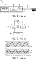
- a conventional power toothbrush 10, shown in Figure 1 with a resonant drive actuator system will include a handle 12 and a brushhead assembly 14, with a bristle portion 16 on the forward end thereof.
- the brushhead assembly 14 includes a spindle or neck member 17 which forms a rotor portion 18 of the actuator.
- the actuator also includes a stator portion 20.
- the stator is driven by a battery, with electronics control, shown generally together at 21. As indicated above, this arrangement results in a vibration being transmitted to the handle 12.
- FIG. 2 shows a source (T act ) of torque for actuator 22, driving the stator/rotor arrangement.
- Stator 20 has a mass moment of inertia J s while rotor 18 has a mass moment of inertia J r .
- Rotor 18 is connected to the stator 20 by a spring 24, designated k sr , which is the resilient part of the mass spring system of the resonant drive system, while the stator is mechanically connected to the housing 26, which has a mass moment of inertia J h .
- J h includes the mass of the electronics and the battery, respectively, while J r also includes the mass of the bristle portion of the toothbrush.
- the rotor 18 oscillates with a frequency and an amplitude to produce a cleansing action on the teeth.
- the vibration of the rotor spindle
- the movement of the stator designated at line 32
- Housing 26 experiences a significant vibration, as shown by line 34.
- the vibration of the rotor with its relatively large amplitude, is 180° out of phase with the vibration of the housing 34, while the small vibration of the stator is in phase with the vibration of the housing.
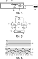
- FIG. 4 shows a simplified representation of the present vibration compensation arrangement, including a housing (handle) 38, a stator 40, and a rotor 42, which includes a spindle, with a bristle portion 44 at the forward end thereof.
- a spring 46 is fixed (fixedly attached) to both the stator 40 and the housing (handle) 38, while a spring 48 is fixed between rotor 42 and the housing 38.
- the spring constants K sh and K rh of springs 46 and 48, respectively, are selected to have the same ratio as the mass moments of inertia of the stator and rotor, respectively. This results in the net torque on the housing being zero, i.e. no vibration to the housing.
- Figure 5 is a schematic representation of the system of Figure 4 , including a source of torque 52, stator 54, rotor 56 and housing 58.
- Spring 60 connects the stator 54 and the housing 58, while spring 62 connects rotor 56 and the housing 58.
- Spring 64 connects the stator and the rotor.
- J s , J r and J h represent the mass moments of inertia for the stator, rotor and housing while k sh , and k rh represent the spring constants of springs 60 and 62.
- the rotor and the stator have opposing movements/oscillations; their respective torques therefore oppose each other relative to any action on the housing.
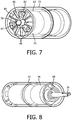
- FIG. 7 shows a first embodiment of the vibration compensation system.
- the figures show a cylindrical housing 72, a stator 74 and a rotor 76.
- the stator and the rotor are selected to provide an effective rotation of a drive shaft or neck to which a bristle member is attached.
- Figure 7 shows the spring connection between the stator and the housing.
- three pin protrusions 82-82 extend out from the rear end surface 84 of the stator 74.
- the spring connection comprises three separate leaf springs 86-86, one associated with each pin.
- the springs are plastic, although they could be metal as well. They are flexible, and are generally shaped in the form of a "W".
- Figure 8 shows the opposing end of the article, with the rotor portion of the actuator shown at 76.
- a spring 88 in the embodiment shown has a spiral shape and extends between the housing and the rotor, to both of which the spring is fixedly attached.
- the thickness of the spring is 0.3-0.4 mm if it is plastic.
- the spring would typically be thinner if it was made out of metal.
- the spring connections can be made in various ways, including welding or gluing, among others.
- stator spring may be a leaf spring, used as the suspension for the actuator within the housing, extending between the stator and the housing.
- the rotor (spindle) spring may be a leaf spring extending parallel with the housing between a member secured to the spindle and a protrusion extending a small distance inwardly from the housing.
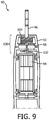
- Figure 9 shows a cut-away view of another embodiment, shown generally at 90.
- the embodiment includes a housing 92, a stator 94 and a rotor 96. At the end of the rotor a brushhead (not shown) is typically mounted.
- Rotor 96 extends from the stator through a mounting disc 98, which is mounted fixedly to the housing 92.
- a single spring 100 accomplishes both the spring fixed connection between the stator and the housing and the rotor and the housing.
- the single spring extends from the stator 94, then a single turn section to a groove in mounting disc 98, then a five turn section to rotor 96.
- the single-turn section 102 of spring 100 functions as the stator spring, between the stator and the housing, while the five-turn section 104 functions as the rotor spring, between the rotor and the housing.
- ratio of the spring constants (ratio of the stator spring section 102 and the rotor spring section 104) is the same or approximately the same as the ratio of moments of inertia of the stator and rotor sections. This results in a net torque of zero to the housing.
- the net torque remains close to zero over a range of spring constant ratios, i.e. the two ratios need not be identical to have the desired result of zero torque.
- the matched ratio arrangement is also not affected by load, i.e. use of the appliance on the teeth. Since under load there is no vibration transmitted to the handle, that portion of the actuation energy is applied to the teeth, resulting in additional energy for cleaning and resulting in improved efficiency of the toothbrush.
- the present matched ratio arrangement has a dual advantageous effect, i.e. it reduces/eliminates vibration of the handle, resulting in increased comfort for the user, and also increases the efficiency, i.e. the cleaning effectiveness, of the appliance.
- the stator must be able to move relative to the housing in both axial and tangential directions.
- the cross section of the spring windings is rectangular, with the windings in the two spring ends being oriented 90° to each other so that the single spring can be wound from one rectangular wire.
- such a cross section provides another degree of freedom, enabling the stiffness in the tangential spring direction to be independent of the stiffness in the axial spring direction.
- the axial stiffness correlates with b 2 h 2 so that the orientation of the cross-section of the windings is not relevant.
- the tangential stiffness correlates with bh 3 , so that a change in the orientation of the cross-section of the winding results in a change in the stiffness ratio of the spring.
- the axial stiffness and the tangential stiffness can be scaled relative to each other, with the axial stiffness varying in accordance with diameter D, while the tangential stiffness varies with D 3 . In this way, the axial spring stiffness and the tangential spring stiffness, combined with the mass and moment of inertia can be tuned to the desired resonance frequency ratio.
- the axial and tangential stiffness ratio is determined from the ratio of each mass and moment of inertia, with the axial ratio being 1:2.5 and the tangential ratio being 1:10.
- the b/h ratio is 0.5.
- the total stiffness, together with the rotor mass/moment of inertia determines the resonant frequency in both directions.
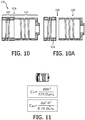
- Figure 10 shows a single spring 110 embodiment, where left side winding 112 (one winding) is connected to the stator while the right side winding 114 (2.5 windings), with the cross-section thereof being rotated 90°, is connected to the output shaft (not shown).
- the midportion 118 of the single spring 110 is connected to the housing (not shown).
- the winding arrangement of Figure 10 can be separated into two pieces, (as shown in Figure 10A ). This arrangement enables a head/handle interface at a break point 120.
- spring portion 122 being part of the brushhead assembly, spring portion 122 can be adjusted to accommodate other mass properties of the entire replacement part, while still giving the same vibration compensation effect when attached to the handle.
- the other spring portion 118 remains with the handle.
- Figure 12 includes a portion of a housing 130 of the appliance, an actuator stator 132 and a rotor/shaft 136 on which a brushhead assembly can be mounted.
- the actuator is supported by bearings 138, 140 located outside both ends of the actuator, the bearings being connected to the housing 130.
- the bearings 138 and 140 carry the user load from the brush to the handle, bearing the brushing force applied by the user.
- the front bearing 140 is positioned in a circular mount 141 which is connected to the housing.
- the shaft 136 is supported by actuator bearings 146 and 148.
- the spring suspension assembly connecting the stator and the rotor to the housing is represented at 150.
- Figures 13 and 14 show in more detail the spring assembly system.
- the spring assembly 152 is arranged so that the brushhead assembly 154 is simply fitted onto and removed from shaft 156.
- Spring portion 152 is unitary, connected in one part 160 to stator 162 and housing 164 through fixed mount element 165, while the other spring part 166 is connected to the rotor 156 and the housing 164 through mount element 165.
- Figure 14 shows an alternative arrangement, wherein the forward end 170 of the housing and fixed housing mount 172, containing a spring section 174 and a brushhead assembly 176, is detachable from the remainder 180 of the appliance through a connection interface 178A and 178B.
- a spring section 182 connects the stator 184 to the housing mount 186.
Landscapes
- Health & Medical Sciences (AREA)
- Life Sciences & Earth Sciences (AREA)
- General Health & Medical Sciences (AREA)
- Veterinary Medicine (AREA)
- Public Health (AREA)
- Animal Behavior & Ethology (AREA)
- Epidemiology (AREA)
- Dentistry (AREA)
- Engineering & Computer Science (AREA)
- General Engineering & Computer Science (AREA)
- Physics & Mathematics (AREA)
- Mechanical Engineering (AREA)
- Acoustics & Sound (AREA)
- Aviation & Aerospace Engineering (AREA)
- Brushes (AREA)
Description
- This invention relates generally to power toothbrushes, and more specifically concerns a system for decreasing vibration of a handle portion of the toothbrush during operation of the toothbrush.
- Many power toothbrushes use a resonant drive system, so that they can run efficiently at frequencies which have proven effective in cleaning of teeth, e.g. in the range of 200-300 Hz. A resonant drive system typically comprises a mechanical mass/spring arrangement driven by an actuator. In operation, the resonant mass and spring exchange mechanical energy back and forth to produce a brushing force which is significantly larger than the actuator force itself.
- However, if the stator portion of the actuator and/or the resonant spring within the handle are mechanically attached in any way to the housing of the toothbrush, such as for mounting purposes, the resulting reaction torque provided by the mass/spring action will act on the toothbrush housing, resulting in a vibration of the handle, the vibration being typically large enough to be noticeable and in some cases producing discomfort for the user, with at least some of the actuator energy being dissipated in the hand of the user.
- Various solutions have been attempted to resolve or at least decrease this effect. One solution is to increase the mass moment of inertia of the housing (handle); however, due to the typically small diameter handles, any added mass to the handle will not significantly increase its mass moment of inertia. Hence there will be little effect on vibration by adding mass. Another solution is the use of a nodal spring arrangement, in which a spring is connected to the housing at a spring node. However, this arrangement is often structurally complex and further, the stator portion of the actuator is still connected to the handle, resulting in continuing vibration of the handle.
-
US 2008/0028547 A1 discloses a power toothbrush, which has a rotating brushhead movement, includes a housing with a motor mounted therein having an armature which in operation rotates through an arc of predetermined magnitude. The toothbrush also includes a brushhead mounted on a shaft which is connected to an output mass. A spring assembly couples the armature to the output mass, the spring assembly including two spring portions with a node point therebetween, wherein when the armature rotates, the brushhead moves in an opposite direction. The frequency of the movement of the armature is set equal to the resonant frequency of the spring coupling system and the output assembly. -
EP 2246009 A1 discloses an oscillatory system for a motorized drive unit for the generation of a rotary oscillatory movement having a first component and a second component able to oscillate with respect to one another around an axis of oscillation. The oscillatory system has at least two elongate spring elements which are elastic at least in the direction of the rotary oscillatory movement and which each have two fastening points spaced apart from one another, with one respective fastening point being connected to the first oscillatory component, one respective fastening point being connected to the second oscillatory component and the connection line of the fastening points of at least one spring element and the connection line of the fastening points of at least one other spring element intersecting at an angle of intersection. -
DE 1907693 discloses a mass spring mechanism for reducing the vibrations induced by the electric motor of a small personal care appliance, such as a shaver, a toothbrush, etc. The mass spring mechanism comprises a subdued mass connected via spring means to the stator and which is stimulated by the reaction moments in phase and in phase opposition with the anchor. -
DE 10355446 A1 discloses an electric motor for an electrical small-scale unit. Said electric motor comprises at least one oscillatory motor component, a magnet arrangement comprising at least one permanent magnet, and a coil for producing a magnetic field that generates a force for stimulating a linear oscillatory movement during interaction with the magnetic arrangement. The electric motor is characterised in that a torque for stimulating a rotary oscillatory movement is also generated during the interaction of the magnetic field produced by the coil and the magnet arrangement. -
US 5378153 A discloses a dental hygiene apparatus which includes a body portion from one end of which extends an elongated resonator arm. The arm is mounted for oscillating action about a torsion pin, by means of a electromagnet in the body acting in combination with two permanent magnets which are mounted on the rear end of the resonator arm. On the forward end of the resonator arm is mounted a set of bristles. The arm is driven such that the tips of the bristles operate within ranges of amplitude and frequency to produce a bristle tip velocity greater than 1.5 meters per second, producing a significant cleansing effect beyond the tips of the bristles. - Accordingly, it is desirable to have a resonant drive arrangement to a power toothbrush which significantly reduces or eliminates vibration of the toothbrush handle during operation.
- A power toothbrush appliance, comprising a handle with a first toothbrush housing portion containing a power actuator which includes a stator having a first moment of inertia, and a handle rotor portion, wherein the actuator in operation generates torque for driving the handle rotor portion, and wherein the stator and the handle rotor portion move in opposing directions during operation of the appliance, the appliance further including a first spring element or assembly having a first spring constant connecting the stator to the first housing portion or element fixed to the housing; and a brushhead assembly, wherein the brushhead assembly comprises a brushhead shaft having a bristle member at a distal end thereof for cleaning of teeth, and a brushhead rotor portion with a connecting rotor interface portion at a proximal end thereof for removably connecting the brushhead rotor portion to the handle rotor portion, wherein the handle rotor portion and the brushhead assembly form an appliance rotor having a second moment of inertia; a second toothbrush housing portion configured to mate with the first toothbrush housing portion in response to the brushhead assembly being connected to the handle, the first and second toothbrush housing portions defining an appliance housing; and a second spring element or assembly having a second spring constant between and connected to the brushhead rotor portion and the second housing portion or an element fixed to the second housing portion, wherein a ratio of the first and second spring constants is sufficiently similar to a ratio of the first and second moments of inertia that, responsive to when the brushhead assembly is connected to the handle, there is substantially no resulting torque transmitted to the appliance housing during operation of the power toothbrush appliance and hence substantially no vibration of the appliance housing during operation of the power toothbrush appliance.
-
Figure 1 is a cross-sectional view showing a simplified power toothbrush drive arrangement involving a stator and a rotor. -
Figure 2 is a diagram showing the various parts of the power toothbrush ofFigure 1 and the electrical and mechanical connections therebetween. -
Figure 3 is a diagram showing the movement of the housing, the stator and the rotor portions ofFigure 1 , respectively. -
Figure 4 is a diagram showing the drive arrangement described herein for reducing vibration of the handle during operation of the power toothbrush. -
Figure 5 is a diagram showing the connections between the elements of the drive arrangement ofFigure 4 . -
Figure 6 is a vibration diagram showing the movement of the rotor, the stator and the housing portions with the arrangement described herein. -
Figures 7 and 8 show schematic views of one embodiment of the present drive arrangement for a power toothbrush. -
Figure 9 shows a cut-away view of another embodiment of the present drive arrangement. -
Figures 10 and 10A are cross-sectional diagrams showing two variations of a spring arrangement. -
Figure 11 shows a pictorial view of one of the variations ofFigure 10 and formulas of spring stiffness for axial and tangential directions. -
Figure 12 is a cross-sectional diagram of a power toothbrush with actuator with a spring compensation assembly. -
Figure 13 is a cross-sectional diagram of a portion of a power toothbrush with one spring compensation system. -
Figure 14 is a cross-sectional diagram of a portion of a power toothbrush with another spring compensation system. - As discussed above, a
conventional power toothbrush 10, shown inFigure 1 with a resonant drive actuator system will include a handle 12 and abrushhead assembly 14, with abristle portion 16 on the forward end thereof. Thebrushhead assembly 14 includes a spindle orneck member 17 which forms arotor portion 18 of the actuator. The actuator also includes astator portion 20. The stator is driven by a battery, with electronics control, shown generally together at 21. As indicated above, this arrangement results in a vibration being transmitted to the handle 12. - The vibration effect for the actuator system of
Figure 1 is shown inFigures 2 and 3. Figure 2 shows a source (Tact) of torque foractuator 22, driving the stator/rotor arrangement.Stator 20 has a mass moment of inertia J s whilerotor 18 has a mass moment of inertia J r . Rotor 18 is connected to thestator 20 by a spring 24, designated k sr , which is the resilient part of the mass spring system of the resonant drive system, while the stator is mechanically connected to thehousing 26, which has a mass moment of inertia J h . J h includes the mass of the electronics and the battery, respectively, while J r also includes the mass of the bristle portion of the toothbrush. - In resulting operation, the
rotor 18 oscillates with a frequency and an amplitude to produce a cleansing action on the teeth. Referring toFigure 3 , the vibration of the rotor (spindle) is shown atline 30 inFigure 3 , while the movement of the stator, designated atline 32, remains relatively quiet.Housing 26, however, experiences a significant vibration, as shown byline 34. The vibration of the rotor, with its relatively large amplitude, is 180° out of phase with the vibration of thehousing 34, while the small vibration of the stator is in phase with the vibration of the housing. - In the present arrangement, shown and described herein, the reaction of torque from the stator is compensated by a second reaction torque from the rotor. As indicated above, this is possible because the stator and the rotor move in operation in opposite directions.
Figure 4 shows a simplified representation of the present vibration compensation arrangement, including a housing (handle) 38, astator 40, and arotor 42, which includes a spindle, with abristle portion 44 at the forward end thereof. Aspring 46 is fixed (fixedly attached) to both thestator 40 and the housing (handle) 38, while aspring 48 is fixed betweenrotor 42 and thehousing 38. The spring constants K sh and K rh ofsprings -
Figure 5 is a schematic representation of the system ofFigure 4 , including a source oftorque 52,stator 54,rotor 56 andhousing 58.Spring 60 connects thestator 54 and thehousing 58, whilespring 62 connectsrotor 56 and thehousing 58.Spring 64 connects the stator and the rotor. J s , J r and J h represent the mass moments of inertia for the stator, rotor and housing while k sh , and k rh represent the spring constants ofsprings 

Figure 6 , which shows rotor movement represented byline 64 and stator movement byline 66, opposite relative to the rotor. The result is a lack of vibration to the housing, as shown byline 68. - A first embodiment of the vibration compensation system is shown in
Figures 7 and 8 . The figures show acylindrical housing 72, astator 74 and arotor 76. The stator and the rotor are selected to provide an effective rotation of a drive shaft or neck to which a bristle member is attached.Figure 7 shows the spring connection between the stator and the housing. In this particular arrangement, three pin protrusions 82-82 extend out from therear end surface 84 of thestator 74. The spring connection comprises three separate leaf springs 86-86, one associated with each pin. In the embodiment shown, the springs are plastic, although they could be metal as well. They are flexible, and are generally shaped in the form of a "W". -
Figure 8 shows the opposing end of the article, with the rotor portion of the actuator shown at 76. Aspring 88 in the embodiment shown has a spiral shape and extends between the housing and the rotor, to both of which the spring is fixedly attached. The thickness of the spring is 0.3-0.4 mm if it is plastic. The spring would typically be thinner if it was made out of metal. The spring connections can be made in various ways, including welding or gluing, among others. - The two springs could also have an additional function. For instance, the stator spring may be a leaf spring, used as the suspension for the actuator within the housing, extending between the stator and the housing. The rotor (spindle) spring may be a leaf spring extending parallel with the housing between a member secured to the spindle and a protrusion extending a small distance inwardly from the housing.
-
Figure 9 shows a cut-away view of another embodiment, shown generally at 90. The embodiment includes ahousing 92, astator 94 and arotor 96. At the end of the rotor a brushhead (not shown) is typically mounted.Rotor 96 extends from the stator through a mountingdisc 98, which is mounted fixedly to thehousing 92. In this embodiment, asingle spring 100 accomplishes both the spring fixed connection between the stator and the housing and the rotor and the housing. The single spring extends from thestator 94, then a single turn section to a groove in mountingdisc 98, then a five turn section torotor 96. The single-turn section 102 ofspring 100 functions as the stator spring, between the stator and the housing, while the five-turn section 104 functions as the rotor spring, between the rotor and the housing. - The important consideration again is that the ratio of the spring constants (ratio of the
stator spring section 102 and the rotor spring section 104) is the same or approximately the same as the ratio of moments of inertia of the stator and rotor sections. This results in a net torque of zero to the housing. - While an exact ratio match will produce a zero net torque, the net torque remains close to zero over a range of spring constant ratios, i.e. the two ratios need not be identical to have the desired result of zero torque. The matched ratio arrangement is also not affected by load, i.e. use of the appliance on the teeth. Since under load there is no vibration transmitted to the handle, that portion of the actuation energy is applied to the teeth, resulting in additional energy for cleaning and resulting in improved efficiency of the toothbrush. Hence, the present matched ratio arrangement has a dual advantageous effect, i.e. it reduces/eliminates vibration of the handle, resulting in increased comfort for the user, and also increases the efficiency, i.e. the cleaning effectiveness, of the appliance.
- In some arrangements, the stator must be able to move relative to the housing in both axial and tangential directions. In one design, the cross section of the spring windings is rectangular, with the windings in the two spring ends being oriented 90° to each other so that the single spring can be wound from one rectangular wire. Functionally, such a cross section provides another degree of freedom, enabling the stiffness in the tangential spring direction to be independent of the stiffness in the axial spring direction. According to
Figure 11 , the axial stiffness correlates with b2 h2 so that the orientation of the cross-section of the windings is not relevant. The tangential stiffness, however, correlates with bh3, so that a change in the orientation of the cross-section of the winding results in a change in the stiffness ratio of the spring. The axial stiffness and the tangential stiffness, respectively, can be scaled relative to each other, with the axial stiffness varying in accordance with diameter D, while the tangential stiffness varies with D3. In this way, the axial spring stiffness and the tangential spring stiffness, combined with the mass and moment of inertia can be tuned to the desired resonance frequency ratio. - The axial and tangential stiffness ratio is determined from the ratio of each mass and moment of inertia, with the axial ratio being 1:2.5 and the tangential ratio being 1:10. The b/h ratio is 0.5. The total stiffness, together with the rotor mass/moment of inertia determines the resonant frequency in both directions.
-
Figure 10 shows asingle spring 110 embodiment, where left side winding 112 (one winding) is connected to the stator while the right side winding 114 (2.5 windings), with the cross-section thereof being rotated 90°, is connected to the output shaft (not shown). Themidportion 118 of thesingle spring 110 is connected to the housing (not shown). The winding arrangement ofFigure 10 can be separated into two pieces, (as shown inFigure 10A ). This arrangement enables a head/handle interface at abreak point 120. With thereplacement spring portion 122 being part of the brushhead assembly,spring portion 122 can be adjusted to accommodate other mass properties of the entire replacement part, while still giving the same vibration compensation effect when attached to the handle. Theother spring portion 118 remains with the handle. - As indicated above, the actuator stator in some arrangements must be able to move relative to the housing in both axial and tangential directions. One specific arrangement is shown in
Figure 12. Figure 12 includes a portion of ahousing 130 of the appliance, anactuator stator 132 and a rotor/shaft 136 on which a brushhead assembly can be mounted. In this arrangement, the actuator is supported bybearings housing 130. Thebearings front bearing 140 is positioned in acircular mount 141 which is connected to the housing. Theshaft 136 is supported byactuator bearings -
Figures 13 and 14 show in more detail the spring assembly system. In the embodiment ofFigure 13 , thespring assembly 152 is arranged so that thebrushhead assembly 154 is simply fitted onto and removed fromshaft 156.Spring portion 152 is unitary, connected in onepart 160 tostator 162 andhousing 164 through fixedmount element 165, while theother spring part 166 is connected to therotor 156 and thehousing 164 throughmount element 165. -
Figure 14 shows an alternative arrangement, wherein theforward end 170 of the housing and fixedhousing mount 172, containing aspring section 174 and abrushhead assembly 176, is detachable from theremainder 180 of the appliance through aconnection interface spring section 182 connects thestator 184 to thehousing mount 186. - Although a preferred embodiment of the invention has been disclosed for purposes of illustration, it should be understood that various changes, modifications and substitutions may be incorporated in the embodiment without departing from the scope of the invention, which is defined by the claims which follow.
Claims (6)
- A power toothbrush appliance (10), comprising:a handle with a first toothbrush housing portion (186) containing a power actuator which includes a stator (184) having a first moment of inertia, and a handle rotor portion, wherein the actuator in operation generates torque for driving the handle rotor portion, and wherein the stator and the handle rotor portion move in opposing directions during operation of the appliance, the appliance further including a first spring element or assembly having a first spring constant connecting the stator to the first housing portion or element fixed to the housing; anda brushhead assembly, wherein the brushhead assembly comprises:a brushhead shaft (176) having a bristle member at a distal end thereof for cleaning of teeth, and a brushhead rotor portion with a connecting rotor interface portion (178A) at a proximal end thereof for removably connecting the brushhead rotor portion to the handle rotor portion, wherein the handle rotor portion and the brushhead assembly form an appliance rotor having a second moment of inertia;a second toothbrush housing portion configured to mate with the first toothbrush housing portion in response to the brushhead assembly being connected to the handle, the first and second toothbrush housing portions defining an appliance housing; anda second spring element or assembly having a second spring constant between and connected to the brushhead rotor portion and the second housing portion or an element fixed to the second housing portion, wherein a ratio of the first and second spring constants is sufficiently similar to a ratio of the first and second moments of inertia that, when the brushhead assembly is connected to the handle, there is substantially no resulting torque transmitted to the appliance housing during operation of the power toothbrush appliance (10) and hence substantially no vibration of the appliance housing during operation of the power toothbrush appliance (10).
- The power toothbrush appliance (10) of claim 1, wherein the ratio of the first and second spring constants is substantially the same as the ratio of the first and second moments of inertia.
- The power toothbrush appliance (10) of claim 1, wherein the second spring element or assembly is plastic.
- The power toothbrush appliance (10) of claim 1, wherein the second spring element or assembly is metal.
- The toothbrush appliance of claim 1, wherein the first spring element or assembly comprises a plurality of flat springs, while the second spring element or assembly is a spiral spring.
- The toothbrush appliance of claim 1, wherein the first and second spring elements are arranged to permit both axial and tangential movement of the stator relative to the housing while maintaining the compensation for vibration.
Applications Claiming Priority (2)
| Application Number | Priority Date | Filing Date | Title |
|---|---|---|---|
| US201161550578P | 2011-10-24 | 2011-10-24 | |
| PCT/IB2012/055530 WO2013061196A2 (en) | 2011-10-24 | 2012-10-12 | Vibration compensation system for power toothbrushes |
Publications (2)
| Publication Number | Publication Date |
|---|---|
| EP2744442A2 EP2744442A2 (en) | 2014-06-25 |
| EP2744442B1 true EP2744442B1 (en) | 2019-05-15 |
Family
ID=47324218
Family Applications (1)
| Application Number | Title | Priority Date | Filing Date |
|---|---|---|---|
| EP12798378.1A Active EP2744442B1 (en) | 2011-10-24 | 2012-10-12 | Vibration compensation system for power toothbrushes |
Country Status (9)
| Country | Link |
|---|---|
| US (1) | US10507092B2 (en) |
| EP (1) | EP2744442B1 (en) |
| JP (1) | JP6339016B2 (en) |
| CN (1) | CN103889367B (en) |
| BR (1) | BR112014009392A2 (en) |
| IN (1) | IN2014CN02782A (en) |
| RU (1) | RU2014120993A (en) |
| TR (1) | TR201910700T4 (en) |
| WO (1) | WO2013061196A2 (en) |
Families Citing this family (10)
| Publication number | Priority date | Publication date | Assignee | Title |
|---|---|---|---|---|
| US10849728B2 (en) | 2014-09-16 | 2020-12-01 | Koninklijke Philips N.V. | Attachment with identification for personal care appliance and method |
| CN104617732B (en) * | 2015-01-28 | 2017-04-12 | 上海携福电器有限公司 | Personal cleaning and care appliance |
| CN109688968B (en) * | 2016-09-12 | 2020-02-14 | 皇家飞利浦有限公司 | Power train assembly for personal care appliance |
| WO2018206806A1 (en) * | 2017-05-09 | 2018-11-15 | Koninklijke Philips N.V. | Vibration cancellation for personal care device |
| EP3661453A1 (en) * | 2017-07-31 | 2020-06-10 | Koninklijke Philips N.V. | Adjustable vibration absorber for a personal care device |
| US10222863B1 (en) * | 2017-09-05 | 2019-03-05 | Apple Inc. | Linear haptic actuator including field members and biasing members and related methods |
| KR102177140B1 (en) * | 2019-01-18 | 2020-11-10 | 효성중공업 주식회사 | Actuator |
| KR20220072840A (en) | 2019-09-30 | 2022-06-02 | 워어터 피이크, 인코포레이티드 | electric toothbrush |
| USD950729S1 (en) | 2019-09-30 | 2022-05-03 | Water Pik, Inc. | Toothbrush drive train |
| US20220381319A1 (en) * | 2019-10-21 | 2022-12-01 | Koninklijke Philips N.V. | A sound isolation suspension system |
Citations (5)
| Publication number | Priority date | Publication date | Assignee | Title |
|---|---|---|---|---|
| DE1907693A1 (en) * | 1968-03-01 | 1969-09-25 | Philips Nv | Device driven by an electric motor for personal care |
| US5378153A (en) * | 1992-02-07 | 1995-01-03 | Gemtech, Inc. | High performance acoustical cleaning apparatus for teeth |
| DE10355446A1 (en) * | 2003-11-27 | 2005-06-30 | Braun Gmbh | Electric motor for a small electrical appliance |
| US20080028547A1 (en) * | 2005-01-10 | 2008-02-07 | Koninklijke Philips Electronics N.V. | Nodal mounted system for driving a power appliance |
| EP2246009A1 (en) * | 2009-05-02 | 2010-11-03 | Braun GmbH | Oscillatory system for a motorized drive unit |
Family Cites Families (8)
| Publication number | Priority date | Publication date | Assignee | Title |
|---|---|---|---|---|
| DE1907693U (en) * | 1964-09-19 | 1964-12-31 | Willi Fuegener | SINGLE WHEEL TRAILER WITH UNIVERSAL JOINT. |
| JP3475949B2 (en) * | 2000-09-29 | 2003-12-10 | 松下電工株式会社 | Linear oscillator |
| JP3800094B2 (en) * | 2002-01-18 | 2006-07-19 | 松下電工株式会社 | electric toothbrush |
| US7067945B2 (en) | 2002-05-03 | 2006-06-27 | Koninklijke Philips Electronics N.V. | Apparatus for converting side-to-side driving motion to rotational motion with a spring assembly and system for tuning the spring assembly |
| US6859968B2 (en) | 2002-06-24 | 2005-03-01 | Koninklijke Philips Electronics N.V. | Nodal mounted system for driving a power appliance |
| JP4400464B2 (en) | 2005-01-19 | 2010-01-20 | パナソニック電工株式会社 | Vibration and rolling linear actuator and electric toothbrush using the same |
| EP2083746B1 (en) * | 2006-11-03 | 2018-01-10 | Koninklijke Philips N.V. | Vibration-canceling secondary resonator for use in a personal care appliance |
| US8453285B2 (en) | 2009-07-16 | 2013-06-04 | Brushpoint Innovations Inc | Vibrating toothbrush and a replaceable brush head for use with the same |
-
2012
- 2012-10-12 EP EP12798378.1A patent/EP2744442B1/en active Active
- 2012-10-12 WO PCT/IB2012/055530 patent/WO2013061196A2/en active Application Filing
- 2012-10-12 TR TR2019/10700T patent/TR201910700T4/en unknown
- 2012-10-12 JP JP2014536372A patent/JP6339016B2/en not_active Expired - Fee Related
- 2012-10-12 RU RU2014120993/14A patent/RU2014120993A/en not_active Application Discontinuation
- 2012-10-12 CN CN201280051620.7A patent/CN103889367B/en not_active Expired - Fee Related
- 2012-10-12 US US14/353,625 patent/US10507092B2/en not_active Expired - Fee Related
- 2012-10-12 IN IN2782CHN2014 patent/IN2014CN02782A/en unknown
- 2012-10-12 BR BR112014009392A patent/BR112014009392A2/en not_active IP Right Cessation
Patent Citations (5)
| Publication number | Priority date | Publication date | Assignee | Title |
|---|---|---|---|---|
| DE1907693A1 (en) * | 1968-03-01 | 1969-09-25 | Philips Nv | Device driven by an electric motor for personal care |
| US5378153A (en) * | 1992-02-07 | 1995-01-03 | Gemtech, Inc. | High performance acoustical cleaning apparatus for teeth |
| DE10355446A1 (en) * | 2003-11-27 | 2005-06-30 | Braun Gmbh | Electric motor for a small electrical appliance |
| US20080028547A1 (en) * | 2005-01-10 | 2008-02-07 | Koninklijke Philips Electronics N.V. | Nodal mounted system for driving a power appliance |
| EP2246009A1 (en) * | 2009-05-02 | 2010-11-03 | Braun GmbH | Oscillatory system for a motorized drive unit |
Also Published As
| Publication number | Publication date |
|---|---|
| TR201910700T4 (en) | 2019-08-21 |
| RU2014120993A (en) | 2015-12-10 |
| CN103889367A (en) | 2014-06-25 |
| JP6339016B2 (en) | 2018-06-06 |
| JP2014530702A (en) | 2014-11-20 |
| CN103889367B (en) | 2016-10-19 |
| WO2013061196A3 (en) | 2013-06-27 |
| IN2014CN02782A (en) | 2015-07-03 |
| US10507092B2 (en) | 2019-12-17 |
| WO2013061196A2 (en) | 2013-05-02 |
| EP2744442A2 (en) | 2014-06-25 |
| BR112014009392A2 (en) | 2017-04-18 |
| US20140259473A1 (en) | 2014-09-18 |
Similar Documents
| Publication | Publication Date | Title |
|---|---|---|
| EP2744442B1 (en) | Vibration compensation system for power toothbrushes | |
| US5613259A (en) | High frequency electric toothbrush | |
| US7730569B2 (en) | Disposable head portion for a nodally mounted rotating toothbrush | |
| US7732952B1 (en) | Oscillatory motors and devices incorporating them | |
| EP2685617B1 (en) | Linear motor and electric device with linear motor | |
| JP5176891B2 (en) | Actuator and electric toothbrush using the same | |
| US9301822B2 (en) | Vibration-canceling secondary resonator for use in a personal care appliance | |
| EP2845566B1 (en) | Mechanically driven resonant drive train for a power toothbrush | |
| EP2515792B1 (en) | A mechanical drive train with a motor and an eccentric for a resonant power toothbrush | |
| EP3734808B1 (en) | Personal hygiene device | |
| JP2009045202A (en) | Electric toothbrush and replacement brush | |
| JP6613694B2 (en) | Actuator and electric hairdressing beauty instrument | |
| WO2023088824A1 (en) | Drivetrain assemblies for generating sweeping motion and power tapping motion |
Legal Events
| Date | Code | Title | Description |
|---|---|---|---|
| PUAI | Public reference made under article 153(3) epc to a published international application that has entered the european phase |
Free format text: ORIGINAL CODE: 0009012 |
|
| 17P | Request for examination filed |
Effective date: 20140320 |
|
| AK | Designated contracting states |
Kind code of ref document: A2 Designated state(s): AL AT BE BG CH CY CZ DE DK EE ES FI FR GB GR HR HU IE IS IT LI LT LU LV MC MK MT NL NO PL PT RO RS SE SI SK SM TR |
|
| DAX | Request for extension of the european patent (deleted) | ||
| STAA | Information on the status of an ep patent application or granted ep patent |
Free format text: STATUS: EXAMINATION IS IN PROGRESS |
|
| 17Q | First examination report despatched |
Effective date: 20170222 |
|
| GRAP | Despatch of communication of intention to grant a patent |
Free format text: ORIGINAL CODE: EPIDOSNIGR1 |
|
| STAA | Information on the status of an ep patent application or granted ep patent |
Free format text: STATUS: GRANT OF PATENT IS INTENDED |
|
| INTG | Intention to grant announced |
Effective date: 20181205 |
|
| RIN1 | Information on inventor provided before grant (corrected) |
Inventor name: BAX, PIETER JOHANNES Inventor name: BOSMAN, FRANCISCUS JOZEF Inventor name: WESTRUP, GEERT HENDRIK |
|
| GRAS | Grant fee paid |
Free format text: ORIGINAL CODE: EPIDOSNIGR3 |
|
| GRAA | (expected) grant |
Free format text: ORIGINAL CODE: 0009210 |
|
| STAA | Information on the status of an ep patent application or granted ep patent |
Free format text: STATUS: THE PATENT HAS BEEN GRANTED |
|
| AK | Designated contracting states |
Kind code of ref document: B1 Designated state(s): AL AT BE BG CH CY CZ DE DK EE ES FI FR GB GR HR HU IE IS IT LI LT LU LV MC MK MT NL NO PL PT RO RS SE SI SK SM TR |
|
| REG | Reference to a national code |
Ref country code: CH Ref legal event code: EP Ref country code: GB Ref legal event code: FG4D |
|
| REG | Reference to a national code |
Ref country code: DE Ref legal event code: R096 Ref document number: 602012060175 Country of ref document: DE |
|
| REG | Reference to a national code |
Ref country code: IE Ref legal event code: FG4D |
|
| REG | Reference to a national code |
Ref country code: NL Ref legal event code: MP Effective date: 20190515 |
|
| REG | Reference to a national code |
Ref country code: LT Ref legal event code: MG4D |
|
| PG25 | Lapsed in a contracting state [announced via postgrant information from national office to epo] |
Ref country code: NO Free format text: LAPSE BECAUSE OF FAILURE TO SUBMIT A TRANSLATION OF THE DESCRIPTION OR TO PAY THE FEE WITHIN THE PRESCRIBED TIME-LIMIT Effective date: 20190815 Ref country code: FI Free format text: LAPSE BECAUSE OF FAILURE TO SUBMIT A TRANSLATION OF THE DESCRIPTION OR TO PAY THE FEE WITHIN THE PRESCRIBED TIME-LIMIT Effective date: 20190515 Ref country code: PT Free format text: LAPSE BECAUSE OF FAILURE TO SUBMIT A TRANSLATION OF THE DESCRIPTION OR TO PAY THE FEE WITHIN THE PRESCRIBED TIME-LIMIT Effective date: 20190915 Ref country code: ES Free format text: LAPSE BECAUSE OF FAILURE TO SUBMIT A TRANSLATION OF THE DESCRIPTION OR TO PAY THE FEE WITHIN THE PRESCRIBED TIME-LIMIT Effective date: 20190515 Ref country code: SE Free format text: LAPSE BECAUSE OF FAILURE TO SUBMIT A TRANSLATION OF THE DESCRIPTION OR TO PAY THE FEE WITHIN THE PRESCRIBED TIME-LIMIT Effective date: 20190515 Ref country code: AL Free format text: LAPSE BECAUSE OF FAILURE TO SUBMIT A TRANSLATION OF THE DESCRIPTION OR TO PAY THE FEE WITHIN THE PRESCRIBED TIME-LIMIT Effective date: 20190515 Ref country code: NL Free format text: LAPSE BECAUSE OF FAILURE TO SUBMIT A TRANSLATION OF THE DESCRIPTION OR TO PAY THE FEE WITHIN THE PRESCRIBED TIME-LIMIT Effective date: 20190515 Ref country code: HR Free format text: LAPSE BECAUSE OF FAILURE TO SUBMIT A TRANSLATION OF THE DESCRIPTION OR TO PAY THE FEE WITHIN THE PRESCRIBED TIME-LIMIT Effective date: 20190515 Ref country code: LT Free format text: LAPSE BECAUSE OF FAILURE TO SUBMIT A TRANSLATION OF THE DESCRIPTION OR TO PAY THE FEE WITHIN THE PRESCRIBED TIME-LIMIT Effective date: 20190515 |
|
| PG25 | Lapsed in a contracting state [announced via postgrant information from national office to epo] |
Ref country code: RS Free format text: LAPSE BECAUSE OF FAILURE TO SUBMIT A TRANSLATION OF THE DESCRIPTION OR TO PAY THE FEE WITHIN THE PRESCRIBED TIME-LIMIT Effective date: 20190515 Ref country code: GR Free format text: LAPSE BECAUSE OF FAILURE TO SUBMIT A TRANSLATION OF THE DESCRIPTION OR TO PAY THE FEE WITHIN THE PRESCRIBED TIME-LIMIT Effective date: 20190816 Ref country code: BG Free format text: LAPSE BECAUSE OF FAILURE TO SUBMIT A TRANSLATION OF THE DESCRIPTION OR TO PAY THE FEE WITHIN THE PRESCRIBED TIME-LIMIT Effective date: 20190815 Ref country code: LV Free format text: LAPSE BECAUSE OF FAILURE TO SUBMIT A TRANSLATION OF THE DESCRIPTION OR TO PAY THE FEE WITHIN THE PRESCRIBED TIME-LIMIT Effective date: 20190515 |
|
| REG | Reference to a national code |
Ref country code: AT Ref legal event code: MK05 Ref document number: 1132537 Country of ref document: AT Kind code of ref document: T Effective date: 20190515 |
|
| PG25 | Lapsed in a contracting state [announced via postgrant information from national office to epo] |
Ref country code: SK Free format text: LAPSE BECAUSE OF FAILURE TO SUBMIT A TRANSLATION OF THE DESCRIPTION OR TO PAY THE FEE WITHIN THE PRESCRIBED TIME-LIMIT Effective date: 20190515 Ref country code: EE Free format text: LAPSE BECAUSE OF FAILURE TO SUBMIT A TRANSLATION OF THE DESCRIPTION OR TO PAY THE FEE WITHIN THE PRESCRIBED TIME-LIMIT Effective date: 20190515 Ref country code: CZ Free format text: LAPSE BECAUSE OF FAILURE TO SUBMIT A TRANSLATION OF THE DESCRIPTION OR TO PAY THE FEE WITHIN THE PRESCRIBED TIME-LIMIT Effective date: 20190515 Ref country code: AT Free format text: LAPSE BECAUSE OF FAILURE TO SUBMIT A TRANSLATION OF THE DESCRIPTION OR TO PAY THE FEE WITHIN THE PRESCRIBED TIME-LIMIT Effective date: 20190515 Ref country code: RO Free format text: LAPSE BECAUSE OF FAILURE TO SUBMIT A TRANSLATION OF THE DESCRIPTION OR TO PAY THE FEE WITHIN THE PRESCRIBED TIME-LIMIT Effective date: 20190515 Ref country code: DK Free format text: LAPSE BECAUSE OF FAILURE TO SUBMIT A TRANSLATION OF THE DESCRIPTION OR TO PAY THE FEE WITHIN THE PRESCRIBED TIME-LIMIT Effective date: 20190515 |
|
| REG | Reference to a national code |
Ref country code: DE Ref legal event code: R097 Ref document number: 602012060175 Country of ref document: DE |
|
| PG25 | Lapsed in a contracting state [announced via postgrant information from national office to epo] |
Ref country code: SM Free format text: LAPSE BECAUSE OF FAILURE TO SUBMIT A TRANSLATION OF THE DESCRIPTION OR TO PAY THE FEE WITHIN THE PRESCRIBED TIME-LIMIT Effective date: 20190515 Ref country code: IT Free format text: LAPSE BECAUSE OF FAILURE TO SUBMIT A TRANSLATION OF THE DESCRIPTION OR TO PAY THE FEE WITHIN THE PRESCRIBED TIME-LIMIT Effective date: 20190515 |
|
| RAP2 | Party data changed (patent owner data changed or rights of a patent transferred) |
Owner name: KONINKLIJKE PHILIPS N.V. |
|
| PLBE | No opposition filed within time limit |
Free format text: ORIGINAL CODE: 0009261 |
|
| STAA | Information on the status of an ep patent application or granted ep patent |
Free format text: STATUS: NO OPPOSITION FILED WITHIN TIME LIMIT |
|
| 26N | No opposition filed |
Effective date: 20200218 |
|
| PG25 | Lapsed in a contracting state [announced via postgrant information from national office to epo] |
Ref country code: PL Free format text: LAPSE BECAUSE OF FAILURE TO SUBMIT A TRANSLATION OF THE DESCRIPTION OR TO PAY THE FEE WITHIN THE PRESCRIBED TIME-LIMIT Effective date: 20190515 |
|
| PG25 | Lapsed in a contracting state [announced via postgrant information from national office to epo] |
Ref country code: SI Free format text: LAPSE BECAUSE OF FAILURE TO SUBMIT A TRANSLATION OF THE DESCRIPTION OR TO PAY THE FEE WITHIN THE PRESCRIBED TIME-LIMIT Effective date: 20190515 Ref country code: MC Free format text: LAPSE BECAUSE OF FAILURE TO SUBMIT A TRANSLATION OF THE DESCRIPTION OR TO PAY THE FEE WITHIN THE PRESCRIBED TIME-LIMIT Effective date: 20190515 |
|
| REG | Reference to a national code |
Ref country code: CH Ref legal event code: PL |
|
| PG25 | Lapsed in a contracting state [announced via postgrant information from national office to epo] |
Ref country code: LU Free format text: LAPSE BECAUSE OF NON-PAYMENT OF DUE FEES Effective date: 20191012 Ref country code: LI Free format text: LAPSE BECAUSE OF NON-PAYMENT OF DUE FEES Effective date: 20191031 Ref country code: CH Free format text: LAPSE BECAUSE OF NON-PAYMENT OF DUE FEES Effective date: 20191031 |
|
| REG | Reference to a national code |
Ref country code: BE Ref legal event code: MM Effective date: 20191031 |
|
| PG25 | Lapsed in a contracting state [announced via postgrant information from national office to epo] |
Ref country code: BE Free format text: LAPSE BECAUSE OF NON-PAYMENT OF DUE FEES Effective date: 20191031 |
|
| PG25 | Lapsed in a contracting state [announced via postgrant information from national office to epo] |
Ref country code: IE Free format text: LAPSE BECAUSE OF NON-PAYMENT OF DUE FEES Effective date: 20191012 |
|
| PGFP | Annual fee paid to national office [announced via postgrant information from national office to epo] |
Ref country code: DE Payment date: 20201030 Year of fee payment: 9 Ref country code: FR Payment date: 20201027 Year of fee payment: 9 Ref country code: GB Payment date: 20201027 Year of fee payment: 9 |
|
| PG25 | Lapsed in a contracting state [announced via postgrant information from national office to epo] |
Ref country code: CY Free format text: LAPSE BECAUSE OF FAILURE TO SUBMIT A TRANSLATION OF THE DESCRIPTION OR TO PAY THE FEE WITHIN THE PRESCRIBED TIME-LIMIT Effective date: 20190515 |
|
| PG25 | Lapsed in a contracting state [announced via postgrant information from national office to epo] |
Ref country code: IS Free format text: LAPSE BECAUSE OF FAILURE TO SUBMIT A TRANSLATION OF THE DESCRIPTION OR TO PAY THE FEE WITHIN THE PRESCRIBED TIME-LIMIT Effective date: 20190915 |
|
| PG25 | Lapsed in a contracting state [announced via postgrant information from national office to epo] |
Ref country code: MT Free format text: LAPSE BECAUSE OF FAILURE TO SUBMIT A TRANSLATION OF THE DESCRIPTION OR TO PAY THE FEE WITHIN THE PRESCRIBED TIME-LIMIT Effective date: 20190515 Ref country code: HU Free format text: LAPSE BECAUSE OF FAILURE TO SUBMIT A TRANSLATION OF THE DESCRIPTION OR TO PAY THE FEE WITHIN THE PRESCRIBED TIME-LIMIT; INVALID AB INITIO Effective date: 20121012 |
|
| PGFP | Annual fee paid to national office [announced via postgrant information from national office to epo] |
Ref country code: TR Payment date: 20210929 Year of fee payment: 10 |
|
| REG | Reference to a national code |
Ref country code: DE Ref legal event code: R119 Ref document number: 602012060175 Country of ref document: DE |
|
| GBPC | Gb: european patent ceased through non-payment of renewal fee |
Effective date: 20211012 |
|
| PG25 | Lapsed in a contracting state [announced via postgrant information from national office to epo] |
Ref country code: MK Free format text: LAPSE BECAUSE OF FAILURE TO SUBMIT A TRANSLATION OF THE DESCRIPTION OR TO PAY THE FEE WITHIN THE PRESCRIBED TIME-LIMIT Effective date: 20190515 |
|
| PG25 | Lapsed in a contracting state [announced via postgrant information from national office to epo] |
Ref country code: GB Free format text: LAPSE BECAUSE OF NON-PAYMENT OF DUE FEES Effective date: 20211012 Ref country code: DE Free format text: LAPSE BECAUSE OF NON-PAYMENT OF DUE FEES Effective date: 20220503 |
|
| PG25 | Lapsed in a contracting state [announced via postgrant information from national office to epo] |
Ref country code: FR Free format text: LAPSE BECAUSE OF NON-PAYMENT OF DUE FEES Effective date: 20211031 |