EP2744193B1 - Embedded audio routing switcher - Google Patents
Embedded audio routing switcher Download PDFInfo
- Publication number
- EP2744193B1 EP2744193B1 EP14160139.3A EP14160139A EP2744193B1 EP 2744193 B1 EP2744193 B1 EP 2744193B1 EP 14160139 A EP14160139 A EP 14160139A EP 2744193 B1 EP2744193 B1 EP 2744193B1
- Authority
- EP
- European Patent Office
- Prior art keywords
- audio
- signals
- embedded
- time division
- video
- Prior art date
- Legal status (The legal status is an assumption and is not a legal conclusion. Google has not performed a legal analysis and makes no representation as to the accuracy of the status listed.)
- Active
Links
- 230000005236 sound signal Effects 0.000 claims description 44
- 239000011159 matrix material Substances 0.000 claims description 37
- 238000000034 method Methods 0.000 claims description 12
- 238000012546 transfer Methods 0.000 claims description 8
- 230000005540 biological transmission Effects 0.000 claims 1
- 230000006870 function Effects 0.000 description 9
- 238000010586 diagram Methods 0.000 description 8
- 238000012545 processing Methods 0.000 description 4
- 238000013461 design Methods 0.000 description 3
- 230000009467 reduction Effects 0.000 description 3
- 244000025254 Cannabis sativa Species 0.000 description 2
- 238000004519 manufacturing process Methods 0.000 description 2
- 230000008569 process Effects 0.000 description 2
- 238000013459 approach Methods 0.000 description 1
- 230000003139 buffering effect Effects 0.000 description 1
- 238000001514 detection method Methods 0.000 description 1
- 239000000284 extract Substances 0.000 description 1
- 238000012986 modification Methods 0.000 description 1
- 230000004048 modification Effects 0.000 description 1
- 230000007704 transition Effects 0.000 description 1
- 230000000007 visual effect Effects 0.000 description 1
Images


Classifications
-
- H—ELECTRICITY
- H04—ELECTRIC COMMUNICATION TECHNIQUE
- H04N—PICTORIAL COMMUNICATION, e.g. TELEVISION
- H04N5/00—Details of television systems
- H04N5/222—Studio circuitry; Studio devices; Studio equipment
- H04N5/262—Studio circuits, e.g. for mixing, switching-over, change of character of image, other special effects ; Cameras specially adapted for the electronic generation of special effects
- H04N5/268—Signal distribution or switching
-
- H—ELECTRICITY
- H04—ELECTRIC COMMUNICATION TECHNIQUE
- H04N—PICTORIAL COMMUNICATION, e.g. TELEVISION
- H04N7/00—Television systems
- H04N7/04—Systems for the transmission of one television signal, i.e. both picture and sound, by a single carrier
Definitions
- the present invention generally relates to switching systems and more particularly to systems and methods including a serial digital video router switching matrix with full embedded audio switching capability, which is independent from the video switching.
- Routing switchers may also be called signal selectors, audio /video (AV) selectors or simply routers.
- a standard routing switcher may have multiple video and audio signals from a number of sources, such as Videotape Recorders, Media Servers, Satellite Receivers, etc. connected to the routers inputs.
- the router's output or outputs can go to one or more destinations, such as Videotape Recorders, Video/Audio Mixers, Video/Audio Monitors, etc. Which input connects to which output(s) may be selected by a user with the push of a button, without disconnecting/reconnecting audio and video cables.
- a single program may require switching to a plurality of different channels or stations.
- the audio that is embedded may not be appropriate for each channel. For example, a different language may be needed or a dubbed version of the audio track may be required. In these situations, the audio output must be switched independently from the video.
- a routing switcher may be employed to perform this task.
- the advantages of switching video with embedded audio include a substantial reduction of switching hardware and system cabling when compared with separate audio switching matrices.
- Many modern devices such as video tape recorders, media servers and master control switchers support video inputs and outputs with embedded audio.
- WO2006/042207 A1 describes conventional signal switching infrastructure for digital video signals that uses a video cross-point switching matrix and an audio cross-point switching matrix for routing digital audio and digital video signals.
- a principal disadvantage is that conventional serial digital video switching matrices do not permit independent switching of the embedded audio streams within the video signal. This makes it difficult to combine, e.g., the video from input #1 with the audio from input #2 at an output of the switching matrix. In many facilities, especially production/post production, or where multi-channel and/or multilingual audio must be considered, this limitation has dictated the use of a separate audio switching infrastructure.
- an apparatus includes a separator for selectively separating audio from input signals including video with audio, a switcher for selectively transferring the input signals to at least one output, a multiplexed path for sending the separated audio signal to the at least one output, the at least one output being configured for selectively directing the input signals and separated audio signals.
- an apparatus in another example, includes at least one input board configured to receive digital input signals, the digital input signals including video with embedded audio, the at least one input board including: a de-embed module configured to d-embed audio from each of the digital input signals, a time division multiplexer configured to multiplex all of the de-embedded audio to at least one output board, a crosspoint matrix configured to receive the digital input signals and transfer the digital input signals to the at least one output board, a time division multiplexed path configured to transport the de-embedded audio signals to the at least one output board separately from the digital input signals, and the at least one output board configured to route one of the digital input signals and selected de- embedded audio signals in accordance with a routing control setting.
- a de-embed module configured to d-embed audio from each of the digital input signals
- a time division multiplexer configured to multiplex all of the de-embedded audio to at least one output board
- a crosspoint matrix configured to receive the digital input signals and
- a method includes separating audio from input signals including video with audio, transferring selectively the input signals to at least one output, sending the separated audio signal to the at least one output, and selectively directing the input signals and separated audio signals with the at least one output.
- a method for routing video signals with embedded audio through a routing switcher includes receiving digital input video signals with embedded audio, de-embedding an audio portion from the digital input signals while separately maintaining the digital input signals, and time division multiplexing the audio portion of all of the digital input signals for transfer to an output stage on a time division multiplexed path.
- the digital input signals are transferred to the output stage separately from time division multiplexed audio signals.
- At least one of the digital input signals and the time division multiplexed audio signals are routed to a destination.
- the present invention provides systems and methods for fully embedded audio switching capability for a serial digital video router.
- the serial digital video router switching matrix can provide the fully embedded audio switching independently from the video switching.
- the router can be employed in high definition and/or standard definition applications.
- the present invention is described in terms of a television facility; however, the present invention is much broader and may include any audio/video system, which receives a plurality of audio and visual signals from one or more sources to be routed to one or more destinations.
- Content may be received by any method for example, delivered over a network, e.g., telephone, cable, computer, satellite, etc.
- the present invention is described in terms of a television network application; however, the concepts of the present invention may be extended to other applications, e.g., cable, satellite network, wireless and wired network types.
- FIGS. may be implemented in various forms of hardware, software or combinations thereof. Preferably, these elements are implemented in a combination of hardware and software on one or more appropriately programmed general-purpose devices, which may include a processor, memory and input/output interfaces.
- processor or “controller” should not be construed to refer exclusively to hardware capable of executing software, and may implicitly include, without limitation, digital signal processor (“DSP”) hardware, read-only memory (“ROM”) for storing software, random access memory (“RAM”), and non-volatile storage.
- DSP digital signal processor
- ROM read-only memory
- RAM random access memory
- any element expressed as a means for performing a specified function is intended to encompass any way of performing that function including, for example, a) a combination of circuit elements that performs that function or b) software in any form, including, therefore, firmware, microcode or the like, combined with appropriate circuitry for executing that software to perform the function.
- the invention as defined by such claims resides in the fact that the functionalities provided by the various recited means are combined and brought together in the manner which the claims call for. It is thus regarded that any means that can provide those functionalities are equivalent to those shown herein.
- an illustrative system 10 shows a portion of the internal circuitry for a serial digital routing switcher for a television facility.
- System 10 includes a plurality of input boards 12 and a plurality of output boards 14.
- Each input board 12 includes one or more video inputs 16.
- all inputs include embedded audio.
- Inputs 16 preferably include serial digital video (SDV) with an embedded digital audio stream 15, e.g., a stream conforming to the Audio Engineering Society/European Broadcasting Union (AES/EBU) Standard or AES for short.
- SDV serial digital video
- AES/EBU Audio Engineering Society/European Broadcasting Union
- each input board provides several functions. These functions include SDV signal processing by a processor 19.
- Signal processing may include many different processes. For example, signal detection, equalization of the stream, data re-clocking, etc.
- Integrated audio de-embedding is employed for each serial digital video (SDV) input 16.
- SDV serial digital video
- Each input board 12 de-embeds the audio (AES/EBU or simply AES) from the SDV input signal by employing a de-embed module 20.
- All the de- embedded audio signals are then combined together on one or more time division multiplexed (TDM) bit-stream(s) 24 by a time division multiplexer (TDM) 22.
- TDM bitstream(s) 24 are connected directly to video switching matrix output circuits 26 on output boards 14.
- the serial digital video signals with their embedded audio 15 are also connected to inputs of a video switching matrix 30.
- the output of the video switching matrix 30 (e.g., a serial digital video crosspoint matrix) is connected directly to a given output (output board 14) and the original embedded audio is simply passed through with the video 15'.
- the audio is selected from the TDM stream(s) 24 by a router control system and a time division demultiplexer 32 demuxes the signals and combines the video using audio embedding circuitry 34 associated with the given output.
- the desired signal may be selected using the time division demultiplexer 32 on the output board 14.
- Audio is preferably embedded in the digital video bitstream 15 in the Horizontal Ancillary Data space in accordance with the signal format standards defined by the Society of Motion Picture and Television Engineers (SMPTE). Audio is de-embedded by module 20 by selecting the desired audio channel ancillary data from the serial digital video bit stream 15, buffering the data, and reformatting as an AES/EBU digital audio bit stream. Video and audio signal selection is controlled by a routing switcher control system 52. Video and audio are usually presented to the operators as separate signal levels on the routing control panels and graphical user interfaces (e.g., control 52).
- SMPTE Society of Motion Picture and Television Engineers
- a routing selection may be made by an operator, by a program or by hardware based on operating conditions or presettings.
- a first SDV signal is received with embedded audio and a second SDV signal is received from a different source.
- the first and second signals have their audio deembedded and provided to output boards.
- the output boards can embed the audio from the first signal into the second signal and vice versa.
- the outputted first and second signals may both be able to use the audio of the original first signal, or the outputted first and second signals may both be able to use the audio of the original second signal. Since all audio streams are available any audio or combination of audio channels can be selected and output including the SDV with fully embedded audio streams. This has many advantages and provides great flexibility in selecting output hardware for optimizing the outputs of the system for entertainment value or other reasons.
- output board or stage 14 includes a TDM audio demultiplexer 32, an audio embedding circuit 34, and a serial digital video (SDV) re- clocking circuit 36.
- the SDV signal is fed from an output of the crosspoint matrix (30, FIG. 1 ) to the video input of the audio embedding circuit 34.
- the TDM audio demultiplexer 32 receives the TDM audio stream and, under the control of the routing control system 52 ( FIG. 1 ), can decode selected audio signals from the TDM audio stream and apply the audio to the audio inputs of the audio embedding circuit 34.
- the audio embedding circuit 34 is directed by the router control system 52 to pass one or more channels of the audio already embedded in the SDV signal (in cases where the audio originally associated with the video is needed), or to embed one or more audio signals from the TDM audio demultiplexer 32 (in cases where different audio signals are needed).
- the output of the audio embedding circuit 34 includes both video and one or more channels of embedded audio; this output is applied to the SDV re-clocker module 36 which extracts a clock signal from the SDV signal and uses the clock signal to re-clock the SDV signal thereby removing jitter.
- TDM time division multiplex
- the TDM bit rate is preferably compatible with the video switching matrix, in practice either the standard definition component serial digital bit rate 270Mb/s (64 audio channels) or the high definition component serial digital bit rate of 1.48Gb/s (up to 352 audio channels) should be employed. Since this scheme uses some of the video routing paths for the TDM busses, the effective matrix size may be reduced.
- FIGS. 3 and 4 show illustrative examples of modified router switch designs in accordance with the present principles.
- FIGS. 3 and 4 a Grass Valley Trinix(TM) 128x128 matrix ( FIG. 3 ) and a Grass Valley Trinix(TM) 256x256 matrix ( FIG. 4 ) are illustratively shown. These example devices show the possibility of including audio only inputs and outputs in the system, which can provide additional audio tracks to be combined with audio. Separate audio inputs/outputs may be employed with the embodiment shown in FIG. 1 as well.
- Devices 200 and 220 can include single AES/EBU (Audio Engineering Society/European Broadcasting Union) digital audio streams or they could include TDM streams including multiple audio channels such as the 270Mb/s and 1.485Gb/s streams described previously or the industry standard Multichannel Audio Digital Interface (MADI) format.
- AES/EBU Audio Engineering Society/European Broadcasting Union
- TDM streams including multiple audio channels such as the 270Mb/s and 1.485Gb/s streams described previously or the industry standard Multichannel Audio Digital Interface (MADI) format.
- MADI Multichannel Audio Digital Interface
- a router 200 includes a 128x128 wideband digital crosspoint matrix 130 that is reduced to a 124x112 matrix.
- the reduced matrix size is employed to provide TDM paths 111 through the matrix 130.
- SDV with embedded audio inputs 15 include thirty-one inputs per input board 14. Since this design includes four input boards, there are one hundred and twenty four inputs in total.
- audio only inputs or a TDM input stream 110 may be provided, e.g., one per board (4 total).
- the input 110 may include multiple audio channels such as the 270Mb/s and 1.485Gb/s streams for television.
- Time division multiplexing (22) is performed and may include the TDM input 110 as well as all of the de-embedded audio from signals 15, which is placed on paths 111 and transported through the matrix 130.
- the video with embedded audio signals 15' are also transported to the output boards 16.
- Each output board 16 includes twenty eight outputs (total 112 outputs).
- the audio outputs 110' (AES or TDM) for this system may include four per board (16 total).
- the routing (32), embedding (34) and reclocking (36) are also performed as previously described.
- a router 220 includes a 256x256 wideband digital crosspoint matrix 132 that is reduced to a 248x192 matrix.
- the reduced matrix size is employed to provide TDM paths 111 through the matrix 132.
- SDV with embedded audio inputs 15 includes thirty-one inputs per input board 14. Since this design includes eight input boards, there are two hundred and forty eight inputs in total.
- audio only inputs or a TDM input 110 may be provided, e.g., one per board (8 total).
- the input 110 may include multiple audio channels such as the 270Mb/s and 1.485Gb/s streams for television.
- Time division multiplexing (22) is performed and may include the TDM input 110 as well as all of the de-embedded audio from signals 15, which is placed on paths 111 and transported through the matrix 132.
- the video with embedded audio signals 15' are also transported to the output boards 16.
- eight output boards 16 are available. Each output board 16 includes twenty four outputs (total 192 outputs).
- the audio outputs 110' (AES or TDM) for this system may include eight per board (64 total).
- the routing (32), embedding (34) and reclocking (36) are also performed as previously described.
- the audio inputs 110 may include audio streams from any source and may be employed to provide a desired audio stream for selection by a routing control system (not shown).
- Matrixes 130 and 132 may be reduced by other amounts, as needed.
- an illustrative method for routing video signals with embedded audio through a routing switcher is depicted in accordance with one embodiment.
- digital input video signals with embedded audio or audio only signals
- These signals are preferably received using an input board having a de-embed module.
- an audio portion is de-embedded from the digital input signals while separately maintaining the digital input signals (the audio only signals are maintained as well).
- the audio portion is time division multiplexed for alt of the digital input signals for transfer to an output stage on a time division multiplexed path in block 306.
- the time division multiplexed path may include a separate bus or a path through a crosspoint matrix, where at least a portion of a crosspoint matrix is used to implement the path.
- a reduction in the matrix size may be employed to permit the time division multiplexed path through the matrix.
- the digital input signals are transferred to the output stage separately from time division multiplexed audio signals.
- the digital input signals are preferably transferred using the crosspoint matrix, and are transferred with the original embedded audio.
- the time division multiplexed audio signals are demultiplexed to provide the signal to particular destinations or to simply reproduce the audio to be re-embedded with a same or different video signal In accordance with particular requirements, if needed.
- embedding a time division multiplexed audio signal into to a digital input signal or video signal may be performed to reconstitute a video signal with new embedded audio.
- reclocking may be performed, if needed, by extracting a clock signal from the SDV signal to re-clock the SDV signal thereby removing jitter.
- an audio only input may be provided and configured to receive an audio signal or a time division multiplexed audio signal for transfer to the output stage.
- the audio only signals are available for mixing with video signals as with de-embedded audio signals.
- the audio only input may be received and employed at any point in the operation.
- at least one of the digital input signals and the time division multiplexed audio signals are routed to a destination from the output stage.
- the destination is usually selected by a routing control system, by a user, by a program, in accordance with preselected conditions, etc. For example, if an original audio stream is sent with English audio and the film is sent to a Spanish station, the Spanish audio may be preselected for a given destination from a particular output board or stage.
- the signals are routed to destinations based on a router control system or programmed selections (e.g., routing settings).
Landscapes
- Engineering & Computer Science (AREA)
- Multimedia (AREA)
- Signal Processing (AREA)
- Studio Circuits (AREA)
- Data Exchanges In Wide-Area Networks (AREA)
- Time-Division Multiplex Systems (AREA)
Description
- The present invention generally relates to switching systems and more particularly to systems and methods including a serial digital video router switching matrix with full embedded audio switching capability, which is independent from the video switching.
- Routing switchers may also be called signal selectors, audio /video (AV) selectors or simply routers. A standard routing switcher may have multiple video and audio signals from a number of sources, such as Videotape Recorders, Media Servers, Satellite Receivers, etc. connected to the routers inputs. The router's output or outputs can go to one or more destinations, such as Videotape Recorders, Video/Audio Mixers, Video/Audio Monitors, etc. Which input connects to which output(s) may be selected by a user with the push of a button, without disconnecting/reconnecting audio and video cables.
- In a television facility, a single program may require switching to a plurality of different channels or stations. In some situations, the audio that is embedded may not be appropriate for each channel. For example, a different language may be needed or a dubbed version of the audio track may be required. In these situations, the audio output must be switched independently from the video. A routing switcher may be employed to perform this task.
- When constructing a signal switching infrastructure for a television facility, a choice needs to be made to use video with embedded audio as a single switching level or to use independent audio routing matrices to switch audio separately from video. The advantages of switching video with embedded audio include a substantial reduction of switching hardware and system cabling when compared with separate audio switching matrices. Many modern devices such as video tape recorders, media servers and master control switchers support video inputs and outputs with embedded audio.
WO2006/042207 A1 describes conventional signal switching infrastructure for digital video signals that uses a video cross-point switching matrix and an audio cross-point switching matrix for routing digital audio and digital video signals. - A principal disadvantage is that conventional serial digital video switching matrices do not permit independent switching of the embedded audio streams within the video signal. This makes it difficult to combine, e.g., the video from input #1 with the audio from input #2 at an output of the switching matrix. In many facilities, especially production/post production, or where multi-channel and/or multilingual audio must be considered, this limitation has dictated the use of a separate audio switching infrastructure.
- In the past, separate audio switching infrastructures have been employed (with the attendant increase in cost, space needed, cabling and power consumption). Hybrid systems using outboard audio embedding and de-embedding devices in conjunction with serial digital video switching matrices have also been employed. This alterative is also costly and complex to implement.
- In an aspect of the invention there is provided an apparatus as set forth in claim 1. In another aspect of the invention there is provided a method as set forth in claim 7.
- In an example, an apparatus includes a separator for selectively separating audio from input signals including video with audio, a switcher for selectively transferring the input signals to at least one output, a multiplexed path for sending the separated audio signal to the at least one output, the at least one output being configured for selectively directing the input signals and separated audio signals.
- In another example, an apparatus includes at least one input board configured to receive digital input signals, the digital input signals including video with embedded audio, the at least one input board including: a de-embed module configured to d-embed audio from each of the digital input signals, a time division multiplexer configured to multiplex all of the de-embedded audio to at least one output board, a crosspoint matrix configured to receive the digital input signals and transfer the digital input signals to the at least one output board, a time division multiplexed path configured to transport the de-embedded audio signals to the at least one output board separately from the digital input signals, and the at least one output board configured to route one of the digital input signals and selected de- embedded audio signals in accordance with a routing control setting.
- In a further example, a method includes separating audio from input signals including video with audio, transferring selectively the input signals to at least one output, sending the separated audio signal to the at least one output, and selectively directing the input signals and separated audio signals with the at least one output.
- In a yet further example, a method for routing video signals with embedded audio through a routing switcher includes receiving digital input video signals with embedded audio, de-embedding an audio portion from the digital input signals while separately maintaining the digital input signals, and time division multiplexing the audio portion of all of the digital input signals for transfer to an output stage on a time division multiplexed path. The digital input signals are transferred to the output stage separately from time division multiplexed audio signals. At least one of the digital input signals and the time division multiplexed audio signals are routed to a destination.
- The advantages, nature, and various additional features of the invention will appear more fully upon consideration of the illustrative embodiments now to be described in detail in connection with accompanying drawings wherein:
-
FIG. 1 is a diagram showing an exemplary routing switcher for routing audio embedded signals in accordance with one embodiment; -
FIG. 2 is a block diagram showing an output stage in greater detail; -
FIG. 3 is a diagram showing an exemplary routing switcher for routing audio embedded signals where a crosspoint matrix has been adapted to provide a time division multiplexed path for separately transferred audio signals in accordance with another embodiment; -
FIG. 4 is a diagram showing another exemplary routing switcher for routing audio embedded signals where a crosspoint matrix has been adapted to provide a time division multiplexed path for separately transferred audio signals in accordance with another embodiment; and -
FIG. 5 is a flow diagram showing an exemplary method for routing audio embedded signals in accordance with one embodiment. - It should be understood that the drawings are for purposes of illustrating the concepts of the invention and are not necessarily the only possible configuration for illustrating the invention.
- The present invention provides systems and methods for fully embedded audio switching capability for a serial digital video router. The serial digital video router switching matrix can provide the fully embedded audio switching independently from the video switching. The router can be employed in high definition and/or standard definition applications. By providing full independent switching of the audio signals included in the serial digital video bit-streams, reduction in cost and complexity is provided and greater flexibility is achieved in selecting input and outputs for the system.
- It is to be understood that the present invention is described in terms of a television facility; however, the present invention is much broader and may include any audio/video system, which receives a plurality of audio and visual signals from one or more sources to be routed to one or more destinations. Content may be received by any method for example, delivered over a network, e.g., telephone, cable, computer, satellite, etc. The present invention is described in terms of a television network application; however, the concepts of the present invention may be extended to other applications, e.g., cable, satellite network, wireless and wired network types.
- It should be understood that the elements shown in the FIGS. may be implemented in various forms of hardware, software or combinations thereof. Preferably, these elements are implemented in a combination of hardware and software on one or more appropriately programmed general-purpose devices, which may include a processor, memory and input/output interfaces.
- The present description illustrates the principles of the present invention. It will thus be appreciated that those skilled in the art will be able to devise various arrangements that, although not explicitly described or shown herein, embody the principles of the invention and are included within its spirit and scope.
- Moreover, all statements herein reciting principles, aspects, and embodiments of the invention, as well as specific examples thereof, are intended to encompass both structural and functional equivalents thereof. Additionally, it is intended that such equivalents include both currently known equivalents as well as equivalents developed in the future, i.e., any elements developed that perform the same function, regardless of structure.
- Thus, for example, it will be appreciated by those skilled in the art that the block diagrams presented herein represent conceptual views of illustrative circuitry embodying the principles of the invention. Similarly, it will be appreciated that any flow charts, flow diagrams, state transition diagrams, pseudocode, and the like represent various processes which may be substantially represented in computer readable media and so executed by a computer or processor, whether or not such computer or processor is explicitly shown.
- The functions of the various elements shown in the figures may be provided through the use of dedicated hardware as well as hardware capable of executing software in association with appropriate software. When provided by a processor, the functions may be provided by a single dedicated processor, by a single shared processor, or by a plurality of individual processors, some of which may be shared. Moreover, explicit use of the term "processor" or "controller" should not be construed to refer exclusively to hardware capable of executing software, and may implicitly include, without limitation, digital signal processor ("DSP") hardware, read-only memory ("ROM") for storing software, random access memory ("RAM"), and non-volatile storage.
- In the claims hereof, any element expressed as a means for performing a specified function is intended to encompass any way of performing that function including, for example, a) a combination of circuit elements that performs that function or b) software in any form, including, therefore, firmware, microcode or the like, combined with appropriate circuitry for executing that software to perform the function. The invention as defined by such claims resides in the fact that the functionalities provided by the various recited means are combined and brought together in the manner which the claims call for. It is thus regarded that any means that can provide those functionalities are equivalent to those shown herein.
- Referring now in specific detail to the drawings in which like reference numerals identify similar or identical elements throughout the several views, and initially to
FIG. 1 , anillustrative system 10 shows a portion of the internal circuitry for a serial digital routing switcher for a television facility.System 10 includes a plurality ofinput boards 12 and a plurality ofoutput boards 14. Eachinput board 12 includes one ormore video inputs 16. In this example, all inputs include embedded audio.Inputs 16 preferably include serial digital video (SDV) with an embeddeddigital audio stream 15, e.g., a stream conforming to the Audio Engineering Society/European Broadcasting Union (AES/EBU) Standard or AES for short. In this example, each input board provides several functions. These functions include SDV signal processing by aprocessor 19. Signal processing may include many different processes. For example, signal detection, equalization of the stream, data re-clocking, etc. - Integrated audio de-embedding is employed for each serial digital video (SDV)
input 16. Eachinput board 12 de-embeds the audio (AES/EBU or simply AES) from the SDV input signal by employing ade-embed module 20. All the de- embedded audio signals are then combined together on one or more time division multiplexed (TDM) bit-stream(s) 24 by a time division multiplexer (TDM) 22. The TDM bitstream(s) 24 are connected directly to video switching matrix output circuits 26 onoutput boards 14. The serial digital video signals with their embeddedaudio 15 are also connected to inputs of avideo switching matrix 30. - In cases where a given output needs the video with its original embedded
audio signal 15, the output of the video switching matrix 30 (e.g., a serial digital video crosspoint matrix) is connected directly to a given output (output board 14) and the original embedded audio is simply passed through with the video 15'. In cases where a given output (output board 14) needs different audio signals which are embedded in the video signal, the audio is selected from the TDM stream(s) 24 by a router control system and atime division demultiplexer 32 demuxes the signals and combines the video usingaudio embedding circuitry 34 associated with the given output. The desired signal may be selected using thetime division demultiplexer 32 on theoutput board 14. - Audio is preferably embedded in the
digital video bitstream 15 in the Horizontal Ancillary Data space in accordance with the signal format standards defined by the Society of Motion Picture and Television Engineers (SMPTE). Audio is de-embedded bymodule 20 by selecting the desired audio channel ancillary data from the serial digitalvideo bit stream 15, buffering the data, and reformatting as an AES/EBU digital audio bit stream. Video and audio signal selection is controlled by a routingswitcher control system 52. Video and audio are usually presented to the operators as separate signal levels on the routing control panels and graphical user interfaces (e.g., control 52). This enables the operator to either select both video and audio from the same input (in which case the audio already embedded with the video is used), or the operator may select video from one input and audio from one or more alternate inputs (in which case the desired audio signals are selected from theaudio TDM stream 24 and applied to an audio embeddingcircuit 34 of the appropriate output. A routing selection may be made by an operator, by a program or by hardware based on operating conditions or presettings. - In one embodiment, a first SDV signal is received with embedded audio and a second SDV signal is received from a different source. In accordance with this embodiment, the first and second signals have their audio deembedded and provided to output boards. The output boards can embed the audio from the first signal into the second signal and vice versa. Alternately, the outputted first and second signals may both be able to use the audio of the original first signal, or the outputted first and second signals may both be able to use the audio of the original second signal. Since all audio streams are available any audio or combination of audio channels can be selected and output including the SDV with fully embedded audio streams. This has many advantages and provides great flexibility in selecting output hardware for optimizing the outputs of the system for entertainment value or other reasons.
- Referring to
FIG. 2 , output board orstage 14 includes aTDM audio demultiplexer 32, anaudio embedding circuit 34, and a serial digital video (SDV) re- clockingcircuit 36. The SDV signal is fed from an output of the crosspoint matrix (30,FIG. 1 ) to the video input of the audio embeddingcircuit 34. TheTDM audio demultiplexer 32 receives the TDM audio stream and, under the control of the routing control system 52 (FIG. 1 ), can decode selected audio signals from the TDM audio stream and apply the audio to the audio inputs of the audio embeddingcircuit 34. The audio embeddingcircuit 34 is directed by therouter control system 52 to pass one or more channels of the audio already embedded in the SDV signal (in cases where the audio originally associated with the video is needed), or to embed one or more audio signals from the TDM audio demultiplexer 32 (in cases where different audio signals are needed). The output of the audio embeddingcircuit 34 includes both video and one or more channels of embedded audio; this output is applied to theSDV re-clocker module 36 which extracts a clock signal from the SDV signal and uses the clock signal to re-clock the SDV signal thereby removing jitter. - In another embodiment, in addition to or instead of constructing a new system with purpose-built TDM paths from inputs to outputs, it is also possible to implement the present principles in existing serial digital video switching matrices. One way of doing this may include replacing conventional input and output circuits with those including audio de-embedding, embedding and time division multiplex (TDM) bussing. The TDM busses would be distributed from the input circuits to the output circuits by dedicating existing paths in a video switching matrix for the use of TDM. This results in an equivalent system to the one schematically represented in
FIG. 1 . - For the approach using existing hardware, the TDM bit rate is preferably compatible with the video switching matrix, in practice either the standard definition component serial digital bit rate 270Mb/s (64 audio channels) or the high definition component serial digital bit rate of 1.48Gb/s (up to 352 audio channels) should be employed. Since this scheme uses some of the video routing paths for the TDM busses, the effective matrix size may be reduced.
FIGS. 3 and4 show illustrative examples of modified router switch designs in accordance with the present principles. - Referring to
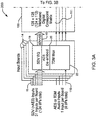
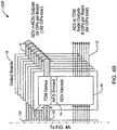
FIGS. 3 and4 , a Grass Valley Trinix(TM) 128x128 matrix (FIG. 3 ) and a Grass Valley Trinix(TM) 256x256 matrix (FIG. 4 ) are illustratively shown. These example devices show the possibility of including audio only inputs and outputs in the system, which can provide additional audio tracks to be combined with audio. Separate audio inputs/outputs may be employed with the embodiment shown inFIG. 1 as well.Devices - Referring to
FIG. 3 , arouter 200 includes a 128x128 widebanddigital crosspoint matrix 130 that is reduced to a 124x112 matrix. The reduced matrix size is employed to provideTDM paths 111 through thematrix 130. In this embodiment, SDV with embeddedaudio inputs 15 include thirty-one inputs perinput board 14. Since this design includes four input boards, there are one hundred and twenty four inputs in total. In addition, audio only inputs or aTDM input stream 110 may be provided, e.g., one per board (4 total). Theinput 110 may include multiple audio channels such as the 270Mb/s and 1.485Gb/s streams for television. - As described above, signal processing by a
processor 19 is performed and the audio is de-embedded (20). Time division multiplexing (22) is performed and may include theTDM input 110 as well as all of the de-embedded audio fromsignals 15, which is placed onpaths 111 and transported through thematrix 130. The video with embedded audio signals 15' are also transported to theoutput boards 16. In this example, fouroutput boards 16 are available. Eachoutput board 16 includes twenty eight outputs (total 112 outputs). Theaudio outputs 110' (AES or TDM) for this system may include four per board (16 total). The routing (32), embedding (34) and reclocking (36) are also performed as previously described. - Referring to
FIG. 4 , arouter 220 includes a 256x256 widebanddigital crosspoint matrix 132 that is reduced to a 248x192 matrix. The reduced matrix size is employed to provideTDM paths 111 through thematrix 132. In this embodiment, SDV with embeddedaudio inputs 15 includes thirty-one inputs perinput board 14. Since this design includes eight input boards, there are two hundred and forty eight inputs in total. In addition, audio only inputs or aTDM input 110 may be provided, e.g., one per board (8 total). Theinput 110 may include multiple audio channels such as the 270Mb/s and 1.485Gb/s streams for television. - As described above, signal processing by a
processor 19 is performed and the audio is de-embedded (20). Time division multiplexing (22) is performed and may include theTDM input 110 as well as all of the de-embedded audio fromsignals 15, which is placed onpaths 111 and transported through thematrix 132. The video with embedded audio signals 15' are also transported to theoutput boards 16. In this example, eightoutput boards 16 are available. Eachoutput board 16 includes twenty four outputs (total 192 outputs). Theaudio outputs 110' (AES or TDM) for this system may include eight per board (64 total). The routing (32), embedding (34) and reclocking (36) are also performed as previously described. InFIGS. 3 and4 , theaudio inputs 110 may include audio streams from any source and may be employed to provide a desired audio stream for selection by a routing control system (not shown).Matrixes - Referring to
FIG. 5 , an illustrative method for routing video signals with embedded audio through a routing switcher is depicted in accordance with one embodiment. Inblock 302, digital input video signals with embedded audio (or audio only signals) are received. These signals are preferably received using an input board having a de-embed module. Inblock 304, an audio portion is de-embedded from the digital input signals while separately maintaining the digital input signals (the audio only signals are maintained as well). The audio portion is time division multiplexed for alt of the digital input signals for transfer to an output stage on a time division multiplexed path inblock 306. The time division multiplexed path may include a separate bus or a path through a crosspoint matrix, where at least a portion of a crosspoint matrix is used to implement the path. A reduction in the matrix size may be employed to permit the time division multiplexed path through the matrix. - In
block 310, the digital input signals are transferred to the output stage separately from time division multiplexed audio signals. The digital input signals are preferably transferred using the crosspoint matrix, and are transferred with the original embedded audio. Inblock 312, the time division multiplexed audio signals are demultiplexed to provide the signal to particular destinations or to simply reproduce the audio to be re-embedded with a same or different video signal In accordance with particular requirements, if needed. Inblock 314, embedding a time division multiplexed audio signal into to a digital input signal or video signal may be performed to reconstitute a video signal with new embedded audio. Inblock 316, reclocking may be performed, if needed, by extracting a clock signal from the SDV signal to re-clock the SDV signal thereby removing jitter. - In
block 320, an audio only input may be provided and configured to receive an audio signal or a time division multiplexed audio signal for transfer to the output stage. The audio only signals are available for mixing with video signals as with de-embedded audio signals. The audio only input may be received and employed at any point in the operation. Inblock 322, at least one of the digital input signals and the time division multiplexed audio signals are routed to a destination from the output stage. The destination is usually selected by a routing control system, by a user, by a program, in accordance with preselected conditions, etc. For example, if an original audio stream is sent with English audio and the film is sent to a Spanish station, the Spanish audio may be preselected for a given destination from a particular output board or stage. The signals are routed to destinations based on a router control system or programmed selections (e.g., routing settings). - Having described preferred embodiments for an embedded audio routing switcher (which are intended to be illustrative and not limiting), it is noted that modifications and variations can be made by persons skilled in the art in light of the above teachings. It is therefore to be understood that changes may be made in the particular embodiments of the invention disclosed which are within the scope of the invention as outlined by the appended claims.
Claims (8)
- An apparatus (10), comprising:at least one input board (12) configured to receive digital input signals, the digital input signals each including video with embedded audio, the at least one input board including:a de-embed module (20) configured to de-embed audio signals from each of the digital input signals; anda time division multiplexer (22) configured to multiplex all of the de-embedded audio signals together prior to their transmission to at least one output board;a crosspoint matrix (130) configured to receive the digital input signals from the at least one input board and transfer the digital input signals to the at least one output board (14);a path (24) configured to transport the time division multiplexed de-embedded audio signals from the at least one input board to the at least one output board separately from the digital input signals, by using at least a portion of the crosspoint matrix (130); andthe at least one output board (14) configured to route the digital input signals and the de-embedded audio signals, the at least one output board (14) including a demultiplexer (32) configured to demultiplex the multiplexed de-embedded audio signals.
- The apparatus of claim 1, wherein the at least one input board (12) includes a processor (19) configured to equalize the digital input signals.
- The apparatus of claim 1, wherein the apparatus (10) includes a serial digital switcher configured to route television signals.
- The apparatus of claim 3, wherein the television signals include at least one of a standard definition signal and a high definition signal.
- The apparatus of claim 1, wherein the path (24) includes a bus to transport the multiplexed signal of the de-embedded audio signals.
- The apparatus of claim 1, further comprising an audio only input (110) configured to receive one of an audio signal and a time division multiplexed audio signal for transfer to the at least one output board.
- A method for routing video signals with embedded audio through a routing switcher, comprising:receiving (302) digital input video signals, each of them including video with embedded audio;de-embedding (304) audio signals from each of the digital input signals; time division multiplexing (306) the de-embedded audio signals together prior to their transfer to an output stage on a time division multiplexed path through the routing switcher using at least a portion of a crosspoint matrix to implement the path;transferring (310) the digital input signals to the output stage separately from the time division multiplexed de-embedded audio signals by using at least a portion of the crosspoint matrix (130);demultiplexing, by a demultiplexer (32) of the output stage, the time division multiplexed de-embedded audio signals androuting (322), by the output stage, the digital input signals and the de-embedded and demultiplexed time division multiplexed audio signals.
- The method as recited in claim 7, further comprising providing (320) an audio only input configured to receive one of an audio signal and a time division multiplexed audio signal for transfer to the at least one output.
Priority Applications (1)
| Application Number | Priority Date | Filing Date | Title |
|---|---|---|---|
| EP14160139.3A EP2744193B1 (en) | 2006-12-20 | 2006-12-20 | Embedded audio routing switcher |
Applications Claiming Priority (3)
| Application Number | Priority Date | Filing Date | Title |
|---|---|---|---|
| EP06847871.8A EP2103110B1 (en) | 2006-12-20 | 2006-12-20 | Embedded audio routing switcher |
| EP14160139.3A EP2744193B1 (en) | 2006-12-20 | 2006-12-20 | Embedded audio routing switcher |
| PCT/US2006/048697 WO2008079112A1 (en) | 2006-12-20 | 2006-12-20 | Embedded audio routing switcher |
Related Parent Applications (1)
| Application Number | Title | Priority Date | Filing Date |
|---|---|---|---|
| EP06847871.8A Division EP2103110B1 (en) | 2006-12-20 | 2006-12-20 | Embedded audio routing switcher |
Publications (2)
| Publication Number | Publication Date |
|---|---|
| EP2744193A1 EP2744193A1 (en) | 2014-06-18 |
| EP2744193B1 true EP2744193B1 (en) | 2018-07-04 |
Family
ID=39562787
Family Applications (2)
| Application Number | Title | Priority Date | Filing Date |
|---|---|---|---|
| EP14160139.3A Active EP2744193B1 (en) | 2006-12-20 | 2006-12-20 | Embedded audio routing switcher |
| EP06847871.8A Active EP2103110B1 (en) | 2006-12-20 | 2006-12-20 | Embedded audio routing switcher |
Family Applications After (1)
| Application Number | Title | Priority Date | Filing Date |
|---|---|---|---|
| EP06847871.8A Active EP2103110B1 (en) | 2006-12-20 | 2006-12-20 | Embedded audio routing switcher |
Country Status (6)
| Country | Link |
|---|---|
| US (3) | US8750295B2 (en) |
| EP (2) | EP2744193B1 (en) |
| JP (1) | JP4886041B2 (en) |
| CN (1) | CN101563915B (en) |
| CA (1) | CA2672418C (en) |
| WO (1) | WO2008079112A1 (en) |
Families Citing this family (46)
| Publication number | Priority date | Publication date | Assignee | Title |
|---|---|---|---|---|
| CA2463228C (en) | 2003-04-04 | 2012-06-26 | Evertz Microsystems Ltd. | Apparatus, systems and methods for packet based transmission of multiple data signals |
| US8917876B2 (en) | 2006-06-14 | 2014-12-23 | Personics Holdings, LLC. | Earguard monitoring system |
| US11450331B2 (en) | 2006-07-08 | 2022-09-20 | Staton Techiya, Llc | Personal audio assistant device and method |
| EP2044804A4 (en) | 2006-07-08 | 2013-12-18 | Personics Holdings Inc | Personal audio assistant device and method |
| WO2008079112A1 (en) | 2006-12-20 | 2008-07-03 | Thomson Licensing | Embedded audio routing switcher |
| US8917894B2 (en) | 2007-01-22 | 2014-12-23 | Personics Holdings, LLC. | Method and device for acute sound detection and reproduction |
| US8254591B2 (en) | 2007-02-01 | 2012-08-28 | Personics Holdings Inc. | Method and device for audio recording |
| US11750965B2 (en) | 2007-03-07 | 2023-09-05 | Staton Techiya, Llc | Acoustic dampening compensation system |
| WO2008124786A2 (en) | 2007-04-09 | 2008-10-16 | Personics Holdings Inc. | Always on headwear recording system |
| US11317202B2 (en) | 2007-04-13 | 2022-04-26 | Staton Techiya, Llc | Method and device for voice operated control |
| US11683643B2 (en) | 2007-05-04 | 2023-06-20 | Staton Techiya Llc | Method and device for in ear canal echo suppression |
| US10194032B2 (en) | 2007-05-04 | 2019-01-29 | Staton Techiya, Llc | Method and apparatus for in-ear canal sound suppression |
| US11856375B2 (en) | 2007-05-04 | 2023-12-26 | Staton Techiya Llc | Method and device for in-ear echo suppression |
| US10009677B2 (en) | 2007-07-09 | 2018-06-26 | Staton Techiya, Llc | Methods and mechanisms for inflation |
| US8600067B2 (en) | 2008-09-19 | 2013-12-03 | Personics Holdings Inc. | Acoustic sealing analysis system |
| US9129291B2 (en) | 2008-09-22 | 2015-09-08 | Personics Holdings, Llc | Personalized sound management and method |
| US8554350B2 (en) | 2008-10-15 | 2013-10-08 | Personics Holdings Inc. | Device and method to reduce ear wax clogging of acoustic ports, hearing aid sealing system, and feedback reduction system |
| WO2010094033A2 (en) | 2009-02-13 | 2010-08-19 | Personics Holdings Inc. | Earplug and pumping systems |
| EP2586216A1 (en) | 2010-06-26 | 2013-05-01 | Personics Holdings, Inc. | Method and devices for occluding an ear canal having a predetermined filter characteristic |
| KR20140024271A (en) | 2010-12-30 | 2014-02-28 | 암비엔즈 | Information processing using a population of data acquisition devices |
| US10356532B2 (en) | 2011-03-18 | 2019-07-16 | Staton Techiya, Llc | Earpiece and method for forming an earpiece |
| US10362381B2 (en) | 2011-06-01 | 2019-07-23 | Staton Techiya, Llc | Methods and devices for radio frequency (RF) mitigation proximate the ear |
| WO2014039026A1 (en) | 2012-09-04 | 2014-03-13 | Personics Holdings, Inc. | Occlusion device capable of occluding an ear canal |
| CN103812842A (en) * | 2012-11-14 | 2014-05-21 | 中国科学院沈阳计算技术研究所有限公司 | Streaming media switching matrix and broadcasting control method thereof for network broadcast |
| US10043535B2 (en) | 2013-01-15 | 2018-08-07 | Staton Techiya, Llc | Method and device for spectral expansion for an audio signal |
| US11170089B2 (en) | 2013-08-22 | 2021-11-09 | Staton Techiya, Llc | Methods and systems for a voice ID verification database and service in social networking and commercial business transactions |
| US9167082B2 (en) | 2013-09-22 | 2015-10-20 | Steven Wayne Goldstein | Methods and systems for voice augmented caller ID / ring tone alias |
| CA2866073C (en) | 2013-10-02 | 2021-11-30 | Evertz Microsystems Ltd. | Video router |
| US10405163B2 (en) * | 2013-10-06 | 2019-09-03 | Staton Techiya, Llc | Methods and systems for establishing and maintaining presence information of neighboring bluetooth devices |
| US10045135B2 (en) | 2013-10-24 | 2018-08-07 | Staton Techiya, Llc | Method and device for recognition and arbitration of an input connection |
| US10043534B2 (en) | 2013-12-23 | 2018-08-07 | Staton Techiya, Llc | Method and device for spectral expansion for an audio signal |
| JP6256060B2 (en) * | 2014-02-03 | 2018-01-10 | 株式会社リコー | Data transfer apparatus, image forming apparatus, and data transfer method |
| US10163453B2 (en) | 2014-10-24 | 2018-12-25 | Staton Techiya, Llc | Robust voice activity detector system for use with an earphone |
| US10413240B2 (en) | 2014-12-10 | 2019-09-17 | Staton Techiya, Llc | Membrane and balloon systems and designs for conduits |
| US10709388B2 (en) | 2015-05-08 | 2020-07-14 | Staton Techiya, Llc | Biometric, physiological or environmental monitoring using a closed chamber |
| US10418016B2 (en) | 2015-05-29 | 2019-09-17 | Staton Techiya, Llc | Methods and devices for attenuating sound in a conduit or chamber |
| US10616693B2 (en) | 2016-01-22 | 2020-04-07 | Staton Techiya Llc | System and method for efficiency among devices |
| US10405082B2 (en) | 2017-10-23 | 2019-09-03 | Staton Techiya, Llc | Automatic keyword pass-through system |
| JP2021517500A (en) | 2018-03-09 | 2021-07-26 | イヤーソフト エルエルシー | Eartips and earphone devices, and systems and methods for them |
| US11607155B2 (en) | 2018-03-10 | 2023-03-21 | Staton Techiya, Llc | Method to estimate hearing impairment compensation function |
| CN108419179A (en) * | 2018-03-24 | 2018-08-17 | 宁波尚金光能科技有限公司 | Rail audio transmission system when a kind of digital more |
| US10951994B2 (en) | 2018-04-04 | 2021-03-16 | Staton Techiya, Llc | Method to acquire preferred dynamic range function for speech enhancement |
| US11488590B2 (en) | 2018-05-09 | 2022-11-01 | Staton Techiya Llc | Methods and systems for processing, storing, and publishing data collected by an in-ear device |
| US11122354B2 (en) | 2018-05-22 | 2021-09-14 | Staton Techiya, Llc | Hearing sensitivity acquisition methods and devices |
| US11032664B2 (en) | 2018-05-29 | 2021-06-08 | Staton Techiya, Llc | Location based audio signal message processing |
| US11997420B2 (en) * | 2020-02-20 | 2024-05-28 | Shenzhen Hollyland Technology Co., Ltd. | Audio and video transmission devices and audio and video transmission systems |
Family Cites Families (49)
| Publication number | Priority date | Publication date | Assignee | Title |
|---|---|---|---|---|
| GB491111A (en) | 1936-07-20 | 1938-08-26 | Du Pont | Improvements in and relating to artificial filaments, films and like materials |
| US5144548A (en) * | 1988-07-15 | 1992-09-01 | Iris Technologies, Inc. | Routing switcher |
| JPH05145885A (en) * | 1991-11-22 | 1993-06-11 | Matsushita Electric Ind Co Ltd | Recording and reproducing device |
| US5861881A (en) * | 1991-11-25 | 1999-01-19 | Actv, Inc. | Interactive computer system for providing an interactive presentation with personalized video, audio and graphics responses for multiple viewers |
| US20020104083A1 (en) * | 1992-12-09 | 2002-08-01 | Hendricks John S. | Internally targeted advertisements using television delivery systems |
| US6463585B1 (en) * | 1992-12-09 | 2002-10-08 | Discovery Communications, Inc. | Targeted advertisement using television delivery systems |
| US5483538A (en) * | 1994-05-25 | 1996-01-09 | The Grass Valley Group, Inc. | Audio frame synchronization for embedded audio demultiplexers |
| US5485199A (en) | 1994-07-19 | 1996-01-16 | Tektronix, Inc. | Digital audio waveform display on a video waveform display instrument |
| JPH08191416A (en) * | 1995-01-10 | 1996-07-23 | Sony Corp | Digital video/audio processor |
| US5751707A (en) * | 1995-06-19 | 1998-05-12 | Bell Atlantic Network Services, Inc. | AIN interaction through wireless digital video network |
| JP2937156B2 (en) | 1997-01-08 | 1999-08-23 | 日本電気株式会社 | Manufacturing method of semiconductor laser |
| JPH10290207A (en) * | 1997-04-17 | 1998-10-27 | Hitachi Ltd | Multiplexed data separating device |
| US9113122B2 (en) * | 1997-04-21 | 2015-08-18 | Rovi Guides, Inc. | Method and apparatus for time-shifting video and text in a text-enhanced television program |
| JPH11112482A (en) * | 1997-09-30 | 1999-04-23 | Jisedai Digital Television Hoso System Kenkyusho | Multiplexing system and device |
| US6069607A (en) | 1997-10-15 | 2000-05-30 | Videotek, Inc. | Multi-format on-screen monitor |
| US20030122954A1 (en) * | 1998-01-01 | 2003-07-03 | Kassatly L. Samuel Anthony | Video camera and method and device for capturing video, audio and data signals |
| US6085163A (en) | 1998-03-13 | 2000-07-04 | Todd; Craig Campbell | Using time-aligned blocks of encoded audio in video/audio applications to facilitate audio switching |
| US6104997A (en) * | 1998-04-22 | 2000-08-15 | Grass Valley Group | Digital audio receiver with multi-channel swapping |
| US20020083441A1 (en) * | 2000-08-31 | 2002-06-27 | Flickinger Gregory C. | Advertisement filtering and storage for targeted advertisement systems |
| CA2302608A1 (en) | 1999-03-29 | 2000-09-29 | Lucent Technologies Inc. | Multistream in-band-on-channel systems |
| US7283965B1 (en) * | 1999-06-30 | 2007-10-16 | The Directv Group, Inc. | Delivery and transmission of dolby digital AC-3 over television broadcast |
| US6690428B1 (en) * | 1999-09-13 | 2004-02-10 | Nvision, Inc. | Method and apparatus for embedding digital audio data in a serial digital video data stream |
| JP2001086468A (en) * | 1999-09-14 | 2001-03-30 | Pioneer Electronic Corp | Device and method for recording and reproducing information signal |
| JP2001060383A (en) * | 2000-01-01 | 2001-03-06 | Sony Corp | Device and method for reproduction |
| US6857132B1 (en) * | 2000-01-14 | 2005-02-15 | Terayon Communication Systems, Inc. | Head end multiplexer to select and transmit video-on-demand and other requested programs and services |
| TW526666B (en) * | 2000-03-29 | 2003-04-01 | Matsushita Electric Ind Co Ltd | Reproducing method for compression coded data and device for the same |
| US6680939B1 (en) * | 2000-09-14 | 2004-01-20 | Nvision, Inc | Expandable router |
| US7013361B2 (en) * | 2001-01-24 | 2006-03-14 | Grass Valley Group Inc. | Routing switcher with variable input/output architecture |
| CA2379782C (en) * | 2001-04-20 | 2010-11-02 | Evertz Microsystems Ltd. | Circuit and method for live switching of digital video programs containing embedded audio data |
| JP3584913B2 (en) * | 2001-09-21 | 2004-11-04 | ソニー株式会社 | Data output method, recording method and apparatus, reproduction method and apparatus, data transmission method and reception method |
| JP2003107372A (en) * | 2001-09-28 | 2003-04-09 | Nec Corp | Optical switcher |
| US7019791B2 (en) * | 2001-11-09 | 2006-03-28 | Hitachi, Ltd. | Video processing device |
| JP2003199045A (en) * | 2001-12-26 | 2003-07-11 | Victor Co Of Japan Ltd | Information-recording-signal generating method and apparatus, information-signal reproducing method and apparatus, information-signal transmitting method, apparatus and program, and information-signal recording medium |
| WO2003065719A1 (en) * | 2002-01-30 | 2003-08-07 | Gennum Corporation | Video serializer/deserializer with embedded audio support |
| KR100454905B1 (en) * | 2002-02-01 | 2004-11-06 | 엘지전자 주식회사 | Method for interfacing of stream source device and display apparatus |
| EP1552454B1 (en) * | 2002-10-15 | 2014-07-23 | Verance Corporation | Media monitoring, management and information system |
| WO2004064277A2 (en) * | 2003-01-16 | 2004-07-29 | Sony United Kingdom Limited | Video network |
| KR20040083601A (en) | 2003-03-24 | 2004-10-06 | 김규완 | A television set with a built-in audio and video clock |
| KR20050037663A (en) * | 2003-10-20 | 2005-04-25 | 엘지전자 주식회사 | Method and apparatus for changing (a) voice of digital tv |
| US7315822B2 (en) * | 2003-10-20 | 2008-01-01 | Microsoft Corp. | System and method for a media codec employing a reversible transform obtained via matrix lifting |
| US7162335B2 (en) | 2003-12-19 | 2007-01-09 | Honeywell International, Inc. | Graphic airways displays for flight management systems |
| JP4303166B2 (en) * | 2004-06-07 | 2009-07-29 | パナソニック株式会社 | Data receiving apparatus, data receiving method, and data transmission system |
| WO2006042207A1 (en) * | 2004-10-07 | 2006-04-20 | Thomson Licensing | Audio/video router |
| JP4562505B2 (en) * | 2004-12-02 | 2010-10-13 | ソニー株式会社 | Multiplexing separation device and multiplexing separation method |
| US20060206618A1 (en) * | 2005-03-11 | 2006-09-14 | Zimmer Vincent J | Method and apparatus for providing remote audio |
| CN100352270C (en) * | 2005-10-21 | 2007-11-28 | 西安交通大学 | Synchronous broadcast controlling method capable of supporting multi-source stream media |
| US20070199043A1 (en) * | 2006-02-06 | 2007-08-23 | Morris Richard M | Multi-channel high-bandwidth media network |
| WO2008079112A1 (en) * | 2006-12-20 | 2008-07-03 | Thomson Licensing | Embedded audio routing switcher |
| AU2015269449B2 (en) | 2014-06-06 | 2019-03-14 | Asahi Pharma Co., Ltd. | 2-acylaminothiazole derivative or salt thereof |
-
2006
- 2006-12-20 WO PCT/US2006/048697 patent/WO2008079112A1/en active Application Filing
- 2006-12-20 CN CN2006800566817A patent/CN101563915B/en not_active Expired - Fee Related
- 2006-12-20 JP JP2009542739A patent/JP4886041B2/en active Active
- 2006-12-20 US US12/448,498 patent/US8750295B2/en active Active
- 2006-12-20 EP EP14160139.3A patent/EP2744193B1/en active Active
- 2006-12-20 EP EP06847871.8A patent/EP2103110B1/en active Active
- 2006-12-20 CA CA2672418A patent/CA2672418C/en active Active
-
2014
- 2014-04-07 US US14/247,068 patent/US9479711B2/en not_active Ceased
-
2018
- 2018-10-24 US US16/169,141 patent/USRE48325E1/en active Active
Non-Patent Citations (1)
| Title |
|---|
| None * |
Also Published As
| Publication number | Publication date |
|---|---|
| EP2744193A1 (en) | 2014-06-18 |
| EP2103110B1 (en) | 2014-03-26 |
| WO2008079112A1 (en) | 2008-07-03 |
| CA2672418A1 (en) | 2008-07-03 |
| US20140300820A1 (en) | 2014-10-09 |
| USRE48325E1 (en) | 2020-11-24 |
| JP2010514347A (en) | 2010-04-30 |
| EP2103110A1 (en) | 2009-09-23 |
| CN101563915A (en) | 2009-10-21 |
| US8750295B2 (en) | 2014-06-10 |
| US20100026905A1 (en) | 2010-02-04 |
| EP2103110A4 (en) | 2012-04-11 |
| US9479711B2 (en) | 2016-10-25 |
| JP4886041B2 (en) | 2012-02-29 |
| CN101563915B (en) | 2012-09-19 |
| CA2672418C (en) | 2018-06-12 |
Similar Documents
| Publication | Publication Date | Title |
|---|---|---|
| USRE48325E1 (en) | Embedded audio routing switcher | |
| US20080198838A1 (en) | Apparatus and method for soft media processing within a routing switcher | |
| JP2006203905A (en) | Broadcast splitter enabling selective transmission in real time | |
| JP2010514347A5 (en) | ||
| US5754254A (en) | Digital video audio processing apparatus | |
| US20090097496A1 (en) | Video Signal Switching System | |
| US11063885B2 (en) | Compact router with redundancy | |
| KR100689474B1 (en) | Transport Stream Receiving Apparatus For Multi-Screen and Its Control Method | |
| KR100720297B1 (en) | Transmission system and method, signal adjusting apparatus and method, and routing apparatus | |
| EP2638692B1 (en) | Remote video production | |
| CA2585944C (en) | System and method for signal processing | |
| KR101852596B1 (en) | Multi-channel video switching device with multiple video mixer outputs | |
| CA2358607A1 (en) | Packet identifier (pid) aliasing for a broadband audio, video and data router | |
| JP4258778B2 (en) | Video signal switching system | |
| KR20140134591A (en) | Server for transmitting a multiview video, apparatus for receiving a multiview video and method for multiview broadcast using thereof | |
| WO2005029855A1 (en) | Video signal processor | |
| EP1202499A2 (en) | Routing of broadband packetized data | |
| KR101861571B1 (en) | Apparatus for receiving a broadcast and method for controlling thereof | |
| Sharp et al. | Multi-Channel Digital Broadcasting | |
| JP2005277465A (en) | Video image distributor |
Legal Events
| Date | Code | Title | Description |
|---|---|---|---|
| PUAI | Public reference made under article 153(3) epc to a published international application that has entered the european phase |
Free format text: ORIGINAL CODE: 0009012 |
|
| 17P | Request for examination filed |
Effective date: 20140314 |
|
| AC | Divisional application: reference to earlier application |
Ref document number: 2103110 Country of ref document: EP Kind code of ref document: P |
|
| AK | Designated contracting states |
Kind code of ref document: A1 Designated state(s): AT BE BG CH CY CZ DE DK EE ES FI FR GB GR HU IE IS IT LI LT LU LV MC NL PL PT RO SE SI SK TR |
|
| R17P | Request for examination filed (corrected) |
Effective date: 20141218 |
|
| RBV | Designated contracting states (corrected) |
Designated state(s): AT BE BG CH CY CZ DE DK EE ES FI FR GB GR HU IE IS IT LI LT LU LV MC NL PL PT RO SE SI SK TR |
|
| 17Q | First examination report despatched |
Effective date: 20160805 |
|
| RIC1 | Information provided on ipc code assigned before grant |
Ipc: H04N 5/268 20060101AFI20171124BHEP Ipc: H04N 7/04 20060101ALI20171124BHEP |
|
| GRAP | Despatch of communication of intention to grant a patent |
Free format text: ORIGINAL CODE: EPIDOSNIGR1 |
|
| RIN1 | Information on inventor provided before grant (corrected) |
Inventor name: LIRON, JOHN EDWARD |
|
| INTG | Intention to grant announced |
Effective date: 20180126 |
|
| GRAS | Grant fee paid |
Free format text: ORIGINAL CODE: EPIDOSNIGR3 |
|
| GRAA | (expected) grant |
Free format text: ORIGINAL CODE: 0009210 |
|
| AC | Divisional application: reference to earlier application |
Ref document number: 2103110 Country of ref document: EP Kind code of ref document: P |
|
| AK | Designated contracting states |
Kind code of ref document: B1 Designated state(s): AT BE BG CH CY CZ DE DK EE ES FI FR GB GR HU IE IS IT LI LT LU LV MC NL PL PT RO SE SI SK TR |
|
| REG | Reference to a national code |
Ref country code: GB Ref legal event code: FG4D |
|
| REG | Reference to a national code |
Ref country code: CH Ref legal event code: EP |
|
| REG | Reference to a national code |
Ref country code: AT Ref legal event code: REF Ref document number: 1015748 Country of ref document: AT Kind code of ref document: T Effective date: 20180715 |
|
| REG | Reference to a national code |
Ref country code: IE Ref legal event code: FG4D |
|
| REG | Reference to a national code |
Ref country code: DE Ref legal event code: R096 Ref document number: 602006055776 Country of ref document: DE |
|
| REG | Reference to a national code |
Ref country code: NL Ref legal event code: MP Effective date: 20180704 |
|
| REG | Reference to a national code |
Ref country code: LT Ref legal event code: MG4D |
|
| REG | Reference to a national code |
Ref country code: AT Ref legal event code: MK05 Ref document number: 1015748 Country of ref document: AT Kind code of ref document: T Effective date: 20180704 |
|
| PG25 | Lapsed in a contracting state [announced via postgrant information from national office to epo] |
Ref country code: NL Free format text: LAPSE BECAUSE OF FAILURE TO SUBMIT A TRANSLATION OF THE DESCRIPTION OR TO PAY THE FEE WITHIN THE PRESCRIBED TIME-LIMIT Effective date: 20180704 |
|
| PG25 | Lapsed in a contracting state [announced via postgrant information from national office to epo] |
Ref country code: FI Free format text: LAPSE BECAUSE OF FAILURE TO SUBMIT A TRANSLATION OF THE DESCRIPTION OR TO PAY THE FEE WITHIN THE PRESCRIBED TIME-LIMIT Effective date: 20180704 Ref country code: IS Free format text: LAPSE BECAUSE OF FAILURE TO SUBMIT A TRANSLATION OF THE DESCRIPTION OR TO PAY THE FEE WITHIN THE PRESCRIBED TIME-LIMIT Effective date: 20181104 Ref country code: GR Free format text: LAPSE BECAUSE OF FAILURE TO SUBMIT A TRANSLATION OF THE DESCRIPTION OR TO PAY THE FEE WITHIN THE PRESCRIBED TIME-LIMIT Effective date: 20181005 Ref country code: SE Free format text: LAPSE BECAUSE OF FAILURE TO SUBMIT A TRANSLATION OF THE DESCRIPTION OR TO PAY THE FEE WITHIN THE PRESCRIBED TIME-LIMIT Effective date: 20180704 Ref country code: AT Free format text: LAPSE BECAUSE OF FAILURE TO SUBMIT A TRANSLATION OF THE DESCRIPTION OR TO PAY THE FEE WITHIN THE PRESCRIBED TIME-LIMIT Effective date: 20180704 Ref country code: CZ Free format text: LAPSE BECAUSE OF FAILURE TO SUBMIT A TRANSLATION OF THE DESCRIPTION OR TO PAY THE FEE WITHIN THE PRESCRIBED TIME-LIMIT Effective date: 20180704 Ref country code: PL Free format text: LAPSE BECAUSE OF FAILURE TO SUBMIT A TRANSLATION OF THE DESCRIPTION OR TO PAY THE FEE WITHIN THE PRESCRIBED TIME-LIMIT Effective date: 20180704 Ref country code: BG Free format text: LAPSE BECAUSE OF FAILURE TO SUBMIT A TRANSLATION OF THE DESCRIPTION OR TO PAY THE FEE WITHIN THE PRESCRIBED TIME-LIMIT Effective date: 20181004 Ref country code: LT Free format text: LAPSE BECAUSE OF FAILURE TO SUBMIT A TRANSLATION OF THE DESCRIPTION OR TO PAY THE FEE WITHIN THE PRESCRIBED TIME-LIMIT Effective date: 20180704 |
|
| PG25 | Lapsed in a contracting state [announced via postgrant information from national office to epo] |
Ref country code: LV Free format text: LAPSE BECAUSE OF FAILURE TO SUBMIT A TRANSLATION OF THE DESCRIPTION OR TO PAY THE FEE WITHIN THE PRESCRIBED TIME-LIMIT Effective date: 20180704 Ref country code: ES Free format text: LAPSE BECAUSE OF FAILURE TO SUBMIT A TRANSLATION OF THE DESCRIPTION OR TO PAY THE FEE WITHIN THE PRESCRIBED TIME-LIMIT Effective date: 20180704 |
|
| REG | Reference to a national code |
Ref country code: DE Ref legal event code: R097 Ref document number: 602006055776 Country of ref document: DE |
|
| PG25 | Lapsed in a contracting state [announced via postgrant information from national office to epo] |
Ref country code: RO Free format text: LAPSE BECAUSE OF FAILURE TO SUBMIT A TRANSLATION OF THE DESCRIPTION OR TO PAY THE FEE WITHIN THE PRESCRIBED TIME-LIMIT Effective date: 20180704 Ref country code: EE Free format text: LAPSE BECAUSE OF FAILURE TO SUBMIT A TRANSLATION OF THE DESCRIPTION OR TO PAY THE FEE WITHIN THE PRESCRIBED TIME-LIMIT Effective date: 20180704 Ref country code: IT Free format text: LAPSE BECAUSE OF FAILURE TO SUBMIT A TRANSLATION OF THE DESCRIPTION OR TO PAY THE FEE WITHIN THE PRESCRIBED TIME-LIMIT Effective date: 20180704 |
|
| PLBE | No opposition filed within time limit |
Free format text: ORIGINAL CODE: 0009261 |
|
| STAA | Information on the status of an ep patent application or granted ep patent |
Free format text: STATUS: NO OPPOSITION FILED WITHIN TIME LIMIT |
|
| PG25 | Lapsed in a contracting state [announced via postgrant information from national office to epo] |
Ref country code: DK Free format text: LAPSE BECAUSE OF FAILURE TO SUBMIT A TRANSLATION OF THE DESCRIPTION OR TO PAY THE FEE WITHIN THE PRESCRIBED TIME-LIMIT Effective date: 20180704 Ref country code: SK Free format text: LAPSE BECAUSE OF FAILURE TO SUBMIT A TRANSLATION OF THE DESCRIPTION OR TO PAY THE FEE WITHIN THE PRESCRIBED TIME-LIMIT Effective date: 20180704 |
|
| 26N | No opposition filed |
Effective date: 20190405 |
|
| REG | Reference to a national code |
Ref country code: CH Ref legal event code: PL |
|
| PG25 | Lapsed in a contracting state [announced via postgrant information from national office to epo] |
Ref country code: SI Free format text: LAPSE BECAUSE OF FAILURE TO SUBMIT A TRANSLATION OF THE DESCRIPTION OR TO PAY THE FEE WITHIN THE PRESCRIBED TIME-LIMIT Effective date: 20180704 Ref country code: MC Free format text: LAPSE BECAUSE OF FAILURE TO SUBMIT A TRANSLATION OF THE DESCRIPTION OR TO PAY THE FEE WITHIN THE PRESCRIBED TIME-LIMIT Effective date: 20180704 Ref country code: LU Free format text: LAPSE BECAUSE OF NON-PAYMENT OF DUE FEES Effective date: 20181220 |
|
| REG | Reference to a national code |
Ref country code: IE Ref legal event code: MM4A |
|
| REG | Reference to a national code |
Ref country code: BE Ref legal event code: MM Effective date: 20181231 |
|
| PG25 | Lapsed in a contracting state [announced via postgrant information from national office to epo] |
Ref country code: FR Free format text: LAPSE BECAUSE OF NON-PAYMENT OF DUE FEES Effective date: 20181231 Ref country code: IE Free format text: LAPSE BECAUSE OF NON-PAYMENT OF DUE FEES Effective date: 20181220 |
|
| PG25 | Lapsed in a contracting state [announced via postgrant information from national office to epo] |
Ref country code: BE Free format text: LAPSE BECAUSE OF NON-PAYMENT OF DUE FEES Effective date: 20181231 |
|
| PG25 | Lapsed in a contracting state [announced via postgrant information from national office to epo] |
Ref country code: LI Free format text: LAPSE BECAUSE OF NON-PAYMENT OF DUE FEES Effective date: 20181231 Ref country code: CH Free format text: LAPSE BECAUSE OF NON-PAYMENT OF DUE FEES Effective date: 20181231 |
|
| PG25 | Lapsed in a contracting state [announced via postgrant information from national office to epo] |
Ref country code: TR Free format text: LAPSE BECAUSE OF FAILURE TO SUBMIT A TRANSLATION OF THE DESCRIPTION OR TO PAY THE FEE WITHIN THE PRESCRIBED TIME-LIMIT Effective date: 20180704 |
|
| PG25 | Lapsed in a contracting state [announced via postgrant information from national office to epo] |
Ref country code: PT Free format text: LAPSE BECAUSE OF FAILURE TO SUBMIT A TRANSLATION OF THE DESCRIPTION OR TO PAY THE FEE WITHIN THE PRESCRIBED TIME-LIMIT Effective date: 20180704 |
|
| PG25 | Lapsed in a contracting state [announced via postgrant information from national office to epo] |
Ref country code: HU Free format text: LAPSE BECAUSE OF FAILURE TO SUBMIT A TRANSLATION OF THE DESCRIPTION OR TO PAY THE FEE WITHIN THE PRESCRIBED TIME-LIMIT; INVALID AB INITIO Effective date: 20061220 Ref country code: CY Free format text: LAPSE BECAUSE OF FAILURE TO SUBMIT A TRANSLATION OF THE DESCRIPTION OR TO PAY THE FEE WITHIN THE PRESCRIBED TIME-LIMIT Effective date: 20180704 |
|
| PGFP | Annual fee paid to national office [announced via postgrant information from national office to epo] |
Ref country code: GB Payment date: 20231227 Year of fee payment: 18 |
|
| P01 | Opt-out of the competence of the unified patent court (upc) registered |
Effective date: 20240119 |
|
| PGFP | Annual fee paid to national office [announced via postgrant information from national office to epo] |
Ref country code: DE Payment date: 20231229 Year of fee payment: 18 |