EP2743103B2 - Druckluftversorgungsanlage und pneumatisches System - Google Patents
Druckluftversorgungsanlage und pneumatisches System Download PDFInfo
- Publication number
- EP2743103B2 EP2743103B2 EP13005906.6A EP13005906A EP2743103B2 EP 2743103 B2 EP2743103 B2 EP 2743103B2 EP 13005906 A EP13005906 A EP 13005906A EP 2743103 B2 EP2743103 B2 EP 2743103B2
- Authority
- EP
- European Patent Office
- Prior art keywords
- compressed air
- air supply
- solenoid valve
- pressure
- pneumatic
- Prior art date
- Legal status (The legal status is an assumption and is not a legal conclusion. Google has not performed a legal analysis and makes no representation as to the accuracy of the status listed.)
- Active
Links
- 238000009434 installation Methods 0.000 claims description 30
- 238000000034 method Methods 0.000 claims description 11
- 239000000725 suspension Substances 0.000 claims description 5
- 230000004913 activation Effects 0.000 claims description 3
- 230000000740 bleeding effect Effects 0.000 claims description 2
- 230000001419 dependent effect Effects 0.000 claims description 2
- 238000013022 venting Methods 0.000 description 48
- 238000009423 ventilation Methods 0.000 description 29
- 238000001035 drying Methods 0.000 description 27
- 238000007373 indentation Methods 0.000 description 16
- 230000006870 function Effects 0.000 description 15
- 230000008929 regeneration Effects 0.000 description 13
- 238000011069 regeneration method Methods 0.000 description 13
- 238000007789 sealing Methods 0.000 description 13
- 238000011049 filling Methods 0.000 description 11
- 239000002274 desiccant Substances 0.000 description 10
- 238000011161 development Methods 0.000 description 10
- 230000018109 developmental process Effects 0.000 description 10
- 230000008901 benefit Effects 0.000 description 8
- 229920001971 elastomer Polymers 0.000 description 8
- 239000000806 elastomer Substances 0.000 description 8
- 238000012986 modification Methods 0.000 description 6
- 230000004048 modification Effects 0.000 description 6
- 230000006835 compression Effects 0.000 description 5
- 238000007906 compression Methods 0.000 description 5
- 230000008859 change Effects 0.000 description 4
- 239000008187 granular material Substances 0.000 description 4
- 239000002184 metal Substances 0.000 description 4
- 238000013461 design Methods 0.000 description 3
- 238000010586 diagram Methods 0.000 description 3
- 238000011144 upstream manufacturing Methods 0.000 description 3
- 239000000853 adhesive Substances 0.000 description 2
- 230000001070 adhesive effect Effects 0.000 description 2
- 238000010079 rubber tapping Methods 0.000 description 2
- 238000001179 sorption measurement Methods 0.000 description 2
- 230000002459 sustained effect Effects 0.000 description 2
- 240000003517 Elaeocarpus dentatus Species 0.000 description 1
- 238000009825 accumulation Methods 0.000 description 1
- 238000007792 addition Methods 0.000 description 1
- 230000015572 biosynthetic process Effects 0.000 description 1
- 238000009530 blood pressure measurement Methods 0.000 description 1
- 238000004140 cleaning Methods 0.000 description 1
- 238000011109 contamination Methods 0.000 description 1
- 239000013078 crystal Substances 0.000 description 1
- 230000007423 decrease Effects 0.000 description 1
- 230000007547 defect Effects 0.000 description 1
- 230000008014 freezing Effects 0.000 description 1
- 238000007710 freezing Methods 0.000 description 1
- 238000010348 incorporation Methods 0.000 description 1
- 238000011068 loading method Methods 0.000 description 1
- 230000005923 long-lasting effect Effects 0.000 description 1
- 230000007774 longterm Effects 0.000 description 1
- 238000007726 management method Methods 0.000 description 1
- 239000004014 plasticizer Substances 0.000 description 1
- 230000001172 regenerating effect Effects 0.000 description 1
- 230000003068 static effect Effects 0.000 description 1
- 239000002699 waste material Substances 0.000 description 1
Images


Classifications
-
- B—PERFORMING OPERATIONS; TRANSPORTING
- B60—VEHICLES IN GENERAL
- B60G—VEHICLE SUSPENSION ARRANGEMENTS
- B60G17/00—Resilient suspensions having means for adjusting the spring or vibration-damper characteristics, for regulating the distance between a supporting surface and a sprung part of vehicle or for locking suspension during use to meet varying vehicular or surface conditions, e.g. due to speed or load
- B60G17/02—Spring characteristics, e.g. mechanical springs and mechanical adjusting means
- B60G17/04—Spring characteristics, e.g. mechanical springs and mechanical adjusting means fluid spring characteristics
- B60G17/052—Pneumatic spring characteristics
- B60G17/0523—Regulating distributors or valves for pneumatic springs
- B60G17/0528—Pressure regulating or air filling valves
-
- B—PERFORMING OPERATIONS; TRANSPORTING
- B60—VEHICLES IN GENERAL
- B60G—VEHICLE SUSPENSION ARRANGEMENTS
- B60G17/00—Resilient suspensions having means for adjusting the spring or vibration-damper characteristics, for regulating the distance between a supporting surface and a sprung part of vehicle or for locking suspension during use to meet varying vehicular or surface conditions, e.g. due to speed or load
- B60G17/02—Spring characteristics, e.g. mechanical springs and mechanical adjusting means
- B60G17/04—Spring characteristics, e.g. mechanical springs and mechanical adjusting means fluid spring characteristics
- B60G17/052—Pneumatic spring characteristics
- B60G17/0523—Regulating distributors or valves for pneumatic springs
-
- B—PERFORMING OPERATIONS; TRANSPORTING
- B60—VEHICLES IN GENERAL
- B60G—VEHICLE SUSPENSION ARRANGEMENTS
- B60G11/00—Resilient suspensions characterised by arrangement, location or kind of springs
- B60G11/26—Resilient suspensions characterised by arrangement, location or kind of springs having fluid springs only, e.g. hydropneumatic springs
- B60G11/27—Resilient suspensions characterised by arrangement, location or kind of springs having fluid springs only, e.g. hydropneumatic springs wherein the fluid is a gas
-
- B—PERFORMING OPERATIONS; TRANSPORTING
- B60—VEHICLES IN GENERAL
- B60G—VEHICLE SUSPENSION ARRANGEMENTS
- B60G17/00—Resilient suspensions having means for adjusting the spring or vibration-damper characteristics, for regulating the distance between a supporting surface and a sprung part of vehicle or for locking suspension during use to meet varying vehicular or surface conditions, e.g. due to speed or load
- B60G17/02—Spring characteristics, e.g. mechanical springs and mechanical adjusting means
- B60G17/04—Spring characteristics, e.g. mechanical springs and mechanical adjusting means fluid spring characteristics
- B60G17/052—Pneumatic spring characteristics
-
- B—PERFORMING OPERATIONS; TRANSPORTING
- B60—VEHICLES IN GENERAL
- B60T—VEHICLE BRAKE CONTROL SYSTEMS OR PARTS THEREOF; BRAKE CONTROL SYSTEMS OR PARTS THEREOF, IN GENERAL; ARRANGEMENT OF BRAKING ELEMENTS ON VEHICLES IN GENERAL; PORTABLE DEVICES FOR PREVENTING UNWANTED MOVEMENT OF VEHICLES; VEHICLE MODIFICATIONS TO FACILITATE COOLING OF BRAKES
- B60T13/00—Transmitting braking action from initiating means to ultimate brake actuator with power assistance or drive; Brake systems incorporating such transmitting means, e.g. air-pressure brake systems
- B60T13/10—Transmitting braking action from initiating means to ultimate brake actuator with power assistance or drive; Brake systems incorporating such transmitting means, e.g. air-pressure brake systems with fluid assistance, drive, or release
- B60T13/66—Electrical control in fluid-pressure brake systems
- B60T13/68—Electrical control in fluid-pressure brake systems by electrically-controlled valves
- B60T13/683—Electrical control in fluid-pressure brake systems by electrically-controlled valves in pneumatic systems or parts thereof
-
- B—PERFORMING OPERATIONS; TRANSPORTING
- B60—VEHICLES IN GENERAL
- B60T—VEHICLE BRAKE CONTROL SYSTEMS OR PARTS THEREOF; BRAKE CONTROL SYSTEMS OR PARTS THEREOF, IN GENERAL; ARRANGEMENT OF BRAKING ELEMENTS ON VEHICLES IN GENERAL; PORTABLE DEVICES FOR PREVENTING UNWANTED MOVEMENT OF VEHICLES; VEHICLE MODIFICATIONS TO FACILITATE COOLING OF BRAKES
- B60T17/00—Component parts, details, or accessories of power brake systems not covered by groups B60T8/00, B60T13/00 or B60T15/00, or presenting other characteristic features
- B60T17/002—Air treatment devices
- B60T17/004—Draining and drying devices
-
- B—PERFORMING OPERATIONS; TRANSPORTING
- B60—VEHICLES IN GENERAL
- B60T—VEHICLE BRAKE CONTROL SYSTEMS OR PARTS THEREOF; BRAKE CONTROL SYSTEMS OR PARTS THEREOF, IN GENERAL; ARRANGEMENT OF BRAKING ELEMENTS ON VEHICLES IN GENERAL; PORTABLE DEVICES FOR PREVENTING UNWANTED MOVEMENT OF VEHICLES; VEHICLE MODIFICATIONS TO FACILITATE COOLING OF BRAKES
- B60T17/00—Component parts, details, or accessories of power brake systems not covered by groups B60T8/00, B60T13/00 or B60T15/00, or presenting other characteristic features
- B60T17/02—Arrangements of pumps or compressors, or control devices therefor
-
- B—PERFORMING OPERATIONS; TRANSPORTING
- B60—VEHICLES IN GENERAL
- B60G—VEHICLE SUSPENSION ARRANGEMENTS
- B60G2300/00—Indexing codes relating to the type of vehicle
- B60G2300/07—Off-road vehicles
-
- B—PERFORMING OPERATIONS; TRANSPORTING
- B60—VEHICLES IN GENERAL
- B60G—VEHICLE SUSPENSION ARRANGEMENTS
- B60G2500/00—Indexing codes relating to the regulated action or device
- B60G2500/20—Spring action or springs
- B60G2500/201—Air spring system type
-
- B—PERFORMING OPERATIONS; TRANSPORTING
- B60—VEHICLES IN GENERAL
- B60G—VEHICLE SUSPENSION ARRANGEMENTS
- B60G2500/00—Indexing codes relating to the regulated action or device
- B60G2500/20—Spring action or springs
- B60G2500/201—Air spring system type
- B60G2500/2012—Open systems
-
- B—PERFORMING OPERATIONS; TRANSPORTING
- B60—VEHICLES IN GENERAL
- B60G—VEHICLE SUSPENSION ARRANGEMENTS
- B60G2500/00—Indexing codes relating to the regulated action or device
- B60G2500/20—Spring action or springs
- B60G2500/202—Height or leveling valve for air-springs
- B60G2500/2021—Arrangement of valves
-
- B—PERFORMING OPERATIONS; TRANSPORTING
- B60—VEHICLES IN GENERAL
- B60G—VEHICLE SUSPENSION ARRANGEMENTS
- B60G2500/00—Indexing codes relating to the regulated action or device
- B60G2500/20—Spring action or springs
- B60G2500/203—Distributor valve units comprising several elements, e.g. valves, pump or accumulators
-
- B—PERFORMING OPERATIONS; TRANSPORTING
- B60—VEHICLES IN GENERAL
- B60G—VEHICLE SUSPENSION ARRANGEMENTS
- B60G2500/00—Indexing codes relating to the regulated action or device
- B60G2500/20—Spring action or springs
- B60G2500/204—Pressure regulating valves for air-springs
-
- B—PERFORMING OPERATIONS; TRANSPORTING
- B60—VEHICLES IN GENERAL
- B60G—VEHICLE SUSPENSION ARRANGEMENTS
- B60G2500/00—Indexing codes relating to the regulated action or device
- B60G2500/20—Spring action or springs
- B60G2500/204—Pressure regulating valves for air-springs
- B60G2500/2044—Air exhausting valves
-
- B—PERFORMING OPERATIONS; TRANSPORTING
- B60—VEHICLES IN GENERAL
- B60G—VEHICLE SUSPENSION ARRANGEMENTS
- B60G2500/00—Indexing codes relating to the regulated action or device
- B60G2500/30—Height or ground clearance
- B60G2500/302—Height or ground clearance using distributor valves
-
- B—PERFORMING OPERATIONS; TRANSPORTING
- B60—VEHICLES IN GENERAL
- B60G—VEHICLE SUSPENSION ARRANGEMENTS
- B60G2600/00—Indexing codes relating to particular elements, systems or processes used on suspension systems or suspension control systems
- B60G2600/22—Magnetic elements
-
- B—PERFORMING OPERATIONS; TRANSPORTING
- B60—VEHICLES IN GENERAL
- B60G—VEHICLE SUSPENSION ARRANGEMENTS
- B60G2600/00—Indexing codes relating to particular elements, systems or processes used on suspension systems or suspension control systems
- B60G2600/22—Magnetic elements
- B60G2600/26—Electromagnets; Solenoids
-
- Y—GENERAL TAGGING OF NEW TECHNOLOGICAL DEVELOPMENTS; GENERAL TAGGING OF CROSS-SECTIONAL TECHNOLOGIES SPANNING OVER SEVERAL SECTIONS OF THE IPC; TECHNICAL SUBJECTS COVERED BY FORMER USPC CROSS-REFERENCE ART COLLECTIONS [XRACs] AND DIGESTS
- Y10—TECHNICAL SUBJECTS COVERED BY FORMER USPC
- Y10T—TECHNICAL SUBJECTS COVERED BY FORMER US CLASSIFICATION
- Y10T137/00—Fluid handling
- Y10T137/0318—Processes
-
- Y—GENERAL TAGGING OF NEW TECHNOLOGICAL DEVELOPMENTS; GENERAL TAGGING OF CROSS-SECTIONAL TECHNOLOGIES SPANNING OVER SEVERAL SECTIONS OF THE IPC; TECHNICAL SUBJECTS COVERED BY FORMER USPC CROSS-REFERENCE ART COLLECTIONS [XRACs] AND DIGESTS
- Y10—TECHNICAL SUBJECTS COVERED BY FORMER USPC
- Y10T—TECHNICAL SUBJECTS COVERED BY FORMER US CLASSIFICATION
- Y10T137/00—Fluid handling
- Y10T137/2496—Self-proportioning or correlating systems
- Y10T137/2559—Self-controlled branched flow systems
- Y10T137/2574—Bypass or relief controlled by main line fluid condition
- Y10T137/2605—Pressure responsive
- Y10T137/264—Electrical control
-
- Y—GENERAL TAGGING OF NEW TECHNOLOGICAL DEVELOPMENTS; GENERAL TAGGING OF CROSS-SECTIONAL TECHNOLOGIES SPANNING OVER SEVERAL SECTIONS OF THE IPC; TECHNICAL SUBJECTS COVERED BY FORMER USPC CROSS-REFERENCE ART COLLECTIONS [XRACs] AND DIGESTS
- Y10—TECHNICAL SUBJECTS COVERED BY FORMER USPC
- Y10T—TECHNICAL SUBJECTS COVERED BY FORMER US CLASSIFICATION
- Y10T137/00—Fluid handling
- Y10T137/8593—Systems
- Y10T137/87265—Dividing into parallel flow paths with recombining
Definitions
- the invention relates to a compressed air supply system according to the preamble of claim 1.
- the invention also relates to a pneumatic system according to the preamble of claim 14 with such a compressed air supply system and a method according to the preamble of claim 15 for operating a pneumatic system.
- a compressed air supply system is used in vehicles of all kinds, in particular for supplying compressed air to an air spring system of a vehicle.
- Air spring systems can also include level control devices with which the distance between the vehicle axle and the vehicle body can be adjusted.
- An air spring system of a pneumatic system mentioned at the outset comprises a number of air bellows which are pneumatically connected to a common line (gallery) and which can raise the vehicle body as the filling increases and correspondingly lower it as the filling decreases. As the distance between the vehicle axle and the vehicle body or ground clearance increases, the spring deflections become longer and even larger bumps in the ground can be overcome without coming into contact with the vehicle body.
- Such systems are used in off-road vehicles and sport utility vehicles (SUV).
- a compressed air supply system for use in a pneumatic system with a pneumatic system for example an air spring system described above, is operated with compressed air from a compressed air supply, for example at a pressure level of 5 to 20 bar.
- the compressed air is made available with an air compressor (compressor) of the compressed air supply.
- the compressed air supply is pneumatically connected to a compressed air connection and, on the other hand, pneumatically connected to a ventilation connection.
- the compressed air supply system can be vented to the vent connection by releasing air via a vent valve arrangement.
- An air dryer with which the compressed air is to be dried. This avoids the accumulation of moisture in the pneumatic system, which can lead to valve-damaging crystal formation at comparatively low temperatures and otherwise can lead to undesirable defects in the compressed air supply system and in the pneumatic system.
- An air dryer has a desiccant, usually a bed of granules through which the compressed air can flow, so that the bed of granules—at comparatively high pressure—can absorb moisture contained in the compressed air by adsorption.
- An air dryer can optionally be designed as a regenerative air dryer.
- DE 199 11 933 B4 discloses a compressed air generator with an air dryer with a first compressed air supply line, wherein the compressed air is passed through a desiccant, and with a second compressed air supply line without the compressed air being passed through the desiccant.
- a compressed air supply system mentioned at the beginning is also in EP 1 165 333 B2 disclosed as part of a pneumatic system mentioned above with an air spring system.
- this has a high-pressure vent line that has an additional high-pressure vent valve next to the main vent valve that is actuated with a pneumatic control valve in the main vent line and that is connected in parallel to the main vent line.
- the free flow cross section of the separate high-pressure vent valve is smaller than that of the main vent valve.
- Such a compressed air supply system can still be improved. It has been shown that when such a compressed air supply system is vented via the high-pressure vent line, dry air is vented which is not used for the regeneration of the desiccant. This is tantamount to an unnecessary waste of dry air, especially in the event that a suitable, flexible, fast and yet reliable actuation of the compressed air supply system with a correspondingly high actuation rate should be required for the above applications.
- a compressed air control device with an air dryer in its housing a pot-shaped drying container is included, the interior of which can be connected via the housing on the one hand to a pressure medium source and on the other hand to a connecting element in the form of a pressure accumulator and/or an air spring via a valve opening towards it, the housing having an air inlet and an air outlet each for the compressed air which, for filling the at least one connecting element, is guided in a flow direction from the air inlet through the drying container to the air outlet and, for emptying, is discharged in the opposite flow direction from the air outlet through the drying container and the housing and out of the latter.
- a controllable directional control valve is integrated and built into the housing of the air dryer, which serves to allow air to enter the interior of the housing and the drying container when it is emptied.
- a directional control valve controlling the discharge duct is controlled by at least one further controllable directional control valve with the pressure during emptying, with this solenoid valve arrangement being arranged essentially outside the housing of the air dryer.
- the DE19724747C1 relates to a level control device for vehicles with air springs, by which a vehicle body is cushioned in relation to at least one vehicle axle.
- this directional control valve is designed as a pneumatically controllable directional control valve and is acted upon for control or switching via the control line by the air pressure generated by the compressor.
- the control line can be connected to the atmosphere via a third directional control valve, so that when the compressor is not running, the second directional control valve can switch from one switching state, which connects the compressor to the air dryer, to the other switching state, which connects the air dryer to the atmosphere .
- the DE10055108A1 relates to air suspension for a vehicle, with at least one air spring per wheel on at least one vehicle axle, a pump, at least one storage tank and a circuit connecting these units, the pressure side of the pump being connected to the storage or the air springs.
- the suction side of the pump is connected to the storage container or the air springs via at least one valve, forming a closed compressed air system, and at least the air-conducting pump interiors between the suction side and the pressure side of the pump are designed to be pressure-tight.
- the DE102007050151A1 relates to a pressure-relieved switching valve with a switching unit which has one of the valve pistons dividing a first pressure chamber from a second pressure chamber, the second pressure chamber being sealed off by a sealing element which is arranged between the valve piston and an associated housing area, the sealing element having a sealing side on an end face of the valve piston is arranged.
- the object of the invention is to specify a device and a method which is improved with regard to the prior art.
- an alternative solution to the prior art is to be specified, which eliminates the disadvantages associated with a normally closed solenoid valve.
- a ventilation and/or drying performance of the compressed air supply system should be improved.
- the object with regard to the device is achieved by a compressed air supply system of the type mentioned in the introduction, in which the features of the characterizing part of claim 1 are provided according to the invention.
- the object with regard to the method is achieved by a method according to the invention of claim 15.
- the invention is based on the consideration that with a normally closed solenoid valve in the context of a vent valve arrangement designed as a solenoid valve arrangement - especially in the case of an armature or similar valve body unintentionally sticking to the valve seat - there is a risk that if the air supply of the air compressor unintentionally creates overpressure in the compressed air supply system. In the worst case, this can also spread to a pneumatic system of a pneumatic system and lead to damage in the pneumatic system. This would be extremely disadvantageous, particularly in the case of an air spring system.
- a pressure limiter with the solenoid valve arrangement e.g. B. realized on a solenoid valve for direct switching of a total compressed air volume or on a relay valve.
- a current-adjustable pressure limiter is provided in the normally open solenoid valve arrangement, with significant advantages over the previous use of normally closed solenoid valve arrangements.
- the invention has recognized that the switching effort for operating a normally open solenoid valve is comparatively low. Based on these considerations, the concept of the invention proposes using a magnetic valve arrangement in which the pneumatic part is open when the magnetic part is not activated, in particular when the magnetic part is de-energized. Such an arrangement is also referred to below as a normally open solenoid valve arrangement.
- the pneumatic part of the solenoid valve arrangement that can be actuated directly via the solenoid part of the solenoid valve arrangement is open in a vent line or other branch line of the compressed air supply line between a pressure-side valve connection (X) and a vent-side and/or control-side valve connection (Y, Z).
- the concept of the invention comprises—in a first variant—advantageously a solenoid valve arrangement for direct switching of a compressed air volume.
- a solenoid valve arrangement preferably has only a single vent valve or a plurality of vent valves.
- a compressed air volume can be switched directly through the single vent valve.
- these can be implemented, for example, as a primary vent valve and a secondary vent valve.
- the primary bleed valve and the secondary bleed valve can be switched simultaneously, one after the other, or individually to bleed a volume of compressed air, as required.
- Such a directly controlled venting solenoid valve arrangement is in particular free of a control valve.
- solenoid valve can have a single solenoid valve or several solenoid valves that switch a compressed air volume, of which at least one or a number or all of them are normally open according to the concept of the invention.
- Normally open single armature or double armature solenoid valves are particularly suitable.
- the concept of the invention is not limited to a directly controlled solenoid valve arrangement.
- the concept of the invention advantageously includes—in a second variant—an indirectly controlled normally venting arrangement for indirect switching of a compressed air volume, in which a control valve exposed to a total pressure is provided for controlling a relay valve.
- a normally venting arrangement the pneumatic part of the control valve is open when the magnetic part of the control valve is in a non-actuated state, so that the relay valve is in a pilot-controlled state.
- the relay valve opens immediately; As a result, the relay valve turns out to be practically normally open.
- 8 1 is an embodiment of a normally venting, indirectly controlled vent solenoid valve assembly for a vent valve assembly. An air dryer is shut off from the pneumatic system by a separate non-return valve.
- the concept includes a solenoid valve arrangement in the form of an indirectly controlled solenoid valve arrangement.
- This may be a quick exhaust arrangement for indirect switching of a volume of compressed air in which a partially pressurized control valve is provided to control a relay valve.
- the pneumatic part of the control valve is opened in an indirectly controlled quick-release arrangement, so that the relay valve is in a pilot-controlled state.
- the relay valve opens immediately; As a result, the relay valve turns out to be practically normally open.
- Illustrated is an embodiment of a fast venting indirectly controlled vent solenoid valve assembly for a vent valve assembly. An air dryer is open to the pneumatic system via a regeneration throttle.
- An indirectly controlled valving - quick or normal venting - can be understood to be similar to a servo controlled valving or positively controlled valving.
- a directly controlled valve arrangement has one or more directly controlled valves that are easier to implement.
- the concept of the invention of a normally open solenoid valve arrangement avoids the disadvantage of a so-called valve stick, i. H. the disadvantage of a valve body sticking to the valve seat, since the valve body is not arranged on the valve seat for the longest time in a normally open solenoid valve.
- a self-cleaning of the valve seat is given with constant flooding of a normally open solenoid valve. This applies in particular to a directly controlled solenoid valve arrangement.
- the compressed air supply system is advantageously protected against external contamination.
- a pneumatic part of a solenoid valve arrangement includes in particular the pneumatically acting parts, such as the valve as such with valve body, valve seat, valve seal, valve housing or the like.
- a magnet part of a magnet valve arrangement includes in particular the electrically and/or magnetically acting parts, such as actuating and control means for the valve with a coil, armature, coil body, control line or the like.
- the invention leads to a pneumatic system with a compressed air supply system according to the invention.
- the normally open solenoid valve arrangement is designed for direct switching of a total compressed air volume, i.e. preferably in the form of a normally open, directly controlled ventilation solenoid valve arrangement without a control valve.
- the pneumatic part of the solenoid valve arrangement can be open in the ventilation line between a pressure-side valve connection (X) and a ventilation-side valve connection (Z).
- a ventilation branch line or the like - arranged a second throttle a ventilation branch line or the like - arranged a second throttle.
- the nominal width of the first throttle is preferably below the nominal width of the second throttle. This advantageously leads to the greatest pressure drop occurring at the air dryer. This in turn results in a comparatively high pressure swing amplitude at the air dryer, which is particularly advantageous for the regeneration of the air dryer as part of a pressure swing adsorption.
- a valve for maintaining a residual pressure is preferably arranged in the ventilation line.
- a check valve and/or a relay valve is arranged in a vent line.
- a residual pressure function is preferably achieved via a pilot-operated relay piston of the relay valve.
- the residual pressure function is preferably designed to maintain a residual pressure of in particular 1 to 3 bar, preferably in the range above 1 bar, in particular at least 1.5 bar, in the system, i.e. in the compressed air supply system and/or the pneumatic system.
- a residual pressure has proven to be advantageous in order to keep a sufficient residual pressure in the bellows of an air spring system. This prevents the bellows from collapsing or getting caught.
- the solenoid valve arrangement for indirect switching of a total volume of compressed air is provided with a control valve for controlling a relay valve which is exposed to a total pressure, i. H.
- the solenoid valve assembly is in the form of a normally venting indirect pilot assembly.
- the pilot operated relay valve advantageously forms a residual pressure function.
- a separate non-return valve is advantageously unnecessary as a result.
- a pressure limiter in the relay valve can advantageously be implemented using a valve spring.
- a pressure limiter can be provided in all further developing variants of the invention, in particular also on a valve of a solenoid valve arrangement for the direct switching of a compressed air volume.
- the solenoid valve arrangement is provided for indirect switching of a total volume of compressed air and has a partial pressure-exposed control valve for controlling a relay valve, i. H.
- the assembly is formed as an indirect pilot operated quick exhaust solenoid valve assembly.
- the pilot operated relay valve assumes a residual pressure function.
- a separate check valve is advantageously not necessary.
- a pressure limiter can be implemented with the relay valve using a valve spring.
- the pneumatic part of the solenoid valve arrangement can be opened in a branch line of the compressed air supply line between a pressure-side valve connection (X) and a control-side valve connection (Y) for the pneumatic activation of a relay valve in the ventilation line via the branch line.
- the solenoid valve arrangement has a flow-adjustable pressure limiter. It has been shown that a Pressure limiter, as far as this is realized by a spring loading of a valve by means of a valve spring, can only be adjusted within certain limits. On the other hand, for a sufficiently flexible supply of the pneumatic system, in particular the air spring system, with a compressed air supply system, it can be advantageous to provide a pressure limiter that can be adjusted over a comparatively large pressure range. To this end, the invention provides that the solenoid valve arrangement has a flow-adjustable pressure limiter.
- a steplessly adjustable pressure limiter enables variable and flexibly adjustable pressure limitation in a range between 10 and 30 bar.
- a sufficiently wide tolerance range of pressure limitations can be taken into account in such a range.
- This development can be implemented particularly advantageously in that the pneumatic part of the magnet valve arrangement has an opening pressure that can be adjusted in terms of current via the magnet part.
- a maximum pressure of the magnet valve arrangement can be set comparatively low by a lower current and a higher current can be set comparatively high in a normally open solenoid valve arrangement.
- a bellows of an air spring system can be protected against overloading, for example against overloading above a pressure of 11 to 13 bar.
- An accumulator of an air spring system can also be protected against overcharging, for example above a pressure of 20 to 25 bar.
- a flow-adjustable pressure limiter proves to be particularly advantageous when it can replace a mechanically acting pressure-limiting valve.
- the compressed air supply system is in the form of a device with a housing arrangement that has a number of housing areas.
- the compressed air supply system can be segmented into an advantageous number of areas or set up modularly, depending on requirements.
- a drive is preferably arranged in a first area.
- the air compressor which can be driven by the drive, is advantageously arranged in a second area.
- the air dryer and the solenoid valve arrangement are advantageously contained in a third area connected to the second area via a pressure source interface. This division has proven its worth in particular by arranging the first to third areas in a U-shaped arrangement.
- interfaces such as a pressure source interface or a compressed air supply interface or a venting interface can be arranged, preferably horizontally, in principle depending on customer requirements.
- this division can also be achieved by arranging the first to third areas in an arrangement other than a U-shape, e.g. B. a Z-shaped arrangement can be realized.
- the air dryer preferably has a drying container containing a desiccant through which compressed air can flow and which has a wall forming an indentation free of desiccant.
- a drying container has proven to be particularly suitable for accommodating the magnetic valve arrangement at least partially, preferably completely, in the indentation.
- the magnet valve arrangement can be protected from external influences by the drying container and, on the other hand, the heat developing in the magnet valve arrangement can be advantageously used for dryer regeneration.
- a lid of the drying container is preferably arranged over the indentation.
- a cover preferably has a ventilation area that is at least partially divided into pneumatic lines by a seal, in particular a molded seal.
- a ventilation dome of the air dryer can advantageously be arranged at least partially in the area of the housing arrangement.
- a ventilation dome of the air dryer is arranged at least partially in the area of a cover, the cover being provided over the indentation of the drying container.
- the drying container and/or the cover advantageously forms part of the housing arrangement in a space-saving manner.
- the cover can particularly advantageously be provided with an integrated seal and/or a non-return valve for tightly closing the indentation and the magnetic valve arrangement contained therein.
- the cover can also have an electrical or control-electrical functionality.
- the cover can be designed to provide pneumatic interfaces—such as the compressed air supply interface and the venting interface or a valve in the form of a check valve.
- the cover can provide an electrical interface—such as a control interface.
- the magnet valve arrangement has an armature and/or valve seat formed with elastomer and/or metal.
- a magnetic valve of the magnetic valve arrangement preferably has a valve body or a valve seal and/or a valve seat which strike an elastomer.
- a valve body and/or a valve seat can also strike a metal—an elastomer has also proven to be particularly advantageous for sealing a solenoid valve.
- an elastomer can tend to settle during operation - depending on the proportion of plasticizers - and in unfavorable cases an elastomer can cause a valve body or a valve seal to stick or freeze to the valve seat.
- the air spring system has a number of four so-called bellows 91, each of which is assigned to a wheel of a vehicle not shown in detail, as well as a reservoir 92 for storing quickly available compressed air for the bellows 91.
- the bellows 91 and the reservoir 92 are - present in a valve block 96 with five valves - each connected via a normally closed solenoid valve 93, 94 to a common pneumatic line forming a gallery 95, which forms the pneumatic connection between the compressed air supply system 10 and the pneumatic system 90.
- the valve block 96 can have other or fewer solenoid valves and/or solenoid valves arranged in a double valve block.
- a gallery is to be understood very generally as any type of collecting line from which branch lines to bellows 91 or a line to the compressed air supply system 10A branch off.
- the compressed air supply system 10A is used to operate the pneumatic system 90 in the form of the air spring system and supplies the gallery 95 of the same via a compressed air connection 2.
- the compressed air supply system 10A also has a vent connection 3 and an air supply 0 with an intake.
- the air spring system with the controllable solenoid valves 93, 94 is arranged downstream of the compressed air connection 2 in the filling direction.
- a filter 3.1 or 0.1 is located downstream of the ventilation connection 3 in the ventilation direction or upstream of the air supply 0.
- the compressed air supply system 10A In a pneumatic connection between the air supply 0 and the compressed air supply 1, the compressed air supply system 10A also has an air compressor 21 in the form of a compressor, which is driven by a motor M and is provided for supplying the compressed air supply 1 with compressed air.
- an air dryer 22 and a first throttle 31, here as a regeneration throttle In a pneumatic connection between the compressed air supply 1 and the compressed air connection 2, there is also an air dryer 22 and a first throttle 31, here as a regeneration throttle.
- the filter 0.1, the air supply 0, the air compressor 21, the compressed air supply 1, the air dryer 22 and the first throttle 31 are arranged together with the compressed air connection 2 in a gallery 95 leading to the compressed air supply line 20 in this order.
- venting valve arrangement in the form of a controllable—following the concept of the invention—normally open solenoid valve arrangement 40A with a magnet part 43A and a pneumatic part 44A for a venting connection 3 for releasing air.
- the solenoid valve arrangement 40A is arranged in a venting line 30 forming the pneumatic connection with a second throttle 32 serving here as a venting throttle and with the venting connection 3 .
- the pneumatic part 44A is open when the magnetic part 43A is not actuated.
- the solenoid valve arrangement 40A is designed for the direct switching of a compressed air volume.
- the pneumatic part 44A which can be actuated directly via the magnetic part 43, in the ventilation line 30 of the compressed air supply line 20 is open between a pressure-side valve connection X1 and a ventilation-side valve connection Z1.
- a line section of the ventilation line 30 forming a pneumatic chamber on the compressed air connection side is connected to the compressed air supply line 1 for the pneumatic connection of the solenoid valve arrangement 40A to the compressed air supply line 20 .
- the compressed air supply system 10A is designed with a solenoid valve arrangement 40A in the form of a directly controlled ventilation solenoid valve arrangement without a control valve and a direct switching of the entire compressed air volume is possible via a control line 68 .
- the solenoid valve arrangement 40A provides a single solenoid valve as the vent valve.
- a control valve is not provided. This allows rapid and flexible venting of the pneumatic system 90 or venting of the compressed air supply system 10A without an additional control valve. As a result, components and installation space can advantageously be saved.
- the compressed air supply 1 is supplied with compressed air by sucking in air via the filter 0.1 and the air supply 0, in that the air compressor 21 driven by the motor M compresses the air sucked in.
- the pneumatic system 90 in the form of the air spring system is supplied with compressed air from the compressed air supply 1 via the air dryer 22 and the first throttle 31 .
- the compressed air supply line 20 of the compressed air supply system 10A is connected to the gallery 95 of the pneumatic system 90 via the compressed air connection 2 .
- the compressed air supply system 10A When the storage end pressure in the pneumatic system 90 is reached, presently in a pressure range of approximately 15 to 20 bar in the storage and 5 to 10 bar in the bellows, the compressed air supply system 10A is vented.
- a larger nominal size is provided for the second throttle 32 than for the first throttle 31, so that the largest possible pressure swing amplitude can arise for the regeneration of the air dryer. This allows an advantageous venting of the compressed air supply system 10A and/or regeneration of the air dryer 22.
- the vent line 30 is first closed by energizing the solenoid valve arrangement 40A with a control current in order to enable a pressure build-up in the accumulator 92.
- the compressed air supply system 10A can be vented after the storage end pressure has been reached, ie when the so-called storage filling end is reached, by switching off the control current for a magnet part 43A of the normally open magnet valve arrangement 40A. Bleeding in the case of a vehicle lowering in normal operation can be carried out without any problems by the already opened solenoid valve arrangement 40A, since it is open without current.
- a suitable pressure drop across the air dryer 22 ensures that the air dryer 22 is regenerated and that the air is ventilated flexibly and quickly by designing the nominal width of the throttles 31, 32.
- the compressed air supply system 10A also has a check valve 49, which in the present case has a residual pressure holding function.
- the non-return valve 49 serves to prevent foreign bodies from entering the compressed air supply system 10A in addition to the filter 3.1.
- the residual pressure holding function of the check valve 49 serves to maintain a minimum pressure in the compressed air supply system 10A.
- the compressed air supply line 20 is open to the gallery 95 via the throttle 31, the residual pressure is also present for the pneumatic system 90 in the form of the air filter system.
- This residual pressure in the present case 1.5 bar—prevents the bellows 91 from sticking together in the event that the compressed air supply system 10A is vented together with the pneumatic system 90 . Specifically, this prevents the bellows walls of the bellows 91 from being pinched or damaged.
- a pneumatic part 44A of the solenoid valve assembly 40A is advantageously provided with a flow-adjustable pressure limiter 69 of the pneumatic part 44A, in which the pressure for the solenoid valve assembly 40A can be limited by tapping the pressure in the vent line 30 .
- the switching point of the pneumatic part 44A can be variably adjusted as a function of the current strength of a control current in the magnetic part 43A.
- the switching point of the pneumatic part 44A can be set to vary the current intensity.
- the current-controlled pressure limiter 69 ensures that the gallery pressure does not exceed the static opening pressure of a level control valve designed as a solenoid valve 93 and an internal pressure of a bellows 91 .
- a pressure measurement can also be carried out in the gallery 95 or in the memory 92.
- a bellows pressure cannot open the solenoid valves 93 and supports a valve spring in that here a bellows pressure is applied over a valve armature.
- the solenoid valves 93 are prevented from being pushed open.
- a gallery pressure become so high that a bellows valve is pressed open and the vehicle is unintentionally lifted. This could lead to unstable driving conditions.
- a pressure limiter safely avoids such a case in systems with closed ventilation circuits. In the case of a currentless open circuit as described here, however, such a risk is avoided per se, since an air compressor would usually deliver to the outside.
- FIG. 2 shows for three different operating modes - conveying (I), venting or lowering (II) and lifting from accumulator 92 (III) - the energization state of the normally open solenoid valve arrangement 40A in view (B) according to a preferred embodiment of the invention.
- This is contrasted--for illustration--as a comparison of the energization state of a normally closed solenoid valve in view (A), which is replaced by the solenoid valve 40A.
- the control state “ON” describes an energization of a solenoid valve arrangement and the control state "OFF” denotes a non-energized state of a solenoid valve arrangement.
- the vehicle body can be raised by means of compressed air stored in the accumulator 92 by opening the solenoid valve 94 and optionally all or some of the solenoid valves 93 .
- the normally open solenoid valve arrangement 40A is energized for this operating state (III), ie closed (No. 2).
- View (A) shows the energization of a normally normally closed solenoid valve arrangement for comparison.
- a normally closed solenoid valve arrangement has to be opened twice (No. 1 and No. 2), namely at least in the case of venting before delivery, if a residual pressure has to be vented, on the one hand and venting after delivery at the end of filling, on the other hand, unless excess pressure potential can otherwise occur, e.g. through a pressure exchange between components of a pneumatic system.
- a normally closed solenoid valve arrangement for an operating state (II) must be opened by permanent energization (No. 3) in order to allow venting or lowering of the vehicle body.
- a normally closed solenoid valve arrangement in an operating state (III) after a vehicle body has been lifted with compressed air from a reservoir 92, a normally closed solenoid valve arrangement must be energized once to vent the compressed air supply system, i.e. opened (No. 4).
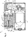
- the compressed air supply system 10, 10A, 10B, 10C is in the form of a device with a housing arrangement 50 which has a number of areas, with a motor M being located in a first area 51 and/or a motor M being located in a second area 52 the air compressor 21 that can be driven by the motor M and/or the air dryer 22 and the solenoid valve arrangement 40, 40A, 40B, 40C are arranged in a third area 53 connected to the second area 52 via a pressure source interface E1.
- 3 and 4 10 specifically show two constructively realized preferred embodiments of a compressed air supply system 10, 10' with a normally open solenoid valve arrangement 40.
- the compressed air supply systems 10, 10' are each realized as a device with a housing arrangement 50 which has a number of housing areas.
- a drive in the form of a motor M is arranged in a first area 51 and the air compressor 21 that can be driven by the motor M is arranged in a second area 52 .
- the air compressor 21 has a piston 55 which can be moved back and forth in the compression chamber 54 and which is driven by the motor M via a shaft and a connecting rod 56 .
- Air is supplied to the compression space 54 via an air supply interface E0 of the air supply 0 mentioned above. Compressed air at the outlet of the compression chamber 54 is transferred to a pressure source interface E1 for the above-mentioned compressed air supply 1 via an outlet valve 57 or the like.
- the compressed air is discharged into a third area 53 of the compressed air supply system 10, 10'.
- the third area 53 contains the air dryer 22 with drying container 58 and - in the compressed air supply system 10 'of 4 shown larger - normally open solenoid valve arrangement 40.
- the housing areas are associated with corresponding housing parts A, B, C, which are optionally sealed by one or more seals D against each other.
- the third area 53 has a housing part C and a cover T or in 4 Associated with cover T'.
- the air dryer 22 advantageously has a drying container 58 containing a desiccant through which compressed air can flow, which has a wall W forming a desiccant-free indentation G, with the solenoid valve arrangement 40, 40A, 40B, 40C being arranged at least partially, preferably completely, in the indentation G.
- the third housing part C is separated by a wall W of the drying container 58 filled with drying granulate and the cover T or in 4 lid T' formed.
- the dry granules are kept under pressure by a spring F in the drying container 58 .
- the wall W in turn forms on the bottom side of the drying container 58 an indentation G which is arranged symmetrically, ie in the present case parallel and centrally, to an axis of the drying container 58 and which is free of desiccant.
- the vent valve arrangement in the form of the normally open solenoid valve arrangement 40 is accommodated in the indentation G symmetrically to the axis of the drying container 58 .
- the cover T, T' tightly seals the indentation G together with the solenoid valve arrangement 40 located therein.
- a cover T , T ′ of the drying container 58 is advantageously arranged over the indentation (G) and has a ventilation area which is at least partially divided into pneumatic lines 72 by a seal 71 .
- the cover T, T' as part of the housing arrangement 50 of the compressed air supply system 10 not only accommodates seals 71 for sealing off the housing part C of the compressed air supply system 10, 10'.
- lines 72 protrude into the cover T, T' as part of a ventilation dome of the air dryer 22, which connect to corresponding passages in the drying container 58 and are guided in the cover T, T'.
- the seals 71 in the cover T, T' are designed as a molded seal.
- the cover T, T' is broken through by interfaces, with E2 forming a pressure source interface at the compressed air connection and E3 forming a ventilation interface at the ventilation connection 3 of the compressed air supply system 10 .
- the control interface S is used to connect to the above-mentioned control line 68 of the solenoid valve arrangement 40.
- the normally open solenoid valve arrangement 40 - both the arrangement of the pneumatic part 44 and the magnetic part 43 of the solenoid valve arrangement 40 - is designed in a common valve housing, i.e. modularly, and arranged in the indentation G of the wall W of the housing part C.
- a particularly compact arrangement of the normally open solenoid valve arrangement 40 in the drying container 58 i.e. specifically in the indentation G formed by this, can be achieved with this embodiment.
- a valve seat and a valve body of the pneumatic part are arranged in the indentation G.
- the U-shaped arrangement of the first, second and third areas 51, 52, 53 and the associated first, second and third housing parts A, B, C provides a space-saving compressed air supply system 10 which also has horizontal interfaces - namely S, E0, E1, E2, E3 - enabled.
- a weight saving is achieved in that the outer contour of the drying container 58 and the cover T, T′ of the air dryer 22 is used as part C of the housing arrangement 50 .
- FIG. 4 shows an enlarged view of an embodiment of the in 3 described air dryer 22 in a compressed air supply system 10 ', wherein the same reference numerals are expediently used for the same or similar parts or parts of the same or similar function.
- the arrows here show a venting flow P from the gallery 95 during venting, ie when the solenoid valve arrangement 40 is in the currentless open state.
- the magnetic part 43 is present by a bobbin 63 and a single armature 61 B formed, which by the coil body 63 when energized - to close the solenoid valve assembly 40 - can be activated.
- the armature 61B When the coil body 63 is de-energized, the armature 61B is clearly fixed by a valve spring 65 in such a way that a valve sealing element 61A mounted on the armature 61B is lifted from a valve seat 61C assigned to the valve sealing element 61A.
- the compressed air can flow as a venting flow P through a channel 66 forming the throttle 32 in a magnetic core 62 and past the armature 61 B - i.e. while flowing through the coil body 63 - through a venting dome in the cover T', namely the channels 72, to the venting interface E3 of the bleed port 3.
- the armature 61 B is arranged in a non-magnetic armature guide tube 64 .
- the solenoid valve arrangement 40 in the indentation G of the drying container 58 forms a channel through which air can flow through the drying container 58, which has an installation-free free space 67 upstream of the solenoid valve arrangement 40, the free space 67 and the solenoid valve arrangement 40 being arranged axially with respect to one another.
- the free space 67 is thus part of the ventilation line 30 described above.
- the cover T' is also provided with the reference to FIG 1 explained check valve 49 incorporated with residual pressure function.
- the incorporation of the non-return valve 49 together with a part of the ventilation dome in the cover T′ takes place in a flow-optimized manner, so that this is conducive to flexible and rapid ventilation of the compressed air supply system 10 or the pneumatic system 90 .
- the cover T' has a modular structure. For this purpose, it has a first cover plate T1 for representing a pneumatic functionality—namely the channels 72, the molded seal 71 and the interfaces E2, E3.
- the cover T′ also has a second cover plate T2 for representing an electrical and/or control-electrical functionality—namely the interface S and control electronics SE, which connect the interface S to the connection S′.
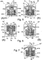
- FIG 5 shows in view (B) a with Fig. 6 (B) and Fig. 7 position of the solenoid valve arrangement 40' which is similar to the principle and normally open with a compressed air flow Q shown symbolically.
- Figure 5(B) illustrates a compressed air flow from the channel 66 to an opening 74 forming the throttle 32 on the magnetic core 62 and to two with the in 4 Visible lines 72 connected first openings 73.
- the armature 61 B is de-energized coil body 63 by the spring force of the valve spring 65 - pressed against a stop 75 - here compression spring.
- the normally closed solenoid valve arrangement 400 closes Coil body 630, the armature 610 is pulled into the coil body 630 against the spring force of the valve spring 650, so that the valve sealing element 610A is lifted from the valve seat 610C and the seat opening 760 is released. This allows the compressed air of the flow Q to flow from a channel 660 into the channel opening 740 forming a throttle, past the armature 610 through the seat opening 760 .
- Figure 6(A) shows in a modification to -with Figure 5(B) identical- Figure 6(B) a normally open solenoid valve arrangement 40", in which a pressure built up by the compressed air in turn of a flow Q in the direction of the venting flow P lies under the armature 61 in the energized closed state Fig. 6 (B) and Fig. 5 (B) shown normally open solenoid valve arrangement 40 'is a pressure of the compressed air in the energized closed state over the armature 61 B.
- Fig.6(A) shows an essentially mirrored arrangement of the components of the solenoid valve arrangement 40" in comparison to the solenoid valve arrangement 40' Figure 5(B) been described.
- the magnet valve arrangement 40, 40A, 40B, 40C advantageously has an armature 61B and/or valve seat 61C formed with elastomer and/or metal.
- 7 shows one to Fig. 5 (B) and Fig. 6 (B) structurally largely similar and practically identical in terms of functioning of a normally open solenoid valve arrangement 40''', in which, in contrast to Fig. 5 (B) and Fig. 6 (B) a valve seat 61C is designed as a metal stopper, which faces a metal valve seal 61A.
- the valve seal 61A and the valve seat 61C are arched and do not require an elastomeric valve sealing element, as is shown in FIG Fig. 6 (B) and Fig. 5 (B) is shown.
- Fig.8 and 9 show two preferred embodiments of a solenoid valve arrangement 40B, 40C, in which a relay valve 40.2B, 40.2C is arranged in the vent line 30 to hold a residual pressure.
- the relay valve 40.2B, 40.2C is designed to hold a residual pressure in the range of up to 1 bar, in particular a residual pressure of up to 3 bar.
- the compressed air supply system 10B, 10C provides that the pneumatic part 44B, 44C, which can be actuated directly via the magnetic part 43B, 43C, in a branch line, the compressed air supply line 20 - according to Fig.9 in a control branch line 47 or according to Fig.8 in a first branch line 47.1 - is open between a pressure-side valve connection X2 and a control-side valve connection Y2 of the branch line.
- the pneumatic part 44B, 44C in the form of a 3/2-way valve in the solenoid valve assembly 40B, 40C and opened in the branch line of the compressed air supply line 20 for pneumatic actuation of a relay valve 40.2B, 40.2C in the vent line 30.
- the relay valve 40.2B, 40.2C When the magnetic part 43B, 43C of the control valve 40.1 B, 40.1C is not actuated, the relay valve 40.2B, 40.2C is in a pilot-controlled state such that when pressure is applied, the relay valve 40.2B, 40.2C can move between a pressure-side valve connection X1' and a vent-side valve connection X1' Valve connection Z1' opens.
- the present compressed air supply system 10B provides a solenoid valve assembly 40B which is normally open in the form of what is known as a normally venting pilot operated assembly.
- the magnetic valve arrangement 40B consists of a normally open magnetic valve as a control valve 40.1B with a magnetic part 43B and a pneumatic part 44B.
- the relay valve 40.2B is part of the pneumatic part 44B.
- the total pressure of the air pressure volume in the compressed air supply line 20 is present at the control valve 40.1B, which - as a normally open version - passes this on to the relay valve 40.2B as a pilot pressure when the magnetic part 43B is not actuated.
- This arrangement can be implemented with comparatively small nominal diameters for the control valve 40.1 B and nevertheless comparatively large nominal diameters for the throttle 32 compared to the throttle 31 for the relay valve 40.2B in order to vent a compressed air volume from the compressed air supply line 20 to the vent 3 via the branch line 48.
- a sufficiently high pressure change amplitude for the regeneration of the air dryer 22 is ensured.
- the total pressure of the control valve 40.1B which is open without current, is present in the first branch line 47.1 designed as a vent line and thus also at the relay valve 40.2B.
- the compressed air supply line 20 and the second branch line 47.2 is secured with a first check valve 49.1.
- the entire air flow during venting is directed through the control valve 40.1 B via the throttle 31 and the second non-return valve 49.2, as well as through the air dryer 22 and the throttle 32 and the relay valve 40.2B, which is then opened with pilot control, into the vent line 30.
- the relay valve 40.2B switches through immediately as a result of the control pressure present at the further control-side valve connection Y1'; the control pressure is conveyed via an open pressure-side valve connection X2 and an open control-side valve connection Y2 of the normally open control valve 40.1 B in the first branch line 47.1 to the further control-side valve connection Y1′.
- the relay valve 40.2B opens the third branch line 48, which is designed as an additional vent line, to the vent line 30 to the vent 3.
- the second check valve 49.2 prevents the activation of the relay valve 40.2B via the second branch line 47.2 when conveying an air flow from the compressed air supply 1 to the compressed air connection 2 , when the control valve 40.1B is also closed, ie energized.
- the first check valve 49.1 also shuts off the gallery 95 to the air dryer 22 in order to prevent the air dryer 22 from being undesirably filled when the pressures in the pneumatic system 90 change.
- the control valve 40.1B is also closed, ie energized.
- FIG. 9 shows a pneumatic system 100C with a compressed air supply system 10C and a pneumatic system 90, here in the form of an air spring system.
- a pneumatic system 100C is equipped with a compressed air supply system 10C, in which the solenoid valve arrangement 40C—again normally open—but in the present case is designed as a fast-venting, indirectly pilot-controlled solenoid valve arrangement 40C.
- the normally open solenoid valve arrangement 40C has a partial pressure exposed control valve 40.1C for controlling a relay valve 40.2C for the indirect switching of a compressed air volume.
- the control valve 40.1C is in the form of a magnetic valve with a magnetic part 43C and a pneumatic part 44C, with the relay valve 40.2C being part of the pneumatic part 44C.
- the magnetic part 43C of the control valve 40.1C is in a non-actuated state and the pneumatic part 44C of the control valve 40.1C is open between a pressure-side valve connection X2 and a control-side valve connection Y2 in the control branch line 47 designed as a control line .
- the control pressure is present at the control-side valve connection Y1' of the relay valve 40.2C in the control branch line 47.
- relay valve 40.2C is in a piloted condition.
- only a minimum operating pressure is required to put the relay valve 40.2C in the open state, ie to open between the pressure-side valve connection X1′ and the ventilation-side valve connection Z1′ in the third branch line 48 designed as a ventilation line.
- the advantage of this quick-venting arrangement for the compressed air supply system 10C is that due to the comparatively small nominal diameter of the first throttle 31 in the compressed air supply line 20 compared to the larger nominal diameter of the second throttle 32 in the third branch line 48 designed as a vent line, only a small partial pressure of the total pressure a compressed air volume in the compressed air supply line 20 is required to control the relay valve 40.2C via the control valve 40.1C. Nevertheless will the main compressed air volume is vented via the third branch line 48 and the throttle 32 and the relay valve 40.2C to vent 3.
- An advantage of this quick-venting solenoid valve arrangement 40C in the compressed air supply system 10C is that the entire compressed air volume does not have to be routed through a single solenoid valve, but rather a small partial pressure of a partial compressed air volume supplied to the control valve 40.1C via the control branch line 47 designed as a control line is sufficient.
- This design which is similar in principle to a force-controlled or servo-controlled valve arrangement, enables the operating pressure to be increased to a comparably high pressure level and, at the same time, high compressed air volumes can be switched via the relay valve 40.2C.
- the relay valve 40.2C can be designed with a comparatively large nominal diameter.
- the ratio of the smaller nominal size of the first throttle 31 to the larger nominal size of the second throttle 32 is selected such that effective regeneration of the air dryer 22 is possible when the compressed air supply system 10C is vented.
- the compressed air supply system 10B and 10C with indirectly pilot-controlled venting solenoid valve arrangements have in common that a relay valve 40.2B or 40.2C of a solenoid valve arrangement 40B or 40C is in a "dry" line - i.e. "behind" the air dryer 22 in the venting direction - in each case is arranged in the third branch line 48 leading to the vent line 30 .
- a relay valve 40.2B or 40.2C being damaged due to external influences, for example freezing or the like.
- both indirectly pilot-controlled solenoid valve arrangements 40B, 40C require a minimum pilot control pressure in order to be able to release a necessary minimum cross-section, namely at least the cross-section of the throttle 32, with the relay piston of the relay valve 40.2B, 40.2C.
- a minimum pilot pressure is required to open the relay piston cleanly.
- the rapidly venting solenoid valve arrangement 40C this can be built up dynamically at least at the throttle 31 in the case of regeneration when the vehicle is lowered. If the air volume or pilot pressure is too low, a relay piston will not switch.
- the directly controlled solenoid valve arrangement 40A has advantages here, since only a comparatively low pilot pressure or no pilot pressure is required.
- a spring-loaded relay valve 40.2B or 40.2C can, on the one hand, assume a residual-pressure holding function if a suitable, optionally adjustable valve spring is provided.
- a relay pressure limiter 49' of the relay valve 40.2B, 40.2C is advantageously provided in a relay valve 40.2B, 40.2C, in which the pressure for the relay valve 40.2B, 40.2C can be limited by tapping the pressure in the branch line 48. In this way, even with a comparatively high operating pressure, a certain variability or tolerance with regard to pressure limitation can be achieved.
- a first throttle 31 in the compressed air supply system 10C can be selected to be larger than a first throttle 31 in the compressed air supply system 10B; the reason is that a main exhaust flow is not routed via the control valve 40.1C.
- compressed air can in principle be vented or discharged from a pneumatic system 100C more quickly than is the case with a pneumatic system 100B.
- good regeneration of the air dryer 22 is also achieved in the compressed air supply system 10C by adapting, preferably increasing, the nominal width of the second throttle 32.
- a pressure limiter is provided for all the previously explained solenoid valve arrangements 40A, 40B, 40C with a flow-adjustable pressure limitation.
- the pneumatic part 44A, 44B, 44C can have an opening pressure which can be set via the solenoid part 43A, 43B, 43C.
- a maximum pressure can be limited to a higher or lower value by setting a higher or lower current.
Landscapes
- Engineering & Computer Science (AREA)
- Mechanical Engineering (AREA)
- Transportation (AREA)
- Vehicle Body Suspensions (AREA)
- Fluid-Pressure Circuits (AREA)
- Magnetically Actuated Valves (AREA)
Description
Die Erfindung betrifft eine Druckluftversorgungsanlage gemäß dem Oberbegriff des Anspruchs 1. Weiter betrifft die Erfindung ein pneumatisches System gemäß dem Oberbegriff des Anspruchs 14 mit einer solchen Druckluftversorgungsanlage und ein Verfahren gemäß dem Oberbegriff des Anspruchs 15 zum Betreiben einer Pneumatikanlage.The invention relates to a compressed air supply system according to the preamble of
Eine Druckluftversorgungsanlage wird in Fahrzeugen aller Art, insbesondere zur Versorgung einer Luftfederanlage eines Fahrzeugs mit Druckluft, eingesetzt. Luftfederanlagen können auch Niveauregelungseinrichtungen umfassen, mit denen der Abstand zwischen Fahrzeugachse und Fahrzeugaufbau eingestellt werden kann. Eine Luftfederanlage eines eingangs genannten pneumatischen Systems umfasst eine Anzahl von an einer gemeinsamen Leitung (Galerie) pneumatisch angeschlossenen Luftbalgen, die mit zunehmender Befüllung den Fahrzeugaufbau anheben und entsprechend mit abnehmender Befüllung absenken können. Mit wachsendem Abstand zwischen Fahrzeugachse und Fahrzeugaufbau bzw. Bodenfreiheit werden die Federwege länger und auch größere Bodenunebenheiten können überwunden werden, ohne dass es zu einer Berührung mit dem Fahrzeugaufbau kommt. Solche Systeme werden in Geländefahrzeugen und Sport Utility Vehicles (SUV) eingesetzt. Insbesondere bei SUVs ist es bei sehr leistungsfähigen Motoren wünschenswert das Fahrzeug einerseits für hohe Geschwindigkeiten auf der Straße mit vergleichsweise geringer Bodenfreiheit zu versehen und andererseits für das Gelände mit einer vergleichsweise großen Bodenfreiheit zu versehen. Es ist weiter wünschenswert, eine Veränderung der Bodenfreiheit möglichst schnell umzusetzen, was die Anforderungen hinsichtlich Schnelligkeit, Flexibilität und Verlässlichkeit einer Druckluftversorgungsanlage erhöht.A compressed air supply system is used in vehicles of all kinds, in particular for supplying compressed air to an air spring system of a vehicle. Air spring systems can also include level control devices with which the distance between the vehicle axle and the vehicle body can be adjusted. An air spring system of a pneumatic system mentioned at the outset comprises a number of air bellows which are pneumatically connected to a common line (gallery) and which can raise the vehicle body as the filling increases and correspondingly lower it as the filling decreases. As the distance between the vehicle axle and the vehicle body or ground clearance increases, the spring deflections become longer and even larger bumps in the ground can be overcome without coming into contact with the vehicle body. Such systems are used in off-road vehicles and sport utility vehicles (SUV). With SUVs in particular, it is desirable with very powerful engines to provide the vehicle with comparatively low ground clearance for high speeds on the road on the one hand and with comparatively high ground clearance for off-road on the other hand. It is also desirable to change the ground clearance as quickly as possible, which increases the requirements for speed, flexibility and reliability of a compressed air supply system.
Eine Druckluftversorgungsanlage zur Verwendung in einem pneumatischen System mit einer Pneumatikanlage, beispielsweise einer zuvor beschriebenen Luftfederanlage, wird mit Druckluft aus einer Druckluftzuführung, beispielsweise im Rahmen eines Druckniveaus von 5 bis 20 bar, betrieben. Die Druckluft wird mit einem Luftverdichter (Kompressor) der Druckluftzuführung zur Verfügung gestellt. Die Druckluftzuführung ist zur Versorgung der Pneumatikanlage mit einem Druckluftanschluss pneumatisch verbunden und andererseits mit einem Entlüftungsanschluss pneumatisch verbunden. Über eine Entlüftungsventilanordnung kann durch Ablassen von Luft die Druckluftversorgungsanlage zum Entlüftungsanschluss hin entlüftet werden.A compressed air supply system for use in a pneumatic system with a pneumatic system, for example an air spring system described above, is operated with compressed air from a compressed air supply, for example at a pressure level of 5 to 20 bar. The compressed air is made available with an air compressor (compressor) of the compressed air supply. In order to supply the pneumatic system, the compressed air supply is pneumatically connected to a compressed air connection and, on the other hand, pneumatically connected to a ventilation connection. The compressed air supply system can be vented to the vent connection by releasing air via a vent valve arrangement.
Zur Sicherstellung eines langfristigen Betriebs der Druckluftversorgungsanlage weist diese einen Lufttrockner auf, mit dem die Druckluft zu trocknen ist. Dadurch wird die Ansammlung von Feuchtigkeit im Pneumatiksystem vermieden, was bei vergleichsweise niedrigen Temperaturen zu ventilschädigender Kristallbildung führen kann und ansonsten zu ungewünschten Defekten in der Druckluftversorgungsanlage und in der Pneumatikanlage führen kann. Ein Lufttrockner weist ein Trockenmittel auf, üblicherweise eine Granulatschüttung, welche von der Druckluft durchströmbar ist, so dass die Granulatschüttung - bei vergleichsweise hohem Druck - in der Druckluft enthaltene Feuchtigkeit durch Adsorption aufnehmen kann. Ein Lufttrockner kann gegebenenfalls als regenerativer Lufttrockner ausgelegt werden. Dies kann dadurch geschehen, dass die Granulatschüttung bei jedem Entlüftungszyklus - bei vergleichsweise niedrigem Druck - mit der getrockneten Druckluft aus dem Luftfederungssystem im Gegenstrom oder Gleichstrom relativ zur Befüllrichtung durchströmt werden. Dazu kann die Entlüfttungsventilanordnung geöffnet werden. Für eine solche - auch als Druckwechseladsorption bezeichnete - Anwendung hat es sich als wünschenswert erwiesen, eine Druckluftversorgungsanlage flexibel und gleichzeitig verlässlich auszulegen, insbesondere eine vergleichsweise schnelle Entlüftung mit einem dennoch für eine Regeneration des Lufttrockners ausreichendem Druckwechsel, zu ermöglichen.To ensure long-term operation of the compressed air supply system, it has an air dryer with which the compressed air is to be dried. This avoids the accumulation of moisture in the pneumatic system, which can lead to valve-damaging crystal formation at comparatively low temperatures and otherwise can lead to undesirable defects in the compressed air supply system and in the pneumatic system. An air dryer has a desiccant, usually a bed of granules through which the compressed air can flow, so that the bed of granules—at comparatively high pressure—can absorb moisture contained in the compressed air by adsorption. An air dryer can optionally be designed as a regenerative air dryer. This can be done in that the dried compressed air from the air suspension system flows through the bulk granulate during each venting cycle—at comparatively low pressure—in countercurrent or cocurrent relative to the direction of filling. To do this, the vent valve arrangement can be opened. For such an application—also referred to as pressure swing adsorption—it has proven desirable to design a compressed air supply system flexibly and at the same time reliably, in particular to enable comparatively rapid venting with a pressure swing that is nevertheless sufficient for regeneration of the air dryer.
Aus
Eine eingangs genannte Druckluftversorgungsanlage ist auch in
Aus
Aus
Alle vorgenannten Lösungen sehen bei der Entlüftungsventilanordnung in Form einer steuerbaren Magnetventilanordnung vor, dass bei einem nicht angesteuerten Zustand des Magnetteils der Pneumatikteil der Magnetventilanordnung geschlossen ist; d.h. die Lösungen sehen eine stromlos geschlossene Magnetventilanordnung vor. Insbesondere hinsichtlich der in
Aus der
Die
Die
Die
Aufgabe der Erfindung ist es, eine Vorrichtung und ein Verfahren anzugeben, welche im Hinblick auf den Stand der Technik verbessert ist. Insbesondere soll eine alternative Lösung zum Stand der Technik angegeben werden, welche die mit einem stromlos geschlossenen Magnetventil verbundenen Nachteile beseitigt. Insbesondere soll eine Entlüftungs- und/oder Trockenleistung der Druckluftversorgungsanlage verbessert sein.The object of the invention is to specify a device and a method which is improved with regard to the prior art. In particular, an alternative solution to the prior art is to be specified, which eliminates the disadvantages associated with a normally closed solenoid valve. In particular, a ventilation and/or drying performance of the compressed air supply system should be improved.
Die Aufgabe hinsichtlich der Vorrichtung wird gelöst durch eine Druckluftversorgungsanlage der eingangs genannten Art, bei der erfindungsgemäß die Merkmale des kennzeichnenden Teils des Anspruchs 1 vorgesehen ist. Die Aufgabe hinsichtlich des Verfahrens wird gelöst durch ein erfindungsgemäßes Verfahren des Anspruchs 15.The object with regard to the device is achieved by a compressed air supply system of the type mentioned in the introduction, in which the features of the characterizing part of
Die Erfindung geht von der Überlegung aus, dass bei einem stromlos geschlossenen Magnetventil im Rahmen einer als Magnetventilanordnung ausgebildeten Entlüftungsventilanordnung - insbesondere im Falle eines ungewollt am Ventilsitz haftenden Ankers oder dgl. Ventilkörpers - die Gefahr besteht, dass bei anhaltender Luftförderung des Luftverdichters ungewollt ein Überdruck in der Druckluftversorgungsanlage entsteht. Dieser kann im ungünstigsten Fall auch auf eine Pneumatikanlage eines pneumatischen Systems übergreifen und zu Schäden in der Pneumatikanlage führen. Dies wäre insbesondere im Falle einer Luftfederanlage höchst unvorteilhaft. Vorteilhaft ist ein Druckbegrenzer mit der Magnetventilanordnung, z. B. an einem Magnetventil zur direkten Schaltung eines Gesamtdruckluftvolumens oder an einem Relaisventil, realisiert. Im Rahmen der Erfindung ist ein Strom einstellbarer Druckbegrenzer bei der stromlos offenen Magnetventilanordnung vorgesehen mit wesentlichen Vorteilen gegenüber dem bisherigen Einsatz von stromlos geschlossenen Magnetventilanordnungen. Die Erfindung hat erkannt, dass der Schaltaufwand zum Betreiben eines stromlos offenen Magnetventils vergleichsweise gering ist. Das Konzept der Erfindung schlägt ausgehend von diesen Überlegungen vor, eine Magnetventilanordnung zu verwenden, bei der in nicht angesteuertem Zustand des Magnetteils, insbesondere bei stromlosem Magnetteil, der Pneumatikteil geöffnet ist. Eine solche Anordnung wird im Folgenden auch als stromlos offene Magnetventilanordnung bezeichnet. Insbesondere ist vorgesehen, dass der unmittelbar über den Magnetteil der Magnetventilanordnung aktuierbare Pneumatikteil der Magnetventilanordnung in einer Entlüftungsleitung oder anderen Zweigleitung der Druckluftversorgungsleitung zwischen einem druckseitigen Ventilanschluss (X) und einem entlüftungsseitigen und/oder steuerseitigen Ventilanschluss (Y, Z) geöffnet ist.The invention is based on the consideration that with a normally closed solenoid valve in the context of a vent valve arrangement designed as a solenoid valve arrangement - especially in the case of an armature or similar valve body unintentionally sticking to the valve seat - there is a risk that if the air supply of the air compressor unintentionally creates overpressure in the compressed air supply system. In the worst case, this can also spread to a pneumatic system of a pneumatic system and lead to damage in the pneumatic system. This would be extremely disadvantageous, particularly in the case of an air spring system. A pressure limiter with the solenoid valve arrangement, e.g. B. realized on a solenoid valve for direct switching of a total compressed air volume or on a relay valve. Within the scope of the invention, a current-adjustable pressure limiter is provided in the normally open solenoid valve arrangement, with significant advantages over the previous use of normally closed solenoid valve arrangements. The invention has recognized that the switching effort for operating a normally open solenoid valve is comparatively low. Based on these considerations, the concept of the invention proposes using a magnetic valve arrangement in which the pneumatic part is open when the magnetic part is not activated, in particular when the magnetic part is de-energized. Such an arrangement is also referred to below as a normally open solenoid valve arrangement. In particular, it is provided that the pneumatic part of the solenoid valve arrangement that can be actuated directly via the solenoid part of the solenoid valve arrangement is open in a vent line or other branch line of the compressed air supply line between a pressure-side valve connection (X) and a vent-side and/or control-side valve connection (Y, Z).
Das Konzept der Erfindung umfasst - in einer ersten Variante - in vorteilhafter Weise eine Magnetventilanordnung zur direkten Schaltung eines Druckluftvolumens. Vorzugsweise weist eine solche Magnetventilanordnung nur ein einziges oder mehrere Entlüftungsventile auf. Im Falle eines einzigen Entlüftungsventils kann ein Druckluftvolumen durch das einzige Entlüftungsventil direkt geschalten werden. Im Falle mehrerer Entlüftungsventile können diese beispielsweise als ein primäres Entlüftungsventil und sekundäres Entlüftungsventil realisiert sein. Das primäre Entlüftungsventil und das sekundäre Entlüftungsventil können je nach Bedarf gleichzeitig nacheinander oder einzeln zur Entlüftung eines Druckluftvolumens geschaltet werden. Eine solche direkt gesteuerte Entlüftungs-Magnetventilanordnung ist insbesondere frei von einem Steuerventil. Sie kann ein einziges oder mehrere ein Druckluftvolumen schaltende Magnetventile aufweisen, von denen wenigstens eines oder eine Teilanzahl oder alle gemäß dem Konzept der Erfindung stromlos offen sind. Es eignen sich insbesondere stromlos offene Einzelanker- oder Doppelanker-Magnetventile.The concept of the invention comprises—in a first variant—advantageously a solenoid valve arrangement for direct switching of a compressed air volume. Such a solenoid valve arrangement preferably has only a single vent valve or a plurality of vent valves. In the case of a single vent valve, a compressed air volume can be switched directly through the single vent valve. In the case of several vent valves, these can be implemented, for example, as a primary vent valve and a secondary vent valve. The primary bleed valve and the secondary bleed valve can be switched simultaneously, one after the other, or individually to bleed a volume of compressed air, as required. Such a directly controlled venting solenoid valve arrangement is in particular free of a control valve. It can have a single solenoid valve or several solenoid valves that switch a compressed air volume, of which at least one or a number or all of them are normally open according to the concept of the invention. Normally open single armature or double armature solenoid valves are particularly suitable.
Das Konzept der Erfindung ist nicht beschränkt auf eine direkt gesteuerte Magnetventilanordnung.The concept of the invention is not limited to a directly controlled solenoid valve arrangement.
Das Konzept der Erfindung umfasst mit Vorteil versehen - in einer zweiten Variante - eine indirekt gesteuerte normal entlüftende Anordnung zur indirekten Schaltung eines Druckluftvolumens, bei der ein einem Gesamtdruck ausgesetztes Steuerventil zur Steuerung eines Relaisventils vorgesehen ist. Bei einer solchen normal entlüftenden Anordnung ist in einem nicht angesteuerten Zustand des Magnetteils des Steuerventils der Pneumatikteil des Steuerventils geöffnet, so dass das Relaisventil in einem vorgesteuerten Zustand ist. Im Falle einer Druckbeaufschlagung öffnet das Relaisventil sofort; das Relaisventil erweist sich im Ergebnis als praktisch stromlos offen. In
Das Konzept umfasst - in einer dritten Variante - eine Magnetventilanordnung in Form einer indirekt gesteuerten Magnetventilanordnung. Dies kann eine schnell entlüftende Anordnung zur indirekten Schaltung eines Druckluftvolumens sein, bei der ein einem Teildruck ausgesetztes Steuerventil zur Steuerung eines Relaisventils vorgesehen ist. Bei nicht angesteuertem Zustand des Magnetteils des Steuerventils ist der Pneumatikteil des Steuerventils bei einer indirekt gesteuerten schnelllüftenden Anordnung geöffnet, so dass das Relaisventil in einem vorgesteuerten Zustand ist. Im Falle einer Druckbeaufschlagung öffnet das Relaisventil sofort; das Relaisventil erweist sich im Ergebnis praktisch als stromlos offen. In
Eine indirekt gesteuerte Ventilanordnung - schnell oder normal entlüftend - kann ähnlich einer servogesteuerten Ventilanordnung oder zwangsgesteuerten Ventilanordnung verstanden werden. Eine direkt gesteuerte Ventilanordnung weist dagegen ein oder mehrere direkt gesteuerte Ventile auf, die einfacher realisierbar sind.An indirectly controlled valving - quick or normal venting - can be understood to be similar to a servo controlled valving or positively controlled valving. A directly controlled valve arrangement, on the other hand, has one or more directly controlled valves that are easier to implement.
Grundsätzlich vermeidet das Konzept der Erfindung einer stromlos geöffneten Magnetventilanordnung den Nachteil eines so genannten Ventilklebers, d. h. den Nachteil eines am Ventilsitz haftenden Ventilkörpers, da der Ventilkörper bei einem stromlos offenen Magnetventil nicht die längste Zeit am Ventilsitz angeordnet ist. Außerdem ist, bei ständiger Durchflutung eines stromlos offenen Magnetventils, eine Selbstreinigung des Ventilsitzes gegeben. Dies trifft insbesondere auf eine direkt gesteuerte Magnetventilanordnung zu. Die Druckluftversorgungsanlage ist vorteilhaft gegen den externen Eintrag von Verschmutzungen geschützt.Basically, the concept of the invention of a normally open solenoid valve arrangement avoids the disadvantage of a so-called valve stick, i. H. the disadvantage of a valve body sticking to the valve seat, since the valve body is not arranged on the valve seat for the longest time in a normally open solenoid valve. In addition, a self-cleaning of the valve seat is given with constant flooding of a normally open solenoid valve. This applies in particular to a directly controlled solenoid valve arrangement. The compressed air supply system is advantageously protected against external contamination.
Es hat sich gezeigt, dass jedenfalls separate Sicherheitsventile beim Konzept der Erfindung weitgehend überflüssig sein können. Selbst im Falle einer ungewollt anhaltenden Förderung des Luftverdichters (z. B. aufgrund eines Relaisklebers am Motor des Verdichters) geht diese Förderung aufgrund der stromlos offenen Magnetventilanordnung der Entlüftungsventilanordnung ins Freie. Somit kann ein Zustand ungewollter Luftförderung nicht zu einer Überdruckbelastung der Druckluftversorgungsanlage oder gar der Pneumatikanlage führen. Selbst wenn ein Fehlerfall auftreten sollte fördert vorteilhaft ein dann nicht mehr steuerbarer Luftverdichter nicht gegen einen voreingestellten Maximaldruck. Vielmehr fördert dieser dann nur - bei indirekt gesteuerten Anordnungen nahezu und bei direkt gesteuerten Anordnungen gänzlich - gegen Atmosphärendruck. Zudem ergibt sich bei allen zuvor genannten Varianten der Vorteil, dass bei einem Anlaufen des Luftverdichters ein druckloser Anlauf aufgrund der stromlos offenen Magnetventilanordnung möglich ist.It has been shown that in any case separate safety valves can be largely superfluous in the concept of the invention. Even in the event of an unintentionally sustained delivery of the air compressor (e.g. due to a relay adhesive on the motor of the compressor), this delivery is released due to the normally open solenoid valve arrangement of the vent valve arrangement. In this way, a state of undesired air delivery cannot lead to an overpressure load on the compressed air supply system or even on the pneumatic system. Even if an error should occur, an air compressor that can then no longer be controlled advantageously does not pump against a preset maximum pressure. Rather, this promotes then only - with indirectly controlled arrangements almost and with directly controlled arrangements completely - against atmospheric pressure. In addition, all of the variants mentioned above have the advantage that when the air compressor starts up, it can start up without pressure because the solenoid valve arrangement is open when it is not energized.
Bei allen drei vorgenannten Varianten einer Magnetventilanordnung - d. h. sowohl bei einer direkt gesteuerten Entlüftungsmagnetventilanordnung als auch bei einer schnell entlüftenden oder normal entlüftenden indirekt vorgesteuerten Magnetventilanordnung - ergibt sich der Vorteil, dass diese bei einem jeden Umfüllen von Druckluft in der Pneumatikanlage, d.h. zum Beispiel von einem Speicher zu einem Balgventil, angesteuert geschlossen werden können, d.h. der Magnetteil wird angesteuert und der Pneumatikteil wird geschlossen. Somit entsteht praktisch kein Druckverlust über einen Lufttrockner. Insbesondere kann sich dadurch, wenn zweckmäßig, ein Abtrennen der Pneumatikanlage von der Druckluftversorgungsanlage erübrigen.In all three aforementioned variants of a solenoid valve assembly - i. H. with a directly controlled venting solenoid valve arrangement as well as with a quickly venting or normally venting indirectly pilot-controlled solenoid valve arrangement - there is the advantage that these can be closed in a controlled manner each time compressed air is transferred in the pneumatic system, i.e. from an accumulator to a bellows valve, for example , i.e. the magnetic part is activated and the pneumatic part is closed. This means that there is practically no pressure loss across an air dryer. In particular, if this is expedient, a disconnection of the pneumatic system from the compressed air supply system can be dispensed with.
Zu einem Pneumatikteil einer Magnetventilanordnung gehören insbesondere die pneumatisch wirkenden Teile, wie das Ventil als solches mit Ventilkörper, Ventilsitz, Ventildichtung, Ventilgehäuse oder dergleichen. Zu einem Magnetteil einer Magnetventilanordnung gehören insbesondere die elektrisch und/oder magnetisch wirkenden Teile, wie Aktuier- und Steuermittel für das Ventil mit Spule, Anker, Spulenkörper, Steuerleitung oder dergleichen.A pneumatic part of a solenoid valve arrangement includes in particular the pneumatically acting parts, such as the valve as such with valve body, valve seat, valve seal, valve housing or the like. A magnet part of a magnet valve arrangement includes in particular the electrically and/or magnetically acting parts, such as actuating and control means for the valve with a coil, armature, coil body, control line or the like.
Die Erfindung führt auf ein pneumatisches System mit einer erfindungsgemäßen Druckluftversorgungsanlage.The invention leads to a pneumatic system with a compressed air supply system according to the invention.
Weitere vorteilhafte Weiterbildungen der Erfindung sind den Unteransprüchen zu entnehmen und geben im Einzelnen vorteilhafte Möglichkeiten an, das oben erläuterte Konzept im Rahmen der Aufgabenstellung sowie hinsichtlich weiterer Vorteile zu realisieren.Further advantageous developments of the invention can be found in the dependent claims and specify advantageous possibilities in detail for realizing the concept explained above within the scope of the task and with regard to further advantages.
Im Rahmen der oben genannten ersten bevorzugten weiterbildenden Variante ist die stromlos offene Magnetventilanordnung zur direkten Schaltung eines Gesamtdruckluftvolumens ausgelegt, also vorzugsweise in Form einer stromlos offenen direkt gesteuerten Entlüftungsmagnetventilanordnung frei von einem Steuerventil ausgeführt. In Weiterbildung des Konzepts der Erfindung kann der Pneumatikteil der Magnetventilanordnung in der Entlüftungsleitung zwischen einem druckseitigen Ventilanschluss (X) und einem entlüftungsseitigen Ventilanschluss (Z) geöffnet sein. Für eine Regeneration des Lufttrockners vorteilhaft, ist eine erste Drossel in einer Druckluftversorgungsleitung oder einer daran direkt angeschlossenen Zweigleitung, - z. B. einer Steuerzweigleitung oder dergleichen - angeordnet. Vorteilhaft ist in einer Entlüftungsleitung oder einer daran direkt angeschlossenen Zweigleitung - z. B. einer Entlüftungszweigleitung oder dergleichen - eine zweite Drossel angeordnet. Die Nennweite der ersten Drossel liegt vorzugsweise unterhalb der Nennweite der zweiten Drossel. Dies führt vorteilhaft dazu, dass ein größter Druckabfall am Lufttrockner erfolgt. Dies wiederum hat eine vergleichsweise hohe Druckwechselamplitude am Lufttrockner zur Folge, was für die Regeneration des Lufttrockners im Rahmen einer Druckwechseladsorption besonders vorteilhaft ist. Bevorzugt ist in der Entlüftungsleitung ein Ventil zum Halten eines Restdrucks angeordnet ist. Im Rahmen einer bevorzugten Weiterbildung der ersten Variante ist in einer Entlüftungsleitung ein Rückschlagventil und/oder ein Relaisventil angeordnet. Bevorzugt wird eine Restdruckfunktion über einen vorgesteuerten Relaiskolben des Relaisventils erreicht. Die Restdruckfunktion ist vorzugsweise ausgelegt, einen Restdruck insbesondere von 1 bis 3 bar- vorzugsweise im Bereich von oberhalb 1 bar, insbesondere wenigstens 1,5 bar- im System, d.h. in der Druckluftversorgungsanlage und/oder der Pneumatikanlage zu halten. Insbesondere im Hinblick auf Luftfederanlagen hat sich ein solcher Restdruck als vorteilhaft erwiesen, um in den Bälgen einer Luftfederanlage einen ausreichenden Restdruck zu halten. Dies vermeidet ein ungewolltes Zusammenklappen oder Einklemmen der Bälge.As part of the first preferred variant mentioned above, the normally open solenoid valve arrangement is designed for direct switching of a total compressed air volume, i.e. preferably in the form of a normally open, directly controlled ventilation solenoid valve arrangement without a control valve. In a further development of the concept of the invention, the pneumatic part of the solenoid valve arrangement can be open in the ventilation line between a pressure-side valve connection (X) and a ventilation-side valve connection (Z). A first throttle in a compressed air supply line or a branch line directly connected to it, e.g. B. a control branch line or the like - arranged. It is advantageous in a vent line or a branch line directly connected to it - e.g. B. a ventilation branch line or the like - arranged a second throttle. The nominal width of the first throttle is preferably below the nominal width of the second throttle. This advantageously leads to the greatest pressure drop occurring at the air dryer. This in turn results in a comparatively high pressure swing amplitude at the air dryer, which is particularly advantageous for the regeneration of the air dryer as part of a pressure swing adsorption. A valve for maintaining a residual pressure is preferably arranged in the ventilation line. As part of a preferred development of the first variant, a check valve and/or a relay valve is arranged in a vent line. A residual pressure function is preferably achieved via a pilot-operated relay piston of the relay valve. The residual pressure function is preferably designed to maintain a residual pressure of in particular 1 to 3 bar, preferably in the range above 1 bar, in particular at least 1.5 bar, in the system, i.e. in the compressed air supply system and/or the pneumatic system. In particular with regard to air spring systems, such a residual pressure has proven to be advantageous in order to keep a sufficient residual pressure in the bellows of an air spring system. This prevents the bellows from collapsing or getting caught.
Im Rahmen der oben genannten besonders bevorzugten weiterbildenden zweiten Variante ist vorgesehen, die Magnetventilanordnung zur indirekten Schaltung eines Gesamtdruckluftvolumens mit einem Steuerventil zur Steuerung eines Relaisventils zu versehen, das einem Gesamtdruck ausgesetzt ist, d. h. die Magnetventilanordnung ist in Form einer normal entlüftenden indirekt vorgesteuerten Anordnung gebildet. Vorteilhaft bildet das vorgesteuerte Relaisventil eine Restdruckfunktion aus. Vorteilhaft erübrigt sich dadurch ein separates Rückschlagventil. Ein Druckbegrenzer beim Relaisventil lässt sich vorteilhaft über eine Ventilfeder realisieren. Grundsätzlich kann bei allen weiterbildenden Varianten der Erfindung ein Druckbegrenzer vorgesehen sein, insbesondere auch an einem Ventil einer Magnetventilanordnung zur direkten Schaltung eines Druckluftvolumens.As part of the above-mentioned particularly preferred further developing second variant, it is provided that the solenoid valve arrangement for indirect switching of a total volume of compressed air is provided with a control valve for controlling a relay valve which is exposed to a total pressure, i. H. the solenoid valve assembly is in the form of a normally venting indirect pilot assembly. The pilot operated relay valve advantageously forms a residual pressure function. A separate non-return valve is advantageously unnecessary as a result. A pressure limiter in the relay valve can advantageously be implemented using a valve spring. In principle, a pressure limiter can be provided in all further developing variants of the invention, in particular also on a valve of a solenoid valve arrangement for the direct switching of a compressed air volume.
Im Rahmen der oben genannten dritten besonders bevorzugten weiterbildenden Variante der Erfindung ist die Magnetventilanordnung zur indirekten Schaltung eines Gesamtdruckluftvolumens vorgesehen und weist ein einem Teildruck ausgesetztes Steuerventil zur Steuerung eines Relaisventils auf, d. h. die Anordnung ist als eine indirekt vorgesteuerte schnell entlüftende Magnetventilanordnung gebildet. Auch bei dieser Anordnung übernimmt das vorgesteuerte Relaisventil eine Restdruckfunktion. Ein separates Rückschlagventil ist vorteilhaft nicht notwendig. Ein Druckbegrenzer kann beim Relaisventil über eine Ventilfeder realisiert werden.In the context of the above-mentioned third particularly preferred further development variant of the invention, the solenoid valve arrangement is provided for indirect switching of a total volume of compressed air and has a partial pressure-exposed control valve for controlling a relay valve, i. H. the assembly is formed as an indirect pilot operated quick exhaust solenoid valve assembly. In this arrangement, too, the pilot operated relay valve assumes a residual pressure function. A separate check valve is advantageously not necessary. A pressure limiter can be implemented with the relay valve using a valve spring.
In Weiterbildung des Konzepts der Erfindung bei der zweiten und dritten Variante kann der Pneumatikteil der Magnetventilanordnung in einer Zweigleitung der Druckluftversorgungsleitung zwischen einem druckseitigen Ventilanschluss (X) und einem steuerseitigen Ventilanschluss (Y) zur pneumatischen Ansteuerung eines Relaisventils in der Entlüftungsleitung über die Zweigleitung geöffnet sein.In a further development of the concept of the invention in the second and third variant, the pneumatic part of the solenoid valve arrangement can be opened in a branch line of the compressed air supply line between a pressure-side valve connection (X) and a control-side valve connection (Y) for the pneumatic activation of a relay valve in the ventilation line via the branch line.
Darüber hinaus hat es sich bei allen vorgenannten weiterbildenden Varianten als besonders vorteilhaft erwiesen, dass die Magnetventilanordnung eine stromeinstellbare Druckbegrenzung aufweist. Es hat sich gezeigt, dass sich ein Druckbegrenzer, soweit dieser durch eine Federbelastung eines Ventils mittels einer Ventilfeder realisiert ist, nur in gewissen Grenzen einstellen lässt. Andererseits kann es für eine ausreichend flexible Versorgung der Pneumatikanlage, insbesondere Luftfederanlage, mit einer Druckluftversorgungsanlage vorteilhaft sein, einen Druckbegrenzer zur Verfügung zu stellen, der über einen vergleichsweise großen Druckbereich einstellbar ist. Die Erfindung sieht dazu vor, dass die Magnetventilanordnung einen stromeinstellbaren Druckbegrenzer aufweist. Drücke zum zuverlässigen Auffüllen eines Speichers in einer Luftfederanlage können gegebenenfalls sehr unterschiedlich von Drücken zum Auffüllen eines Balgs einer Luftfederanlage sein. Ein stufenlos stromeinstellbarer Druckbegrenzer ermöglicht eine variable und flexibel einstellbare Druckbegrenzung in einem Bereich durchaus zwischen 10 und 30 bar. Außerdem kann in einem solchen Bereich ein ausreichend breites Toleranzfeld von Druckbegrenzungen berücksichtigt werden. Besonders vorteilhaft lässt sich diese Weiterbildung dadurch realisieren, dass der Pneumatikteil der Magnetventilanordnung einen über den Magnetteil stromeinstellbaren Öffnungsdruck aufweist. Je nach Betriebssituation kann bei einer stromlos offenen Magnetventilanordnung ein Maximaldruck der Magnetventilanordnung durch einen geringeren Strom vergleichsweise gering eingestellt und einen höheren Strom vergleichsweise hoch eingestellt werden. Dadurch kann zum einen ein Balg einer Luftfederanlage vor Überladung geschützt sein, beispielsweise vor Überladung oberhalb eines Drucks von 11 bis 13 bar. Auch kann ein Speicher einer Luftfederanlage vor Überladung geschützt sein, beispielsweise oberhalb eines Drucks von 20 bis 25 bar. Ein stromeinstellbarer Druckbegrenzer erweist sich insbesondere dann als vorteilhaft, wenn dieser ein mechanisch wirkendes Druckbegrenzungsventil ersetzen kann.In addition, it has proven to be particularly advantageous in all of the aforementioned further developing variants that the solenoid valve arrangement has a flow-adjustable pressure limiter. It has been shown that a Pressure limiter, as far as this is realized by a spring loading of a valve by means of a valve spring, can only be adjusted within certain limits. On the other hand, for a sufficiently flexible supply of the pneumatic system, in particular the air spring system, with a compressed air supply system, it can be advantageous to provide a pressure limiter that can be adjusted over a comparatively large pressure range. To this end, the invention provides that the solenoid valve arrangement has a flow-adjustable pressure limiter. Pressures for reliably filling a reservoir in an air spring system can possibly be very different from pressures for filling a bellows of an air spring system. A steplessly adjustable pressure limiter enables variable and flexibly adjustable pressure limitation in a range between 10 and 30 bar. In addition, a sufficiently wide tolerance range of pressure limitations can be taken into account in such a range. This development can be implemented particularly advantageously in that the pneumatic part of the magnet valve arrangement has an opening pressure that can be adjusted in terms of current via the magnet part. Depending on the operating situation, a maximum pressure of the magnet valve arrangement can be set comparatively low by a lower current and a higher current can be set comparatively high in a normally open solenoid valve arrangement. As a result, on the one hand, a bellows of an air spring system can be protected against overloading, for example against overloading above a pressure of 11 to 13 bar. An accumulator of an air spring system can also be protected against overcharging, for example above a pressure of 20 to 25 bar. A flow-adjustable pressure limiter proves to be particularly advantageous when it can replace a mechanically acting pressure-limiting valve.
Im Rahmen einer besonders bevorzugten Weiterbildung ist die Druckluftversorgungsanlage in Form einer Einrichtung mit einer Gehäuseanordnung gebildet, die eine Anzahl von Gehäusebereichen aufweist. Dadurch kann die Druckluftversorgungsanlage je nach Bedarf in eine vorteilhafte Anzahl von Bereichen segmentiert bzw. modular aufgebaut werden. Vorzugsweise ist in einem ersten Bereich ein Antrieb angeordnet. Vorteilhaft ist in einem zweiten Bereich der vom Antrieb antreibbare Luftverdichter angeordnet. Vorteilhaft ist in einem mit dem zweiten Bereich über eine Druckquellen-Schnittstelle verbundenen dritten Bereich der Lufttrockner und die Magnetventilanordnung enthalten. Diese Aufteilung hat sich insbesondere durch Anordnung des ersten bis dritten Bereichs in einer U-förmigen Anordnung bewährt. Dadurch können in Einbaulage der Anlage Schnittstellen, wie eine Druckquellen-Schnittstelle oder eine Druckluftversorgungs-Schnittstelle oder eine Entlüftungs-Schnittstelle, bevorzugt horizontal, grundsätzlich je nach Kundenerfordernis angeordnet werden. Grundsätzlich kann diese Aufteilung auch durch Anordnung des ersten bis dritten Bereichs in einer anderen als U-förmigen Anordnung, z. B. einer Z-förmigen Anordnung realisiert werden.As part of a particularly preferred development, the compressed air supply system is in the form of a device with a housing arrangement that has a number of housing areas. As a result, the compressed air supply system can be segmented into an advantageous number of areas or set up modularly, depending on requirements. A drive is preferably arranged in a first area. The air compressor, which can be driven by the drive, is advantageously arranged in a second area. The air dryer and the solenoid valve arrangement are advantageously contained in a third area connected to the second area via a pressure source interface. This division has proven its worth in particular by arranging the first to third areas in a U-shaped arrangement. As a result, in the installation position of the system, interfaces such as a pressure source interface or a compressed air supply interface or a venting interface can be arranged, preferably horizontally, in principle depending on customer requirements. In principle, this division can also be achieved by arranging the first to third areas in an arrangement other than a U-shape, e.g. B. a Z-shaped arrangement can be realized.
Vorzugsweise weist der Lufttrockner einen ein Trockenmittel enthaltenden von Druckluft durchströmbaren Trockenbehälter auf, der eine Trockenmittel freie Einbuchtung bildende Wandung aufweist. Ein solcher Trockenbehälter hat sich als besonders geeignet erwiesen, die Magnetventilanordnung wenigstens teilweise, vorzugsweise vollständig, in der Einbuchtung aufzunehmen. Dadurch kann die Magnetventilanordnung einerseits durch den Trockenbehälter vor Außeneinflüssen geschützt werden und andererseits kann die in der Magnetventilanordnung sich entwickelnde Wärme vorteilhaft zur Trocknerregeneration genutzt sein.The air dryer preferably has a drying container containing a desiccant through which compressed air can flow and which has a wall forming an indentation free of desiccant. Such a drying container has proven to be particularly suitable for accommodating the magnetic valve arrangement at least partially, preferably completely, in the indentation. As a result, on the one hand, the magnet valve arrangement can be protected from external influences by the drying container and, on the other hand, the heat developing in the magnet valve arrangement can be advantageously used for dryer regeneration.
Vorzugsweise ist ein Deckel des Trockenbehälters über der Einbuchtung angeordnet. Ein solcher Deckel hat vorzugsweise einen wenigstens teilweise durch eine Dichtung, insbesondere eine Formdichtung, in pneumatische Leitungen unterteilten Entlüftungsbereich. Dadurch kann vorteilhaft ein Entlüftungsdom des Lufttrockners wenigstens teilweise im Bereich der Gehäuseanordnung angeordnet werden. Insbesondere ist ein Entlüftungsdom des Lufttrockners wenigstens teilweise im Bereich eines Deckels angeordnet, wobei der Deckel über der Einbuchtung des Trockenbehälters vorgesehen ist. Vorteilhaft bildet zudem bauraumsparend der Trockenbehälter und/oder der Deckel einen Teil der Gehäuseanordnung. Der Deckel kann besonders vorteilhaft mit einer integrierten Dichtung und/oder einem Rückschlagventil zum dichten Verschließen der Einbuchtung und der darin enthaltenen Magnetventilanordnung vorgesehen sein. Der Deckel kann neben einer pneumatischen Funktionalität - wie der eines Entlüftungsdoms mit pneumatischen Leitungen, Ventilen und Anschlüssen - auch eine elektrische bzw. steuerelektrische Funktionalität aufweisen. Der Deckel kann insbesondere ausgebildet sein, pneumatische Schnittstellen - wie die Druckluftversorgungs-Schnittstelle und die Entlüftungs-Schnittstelle oder ein Ventil in Form eines Rückschlagventils - zur Verfügung zu stellen. Der Deckel kann insbesondere eine elektrische Schnittstelle - wie eine Steuer-Schnittstelle - zur Verfügung zu stellen.A lid of the drying container is preferably arranged over the indentation. Such a cover preferably has a ventilation area that is at least partially divided into pneumatic lines by a seal, in particular a molded seal. As a result, a ventilation dome of the air dryer can advantageously be arranged at least partially in the area of the housing arrangement. In particular, a ventilation dome of the air dryer is arranged at least partially in the area of a cover, the cover being provided over the indentation of the drying container. In addition, the drying container and/or the cover advantageously forms part of the housing arrangement in a space-saving manner. The cover can particularly advantageously be provided with an integrated seal and/or a non-return valve for tightly closing the indentation and the magnetic valve arrangement contained therein. In addition to a pneumatic functionality—such as that of a ventilation dome with pneumatic lines, valves and connections—the cover can also have an electrical or control-electrical functionality. In particular, the cover can be designed to provide pneumatic interfaces—such as the compressed air supply interface and the venting interface or a valve in the form of a check valve. In particular, the cover can provide an electrical interface—such as a control interface.
Im Rahmen einer besonders bevorzugten Weiterbildung ist vorgesehen, dass die Magnetventilanordnung einen mit Elastomer und/oder Metall gebildeten Anker und/oder Ventilsitz aufweist. Vorzugsweise weist ein Magnetventil der Magnetventilanordnung einen Ventilkörper bzw. eine Ventildichtung und/oder einen Ventilsitz auf, die auf einem Elastomer anschlagen. Grundsätzlich kann ein Ventilkörper und/oder ein Ventilsitz auch auf einem Metall anschlagen - ein Elastomer hat sich darüber hinaus als besonders vorteilhaft zum Dichten eines Magnetventils erwiesen. Andererseits kann ein Elastomer dazu neigen, sich im Betriebsfalle - je nach Anteil von Weichmachern - zu setzen und in ungünstigen Fällen kann ein Elastomer dazu führen, dass ein Ventilkörper bzw. eine Ventildichtung am Ventilsitz klebt oder anfriert. Dies kann dazu führen, dass der Anker des Magnetventils blockiert (sog. Ventilkleber). Die Kombination des vorliegenden Konzepts einer stromlos offenen Magnetventilanordnung und ein gemäß der Weiterbildung vorgesehenes Elastomer am Ventilkörper oder Anker bzw. Ventildichtung und/oder Ventilsitz beseitigt diese Nachteile. Da bei einer stromlos offenen Magnetventilanordnung das Elastomer nur im Betriebsfalle das Ventil abdichtet ist ein oben genannter Ventilkleber sicher vermieden.In the context of a particularly preferred development, it is provided that the magnet valve arrangement has an armature and/or valve seat formed with elastomer and/or metal. A magnetic valve of the magnetic valve arrangement preferably has a valve body or a valve seal and/or a valve seat which strike an elastomer. In principle, a valve body and/or a valve seat can also strike a metal—an elastomer has also proven to be particularly advantageous for sealing a solenoid valve. On the other hand, an elastomer can tend to settle during operation - depending on the proportion of plasticizers - and in unfavorable cases an elastomer can cause a valve body or a valve seal to stick or freeze to the valve seat. This can lead to the armature of the solenoid valve becoming blocked (so-called valve sticking). The combination of the present concept of a normally open solenoid valve arrangement and an elastomer provided according to the development on the valve body or armature or valve seal and/or valve seat eliminates these disadvantages. Since the elastomer seals the valve in a normally open solenoid valve arrangement only during operation, an above-mentioned valve adhesive is used safely avoided.
Ausführungsbeispiele der Erfindung werden nun nachfolgend anhand der Zeichnung beschrieben. Diese soll die Ausführungsbeispiele nicht notwendigerweise maßstäblich darstellen, vielmehr ist die Zeichnung, wo zur Erläuterung dienlich, in schematisierter und/oder leicht verzerrter Form ausgeführt. Im Hinblick auf Ergänzungen der aus der Zeichnung unmittelbar erkennbaren Lehren wird auf den einschlägigen Stand der Technik verwiesen. Dabei ist zu berücksichtigen, dass vielfältige Modifikationen und Änderungen betreffend die Form und das Detail einer Ausführungsform vorgenommen werden können, ohne von der allgemeinen Idee der Erfindung abzuweichen.Exemplary embodiments of the invention will now be described below with reference to the drawing. This is not necessarily intended to represent the exemplary embodiments to scale, rather the drawing, where useful for explanation, is in schematic and/or slightly distorted form. With regard to additions to the teachings that can be seen directly from the drawing, reference is made to the relevant state of the art. In this context, it must be taken into account that a wide variety of modifications and changes relating to the form and detail of an embodiment can be made without deviating from the general idea of the invention.
Der Einfachheit halber sind dort wo sinnvoll, nachfolgend für identische oder ähnliche Teile oder Teile mit identischer oder ähnlicher Funktion gleiche Bezugszeichen verwendet.For the sake of simplicity, where appropriate, the same reference symbols are used below for identical or similar parts or parts with an identical or similar function.
Weitere Vorteile, Merkmale und Einzelheiten der Erfindung ergeben sich aus der nachfolgenden Beschreibung der bevorzugten Ausführungsbeispiele sowie anhand der Zeichnung; diese zeigt in:
-
Fig. 1 ein Schaltungsdiagramm eines ersten pneumatischenSystems 100A mit einer Luftfederanlage und einer ersten Druckluftversorgungsanlage, nämlich mit einer Magnetventilanordnung in Form einer direkt gesteuerten Entlüftungs-Magnetventilanordnung gemäß einer ersten weiterbildenden Variante der Erfindung; -
Fig. 2 ein schematischer Vergleich von Bestromungszuständen (Ansteuerungen Ein/Aus) einer stromlos geschlossenen Magnetventilanordnung (A) einerseits und einer stromlos offenen Magnetventilanordnung (B) gemäß einer der beschriebenen Ausführungsformen andererseits - dies für die Betriebszustände (I) Fördern, (II) Entlüften/Absenken, (III) Heben aus Speicher; -
Fig. 3 eine bevorzugte konstruktive Realisierung einer Druckluftversorgungsanlage mit einer bevorzugten stromlos offenen Magnetventilanordnung zur Verwendung bei der ersten Druckluftversorgungsanlage derFig. 1 - dies mit symbolischer Darstellung einer Entlüftungsströmung P und einer BelüftungsströmungP ; -
Fig. 4 eine vergrößerte Ansicht der Magnetventilanordnung derFig. 3 in stromlos offenem Zustand mit symbolischer Entlüftungsströmung P; -
Fig. 5 in Ansicht (B) eine vergrößerte Detaildarstellung einer ersten abgewandelten stromlos offenen Magnetventilanordnung in stromlos offenem Zustand zur Verwendung bei einer Druckluftversorgungsanlage derFig. 1 - dies im Unterschied zu einer üblichen stromlos geschlossenen Magnetventilanordnung in Ansicht (A); -
Fig. 6 in Ansicht (A) und (B) zwei weitere Abwandlungen einer stromlos offenen Magnetventilanordnung zur Verwendung bei einer Druckluftversorgungsanlage derFig. 1 , wobei in der Abwandlung (A) eine Druckseite unter dem Anker liegt und in der Abwandlung (B) - wie beiFig. 5 (B) - eine Druckseite über dem Anker liegt; -
Fig. 7 eine weitere Abwandlung einer Magnetventilanordnung, bei welcher der Ventilsitz als metallischer Anschlag gebildet ist und die darüber hinaus wie inFig. 5 (B) oder Fig. 6 (B) realisiert ist; -
Fig. 8 ein Schaltungsdiagramm eines zweiten pneumatischenSystems 100B mit einer Luftfederanlage und einer zweiten Druckluftversorgungsanlage, nämlich mit einer Magnetventilanordnung in Form einer normal entlüftenden indirekt vorgesteuerten Magnetventilanordnung gemäß einer zweiten weiterbildenden Variante der Erfindung; -
Fig. 9 ein Schaltungsdiagramm eines dritten pneumatischenSystems 100C mit einer Luftfederanlage und einer dritten Druckluftversorgungsanlage, nämlich mit einer Magnetventilanordnung in Form einer schnell entlüftenden indirekt vorgesteuerten Magnetventilanordnung gemäß einer dritten weiterbildenden Variante der Erfindung.
-
1 a circuit diagram of a firstpneumatic system 100A with an air spring system and a first compressed air supply system, namely with a solenoid valve arrangement in the form of a directly controlled venting solenoid valve arrangement according to a first variant of the invention; -
2 a schematic comparison of energization states (controls on/off) of a normally closed solenoid valve arrangement (A) on the one hand and a normally open solenoid valve arrangement (B) according to one of the described embodiments on the other hand - this for the operating states (I) conveying, (II) venting/lowering, (III) lifting from storage; -
3 a preferred constructive realization of a compressed air supply system with a preferred normally open solenoid valve arrangement for use in the first compressed air supply system1 - this with a symbolic representation of a ventilation flow P and a ventilation flowP ; -
4 an enlarged view of the solenoid valve assembly of FIG3 in the normally open state with symbolic venting flow P; -
figure 5 in view (B) is an enlarged detail view of a first modified normally open solenoid valve arrangement in the normally open state for use in a compressed air supply system1 - This in contrast to a conventional normally closed solenoid valve arrangement in view (A); -
6 in view (A) and (B) two further modifications of a normally open solenoid valve arrangement for use in a compressed air supply system of1 , wherein in the modification (A) a pressure side is under the armature and in the modification (B) - as inFigure 5(B) - one pressure side is above the anchor; -
7 a further modification of a solenoid valve arrangement, in which the valve seat is formed as a metallic stop and which, moreover, as inFig. 5 (B) or Fig. 6 (B) is realized; -
8 a circuit diagram of a secondpneumatic system 100B with an air spring system and a second compressed air supply system, namely with a solenoid valve arrangement in the form of a normally venting, indirectly pilot-controlled solenoid valve arrangement according to a second further developing variant of the invention; -
9 a circuit diagram of a thirdpneumatic system 100C with an air spring system and a third compressed air supply system, namely with a solenoid valve arrangement in the form of a rapidly venting, indirectly pilot-controlled solenoid valve arrangement according to a third variant of the invention.
Die Druckluftversorgungsanlage 10A dient zum Betreiben der Pneumatikanlage 90 in Form der Luftfederanlage und versorgt die Galerie 95 derselben über einen Druckluftanschluss 2. Die Druckluftversorgungsanlage 10A weist außerdem einen Entlüftungsanschluss 3 und eine Luftzuführung 0 mit einer Ansaugung auf. In Befüllrichtung stromabwärts des Druckluftanschlusses 2 ist die Luftfederanlage mit den steuerbaren Magnetventilen 93, 94 angeordnet. Dem Entlüftungsanschluss 3 in Entlüftungsrichtung stromabwärts nachgeschaltet bzw. der Luftzuführung 0 stromaufwärts vorgeschaltet ist jeweils ein Filter 3.1 bzw. 0.1.The compressed
In einer pneumatischen Verbindung zwischen Luftzuführung 0 und Druckluftzuführung 1 weist die Druckluftversorgungsanlage 10A darüber hinaus einen Luftverdichter 21 in Form eines Kompressors auf, der über einen Motor M angetrieben zur Versorgung der Druckluftzuführung 1 mit Druckluft vorgesehen ist. In einer pneumatischen Verbindung zwischen Druckluftzuführung 1 und Druckluftanschluss 2 ist weiter ein Lufttrockner 22 und eine erste Drossel 31, hier als Regenerationsdrossel, angeordnet. Der Filter 0.1, die Luftzuführung 0, der Luftverdichter 21, die Druckluftzuführung 1, der Lufttrockner 22 und die erste Drossel 31 sind zusammen mit dem Druckluftanschluss 2 in einer zur Galerie 95 führenden Druckluftversorgungsleitung 20 in dieser Reihenfolge angeordnet.In a pneumatic connection between the
In einer pneumatischen Verbindung zwischen Druckluftzuführung 1 und Entlüftungsanschluss 3 der Druckluftversorgungsanlage 10A ist eine Entlüftungsventilanordnung in Form einer steuerbaren - dem Konzept der Erfindung folgend - stromlos offenen Magnetventilanordnung 40A mit einem Magnetteil 43A und einem Pneumatikteil 44A für einen Entlüftungsanschluss 3 zum Ablassen von Luft vorgesehen. Die Magnetventilanordnung 40A ist in einer die pneumatische Verbindung bildenden Entlüftungsleitung 30 mit einer zweiten, hier als Entlüftungsdrossel, dienenden Drossel 32 und dem Entlüftungsanschluss 3 angeordnet. Anders ausgedrückt ist bei der stromlos offenen Magnetventilanordnung 40A in nicht angesteuertem Zustand des Magnetteils 43A, der Pneumatikteil 44A geöffnet. Konkret ist vorliegend die Magnetventilanordnung 40A zur direkten Schaltung eines Druckluftvolumens ausgelegt. Der unmittelbar über den Magnetteil 43 aktuierbare Pneumatikteil 44A in der Entlüftungsleitung 30 der Druckluftversorgungsleitung 20 ist zwischen einem druckseitigen Ventilanschluss X1 und einem entlüftungsseitigen Ventilanschluss Z1 geöffnet.In a pneumatic connection between the
Mit Vorteil versehen ist ein druckluftanschlussseitiger eine pneumatische Kammer bildender Leitungsabschnitt der Entlüftungsleitung 30 an der Druckluftzuführung 1 zur pneumatischen Anbindung der Magnetventilanordnung 40A an die Druckluftversorgungsleitung 20 angeschlossen. Dies hat zur Folge, dass im Falle einer Entlüftung der Druckluftversorgungsanlage 10A über die Entlüftungsleitung 30 Druckluft entlüftet wird, welche vor dem Lufttrockner 22 entnommen wird, also vereinfacht gesagt ungetrocknete Luft.Advantageously, a line section of the
Aus
Im Einzelnen ergibt sich die Funktionsweise der Druckluftversorgungsanlage 10A, anhand von
Beim Erreichen des Speicherenddrucks in der Pneumatikanlage 90, vorliegend in einem Druckbereich von etwa 15 bis 20 bar im Speicher und 5 bis 10 bar in den Bälgen, wird die Druckluftversorgungsanlage 10A entlüftet. Für die Magnetventilanordnung 40A ist für die zweite Drossel 32 ein größeres Nennweitenmaß vorgesehen als für die erste Drossel 31, damit ein für die Regeneration des Lufttrockners möglichst große Druckwechselamplitude entstehen kann. Dies erlaubt eine vorteilhafte Entlüftung der Druckluftversorgungsanlage 10A und/oder Regeneration des Lufttrockners 22.When the storage end pressure in the
So wird zum Befüllen eines Speichers 92 zunächst die Entlüftungsleitung 30 durch Bestromung der Magnetventilanordnung 40A mit einem Steuerstrom geschlossen, um einen Druckaufbau im Speicher 92 zu ermöglichen. Vorliegend kann ein Entlüften der Druckluftversorgungsanlage 10A nach Erreichen des Speicherenddrucks, d.h. beim Erreichen des so genannten Speicherfüllen-Endes, durch Abschalten des Steuerstromes für einen Magnetteil 43A der stromlos offenen Magnetventilanordnung 40A erfolgen. Ein Entlüften im Falle einer Fahrzeugabsenkung im Regelbetrieb kann durch die bereits geöffnete - da stromlos offene - Magnetventilanordnung 40A problemlos erfolgen. Dabei ist durch einen geeigneten Druckabfall über den Lufttrockner 22 eine Regeneration des Lufttrockners 22 als auch ein flexibles und schnelles Entlüften durch Auslegung der Nennweite der Drosseln 31, 32 zweckmäßig gewährleistet.Thus, in order to fill an
Mit Vorteil versehen weist die Druckluftversorgungsanlage 10A darüber hinaus ein Rückschlagventil 49 auf, welches vorliegend eine Restdruckhaltefunktion hat. Zum einen dient das Rückschlagventil 49 zur Verhinderung eines Fremdkörpereintrags in die Druckluftversorgungsanlage 10A zusätzlich zum Filter 3.1. Darüber hinaus dient die Restdruckhaltefunktion des Rückschlagventils 49 zur Aufrechterhaltung eines Mindestdrucks in der Druckluftversorgungsanlage 10A. Aufgrund der über der Drossel 31 zur Galerie 95 offenen Druckluftversorgungsleitung 20 liegt der Restdruck auch für die Pneumatikanlage 90 in Form der Luftfilteranlage vor. Dieser Restdruck - vorliegend in Höhe von 1,5 bar - verhindert ein Zusammenkleben der Bälge 91 für den Fall, dass ein Entlüften der Druckluftversorgungsanlage 10A zusammen mit der Pneumatikanlage 90 erfolgt. Konkret wird dadurch verhindert, dass die Balgwände der Bälge 91 eingeklemmt oder beschädigt werden.Advantageously, the compressed
Außerdem ist bei einem Pneumatikteil 44A der Magnetventilanordnung 40A vorteilhaft ein stromeinstellbaren Druckbegrenzer 69 des Pneumatikteils 44A vorgesehen sein, bei welchem sich unter Abgreifen des Druckes in der Entlüftungsleitung 30 der Druck für die Magnetventilanordnung 40A beschränken lässt. Auf diese Weise kann selbst bei einem vergleichsweise hohen Betriebsdruck eine gewisse Variabilität bzw. Toleranz hinsichtlich einer Druckbegrenzung erreicht werden. Vorliegend wird dies dadurch realisiert, dass der Schaltpunkt des Pneumatikteils 44A abhängig von der Stromstärke eines Steuerstroms im Magnetteil 43A variabel einstellbar ist. Je nach Fahrzeugsituation, Temperatur des Systems oder sonstiger druckrelevanter Systembelange kann der Schaltpunkt des Pneumatikteils 44A stromstärke-variabel eingestellt werden. Durch den stromgesteuerten Druckbegrenzer 69 ist sichergestellt, dass der Galeriedruck den statischen Öffnungsdruck eines als Magnetventil 93 ausgebildeten Niveauregelventils und einen Innendruck eines Balgs 91 nicht übersteigt. Zusätzlich kann auch eine Druckmessung in der Galerie 95 oder im Speicher 92 erfolgen.In addition, a
Üblicherweise kann ein Balgdruck die Magnetventile 93 nicht aufdrücken und unterstützt eine Ventilfeder, indem vorliegend ein Balgdruck über einem Ventilanker anliegt. Bei Druckschwankungen im Balg 91, wie er bei Schlechtwegstrecken oder sonstigen dynamischen, Einflüssen auftreten kann, wird so vermieden, dass die Magnetventile 93 aufgedrückt werden. Praktisch nur im Falle einer ungewollt anhaltenden Förderung des Luftverdichters kann ein Galeriedruck so hoch werden, dass ein Balgventil aufgedrückt und das Fahrzeug ungewollt angehoben wird. Das könnte zu instabilen Fahrzuständen führen. Ein Druckbegrenzer vermeidet sicher einen solchen Fall bei Anlagen mit geschlossenen Entlüftungsschaltungen. Bei einer vorliegend beschriebenen stromlos offenen Schaltung wird eine solche Gefahr jedoch per se vermieden, da ein Luftverdichter zumeist ins Freie fördern würde.Usually, a bellows pressure cannot open the
Aus der Ansicht (B) der
In Ansicht (A) ist zum Vergleich die Bestromung einer üblicherweise stromlos geschlossenen Magnetventilanordnung gezeigt. Es zeigt sich, dass für den Betriebszustand (I) eine solche stromlos geschlossene Magnetventilanordnung normalerweise zweimal geöffnet werden muss (Nr. 1 und Nr. 2), nämlich wenigstens im Falle einer Entlüftung vor dem Fördern, falls ein Restdruck zu entlüften ist, einerseits und einer Entlüftung nach dem Fördern beim Befüllungsende andererseits, soweit nicht überschüssiges Druckpotenzial anderweitig, z.B. durch einen Druckaustausch zwischen Komponenten eines pneumatischen Systems erfolgen kann. Ebenso muss eine stromlos geschlossene Magnetventilanordnung für einen Betriebszustand (II) durch dauerhafte Bestromung geöffnet werden (Nr. 3), um eine Entlüftung bzw. ein Absenken der Fahrzeugkarosserie zu ermöglichen. Schließlich muss in einem Betriebszustand (III) nach dem Heben einer Fahrzeugkarosserie mit Druckluft aus einem Speicher 92 eine stromlos geschlossene Magnetventilanordnung einmal zum Entlüften der Druckluftversorgungsanlage bestromt, d.h. geöffnet werden (Nr. 4).View (A) shows the energization of a normally normally closed solenoid valve arrangement for comparison. It turns out that for the operating state (I) such a normally closed solenoid valve arrangement has to be opened twice (No. 1 and No. 2), namely at least in the case of venting before delivery, if a residual pressure has to be vented, on the one hand and venting after delivery at the end of filling, on the other hand, unless excess pressure potential can otherwise occur, e.g. through a pressure exchange between components of a pneumatic system. Likewise, a normally closed solenoid valve arrangement for an operating state (II) must be opened by permanent energization (No. 3) in order to allow venting or lowering of the vehicle body. Finally, in an operating state (III) after a vehicle body has been lifted with compressed air from a
Im Ergebnis zeigt sich, dass die Taktrate einer Betätigung bzw. Ansteuerung, d. h. Bestromung bzw. Schalthäufigkeit der stromlos offenen Magnetventilanordnung 40A im Unterschied zu einer stromlos geschlossenen Magnetventilanordnung geringer ist, wenn alle Betriebszustände (I), (II) und (III) zusammen betrachtet werden. Es hat sich gezeigt, dass dies insbesondere für schnell und flexibel zu betätigende Druckluftversorgungsanlagen, beispielsweise zur Verwendung in einem Geländefahrzeug oder einem SUV relevant wird. Für häufig wechselnde Betriebszustände (I), (II), und (III) hat sich eine Druckluftversorgungsanlage 10A mit einer stromlos offenen Magnetventilanordnung 40A als besonders vorteilhaft erwiesen. Darüber hinaus ist ein langanhaltender Kontakt von Ventilkörper und Ventilsitz bei der stromlos offenen Magnetventilanordnung 40A vorteilhaft zur Vermeidung von Ventilklebern unterbunden.The result shows that the cycle rate of an actuation or control, ie energization or switching frequency of the normally open
Im Rahmen einer besonders bevorzugten Ausführungsform ist die Druckluftversorgungsanlage 10, 10A, 10B, 10C in Form einer Einrichtung mit einer Gehäuseanordnung 50 gebildet, die eine Anzahl von Bereichen aufweist, wobei in einem ersten Bereich 51 ein Motor M und/oder in einem zweiten Bereich 52 der vom Motor M antreibbare Luftverdichter 21 und/oder in einem mit dem zweiten Bereich 52 über eine Druckquellen-Schnittstelle E1 verbundenen dritten Bereich 53 der Lufttrockner 22 und die Magnetventilanordnung 40, 40A, 40B, 40C angeordnet ist.
Vorteilhaft weist der Lufttrockner 22 einen ein Trockenmittel enthaltenden von Druckluft durchströmbaren Trockenbehälter 58 auf, der eine eine trockenmittelfreie Einbuchtung G bildende Wandung W aufweist, wobei die Magnetventilanordnung 40,40A, 40B, 40C wenigstens teilweise, vorzugsweise vollständig, in der Einbuchtung G angeordnet ist.The
Das dritte Gehäuseteil C ist vorliegend durch eine Wandung W des mit Trockengranulat gefüllten Trockenbehälters 58 und dem Deckel T bzw. in
Ein Deckel T , T' des Trockenbehälters 58 ist vorteilhaft über der Einbuchtung (G) angeordnet und weist einen wenigstens teilweise durch eine Dichtung 71 in pneumatische Leitungen 72 unterteilten Entlüftungsbereich auf. Vorliegend nimmt der Deckel T, T' als Teil der Gehäuseanordnung 50 der Druckluftversorgungsanlage 10 nicht nur Dichtungen 71 zum dichten Abschließen des Gehäuseteils C der Druckluftversorgungsanlage 10, 10' auf. Darüber hinaus ragen in den Deckel T, T' als Teil eines Entlüftungsdoms des Lufttrockners 22 Leitungen 72, welche an entsprechende Durchführungen im Trockenbehälter 58 anschließen und im Deckel T, T' geführt sind. Zur Bildung der Leitungen 72 sind die Dichtungen 71 im Deckel T, T' als Formdichtung ausgeführt. Außerdem wird der Deckel T, T' durch Schnittstellen durchbrochen, wobei E2 eine Druckquellen-Schnittstelle bei dem Druckluftanschluss bildet und E3 eine Entlüftungs-Schnittstelle beim Entlüftungsanschluss 3 der Druckluftversorgungsanlage 10 bildet. Die Steuer-Schnittstelle S dient zur Anbindung an die oben genannte Steuerleitung 68 der Magnetventilanordnung 40.A cover T , T ′ of the drying
Vorliegend ist die stromlos offene Magnetventilanordnung 40 - sowohl die Anordnung des Pneumatikteils 44 als auch des Magnetteils 43 der Magnetventilanordnung 40 - in einem gemeinsamen Ventilgehäuse, also modular, ausgeführt und in der Einbuchtung G der Wandung W des Gehäuseteils C angeordnet. Unter Weiterbildung des Konzepts der Erfindung lässt sich mit dieser Ausführungsform eine besonders kompakte Anordnung der stromlos offenen Magnetventilanordnung 40 im Trockenbehälter 58 d.h. konkret in der durch diesen gebildeten Einbuchtung G erreichen. Insbesondere ist dabei ein Ventilsitz und ein Ventilkörper des Pneumatikteils in der Einbuchtung G angeordnet. Dadurch ist die Magnetventilanordnung 40 besonders gut geschützt gegen äußere Einflüsse im Trockenbehälter 58 untergebracht.In the present case, the normally open solenoid valve arrangement 40 - both the arrangement of the
Insgesamt ist durch die U-förmige Anordnung des ersten, zweiten und dritten Bereichs 51, 52, 53 und der zugeordneten ersten, zweiten und dritten Gehäuseteile A, B, C eine bauraumsparende Druckluftversorgungsanlage 10 zur Verfügung gestellt, welche zudem horizontale Schnittstellen - nämlich S, E0, E1, E2, E3 - ermöglicht. Zudem wird eine Gewichtseinsparnis dadurch erreicht wird, dass die Außenkontur des Trockenbehälters 58 und des Deckels T, T' des Lufttrockners 22 als Teil C der Gehäuseanordnung 50 genutzt wird.Overall, the U-shaped arrangement of the first, second and
In den Deckel T' ist vorliegend auch das hier nicht näher bezeichnete anhand von
Grundsätzlich weist die Magnetventilanordnung 40, 40A, 40B, 40C vorteilhaft einen mit Elastomer und/oder Metall gebildeten Anker 61 B und/oder Ventilsitz 61 C auf.
Konkret zeigt
Konzeptionell besteht zwischen der Druckluftversorgungsanlage 10B und 10C mit als indirekt vorgesteuerte Entlüftungsmagnetventilanordnungen die Gemeinsamkeit, dass ein Relaisventil 40.2B bzw. 40.2C einer Magnetventilanordnung 40B bzw. 40C in einer "trockenen" Leitung -also in Entlüftungsrichtung "hinter" dem Lufttrockner 22- nämlich jeweils in der zur Entlüftungsleitung 30 führenden dritten Zweigleitung 48 angeordnet ist. Damit besteht vorteilhaft eine vergleichsweise geringe Gefahr, dass ein Relaisventil 40.2B oder 40.2C aufgrund äußerer Einflüsse beschädigt wird, beispielsweise einfriert oder dergleichen. Des Weiteren benötigen beide indirekt vorgesteuerten Magnetventilanordnungen 40B, 40C einen Mindestvorsteuerdruck, um mit dem Relaiskolben des Relaisventils 40.2B, 40.2C einen notwendigen Mindestquerschnitt, nämlich mindestens den Querschnitt der Drossel 32 freigeben zu können. Zum sauberen Öffnen des Relaiskolbens wird ein Mindestvorsteuerdruck benötigt. Dieser kann im Falle der schnell entlüftenden Magnetventilanordnung 40C jedenfalls an der Drossel 31 im Falle der Regeneration beim Ablassen des Fahrzeugs dynamisch aufgebaut werden. Bei zu geringen Luftmengen bzw. Vorsteuerdrücken schaltet ein Relaiskolben nicht. Hier hat die direkt gesteuerte Magnetventilanordnung 40A Vorteile, da nur ein vergleichsweise geringer bzw. kein Vorsteuerdruck erforderlich ist.Conceptually, the compressed
In beiden Fällen der indirekt vorgesteuerten Magnetventilanordnungen 40B, 40C entfällt jedenfalls grundsätzlich die Notwendigkeit eines separaten Rückschlagventils 49 der
Als Unterschied der Fälle der indirekt vorgesteuerten Magnetventilanordnungen 40B, 40C ist festzustellen, dass jedenfalls grundsätzlich eine erste Drossel 31 bei der Druckluftversorgungsanlage 10C größer gewählt werden kann als eine erste Drossel 31 bei der Druckluftversorgungsanlage 10B; der Grund liegt darin, dass ein Hauptentlüftungsstrom nicht über das Steuerventil 40.1C geführt wird. Dadurch kann grundsätzlich ein schnelleres Entlüften bzw. Ablassen von Druckluft aus einem pneumatischen System 100C erfolgen als dies bei einem pneumatischen System 100B der Fall ist. Gleichwohl wird auch bei der Druckluftversorgungsanlage 10C eine gute Regeneration des Lufttrockners 22 unter Anpassung, vorzugsweise Erhöhung, der Nennweite der zweiten Drossel 32 erreicht.The difference between the cases of indirectly pilot-controlled
In besonders vorteilhafter Weise ist ein Druckbegrenzer für alle zuvor erläuterten Magnetventilanordnungen 40A, 40B, 40C mit eine stromeinstellbaren Druckbegrenzung vorgesehen. Dazu kann bei einer stromlos offenen Magnetventilanordnung 40A, 40B, 40C der Pneumatikteil 44A, 44B, 44C einen über den Magnetteil 43A, 43B, 43C einstellbaren Öffnungsdruck aufweisen. Je nach Bedarf kann durch Einstellen eines höheren oder geringeren Stroms ein maximaler Druck auf einen höheren oder geringeren Wert begrenzt werden.In a particularly advantageous manner, a pressure limiter is provided for all the previously explained
- 00
- Luftzuführungair supply
- 0.10.1
- Filterfilter
- 11
- Druckluftzuführungcompressed air supply
- 22
- Druckluftanschlusscompressed air connection
- 33
- Entlüftungsanschlussvent port
- 3.13.1
- Filterfilter
- 10, 10' 10A, 10B, 10C10, 10' 10A, 10B, 10C
- Druckluftversorgungsanlagecompressed air supply system
- 2020
- Druckluftversorgungsleitungcompressed air supply line
- 2121
- Luftverdichterair compressor
- 2222
- Lufttrocknerair dryer
- 3030
- Entlüftungsleitungvent line
- 3131
- erste Drosselfirst throttle
- 3232
- zweite Drosselsecond throttle
- 40, 40', 40", 40"', 40A, 40B, 40C40, 40', 40", 40"', 40A, 40B, 40C
- Magnetventilanordnungsolenoid valve assembly
- 401.B, 40.1C401.B, 40.1C
- Steuerventilcontrol valve
- 40.2B, 40.2C40.2B, 40.2C
- Relaisventilrelay valve
- 43, 43A, 43B, 43C43, 43A, 43B, 43C
- Magnetteilmagnetic part
- 44, 44A, 44B, 44C44, 44A, 44B, 44C
- Pneumatikteilpneumatic part
- 4747
- Steuerzweigleitungcontrol branch line
- 47.1,47.1,
- erste Zweigleitung als Entlüftungsleitungfirst branch line as vent line
- 47.247.2
- zweite Zweigleitung als weitere Entlüftungsleitungsecond branch line as another vent line
- 4848
- dritte Zweigleitung als noch weitere Entlüftungsleitungthird branch line as yet another vent line
- 4949
- Rückschlagventilcheck valve
- 49'49'
- Relais-Druckbegrenzer des Relaisventils 40.2B, 40.2CRelay valve 40.2B, 40.2C relay pressure limiter
- 49.149.1
- erstes Rückschlagventilfirst check valve
- 49.249.2
- zweites Rückschlagventilsecond check valve
- 5050
- Gehäuseanordnunghousing arrangement
- 5151
- erster Bereichfirst area
- 5252
- zweiter Bereichsecond area
- 5353
- dritter Bereichthird area
- 5454
- Verdichtungsraumcompression space
- 5555
- KolbenPistons
- 5656
- Pleuelconnecting rod
- 5757
- Auslassventiloutlet valve
- 5858
- Trockenbehälterdrying container
- 61 B61 b
- Ankeranchor
- 61A61A
- Ventil-Dichtelementvalve sealing element
- 61C61C
- Ventilsitzvalve seat
- 6262
- Magnetkernmagnetic core
- 6363
- Spulenkörperbobbin
- 6464
- Ankerführungsrohranchor guide tube
- 6565
- Ventilfedervalve spring
- 6666
- Kanalchannel
- 6767
- Freiraumfree space
- 6868
- Steuerleitungcontrol line
- 6969
-
stromgesteuerter Druckbegrenzer des Pneumatikventils 44Acurrent-controlled pressure limiter of the
pneumatic valve 44A - 7171
- Dichtungpoetry
- 7272
- LeitungManagement
- 7373
- erste Öffnungfirst opening
- 7474
- Drossel bildende ÖffnungThrottle forming opening
- 7575
- Anschlagattack
- 7676
- zweite Öffnungsecond opening
- 9090
- Pneumatikanlagepneumatic system
- 9191
- Balgbellows
- 9292
- SpeicherStorage
- 9393
- Magnetventil, Niveauregelventil für BalgSolenoid valve, level control valve for bellows
- 9494
- Magnetventil, Niveauregelventil für SpeicherSolenoid valve, level control valve for accumulator
- 9595
- Galeriegallery
- 9696
- Ventilblockvalve block
- 100, 100A, 100B, 100C100, 100A, 100B, 100C
- pneumatisches Systempneumatic system
- 400400
- Magnetventilmagnetic valve
- 610610
- Ankeranchor
- 610A610A
- Ventildichtelementvalve sealing element
- 610C610C
- Ventilsitzvalve seat
- 630630
- Spulenkörperbobbin
- 650650
- Ventilfedervalve spring
- 660660
- Kanalchannel
- 760760
- Sitzöffnungseat opening
- 740740
- Kanalöffnungchannel opening
- AA
- erstes Gehäuseteilfirst housing part
- BB
- zweites Gehäuseteilsecond housing part
- CC
- drittes Gehäuseteilthird case part
- DD
- Dichtungpoetry
- E0E0
- Luftzuführungs-Schnittstelle, SchnittstelleAir supply interface, interface
- E1E1
- Druckquellen-Schnittstelle, SchnittstellePressure source interface, interface
- E2E2
- Druckluftversorgungs-Schnittstelle, SchnittstelleCompressed air supply interface, interface
- E3E3
- Entlüftungs-Schnittstelle, SchnittstelleVent interface, interface
- Ff
- FederFeather
- GG
- Einbuchtungindentation
- MM
- Motorengine
- PP
- Entlüftungsströmungvent flow
- PP
- Versorgungsströmungsupply flow
- Druckluftströmungcompressed air flow
- SS
- Steuer-Schnittstelle, Schnittstellecontrol interface, interface
- SESE
- Steuerelektronikcontrol electronics
- T, T'T, T'
- Deckellid
- T1, T2T1, T2
- Deckelplattecover plate
- WW
- Wandungwall
- X1, X1', X2X1, X1', X2
- druckseitiger Ventilanschlusspressure-side valve connection
- Y1', Y2Y1', Y2
- steuerseitiger Ventilanschlusscontrol-side valve connection
- Z1, Z1', Z2Z1, Z1', Z2
- entlüftungsseitiger Ventilanschlussexhaust-side valve connection
Claims (20)
- Compressed air supply installation (10, 10A, 10B, 10C) for operating a pneumatic installation (90), in particular an air suspension installation of a vehicle, said compressed air supply installation comprising:- an air supply unit (0) and an air compressor (21) for supplying a compressed air supply unit (1) with compressed air,- a bleed line (30), comprising a bleed valve arrangement in the form of a controllable solenoid valve arrangement (40, 40A, 40B, 40C) with a magnet part (43, 43A, 43B, 43C) and a pneumatic part (44, 44A, 44B, 44C), and comprising a bleed port (3) for draining air, and- a compressed air supply line (20), comprising an air dryer (22) and a compressed air port (2) for supplying the pneumatic installation (90) with compressed air,wherein- the pneumatic part (44, 44A, 44B, 44C) of the solenoid valve arrangement (40, 40A, 40B, 40C) is open in the non-activated state of the magnet part (43, 43A, 43B, 43C) of the solenoid valve arrangement (40, 40A, 40B, 40C), characterized in that the solenoid valve arrangement (40, 40A, 40B, 40C) has a current-adjustable pressure limiter (69).
- Compressed air supply installation (10, 10A) according to Claim 1, characterized in that the solenoid valve arrangement (40, 40A) is designed for direct connection of a compressed air volume.
- Compressed air supply installation (10, 10A) according to Claim 1 or 2, characterized in that the pneumatic part (44, 44A) actuatable directly via the magnet part (43, 43A) is open in a bleed line (30) of the compressed air supply line (20) between a pressure-side valve port (X1) and a bleed-side valve port (Z1).
- Compressed air supply installation (10, 10A) according to one of Claims 1 to 3, characterized in that the pneumatic part (44, 44A) is in the form of a 2/2 valve.
- Compressed air supply installation (10, 10A, 10B, 10C) according to one of Claims 1 to 4, characterized by a first throttle (31) and/or a second throttle (32), wherein the first throttle (31) is arranged directly in the compressed air supply line (20) or a branch line (47.2) connected thereto and/or a second throttle (32) is arranged in the bleed line (30) or a branch line (48) directly connected to the bleed line (30).
- Compressed air supply installation (10B) according to Claim 1, characterized in that the solenoid valve arrangement (40B), for indirect connection of an overall compressed air volume, has a control valve (40.1 B) in order to control a relay valve (40.2B), which can be exposed to an overall pressure of the overall compressed air volume, in particular is arranged in a first branch line (47.1) branching off from the compressed air supply line (20), said first branch line branching off from the compressed air supply line (20) in addition to the bleed line (30) and a second branch line (47.2).
- Compressed air supply installation (10C) according to Claim 1, characterized in that the solenoid valve arrangement (40C), for indirect connection of an overall compressed air volume, has a control valve (40.1C) in order to control a relay valve (40.2C), which can be exposed merely to a partial pressure of the overall compressed air volume, in particular is arranged in a single branch line (47) branching off from the compressed air supply line (20) in addition to the bleed line (30).
- Compressed air supply installation (10B, 10C) according to one of Claims 1 or 5 to 7, characterized in that a relay valve (40.2B, 40.2C) for maintaining a residual pressure is arranged in the bleed line (30), in particular the relay valve (40.2B, 40.2C) is designed to maintain a residual pressure in the range up to 1 bar, in particular a residual pressure up to 3 bar.
- Compressed air supply installation (10B, 10C) according to one of Claims 1 or 5 to 8, characterized in that the pneumatic part (44B, 44C) actuatable directly via the magnet part (43B, 43C) is open in a branch line of the compressed air supply line (20), in particular in a control branch line (47) or first branch line (47.1), between a pressure-side valve port (X2) and a control-side valve port (Y2) of the branch line.
- Compressed air supply installation (10B, 10C) according to Claim 9, characterized in that the pneumatic part (44B, 44C), in particular in the form of a 3/2 valve, of the solenoid valve arrangement (40B, 40C) is open in the branch line of the compressed air supply line (20) for the purpose of pneumatic activation of a relay valve (40.2B, 40.2C) in the bleed line (30).
- Compressed air supply installation (10B, 10C) according to either of Claims 9 and 10, characterized in that, in the non-activated state of the magnet part (43B, 43C) of the control valve (40.1 B, 40.1 C), the relay valve (40.2B, 40.2C) is in a piloted state, in such a way that the relay valve (40.2B, 40.2C) opens between a pressure-side valve port (X1') and a bleed-side valve port (Z1') with application of pressure.
- Compressed air supply installation (10B, 10C) according to one of Claims 9 to 11, characterized in that a relay valve (40.2B, 40.2C) has a relay pressure limiter (49').
- Compressed air supply installation (10, 10A, 10B, 10C) according to one of Claims 1 to 12, characterized in that the pneumatic part (44, 44A, 44B, 44C) has an opening pressure that is current-adjustable via the magnet part (43, 43A, 43B, 43C).
- Pneumatic system (100, 100A, 100B, 100C) comprising the compressed air supply installation (10, 10A, 10B, 10C) according to one of Claims 1 to 13 and a pneumatic installation (90), in particular an air suspension installation.
- Method for operating a pneumatic installation (90), in particular an air suspension installation of a vehicle, by means of a compressed air supply installation (10, 10A, 10B, 10C), in particular according to one of Claims 1 to 13, said method comprising the following steps:- supplying a compressed air supply unit (1) with compressed air by means of an air compressor (21) via an air supply unit (0),- supplying the pneumatic installation (90) with compressed air via a compressed air supply line (20) comprising an air dryer (22) and a compressed air port (2),- draining air via a bleed line (30) to a bleed port (3) comprising a bleed valve arrangement in the form of a controllable solenoid valve arrangement (40, 40A, 40B, 40C) comprising a magnet part (43, 43A, 43B, 43C) and a pneumatic part (44, 44A, 44B, 44C), the pneumatic part (44, 44A, 44B, 44C) of the solenoid valve arrangement (40, 40A, 40B, 40C) being opened or being open in the non-activated state of the magnet part (43, 43A, 43B, 43C) of the solenoid valve arrangement (40, 40A, 40B, 40C), characterized in that a pressure limiting means (69) of the solenoid valve arrangement (40, 40A, 40B, 40C) is variably adjusted by means of a control current in the magnet part (43, 43A, 43B, 43C) of the solenoid valve arrangement (40, 40A, 40B, 40C), wherein the solenoid valve arrangement (40, 40A, 40B, 40C) comprises a current-adjustable pressure limiter (69) and an opening pressure of the pneumatic part (44, 44A, 44B, 44C) is set by means of the control current of the magnet part (43, 43A, 43B, 43C).
- Method according to Claim 15, characterized in that, when supplying the pneumatic installation (90) with compressed air from the compressed air supply installation (10, 10A, 10B, 10C) or in the event of a compressed air redistribution in the pneumatic installation (90), the magnet part (43, 43A, 43B, 43C) of the solenoid valve arrangement (40, 40A, 40B, 40C) is activated, in particular is energized, in such a way that the pneumatic part (44, 44A, 44B, 44C) of the solenoid valve arrangement (40, 40A, 40B, 40C) is closed.
- Method according to Claim 15 or 16, characterized in that, when bleeding the pneumatic installation (90) with drainage of air via a bleed line (30) to a bleed port (3), the magnet part (43, 43A, 43B, 43C) of the solenoid valve arrangement (40, 40A, 40B, 40C) is unactivated, in particular is de-energized, in such a way that the pneumatic part (44, 44A, 44B, 44C) of the solenoid valve arrangement (40, 40A, 40B, 40C) is opened.
- Method according to one of Claims 15 to 17, characterized in that the pneumatic part (44, 44A) is opened or closed in a bleed line (30) between a pressure-side valve port (X1) and a bleed-side valve port (Z1) or the pneumatic part (44B, 44C) in another branch line (47, 47.1) of the compressed air supply line (20) is opened or closed between a pressure-side valve port (X2) and a control-side valve port (Y2).
- Method according to one of Claims 15 to 18, characterized in that the pressure limiter means of the solenoid valve arrangement (40, 40A, 40B, 40C) and/or the opening pressure of the pneumatic part (44, 44A, 44B, 44C) is adjusted continuously.
- Method according to one of Claims 15 to 19, characterized in that a switching point of the pneumatic part (44, 44A, 44B, 44C) is set variably in a manner dependent on the current strength of a control current in the magnet part (43, 43A, 43B, 43C) of the solenoid valve arrangement (40, 40A, 40B, 40C).
Applications Claiming Priority (3)
| Application Number | Priority Date | Filing Date | Title |
|---|---|---|---|
| DE102010054712.3A DE102010054712B4 (en) | 2010-12-16 | 2010-12-16 | Compressed air supply system and pneumatic system |
| PCT/EP2011/005863 WO2012079688A1 (en) | 2010-12-16 | 2011-11-22 | Compressed air supply installation and pneumatic system |
| EP11787798.5A EP2651671B2 (en) | 2010-12-16 | 2011-11-22 | Air supply system and pneumatic system |
Related Parent Applications (2)
| Application Number | Title | Priority Date | Filing Date |
|---|---|---|---|
| EP11787798.5A Division EP2651671B2 (en) | 2010-12-16 | 2011-11-22 | Air supply system and pneumatic system |
| EP11787798.5A Division-Into EP2651671B2 (en) | 2010-12-16 | 2011-11-22 | Air supply system and pneumatic system |
Publications (3)
| Publication Number | Publication Date |
|---|---|
| EP2743103A1 EP2743103A1 (en) | 2014-06-18 |
| EP2743103B1 EP2743103B1 (en) | 2016-02-03 |
| EP2743103B2 true EP2743103B2 (en) | 2023-01-04 |
Family
ID=45033925
Family Applications (2)
| Application Number | Title | Priority Date | Filing Date |
|---|---|---|---|
| EP13005906.6A Active EP2743103B2 (en) | 2010-12-16 | 2011-11-22 | Druckluftversorgungsanlage und pneumatisches System |
| EP11787798.5A Active EP2651671B2 (en) | 2010-12-16 | 2011-11-22 | Air supply system and pneumatic system |
Family Applications After (1)
| Application Number | Title | Priority Date | Filing Date |
|---|---|---|---|
| EP11787798.5A Active EP2651671B2 (en) | 2010-12-16 | 2011-11-22 | Air supply system and pneumatic system |
Country Status (5)
| Country | Link |
|---|---|
| US (2) | US9694801B2 (en) |
| EP (2) | EP2743103B2 (en) |
| DE (1) | DE102010054712B4 (en) |
| ES (2) | ES2525020T5 (en) |
| WO (1) | WO2012079688A1 (en) |
Families Citing this family (30)
| Publication number | Priority date | Publication date | Assignee | Title |
|---|---|---|---|---|
| DE102010054712B4 (en) * | 2010-12-16 | 2023-06-07 | Zf Cv Systems Hannover Gmbh | Compressed air supply system and pneumatic system |
| US8768523B2 (en) * | 2011-11-23 | 2014-07-01 | Bendix Commercial Vehicle Systems Llc | Detection of blocked air line for electric compressor at start up |
| US8781636B2 (en) * | 2011-11-23 | 2014-07-15 | Bendix Commercial Vehicle Systems Llc | Robust electric screw compressor blocked air line detection via motor current monitoring |
| DE102011121755A1 (en) * | 2011-12-21 | 2013-06-27 | Wabco Gmbh | Air suspension system of a motor vehicle and method for its control |
| DE102012001736A1 (en) * | 2012-01-31 | 2013-08-01 | Wabco Gmbh | Compressed air supply system, pneumatic system and method for operating a compressed air supply system or a pneumatic system |
| DE102012001734B4 (en) * | 2012-01-31 | 2020-11-12 | Wabco Gmbh | Compressed air supply system, pneumatic system and method for operating a compressed air supply system or a pneumatic system |
| DE102012010390B4 (en) * | 2012-05-29 | 2023-01-05 | Amk Holding Gmbh & Co. Kg | Level control for vehicles with at least one air spring |
| DE102013003513A1 (en) | 2013-03-04 | 2014-09-04 | Wabco Gmbh | Compressor arrangement for operating a compressed air supply system, compressed air supply system and compressed air supply system and vehicle with such a compressed air supply system |
| DE102014207509A1 (en) * | 2014-04-17 | 2015-10-22 | Continental Teves Ag & Co. Ohg | Integrated air supply unit |
| DE102014010956B4 (en) * | 2014-06-25 | 2023-06-15 | Zf Cv Systems Hannover Gmbh | Compressed air supply system, pneumatic system and method for operating a compressed air supply system |
| DE102014009419B4 (en) * | 2014-06-25 | 2023-06-07 | Zf Cv Systems Hannover Gmbh | Compressed air supply installation, pneumatic system and method for controlling a compressed air supply installation |
| KR102348626B1 (en) * | 2014-08-22 | 2022-01-07 | 바브코 게엠베하 | Pneumatic circuit for passenger car pneumatic suspension system |
| DE102016107500A1 (en) * | 2016-04-22 | 2017-10-26 | Beko Technologies Gmbh | Assembly for a steam trap for draining off a compressed gas condensate |
| DE102015118744A1 (en) | 2015-11-02 | 2017-05-04 | Knorr-Bremse Systeme für Schienenfahrzeuge GmbH | Compressed air processing device and method for operating such |
| DE102016003661B4 (en) * | 2016-03-30 | 2023-06-29 | Zf Cv Systems Hannover Gmbh | compressed air supply system |
| DE102016003662B4 (en) * | 2016-03-30 | 2023-06-22 | Zf Cv Systems Hannover Gmbh | compressed air supply system |
| DE102017004087A1 (en) * | 2017-04-28 | 2018-10-31 | Wabco Gmbh | Compressor arrangement for a compressed air supply of a compressed air supply system |
| CN107547073B (en) * | 2017-07-14 | 2019-11-15 | 哈尔滨飞机工业集团有限责任公司 | A kind of bleed control valve reset control circuit |
| KR102285972B1 (en) * | 2017-09-30 | 2021-08-04 | 가부시키가이샤 후지킨 | Fluid supply line and motion analysis system |
| DE102017009578A1 (en) * | 2017-10-14 | 2019-04-18 | Wabco Gmbh | Electro-pneumatic parking brake module for commercial vehicles with spring-loaded parking brakes |
| DE102017011526A1 (en) * | 2017-12-13 | 2019-06-13 | Wabco Gmbh | Compressed air supply system for operating a pneumatic system, method and vehicle |
| DE102018213998B4 (en) * | 2018-08-20 | 2020-12-10 | Continental Teves Ag & Co. Ohg | Method for controlling an electromagnetic valve and compressed air system with an electromagnetic valve |
| DE112019004789B4 (en) * | 2018-09-25 | 2023-11-09 | Hendrickson Usa, L.L.C. | PRE-CONTROLLED REGULATOR WITH ADJUSTABLE MINIMUM DISCHARGE PRESSURE |
| US11609586B2 (en) * | 2019-10-13 | 2023-03-21 | Aaron Dwayne Lawson | Apparatuses for facilitating relieving pressure in a fluid transportation system |
| US11456681B2 (en) | 2020-01-08 | 2022-09-27 | Encite Llc | Micro electrostatic actuated pneumatic driven motor |
| DE102020108654A1 (en) | 2020-03-30 | 2021-09-30 | Wabco Europe Bvba | Air dryer arrangement, compressed air supply system, method for operating a compressed air supply system, pneumatic system |
| EP3995373A1 (en) * | 2020-11-09 | 2022-05-11 | KNORR-BREMSE Systeme für Nutzfahrzeuge GmbH | Air dryer with direct solenoid control |
| DE102020134359A1 (en) | 2020-12-21 | 2022-06-23 | Zf Cv Systems Europe Bv | Air dryer housing, air dryer arrangement, compressed air supply system, vehicle |
| CN113650597B (en) * | 2021-09-25 | 2022-04-29 | 威海广泰空港设备股份有限公司 | Relay valve and anti-freezing control method thereof |
| DE102022124896A1 (en) | 2022-09-28 | 2024-03-28 | Zf Cv Systems Europe Bv | Air compressor arrangement for a compressed air supply system of a vehicle, compressed air supply system and method for operating a compressed air supply system |
Citations (9)
| Publication number | Priority date | Publication date | Assignee | Title |
|---|---|---|---|---|
| DE3525083A1 (en) † | 1985-07-13 | 1987-01-22 | Bosch Gmbh Robert | DEVICE FOR DRYING COMPRESSED AIR |
| DE19515895A1 (en) † | 1995-04-29 | 1996-10-31 | Bosch Gmbh Robert | Compressed air supply device for vehicle compressed air systems and method for controlling the compressed air supply device |
| DE19700243C1 (en) † | 1997-01-07 | 1998-04-02 | Grau Gmbh | Compressed air processing device for compressed air systems in motor vehicles |
| DE19821420C1 (en) † | 1998-05-13 | 1999-10-21 | Haldex Bremsen Gmbh & Co Kg | Pressurized air device for automobile pneumatic circuits |
| DE19835638A1 (en) † | 1998-08-06 | 2000-02-17 | Knorr Bremse Systeme | Electronic compressed air treatment system |
| EP1386811A1 (en) † | 2002-07-26 | 2004-02-04 | KNORR-BREMSE SYSTEME FÜR NUTZFAHRZEUGE GmbH | Compressed air supply installation for compressed air systems of vehicles |
| EP1508488A1 (en) † | 2003-08-20 | 2005-02-23 | Haldex Brake Products GmbH | Installation of compressed air production for a vehicle and method of operating the same |
| US20060017250A1 (en) † | 2004-07-22 | 2006-01-26 | Hyundai Mobis Co., Ltd. | Air suspension system for vehicle |
| DE102007051150B4 (en) † | 2007-04-23 | 2010-04-08 | Knorr-Bremse Systeme für Nutzfahrzeuge GmbH | Parking brake valve for a commercial vehicle brake system and commercial vehicle brake system equipped therewith |
Family Cites Families (28)
| Publication number | Priority date | Publication date | Assignee | Title |
|---|---|---|---|---|
| DE3216329C2 (en) | 1982-05-03 | 1986-09-04 | Graubremse Gmbh, 6900 Heidelberg | Air dryers for compressed air systems, in particular compressed air brake systems for motor vehicles |
| DE3533893A1 (en) | 1985-09-23 | 1987-03-26 | Knorr Bremse Ag | Twin-chamber air drying unit, in particular for the compressed air supply of the braking units of vehicles |
| DE3542975A1 (en) * | 1985-12-05 | 1987-06-11 | Wabco Westinghouse Fahrzeug | LEVEL CONTROL DEVICE FOR VEHICLES WITH AIR SPRINGS |
| DE3542974A1 (en) | 1985-12-05 | 1987-06-11 | Wabco Westinghouse Fahrzeug | LEVEL CONTROL DEVICE FOR VEHICLES WITH AIR SPRINGS |
| DE3919438C2 (en) | 1989-06-14 | 1999-12-30 | Wabco Gmbh | Compressed air actuated device with an air dryer located between a pressure medium source and consumers |
| DE19724747C1 (en) | 1997-06-12 | 1998-06-25 | Continental Ag | Level regulator for motor vehicles with pneumatic springs |
| JP4019336B2 (en) | 1998-03-18 | 2007-12-12 | 株式会社日立製作所 | Air compressor |
| US6994406B1 (en) * | 1998-12-16 | 2006-02-07 | Kelsey-Hayes Company | EHB proportional solenoid valve with stepped gap armature |
| DE10004880A1 (en) | 2000-02-04 | 2001-08-09 | Bayerische Motoren Werke Ag | Air spring system for a motor vehicle |
| DE10016970C1 (en) * | 2000-04-06 | 2001-07-26 | Continental Ag | Level regulating unit for vehicle has tire valve connection in compressed air line branching off from another line |
| JP3781948B2 (en) * | 2000-06-08 | 2006-06-07 | 株式会社日立製作所 | solenoid valve |
| DE10055108A1 (en) | 2000-11-07 | 2002-05-08 | Daimler Chrysler Ag | Pneumatic suspension for vehicle has induction side of pump connected via at least one valve to storage container or air springs |
| DE20102436U1 (en) | 2001-02-13 | 2001-06-21 | Mueller Arnold Gmbh Co Kg | Compressed air control device |
| US6694933B1 (en) * | 2002-09-19 | 2004-02-24 | Diesel Engine Retarders, Inc. | Lost motion system and method for fixed-time valve actuation |
| US6799552B2 (en) * | 2002-09-20 | 2004-10-05 | Caterpillar Inc | System and method for controlling engine operation |
| WO2005014359A1 (en) * | 2003-07-28 | 2005-02-17 | Wabco Gmbh & Co. Ohg | Electronic compressed air system |
| DE102006014012A1 (en) | 2006-03-27 | 2007-10-11 | Ethan Ho | Emergency area confinement and safety system for use in e.g. power plant, has contour setting unit receiving signals from accident determination unit to know which section has accident and determining unsafe area |
| DE102006023632B4 (en) * | 2006-05-19 | 2013-08-01 | Knorr-Bremse Systeme für Nutzfahrzeuge GmbH | Compressed air supply device for a commercial vehicle |
| DE102006036748A1 (en) † | 2006-08-05 | 2008-02-07 | Wabco Gmbh | Electrically controlled brake system |
| DE102006041012A1 (en) | 2006-08-31 | 2008-03-06 | Wabco Gmbh | Valve unit, brake control device, vehicle brake system and vehicle |
| DE102006041010A1 (en) † | 2006-08-31 | 2008-03-06 | Wabco Gmbh | Valve unit and electropneumatic brake control device for a vehicle parking brake |
| DE102006041008A1 (en) | 2006-08-31 | 2008-03-06 | Wabco Gmbh | Pneumatic vehicle brake system and method for controlling such a brake system |
| DE102007008504A1 (en) | 2007-02-21 | 2008-08-28 | Wabco Gmbh | Parking brake module for pressure-medium-operated brake system |
| DE102007041012A1 (en) † | 2007-08-29 | 2009-03-05 | Linde + Wiemann Gmbh Kg | Hot forming method for partially hot semi-finished product i.e. solid and rigid tool component, involves opening tool in sections such that gap is formed between forming surfaces of forming units, and feeding cooling agent into gap |
| DE102007050151B4 (en) | 2007-10-19 | 2014-10-30 | Miro Gudzulic | Pressure relieved switching valve and spring system |
| DE102008007877B3 (en) † | 2008-02-06 | 2009-11-26 | Knorr-Bremse Systeme für Nutzfahrzeuge GmbH | Park brake device |
| DE102009059898B4 (en) | 2009-12-21 | 2011-11-10 | Knorr-Bremse Systeme für Nutzfahrzeuge GmbH | An electrically operable parking brake system and method for controlling an electrically actuatable parking brake system |
| DE102010054712B4 (en) * | 2010-12-16 | 2023-06-07 | Zf Cv Systems Hannover Gmbh | Compressed air supply system and pneumatic system |
-
2010
- 2010-12-16 DE DE102010054712.3A patent/DE102010054712B4/en active Active
-
2011
- 2011-11-22 US US13/993,839 patent/US9694801B2/en active Active
- 2011-11-22 EP EP13005906.6A patent/EP2743103B2/en active Active
- 2011-11-22 ES ES11787798T patent/ES2525020T5/en active Active
- 2011-11-22 ES ES13005906.6T patent/ES2568608T3/en active Active
- 2011-11-22 WO PCT/EP2011/005863 patent/WO2012079688A1/en active Application Filing
- 2011-11-22 EP EP11787798.5A patent/EP2651671B2/en active Active
-
2017
- 2017-05-15 US US15/594,664 patent/US10093144B2/en active Active
Patent Citations (9)
| Publication number | Priority date | Publication date | Assignee | Title |
|---|---|---|---|---|
| DE3525083A1 (en) † | 1985-07-13 | 1987-01-22 | Bosch Gmbh Robert | DEVICE FOR DRYING COMPRESSED AIR |
| DE19515895A1 (en) † | 1995-04-29 | 1996-10-31 | Bosch Gmbh Robert | Compressed air supply device for vehicle compressed air systems and method for controlling the compressed air supply device |
| DE19700243C1 (en) † | 1997-01-07 | 1998-04-02 | Grau Gmbh | Compressed air processing device for compressed air systems in motor vehicles |
| DE19821420C1 (en) † | 1998-05-13 | 1999-10-21 | Haldex Bremsen Gmbh & Co Kg | Pressurized air device for automobile pneumatic circuits |
| DE19835638A1 (en) † | 1998-08-06 | 2000-02-17 | Knorr Bremse Systeme | Electronic compressed air treatment system |
| EP1386811A1 (en) † | 2002-07-26 | 2004-02-04 | KNORR-BREMSE SYSTEME FÜR NUTZFAHRZEUGE GmbH | Compressed air supply installation for compressed air systems of vehicles |
| EP1508488A1 (en) † | 2003-08-20 | 2005-02-23 | Haldex Brake Products GmbH | Installation of compressed air production for a vehicle and method of operating the same |
| US20060017250A1 (en) † | 2004-07-22 | 2006-01-26 | Hyundai Mobis Co., Ltd. | Air suspension system for vehicle |
| DE102007051150B4 (en) † | 2007-04-23 | 2010-04-08 | Knorr-Bremse Systeme für Nutzfahrzeuge GmbH | Parking brake valve for a commercial vehicle brake system and commercial vehicle brake system equipped therewith |
Also Published As
| Publication number | Publication date |
|---|---|
| EP2743103B1 (en) | 2016-02-03 |
| US20170246928A1 (en) | 2017-08-31 |
| DE102010054712A1 (en) | 2012-06-21 |
| WO2012079688A1 (en) | 2012-06-21 |
| EP2651671B1 (en) | 2014-10-01 |
| EP2651671B2 (en) | 2020-09-23 |
| US9694801B2 (en) | 2017-07-04 |
| EP2743103A1 (en) | 2014-06-18 |
| ES2525020T3 (en) | 2014-12-16 |
| EP2651671A1 (en) | 2013-10-23 |
| US20130255787A1 (en) | 2013-10-03 |
| ES2568608T3 (en) | 2016-05-03 |
| US10093144B2 (en) | 2018-10-09 |
| ES2525020T5 (en) | 2021-06-07 |
| DE102010054712B4 (en) | 2023-06-07 |
Similar Documents
| Publication | Publication Date | Title |
|---|---|---|
| EP2743103B2 (en) | Druckluftversorgungsanlage und pneumatisches System | |
| EP1536956B1 (en) | Pneumatic suspension system for a vehicle | |
| EP2652339B1 (en) | Compressed air supply installation, pneumatic system and method for operating a pneumatic installation | |
| EP1536958B1 (en) | Pneumatic suspension system for a vehicle | |
| EP1442903B2 (en) | Method for operating a pneumatic suspension for vehicle | |
| EP2651667B1 (en) | Air supply system, pneumatic system and method | |
| EP1380453B1 (en) | Closed level control system comprising two pressurized air supply vessels for vehicles | |
| EP3160779B1 (en) | Compressed-air supply installation, pneumatic system, and method for controlling a compressed-air supply installation | |
| DE102010054704A1 (en) | Compressed air supply system and pneumatic system | |
| EP2686215B1 (en) | Air dryer module adapter, air dryer module and compressed air supply device | |
| EP1536959B1 (en) | Pneumatic spring system for a vehicle | |
| DE102007005987B4 (en) | Valve device for a compressed air supply device and compressed air supply system | |
| DE102014012680B4 (en) | Pneumatic circuit for car air suspension system | |
| EP2177381B1 (en) | Valve device for a pneumatic suspension assembly | |
| EP3585634B1 (en) | Compressed-air supply installation, pneumatic system, and method for operating a compressed-air supply installation or a pneumatic system | |
| DE102020108758A1 (en) | Compressed air supply system for operating a pneumatic system, compressed air supply system with the compressed air supply system, and vehicle with the compressed air supply system and methods for operating the compressed air supply system | |
| WO2024099682A1 (en) | Pneumatic system and compressed air supply installation with throttle arrangement, vehicle and method |
Legal Events
| Date | Code | Title | Description |
|---|---|---|---|
| PUAB | Information related to the publication of an a document modified or deleted |
Free format text: ORIGINAL CODE: 0009199EPPU |
|
| PUAI | Public reference made under article 153(3) epc to a published international application that has entered the european phase |
Free format text: ORIGINAL CODE: 0009012 |
|
| PUAI | Public reference made under article 153(3) epc to a published international application that has entered the european phase |
Free format text: ORIGINAL CODE: 0009012 |
|
| 17P | Request for examination filed |
Effective date: 20131218 |
|
| AC | Divisional application: reference to earlier application |
Ref document number: 2651671 Country of ref document: EP Kind code of ref document: P |
|
| AK | Designated contracting states |
Kind code of ref document: A1 Designated state(s): AL AT BE BG CH CY CZ DE DK EE ES FI FR GB GR HR HU IE IS IT LI LT LU LV MC MK MT NL NO PL PT RO RS SE SI SK SM TR |
|
| R17P | Request for examination filed (corrected) |
Effective date: 20141218 |
|
| RBV | Designated contracting states (corrected) |
Designated state(s): AL AT BE BG CH CY CZ DE DK EE ES FI FR GB GR HR HU IE IS IT LI LT LU LV MC MK MT NL NO PL PT RO RS SE SI SK SM TR |
|
| GRAP | Despatch of communication of intention to grant a patent |
Free format text: ORIGINAL CODE: EPIDOSNIGR1 |
|
| INTG | Intention to grant announced |
Effective date: 20150904 |
|
| GRAS | Grant fee paid |
Free format text: ORIGINAL CODE: EPIDOSNIGR3 |
|
| GRAA | (expected) grant |
Free format text: ORIGINAL CODE: 0009210 |
|
| STAA | Information on the status of an ep patent application or granted ep patent |
Free format text: STATUS: THE PATENT HAS BEEN GRANTED |
|
| AC | Divisional application: reference to earlier application |
Ref document number: 2651671 Country of ref document: EP Kind code of ref document: P |
|
| AK | Designated contracting states |
Kind code of ref document: B1 Designated state(s): AL AT BE BG CH CY CZ DE DK EE ES FI FR GB GR HR HU IE IS IT LI LT LU LV MC MK MT NL NO PL PT RO RS SE SI SK SM TR |
|
| REG | Reference to a national code |
Ref country code: GB Ref legal event code: FG4D Free format text: NOT ENGLISH |
|
| REG | Reference to a national code |
Ref country code: AT Ref legal event code: REF Ref document number: 773501 Country of ref document: AT Kind code of ref document: T Effective date: 20160215 Ref country code: CH Ref legal event code: EP |
|
| REG | Reference to a national code |
Ref country code: IE Ref legal event code: FG4D Free format text: LANGUAGE OF EP DOCUMENT: GERMAN |
|
| REG | Reference to a national code |
Ref country code: DE Ref legal event code: R096 Ref document number: 502011008827 Country of ref document: DE |
|
| REG | Reference to a national code |
Ref country code: ES Ref legal event code: FG2A Ref document number: 2568608 Country of ref document: ES Kind code of ref document: T3 Effective date: 20160503 |
|
| REG | Reference to a national code |
Ref country code: SE Ref legal event code: TRGR |
|
| REG | Reference to a national code |
Ref country code: NL Ref legal event code: FP |
|
| REG | Reference to a national code |
Ref country code: LT Ref legal event code: MG4D |
|
| PG25 | Lapsed in a contracting state [announced via postgrant information from national office to epo] |
Ref country code: NO Free format text: LAPSE BECAUSE OF FAILURE TO SUBMIT A TRANSLATION OF THE DESCRIPTION OR TO PAY THE FEE WITHIN THE PRESCRIBED TIME-LIMIT Effective date: 20160503 Ref country code: HR Free format text: LAPSE BECAUSE OF FAILURE TO SUBMIT A TRANSLATION OF THE DESCRIPTION OR TO PAY THE FEE WITHIN THE PRESCRIBED TIME-LIMIT Effective date: 20160203 Ref country code: GR Free format text: LAPSE BECAUSE OF FAILURE TO SUBMIT A TRANSLATION OF THE DESCRIPTION OR TO PAY THE FEE WITHIN THE PRESCRIBED TIME-LIMIT Effective date: 20160504 Ref country code: FI Free format text: LAPSE BECAUSE OF FAILURE TO SUBMIT A TRANSLATION OF THE DESCRIPTION OR TO PAY THE FEE WITHIN THE PRESCRIBED TIME-LIMIT Effective date: 20160203 |
|
| PG25 | Lapsed in a contracting state [announced via postgrant information from national office to epo] |
Ref country code: LV Free format text: LAPSE BECAUSE OF FAILURE TO SUBMIT A TRANSLATION OF THE DESCRIPTION OR TO PAY THE FEE WITHIN THE PRESCRIBED TIME-LIMIT Effective date: 20160203 Ref country code: RS Free format text: LAPSE BECAUSE OF FAILURE TO SUBMIT A TRANSLATION OF THE DESCRIPTION OR TO PAY THE FEE WITHIN THE PRESCRIBED TIME-LIMIT Effective date: 20160203 Ref country code: PT Free format text: LAPSE BECAUSE OF FAILURE TO SUBMIT A TRANSLATION OF THE DESCRIPTION OR TO PAY THE FEE WITHIN THE PRESCRIBED TIME-LIMIT Effective date: 20160603 Ref country code: IS Free format text: LAPSE BECAUSE OF FAILURE TO SUBMIT A TRANSLATION OF THE DESCRIPTION OR TO PAY THE FEE WITHIN THE PRESCRIBED TIME-LIMIT Effective date: 20160603 Ref country code: PL Free format text: LAPSE BECAUSE OF FAILURE TO SUBMIT A TRANSLATION OF THE DESCRIPTION OR TO PAY THE FEE WITHIN THE PRESCRIBED TIME-LIMIT Effective date: 20160203 Ref country code: LT Free format text: LAPSE BECAUSE OF FAILURE TO SUBMIT A TRANSLATION OF THE DESCRIPTION OR TO PAY THE FEE WITHIN THE PRESCRIBED TIME-LIMIT Effective date: 20160203 |
|
| PG25 | Lapsed in a contracting state [announced via postgrant information from national office to epo] |
Ref country code: DK Free format text: LAPSE BECAUSE OF FAILURE TO SUBMIT A TRANSLATION OF THE DESCRIPTION OR TO PAY THE FEE WITHIN THE PRESCRIBED TIME-LIMIT Effective date: 20160203 Ref country code: EE Free format text: LAPSE BECAUSE OF FAILURE TO SUBMIT A TRANSLATION OF THE DESCRIPTION OR TO PAY THE FEE WITHIN THE PRESCRIBED TIME-LIMIT Effective date: 20160203 |
|
| REG | Reference to a national code |
Ref country code: DE Ref legal event code: R026 Ref document number: 502011008827 Country of ref document: DE |
|
| PLBI | Opposition filed |
Free format text: ORIGINAL CODE: 0009260 |
|
| REG | Reference to a national code |
Ref country code: FR Ref legal event code: PLFP Year of fee payment: 6 |
|
| PG25 | Lapsed in a contracting state [announced via postgrant information from national office to epo] |
Ref country code: CZ Free format text: LAPSE BECAUSE OF FAILURE TO SUBMIT A TRANSLATION OF THE DESCRIPTION OR TO PAY THE FEE WITHIN THE PRESCRIBED TIME-LIMIT Effective date: 20160203 Ref country code: RO Free format text: LAPSE BECAUSE OF FAILURE TO SUBMIT A TRANSLATION OF THE DESCRIPTION OR TO PAY THE FEE WITHIN THE PRESCRIBED TIME-LIMIT Effective date: 20160203 Ref country code: SK Free format text: LAPSE BECAUSE OF FAILURE TO SUBMIT A TRANSLATION OF THE DESCRIPTION OR TO PAY THE FEE WITHIN THE PRESCRIBED TIME-LIMIT Effective date: 20160203 Ref country code: SM Free format text: LAPSE BECAUSE OF FAILURE TO SUBMIT A TRANSLATION OF THE DESCRIPTION OR TO PAY THE FEE WITHIN THE PRESCRIBED TIME-LIMIT Effective date: 20160203 |
|
| 26 | Opposition filed |
Opponent name: KNORR-BREMSE SYSTEME FUER NUTZFAHRZEUGE GMBH Effective date: 20161103 |
|
| PLAX | Notice of opposition and request to file observation + time limit sent |
Free format text: ORIGINAL CODE: EPIDOSNOBS2 |
|
| PG25 | Lapsed in a contracting state [announced via postgrant information from national office to epo] |
Ref country code: SI Free format text: LAPSE BECAUSE OF FAILURE TO SUBMIT A TRANSLATION OF THE DESCRIPTION OR TO PAY THE FEE WITHIN THE PRESCRIBED TIME-LIMIT Effective date: 20160203 Ref country code: BG Free format text: LAPSE BECAUSE OF FAILURE TO SUBMIT A TRANSLATION OF THE DESCRIPTION OR TO PAY THE FEE WITHIN THE PRESCRIBED TIME-LIMIT Effective date: 20160503 Ref country code: BE Free format text: LAPSE BECAUSE OF NON-PAYMENT OF DUE FEES Effective date: 20161130 |
|
| PLBB | Reply of patent proprietor to notice(s) of opposition received |
Free format text: ORIGINAL CODE: EPIDOSNOBS3 |
|
| REG | Reference to a national code |
Ref country code: CH Ref legal event code: PL |
|
| PG25 | Lapsed in a contracting state [announced via postgrant information from national office to epo] |
Ref country code: LI Free format text: LAPSE BECAUSE OF NON-PAYMENT OF DUE FEES Effective date: 20161130 Ref country code: CH Free format text: LAPSE BECAUSE OF NON-PAYMENT OF DUE FEES Effective date: 20161130 |
|
| REG | Reference to a national code |
Ref country code: IE Ref legal event code: MM4A |
|
| PG25 | Lapsed in a contracting state [announced via postgrant information from national office to epo] |
Ref country code: LU Free format text: LAPSE BECAUSE OF NON-PAYMENT OF DUE FEES Effective date: 20161130 |
|
| REG | Reference to a national code |
Ref country code: FR Ref legal event code: PLFP Year of fee payment: 7 |
|
| PG25 | Lapsed in a contracting state [announced via postgrant information from national office to epo] |
Ref country code: IE Free format text: LAPSE BECAUSE OF NON-PAYMENT OF DUE FEES Effective date: 20161122 |
|
| REG | Reference to a national code |
Ref country code: AT Ref legal event code: MM01 Ref document number: 773501 Country of ref document: AT Kind code of ref document: T Effective date: 20161122 |
|
| PG25 | Lapsed in a contracting state [announced via postgrant information from national office to epo] |
Ref country code: AT Free format text: LAPSE BECAUSE OF NON-PAYMENT OF DUE FEES Effective date: 20161122 |
|
| REG | Reference to a national code |
Ref country code: BE Ref legal event code: MM Effective date: 20161130 |
|
| PG25 | Lapsed in a contracting state [announced via postgrant information from national office to epo] |
Ref country code: HU Free format text: LAPSE BECAUSE OF FAILURE TO SUBMIT A TRANSLATION OF THE DESCRIPTION OR TO PAY THE FEE WITHIN THE PRESCRIBED TIME-LIMIT; INVALID AB INITIO Effective date: 20111122 |
|
| PG25 | Lapsed in a contracting state [announced via postgrant information from national office to epo] |
Ref country code: CY Free format text: LAPSE BECAUSE OF FAILURE TO SUBMIT A TRANSLATION OF THE DESCRIPTION OR TO PAY THE FEE WITHIN THE PRESCRIBED TIME-LIMIT Effective date: 20160203 Ref country code: MK Free format text: LAPSE BECAUSE OF FAILURE TO SUBMIT A TRANSLATION OF THE DESCRIPTION OR TO PAY THE FEE WITHIN THE PRESCRIBED TIME-LIMIT Effective date: 20160203 Ref country code: MC Free format text: LAPSE BECAUSE OF FAILURE TO SUBMIT A TRANSLATION OF THE DESCRIPTION OR TO PAY THE FEE WITHIN THE PRESCRIBED TIME-LIMIT Effective date: 20160203 |
|
| PG25 | Lapsed in a contracting state [announced via postgrant information from national office to epo] |
Ref country code: MT Free format text: LAPSE BECAUSE OF FAILURE TO SUBMIT A TRANSLATION OF THE DESCRIPTION OR TO PAY THE FEE WITHIN THE PRESCRIBED TIME-LIMIT Effective date: 20160203 |
|
| PG25 | Lapsed in a contracting state [announced via postgrant information from national office to epo] |
Ref country code: AL Free format text: LAPSE BECAUSE OF FAILURE TO SUBMIT A TRANSLATION OF THE DESCRIPTION OR TO PAY THE FEE WITHIN THE PRESCRIBED TIME-LIMIT Effective date: 20160203 Ref country code: TR Free format text: LAPSE BECAUSE OF FAILURE TO SUBMIT A TRANSLATION OF THE DESCRIPTION OR TO PAY THE FEE WITHIN THE PRESCRIBED TIME-LIMIT Effective date: 20160203 |
|
| APAH | Appeal reference modified |
Free format text: ORIGINAL CODE: EPIDOSCREFNO |
|
| APBM | Appeal reference recorded |
Free format text: ORIGINAL CODE: EPIDOSNREFNO |
|
| APBP | Date of receipt of notice of appeal recorded |
Free format text: ORIGINAL CODE: EPIDOSNNOA2O |
|
| APBQ | Date of receipt of statement of grounds of appeal recorded |
Free format text: ORIGINAL CODE: EPIDOSNNOA3O |
|
| PGFP | Annual fee paid to national office [announced via postgrant information from national office to epo] |
Ref country code: NL Payment date: 20201119 Year of fee payment: 10 |
|
| PGFP | Annual fee paid to national office [announced via postgrant information from national office to epo] |
Ref country code: ES Payment date: 20201214 Year of fee payment: 10 Ref country code: SE Payment date: 20201123 Year of fee payment: 10 Ref country code: IT Payment date: 20201130 Year of fee payment: 10 |
|
| RAP4 | Party data changed (patent owner data changed or rights of a patent transferred) |
Owner name: ZF CV SYSTEMS HANNOVER GMBH |
|
| RAP2 | Party data changed (patent owner data changed or rights of a patent transferred) |
Owner name: ZF CV SYSTEMS EUROPE BV |
|
| APBU | Appeal procedure closed |
Free format text: ORIGINAL CODE: EPIDOSNNOA9O |
|
| REG | Reference to a national code |
Ref country code: DE Ref legal event code: R081 Ref document number: 502011008827 Country of ref document: DE Owner name: ZF CV SYSTEMS EUROPE BV, BE Free format text: FORMER OWNER: WABCO GMBH, 30453 HANNOVER, DE |
|
| REG | Reference to a national code |
Ref country code: NL Ref legal event code: MM Effective date: 20211201 |
|
| PG25 | Lapsed in a contracting state [announced via postgrant information from national office to epo] |
Ref country code: SE Free format text: LAPSE BECAUSE OF NON-PAYMENT OF DUE FEES Effective date: 20211123 |
|
| PG25 | Lapsed in a contracting state [announced via postgrant information from national office to epo] |
Ref country code: NL Free format text: LAPSE BECAUSE OF NON-PAYMENT OF DUE FEES Effective date: 20211201 |
|
| PUAH | Patent maintained in amended form |
Free format text: ORIGINAL CODE: 0009272 |
|
| STAA | Information on the status of an ep patent application or granted ep patent |
Free format text: STATUS: PATENT MAINTAINED AS AMENDED |
|
| 27A | Patent maintained in amended form |
Effective date: 20230104 |
|
| AK | Designated contracting states |
Kind code of ref document: B2 Designated state(s): AL AT BE BG CH CY CZ DE DK EE ES FI FR GB GR HR HU IE IS IT LI LT LU LV MC MK MT NL NO PL PT RO RS SE SI SK SM TR |
|
| REG | Reference to a national code |
Ref country code: DE Ref legal event code: R102 Ref document number: 502011008827 Country of ref document: DE |
|
| PG25 | Lapsed in a contracting state [announced via postgrant information from national office to epo] |
Ref country code: IT Free format text: LAPSE BECAUSE OF NON-PAYMENT OF DUE FEES Effective date: 20211122 |
|
| PGFP | Annual fee paid to national office [announced via postgrant information from national office to epo] |
Ref country code: GB Payment date: 20221123 Year of fee payment: 12 Ref country code: FR Payment date: 20221118 Year of fee payment: 12 |
|
| REG | Reference to a national code |
Ref country code: ES Ref legal event code: FD2A Effective date: 20230621 |
|
| PG25 | Lapsed in a contracting state [announced via postgrant information from national office to epo] |
Ref country code: ES Free format text: THE PATENT HAS BEEN ANNULLED BY A DECISION OF A NATIONAL AUTHORITY Effective date: 20211123 |
|
| P01 | Opt-out of the competence of the unified patent court (upc) registered |
Effective date: 20230628 |
|
| PGFP | Annual fee paid to national office [announced via postgrant information from national office to epo] |
Ref country code: DE Payment date: 20230926 Year of fee payment: 13 |