EP2742658B1 - Radio network node, network control node and methods therein - Google Patents
Radio network node, network control node and methods therein Download PDFInfo
- Publication number
- EP2742658B1 EP2742658B1 EP12794566.5A EP12794566A EP2742658B1 EP 2742658 B1 EP2742658 B1 EP 2742658B1 EP 12794566 A EP12794566 A EP 12794566A EP 2742658 B1 EP2742658 B1 EP 2742658B1
- Authority
- EP
- European Patent Office
- Prior art keywords
- mac
- congestion
- indication
- packets
- radio network
- Prior art date
- Legal status (The legal status is an assumption and is not a legal conclusion. Google has not performed a legal analysis and makes no representation as to the accuracy of the status listed.)
- Active
Links
- 238000000034 method Methods 0.000 title claims description 39
- 238000004422 calculation algorithm Methods 0.000 claims description 15
- 230000005540 biological transmission Effects 0.000 description 24
- 230000009471 action Effects 0.000 description 20
- 238000004891 communication Methods 0.000 description 15
- 238000004590 computer program Methods 0.000 description 8
- 238000010586 diagram Methods 0.000 description 6
- 238000001514 detection method Methods 0.000 description 4
- 230000011664 signaling Effects 0.000 description 3
- 230000008901 benefit Effects 0.000 description 2
- 239000000969 carrier Substances 0.000 description 2
- 238000005516 engineering process Methods 0.000 description 2
- 230000006870 function Effects 0.000 description 2
- 238000010295 mobile communication Methods 0.000 description 2
- 238000012986 modification Methods 0.000 description 2
- 230000004048 modification Effects 0.000 description 2
- 238000012545 processing Methods 0.000 description 2
- 241000760358 Enodes Species 0.000 description 1
- 201000001718 Roberts syndrome Diseases 0.000 description 1
- 208000012474 Roberts-SC phocomelia syndrome Diseases 0.000 description 1
- 238000004364 calculation method Methods 0.000 description 1
- 230000001413 cellular effect Effects 0.000 description 1
- 230000003111 delayed effect Effects 0.000 description 1
- 230000007774 longterm Effects 0.000 description 1
- 238000013507 mapping Methods 0.000 description 1
- 230000008569 process Effects 0.000 description 1
- 230000001902 propagating effect Effects 0.000 description 1
- 230000009467 reduction Effects 0.000 description 1
- 238000005001 rutherford backscattering spectroscopy Methods 0.000 description 1
- 230000003068 static effect Effects 0.000 description 1
Images


Classifications
-
- H—ELECTRICITY
- H04—ELECTRIC COMMUNICATION TECHNIQUE
- H04W—WIRELESS COMMUNICATION NETWORKS
- H04W28/00—Network traffic management; Network resource management
- H04W28/02—Traffic management, e.g. flow control or congestion control
- H04W28/0231—Traffic management, e.g. flow control or congestion control based on communication conditions
-
- H—ELECTRICITY
- H04—ELECTRIC COMMUNICATION TECHNIQUE
- H04W—WIRELESS COMMUNICATION NETWORKS
- H04W28/00—Network traffic management; Network resource management
- H04W28/02—Traffic management, e.g. flow control or congestion control
- H04W28/0289—Congestion control
-
- H—ELECTRICITY
- H04—ELECTRIC COMMUNICATION TECHNIQUE
- H04W—WIRELESS COMMUNICATION NETWORKS
- H04W28/00—Network traffic management; Network resource management
- H04W28/02—Traffic management, e.g. flow control or congestion control
- H04W28/0205—Traffic management, e.g. flow control or congestion control at the air interface
-
- H—ELECTRICITY
- H04—ELECTRIC COMMUNICATION TECHNIQUE
- H04W—WIRELESS COMMUNICATION NETWORKS
- H04W28/00—Network traffic management; Network resource management
- H04W28/02—Traffic management, e.g. flow control or congestion control
- H04W28/0247—Traffic management, e.g. flow control or congestion control based on conditions of the access network or the infrastructure network
-
- H—ELECTRICITY
- H04—ELECTRIC COMMUNICATION TECHNIQUE
- H04W—WIRELESS COMMUNICATION NETWORKS
- H04W28/00—Network traffic management; Network resource management
- H04W28/02—Traffic management, e.g. flow control or congestion control
- H04W28/08—Load balancing or load distribution
-
- H—ELECTRICITY
- H04—ELECTRIC COMMUNICATION TECHNIQUE
- H04W—WIRELESS COMMUNICATION NETWORKS
- H04W72/00—Local resource management
- H04W72/12—Wireless traffic scheduling
-
- H—ELECTRICITY
- H04—ELECTRIC COMMUNICATION TECHNIQUE
- H04W—WIRELESS COMMUNICATION NETWORKS
- H04W8/00—Network data management
- H04W8/02—Processing of mobility data, e.g. registration information at HLR [Home Location Register] or VLR [Visitor Location Register]; Transfer of mobility data, e.g. between HLR, VLR or external networks
- H04W8/04—Registration at HLR or HSS [Home Subscriber Server]
Definitions
- Embodiments herein relate to a radio network node, a network control node and methods therein.
- embodiments herein relate to inform the network control node about a state of a connection in a radio communications network.
- a radio communications network comprises Radio Base Stations (RBS) providing radio coverage over at least one respective geographical area forming a cell.
- RBS Radio Base Stations
- the cell definition may also incorporate frequency bands used for transmissions, which means that two different cells may cover the same geographical area but using different frequency bands.
- UE User equipments
- the user equipments transmit data over an air or radio interface to the radio base stations in uplink (UL) transmissions and the radio base stations transmit data over an air or radio interface to the user equipments in downlink (DL) transmissions.
- UL uplink
- DL downlink
- RNC Radio Network Controller
- HSDPA 3rd Generation Partnership Project
- 3GPP 3rd Generation Partnership Project
- HSDPA Flow Control is used in a traditional way the Capacity Allocation Control Frames (CA CF) define sending speed for both legs, which solves distribution of packets or Packet Data Units (PDU) among different legs.
- CA CF Capacity Allocation Control Frames
- PDU Packet Data Units
- HSDPA Flow Control is a proprietary solution and there may be other solutions, which do not only rely on credits indicated in High Speed-Downlink Shared Channel (HS-DSCH) CA CF.
- HS-DSCH High Speed-Downlink Shared Channel
- Active Queue Management (AQM) based congestion control solves flow control by propagating lub interface or Medium Access Control-high speed (MAC-hs) or Medium Access Control-enhanced high speed (MAC-ehs) loss to end-user Transport Control Protocol (TCP).
- MAC-hs Medium Access Control-high speed
- MAC-ehs Medium Access Control-enhanced high speed
- TCP Transport Control Protocol
- IP Internet Protocol
- the CA CF may include two Congestion Status Bits, however the values of these Congestion Status bits only indicate Transport Network Layer (TNL) congestion to be taken into account when distributing data to a user equipment still leading to a non-optimal packet distribution.
- TNL Transport Network Layer
- An object according to some embodiments herein is for enabling improved data distribution in a radio communications network in an efficient manner.
- the object is achieved by a method performed by a radio network node according to claim 1.
- the object is achieved by a method performed by a network control node according to claim 11.
- the object is achieved by a radio network node according to claim 22.
- the object is achieved by a network control node according to claim 32.
- Embodiments herein indicate congestion of MAC-hs or MAC-ehs packets towards the user equipment explicitly to the network control node. This has the advantage that it enables improved data distribution in the radio communications network in an efficient manner. E.g. is a connection to the user equipment via one of the radio network node congested of MAC-hs or MAC-ehs packets then less data packets are transmitted over that connection.
- Fig. 1 is a schematic overview depicting a radio communications network 1 according to some embodiments herein.
- the radio communications network 1 may be a Wideband Code Division Multiple Access (WCDMA) network or a Global System for Mobile communications/Enhanced Data rate for GSM Evolution (GSM/EDGE) network just to mention a few possible implementations.
- the radio communications network 1 comprises a radio network node, a first radio network node referred herein as a first radio base station 12, providing radio coverage over at least one geographical area forming a cell.
- the cell definition may also incorporate frequency bands used for transmissions, which means that two different cells may cover the same geographical area but using different frequency bands.
- a user equipment 10 is served in the cell by the first radio base station 12 and is communicating with the first radio base station 12.
- user equipment is a non-limiting term which means any wireless terminal, device or node e.g. Personal Digital Assistant (PDA), laptop, mobile, sensor, relay, mobile tablets or even a small base station communicating within the cell.
- PDA Personal Digital Assistant
- the user equipment 10 transmits data over an air or radio interface to the first radio base station 12 in uplink (UL) transmissions and the first radio base station 12 transmits data over an air or radio interface to the user equipment 10 in downlink (DL) transmissions.
- the first radio base station 12 is controlled by a network control node exemplified as an RNC 14 in Fig. 1 .
- the RNC 14 further controls a second radio network node referred herein as a second radio base station 13.
- the user equipment 10 is also connected to the second radio base station 13.
- the user equipment 10 receives data packets from the RNC via the first radio base station 12 and via the second radio base station 13 in a so called multiflow transmission procedure.
- the respective radio network node above referred to as radio base stations 12,13, may also be referred to as e.g. a NodeB, an evolved Node B (eNB, eNode B), a base transceiver station, Access Point, Base Station, base station router, or any other network unit capable to communicate with a user equipment within the cells served by the respective radio base station 12,13 depending e.g. of the radio access technology and terminology used.
- the radio communications network 1 may be any cellular radio network comprising an RNC capable of establishing and routing a data packet session through different network transmission paths exploiting different routing protocols
- the radio communications network may e.g. be a Universal Terrestrial Radio Access Network (UTRAN)- General Packet Radio Service (GPRS) network, a WCDMA network, a CDMA 2000 network, an IS-95 network, a Digital-Advanced Mobile Phone Service (D-AMPS) network etc.
- UTRAN Universal Terrestrial Radio Access Network
- GPRS General Packet Radio Service
- WCDMA Wideband Code Division Multiple Access 2000
- CDMA 2000 Code Division Multiple Access 2000
- IS-95 Digital-Advanced Mobile Phone Service
- D-AMPS Digital-Advanced Mobile Phone Service
- the term RNC should here therefore not be interpreted to strictly so as to comprise only an RNC according to the 3GPP UTRAN standard, but any network control node capable of mapping a data session to different transmission paths through its different ports wherein the different transmission paths exploit different routing protocols.
- the congestion may occur (i) over the Transport Network (TN) that connects the RNC 14 and respective radio base station, or (ii) in the first radio base station 12 or the second radio base station 13 when a capacity of a Uu interface towards the user equipment 10 is smaller than the incoming bitrate to the first radio base station 12 or the second radio base station 13, in this case the length of MAC-hs packets or MAC-ehs packets in a queue is starting to increase.
- a MAC-hs layer or MAC-ehs layer is located in the respective radio base station and is responsible e.g. for scheduling, priority handling, Hybrid Automatic Repeat Request (HARQ), and selection of transport format and resources.
- HARQ Hybrid Automatic Repeat Request
- An MAC-hs entity or MAC-ehs entity at respective radio base station 12,13 transfers MAC-hs or MAC-ehs packets, also referred to as MAC-hs or MAC-ehs PDUs, to the user equipment 10.
- the first radio base station 12 may detect or determine that MAC-hs or MAC-ehs packets are congested over the connection towards the user equipment 10.
- the first radio base station 12 indicates to the RNC 14 whether MAC-hs or MAC-ehs congestion has been detected or not.
- the second radio base station 13 may also indicate whether MAC-hs or MAC-ehs congestion has been detected or not to the RNC 14.
- the RNC 14 may then, based on the received indication or indications, determine transmitting packets to the user equipment 10 via the first radio base station 12 or the second radio base station 13. E.g. the RNC 14 may distribute the packets among the two radio base stations 12,13 according to a packet distribution algorithm based on the received indication or indications.
- congestion information e.g. TN congestion information and MAC-hs congestion information for both legs, may be used in the packet distribution algorithm. For example, if one leg, i.e. one connection to the user equipment 10 over one of the radio base stations 12,13, is congested then less packet are transmitted over that leg. Congested may be indicated by queue length of MAC-hs or MAC-ehs packets.
- connection associated with shortest queue length may be prioritized when distributing packets to the user equipment 10.
- the congestion information of the MAC-hs or MAC-ehs layer is important input for the packet distribution algorithm in the RNC 14.
- the RNC 14 distributes data packets among controlled radio network nodes, such as the first radio base station 12 and the second radio base station 13, based on received indication or indications of MAC-hs or MAC-ehs congestion from respective radio network node. In some embodiments, more details about the nature of the congestion may further be sent to the network control node.
- Fig. 2 is a schematic combined flowchart and signaling scheme according to some embodiments in the radio communications network 1. The actions or steps may be performed in any suitable order.
- the RNC 14 distributes data packets to the user equipment 10 via the first radio base station 12 and via the second radio base station 13. E.g. initially data packets are equally distributed to the user equipment 10 via the different connections.
- the RNC 14 sends data packets to the first radio base station 12 to distribute to user equipments, e.g. the user equipment 10, within the cell served by the first radio base station 12.
- the first radio base station 12 may determine or detect whether a connection to the user equipment 10 is congested of MAC-hs protocol transmissions, i.e. MAC-hs packets. E.g. if MAC-hs packets, also referred to as MAC-hs protocol packets or MAC-hs protocol layer packets, are queued over a certain threshold level or a delay of transmitting HARQ messages is over a certain threshold a congestion is detected.
- a queue may be measured by a number of PDUs of the Mac-hs protocol layer or time in queue of PDUs. Such PDUs comprise e.g. user traffic such as TCP data and TCP Acknowledgements (ACK).
- the MAC-hs queue may be per Radio Bearer and a MAC-hs radio bearer may be associated with one user equipment e.g. the user equipment 10. It should be noted that the user equipment 10 may have more than one radio bearer carrying data.
- the first radio base station 12 transmits to the RNC 14, an indication indicating a congestion or not a congestion of MAC-hs packets towards the user equipment 10.
- the indication thus indicates whether the connection to the user equipment 10 is MAC-hs packets congested or not.
- the indication may be transmitted in the HS-DSCH Capacity Allocation Control Frame (CA CF). Furthermore, the indication may further also indicate whether congestion over the transport network is present.
- CA CF HS-DSCH Capacity Allocation Control Frame
- the RNC 14 sends data packets to the second radio base station 13 to distribute to user equipments, e.g. the user equipment 10, within the cell served by the second radio base station 13.
- the second radio base station 13 detects whether a connection to the user equipment 10 is congested of MAC-hs layer transmissions towards the user equipment 10. E.g. if MAC-hs protocol packets are queued over a certain threshold level or a delay of transmitting HARQ messages is over a certain threshold a congestion is determined.
- the second radio base station 13 transmits an indication indicating whether connection is MAC-hs protocol congested or not.
- the indication may be transmitted in the HS-DSCH CA CF.
- the RNC 14 may then distribute data packets or PDUs taking the received indications from respective radio base station 12,13 into account.
- the RNC 14 receives data packets and the RNC 14 decides e.g. what leg, meaning connection to the user equipment 10 via either the first or the second radio base station 12,13, is used for what data packets.
- the RNC 14 decides e.g. what leg, meaning connection to the user equipment 10 via either the first or the second radio base station 12,13, is used for what data packets.
- half of the data packets are transmitted over the first base-station 12 and another half over the second radio base-station 13.
- both radio base-stations 12,13 will transmit these data packets to the same user equipment 10.However, if the RNC 14 has some information about congestion status of MAC-hs packets of the used legs then instead of e.g.
- MAC-hs packets are used in this illustrative example but MAC-ehs packets may alternatively be used in similar embodiments.
- the indication may be transmitted in the HS-DSCH CA CF.
- Section "6.3.3.11 HS-DSCH CAPACITY ALLOCATION" in 3GPP TS 25.435 V10.2.0 (2011-06) describes the CA CF.
- the CAPACITY ALLOCATION TYPE 1 Control Frame describes an allocation that the RNC 14, also referred to as a Controlling RNC CRNC, may use.
- Each octet of bits comprises 8 bits that are indexed from 7-0.
- HS-DSCH High Speed - Downlink Shared Channel
- IE Credits Information Element
- the HS-DSCH Credits IE has a value of 2047, it signifies unlimited capacity for transmission of PDUs.
- HS-DSCH Repetition Period IE When the HS-DSCH Repetition Period IE has a value of 0, it signifies that the allocation, Maximum MAC-d PDU Length, HS-DSCH Credits and HS-DSCH Interval IEs, may be repeated without limit.
- CAPACITY ALLOCATION TYPE 1 Control Frame informs the RNC 14 about the detection of congestion in the DL transport network layer with Congestion Status Bits.
- Common Transport Channel Priority Indicator (CmCH-PI) is a relative priority of the data frame and SDUs therein included. 7... 0 Spare bits 7-6 Congestion Status CmCH-PI Spare bits Max.
- the CAPACITY ALLOCATION TYPE 2 Control Frame describes an allocation that the RNC 14 may use.
- Each octet of bits comprises 8 bits that are indexed from 7-0.
- the HS-DSCH Credits IE has a value of 0 it signifies that there is no resources allocated for transmission and to thus stop transmission.
- the HS-DSCH Credits IE has a value of 65535, it signifies unlimited capacity for transmission of PDUs.
- the HS-DSCH Repetition Period IE has a value of 0, it signifies that the allocation (Maximum MAC-d/c PDU Length, HS-DSCH Credits and HS-DSCH Interval IEs) may be repeated without limit.
- CAPACITY ALLOCATION TYPE 2 Control Frame informs the RNC 14 about the detection of congestion in the DL transport network layer with the Congestion Status Bits.
- CmCH-PI is the relative priority of the data frame and SDUs therein included.
- Maximum MAC-d PDU Length IE is used in HS-DSCH CAPACITY ALLOCATION TYPE 1 Control Frame.
- the value indicates the maximum allowable PDU size among the MAC-d PDU sizes configured via Node B Application Part (NBAP), which is a signalling protocol responsible for the control of the Node B by the RNC 14.
- NBAP Node B Application Part
- HS-DSCH Credits IE is used in HS-DSCH CAPACITY ALLOCATION (TYPE 1 and TYPE 2) Control Frame. It indicates the granted amount of MAC-d PDU data that the RNC 14 may transmit during one HD-DSCH interval. In case of HS-DSCH CAPACITY ALLOCATION TYPE 1 Control Frame, it indicates the number of MAC-d PDUs that a RNC 14 may transmit during one HS-DSCH Interval granted in the HS-DSCH CAPACITY ALLOCATION TYPE 1 Control Frame.
- the granted amount of MAC-d [Frequency Division Duplexing (FDD) and 1.28Mcps Time Division Duplexing (TDD) - or MAC-c] PDU data in octets is obtained by multiplying the MAC-d PDU length [FDD and 1.28Mcps TDD - or the MAC-c PDU length], indicated by the Maximum MAC- d/c PDU Length IE, with the number of MAC-d PDUs [FDD and 1.28Mcps TDD - or MAC-c PDUs], indicated by the HS-DSCH Credits IE.
- HS-DSCH Interval the value of this field indicates the time interval during which the HS-DSCH Credits granted in the HS-DSCH CAPACITY ALLOCATION (TYPE 1 or TYPE 2) Control Frame may be used.
- the first interval starts immediately after reception of the HS-DSCH CAPACITY ALLOCATION (TYPE 1 or TYPE 2) Control Frame, subsequent intervals start immediately after the previous interval has elapsed.
- This value is only applied to the HS-DSCH transport channel. Value range: ⁇ 0-2550 ms ⁇ . Value 0 shall be interpreted that none of the credits shall be used.
- Granularity 10ms.
- Field Length 8 bits.
- the Congestion Status Bits are used by the first radio base station 12 to indicate whether a congestion situation is detected in a DL transport network layer or not.
- the first radio base station 12 provides the congestion status in every HS-DSCH CAPACITY ALLOCATION (TYPE 1 or TYPE 2) Control Frame, which the RNC 14 may use.
- the Maximum MAC-d/c PDU Length IE is used in HS-DSCH CAPACITY ALLOCATION TYPE 2 Control Frame.
- the value is a factor in the granted amount of MAC-d PDU data that the RNC 14 may transmit during one HS-DSCH Interval.
- the amount of MAC-d [FDD and 1.28Mcps TDD - or MAC-c ] PDU data in octets is obtained by multiplying the MAC-d [FDD and 1.28Mcps TDD - or MAC-c ] PDU length, indicated by the Maximum MAC d/c PDU Length IE, with the number of MAC-d PDUs [FDD and 1.28Mcps TDD - or MAC-c PDUs], indicated by the HS-DSCH Credits IE.
- Congestion status value 1 may be needed for different type of TNL congestion and as TNL and MAC-hs congestion may in theory happen at the same time, using Use Congestion status value 1 is not recommended as that would omit the possibility to indicate both TNL and MAC-hs congestion.
- the fields may be added to the spare extension part of the CA CF, and might not be sent in every CA CF. These fields may indicate an instantaneous value or an averaged value. The condition when to send this information may vary between different vendors.
- the indication comprises MAC-hs queue length.
- Description: The length of the MAC-hs queue in octets. Value range: 3 * 8 bits (determined based on max. SDU size 1500 octets and max RLC window).
- the indication comprises MAC-hs queue delay.
- Explicit Congestion Notification may also be used for congestion detection. While congestion status values'2', which defines "TNL congestion - detected by delay build-up", may be used to indicate congestion detected by ECN, it may be advantageous to differentiate ECN type of congestion. A solution for that is to use congestion Status 1 to indicate "TNL Congestion - detected by ECN".
- HS-DSCH DATA FRAME type 1 and 2 "HS-DSCH Channels" includes Delay Reference Time (DRT). If DRT is included often enough, maybe in each HS-DSCH DATA FRAME from the RNC 14 to the first radio base station 12, then the dynamic delay over a lub may be measured at the first radio base station 12 and used for PDU distribution in RNC 14. The DRT may be used to estimate the actual TN delay; e.g. packet delay between RNC 14 and the first radio base station 12. In the RNC 14 we add time-stamps to the packets, based on these time-stamps the first radio base station 12 may estimate the delay of the packet. When DRT is used then the first radio base station 12 may provide a bit detailed information about the TN congestion status.
- DRT Delay Reference Time
- a bitmask may be introduced in the spare extension part of CA CF to indicate whether the given information is present for the following fields: MAC-hs queue length; MAC-hs queue delay; and/or lub dynamic delay.
- embodiments above describe different ways of indicating, to the RNC 14, the congestion of MAC-hs packets towards the user equipment 10, but also TN congestion.
- FIG. 3 is a block diagram depicting embodiments herein.
- An HSDPA architecture splits a MAC layer between the RNC 14 and the radio network node e.g. the first radio base station 12.
- MAC PDUs that are generated by the RNC 14 and referred to as MAC-d PDUs, are aggregated and sent to the radio network node over a Iub interface using HS-DSCH frames; Iub Frame Protocol (FP) 300,301.
- a Radio Link Control (RLC) layer 302 at the RNC 14 is segmenting and responsible for retransmissions of user data and control data on the downlink.
- the RLC layer 302 is involved in a data link layer retransmission process when the HARQ fails or exceeds number of retransmissions.
- a MAC-d layer entity 303, 304 is comprised in the RNC 14 to handle transport channel switching.
- a MAC-hs layer entity 305 is located in the first radio base station 12 and a MAC-hs layer entity 306 is located in the second radio base station 13.
- the MAC-hs entity 305,306 is responsible for scheduling, priority handling, HARQ, and selection of an appropriate transport format and resources.
- data received from a core network is encapsulated in a MAC-d PDU and then transmitted over the Iub interfacein an HS-DSCH frame format to Iub FP 307,308.
- the MAC-hs entity 305,306 in the first or second radio base station 12,13 transfers the MAC-hs PDUs to the user equipment 10, That is, the PDUs of the Mac-hs protocol layer.
- This comprises the user traffic, e.g. TCP data and TCP Acknowledgements (ACKs).
- the congestion status is evaluated in congestion detection entities 309,310.
- this congestion information is signalled backed to RNC 14.
- An algorithm 312 takes indication of MAC-hs congestion into account when performing primary leg selection, and weight calculation, which is used to update PDU distribution algorithm.
- MAC-hs packets are used in this illustrative example but MAC-ehs packets may alternatively be used in similar embodiments.
- the object of distributing data packets in an efficient manner may be achieved according to embodiments herein by a method in a radio network node, such as the first radio base station 12, for informing the network control node, such as the RNC 14, about a state of a connection between the first radio base station 12 and the user equipment 10 served by the first radio base station 12.
- the first radio base station 12 may determine whether a congestion over an air interface towards the user equipment 10 exists. For example, MAC-hs protocol layer packets congesting a radio bearer towards the user equipment 10.
- the first radio base station 12 transmits to the RNC 14 an indication indicating that a congestion is determined or not.
- Some embodiments herein include a possibility to indicate MAC-hs congestion in e.g. the CA CF.
- the first radio base station 12 may also indicate MAC-hs queue length and MAC-hs queue delay in the CA CF.
- the first radio base station 12 may also indicate lub Frame Protocol (FP) Data Frame Dynamic Delay in the CA CF.
- FP lub Frame Protocol
- the extra indicated congestion information may be utilized in a data packet or PDU distribution algorithm such as a weight distribution algorithm in the RNC 14.
- a congestion indication in the CA CF is available and more information is available for the purposes of packet or PDU distribution.
- TN Transport Network
- Embodiments herein signal back Mac-hs related congestion, when e.g. the Mac-hs queue is getting too long.
- the object may further be achieved by a method in a network control node such as the RNC 14 for distributing data packets in a radio communications network.
- the RNC 14 receives an indication from e.g. the first radio base station 12 indicating a congestion or not a congestion of packets, such as MAC-hs packets, over an air interface towards the user equipment 10 served by the radio network node.
- the RNC 14 controls at least the radio network node and another radio network node, e.g. the first and second radio base station 12,13, and transmits packets to the user equipment 10 via the respective radio network node in a multi flow manner.
- the RNC 14 decides scheduling data packets towards the user equipment 10 via the radio network node and/or the other radio network node based on the received indication. For example, the RNC 14 takes the indication into account when selecting transmission path to the user equipment 10 for data packets.
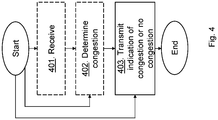
- the method actions in the radio network node for informing the network control node, such as the RNC 14, about the state of a connection between the radio network node and the user equipment 10 served by the radio network node according to some general embodiments will now be described with reference to a flowchart depicted in Fig. 4 .
- the actions do not have to be taken in the order stated below, but may be taken in any suitable order. Actions performed in some embodiments are marked with dashed boxes.
- the radio network node may receive data packets to distribute to the user equipment 10 within the cell served by the radio network node.
- the radio network node may determine whether a congestion over a radio interface towards the user equipment 10 exists or not. The congestion may be determined when MAC-hs or MAC-ehs packets congests a radio bearer towards the user equipment 10. In some embodiments the radio network node determines whether MAC-hs or MAC-ehs packets are queued over a first threshold or a delay of transmitting HARQ messages is over a second threshold. In some embodiments the radio network node may determine that the transport network between the radio network node and the network control node is congested based on received Delay Reference Time from the network control node.
- the radio network node transmits to the network control node, an indication indicating a congestion or not a congestion of MAC-hs or MAC-ehs packets towards the user equipment 10.
- the indication may further indicate a delay over the lub interface.
- the indication may comprise a bit indicating congestion of MAC-hs or MAC-ehs packets.
- the indication may comprise a first value indicating no congestion of MAC-hs or MAC-ehs packets or a second value indicating congestion of MAC-hs or MAC-ehs packets.
- the indication may additionally or alternatively comprise a value indicating congestion of MAC-hs or MAC-ehs packets due to a build-up buffer or a different value indicating congestion of MAC-hs or MAC-ehs packets due to frame drop.
- the indication may be comprised in a CA CF.
- the indication may be comprised in a spare extension field in the CA CF.
- the radio network node transmits queue length of MAC-hs or MAC-ehs packets and/or queue delay of MAC-hs or MAC-ehs packets.
- the indication may comprise the queue length or the queue length.
- the radio network node may transmit an additional indication indicating that a transport network between the radio network node and the network control node is congested, such as the delay over the lub interface.
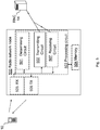
- FIG. 5 is block diagram depicting a radio network node 500, exemplified above as the first radio base station 12 or the second radio base station 13, for informing the network control node, such as the RNC 14, about the state of the connection between the radio network node 500 and the user equipment 10 served by the radio network node 500.
- the radio network node 500 is suitable for transmitting congestion information to the network control node. Circuits and units marked with dashed lines are comprised in some of the embodiments of the radio network node 500.
- the radio network node 500 may comprise a determining circuit 501 configured to determine whether a congestion over the radio interface towards the user equipment 10 exists or not. The congestion is determined when MAC-hs or MAC-ehs packets congests a radio bearer towards the user equipment 10.
- the determining circuit 501 may be configured to determine whether MAC-hs or MAC-ehs packets are queued over a first threshold or a delay of transmitting HARQ messages is over a second threshold.
- the determining circuit 501 may further be configured to determine that the transport network between the radio network node 500 and the network control node is congested based on received Delay Reference Time from the network control node.
- the radio network node 500 comprises a transmitting circuit 502 configured to transmit to the network control node, an indication indicating a congestion or not a congestion of MAC-hs or MAC-ehs packets towards the user equipment 10, or that the connection is congested or not to the network control node.
- the indication may further indicate a delay over the Iub interface.
- the indication may comprise a bit indicating congestion of MAC-hs or MAC-ehs packets.
- the indication may comprise the first value indicating no congestion of MAC-hs or MAC-ehs packets or the second value indicating congestion of MAC-hs or MAC-ehs packets.
- the indication may comprise a value indicating congestion of MAC-hs or MAC-ehs packets due to a build-up buffer or a different value indicating congestion of MAC-hs or MAC-ehs packets due to frame drop.
- the indication may be comprised in a CA CF.
- the indication may be comprised in a spare extension field in the CA CF.
- the transmitting circuit 502 may be configured to transmit queue length of MAC-hs or MAC-ehs packets and/or queue delay of MAC-hs or MAC-ehs packets. Alternatively or additionally, the transmitting circuit 502 may further be configured to transmit an additional indication indicating that the transport network between the radio network node 500 and the network control node is congested.
- the embodiments herein for informing connection state to the network control node may be implemented through one or more processors, such as a processing circuit 503 in the radio network node 500 depicted in Fig. 5 , together with computer program code for performing the functions and/or method actions of the embodiments herein.
- the program code mentioned above may also be provided as a computer program product, for instance in the form of a data carrier carrying computer program code for performing embodiments herein when being loaded into the radio network node.
- One such carrier may be in the form of a CD ROM disc. It is however feasible with other data carriers such as a memory stick.
- the computer program code may furthermore be provided as pure program code on a server and downloaded to the radio network node 500.
- the radio network node 500 further comprises a memory 504 that may comprise one or more memory units and may be used to store for example data such as packets, congestion information, applications to perform the methods herein when being executed on the network control node 500 or similar.
- the radio network node 500 further comprises a receiver 505 that may be configured to receive transmissions from the user equipment 10 and a transmitter 506 configured to transmit data to the user equipment 10.
- the data packets from the network control node may be received at a receiving circuit 507 comprised in the radio network node 500.
- the method actions in the network control node, referred to as the RNC 14 in the figures, for distributing a data packet towards the user equipment 10 via a first radio network node, such as the first radio base station 12, or a second network node, such as the second radio base station 13, according to some general embodiments will now be described with reference to a flowchart depicted in Fig. 6 .
- the actions do not have to be taken in the order stated below, but may be taken in any suitable order.
- the network control node receives an indication indicating a congestion or not a congestion of MAC-hs or MAC-ehs packets at the first radio network node or the second radio network node.
- the indication may comprise a bit indicating congestion or not of MAC-hs or MAC-ehs packets.
- the indication may comprise a first value indicating no congestion of MAC-hs or MAC-ehs packets or a second value indicating congestion of MAC-hs or MAC-ehs packets.
- the indication may comprise a value indicating congestion of MAC-hs or MAC-ehs packets due to build-up buffer or a different value indicating congestion of MAC-hs or MAC-ehs packets due to frame drop.
- the indication may further indicate a delay over the Iub interface.
- the delay over the lub interface may be defined as an explicit value or a value indicating different types of congestions.
- the indication may be comprised in a CA CF.
- the indication may for example be comprised in a spare extension field in the CA CF.
- the network control node may receive information of queue length of MAC-hs or MAC-ehs packets and/or queue delay of MAC-hs or MAC-ehs packets at the first radio network node or the second radio network node.
- the network control node receives an additional indication indicating that the transport network between the first or the second radio network node and the network control node is congested or a delay over the Iub interface.
- the additional indication may indicate a delay over the lub interface.
- the network control node distributes the data packet to the first radio network node or the second radio network node taking into account the received indication.
- the network control node may take the additional indication into account when distributing the data packets.
- the network control node may distribute data packets according to a weight distribution algorithm taking the indication and/or the additional indication into account.
- FIG. 7 is block diagram depicting a network control node 700, exemplified above as the RNC 14, for distributing a data packet or data packets towards the user equipment via the first radio network node or the second network node e.g. in a radio communications network. Circuits and units marked with dashed lines are comprised in some of the embodiments of the network control node 700.
- the network control node 700 comprises a receiving circuit 701 configured to receive the indication indicating a congestion or not a congestion of MAC-hs or MAC-ehs packets at the first radio network node or the second radio network node; in other words, that the connection to the user equipment 10 is congested or not of MAC-hs or MAC-ehs packets from the radio network node 500. This may be received from the respective radio network node.
- the indication may comprise the bit indicating congestion or not congestion of MAC-hs or MAC-ehs packets.
- the indication may comprise the first value indicating no congestion of MAC-hs or MAC-ehs packets or the second value indicating congestion of MAC-hs or MAC-ehs packets.
- the indication may comprise the value indicating congestion of MAC-hs or MAC-ehs packets due to build-up buffer or the different value indicating congestion of MAC-hs or MAC-ehs packets due to frame drop.
- the indication may further indicate by itself or in another field a delay over the Iub interface.
- the indication may be comprised in the CA CF.
- the indication may be comprised in a spare extension field in the CA CF.
- the receiving circuit 701 may be configured to receive information of queue length of MAC-hs or MAC-ehs packets and/or queue delay of MAC-hs or MAC-ehs packets at the first radio network node or the second radio network node.
- the receiving circuit 701 may further be configured to receive an additional indication indicating that the transport network the first or the second radio network node 12,13 and the network control node 700 is congested or a delay over the lub interface.
- the network control node 700 further comprises a scheduler 702, or a distributor, configured to distribute the data packet to the first radio network node or the second radio network node, that is, to the user equipment 10 via the radio network node 500 and/or another radio network node, taking into account the received indication.
- the distributor 702 may be configured to distribute data packets according to an algorithm, which algorithm takes the received indication into account.
- the scheduler 702 may be configured to take the additional indication into account.
- the scheduler 702 may be configured to schedule packets according to a weight distribution algorithm taking the indication and/or the additional indication into account.
- the packets may be distributed to a number of radio network nodes via a transmitting circuit 703.
- the embodiments herein for distributing the data packet may be implemented through one or more processors, such as a processing circuit 704 in the network control node 700 depicted in Fig. 7 , together with computer program code for performing the functions and/or method actions of the embodiments herein.
- the program code mentioned above may also be provided as a computer program product, for instance in the form of a data carrier carrying computer program code for performing embodiments herein when being loaded into the network control node 700.
- One such carrier may be in the form of a CD ROM disc. It is however feasible with other data carriers such as a memory stick.
- the computer program code may furthermore be provided as pure program code on a server and downloaded to the network control node 700.
- the network control node 700 further comprises a memory 705 that may comprise one or more memory units and may be used to store for example data such as scheduling algorithms, congestion information, application to perform the methods herein when being executed on the network control node 700 or similar.
- circuits may refer to a combination of analogue and digital circuits, and/or one or more processors configured with software and/or firmware (e.g., stored in memory) that, when executed by the one or more processors, perform as described above.
- processors as well as the other digital hardware, may be included in a single application-specific integrated circuit (ASIC), or several processors and various digital hardware may be distributed among several separate components, whether individually packaged or assembled into a system-on-a-chip (SoC).
- ASIC application-specific integrated circuit
- SoC system-on-a-chip
Landscapes
- Engineering & Computer Science (AREA)
- Computer Networks & Wireless Communication (AREA)
- Signal Processing (AREA)
- Databases & Information Systems (AREA)
- Mobile Radio Communication Systems (AREA)
- Data Exchanges In Wide-Area Networks (AREA)
Description
- Embodiments herein relate to a radio network node, a network control node and methods therein. In particular, embodiments herein relate to inform the network control node about a state of a connection in a radio communications network.
- In today's radio communications networks a number of different technologies are used, such as Long Term Evolution (LTE), LTE-Advanced, Wideband Code Division Multiple Access (WCDMA), Global System for Mobile communications/Enhanced Data rate for GSM Evolution (GSM/EDGE), Worldwide Interoperability for Microwave Access (WiMax), or Ultra Mobile Broadband (UMB), just to mention a few possible implementations. A radio communications network comprises Radio Base Stations (RBS) providing radio coverage over at least one respective geographical area forming a cell. The cell definition may also incorporate frequency bands used for transmissions, which means that two different cells may cover the same geographical area but using different frequency bands. User equipments (UE) are served in the cells by the respective radio base station and are communicating with respective radio base station. The user equipments transmit data over an air or radio interface to the radio base stations in uplink (UL) transmissions and the radio base stations transmit data over an air or radio interface to the user equipments in downlink (DL) transmissions. In e.g. High Speed Downlink Packet Access (HSDPA) systems a Radio Network Controller (RNC) may control the radio base stations.
- Recently, Multiflow transmission was proposed in 3rd Generation Partnership Project (3GPP) for HSDPA. For multiflow transmission when connections to the user equipment are via different RBSs, the flow has to be split in the RNC. The connections may be referred to as 'legs'. When HSDPA Flow Control is used in a traditional way the Capacity Allocation Control Frames (CA CF) define sending speed for both legs, which solves distribution of packets or Packet Data Units (PDU) among different legs. As HSDPA Flow Control is a proprietary solution and there may be other solutions, which do not only rely on credits indicated in High Speed-Downlink Shared Channel (HS-DSCH) CA CF. E.g. Active Queue Management (AQM) based congestion control solves flow control by propagating lub interface or Medium Access Control-high speed (MAC-hs) or Medium Access Control-enhanced high speed (MAC-ehs) loss to end-user Transport Control Protocol (TCP). The main idea of an AQM based flow control is that the application level TCP is reused as congestion control solution. When congestion is detected then the application level TCP is informed by an Internet Protocol (IP) packet drop. This packet drop will be noticed by TCP and the TCP will react on this loss with rate reduction. The lub interface connects the RBS and the RNC. The CA CF may include two Congestion Status Bits, however the values of these Congestion Status bits only indicate Transport Network Layer (TNL) congestion to be taken into account when distributing data to a user equipment still leading to a non-optimal packet distribution. Patent documents
US2008/186862A1 andWO2009/058085A2 disclose congestion control in high speed packet access radio networks. - An object according to some embodiments herein is for enabling improved data distribution in a radio communications network in an efficient manner.
- According to an aspect of embodiments herein, the object is achieved by a method performed by a radio network node according to claim 1. According to another aspect of embodiments herein, the object is achieved by a method performed by a network control node according to claim 11. According to yet another aspect of embodiments herein, the object is achieved by a radio network node according to claim 22. According to still another aspect of embodiments herein, the object is achieved by a network control node according to claim 32. Embodiments herein indicate congestion of MAC-hs or MAC-ehs packets towards the user equipment explicitly to the network control node. This has the advantage that it enables improved data distribution in the radio communications network in an efficient manner. E.g. is a connection to the user equipment via one of the radio network node congested of MAC-hs or MAC-ehs packets then less data packets are transmitted over that connection.
- Embodiments will now be described in more detail in relation to the enclosed drawings, in which:
- Fig. 1
- is a schematic overview depicting a radio communications network according to embodiments herein;
- Fig. 2
- is a combined schematic flowchart and signaling scheme according to embodiments herein;
- Fig. 3
- is a block diagram depicting embodiments herein;
- Fig. 4
- is a schematic flowchart of a method in a radio network node according to embodiments herein;
- Fig. 5
- is a block diagram depicting embodiments of a radio network node;
- Fig. 6
- is a schematic flowchart of a method in a network control node according to embodiments herein; and
- Fig. 7
- is a block diagram depicting embodiments of a network control node.
-
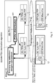
Fig. 1 is a schematic overview depicting a radio communications network 1 according to some embodiments herein. The radio communications network 1 may be a Wideband Code Division Multiple Access (WCDMA) network or a Global System for Mobile communications/Enhanced Data rate for GSM Evolution (GSM/EDGE) network just to mention a few possible implementations. The radio communications network 1 comprises a radio network node, a first radio network node referred herein as a firstradio base station 12, providing radio coverage over at least one geographical area forming a cell. The cell definition may also incorporate frequency bands used for transmissions, which means that two different cells may cover the same geographical area but using different frequency bands. Auser equipment 10 is served in the cell by the firstradio base station 12 and is communicating with the firstradio base station 12. It should be understood by the skilled in the art that "user equipment" is a non-limiting term which means any wireless terminal, device or node e.g. Personal Digital Assistant (PDA), laptop, mobile, sensor, relay, mobile tablets or even a small base station communicating within the cell. Theuser equipment 10 transmits data over an air or radio interface to the firstradio base station 12 in uplink (UL) transmissions and the firstradio base station 12 transmits data over an air or radio interface to theuser equipment 10 in downlink (DL) transmissions. Furthermore, the firstradio base station 12 is controlled by a network control node exemplified as anRNC 14 inFig. 1 . TheRNC 14 further controls a second radio network node referred herein as a secondradio base station 13. Theuser equipment 10 is also connected to the secondradio base station 13. Theuser equipment 10 receives data packets from the RNC via the firstradio base station 12 and via the secondradio base station 13 in a so called multiflow transmission procedure. The respective radio network node, above referred to asradio base stations radio base station - In a Radio Access Network (RAN) of the radio communications network 1, the congestion may occur (i) over the Transport Network (TN) that connects the
RNC 14 and respective radio base station, or (ii) in the firstradio base station 12 or the secondradio base station 13 when a capacity of a Uu interface towards theuser equipment 10 is smaller than the incoming bitrate to the firstradio base station 12 or the secondradio base station 13, in this case the length of MAC-hs packets or MAC-ehs packets in a queue is starting to increase. A MAC-hs layer or MAC-ehs layer is located in the respective radio base station and is responsible e.g. for scheduling, priority handling, Hybrid Automatic Repeat Request (HARQ), and selection of transport format and resources. An MAC-hs entity or MAC-ehs entity at respectiveradio base station user equipment 10. According to embodiments herein the firstradio base station 12 may detect or determine that MAC-hs or MAC-ehs packets are congested over the connection towards theuser equipment 10. The firstradio base station 12 then indicates to theRNC 14 whether MAC-hs or MAC-ehs congestion has been detected or not. The secondradio base station 13 may also indicate whether MAC-hs or MAC-ehs congestion has been detected or not to theRNC 14. TheRNC 14 may then, based on the received indication or indications, determine transmitting packets to theuser equipment 10 via the firstradio base station 12 or the secondradio base station 13. E.g. theRNC 14 may distribute the packets among the tworadio base stations user equipment 10 over one of theradio base stations user equipment 10. The congestion information of the MAC-hs or MAC-ehs layer is important input for the packet distribution algorithm in theRNC 14. Thus, theRNC 14 distributes data packets among controlled radio network nodes, such as the firstradio base station 12 and the secondradio base station 13, based on received indication or indications of MAC-hs or MAC-ehs congestion from respective radio network node. In some embodiments, more details about the nature of the congestion may further be sent to the network control node. -
Fig. 2 is a schematic combined flowchart and signaling scheme according to some embodiments in the radio communications network 1. The actions or steps may be performed in any suitable order. TheRNC 14 distributes data packets to theuser equipment 10 via the firstradio base station 12 and via the secondradio base station 13. E.g. initially data packets are equally distributed to theuser equipment 10 via the different connections. -
Action 201. TheRNC 14 sends data packets to the firstradio base station 12 to distribute to user equipments, e.g. theuser equipment 10, within the cell served by the firstradio base station 12. -
Action 202. The firstradio base station 12 may determine or detect whether a connection to theuser equipment 10 is congested of MAC-hs protocol transmissions, i.e. MAC-hs packets. E.g. if MAC-hs packets, also referred to as MAC-hs protocol packets or MAC-hs protocol layer packets, are queued over a certain threshold level or a delay of transmitting HARQ messages is over a certain threshold a congestion is detected. A queue may be measured by a number of PDUs of the Mac-hs protocol layer or time in queue of PDUs. Such PDUs comprise e.g. user traffic such as TCP data and TCP Acknowledgements (ACK). The MAC-hs queue may be per Radio Bearer and a MAC-hs radio bearer may be associated with one user equipment e.g. theuser equipment 10. It should be noted that theuser equipment 10 may have more than one radio bearer carrying data. -
Action 203. The firstradio base station 12 transmits to theRNC 14, an indication indicating a congestion or not a congestion of MAC-hs packets towards theuser equipment 10. The indication thus indicates whether the connection to theuser equipment 10 is MAC-hs packets congested or not. The indication may be transmitted in the HS-DSCH Capacity Allocation Control Frame (CA CF). Furthermore, the indication may further also indicate whether congestion over the transport network is present. -
Action 204. Additionally or alternatively, theRNC 14 sends data packets to the secondradio base station 13 to distribute to user equipments, e.g. theuser equipment 10, within the cell served by the secondradio base station 13. -
Action 205. The secondradio base station 13 detects whether a connection to theuser equipment 10 is congested of MAC-hs layer transmissions towards theuser equipment 10. E.g. if MAC-hs protocol packets are queued over a certain threshold level or a delay of transmitting HARQ messages is over a certain threshold a congestion is determined. -
Action 206. The secondradio base station 13 transmits an indication indicating whether connection is MAC-hs protocol congested or not. The indication may be transmitted in the HS-DSCH CA CF. -
Action 207. TheRNC 14 may then distribute data packets or PDUs taking the received indications from respectiveradio base station RNC 14 receives data packets and theRNC 14 decides e.g. what leg, meaning connection to theuser equipment 10 via either the first or the secondradio base station station 12 and another half over the second radio base-station 13. Of course both radio base-stations RNC 14 has some information about congestion status of MAC-hs packets of the used legs then instead of e.g. the 50-50% division it may use a more efficient solution, e.g. less packets are transmitted over a congested leg. It should be noted that MAC-hs packets are used in this illustrative example but MAC-ehs packets may alternatively be used in similar embodiments. - As stated above, the indication may be transmitted in the HS-DSCH CA CF. Section "6.3.3.11 HS-DSCH CAPACITY ALLOCATION" in 3GPP TS 25.435 V10.2.0 (2011-06) describes the CA CF. Two types of HS-DSCH CAPACITY ALLOCATION exist for the HS-DSCH capacity allocation, i.e. HS-DSCH CAPACITY ALLOCATION TYPE 1 Control Frame and HS-DSCH CAPACITY ALLOCATION TYPE 2 Control Frame.
7... 0 Spare bits 7-6 Congestion Status CmCH-PI Maximum MAC-d PDU Length Maximum MAC-d PDU Length (cont) HS-DSCH Credits HS-DSCH Credits (cont) HS-DSCH Interval HS-DSCH Repetition Period Spare Extension - The CAPACITY ALLOCATION TYPE 1 Control Frame describes an allocation that the
RNC 14, also referred to as a Controlling RNC CRNC, may use. Each octet of bits comprises 8 bits that are indexed from 7-0. When the High Speed - Downlink Shared Channel (HS-DSCH) Credits Information Element (IE) has a value of 0, it signifies that there is no resources allocated for transmission and to thus stop transmission. When the HS-DSCH Credits IE has a value of 2047, it signifies unlimited capacity for transmission of PDUs. When the HS-DSCH Repetition Period IE has a value of 0, it signifies that the allocation, Maximum MAC-d PDU Length, HS-DSCH Credits and HS-DSCH Interval IEs, may be repeated without limit. In addition to this the CAPACITY ALLOCATION TYPE 1 Control Frame informs theRNC 14 about the detection of congestion in the DL transport network layer with Congestion Status Bits. Common Transport Channel Priority Indicator (CmCH-PI) is a relative priority of the
data frame and SDUs therein included.7... 0 Spare bits 7-6 Congestion Status CmCH-PI Spare bits Max. MAC-d/c PDU Length Maximum MAC-d/c PDU Length (cont) HS-DSCH Credits HS-DSCH Credits (cont) HS-DSCH Interval HS-DSCH Repetition Period Spare Extension - The CAPACITY ALLOCATION TYPE 2 Control Frame describes an allocation that the
RNC 14 may use. Each octet of bits comprises 8 bits that are indexed from 7-0. When the HS-DSCH Credits IE has a value of 0 it signifies that there is no resources allocated for transmission and to thus stop transmission. When the HS-DSCH Credits IE has a value of 65535, it signifies unlimited capacity for transmission of PDUs. When the HS-DSCH Repetition Period IE has a value of 0, it signifies that the allocation (Maximum MAC-d/c PDU Length, HS-DSCH Credits and HS-DSCH Interval IEs) may be repeated without limit. In addition to this the CAPACITY ALLOCATION TYPE 2 Control Frame informs theRNC 14 about the detection of congestion in the DL transport network layer with the Congestion Status Bits. CmCH-PI is the relative priority of the
data frame and SDUs therein included. - Maximum MAC-d PDU Length IE is used in HS-DSCH CAPACITY ALLOCATION TYPE 1 Control Frame. The value indicates the maximum allowable PDU size among the MAC-d PDU sizes configured via Node B Application Part (NBAP), which is a signalling protocol responsible for the control of the Node B by the
RNC 14. - HS-DSCH Credits IE is used in HS-DSCH CAPACITY ALLOCATION (TYPE 1 and TYPE 2) Control Frame. It indicates the granted amount of MAC-d PDU data that the
RNC 14 may transmit during one HD-DSCH interval. In case of HS-DSCH CAPACITY ALLOCATION TYPE 1 Control Frame, it indicates the number of MAC-d PDUs that aRNC 14 may transmit during one HS-DSCH Interval granted in the HS-DSCH CAPACITY ALLOCATION TYPE 1 Control Frame. In case of HS-DSCH CAPACITY ALLOCATION TYPE 2 Control Frame, the granted amount of MAC-d [Frequency Division Duplexing (FDD) and 1.28Mcps Time Division Duplexing (TDD) - or MAC-c] PDU data in octets is obtained by multiplying the MAC-d PDU length [FDD and 1.28Mcps TDD - or the MAC-c PDU length], indicated by the Maximum MAC- d/c PDU Length IE, with the number of MAC-d PDUs [FDD and 1.28Mcps TDD - or MAC-c PDUs], indicated by the HS-DSCH Credits IE.
Value range: {0-2047, where 0=stop transmission, 2047=unlimited} in case of HS-DSCH CAPACITY ALLOCATION TYPE 1 Control Frame, {0-65535, where 0=stop transmission, 65535=unlimited} in case of HS-DSCH CAPACITY ALLOCATION TYPE 2 Control Frame.
Field length: 11 bits in case of HS-DSCH CAPACITY ALLOCATION TYPE 1 Control Frame, 16 bits in case of HS-DSCH CAPACITY ALLOCATION TYPE 2 Control Frame. - HS-DSCH Interval; the value of this field indicates the time interval during which the HS-DSCH Credits granted in the HS-DSCH CAPACITY ALLOCATION (TYPE 1 or TYPE 2) Control Frame may be used. The first interval starts immediately after reception of the HS-DSCH CAPACITY ALLOCATION (TYPE 1 or TYPE 2) Control Frame, subsequent intervals start immediately after the previous interval has elapsed. This value is only applied to the HS-DSCH transport channel.
Value range: {0-2550 ms}. Value 0 shall be interpreted that none of the credits shall be used.
Granularity: 10ms.
Field Length: 8 bits. - HS-DSCH Repetition Period; the value of this field indicates the number of subsequent intervals that the HS-DSCH Credits IE granted in the HS-DSCH CAPACITY ALLOCATION (TYPE 1 or TYPE 2) Control Frame may be used. These values represent an integer number of Intervals. This field is only applied to the HS-DSCH transport channel.
Value range: {0-255, where 0= unlimited repetition period}.
Field Length: 8 bits. - Spare Extension. Bits spared to define an extension of an IE or a new IE.
- The Congestion Status Bits are used by the first
radio base station 12 to indicate whether a congestion situation is detected in a DL transport network layer or not. The firstradio base station 12 provides the congestion status in every HS-DSCH CAPACITY ALLOCATION (TYPE 1 or TYPE 2) Control Frame, which theRNC 14 may use. -
- 0
- No TNL Congestion
- 1
- Reserved for future use
- 2
- TNL Congestion - detected by delay build-up
- 3
- TNL Congestion - detected by frame loss
- The Maximum MAC-d/c PDU Length IE is used in HS-DSCH CAPACITY ALLOCATION TYPE 2 Control Frame. The value is a factor in the granted amount of MAC-d PDU data that the
RNC 14 may transmit during one HS-DSCH Interval. The amount of MAC-d [FDD and 1.28Mcps TDD - or MAC-c ] PDU data in octets is obtained by multiplying the MAC-d [FDD and 1.28Mcps TDD - or MAC-c ] PDU length, indicated by the Maximum MAC d/c PDU Length IE, with the number of MAC-d PDUs [FDD and 1.28Mcps TDD - or MAC-c PDUs], indicated by the HS-DSCH Credits IE.
Value range: {0-1505}, 0 - not used.
Field length: 11 bits. - Embodiments herein provide following solutions to indicate MAC-hs congestion:
- Use Congestion status value 1, reserved for future use, to indicate MAC-hs congestion.
- Introduce a 2-bit "MAC-hs congestion status"
- A value (0) for no MAC-hs congestion, a different value (1) for MAC-hs congestion
- A value (0) for no MAC-hs congestion, a different value (1) for MAC-hs congestion due to buffer buildup, a different value for frame drop (2)
- Rely on the information about MAC-hs queue length and MAC-hs queue delay to determine MAC-hs congestion.
- As "Congestion status value 1" may be needed for different type of TNL congestion and as TNL and MAC-hs congestion may in theory happen at the same time, using Use Congestion status value 1 is not recommended as that would omit the possibility to indicate both TNL and MAC-hs congestion.
- For some PDU distribution algorithms it may be advantageous to have detailed information about the status of the MAC-hs scheduling buffer. The following information is possible. The fields, described below, may be added to the spare extension part of the CA CF, and might not be sent in every CA CF. These fields may indicate an instantaneous value or an averaged value. The condition when to send this information may vary between different vendors.
- In some embodiments the indication comprises MAC-hs queue length. Description: The length of the MAC-hs queue in octets. Value range: 3 * 8 bits (determined based on max. SDU size = 1500 octets and max RLC window).
- In some embodiments the indication comprises MAC-hs queue delay. Description: The delay experienced by the most delayed PDU in the queue (normally the first). Value Range: 0-500 ms, (9 bits needed for 1 ms granularity, 8 bits are OK for 2 ms granularity)
- In IP based TN, Explicit Congestion Notification (ECN) may also be used for congestion detection. While congestion status values'2', which defines "TNL congestion - detected by delay build-up", may be used to indicate congestion detected by ECN, it may be advantageous to differentiate ECN type of congestion. A solution for that is to use congestion Status 1 to indicate "TNL Congestion - detected by ECN".
- In 3GPP TS 25.435 V10.2.0 (2011-06) HS-DSCH DATA FRAME type 1 and 2 "HS-DSCH Channels" includes Delay Reference Time (DRT). If DRT is included often enough, maybe in each HS-DSCH DATA FRAME from the
RNC 14 to the firstradio base station 12, then the dynamic delay over a lub may be measured at the firstradio base station 12 and used for PDU distribution inRNC 14. The DRT may be used to estimate the actual TN delay; e.g. packet delay betweenRNC 14 and the firstradio base station 12. In theRNC 14 we add time-stamps to the packets, based on these time-stamps the firstradio base station 12 may estimate the delay of the packet. When DRT is used then the firstradio base station 12 may provide a bit detailed information about the TN congestion status. - The following optional data frame field is proposed to be introduced.
- 'lub dynamic delay'. Description: The delay experienced by HS-DSCH DATA FRAME in TNL. Value Range: 0-500 ms, (9 bits needed for 1 ms granularity, 8 bits are OK for 2 ms granularity)
- A bitmask may be introduced in the spare extension part of CA CF to indicate whether the given information is present for the following fields: MAC-hs queue length; MAC-hs queue delay; and/or lub dynamic delay.
- Thus, embodiments above describe different ways of indicating, to the
RNC 14, the congestion of MAC-hs packets towards theuser equipment 10, but also TN congestion. -
FIG. 3 is a block diagram depicting embodiments herein. An HSDPA architecture splits a MAC layer between theRNC 14 and the radio network node e.g. the firstradio base station 12. MAC PDUs that are generated by theRNC 14 and referred to as MAC-d PDUs, are aggregated and sent to the radio network node over a Iub interface using HS-DSCH frames; Iub Frame Protocol (FP) 300,301. A Radio Link Control (RLC)layer 302 at theRNC 14 is segmenting and responsible for retransmissions of user data and control data on the downlink. TheRLC layer 302 is involved in a data link layer retransmission process when the HARQ fails or exceeds number of retransmissions. A MAC-d layer entity RNC 14 to handle transport channel switching. A MAC-hs layer entity 305 is located in the firstradio base station 12 and a MAC-hs layer entity 306 is located in the secondradio base station 13. The MAC-hs entity 305,306 is responsible for scheduling, priority handling, HARQ, and selection of an appropriate transport format and resources. For an HSDPA connection, data received from a core network is encapsulated in a MAC-d PDU and then transmitted over the Iub interfacein an HS-DSCH frame format to Iub FP 307,308. The MAC-hs entity 305,306 in the first or secondradio base station user equipment 10, That is, the PDUs of the Mac-hs protocol layer. This comprises the user traffic, e.g. TCP data and TCP Acknowledgements (ACKs). - In the
radio network nodes RNC 14. Based on this information aPDU distributor 311, referred to below as a scheduler, updates its status. For example, if the firstradio base station 12 signals back MAC-hs congestion then less data packets will be transmitted over the firstradio base station 12 towards theuser equipment 10. For example there are two legs and a Weight_first=10% is used in theRNC 14 when MAC-hs congestion is reported from the firstradio base station 12. Then 90% of the RLC PDUs are transmitted over a secondary leg to the secondradio base station 13 and the remaining 10% over the first leg to the firstradio base station 12. Analgorithm 312 takes indication of MAC-hs congestion into account when performing primary leg selection, and weight calculation, which is used to update PDU distribution algorithm. As stated above it should be noted that MAC-hs packets are used in this illustrative example but MAC-ehs packets may alternatively be used in similar embodiments. - The object of distributing data packets in an efficient manner may be achieved according to embodiments herein by a method in a radio network node, such as the first
radio base station 12, for informing the network control node, such as theRNC 14, about a state of a connection between the firstradio base station 12 and theuser equipment 10 served by the firstradio base station 12. The firstradio base station 12 may determine whether a congestion over an air interface towards theuser equipment 10 exists. For example, MAC-hs protocol layer packets congesting a radio bearer towards theuser equipment 10. The firstradio base station 12 then transmits to theRNC 14 an indication indicating that a congestion is determined or not. Some embodiments herein include a possibility to indicate MAC-hs congestion in e.g. the CA CF. Optionally also indicate MAC-hs queue length and MAC-hs queue delay in the CA CF. Optionally the firstradio base station 12 may also indicate lub Frame Protocol (FP) Data Frame Dynamic Delay in the CA CF. The extra indicated congestion information may be utilized in a data packet or PDU distribution algorithm such as a weight distribution algorithm in theRNC 14. Thus, an addition of a congestion indication in the CA CF is available and more information is available for the purposes of packet or PDU distribution. In the current solution only the Transport Network (TN) congestion can be signaled back to theRNC 14. Embodiments herein signal back Mac-hs related congestion, when e.g. the Mac-hs queue is getting too long. - According to embodiments herein the object may further be achieved by a method in a network control node such as the
RNC 14 for distributing data packets in a radio communications network. TheRNC 14 receives an indication from e.g. the firstradio base station 12 indicating a congestion or not a congestion of packets, such as MAC-hs packets, over an air interface towards theuser equipment 10 served by the radio network node. TheRNC 14 controls at least the radio network node and another radio network node, e.g. the first and secondradio base station user equipment 10 via the respective radio network node in a multi flow manner. TheRNC 14 decides scheduling data packets towards theuser equipment 10 via the radio network node and/or the other radio network node based on the received indication. For example, theRNC 14 takes the indication into account when selecting transmission path to theuser equipment 10 for data packets. - The method actions in the radio network node, referred to as the first
radio base station 12 or the secondradio base station 13 in the figures, for informing the network control node, such as theRNC 14, about the state of a connection between the radio network node and theuser equipment 10 served by the radio network node according to some general embodiments will now be described with reference to a flowchart depicted inFig. 4 . The actions do not have to be taken in the order stated below, but may be taken in any suitable order. Actions performed in some embodiments are marked with dashed boxes. -
Action 401. The radio network node may receive data packets to distribute to theuser equipment 10 within the cell served by the radio network node. -
Action 402. The radio network node may determine whether a congestion over a radio interface towards theuser equipment 10 exists or not. The congestion may be determined when MAC-hs or MAC-ehs packets congests a radio bearer towards theuser equipment 10. In some embodiments the radio network node determines whether MAC-hs or MAC-ehs packets are queued over a first threshold or a delay of transmitting HARQ messages is over a second threshold. In some embodiments the radio network node may determine that the transport network between the radio network node and the network control node is congested based on received Delay Reference Time from the network control node. -
Action 403. The radio network node transmits to the network control node, an indication indicating a congestion or not a congestion of MAC-hs or MAC-ehs packets towards theuser equipment 10. The indication may further indicate a delay over the lub interface. The indication may comprise a bit indicating congestion of MAC-hs or MAC-ehs packets. The indication may comprise a first value indicating no congestion of MAC-hs or MAC-ehs packets or a second value indicating congestion of MAC-hs or MAC-ehs packets. The indication may additionally or alternatively comprise a value indicating congestion of MAC-hs or MAC-ehs packets due to a build-up buffer or a different value indicating congestion of MAC-hs or MAC-ehs packets due to frame drop. The indication may be comprised in a CA CF. For example; the indication may be comprised in a spare extension field in the CA CF. In some embodiments the radio network node transmits queue length of MAC-hs or MAC-ehs packets and/or queue delay of MAC-hs or MAC-ehs packets. Thus, the indication may comprise the queue length or the queue length. The radio network node may transmit an additional indication indicating that a transport network between the radio network node and the network control node is congested, such as the delay over the lub interface. -
FIG. 5 is block diagram depicting aradio network node 500, exemplified above as the firstradio base station 12 or the secondradio base station 13, for informing the network control node, such as theRNC 14, about the state of the connection between theradio network node 500 and theuser equipment 10 served by theradio network node 500. Thus, theradio network node 500 is suitable for transmitting congestion information to the network control node. Circuits and units marked with dashed lines are comprised in some of the embodiments of theradio network node 500. - The
radio network node 500 may comprise a determiningcircuit 501 configured to determine whether a congestion over the radio interface towards theuser equipment 10 exists or not. The congestion is determined when MAC-hs or MAC-ehs packets congests a radio bearer towards theuser equipment 10. The determiningcircuit 501 may be configured to determine whether MAC-hs or MAC-ehs packets are queued over a first threshold or a delay of transmitting HARQ messages is over a second threshold. The determiningcircuit 501 may further be configured to determine that the transport network between theradio network node 500 and the network control node is congested based on received Delay Reference Time from the network control node. - Furthermore, the
radio network node 500 comprises a transmittingcircuit 502 configured to transmit to the network control node, an indication indicating a congestion or not a congestion of MAC-hs or MAC-ehs packets towards theuser equipment 10, or that the connection is congested or not to the network control node. The indication may further indicate a delay over the Iub interface. The indication may comprise a bit indicating congestion of MAC-hs or MAC-ehs packets. The indication may comprise the first value indicating no congestion of MAC-hs or MAC-ehs packets or the second value indicating congestion of MAC-hs or MAC-ehs packets. The indication may comprise a value indicating congestion of MAC-hs or MAC-ehs packets due to a build-up buffer or a different value indicating congestion of MAC-hs or MAC-ehs packets due to frame drop. The indication may be comprised in a CA CF. The indication may be comprised in a spare extension field in the CA CF. The transmittingcircuit 502 may be configured to transmit queue length of MAC-hs or MAC-ehs packets and/or queue delay of MAC-hs or MAC-ehs packets. Alternatively or additionally, the transmittingcircuit 502 may further be configured to transmit an additional indication indicating that the transport network between theradio network node 500 and the network control node is congested. - The embodiments herein for informing connection state to the network control node may be implemented through one or more processors, such as a
processing circuit 503 in theradio network node 500 depicted inFig. 5 , together with computer program code for performing the functions and/or method actions of the embodiments herein. The program code mentioned above may also be provided as a computer program product, for instance in the form of a data carrier carrying computer program code for performing embodiments herein when being loaded into the radio network node. One such carrier may be in the form of a CD ROM disc. It is however feasible with other data carriers such as a memory stick. The computer program code may furthermore be provided as pure program code on a server and downloaded to theradio network node 500. Theradio network node 500 further comprises a memory 504 that may comprise one or more memory units and may be used to store for example data such as packets, congestion information, applications to perform the methods herein when being executed on thenetwork control node 500 or similar. - Additionally, the
radio network node 500 further comprises areceiver 505 that may be configured to receive transmissions from theuser equipment 10 and atransmitter 506 configured to transmit data to theuser equipment 10. The data packets from the network control node may be received at a receivingcircuit 507 comprised in theradio network node 500. - The method actions in the network control node, referred to as the
RNC 14 in the figures, for distributing a data packet towards theuser equipment 10 via a first radio network node, such as the firstradio base station 12, or a second network node, such as the secondradio base station 13, according to some general embodiments will now be described with reference to a flowchart depicted inFig. 6 . The actions do not have to be taken in the order stated below, but may be taken in any suitable order. -
Action 601. The network control node receives an indication indicating a congestion or not a congestion of MAC-hs or MAC-ehs packets at the first radio network node or the second radio network node. The indication may comprise a bit indicating congestion or not of MAC-hs or MAC-ehs packets. The indication may comprise a first value indicating no congestion of MAC-hs or MAC-ehs packets or a second value indicating congestion of MAC-hs or MAC-ehs packets. The indication may comprise a value indicating congestion of MAC-hs or MAC-ehs packets due to build-up buffer or a different value indicating congestion of MAC-hs or MAC-ehs packets due to frame drop. The indication may further indicate a delay over the Iub interface. The delay over the lub interface may be defined as an explicit value or a value indicating different types of congestions. The indication may be comprised in a CA CF. The indication may for example be comprised in a spare extension field in the CA CF. The network control node may receive information of queue length of MAC-hs or MAC-ehs packets and/or queue delay of MAC-hs or MAC-ehs packets at the first radio network node or the second radio network node. In some embodiments the network control node receives an additional indication indicating that the transport network between the first or the second radio network node and the network control node is congested or a delay over the Iub interface. The additional indication may indicate a delay over the lub interface. -
Action 602. The network control node distributes the data packet to the first radio network node or the second radio network node taking into account the received indication. The network control node may take the additional indication into account when distributing the data packets. The network control node may distribute data packets according to a weight distribution algorithm taking the indication and/or the additional indication into account. -
FIG. 7 is block diagram depicting anetwork control node 700, exemplified above as theRNC 14, for distributing a data packet or data packets towards the user equipment via the first radio network node or the second network node e.g. in a radio communications network. Circuits and units marked with dashed lines are comprised in some of the embodiments of thenetwork control node 700. - The
network control node 700 comprises a receivingcircuit 701 configured to receive the indication indicating a congestion or not a congestion of MAC-hs or MAC-ehs packets at the first radio network node or the second radio network node; in other words, that the connection to theuser equipment 10 is congested or not of MAC-hs or MAC-ehs packets from theradio network node 500. This may be received from the respective radio network node. The indication may comprise the bit indicating congestion or not congestion of MAC-hs or MAC-ehs packets. The indication may comprise the first value indicating no congestion of MAC-hs or MAC-ehs packets or the second value indicating congestion of MAC-hs or MAC-ehs packets. The indication may comprise the value indicating congestion of MAC-hs or MAC-ehs packets due to build-up buffer or the different value indicating congestion of MAC-hs or MAC-ehs packets due to frame drop. The indication may further indicate by itself or in another field a delay over the Iub interface. The indication may be comprised in the CA CF. The indication may be comprised in a spare extension field in the CA CF. The receivingcircuit 701 may be configured to receive information of queue length of MAC-hs or MAC-ehs packets and/or queue delay of MAC-hs or MAC-ehs packets at the first radio network node or the second radio network node. The receivingcircuit 701 may further be configured to receive an additional indication indicating that the transport network the first or the secondradio network node network control node 700 is congested or a delay over the lub interface. - The
network control node 700 further comprises ascheduler 702, or a distributor, configured to distribute the data packet to the first radio network node or the second radio network node, that is, to theuser equipment 10 via theradio network node 500 and/or another radio network node, taking into account the received indication. Thedistributor 702 may be configured to distribute data packets according to an algorithm, which algorithm takes the received indication into account. Thescheduler 702 may be configured to take the additional indication into account. Thescheduler 702 may be configured to schedule packets according to a weight distribution algorithm taking the indication and/or the additional indication into account. - The packets may be distributed to a number of radio network nodes via a transmitting
circuit 703. - The embodiments herein for distributing the data packet may be implemented through one or more processors, such as a
processing circuit 704 in thenetwork control node 700 depicted inFig. 7 , together with computer program code for performing the functions and/or method actions of the embodiments herein. The program code mentioned above may also be provided as a computer program product, for instance in the form of a data carrier carrying computer program code for performing embodiments herein when being loaded into thenetwork control node 700. One such carrier may be in the form of a CD ROM disc. It is however feasible with other data carriers such as a memory stick. The computer program code may furthermore be provided as pure program code on a server and downloaded to thenetwork control node 700. Thenetwork control node 700 further comprises a memory 705 that may comprise one or more memory units and may be used to store for example data such as scheduling algorithms, congestion information, application to perform the methods herein when being executed on thenetwork control node 700 or similar. - Those skilled in the art will also appreciate that the various "circuits" described may refer to a combination of analogue and digital circuits, and/or one or more processors configured with software and/or firmware (e.g., stored in memory) that, when executed by the one or more processors, perform as described above. One or more of these processors, as well as the other digital hardware, may be included in a single application-specific integrated circuit (ASIC), or several processors and various digital hardware may be distributed among several separate components, whether individually packaged or assembled into a system-on-a-chip (SoC).
- Modifications and other embodiments of the disclosed example(s) will come to mind to one skilled in the art having the benefit of the teachings presented in the foregoing descriptions and the associated drawings. Therefore, it is to be understood that the embodiment(s) is/are not to be limited to the specific embodiments disclosed and that modifications and other embodiments are intended to be included within the scope of this disclosure. Although specific terms may be employed herein, they are used in a generic and descriptive sense only and not for purposes of limitation.
Claims (42)
- A method performed by a radio network node (500,12,13) for informing a network control node (700,14) about a state of a connection between the radio network node (500,12,13) and a user equipment (10) served by the radio network node (500,12,13), the method comprising:- transmitting (203,206,403) to the network control node (700,14) an indication indicating a congestion or not a congestion of Medium Access Control-high speed, MAC-hs, or Medium Access Control-enhanced high speed, MAC-ehs, packets towards the user equipment (10),and- determining (202,205,402) whether the congestion over a radio interface towards the user equipment (10) exists or not, wherein the congestion is determined when MAC-hs or MAC-ehs packets congests a radio bearer towards the user equipment (10),wherein the determining (202,205,402) comprises to determine whether MAC-hs or MAC-ehs packets are queued over a first threshold or a delay of transmitting Hybrid Automatic Repeat Request, HARQ, messages is over a second threshold.
- A method according to claim 1, wherein the indication further indicates a delay over a lub interface.
- A method according to claim 1 or 2, wherein the indication comprises a bit indicating congestion of MAC-hs or MAC-ehs packets.
- A method according to any of the claims 1-3, wherein the indication comprises a first value indicating no congestion of MAC-hs or MAC-ehs packets or a second value indicating congestion of MAC-hs or MAC-ehs packets.
- A method according to any of the claims 1-4, wherein the indication comprises a value indicating congestion of MAC-hs or MAC-ehs packets due to a build-up buffer or a different value indicating congestion of MAC-hs or MAC-ehs packets due to frame drop.
- A method according to any of the claims 1-5, wherein the indication is comprised in a Capacity Allocation Control Frame.
- A method according to claim 6, wherein the indication is comprised in a spare extension field in the Capacity Allocation Control Frame.
- A method according to any of the claims 1-7, wherein the transmitting (203,206,403) comprises to transmit queue length of MAC-hs or MAC-ehs packets and/or queue delay of MAC-hs or MAC-ehs packets.
- A method according to any of the claims 1-8, wherein the transmitting (203,206,403) further comprises to transmit an additional indication that a transport network between the radio network node (500,12,13) and the network control node (700,14) is congested.
- A method according to claims 1 and 9, wherein the determining (202,205,402) further comprises to determine that the transport network between the radio network node (500,12,13) and the network control node (700,14) is congested based on received Delay Reference Time from the network control node (700,14).
- A method performed by a network control node (700,14) for distributing a data packet towards a user equipment (10) via a first radio network node (12) or a second radio network node (13), the method comprising:- receiving (601) an indication indicating a congestion or not a congestion of Medium Access Control-high speed, MAC-hs, or Medium Access Control-enhanced high speed, MAC-ehs, packets at the first radio network node (12) or the second radio network node (13), wherein the congestion was determined when MAC-hs or MAC-ehs packets congest a radio bearer towards the user equipment (10), and MAC-hs packets or MAC-ehs packets was queued over a first threshold or a delay of transmitting Hybrid Automatic Repeat Request, HARQ, messages was over a second threshold; and- distributing (207,602) the data packet to the first radio network node (12) or the second radio network node (13) taking into account the received indication.
- A method according to claim 11, wherein the indication comprises a bit indicating congestion or not of MAC-hs or MAC-ehs packets.
- A method according to claim 11 or 12, wherein the indication comprises a first value indicating no congestion of MAC-hs or MAC-ehs packets or a second value indicating congestion of MAC-hs or MAC-ehs packets.
- A method according to any of the claims 11-13, wherein the indication comprises a value indicating congestion of MAC-hs or MAC-ehs packets due to build-up buffer or a different value indicating congestion of MAC-hs or MAC-ehs packets due to frame drop.
- A method according to any of the claims 11-14, wherein the indication further indicates a delay over a Iub interface.
- A method according to any of the claims 11-15, wherein the indication is comprised in a Capacity Allocation Control Frame.
- A method according to claim 16, wherein the indication is comprised in a spare extension field in the Capacity Allocation Control Frame.
- A method according to any of the claims 11-17, wherein the receiving (601) comprises to receive information of queue length of MAC-hs or MAC-ehs packets and/or queue delay of MAC-hs or MAC-ehs packets at the first radio network node (12) or the second radio network node (13).
- A method according to any of the claims 11-18, wherein the receiving (601) further comprises to receive an additional indication indicating that a transport network between the first or the second radio network node (12,13) and the network control node (700,14) is congested or a delay over a Iub interface.
- A method according to claim 19, wherein the distributing (207,602) further takes the additional indication into account.
- A method according to any of the claims 11-20, wherein the distributing (207,602) is performed according to a weight distribution algorithm taking the indication and/or the additional indication into account.
- A radio network node (500,12,13) for informing a network control node (700,14) about a state of a connection between the radio network node (500,12,13) and a user equipment (10) served by the radio network node (500,12,13), comprising:a transmitting circuit (502) configured to transmit to the network control node (700,14), an indication indicating a congestion or not a congestion of Medium Access Control-high speed, MAC-hs, or Medium Access Control-enhanced high speed, MAC-ehs, packets towards the user equipment (10),a determining circuit (501) configured to determine whether a congestion over a radio interface towards the user equipment (10) exists or not, wherein the congestion is determined when MAC-hs or MAC-ehs packets congests a radio bearer towards the user equipment (10),wherein the determining circuit (501) is configured to determine whether MAC-hs or MAC-ehs packets are queued over a first threshold or a delay of transmitting Hybrid Automatic Repeat Request, HARQ, messages is over a second threshold.
- A radio network node (500,12,13) according to claim 22, wherein the indication further indicates a delay over a Iub interface.
- A radio network node (500,12,13) according to claims 22 or 23, wherein the indication comprises a bit indicating congestion of MAC-hs or MAC-ehs packets.
- A radio network node (500,12,13) according to any of the claims 22-24, wherein the indication comprises a first value indicating no congestion of MAC-hs or MAC-ehs packets or a second value indicating congestion of MAC-hs or MAC-ehs packets.
- A radio network node (500,12,13) according to any of the claims 22-25, wherein the indication comprises a value indicating congestion of MAC-hs or MAC-ehs packets due to a build-up buffer or a different value indicating congestion of MAC-hs or MAC-ehs packets due to frame drop.
- A radio network node (500,12,13) according to any of the claims 22-26, wherein the indication is comprised in a Capacity Allocation Control Frame.
- A radio network node (500,12,13) according to claim 27, wherein the indication is comprised in a spare extension field in the Capacity Allocation Control Frame.
- A radio network node (500,12,13) according to any of the claims 22-28, wherein the transmitting circuit (502) is configured to transmit queue length of MAC-hs or MAC-ehs packets and/or queue delay of MAC-hs or MAC-ehs packets.
- A radio network node (500,12,13) according to any of the claims 22-29, wherein the transmitting circuit (502) is further configured to transmit an additional indication indicating that a transport network between the radio network node (12) and the network control node (14) is congested.
- A radio network node (500,12,13) according to claims 22 and 30, wherein the determining circuit (501) is further configured to determine that the transport network between the radio network node (500,12,13) and the network control node (700,14) is congested based on received Delay Reference Time from the network control node (700,14).
- A network control node (700,14) for distributing a data packet towards a user equipment (10) via a first radio network node (12) or a second network node (13), comprising:a receiving circuit (701) configured to receive an indication indicating a congestion or not a congestion of Medium Access Control-high speed, MAC-hs, or Medium Access Control-enhanced high speed, MAC-ehs, packets at the first radio network node (12) or the second radio network node (13), wherein the congestion was determined when MAC-hs or MAC-ehs packets congest a radio bearer towards the user equipment (10), and MAC-hs packets or MAC-ehs packets was queued over a first threshold or a delay of transmitting Hybrid Automatic Repeat Request, HARQ, messages was over a second threshold; anda scheduler (702) configured to distribute the data packet to the first radio network node (12) or the second radio network node (13) taking into account the received indication.
- A network control node (700,14) according to claim 32, wherein the indication comprises a bit indicating congestion or not congestion of MAC-hs or MAC-ehs packets.
- A network control node (700,14) according to claim 32 or 33, wherein the indication comprises a first value indicating no congestion of MAC-hs or MAC-ehs packets or a second value indicating congestion of MAC-hs or MAC-ehs packets.
- A network control node (700,14) according to any of the claims 32-34, wherein the indication comprises a value indicating congestion of MAC-hs or MAC-ehs packets due to build-up buffer or a different value indicating congestion of MAC-hs or MAC-ehs packets due to frame drop.
- A network control node (700,14) according to any of the claims 32-35, wherein the indication further indicates a delay over a lub interface.
- A network control node (700,14) according to any of the claims 32-36, wherein the indication is comprised in a Capacity Allocation Control Frame.
- A network control node (700,14) according to claim 37, wherein the indication is comprised in a spare extension field in the Capacity Allocation Control Frame.
- A network control node (700,14) according to any of the claims 32-38, wherein the receiving circuit (701) is configured to receive information of queue length of MAC-hs or MAC-ehs packets and/or queue delay of MAC-hs or MAC-ehs packets at the first radio network node (12) or the second radio network node (13).
- A network control node (700,14) according to any of the claims 32-39, wherein the receiving circuit (701) is further configured to receive an additional indication indicating that a transport network between the first or the second radio network node (12,13) and the network control node (700,14) is congested or a delay over a Iub interface.
- A network control node (700,14) according to claim 40, wherein the scheduler (702) is further configured to take the additional indication into account.
- A network control node (700,14) according to any of the claims 32-41, wherein the scheduler (702) is configured to schedule packets according to a weight distribution algorithm taking the indication and/or the additional indication into account.
Applications Claiming Priority (2)
| Application Number | Priority Date | Filing Date | Title |
|---|---|---|---|
| US201161557468P | 2011-11-09 | 2011-11-09 | |
| PCT/SE2012/051221 WO2013070165A1 (en) | 2011-11-09 | 2012-11-09 | Radio network node, network control node and methods therein |
Publications (2)
| Publication Number | Publication Date |
|---|---|
| EP2742658A1 EP2742658A1 (en) | 2014-06-18 |
| EP2742658B1 true EP2742658B1 (en) | 2017-09-06 |
Family
ID=47263557
Family Applications (1)
| Application Number | Title | Priority Date | Filing Date |
|---|---|---|---|
| EP12794566.5A Active EP2742658B1 (en) | 2011-11-09 | 2012-11-09 | Radio network node, network control node and methods therein |
Country Status (4)
| Country | Link |
|---|---|
| US (1) | US9549339B2 (en) |
| EP (1) | EP2742658B1 (en) |
| IN (1) | IN2014KN01157A (en) |
| WO (1) | WO2013070165A1 (en) |
Families Citing this family (6)
| Publication number | Priority date | Publication date | Assignee | Title |
|---|---|---|---|---|
| US9276810B2 (en) | 2011-12-16 | 2016-03-01 | Futurewei Technologies, Inc. | System and method of radio bearer management for multiple point transmission |
| US8989008B2 (en) * | 2012-10-26 | 2015-03-24 | Verizon Patent And Licensing Inc. | Wirespeed TCP packet window field modification for networks having radio segments |
| WO2014189414A1 (en) * | 2013-05-20 | 2014-11-27 | Telefonaktiebolaget L M Ericsson (Publ) | Congestion control in a communications network |
| US20150003234A1 (en) * | 2013-06-27 | 2015-01-01 | Alcatel-Lucent Usa Inc. | Methods and systems for caching content in a network |
| EP2919510A1 (en) * | 2014-03-10 | 2015-09-16 | Telefonaktiebolaget L M Ericsson (publ) | Technique for controlling bandwidth usage of an application using a radio access bearer on a transport network |
| CN108064058B (en) * | 2016-11-07 | 2022-11-01 | 中兴通讯股份有限公司 | Congestion control method and device and base station |
Family Cites Families (5)
| Publication number | Priority date | Publication date | Assignee | Title |
|---|---|---|---|---|
| US8755270B2 (en) * | 2007-02-05 | 2014-06-17 | Telefonaktiebolaget L M Ericsson (Publ) | Congestion/load indication for high speed packet access |
| DE602008006242D1 (en) * | 2007-11-01 | 2011-05-26 | Ericsson Telefon Ab L M | LIMITING THE RLC WINDOW SIZE IN A HSDPA FLOW CONTROL |
| CN101849391B (en) * | 2007-11-01 | 2012-10-10 | 艾利森电话股份有限公司 | Efficient flow control in a radio network controller (RNC) |
| BR122014019674A2 (en) * | 2008-08-01 | 2016-02-10 | Nec Corp | base station device, control device, terminal, mobile communication system and method |
| EP2661820A1 (en) * | 2011-01-07 | 2013-11-13 | Interdigital Patent Holdings, Inc. | Selection of transmission parameters for transmit diversity terminals |
-
2012
- 2012-11-09 WO PCT/SE2012/051221 patent/WO2013070165A1/en active Application Filing
- 2012-11-09 EP EP12794566.5A patent/EP2742658B1/en active Active
- 2012-11-09 US US13/700,905 patent/US9549339B2/en active Active
- 2012-11-09 IN IN1157KON2014 patent/IN2014KN01157A/en unknown
Non-Patent Citations (1)
| Title |
|---|
| None * |
Also Published As
| Publication number | Publication date |
|---|---|
| US20140056128A1 (en) | 2014-02-27 |
| WO2013070165A1 (en) | 2013-05-16 |
| US9549339B2 (en) | 2017-01-17 |
| EP2742658A1 (en) | 2014-06-18 |
| IN2014KN01157A (en) | 2015-10-16 |
Similar Documents
| Publication | Publication Date | Title |
|---|---|---|
| US11800395B2 (en) | Method, system and device for providing flow control in a split bearer environment | |
| EP3295700B9 (en) | Uplink data splitting | |
| US11432223B2 (en) | Methods and apparatuses for selecting a first base station or a second base station to transmit a packet data unit (PDU) to a user equipment (UE) | |
| US8107440B2 (en) | Transport network congestion control for enhanced uplink communications | |
| KR102384282B1 (en) | Apparatus and method for controllong congestion in wireless communication system | |
| EP2742658B1 (en) | Radio network node, network control node and methods therein | |
| US9306862B2 (en) | Handling redundant data in a communication system | |
| US9887921B2 (en) | Methods and nodes for handling congestion in backhaul networks | |
| WO2009058078A1 (en) | Limiting rlc window size in the hsdpa flow control | |
| EP2777317B1 (en) | Congestion control for multi flow data communication | |
| CN109314884B (en) | Service data distribution method and device | |
| EP4173265A1 (en) | Distributed unit, central unit and methods performed therein | |
| US11956665B2 (en) | Detecting congestion at an intermediate IAB node | |
| WO2016180915A1 (en) | Method, system and device for providing flow control in a split bearer environment | |
| EP1816879A1 (en) | Method for congestion control with macro diversity | |
| NZ618590B2 (en) | Handling redundant data in a communication system |
Legal Events
| Date | Code | Title | Description |
|---|---|---|---|
| PUAI | Public reference made under article 153(3) epc to a published international application that has entered the european phase |
Free format text: ORIGINAL CODE: 0009012 |
|
| 17P | Request for examination filed |
Effective date: 20140314 |
|
| AK | Designated contracting states |
Kind code of ref document: A1 Designated state(s): AL AT BE BG CH CY CZ DE DK EE ES FI FR GB GR HR HU IE IS IT LI LT LU LV MC MK MT NL NO PL PT RO RS SE SI SK SM TR |
|
| DAX | Request for extension of the european patent (deleted) | ||
| REG | Reference to a national code |
Ref country code: DE Ref legal event code: R079 Ref document number: 602012037037 Country of ref document: DE Free format text: PREVIOUS MAIN CLASS: H04L0012825000 Ipc: H04L0012801000 |
|
| RIC1 | Information provided on ipc code assigned before grant |
Ipc: H04L 12/801 20130101AFI20170412BHEP Ipc: H04W 28/02 20090101ALI20170412BHEP |
|
| GRAP | Despatch of communication of intention to grant a patent |
Free format text: ORIGINAL CODE: EPIDOSNIGR1 |
|
| STAA | Information on the status of an ep patent application or granted ep patent |
Free format text: STATUS: GRANT OF PATENT IS INTENDED |
|
| INTG | Intention to grant announced |
Effective date: 20170522 |
|
| GRAJ | Information related to disapproval of communication of intention to grant by the applicant or resumption of examination proceedings by the epo deleted |
Free format text: ORIGINAL CODE: EPIDOSDIGR1 |
|
| STAA | Information on the status of an ep patent application or granted ep patent |
Free format text: STATUS: REQUEST FOR EXAMINATION WAS MADE |
|
| GRAP | Despatch of communication of intention to grant a patent |
Free format text: ORIGINAL CODE: EPIDOSNIGR1 |
|
| STAA | Information on the status of an ep patent application or granted ep patent |
Free format text: STATUS: GRANT OF PATENT IS INTENDED |
|
| GRAS | Grant fee paid |
Free format text: ORIGINAL CODE: EPIDOSNIGR3 |
|
| INTC | Intention to grant announced (deleted) | ||
| GRAA | (expected) grant |
Free format text: ORIGINAL CODE: 0009210 |
|
| STAA | Information on the status of an ep patent application or granted ep patent |
Free format text: STATUS: THE PATENT HAS BEEN GRANTED |
|
| INTG | Intention to grant announced |
Effective date: 20170720 |
|
| AK | Designated contracting states |
Kind code of ref document: B1 Designated state(s): AL AT BE BG CH CY CZ DE DK EE ES FI FR GB GR HR HU IE IS IT LI LT LU LV MC MK MT NL NO PL PT RO RS SE SI SK SM TR |
|
| REG | Reference to a national code |
Ref country code: GB Ref legal event code: FG4D |
|
| REG | Reference to a national code |
Ref country code: CH Ref legal event code: EP Ref country code: AT Ref legal event code: REF Ref document number: 927003 Country of ref document: AT Kind code of ref document: T Effective date: 20170915 |
|
| REG | Reference to a national code |
Ref country code: IE Ref legal event code: FG4D |
|
| REG | Reference to a national code |
Ref country code: DE Ref legal event code: R096 Ref document number: 602012037037 Country of ref document: DE |
|
| REG | Reference to a national code |
Ref country code: NL Ref legal event code: MP Effective date: 20170906 |
|
| REG | Reference to a national code |
Ref country code: LT Ref legal event code: MG4D |
|
| PG25 | Lapsed in a contracting state [announced via postgrant information from national office to epo] |
Ref country code: LT Free format text: LAPSE BECAUSE OF FAILURE TO SUBMIT A TRANSLATION OF THE DESCRIPTION OR TO PAY THE FEE WITHIN THE PRESCRIBED TIME-LIMIT Effective date: 20170906 Ref country code: NO Free format text: LAPSE BECAUSE OF FAILURE TO SUBMIT A TRANSLATION OF THE DESCRIPTION OR TO PAY THE FEE WITHIN THE PRESCRIBED TIME-LIMIT Effective date: 20171206 Ref country code: FI Free format text: LAPSE BECAUSE OF FAILURE TO SUBMIT A TRANSLATION OF THE DESCRIPTION OR TO PAY THE FEE WITHIN THE PRESCRIBED TIME-LIMIT Effective date: 20170906 Ref country code: HR Free format text: LAPSE BECAUSE OF FAILURE TO SUBMIT A TRANSLATION OF THE DESCRIPTION OR TO PAY THE FEE WITHIN THE PRESCRIBED TIME-LIMIT Effective date: 20170906 Ref country code: SE Free format text: LAPSE BECAUSE OF FAILURE TO SUBMIT A TRANSLATION OF THE DESCRIPTION OR TO PAY THE FEE WITHIN THE PRESCRIBED TIME-LIMIT Effective date: 20170906 |
|
| REG | Reference to a national code |
Ref country code: AT Ref legal event code: MK05 Ref document number: 927003 Country of ref document: AT Kind code of ref document: T Effective date: 20170906 |
|
| PG25 | Lapsed in a contracting state [announced via postgrant information from national office to epo] |
Ref country code: BG Free format text: LAPSE BECAUSE OF FAILURE TO SUBMIT A TRANSLATION OF THE DESCRIPTION OR TO PAY THE FEE WITHIN THE PRESCRIBED TIME-LIMIT Effective date: 20171206 Ref country code: LV Free format text: LAPSE BECAUSE OF FAILURE TO SUBMIT A TRANSLATION OF THE DESCRIPTION OR TO PAY THE FEE WITHIN THE PRESCRIBED TIME-LIMIT Effective date: 20170906 Ref country code: RS Free format text: LAPSE BECAUSE OF FAILURE TO SUBMIT A TRANSLATION OF THE DESCRIPTION OR TO PAY THE FEE WITHIN THE PRESCRIBED TIME-LIMIT Effective date: 20170906 Ref country code: ES Free format text: LAPSE BECAUSE OF FAILURE TO SUBMIT A TRANSLATION OF THE DESCRIPTION OR TO PAY THE FEE WITHIN THE PRESCRIBED TIME-LIMIT Effective date: 20170906 Ref country code: GR Free format text: LAPSE BECAUSE OF FAILURE TO SUBMIT A TRANSLATION OF THE DESCRIPTION OR TO PAY THE FEE WITHIN THE PRESCRIBED TIME-LIMIT Effective date: 20171207 |
|
| PG25 | Lapsed in a contracting state [announced via postgrant information from national office to epo] |
Ref country code: NL Free format text: LAPSE BECAUSE OF FAILURE TO SUBMIT A TRANSLATION OF THE DESCRIPTION OR TO PAY THE FEE WITHIN THE PRESCRIBED TIME-LIMIT Effective date: 20170906 |
|
| PG25 | Lapsed in a contracting state [announced via postgrant information from national office to epo] |
Ref country code: RO Free format text: LAPSE BECAUSE OF FAILURE TO SUBMIT A TRANSLATION OF THE DESCRIPTION OR TO PAY THE FEE WITHIN THE PRESCRIBED TIME-LIMIT Effective date: 20170906 Ref country code: PL Free format text: LAPSE BECAUSE OF FAILURE TO SUBMIT A TRANSLATION OF THE DESCRIPTION OR TO PAY THE FEE WITHIN THE PRESCRIBED TIME-LIMIT Effective date: 20170906 Ref country code: CZ Free format text: LAPSE BECAUSE OF FAILURE TO SUBMIT A TRANSLATION OF THE DESCRIPTION OR TO PAY THE FEE WITHIN THE PRESCRIBED TIME-LIMIT Effective date: 20170906 |
|
| PG25 | Lapsed in a contracting state [announced via postgrant information from national office to epo] |
Ref country code: AT Free format text: LAPSE BECAUSE OF FAILURE TO SUBMIT A TRANSLATION OF THE DESCRIPTION OR TO PAY THE FEE WITHIN THE PRESCRIBED TIME-LIMIT Effective date: 20170906 Ref country code: SM Free format text: LAPSE BECAUSE OF FAILURE TO SUBMIT A TRANSLATION OF THE DESCRIPTION OR TO PAY THE FEE WITHIN THE PRESCRIBED TIME-LIMIT Effective date: 20170906 Ref country code: IT Free format text: LAPSE BECAUSE OF FAILURE TO SUBMIT A TRANSLATION OF THE DESCRIPTION OR TO PAY THE FEE WITHIN THE PRESCRIBED TIME-LIMIT Effective date: 20170906 Ref country code: EE Free format text: LAPSE BECAUSE OF FAILURE TO SUBMIT A TRANSLATION OF THE DESCRIPTION OR TO PAY THE FEE WITHIN THE PRESCRIBED TIME-LIMIT Effective date: 20170906 Ref country code: SK Free format text: LAPSE BECAUSE OF FAILURE TO SUBMIT A TRANSLATION OF THE DESCRIPTION OR TO PAY THE FEE WITHIN THE PRESCRIBED TIME-LIMIT Effective date: 20170906 Ref country code: IS Free format text: LAPSE BECAUSE OF FAILURE TO SUBMIT A TRANSLATION OF THE DESCRIPTION OR TO PAY THE FEE WITHIN THE PRESCRIBED TIME-LIMIT Effective date: 20180106 |
|
| REG | Reference to a national code |
Ref country code: DE Ref legal event code: R097 Ref document number: 602012037037 Country of ref document: DE |
|
| PG25 | Lapsed in a contracting state [announced via postgrant information from national office to epo] |
Ref country code: MC Free format text: LAPSE BECAUSE OF FAILURE TO SUBMIT A TRANSLATION OF THE DESCRIPTION OR TO PAY THE FEE WITHIN THE PRESCRIBED TIME-LIMIT Effective date: 20170906 |
|
| PLBE | No opposition filed within time limit |
Free format text: ORIGINAL CODE: 0009261 |
|
| STAA | Information on the status of an ep patent application or granted ep patent |
Free format text: STATUS: NO OPPOSITION FILED WITHIN TIME LIMIT |
|
| PG25 | Lapsed in a contracting state [announced via postgrant information from national office to epo] |
Ref country code: CH Free format text: LAPSE BECAUSE OF NON-PAYMENT OF DUE FEES Effective date: 20171130 Ref country code: LI Free format text: LAPSE BECAUSE OF NON-PAYMENT OF DUE FEES Effective date: 20171130 Ref country code: DK Free format text: LAPSE BECAUSE OF FAILURE TO SUBMIT A TRANSLATION OF THE DESCRIPTION OR TO PAY THE FEE WITHIN THE PRESCRIBED TIME-LIMIT Effective date: 20170906 |
|
| 26N | No opposition filed |
Effective date: 20180607 |
|
| PG25 | Lapsed in a contracting state [announced via postgrant information from national office to epo] |
Ref country code: LU Free format text: LAPSE BECAUSE OF NON-PAYMENT OF DUE FEES Effective date: 20171109 Ref country code: SI Free format text: LAPSE BECAUSE OF FAILURE TO SUBMIT A TRANSLATION OF THE DESCRIPTION OR TO PAY THE FEE WITHIN THE PRESCRIBED TIME-LIMIT Effective date: 20170906 |
|
| REG | Reference to a national code |
Ref country code: FR Ref legal event code: ST Effective date: 20180731 Ref country code: BE Ref legal event code: MM Effective date: 20171130 |
|
| REG | Reference to a national code |
Ref country code: IE Ref legal event code: MM4A |
|
| PG25 | Lapsed in a contracting state [announced via postgrant information from national office to epo] |
Ref country code: MT Free format text: LAPSE BECAUSE OF NON-PAYMENT OF DUE FEES Effective date: 20171109 |
|
| PG25 | Lapsed in a contracting state [announced via postgrant information from national office to epo] |
Ref country code: IE Free format text: LAPSE BECAUSE OF NON-PAYMENT OF DUE FEES Effective date: 20171109 Ref country code: FR Free format text: LAPSE BECAUSE OF NON-PAYMENT OF DUE FEES Effective date: 20171130 |
|
| PG25 | Lapsed in a contracting state [announced via postgrant information from national office to epo] |
Ref country code: BE Free format text: LAPSE BECAUSE OF NON-PAYMENT OF DUE FEES Effective date: 20171130 |
|
| PG25 | Lapsed in a contracting state [announced via postgrant information from national office to epo] |
Ref country code: HU Free format text: LAPSE BECAUSE OF FAILURE TO SUBMIT A TRANSLATION OF THE DESCRIPTION OR TO PAY THE FEE WITHIN THE PRESCRIBED TIME-LIMIT; INVALID AB INITIO Effective date: 20121109 |
|
| PG25 | Lapsed in a contracting state [announced via postgrant information from national office to epo] |
Ref country code: CY Free format text: LAPSE BECAUSE OF NON-PAYMENT OF DUE FEES Effective date: 20170906 |
|
| PG25 | Lapsed in a contracting state [announced via postgrant information from national office to epo] |
Ref country code: MK Free format text: LAPSE BECAUSE OF FAILURE TO SUBMIT A TRANSLATION OF THE DESCRIPTION OR TO PAY THE FEE WITHIN THE PRESCRIBED TIME-LIMIT Effective date: 20170906 |
|
| PG25 | Lapsed in a contracting state [announced via postgrant information from national office to epo] |
Ref country code: TR Free format text: LAPSE BECAUSE OF FAILURE TO SUBMIT A TRANSLATION OF THE DESCRIPTION OR TO PAY THE FEE WITHIN THE PRESCRIBED TIME-LIMIT Effective date: 20170906 |
|
| PG25 | Lapsed in a contracting state [announced via postgrant information from national office to epo] |
Ref country code: PT Free format text: LAPSE BECAUSE OF FAILURE TO SUBMIT A TRANSLATION OF THE DESCRIPTION OR TO PAY THE FEE WITHIN THE PRESCRIBED TIME-LIMIT Effective date: 20170906 |
|
| PG25 | Lapsed in a contracting state [announced via postgrant information from national office to epo] |
Ref country code: AL Free format text: LAPSE BECAUSE OF FAILURE TO SUBMIT A TRANSLATION OF THE DESCRIPTION OR TO PAY THE FEE WITHIN THE PRESCRIBED TIME-LIMIT Effective date: 20170906 |
|
| REG | Reference to a national code |
Ref country code: DE Ref legal event code: R079 Ref document number: 602012037037 Country of ref document: DE Free format text: PREVIOUS MAIN CLASS: H04L0012801000 Ipc: H04L0047100000 |
|
| PGFP | Annual fee paid to national office [announced via postgrant information from national office to epo] |
Ref country code: GB Payment date: 20221128 Year of fee payment: 11 Ref country code: DE Payment date: 20221125 Year of fee payment: 11 |