EP2738646A1 - User interface for an electronic device - Google Patents
User interface for an electronic device Download PDFInfo
- Publication number
- EP2738646A1 EP2738646A1 EP12075135.9A EP12075135A EP2738646A1 EP 2738646 A1 EP2738646 A1 EP 2738646A1 EP 12075135 A EP12075135 A EP 12075135A EP 2738646 A1 EP2738646 A1 EP 2738646A1
- Authority
- EP
- European Patent Office
- Prior art keywords
- input means
- stylus
- user interface
- touch
- permanent magnet
- Prior art date
- Legal status (The legal status is an assumption and is not a legal conclusion. Google has not performed a legal analysis and makes no representation as to the accuracy of the status listed.)
- Withdrawn
Links
Images

Classifications
-
- G—PHYSICS
- G06—COMPUTING; CALCULATING OR COUNTING
- G06F—ELECTRIC DIGITAL DATA PROCESSING
- G06F3/00—Input arrangements for transferring data to be processed into a form capable of being handled by the computer; Output arrangements for transferring data from processing unit to output unit, e.g. interface arrangements
- G06F3/01—Input arrangements or combined input and output arrangements for interaction between user and computer
- G06F3/016—Input arrangements with force or tactile feedback as computer generated output to the user
-
- G—PHYSICS
- G06—COMPUTING; CALCULATING OR COUNTING
- G06F—ELECTRIC DIGITAL DATA PROCESSING
- G06F3/00—Input arrangements for transferring data to be processed into a form capable of being handled by the computer; Output arrangements for transferring data from processing unit to output unit, e.g. interface arrangements
- G06F3/01—Input arrangements or combined input and output arrangements for interaction between user and computer
- G06F3/03—Arrangements for converting the position or the displacement of a member into a coded form
- G06F3/041—Digitisers, e.g. for touch screens or touch pads, characterised by the transducing means
-
- G—PHYSICS
- G06—COMPUTING; CALCULATING OR COUNTING
- G06F—ELECTRIC DIGITAL DATA PROCESSING
- G06F2203/00—Indexing scheme relating to G06F3/00 - G06F3/048
- G06F2203/01—Indexing scheme relating to G06F3/01
- G06F2203/014—Force feedback applied to GUI
Definitions
- the invention relates to a user interface for an electronic device equipped with a processing unit, that is to say in particular for a computer-based terminal.
- a user interface for an electronic device equipped with a processing unit, that is to say in particular for a computer-based terminal.
- it relates to a specific embodiment of such a user interface with regard to its function as an input device for operating a device equipped with it, by means of which a certain haptic feedback is conveyed to a user during inputs to the device.
- the type of feedback here depends on the particular, selectable from several options concrete design of the user interface. It is further tuned in accordance with intended embodiments of the invention in the manner of a respective input.
- the proposed solution is designed to provide the user with handwritten inputs in the form of text, drawings and the like a haptic feedback, which is approximated to corresponding perceptions when writing or drawing on paper.
- touch-sensitive displays touch screens
- This type of operation or the making of inputs in terminals with touch-sensitive displays is very intuitive and therefore meets with great popularity of users.
- the input to touchscreens with the help of the fingers is also subject to certain restrictions. These become particularly clear when, for example, graphic inputs for creating sketches or drawings require finer control of the input device or of the input device. Therefore, devices have also been developed which enable inputs on a touch-sensitive display by means of a stylus. Nevertheless, in this case too, the achievable accuracy of the input for some Use cases may be too low, which is due in particular to the relatively blunt for the protection of the display tip corresponding styli.
- the object of the invention is to provide a user interface which allows inputs to an electronic device and thereby gives its user when drawing or writing by hand an adequate, reminding of the use of pen and paper feedback. According to corresponding embodiments, it should also enable the solution to be provided, the To guide users during input, in adaptation to the respective application, in a supportive haptic manner.
- the proposed for solving the task user interface for electronic devices which are equipped with a processing unit, that is more or less computer-based, consists of a touch-sensitive surface having, serving for output and input display and a user to be moved by a user input means.
- a touch-sensitive surface having, serving for output and input display and a user to be moved by a user input means.
- the aforesaid display thus functions both to output information and / or visual media content and to accept input from a user using the input means.
- a display is assumed which serves not merely to visualize the inputs made by a user, but generally for output by the user-interface-equipped electronic device provided information and content.
- the input means which has already been mentioned several times and which, in its different possible forms, will be represented in more detail below, has at least one permanent magnet.
- interaction arrangement is formed in the display below the touch-sensitive surface and parallel to this one with respect to possible embodiments also to be explained in more detail interaction arrangement.
- the invention encompasses both user interfaces in which the interaction arrangement of the display formed as part of the user station is combined with known technologies for realizing a touch sensitivity, as well as those in which the touch sensitivity of the display only by the presence of a (then, however, as will be explained below - trained in a certain way) interaction arrangement is given.
- the interaction arrangement of the display in its interaction with the input means conveys to a user of the user interface according to the invention a haptic feedback when the input means moves along the touch-sensitive display surface.
- the interaction arrangement can be carried out in a suitable manner Training also be used to determine the respective current position of the input means brought into contact with it.
- a plane arranged parallel to the touch-sensitive surface of the display in the sense of a planar, ie substantially two-dimensional structure which, however, does not have to be completely flat, for example due to a corresponding profiling with respect to its large (parallel to the display surface) surface boundaries.
- a layer can be realized, for example, by a corresponding coating on the back of a touch-sensitive display or by arranging a ferromagnetic (possibly not completely planar) film or plate within the display or on the back thereof.
- the possibility of a multi-layered training, with in particular a targeted structuring or with respect to the material locally variably formed, the display surface facing top layer should be included in the extent of the term.
- the ferromagnetic layer provided in this case can be used to assist the user in certain input situations be structured in a suitable manner.
- the structuring may be more or less regular for directional guidance of the input means moved along the touch-sensitive surface, that is to say follow fixed patterns or even irregularly designed to produce a slight inhomogeneity with respect to the interaction with the magnetic field of the permanent magnet of the input means.
- the second basic embodiment of the invention is to realize the mentioned interaction arrangement in the form of an array of electric coils.
- the coils arranged in an array are arranged relative to the touch-sensitive display surface in such a way that an axis surrounded by their coil turns is formed orthogonal to the display surface.
- the coils are small-volume or miniaturized coils with an at least small diameter, which can therefore also be characterized as micro-coils.
- the interaction between the input means or its magnetic field and the interaction arrangement required for imparting the desired feedback to the user is achieved in the embodiment realized by a coil array in that at least one of the at least moving ones of the input means on the touch-sensitive display surface in the environment of the input means A current flows through it.
- the electrical coils are arranged in a plurality of rows and columns below the touch-sensitive surface of the display associated with the user interface. They also preferably have the same lines to each other in the same distances and are also arranged in the columns, each with the same distance, the latter distance, the aspect ratio of the display bearing, may also be different from the distance of Coils within the lines. Despite within the rows and within the columns of the same distance of the coils, it may be advantageous to arrange both the coils of adjacent rows and the coils of adjacent columns in an offset.
- the coils are also arranged within the rows in a same column spacing and within the columns of the array in a same line spacing, but the coils of adjacent rows are preferably each half the column spacing and the coils of adjacent columns each by half the line spacing arranged offset from one another. Insofar as this, as also possible, column spacing and line spacing are the same, this means that the vertices of an imaginary equilateral triangle are formed by a coil in each case together with two coils of an adjacent row or an adjacent column.
- the user interface in the case of the formation of the interaction arrangement by an array of electric coils, at least one of the coils located on the touch-sensitive display surface in the vicinity of the input means as it travels along the input means is traversed by a current.
- the user interface or its interaction arrangement is designed such that a respective current flows through a plurality of the coils located in the vicinity of the input means moving over the touch-sensitive display surface.
- While the magnetic interaction produced between the magnetic field of the permanent magnet of the input means and a respective current-carrying coil of the interaction assembly serves principally to increase the friction experienced by the user as the input means passes along the surface of the display, thereby providing feedback to the user, which is similar to the following when passing a pen on paper, can be achieved by a targeted energization of a plurality of coils located in the vicinity of the control element additional guidance of the input means, such as in particular a stylus. As a result, it is possible, for example, to support the user in a targeted manner when entering a horizontal line.
- the user When inputting a text by means of the input means, the user can also be assisted in moving without the presence of visible lines within a horizontally running text line and also the letters with a very uniform font, namely without over imaginary line upper and Unterman, to write.
- a corresponding guidance of the input means can also be achieved by a different energization of the coils of the array, that is, by the fact that the individual coils are traversed by a current with mutually different current intensity and / or current direction.
- the effect of a targeted guidance of the input means on the surface of the display can possibly additionally be influenced.
- the haptic feedback imparted to the user can be determined by the repulsive or differential repulsive force acting on the input means To make the attractions dynamic as well. How to take into account direction and speed changes of the input device For example, you could reduce the "friction” (ie the perceived friction), proportional to speed, similar to a physical friction on paper. Alternatively, one could also increase the friction to prevent slipping.
- a certain guidance of the input means is also possible with a purely passive design of the interaction arrangement in the form of the former variant with a ferromagnetic layer - albeit in a clearly limited form.
- recesses or areas of greater material thickness can be formed in the ferromagnetic layer, thereby achieving a locally different strong magnetic interaction with the input means.
- recesses or breakthroughs can also be formed in view of a weight reduction and / or material savings in the ferromagnetic layer.
- haptic feedback Through haptic feedback, a two-dimensional graphical user interface visualized on a touch-sensitive display becomes, so to speak, a third haptic dimension that greatly expands the possibilities of perception and interaction.
- the last-mentioned further uses of the user interface are just because they open up opportunities that are hardly or not at all without haptic feedback.
- the user after initially once the optically correct position of the operating element was detected on the touch-sensitive display surface to make inputs as it were blind, namely purely due to the haptic feedback. It is basically no longer necessary to keep your eyes on the screen or on the screen as you type.
- the user can work similarly with paper and pen (writing or sketching), whereby he usually does not constantly look at the paper.
- the touch-sensitive display is a display which, at least with regard to the position determination of a stylus positioned thereon or an input means comparable therewith, is already known from the prior art, for example according to the principle of capacitive Input working touch screens, is designed.
- a corresponding touch-sensitive display in the sense of the invention is basically merely supplemented by a corresponding interaction arrangement, namely by a coil array or by a ferromagnetic layer.
- a coil array as an interaction arrangement, however, it is also possible to use the coils arranged below the display surface on the basis of the induction voltage produced thereon by the magnetic field of the input means for position determination or for localization and / or identification of the input means.
- the positioning / localization on the operating system level is possible, with no (as otherwise sometimes observed with pads) irritation by accidental Touches of the touch-sensitive display surface with the fingers arise.
- the coils which can be used for determining the position are used, inter alia, to reduce energy consumption, but possibly also for efficient dual use for the generation of feedback on the one hand and for position determination the input means on the other hand, alternately energized and sampled to determine the induction voltage caused to them.
- the accuracy of the position determination for the input means and the interaction of its permanent magnet used at this point it should be noted that today very strong permanent magnets can be produced using rare earths that produce very large magnetic fields despite small dimensions.
- the determination of the position of the input means also takes place by including a corresponding processing unit of the electronic device, such as a tablet PC or smartphone, which evaluates the induction voltages of the individual coils and, to this extent, has been prepared or programmed.
- the input means is a stylus in which a permanent magnet is arranged in the region of at least one of its axial ends.
- the magnetic field lines of the permanent magnet disposed at the axial end of the stylus exit or enter substantially parallel to the axial longitudinal direction of the stylus. That is, the permanent magnet is within the Stylus arranged so that its north pole or south pole faces the corresponding axial end of the stylus.
- the permanent magnet means of a arranged for this purpose on the stylus control element such as a kind of switch or button, by provided on or in the stylus mechanical means for changing the polarity of his on the Interaction agent acting magnetic field with respect to its orientation within the stylus is rotatable.
- the input means or stylus is particularly useful in connection with an embodiment of the interaction means arranged on or in the touch-sensitive display in the form of an array of electric coils.
- the induction voltage caused to them upon the occurrence of a magnetic interaction with the magnetic field of the permanent magnet of the stylus by means of the processing unit of the input device equipped with the electronic device for determining the respective position of the input means on the touch-sensitive surface of the display is evaluated
- the change in polarity of the permanent magnet may be evaluated by either drawing a line or erasing a line using the input means passing over the touch-sensitive surface of the display.
- a permanent magnet is arranged in the stylus at each of its axial ends, wherein the magnetic field lines of a permanent magnet at the respective end of the stylus emerge from this and that of the other permanent magnet at the opposite end of the stylus in this enter.
- This configuration can also be used by the user to draw and delete a line, for example, by rotating the stylus.
- the stylus can also be designed so that an axial end of the stylus, in the region of which a permanent magnet is arranged, is provided with a tip made of an elastomer or of a plastic, within which the permanent magnet is arranged.
- the permanent magnet through the upon application of the input means to the touch-sensitive surface, pressure within the tip of the stylus is axially movable.
- the permanent magnet is more or less removed from the touch-sensitive surface as a function of the pressure exerted thereon.
- this in turn means that the induction voltage caused in the coils below the touch-sensitive surface due to the magnetic interaction is different, so that the pressure applied in each case can be determined and different control processes can be triggered on the electronic device by means of the input means.
- this is a finger-tip to be pulled over a user's finger with a permanent magnet arranged in the region of the fingertip.
- the user is thus able to make inputs by touching or sliding along the touch-sensitive surface of the display with the finger covered by the finger-finger.
- the input means is designed as a finger glove to be worn by the user.
- a permanent magnet may be arranged in each of several fingers of the respective finger glove.
- means are preferably provided in the equipped with a permanent magnet fingers of the glove through which the permanent magnets of the individual fingers are magnetically shielded against each other.
- the glove which is preferably made of a fabric, only partially encloses the hand of a user, for example by wrapping only the parts of the hand of material which slide along the touch-sensitive surface of the display when writing on the plastic or glass surface , It is also conceivable that the side facing away from the display of the hand at least not completely covered by the fabric, but strongly perforated and / or the fabric does not cover the proximal phalanges. This would certainly make an unnecessary user uncomfortable felt heat accumulation avoided.
- as thin a material as possible should be used for the formation of the glove, in whose fingers, however, a good fixation of the permanent magnet or magnets must be ensured.
- the use of viscose or microfiber-like materials would be considered. The latter could have a certain cleaning effect on its surface during use by a user, ie when sliding along on the touch-sensitive display.
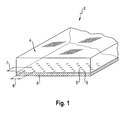
- a display 3 of an electronic device to be operated with the user interface according to the invention has a transparent, touch-sensitive surface 4. Below this surface 4, integrated into the display 3, the interaction arrangement provided according to the invention is arranged. This is formed in the example shown by an array on a support 6 arranged electrical coils 5, 5 '. As can be seen from the figure, the coils 5, 5 ', which can also be referred to as micro-coils due to their small dimensions, are arranged in a plurality of rows and columns, with an equal column spacing between the coils 5, 5' of one row and thus between the columns of the array 8th consists.
- the coils 5, 5 'of mutually adjacent rows have an offset to one another which corresponds to half the column spacing 8.
- the coils 5, 5 'of adjacent columns are arranged in a half line spacing 7 corresponding offset.
- the second essential element of the user interface is the input means 1 to be moved by a user and to be brought into contact with the touch-sensitive surface 4 of the display 3 for the purpose of inputs and / or on the surface 4
- Fig. 2 is an example of an input means 1 in interaction with the interactive means in the form of the array of coils 5, 5 'having touch-sensitive display 3 according to Fig. 1 shown.
- the input means 1 is formed in the illustrated example in the form of a stylus, of which in the present case only the tip is indicated.
- this tip of the permanent magnet 2 is arranged, whose magnetic field is brought in by the user inputs in a magnetic interaction with the interaction arrangement, that is arranged in an array of coils 5, 5 '.
- the coils 5, 5 'of the interaction arrangement are aligned so that their longitudinal axis surrounded by the turns of the coil 5, 5' is arranged orthogonal to the display plane.
- At least one of the coils 5, 5 'located in each case in the vicinity of the current position of the input means 1 brought into interaction with the interaction arrangement is flowed through by a current, under the control of a processing unit, not shown, of the electronic device equipped with the touch-sensitive display 3.
- a magnetic field is built up which interacts with the magnetic field the permanent magnet 2 of the input means 1 or the stylus occurs.
- the display 3 which approximates the perceptions when writing on paper, becomes due to the interaction of the magnetic field of the current-carrying coil or coils 5, 5 'with the magnetic field of the permanent magnet 2 when moving the stylus on the surface 4 a Increased friction resistance simulated in a sense.
- the coil or coils 5, 5 'in the vicinity of the equipped with the permanent magnet 2 stylus flows through a current whose polarity is chosen so that the permanent magnet 2 of the stylus by the magnetic field of the corresponding coil or coils 5, 5' slightly tightened becomes.
- the current flowing through a coil 5, 5 ' in contrast to the other coils 5, 5' are each shown with a solid circle circumference.
- the current position of the stylus can be determined, for example, using known technologies of capacitive displays.
- the coils 5, 5 ' which are located in the vicinity of the stylus and its permanent magnet 2, alternately switched between an operating state for determining the stylus position on the one hand and an operating state for generating the reminding of the writing on paper feedback.
- the respective coils 5, 5 ' are therefore energized in rapid change and scanned for the evaluation of the voltage induced on them.
- targeted energization of the coils 5, 5 'of the interaction arrangement for example, to guide the stylus to assist in drawing a horizontal line.
- the latter array lines form a kind of limitation, within which the input means or the stylus is "captured".
- the permanent magnet 2 in the tip of the input device 1 or stylus brought into contact with the touch-sensitive display 3 is arranged such that one of its poles (assuming the north pole) faces the touch-sensitive surface 4 of the display 3.
- another permanent magnet may be arranged at the other end of the stylus another permanent magnet, which is preferably oriented so that its south pole points in the direction of the respective end of the stylus. If the user turns the stylus so that the last-mentioned permanent magnet 2 of the stylus is brought into contact with the touch-sensitive surface 4, the polarity of the stylus induced on the touch-sensitive surface 4 in the coils 5, 5 'underneath is determined Voltage is opposite in polarity to the situation shown in the diagram. This can be evaluated by a processing unit of the user-interface operated electronic device in that with one tip of the stylus when moving along the display 3 lines are drawn, whereas these can be "erased" by turning the stylus with the other tip.
Landscapes
- Engineering & Computer Science (AREA)
- General Engineering & Computer Science (AREA)
- Theoretical Computer Science (AREA)
- Human Computer Interaction (AREA)
- Physics & Mathematics (AREA)
- General Physics & Mathematics (AREA)
- Position Input By Displaying (AREA)
Abstract
Description
Die Erfindung betrifft eine Benutzerschnittstelle für ein mit einer Verarbeitungseinheit ausgestattetes elektronisches Gerät, also insbesondere für ein computerbasiertes Endgerät. Sie bezieht sich insbesondere auf eine spezielle Ausbildung einer derartigen Benutzerschnittstelle im Hinblick auf deren Funktion als Eingabeeinrichtung zur Bedienung eines mit ihr ausgestatteten Geräts, durch welche einem Benutzer bei Eingaben in das Gerät ein gewisses haptisches Feedback vermittelt wird. Die Art des Feedbacks ist hierbei abhängig von der jeweiligen, unter mehreren Möglichkeiten auswählbaren konkreten Ausgestaltung der Benutzerschnittstelle. Sie ist ferner entsprechend dazu vorgesehener Ausbildungsformen der Erfindung auf die Art einer jeweiligen Eingabe abstimmbar. Insbesondere ist die vorgeschlagene Lösung aber darauf ausgerichtet, dem Nutzer bei handschriftlichen Eingaben in Form von Text, Zeichnungen und dergleichen ein haptisches Feedback zu vermitteln, welches an entsprechende Wahrnehmungen beim Schreiben oder Zeichnen auf Papier angenähert ist.The invention relates to a user interface for an electronic device equipped with a processing unit, that is to say in particular for a computer-based terminal. In particular, it relates to a specific embodiment of such a user interface with regard to its function as an input device for operating a device equipped with it, by means of which a certain haptic feedback is conveyed to a user during inputs to the device. The type of feedback here depends on the particular, selectable from several options concrete design of the user interface. It is further tuned in accordance with intended embodiments of the invention in the manner of a respective input. In particular, however, the proposed solution is designed to provide the user with handwritten inputs in the form of text, drawings and the like a haptic feedback, which is approximated to corresponding perceptions when writing or drawing on paper.
In jüngerer Zeit gelangen mit der zunehmenden Verbreitung von Tablet-PCs, Smartphones und ähnlichen Geräten in zunehmendem Maße berührungsempfindliche Displays (Touchscreens) zum Einsatz, welche den Benutzern entsprechender Geräte deren Bedienung und Eingaben mittels der Finger ermöglichen. Diese Art der Bedienung beziehungsweise des Tätigens von Eingaben in Endgeräten mit berührungsempfindlichen Displays ist sehr intuitiv und trifft daher auf großen Zuspruch der Benutzer. Allerdings unterliegt die Eingabe an Touchscreens unter Zuhilfenahme der Finger auch gewissen Beschränkungen. Diese werden insbesondere dann deutlich, wenn beispielsweise graphische Eingaben zur Erstellung von Skizzen oder Zeichnungen eine feinere Kontrolle der Eingabeeinrichtung beziehungsweise des Eingabemittels erfordern. Es sind daher auch Geräte entwickelt worden, welche an ebenfalls berührungsempfindlichen Displays Eingaben mittels eines Stiftes, eines so genannten Stylus, ermöglichen. Dennoch ist auch hierbei die erzielbare Genauigkeit der Eingabe für manche Anwendungsfälle eventuell zu gering, was insbesondere durch die häufig zum Schutz des Displays verhältnismäßig stumpfe Spitze entsprechender Eingabestifte bedingt ist.Recently, with the increasing use of tablet PCs, smart phones and similar devices increasingly touch-sensitive displays (touch screens) are used, which allow users of corresponding devices their operation and inputs by means of the fingers. This type of operation or the making of inputs in terminals with touch-sensitive displays is very intuitive and therefore meets with great popularity of users. However, the input to touchscreens with the help of the fingers is also subject to certain restrictions. These become particularly clear when, for example, graphic inputs for creating sketches or drawings require finer control of the input device or of the input device. Therefore, devices have also been developed which enable inputs on a touch-sensitive display by means of a stylus. Nevertheless, in this case too, the achievable accuracy of the input for some Use cases may be too low, which is due in particular to the relatively blunt for the protection of the display tip corresponding styli.
Für Anwendungen mit sehr hohen Genauigkeitsanforderungen, das heißt dem Erfordernis einer sehr feinen Kontrolle über die Eingabeeinrichtung, stellt die Verwendung von gegenüber dem Display der Endgeräte separaten Grafiktabletts eine Alternative dar. Deren Bedienung wird jedoch als weniger intuitiv empfunden als insbesondere die Fingereingabe am Display. Dies ist insbesondere darauf zurückzuführen, dass die Koordination zwischen der Eingabefläche des Grafiktabletts und dem Bildschirm zumindest für den ungeübten Nutzer verhältnismäßig schwierig ist.For applications with very high accuracy requirements, ie the requirement of a very fine control over the input device, the use of separate from the display of the terminal devices graphics tablets is an alternative. However, their operation is perceived as less intuitive than, in particular, the touch on the display. This is due in particular to the fact that the coordination between the input surface of the graphics tablet and the screen is relatively difficult, at least for the inexperienced user.
Abgesehen von den häufig stumpfen Spitzen der für eine unmittelbare Eingabe am berührungsempfindlichen Display verwendeten Eingabestifte besteht ein weiteres grundsätzliches Problem darin, dass die glatte Oberfläche des Displays beim Zeichnen oder Schreiben durch den Nutzer gegenüber der Verwendung von Stift und Papier als ungewohnt und unangenehm empfunden wird. Grund ist das Fehlen der von herkömmlichen Stiften her gewohnten Reibung auf Papier. Zudem gleitet häufig die Hand selbst nicht gut über die Glasoberfläche entsprechender Displays, was unter anderem durch die Feuchtigkeit der Hautoberfläche begründet ist. Prinzipbedingt lassen sich jedoch Bildschirmoberflächen beziehungsweise die Oberflächen berührungsempfindlicher Displays nicht aufrauen, da sich hierdurch die optischen Eigenschaften für die Wiedergabe der an ihnen auszugebenden Informationen verschlechtern würden.Apart from the often blunt tips of the styluses used for immediate input to the touch-sensitive display, another fundamental problem is that the smooth surface of the display is perceived as unfamiliar and unpleasant to the user when drawing or writing against the use of pen and paper. The reason for this is the lack of friction on paper from conventional pencils. In addition, the hand often does not glide well over the glass surface of corresponding displays, which is partly due to the moisture of the skin surface. Due to the principle, however, screen surfaces or the surfaces of touch-sensitive displays can not roughen, since this would impair the optical properties for the reproduction of the information to be output to them.
Aufgabe der Erfindung ist es, eine Benutzerschnittstelle bereitzustellen, welche Eingaben an einem elektronischen Gerät ermöglicht und dabei ihrem Benutzer beim Zeichnen oder Schreiben von Hand ein adäquates, an die Verwendung von Stift und Papier erinnerndes Feedback vermittelt. Gemäß entsprechenden Ausgestaltungen soll es die bereitzustellende Lösung auch ermöglichen, den Benutzer bei der Eingabe, in Anpassung an den jeweiligen Anwendungsfall, in unterstützender Weise haptisch zu führen.The object of the invention is to provide a user interface which allows inputs to an electronic device and thereby gives its user when drawing or writing by hand an adequate, reminding of the use of pen and paper feedback. According to corresponding embodiments, it should also enable the solution to be provided, the To guide users during input, in adaptation to the respective application, in a supportive haptic manner.
Die Aufgabe wird durch eine Benutzerschnittstelle mit den Merkmalen des Patentanspruchs 1 gelöst. Vorteilhafte Aus- beziehungsweise Weiterbildungen der Erfindung sind durch die Unteransprüche gegeben.The object is achieved by a user interface having the features of patent claim 1. Advantageous embodiments or further developments of the invention are given by the subclaims.
Die zur Lösung der Aufgabe vorgeschlagene Benutzerschnittstelle für elektronische Geräte, welche mit einer Verarbeitungseinheit ausgestattet, also mehr oder weniger computerbasiert sind, besteht aus einem eine berührungsempfindliche Oberfläche aufweisenden, zur Aus- und Eingabe dienenden Display und einem durch einen Nutzer von Hand zu bewegenden Eingabemittel. Sie ist, wie grundsätzlich aus dem Stand der Technik bekannt, so gestaltet, dass das Eingabemittel für eine Eingabe mit der berührungsempfindlichen Displayoberfläche in Kontakt zu bringen oder/und an dieser entlangzubewegen ist. Das vorgenannte Display fungiert mithin sowohl zur Ausgabe von Informationen und/oder von visuellen medialen Inhalten als auch zur Entgegennahme von einem Benutzer mithilfe des Eingabemittels gemachter Eingaben. In Hinblick auf seine Ausgabefunktion sei dabei darauf hingewiesen, dass im Zusammenhang mit der erfindungsgemäßen Benutzerschnittstelle von einem Display ausgegangen wird, welches nicht lediglich dazu dient, die durch einen Benutzer gemachten Eingaben zu visualisieren, sondern allgemein zur Ausgabe durch das mit der Benutzerschnittstelle ausgestattete elektronische Gerät bereitgestellter Informationen und Inhalte.The proposed for solving the task user interface for electronic devices, which are equipped with a processing unit, that is more or less computer-based, consists of a touch-sensitive surface having, serving for output and input display and a user to be moved by a user input means. As is well known in the art, it is designed to bring the input means into contact with and / or move along the touch-sensitive display surface. The aforesaid display thus functions both to output information and / or visual media content and to accept input from a user using the input means. With regard to its output function, it should be pointed out that in connection with the user interface according to the invention a display is assumed which serves not merely to visualize the inputs made by a user, but generally for output by the user-interface-equipped electronic device provided information and content.
Erfindungsgemäß weist das bereits mehrfach angesprochene, in seinen unterschiedlichen möglichen Ausprägungen nachfolgend noch detaillierter darzustellende Eingabemittel mindestens einen Permanentmagneten auf. Gleichzeitig ist in dem Display unterhalb der berührungsempfindlichen Oberfläche sowie parallel zu dieser eine hinsichtlich möglicher Ausbildungsformen ebenfalls noch näher zu erläuternde Interaktionsanordnung ausgebildet. Die Interaktionsanordnung, welche sich hinsichtlich ihrer Ausdehnung über den (im Wesentlichen gesamten) berührungsempfindlichen Bereich, aber eben aus der Sicht des Benutzer unterhalb der berührungsempfindlichen Oberfläche erstreckt, ist in jedem Falle so gestaltet, dass das Magnetfeld des mindestens einen Permanentmagneten des Eingabemittels während einer mittels diesem vorgenommenen Eingabe (Eingabe = In-Kontakt-Bringen des Eingabemittels mit der berührungsempfindlichen Oberfläche des Displays oder Entlangbewegen des Eingabemittels an dieser Oberfläche) in eine magnetische Wechselwirkung mit der besagten Interaktionsanordnung tritt. Die Gestaltung ist dabei derart, dass die vom Benutzer beim Entlangführen des Eingabemittels an der berührungsempfindlichen Displayoberfläche empfundene Reibung zumindest partiell erhöht ist. Die Erhöhung der empfundenen Reibung beziehungsweise des empfundenen Reibungswiderstandes bezieht sich dabei auf einen Vergleich mit den Gegebenheiten beim Entlangführen desselben Eingabemittels an einem nicht mit der erfindungsgemäß vorgesehenen Interaktionsanordnung ausgestatten, aber gegebenenfalls ansonsten im Wesentlichen in gleicher Weise ausgebildeten Display. Bei einem insoweit nur hypothetisch für den Vergleich hinsichtlich des empfundenen Reibungswiderstandes herangezogenen Display könnte es sich aber auch ohne das Vorhandensein der erfindungsgemäß vorgesehenen Interaktionsanordnung um ein berührungsempfindliches, beispielsweise nach dem Prinzip des kapazitiven Displays arbeitendes Display handeln. In diesem Zusammenhang soll daher ausdrücklich darauf hingewiesen werden, dass von der Erfindung sowohl Benutzerschnittstellen umfasst sind, bei denen die Interaktionsanordnung des als Bestandteil der Benutzerstelle ausgebildeten Displays mit bekannten Technologien zur Realisierung einer Berührungsempfindlichkeit kombiniert ist, als auch solche, bei denen die Berührungsempfindlichkeit des Displays erst durch das Vorhandensein einer (dann allerdings - wie nachfolgend noch zu erläutern - in bestimmter Weise ausgebildeten) Interaktionsanordnung gegeben ist. Entscheidend ist es insoweit, dass die Interaktionsanordnung des Display in ihrem Zusammenwirken mit dem Eingabemittel einem Benutzer der erfindungsgemäßen Benutzerschnittstelle beim Entlangbewegen des Eingabemittels an der berührungsempfindlichen Displayoberfläche ein haptisches Feedback vermittelt. Zusätzlich kann - muss aber nicht - die Interaktionsanordnung bei geeigneter Ausbildung auch zur Bestimmung der jeweiligen aktuellen Position des mit ihr in Kontakt gebrachten Eingabemittels genutzt werden.According to the invention, the input means, which has already been mentioned several times and which, in its different possible forms, will be represented in more detail below, has at least one permanent magnet. At the same time in the display below the touch-sensitive surface and parallel to this one with respect to possible embodiments also to be explained in more detail interaction arrangement is formed. The interaction arrangement, which extends in terms of its extent over the (substantially total) touch-sensitive area, but just from the perspective of the user extends below the touch-sensitive surface is designed in each case so that the magnetic field of the at least one permanent magnet of the input means during an input made by this input (input = In contacting the input means with the touch-sensitive surface of the display or moving along the input means on that surface) enters into a magnetic interaction with said interaction arrangement. The design is such that the perceived by the user when passing the input means on the touch-sensitive display surface friction is at least partially increased. The increase in the perceived friction or the perceived frictional resistance relates to a comparison with the circumstances when following the same input means on a display not equipped with the interaction arrangement provided according to the invention but possibly otherwise substantially in the same way. In the case of a display hypothetically used for the comparison with regard to the perceived frictional resistance, however, without the presence of the interaction arrangement provided according to the invention, it could also be a touch-sensitive display operating on the principle of the capacitive display, for example. In this connection, it is therefore to be expressly pointed out that the invention encompasses both user interfaces in which the interaction arrangement of the display formed as part of the user station is combined with known technologies for realizing a touch sensitivity, as well as those in which the touch sensitivity of the display only by the presence of a (then, however, as will be explained below - trained in a certain way) interaction arrangement is given. It is decisive insofar that the interaction arrangement of the display in its interaction with the input means conveys to a user of the user interface according to the invention a haptic feedback when the input means moves along the touch-sensitive display surface. In addition, but not necessarily, the interaction arrangement can be carried out in a suitable manner Training also be used to determine the respective current position of the input means brought into contact with it.
Für die Realisierung der bereits mehrfach erwähnten Interaktionsanordnung sind gemäß der Erfindung zwei grundsätzlich mögliche Ausbildungsformen vorgesehen. Entsprechend einer ersten Ausbildungsform handelt es sich dabei um eine stark vereinfachte (bezüglich des praktischen Einsatzes auch eingeschränkte) passive Lösungsvariante. Diese passive Lösungsvariante ist dadurch gegeben, dass die Interaktionsanordnung in Form einer ferromagnetischen Schicht ausgebildet ist, welche dem zur Benutzerschnittstelle gehörenden Display selbst keine Berührungsempfindlichkeit verleiht, sondern beim Entlangbewegen des Eingabemittels an der Displayoberfläche lediglich ein Feedback in Form einer Erhöhung des vom Benutzer empfundenen Reibungswiderstandes bewirkt. Dem Begriff "Schicht" liegt in diesem Zusammenhang ein weit gefasstes Verständnis zugrunde, welches über die Möglichkeit der Erzeugung einer solchen "Schicht" mittels einer Beschichtungstechnologie, wie zum Beispiel durch Aufdampfen, hinausgeht. Es handelt sich vielmehr gewissermaßen um eine parallel zu der berührungsempfindlichen Oberfläche des Displays angeordnete Ebene im Sinne einer flächenartigen, das heißt im Wesentlichen zweidimensionalen Struktur, die jedoch beispielsweise aufgrund einer entsprechenden Profilierung bezüglich ihrer großen (zur Displayoberfläche parallelen) Flächenbegrenzungen nicht vollständig plan sein muss. Eine solche Schicht kann demnach zum Beispiel durch eine entsprechende Beschichtung der Rückseite eines berührungsempfindlichen Displays oder aber durch Anordnung einer ferromagnetischen (gegebenenfalls nicht vollständig planen) Folie oder Platte innerhalb des Displays oder an dessen Rückseite realisiert werden. Auch die Möglichkeit einer mehrlagigen Ausbildung, mit insbesondere einer gezielten Strukturierung oder mit einer bezüglich des Materials lokal variabel ausgebildeten, der Displayoberfläche zugewandten Decklage, soll insoweit von dem Begriff umfasst sein. Gemäß möglicher Weiterbildungen dieser ersten grundsätzlichen Lösungsvariante, zu welchen später noch nähere Ausführungen gegeben werden sollen, kann die dabei vorgesehene ferromagnetische Schicht zur Unterstützung des Nutzers in bestimmten Eingabesituationen in geeigneter Weise strukturiert sein. Die Strukturierung kann dabei für eine gerichtete Führung des an der berührungsempfindlichen Oberfläche entlangbewegten Eingabemittels mehr oder weniger regelmäßig sein, das heißt festen Vorgaben beziehungsweise Strukturmustern folgen oder auch unregelmäßig unter Erzeugung einer leichten Inhomogenität bezüglich der Wechselwirkung mit dem Magnetfeld des Permanentmagneten des Eingabemittels gestaltet sein.For the realization of the already mentioned several times interaction arrangement two basically possible embodiments are provided according to the invention. According to a first form of training, this is a much simplified (with regard to the practical use also limited) passive solution variant. This passive solution variant is given by the fact that the interaction arrangement is designed in the form of a ferromagnetic layer which does not impart touch sensitivity to the display belonging to the user interface, but merely causes feedback in the form of an increase in the frictional resistance perceived by the user when the input means move along the display surface , The term "layer" in this context is based on a broad understanding, which goes beyond the possibility of producing such a "layer" by means of a coating technology, such as vapor deposition. Rather, it is to a certain extent a plane arranged parallel to the touch-sensitive surface of the display in the sense of a planar, ie substantially two-dimensional structure, which, however, does not have to be completely flat, for example due to a corresponding profiling with respect to its large (parallel to the display surface) surface boundaries. Accordingly, such a layer can be realized, for example, by a corresponding coating on the back of a touch-sensitive display or by arranging a ferromagnetic (possibly not completely planar) film or plate within the display or on the back thereof. Also, the possibility of a multi-layered training, with in particular a targeted structuring or with respect to the material locally variably formed, the display surface facing top layer, should be included in the extent of the term. According to possible further developments of this first basic solution variant, to which further details are to be given later, the ferromagnetic layer provided in this case can be used to assist the user in certain input situations be structured in a suitable manner. In this case, the structuring may be more or less regular for directional guidance of the input means moved along the touch-sensitive surface, that is to say follow fixed patterns or even irregularly designed to produce a slight inhomogeneity with respect to the interaction with the magnetic field of the permanent magnet of the input means.
Die zweite grundsätzliche Ausbildungsform der Erfindung besteht darin, die angesprochene Interaktionsanordnung in Form eines Arrays aus elektrischen Spulen zu realisieren. Hierbei sind die in einem Array angeordneten Spulen bezüglich der berührungsempfindlichen Displayoberfläche so angeordnet, dass eine von ihren Spulenwindungen umgebene Achse orthogonal zu der Displayoberfläche ausgebildet ist. Vorzugsweise handelt es sich bei den Spulen um kleinvolumige beziehungsweise miniaturisierte Spulen mit einem zumindest geringen Durchmesser, welche daher auch als Mikrospulen charakterisiert werden können. Die zur Vermittlung des gewünschten Feedbacks an den Benutzer erforderliche Wechselwirkung zwischen dem Eingabemittel beziehungsweise dessen Magnetfeld und der Interaktionsanordnung wird bei der durch ein Spulenarray realisierten Ausbildungsform erfindungsgemäß dadurch erreicht, dass jeweils mindestens eine der sich beim Entlangbewegen des Eingabemittels an der berührungsempfindlichen Displayoberfläche im Umfeld des Eingabemittels befindenden Spulen von einem Strom durchflossen wird.The second basic embodiment of the invention is to realize the mentioned interaction arrangement in the form of an array of electric coils. In this case, the coils arranged in an array are arranged relative to the touch-sensitive display surface in such a way that an axis surrounded by their coil turns is formed orthogonal to the display surface. Preferably, the coils are small-volume or miniaturized coils with an at least small diameter, which can therefore also be characterized as micro-coils. The interaction between the input means or its magnetic field and the interaction arrangement required for imparting the desired feedback to the user is achieved in the embodiment realized by a coil array in that at least one of the at least moving ones of the input means on the touch-sensitive display surface in the environment of the input means A current flows through it.
Für die Anordnung der elektrischen Spulen bei der zuletzt beschriebenen Ausbildungsform der Interaktionsanordnung sind grundsätzlich mehrere Möglichkeiten gegeben. In jedem Falle sind bei einem derartigen Array die elektrischen Spulen in mehreren Zeilen und Spalten unterhalb der berührungsempfindlichen Oberfläche des zu der Benutzerschnittstelle gehörenden Displays angeordnet. Sie haben zudem vorzugsweise in den einzelnen Zeilen zueinander gleiche Abstände und sind darüber hinaus auch in den Spalten mit jeweils gleichem Abstand angeordnet, wobei der letztgenannte Abstand, dem Seitenverhältnis des Displays Rechnung tragend, auch verschieden sein kann von dem Abstand der Spulen innerhalb der Zeilen. Trotz innerhalb der Zeilen und innerhalb der Spalten jeweils gleichen Abstandes der Spulen kann es dabei vorteilhaft sein, sowohl die Spulen einander benachbarter Zeilen als auch die Spulen einander benachbarter Spalten in einem Versatz anzuordnen. Die Spulen sind zwar auch hierbei innerhalb der Zeilen jeweils in einem gleichen Spaltenabstand und innerhalb der Spalten des Arrays in einem gleichen Zeilenabstand angeordnet, jedoch sind die Spulen einander benachbarter Zeilen vorzugsweise jeweils um den halben Spaltenabstand und die Spulen einander benachbarter Spalten jeweils um den halben Zeilenabstand gegeneinander versetzt angeordnet. Soweit dabei, wie ebenfalls möglich, Spaltenabstand und Zeilenabstand gleich sind, bedeutet dies, dass von einer Spule jeweils gemeinsam mit zwei Spulen einer benachbarten Zeile oder einer benachbarten Spalte die Eckpunkte eines gedachten gleichseitigen Dreiecks ausgebildet werden.For the arrangement of the electric coils in the last-described embodiment of the interaction arrangement several possibilities are given in principle. In any case, in such an array, the electrical coils are arranged in a plurality of rows and columns below the touch-sensitive surface of the display associated with the user interface. They also preferably have the same lines to each other in the same distances and are also arranged in the columns, each with the same distance, the latter distance, the aspect ratio of the display bearing, may also be different from the distance of Coils within the lines. Despite within the rows and within the columns of the same distance of the coils, it may be advantageous to arrange both the coils of adjacent rows and the coils of adjacent columns in an offset. Although the coils are also arranged within the rows in a same column spacing and within the columns of the array in a same line spacing, but the coils of adjacent rows are preferably each half the column spacing and the coils of adjacent columns each by half the line spacing arranged offset from one another. Insofar as this, as also possible, column spacing and line spacing are the same, this means that the vertices of an imaginary equilateral triangle are formed by a coil in each case together with two coils of an adjacent row or an adjacent column.
Entsprechend dem Grundprinzip der erfindungsgemäßen Benutzerschnittstelle ist, wie bereits ausgeführt, im Falle der Ausbildung der Interaktionsanordnung durch ein Array elektrischer Spulen jeweils mindestens eine der sich beim Entlangbewegen des Eingabemittels an der berührungsempfindlichen Displayoberfläche im Umfeld des Eingabemittels befindenden Spulen von einem Strom durchflossen. Vorzugsweise ist die Benutzerschnittstelle beziehungsweise deren Interaktionsanordnung jedoch so gestaltet, dass jeweils mehrere der sich im Umfeld des über die berührungsempfindliche Displayoberfläche bewegten Eingabemittels befindenden Spulen von einem Strom durchflossen werden. Während die zwischen dem Magnetfeld des Permanentmagneten des Eingabemittels und einer jeweiligen vom Strom durchflossenen Spule der Interaktionsanordnung hervorgerufene magnetische Wechselwirkung grundsätzlich dazu dient, die vom Benutzer beim Entlangführen des Eingabemittels an der Oberfläche des Display empfundene Reibung zu erhöhen und hierdurch dem Nutzer ein Feedback zu vermitteln, welches dem beim Entlangführen eines Stiftes auf Papier ähnelt, kann durch eine gezielte Bestromung einer Mehrzahl, der sich im Umfeld des Bedienelementes befindenden Spulen eine zusätzliche Führung des Eingabemittels, wie beispielsweise insbesondere eines Stylus, erreicht werden. Hierdurch ist es beispielsweise möglich, den Nutzer gezielt bei der Eingabe einer horizontalen Linie zu unterstützen. Bei der Eingabe eines Textes mithilfe des Eingabemittels kann der Nutzer zudem darin unterstützt werden, sich ohne das Vorhandensein sichtbarer Linien innerhalb einer horizontal verlaufenden Textzeile zu bewegen und dabei außerdem die Buchstaben mit einer sehr gleichmäßigen Schrift, nämlich ohne über eine gedachte Linie hinausgehende Ober- und Unterzüge, zu schreiben. Eine entsprechende Führung des Eingabemittels lässt sich auch durch eine unterschiedliche Bestromung der Spulen des Arrays erreichen, das heißt dadurch, dass die einzelnen Spulen von einem Strom mit zueinander unterschiedlicher Stromstärke und/oder Stromrichtung durchflossen werden. Durch eine Modulation der durch den jeweiligen Spulenstrom erzeugten Felder kann der Effekt einer gezielten Führung des Eingabemittels auf der Oberfläche des Displays gegebenenfalls noch zusätzlich beeinflusst werden. Durch eine hinsichtlich der Stromstärke und/oder der Stromrichtung unterschiedliche Bestromung der Spulen zu unterschiedlichen Zeitpunkten und/oder in Abhängigkeit von Position oder Bewegung des Eingabemittels auf der Displayoberfläche lässt sich das dem Nutzer vermittelte haptische Feedback aufgrund der dadurch unterschiedlichen auf das Eingabemittel wirkenden Abstoßungs - oder Anziehungskräfte auch dynamisch gestalten. So lassen sich Richtungs- und Geschwindigkeits-Änderungen des Eingabemittels berücksichtigen Zum Beispiel könnte man die "Reibung" (also die empfundene Reibung), ähnlich wie bei einer physikalischen Reibung auf Papier, proportional zu Geschwindigkeit verringern. Alternativ könnte man aber auch die Reibung erhöhen, um ein Abrutschen zu vermeiden.In accordance with the basic principle of the user interface according to the invention, as already stated, in the case of the formation of the interaction arrangement by an array of electric coils, at least one of the coils located on the touch-sensitive display surface in the vicinity of the input means as it travels along the input means is traversed by a current. Preferably, however, the user interface or its interaction arrangement is designed such that a respective current flows through a plurality of the coils located in the vicinity of the input means moving over the touch-sensitive display surface. While the magnetic interaction produced between the magnetic field of the permanent magnet of the input means and a respective current-carrying coil of the interaction assembly serves principally to increase the friction experienced by the user as the input means passes along the surface of the display, thereby providing feedback to the user, which is similar to the following when passing a pen on paper, can be achieved by a targeted energization of a plurality of coils located in the vicinity of the control element additional guidance of the input means, such as in particular a stylus. As a result, it is possible, for example, to support the user in a targeted manner when entering a horizontal line. When inputting a text by means of the input means, the user can also be assisted in moving without the presence of visible lines within a horizontally running text line and also the letters with a very uniform font, namely without over imaginary line upper and Unterzüge, to write. A corresponding guidance of the input means can also be achieved by a different energization of the coils of the array, that is, by the fact that the individual coils are traversed by a current with mutually different current intensity and / or current direction. By modulating the fields generated by the respective coil current, the effect of a targeted guidance of the input means on the surface of the display can possibly additionally be influenced. By supplying current to the coils differently at different times and / or depending on the position or movement of the input means on the display surface, the haptic feedback imparted to the user can be determined by the repulsive or differential repulsive force acting on the input means To make the attractions dynamic as well. How to take into account direction and speed changes of the input device For example, you could reduce the "friction" (ie the perceived friction), proportional to speed, similar to a physical friction on paper. Alternatively, one could also increase the friction to prevent slipping.
Für die entsprechende Ansteuerung der jeweiligen Spulen beziehungsweise deren Bestromung wird dabei eine Verarbeitungseinheit des zu bedienenden elektronischen Geräts genutzt, welche demgemäß für eine Zusammenarbeit mit der erfindungsgemäßen Benutzerschnittstelle ausgelegt und/oder programmiert ist beziehungsweise die Benutzerschnittstelle durch entsprechende Treiber unterstützt.For the corresponding control of the respective coils or their energization while a processing unit of the electronic device to be used is used, which is accordingly designed and / or programmed for cooperation with the user interface according to the invention or supports the user interface by appropriate drivers.
Durch das zuletzt beschriebene Prinzip einer gezielten Führung des Eingabemittels (insbesondere eines Stylus) durch geeignete Bestromung der Spulen der Interaktionsanordnung lassen sich unter Einbeziehung der schon vorstehend angedeuteten Möglichkeiten zusammenfassend beispielsweise folgende Anwendungen beziehungsweise Einsatzmöglichkeiten für die erfindungsgemäße Benutzerschnittstelle angeben:
- ● Führen des Eingabemittels zu Formular- beziehungsweise Eingabefeldern in Masken/Webseiten/Spreadsheets und dergleichen,
- ● Führen des Eingabemittels zu Raster-Gitterpunkten in (technischen) Zeichnungsanwendungen,
- ● Führen des Eingabemittels zu den Verknüpfungspunkten für Verbinder bei Grafikobjekten oder zu anderen Manipulationspunkten, zum Beispiel zum Vergrößern,
- ● adaptives Feedback in Abhängigkeit der Bewegungsaktion mit dem Eingabemittel, zum Beispiel indem man die Trägheit/empfundene Reibung erhöht mit zunehmender Größe (eines Objektes), Slider-Position und dergleichen,
- ● haptische Skalenticks: Bedient man mit dem Eingabemittel einen virtuellen Skalen-Regler (Schiebe-Regler oder Drehregler) so kann man die Minor- und Major-Ticks durch ein entsprechendes Feedback für den Nutzer haptisch erfahrbar machen,
- ● (schwache) Fangbereiche für die Fenster-Rahmen bzw. Bedienfelder,
- ● Fangbereiche bei Menüs beziehungsweise Menü-Einträgen,
- ● Abstoßungslinien und "Auffangbecken/bereiche" bei unterteilten Menüs beziehungsweise kaskadierten Menüs, um ein versehentliches Herausrutschen des Eingabemittels aus dem Untermenü (und gegebenenfalls nachfolgendes "Zusammenklappen" des Menüs) zu vermeiden,
- ● Schreiben auf Linien/Zeilen: Mithilfe von Abstoßungslinien und "Auffangbecken/-bereichen" ließe sich die Bedienoberfläche eines Tablett-PC, also dessen berührungsempfindliches Display gewissermaßen virtuell linieren. Hierdurch würde das Schreiben geführt, so dass die Schreibamplituden nicht zu groß würden, die horizontale Orientierung besser beibehalten und die Textzeilen blieben hiermit besser lesbar und gegebenenfalls für eine nachfolgende Schrifterkennung besser umwandelbar. Diese Führung wäre ähnlich wie in einem linierten Notizbuch, nur nicht rein optisch sondern auch (stark) haptisch vermittelt.
- ● guiding the input means to form fields in masks / web pages / spreadsheets and the like,
- ● guiding the input device to raster grid points in (technical) drawing applications,
- ● guiding the input means to the connection points for connectors in graphic objects or to other manipulation points, for example for zooming in,
- ● adaptive feedback depending on the action of movement with the input means, for example by increasing the inertia / perceived friction with increasing size (of an object), slider position and the like,
- ● Haptic scale ticks: If you use the input device to control a virtual scale (slider or knob), you can make the minor and major ticks feel tactile for the user through appropriate feedback,
- ● (weak) capture areas for the window frames or panels,
- ● Catch areas for menus or menu entries,
- ● Repulsion lines and "catch basin / areas" in subdivided menus or cascaded menus in order to prevent accidental slipping out of the input device from the submenu (and, if necessary, subsequent "folding" of the menu),
- ● Writing on lines / lines: Using rejection lines and "catch basin / areas", the user interface of a tablet PC, ie its touch-sensitive display, could virtually be lined up virtually. This would result in the writing so that the writing amplitudes would not be too large, the horizontal orientation better preserved and the Lines of text remained more readable and, where appropriate, better convertible for subsequent character recognition. This guide would be similar to a lined notebook, just not purely visual but also (strong) tactile mediated.
Eine gewisse Führung des Eingabemittels ist auch bei einer rein passiven Ausbildung der Interaktionsanordnung in Form der erstgenannten Variante mit einer ferromagnetischen Schicht möglich - wenngleich in deutlich eingeschränkter Form. So ist es möglich, eine entsprechende Interaktionsanordnung in geeigneter Weise zu strukturieren. Hierbei können beispielsweise Ausnehmungen oder Bereiche größerer Materialstärke in der ferromagnetischen Schicht ausgebildet und dadurch eine lokal unterschiedlich starke magnetische Wechselwirkung mit dem Eingabemittel erreicht werden. Unabhängig davon und insoweit nicht zwingend mit dem Ziel einer gerichteten Führung des Eingabemittels durch eine entsprechende Strukturierung der Interaktionsanordnung, können aber in der ferromagnetischen Schicht Ausnehmungen beziehungsweise Durchbrüche auch mit Blick auf eine Gewichtsreduktion und/oder Materialersparnis ausgebildet werden.A certain guidance of the input means is also possible with a purely passive design of the interaction arrangement in the form of the former variant with a ferromagnetic layer - albeit in a clearly limited form. Thus, it is possible to structure a corresponding interaction arrangement in a suitable manner. In this case, for example, recesses or areas of greater material thickness can be formed in the ferromagnetic layer, thereby achieving a locally different strong magnetic interaction with the input means. Regardless of this and not necessarily with the aim of a directed guidance of the input means by a corresponding structuring of the interaction arrangement, but recesses or breakthroughs can also be formed in view of a weight reduction and / or material savings in the ferromagnetic layer.
Durch das haptische Feedback bekommt eine zweidimensionale, auf einem berührungsempfindlichen Display visualisierte grafische Benutzeroberfläche gewissermaßen eine dritte, haptische Dimension, welche die Möglichkeiten der Wahrnehmung und der Interaktion stark erweitert. Interessant sind die letztgenannten weitergehenden Einsatzmöglichkeiten der Benutzerschnittstelle gerade deshalb, weil sie Nutzungsmöglichkeiten eröffnen, die ohne haptisches Feedback kaum oder gar nicht gegeben sind. So ist es dem Benutzer möglich, nachdem initial ein Mal die optisch richtige Position des Bedienelements auf der berührungsempfindlichen Displayoberfläche erfasst wurde, Eingaben gleichsam blind, nämlich rein aufgrund der haptischen Rückkopplung vorzunehmen. Es dabei im Grunde nicht mehr notwendig, den Blick bei der Eingabe ständig auf dem Bildschirm beziehungsweise dem Display zu lassen. Der Benutzer kann ähnlich wie mit Papier und Stift arbeiten (Schreiben beziehungsweise Skizzieren), wobei er üblicherweise auch nicht ständig auf das Blatt schaut. Auch virtuelle Regelelemente, deren physikalische Originale sich blind, rein mit den Händen, bedienen lassen, können hiermit nutzerfreundlicher und effizienter bedient werden. Interessant ist die Technik gerade auch in Kombination mit einer Sprachausgabe für die barrierefreie Nutzung von Tablett-PCs durch sehbehinderte oder gar blinde Menschen, da sich mit ihr Grafiken, Menüs, Eingabefelder und dergleichen haptisch erfahrbar machen lassen.Through haptic feedback, a two-dimensional graphical user interface visualized on a touch-sensitive display becomes, so to speak, a third haptic dimension that greatly expands the possibilities of perception and interaction. Interestingly, the last-mentioned further uses of the user interface are just because they open up opportunities that are hardly or not at all without haptic feedback. Thus, it is possible for the user, after initially once the optically correct position of the operating element was detected on the touch-sensitive display surface to make inputs as it were blind, namely purely due to the haptic feedback. It is basically no longer necessary to keep your eyes on the screen or on the screen as you type. The user can work similarly with paper and pen (writing or sketching), whereby he usually does not constantly look at the paper. Even virtual control elements, whose physical originals can be operated blind, with their hands, can be operated more user-friendly and more efficiently. The technology is also interesting in combination with a speech output for the barrier-free use of tablet PCs by visually impaired or even blind people, because they can make graphics, menus, input fields and the like feel tactile.
Bezüglich der grundsätzlichen Gestaltung der erfindungsgemäßen Benutzerschnittstelle ist es - wie ebenfalls bereits ausgeführt - nicht zwingend vorgesehen, dass diese selbst auch der Positionsbestimmung des mit dem berührungsempfindlichen Display in Kontakt gebrachten oder an ihm entlangbewegten Eingabemittels dient. Im Vordergrund steht vielmehr der Aspekt, dem Nutzer der Eingabeeinrichtung ein Feedback zu vermitteln, welches dem beim Schreiben auf Papier vergleichbar ist und ihm gegebenenfalls ein darüber hinausgehendes, bei der Eingabe unterstützendes Feedback zu geben. Demgemäß kann es vorgesehen sein, dass es sich bei dem berührungsempfindlichen Display um ein Display handelt, welches zumindest hinsichtlich der Positionsbestimmung eines darauf positionierten Stylus beziehungsweise eines damit vergleichbaren Eingabemittels in der Art eines bereits aus dem Stand der Technik bekannten, beispielsweise nach dem Prinzip der kapazitiven Eingabe arbeitenden Touchscreens, gestaltet ist. Im Hinblick auf das gewünschte Feedback ist dabei ein entsprechendes berührungsempfindliches Display im Sinne der Erfindung im Grunde lediglich durch eine entsprechende Interaktionsanordnung, nämlich durch ein Spulenarray oder durch eine ferromagnetische Schicht ergänzt. Bei der Verwendung eines Spulenarrays als Interaktionsanordnung ist es aber auch möglich, die insoweit unterhalb der Displayoberfläche angeordneten Spulen auf der Grundlage der an ihnen durch das Magnetfeld des Eingabemittels hervorgerufenen Induktionsspannung zur Positionsbestimmung beziehungsweise zur Lokalisierung und/oder Identifizierung des Eingabemittels zu nutzen. Dabei wird die Positionsbestimmung/Lokalisierung auf der Betriebssystemebene ermöglicht, wobei keine (wie sonst bisweilen bei Pads zu beobachten) Irritationen durch versehentliche Berührungen der berührungsempfindlichen Displayoberfläche mit den Fingern entstehen.With regard to the basic design of the user interface according to the invention, it is also not necessarily provided, as has already been stated, that the latter itself also serves to determine the position of the input device brought into contact with or moved along the touch-sensitive display. Rather, the focus is rather on the aspect of providing feedback to the user of the input device, which is comparable to when writing on paper and, if appropriate, giving him additional feedback that supports the input. Accordingly, it can be provided that the touch-sensitive display is a display which, at least with regard to the position determination of a stylus positioned thereon or an input means comparable therewith, is already known from the prior art, for example according to the principle of capacitive Input working touch screens, is designed. With regard to the desired feedback, a corresponding touch-sensitive display in the sense of the invention is basically merely supplemented by a corresponding interaction arrangement, namely by a coil array or by a ferromagnetic layer. When using a coil array as an interaction arrangement, however, it is also possible to use the coils arranged below the display surface on the basis of the induction voltage produced thereon by the magnetic field of the input means for position determination or for localization and / or identification of the input means. The positioning / localization on the operating system level is possible, with no (as otherwise sometimes observed with pads) irritation by accidental Touches of the touch-sensitive display surface with the fingers arise.
Gemäß einer möglichen Weiterbildung der zuvor erläuterten Ausbildungsform mit der Möglichkeit einer Positionsbestimmung des Eingabemittels mit Hilfe der Spulen werden dabei die zur Positionsbestimmung nutzbaren Spulen unter anderem zur Verringerung des Energieverbrauchs, gegebenenfalls aber auch für eine effiziente Doppelnutzung für die Erzeugung des Feedbacks einerseits und für die Positionsbestimmung des Eingabemittels andererseits, im Wechsel bestromt und zur Ermittlung der an ihnen hervorgerufenen Induktionsspannung abgetastet. Im Hinblick auf die Genauigkeit der Positionsbestimmung für das Eingabemittel und die auch dabei genutzte Wechselwirkung seines Permanentmagneten sei an dieser Stelle darauf hingewiesen, dass heute sehr starke Permanentmagnete mithilfe von seltenen Erden produziert werden können, die trotz kleiner Abmessungen sehr große Magnetfelder erzeugen. Daher ist es möglich, auch mit kostengünstigen Spulen die Feldkomponenten des Permanentmagneten beziehungsweise die durch diese in den Spulen des Interaktionsmittels erzeugte Induktionsspannung zu detektieren und lokal differenziert auszuwerten. Auch die Positionsbestimmung des Eingabemittels erfolgt dabei unter Einbeziehung einer entsprechenden die Induktionsspannungen der einzelnen Spulen auswertenden und insoweit dafür hergerichteten beziehungsweise programmtechnisch unterstützten Verarbeitungseinheit des elektronischen Geräts, wie eines Tablett-PCs oder Smartphones.According to a possible development of the previously explained embodiment with the possibility of determining the position of the input means by means of the coils, the coils which can be used for determining the position are used, inter alia, to reduce energy consumption, but possibly also for efficient dual use for the generation of feedback on the one hand and for position determination the input means on the other hand, alternately energized and sampled to determine the induction voltage caused to them. With regard to the accuracy of the position determination for the input means and the interaction of its permanent magnet used at this point it should be noted that today very strong permanent magnets can be produced using rare earths that produce very large magnetic fields despite small dimensions. It is therefore possible to detect the field components of the permanent magnet or the induction voltage generated by them in the coils of the interaction medium, and evaluate them in a differentiated manner, even with cost-effective coils. The determination of the position of the input means also takes place by including a corresponding processing unit of the electronic device, such as a tablet PC or smartphone, which evaluates the induction voltages of the individual coils and, to this extent, has been prepared or programmed.
Unterschiedliche Ausbildungsformen der Erfindung sind auch im Hinblick auf die konkrete Ausbildung des Eingabemittels vorgesehen. Entsprechend einer ersten dieser Ausbildungsformen handelt es sich bei dem Eingabemittel, wie schon mehrfach angesprochen, um einen Stylus, bei welchem im Bereich mindestens eines seiner axialen Enden ein Permanentmagnet angeordnet ist. Vorzugsweise treten die magnetischen Feldlinien des an dem axialen Ende des Stylus angeordneten Permanentmagneten im Wesentlichen parallel zur axialen Längsrichtung des Stylus aus oder ein. Das heißt, der Permanentmagnet ist innerhalb des Stylus so angeordnet, dass dessen Nordpol oder Südpol dem entsprechenden axialen Ende des Stylus zugewandt ist. Hierbei kann es entsprechend einer möglichen Weiterbildung dieser Ausbildungsform vorgesehen sein, dass der Permanentmagnet mittels eines zu diesem Zweck an dem Stylus angeordneten Bedienelements, wie einer Art Schalter oder Knopf, durch dafür an oder in dem Stylus vorgesehene mechanische Mittel zum Wechsel der Polarität seines auf das Interaktionsmittel wirkenden Magnetfelds bezüglich seiner Ausrichtung innerhalb des Stylus drehbar ist. Eine solche Ausbildungsform des Eingabemittels beziehungsweise Stylus ist insbesondere sinnvoll im Zusammenhang mit einer Ausbildung des an oder in dem berührungsempfindlichen Display angeordneten Interaktionsmittels in Form eines Arrays elektrischer Spulen. Sofern nämlich zumindest bei einem Teil dieser Spulen die an ihnen beim Eintreten einer magnetischen Wechselwirkung mit dem Magnetfeld des Permanentmagneten des Stylus hervorgerufene Induktionsspannung mittels der Verarbeitungseinheit des mit der Eingabeeinrichtung ausgestatteten elektronischen Geräts zur Bestimmung der jeweiligen Position des Eingabemittels auf der berührungsempfindlichen Oberfläche des Display ausgewertet wird, kann der Wechsel der Polarität des Permanentmagneten zum Beispiel dahingehend ausgewertet werden, dass mithilfe des über die berührungsempfindliche Oberfläche des Displays geführten Eingabemittels entweder eine Linie gezeichnet oder eine Linie gelöscht wird. Entsprechendes gilt für eine ebenfalls vorgesehene Ausbildungsform, bei welcher in dem Stylus an jedem seiner axialen Enden ein Permanentmagnet angeordnet ist, wobei die magnetischen Feldlinien des einen Permanentmagneten am betreffenden Ende des Stylus aus diesem heraustreten und die des anderen Permanentmagneten am entgegengesetzten Ende des Stylus in diesen eintreten. Auch diese Konfiguration lässt sich durch Drehen des Stylus vom Nutzer beispielsweise für das Zeichnen und das Löschen einer Linie verwenden.Different embodiments of the invention are also provided with regard to the specific design of the input means. According to a first of these embodiments, the input means, as already mentioned several times, is a stylus in which a permanent magnet is arranged in the region of at least one of its axial ends. Preferably, the magnetic field lines of the permanent magnet disposed at the axial end of the stylus exit or enter substantially parallel to the axial longitudinal direction of the stylus. That is, the permanent magnet is within the Stylus arranged so that its north pole or south pole faces the corresponding axial end of the stylus. It may be provided according to a possible development of this embodiment, that the permanent magnet means of a arranged for this purpose on the stylus control element, such as a kind of switch or button, by provided on or in the stylus mechanical means for changing the polarity of his on the Interaction agent acting magnetic field with respect to its orientation within the stylus is rotatable. Such a form of embodiment of the input means or stylus is particularly useful in connection with an embodiment of the interaction means arranged on or in the touch-sensitive display in the form of an array of electric coils. Namely, if at least in a part of these coils, the induction voltage caused to them upon the occurrence of a magnetic interaction with the magnetic field of the permanent magnet of the stylus by means of the processing unit of the input device equipped with the electronic device for determining the respective position of the input means on the touch-sensitive surface of the display is evaluated For example, the change in polarity of the permanent magnet may be evaluated by either drawing a line or erasing a line using the input means passing over the touch-sensitive surface of the display. The same applies to a likewise provided embodiment in which a permanent magnet is arranged in the stylus at each of its axial ends, wherein the magnetic field lines of a permanent magnet at the respective end of the stylus emerge from this and that of the other permanent magnet at the opposite end of the stylus in this enter. This configuration can also be used by the user to draw and delete a line, for example, by rotating the stylus.
Der Stylus kann zudem so ausgebildet sein, dass ein axiales Ende des Stylus, in dessen Bereich ein Permanentmagnet angeordnet ist, mit einer Spitze aus einem Elastomer oder aus einem Kunststoff ausgestattet ist, innerhalb welcher der Permanentmagnet angeordnet ist. Hierdurch ist der Permanentmagnet durch den beim Aufsetzen des Eingabemittels auf die berührungsempfindliche Oberfläche ausgeübten Druck innerhalb der Spitze des Stylus axial beweglich. Dies hat zur Folge, dass sich der Permanentmagnet bei auf die berührungsempfindliche Oberfläche aufgesetztem Stylus in Abhängigkeit des dabei ausgeübten Drucks mehr oder weniger stark von der berührungsempfindlichen Oberfläche entfernt. Im Ergebnis führt dies wiederum dazu, dass die in den Spulen unterhalb der berührungsempfindlichen Oberfläche aufgrund der magnetischen Wechselwirkung hervorgerufenen Induktionsspannung unterschiedlich hoch ist, so dass sich der jeweils aufgewendete Druck bestimmen lässt und mithilfe des Eingabemittels jeweils unterschiedliche Steuerungsvorgänge an dem elektronischen Gerät ausgelöst werden können.The stylus can also be designed so that an axial end of the stylus, in the region of which a permanent magnet is arranged, is provided with a tip made of an elastomer or of a plastic, within which the permanent magnet is arranged. As a result, the permanent magnet through the upon application of the input means to the touch-sensitive surface, pressure within the tip of the stylus is axially movable. As a result, with the stylus placed on the touch-sensitive surface, the permanent magnet is more or less removed from the touch-sensitive surface as a function of the pressure exerted thereon. As a result, this in turn means that the induction voltage caused in the coils below the touch-sensitive surface due to the magnetic interaction is different, so that the pressure applied in each case can be determined and different control processes can be triggered on the electronic device by means of the input means.
Entsprechend einer weiteren möglichen Ausbildungsform des Eingabemittels handelt es sich bei diesem um einen über den Finger eines Nutzers zu ziehenden Fingerling mit einem im Bereich der Fingerkuppe angeordneten Permanentmagneten. Dem Nutzer sind somit Eingaben dadurch ermöglicht, dass er mit dem vom Fingerling überzogenen Finger die berührungsempfindliche Oberfläche des Displays berührt oder sich auf dieser entlangbewegt. Bei einer damit vergleichbaren Ausbildungsform ist das Eingabemittel als ein vom Nutzer zu tragender Fingerhandschuh ausgebildet. Hierbei kann in mehreren Fingern des betreffenden Fingerhandschuhs je ein Permanentmagnet angeordnet sein. Im letztgenannten Fall sind vorzugsweise in den mit einem Permanentmagneten ausgestatteten Fingern des Handschuhs Mittel vorgesehen, durch welche die Permanentmagnete der einzelnen Finger gegeneinander magnetisch abgeschirmt sind. Zudem kann es vorgesehen sein, dass der vorzugsweise aus einem Gewebe bestehende Handschuh die Hand eines Benutzers nur teilweise umhüllt, indem zum Beispiel nur die Teile der Hand von Stoff umhüllt sind, welche beim Schreiben an der aus Kunststoff oder Glas bestehenden berührungsempfindlichen Oberfläche des Displays entlanggleiten. Denkbar ist es auch, dass die vom Display abgewandte Seite der Hand zumindest nicht ganz vom Stoff bedeckt, sondern stark perforiert ist oder/und der Stoff die proximalen Fingerglieder nicht bedeckt. Hierdurch würde ein unnötiger vom Benutzer sicherlich als unangenehm empfundener Hitzestau vermieden. Im Hinblick auf den letztgenannten Aspekt sollte darüber hinaus ein möglichst dünner Stoff für die Ausbildung des Handschuhs verwendet werden, in dessen Fingern jedoch eine gute Fixierung des oder der Permanentmagneten gewährleistet sein muss. In Betracht kämen die Verwendung von Viskose oder mikrofaserähnlicher Materialen. Letztere könnten dabei beim Gebrauch durch einen Benutzer, das heißt beim Entlanggleiten auf dem berührungsempfindlichen Display, gleichzeitig einen gewissen Reinigungseffekt für dessen Oberfläche haben.According to a further possible embodiment of the input means, this is a finger-tip to be pulled over a user's finger with a permanent magnet arranged in the region of the fingertip. The user is thus able to make inputs by touching or sliding along the touch-sensitive surface of the display with the finger covered by the finger-finger. In a comparable embodiment, the input means is designed as a finger glove to be worn by the user. In this case, a permanent magnet may be arranged in each of several fingers of the respective finger glove. In the latter case, means are preferably provided in the equipped with a permanent magnet fingers of the glove through which the permanent magnets of the individual fingers are magnetically shielded against each other. In addition, it can be provided that the glove, which is preferably made of a fabric, only partially encloses the hand of a user, for example by wrapping only the parts of the hand of material which slide along the touch-sensitive surface of the display when writing on the plastic or glass surface , It is also conceivable that the side facing away from the display of the hand at least not completely covered by the fabric, but strongly perforated and / or the fabric does not cover the proximal phalanges. This would certainly make an unnecessary user uncomfortable felt heat accumulation avoided. With regard to the last-mentioned aspect, as thin a material as possible should be used for the formation of the glove, in whose fingers, however, a good fixation of the permanent magnet or magnets must be ensured. The use of viscose or microfiber-like materials would be considered. The latter could have a certain cleaning effect on its surface during use by a user, ie when sliding along on the touch-sensitive display.
Damit kein zu starker Gleiteffekt auftritt, kann es auch sinnvoll sein den Stoff des Handschuhs an der Hauptauflagefläche, das heißt von der Handkante bis zum Handgelenk etwas grober zu perforieren (oder eine ähnliche Wirkung per Strickverfahren zu erzeugen). Neben dem Stoff liegt dann auch etwas Haut der Hand eines Benutzers auf der Oberfläche auf, allerdings gerade nur so viel, dass die Hand weder an der Glas- oder Kunststoffoberfläche klebt, noch wegrutscht. Diese Lösung hat den großen Vorteil, dass die Haut durch den teilweisen direkten Kontakt noch eine (gewohnte) sensorische Rückmeldung liefert, die bei einem nicht perforierten Handschuh verloren ginge. Unabhängig von den vorgenannten Merkmalen und der Stoffwahl für den Handschuh könnten zudem spezielle Handschuhe für Rechts- und für Linkshänder realisiert werden.In order to avoid a too strong gliding effect, it may also make sense to perforate the fabric of the glove on the main support surface, that is, slightly coarser from the edge of the hand to the wrist (or to produce a similar effect by knitting). In addition to the fabric is then also some skin of a user's hand on the surface, but just just so much that the hand sticks neither to the glass or plastic surface, still slipping away. This solution has the great advantage that the skin through the partial direct contact still provides a (usual) sensory feedback, which would be lost in a non-perforated glove. Regardless of the aforementioned features and the choice of fabric for the glove could also be realized special gloves for right and left-handed.
Nachfolgend seien zusammenfassend nochmals einige Vorteile der Erfindung und ihrer Ausprägungen beziehungsweise deren technisches Potenzial verdeutlichende Aspekte aufgeführt, welche teilweise auch schon bei der Darstellungen zu den Vorzügen unterschiedlicher Anwendungen und Einsatzmöglichkeiten für Ausbildungsformen zur gerichteten Führung des Eingabemittels auf der Displayoberfläche angesprochen wurden:
- ● Das mittels der erfindungsgemäßen Benutzerschnittstelle erreichte haptische Feedback verleiht den auf einem Display visualisierten Elementen zur Steuerung eines elektronischen Gerätes durch Benutzereingaben gewissermaßen einer dritte, nämlich haptische Dimension, welche ganz neue Möglichkeiten der effizienteren Interaktion eröffnet,
- ● die Benutzerschnittstelle ermöglicht eine haptische Rückkopplung, die dem normalen Schreibgefühl vergleichsweise nahe kommt,
- ● die Benutzerschnittstelle ermöglicht ein feineres Arbeiten mit dem Eingabemittel, beispielsweise einem Stylus, da sich durch ein erhöhtes "Anziehungs-Feedback" das Wegrutschen mit dem Eingabemittel (Stylus/Stift) vermeiden lässt,
- ● der einfache Aufbau eines mit einem Permanentmagneten ausgestatteten Stylus erlaubt niedrige Herstellungskosten und verursacht bei Verlust des Stylus keine hohen Kosten beim Benutzer, wobei zudem durch den Einsatz eines Permanentmagneten keine Batterien/Akkus notwendig sind,
- ● es ist hinsichtlich des Eingabemittels eine Unterscheidung zwischen Fingern und Stylus und damit auch eine Unterscheidung zwischen Schrifteingabe und versehentlichem Berühren oder zusätzlichen Aktionen (Multitouch mit Stylus-Unterstützung) möglich,
- ● es besteht die Möglichkeit Druckstufen zu bestimmen,
- ● im Falle einer Ausbildung des Interaktionsmittels in Form eines Spulenarrays besteht die Möglichkeit den Neigungswinkel des Eingabemittels auf der Grundlage daraus resultierender unterschiedlicher Induktionsspannungen an den Spulen zu bestimmen
- ● bei einer Ausbildung der Benutzerschnittstelle auch zur Positionsbestimmung des Eingabemittels und Verwendung eines Stylus ist eine gegenüber einer Fingerbedienung bessere Lokalisierungsgenauigkeit für den Stylus zu erwarten, was insbesondere für hochauflösende Touch-Displays interessant sein könnte,
- ● die Spulen eines in Form eines Spulenarrays ausgebildeten Interaktionsmittels müssen nicht auf der optischen Seite des berührungsempfindlichen Displays angebracht werden, so dass der Produktionsprozess einfacher beziehungsweise modularer ist und die optischen Eigenschaften des Displays sich nicht verschlechtern.
- The haptic feedback achieved by means of the user interface according to the invention gives the elements visualized on a display for the control of an electronic device by user inputs to a certain extent a third, haptic dimension, which opens up completely new possibilities of more efficient interaction,
- ● The user interface provides haptic feedback that is relatively close to the normal typing experience
- ● The user interface allows a finer working with the input means, such as a stylus, since an increased "attraction feedback" avoids slipping with the input means (stylus / pen),
- ● The simple design of a stylus equipped with a permanent magnet allows low manufacturing costs and causes no loss of the stylus at high cost for the user, in addition, by the use of a permanent magnet no batteries / rechargeable batteries are necessary,
- ● it is possible to distinguish between fingers and stylus with regard to the input device and thus also a distinction between entering and accidentally touching text or additional actions (multitouch with stylus support),
- ● it is possible to determine pressure levels
- ● in the case of forming the interaction means in the form of a coil array, it is possible to determine the inclination angle of the input means on the basis of the resulting different induction voltages on the coils
- ● with a design of the user interface also for determining the position of the input means and use of a stylus is to be expected compared to a finger operation better localization accuracy for the stylus, which could be particularly interesting for high-resolution touch displays,
- The coils of an interaction means designed in the form of a coil array do not have to be mounted on the optical side of the touch-sensitive display, so that the production process is simpler or more modular and the optical properties of the display do not deteriorate.
Aufgrund des starken Magnetfeldes des in dem Eingabemittel verwendeten Permanentmagneten beziehungsweise der Permanentmagnete ist es zwar nicht auszuschließen, dass die sonstige Displaytechnik, speziell die Elektronik, modifiziert werden muss oder Maßnahmen zur magnetischen Abschirmung einzelner Element getroffen werden müssen. Jedoch sollte sich dies mit einem vertretbaren Aufwand bewerkstelligen lassen. Beispielsweise ist es denkbar entsprechende Teile des Displays beziehungsweise des mit ihm ausgestatteten elektronischen Gerätes mittels Elementen aus Mu-Metallen (µ-Metall, englisch Mu-metal = weichmagnetisches Metall hoher Permeabilität) abzuschirmen oder gar zu kapseln.Due to the strong magnetic field of the permanent magnet used in the input means or the permanent magnets, it is not excluded that the other display technology, especially the electronics, must be modified or measures for magnetic shielding of individual element must be taken. However, this should be done with a reasonable effort. For example, it is conceivable to shield or even encapsulate corresponding parts of the display or the electronic device equipped with it by means of elements made of Mu metals (μ metal, English Mu metal = soft magnetic metal high permeability).
Mit Bezug auf die Zeichnungen soll nachfolgend nochmals auf einige Aspekte der Erfindung eingegangen werden. Hierbei zeigen
- Fig. 1:
- Eine schematische Darstellung eines Ausschnitts einer möglichen Ausbildungsform eines mit der erfindungsgemäßen Interaktionsanordnung ausgestatteten Displays,
- Fig. 2:
- Die Interaktionsanordnung gemäß
Fig. 1 unter Weglassung der transparenten, berührungsempfindlichen Oberfläche in Interaktion mit dem Eingabemittel.
- Fig. 1:
- A schematic representation of a section of a possible embodiment of a display equipped with the interaction arrangement according to the invention,
- Fig. 2:
- The interaction arrangement according to
Fig. 1 omitting the transparent, touch-sensitive surface in interaction with the input means.
In der schematischen Darstellung der
Bei dem zweiten wesentlichen Element der Benutzerschnittstelle handelt es sich um das von einem Benutzer von Hand zu bewegende und zum Zwecke von Eingaben mit der berührungsempfindlichen Oberfläche 4 des Displays 3 in Kontakt zu bringende oder/und an dieser Oberfläche 4 entlangzuführende Eingabemittel 1. In der
Um dem Benutzer des Stylus bei dessen Entlangführen an der berührungsempfindlichen Oberfläche 4 (siehe
In der zur Veranschaulichung dienenden schematischen Darstellung ist der Permanentmagnet 2 in der Spitze des mit dem berührungsempfindlichen Display 3 in Kontakt gebrachten Eingabemittels 1 beziehungsweise Stylus so angeordnet, dass einer seiner Pole (angenommen sei der Nordpol) der berührungsempfindlichen Oberfläche 4 des Displays 3 zugewandt ist. Darüber hinaus kann (hier nicht dargestellt) an dem anderen Ende des Stylus ein weiterer Permanentmagnet angeordnet sein, welcher vorzugsweise so ausgerichtet ist, dass sein Südpol in Richtung des betreffenden Endes des Stylus zeigt. Sofern der Benutzer den Stylus umdreht, so dass von ihm der letztgenannte Permanentmagnet 2 des Stylus mit der berührungsempfindlichen Oberfläche 4 in Kontakt gebracht wird, weist die Polarität der beim Entlangbewegen des Stylus an der berührungsempfindlichen Oberfläche 4 in den darunter befindlichen Spulen 5, 5' induzierten Spannung eine gegenüber der in der Darstellung gezeigten Situation umgekehrte Polarität auf. Dies kann durch eine Verarbeitungseinheit des mit der Benutzerschnittstelle betriebenen elektronischen Geräts dahingehend ausgewertet werden, dass mit der einen Spitze des Stylus beim Bewegen entlang des Displays 3 Linien gezeichnet werden, wohingegen diese durch Umdrehen des Stylus mit der anderen Spitze "ausradiert" werden können.In the illustrative schematic illustration, the
Claims (16)
Priority Applications (1)
| Application Number | Priority Date | Filing Date | Title |
|---|---|---|---|
| EP12075135.9A EP2738646A1 (en) | 2012-11-29 | 2012-11-29 | User interface for an electronic device |
Applications Claiming Priority (1)
| Application Number | Priority Date | Filing Date | Title |
|---|---|---|---|
| EP12075135.9A EP2738646A1 (en) | 2012-11-29 | 2012-11-29 | User interface for an electronic device |
Publications (1)
| Publication Number | Publication Date |
|---|---|
| EP2738646A1 true EP2738646A1 (en) | 2014-06-04 |
Family
ID=47504583
Family Applications (1)
| Application Number | Title | Priority Date | Filing Date |
|---|---|---|---|
| EP12075135.9A Withdrawn EP2738646A1 (en) | 2012-11-29 | 2012-11-29 | User interface for an electronic device |
Country Status (1)
| Country | Link |
|---|---|
| EP (1) | EP2738646A1 (en) |
Cited By (2)
| Publication number | Priority date | Publication date | Assignee | Title |
|---|---|---|---|---|
| CN105390052A (en) * | 2015-11-24 | 2016-03-09 | 国术科技(北京)有限公司 | Magnetic mineral interactive display device |
| US11036326B2 (en) | 2019-07-02 | 2021-06-15 | Microsoft Technology Licensing, Llc | Haptic interaction via magnetic force |
Citations (3)
| Publication number | Priority date | Publication date | Assignee | Title |
|---|---|---|---|---|
| US20020125977A1 (en) * | 2001-03-09 | 2002-09-12 | Vanzoest David | Alternating pole magnetic detent |
| US20030095115A1 (en) * | 2001-11-22 | 2003-05-22 | Taylor Brian | Stylus input device utilizing a permanent magnet |
| WO2007049253A2 (en) * | 2005-10-28 | 2007-05-03 | Koninklijke Philips Electronics N.V. | Display system with a haptic feedback via interaction with physical objects |
-
2012
- 2012-11-29 EP EP12075135.9A patent/EP2738646A1/en not_active Withdrawn
Patent Citations (3)
| Publication number | Priority date | Publication date | Assignee | Title |
|---|---|---|---|---|
| US20020125977A1 (en) * | 2001-03-09 | 2002-09-12 | Vanzoest David | Alternating pole magnetic detent |
| US20030095115A1 (en) * | 2001-11-22 | 2003-05-22 | Taylor Brian | Stylus input device utilizing a permanent magnet |
| WO2007049253A2 (en) * | 2005-10-28 | 2007-05-03 | Koninklijke Philips Electronics N.V. | Display system with a haptic feedback via interaction with physical objects |
Non-Patent Citations (1)
| Title |
|---|
| PANGARO G ET AL: "THE ACTUATED WORKBENCH: COMPUTER-CONTROLLED ACTUATION IN TABLETOP TANGIBLE INTERFACES", UIST 02. PROCEEDINGS OF THE 15TH. ANNUAL ACM SYMPOSIUM ON USER INTERFACE SOFTWARE AND TECHNOLOGY. PARIS, FRANCE, OCT. 27 - 30, 2002; [ACM SYMPOSIUM ON USER INTERFACE SOFTWARE AND TECHNOLOGY], NEW YORK, NY : ACM, US, vol. CONF. 15, 27 October 2002 (2002-10-27), pages 181 - 190, XP001171580, ISBN: 978-1-58113-488-9, DOI: 10.1145/571985.572011 * |
Cited By (3)
| Publication number | Priority date | Publication date | Assignee | Title |
|---|---|---|---|---|
| CN105390052A (en) * | 2015-11-24 | 2016-03-09 | 国术科技(北京)有限公司 | Magnetic mineral interactive display device |
| CN105390052B (en) * | 2015-11-24 | 2018-02-13 | 国术科技(北京)有限公司 | A kind of magnetic mineral interaction display device |
| US11036326B2 (en) | 2019-07-02 | 2021-06-15 | Microsoft Technology Licensing, Llc | Haptic interaction via magnetic force |
Similar Documents
| Publication | Publication Date | Title |
|---|---|---|
| EP3616029B1 (en) | Tactile display having a magnetically bistable axially symmetrical linear actuator having a pole contour and switching matrix, and optical-tactile seeing aid having same | |
| EP1319214B1 (en) | Touch-sensitive display with tactile feedback | |
| DE60209776T2 (en) | DISPLAY SYSTEM WITH TACTILE GUIDANCE | |
| DE69731299T2 (en) | TOUCH SCREEN | |
| EP2920656B1 (en) | Method for the secure and intentional activation of functions and/or movements of controllable industrial equipment | |
| DE202005021427U1 (en) | Electronic device with touch-sensitive input device | |
| DE4400790A1 (en) | GUI computer mouse with force feed back and position data | |
| EP2867762B1 (en) | Method for receiving an input on a touch-sensitive panel | |
| DE4201934A1 (en) | Interactive computer system e.g. mouse with hand gesture controlled operation - has 2 or 3 dimensional user surface that allows one or two hand input control of computer | |
| DE10128908A1 (en) | Control panel or operator input field, especially for control of electronic equipment by input of complex and menu-driven commands has a multiplicity of push button elements whose function, size, shape and position can be varied | |
| EP3508968A1 (en) | Human-machine interface and method for operating a human-machine interface | |
| EP2738646A1 (en) | User interface for an electronic device | |
| DE102019124114A1 (en) | Input device with touch-sensitive input surface and input part movably mounted on a base, the base being selectively magnetically fixable on the input surface and associated input method | |
| AT518250B1 (en) | touchscreen | |
| DE102004061420A1 (en) | Operating system for a vehicle | |
| EP3100143A1 (en) | Operating aid for a touch-sensitive display | |
| DE102017004105B4 (en) | Magnetically bistable axially symmetric linear actuator with pole contour, device with this and switching matrix for tactile applications | |
| EP1881398A1 (en) | Method for positioning a cursor on a touch-sensitive screen | |
| DE202011110629U1 (en) | Device for operating a touch-sensitive screen | |
| WO2006042754A1 (en) | Computer mouse | |
| EP3281098B1 (en) | Gesture-sensitive screen and computer with gesture-sensitive screen | |
| WO2021028274A1 (en) | Operating system and method for operating the operating system | |
| EP2410400B1 (en) | Medicinal display device with an input interface and method for controlling such a device | |
| DE102010018489A1 (en) | Input device for operation of e.g. capacitive touch screen, of smart phone, has skin contact region provided with U-shaped profile at finger tip receiver that forms concave inside wall for covering finger tip | |
| DE10122319A1 (en) | Device for controlling a two-dimensional cursor in the form of a pressure sensitive strip is suitable for use with mobile electronic devices as an alternative to, or in addition to, existing cursor control devices |
Legal Events
| Date | Code | Title | Description |
|---|---|---|---|
| PUAI | Public reference made under article 153(3) epc to a published international application that has entered the european phase |
Free format text: ORIGINAL CODE: 0009012 |
|
| 17P | Request for examination filed |
Effective date: 20121129 |
|
| AK | Designated contracting states |
Kind code of ref document: A1 Designated state(s): AL AT BE BG CH CY CZ DE DK EE ES FI FR GB GR HR HU IE IS IT LI LT LU LV MC MK MT NL NO PL PT RO RS SE SI SK SM TR |
|
| AX | Request for extension of the european patent |
Extension state: BA ME |
|
| STAA | Information on the status of an ep patent application or granted ep patent |
Free format text: STATUS: THE APPLICATION IS DEEMED TO BE WITHDRAWN |
|
| 18D | Application deemed to be withdrawn |
Effective date: 20141205 |