EP2737452B1 - Method for encoding an image after resizing by deleting pixels and image transmission method between a transmitter and receiver - Google Patents
Method for encoding an image after resizing by deleting pixels and image transmission method between a transmitter and receiver Download PDFInfo
- Publication number
- EP2737452B1 EP2737452B1 EP12740972.0A EP12740972A EP2737452B1 EP 2737452 B1 EP2737452 B1 EP 2737452B1 EP 12740972 A EP12740972 A EP 12740972A EP 2737452 B1 EP2737452 B1 EP 2737452B1
- Authority
- EP
- European Patent Office
- Prior art keywords
- paths
- image
- deleted
- bundles
- lines
- Prior art date
- Legal status (The legal status is an assumption and is not a legal conclusion. Google has not performed a legal analysis and makes no representation as to the accuracy of the status listed.)
- Active
Links
- 238000000034 method Methods 0.000 title claims description 40
- 230000005540 biological transmission Effects 0.000 title claims description 10
- 239000006185 dispersion Substances 0.000 claims description 22
- 230000001186 cumulative effect Effects 0.000 description 19
- 230000006870 function Effects 0.000 description 12
- 238000013459 approach Methods 0.000 description 11
- 238000007906 compression Methods 0.000 description 7
- 230000006835 compression Effects 0.000 description 7
- 238000012217 deletion Methods 0.000 description 6
- 230000037430 deletion Effects 0.000 description 6
- 230000009467 reduction Effects 0.000 description 6
- 238000012545 processing Methods 0.000 description 4
- 230000001629 suppression Effects 0.000 description 4
- 230000008901 benefit Effects 0.000 description 3
- 230000015572 biosynthetic process Effects 0.000 description 3
- 238000010790 dilution Methods 0.000 description 3
- 239000012895 dilution Substances 0.000 description 3
- 238000003786 synthesis reaction Methods 0.000 description 3
- 238000012360 testing method Methods 0.000 description 3
- 238000004364 calculation method Methods 0.000 description 2
- 230000000694 effects Effects 0.000 description 2
- 238000003780 insertion Methods 0.000 description 2
- 230000037431 insertion Effects 0.000 description 2
- 238000011946 reduction process Methods 0.000 description 2
- 230000002123 temporal effect Effects 0.000 description 2
- 230000000007 visual effect Effects 0.000 description 2
- 230000003044 adaptive effect Effects 0.000 description 1
- 230000015556 catabolic process Effects 0.000 description 1
- 230000008859 change Effects 0.000 description 1
- 238000013144 data compression Methods 0.000 description 1
- 238000006731 degradation reaction Methods 0.000 description 1
- 230000001419 dependent effect Effects 0.000 description 1
- 238000011156 evaluation Methods 0.000 description 1
- 230000010354 integration Effects 0.000 description 1
- 230000000750 progressive effect Effects 0.000 description 1
- 238000013139 quantization Methods 0.000 description 1
- 230000008707 rearrangement Effects 0.000 description 1
- 238000011084 recovery Methods 0.000 description 1
- 210000000952 spleen Anatomy 0.000 description 1
- 230000002194 synthesizing effect Effects 0.000 description 1
- 229940034880 tencon Drugs 0.000 description 1
- 230000007704 transition Effects 0.000 description 1
Images


Classifications
-
- H—ELECTRICITY
- H04—ELECTRIC COMMUNICATION TECHNIQUE
- H04N—PICTORIAL COMMUNICATION, e.g. TELEVISION
- H04N19/00—Methods or arrangements for coding, decoding, compressing or decompressing digital video signals
- H04N19/50—Methods or arrangements for coding, decoding, compressing or decompressing digital video signals using predictive coding
- H04N19/59—Methods or arrangements for coding, decoding, compressing or decompressing digital video signals using predictive coding involving spatial sub-sampling or interpolation, e.g. alteration of picture size or resolution
-
- H—ELECTRICITY
- H04—ELECTRIC COMMUNICATION TECHNIQUE
- H04N—PICTORIAL COMMUNICATION, e.g. TELEVISION
- H04N19/00—Methods or arrangements for coding, decoding, compressing or decompressing digital video signals
- H04N19/10—Methods or arrangements for coding, decoding, compressing or decompressing digital video signals using adaptive coding
- H04N19/102—Methods or arrangements for coding, decoding, compressing or decompressing digital video signals using adaptive coding characterised by the element, parameter or selection affected or controlled by the adaptive coding
- H04N19/132—Sampling, masking or truncation of coding units, e.g. adaptive resampling, frame skipping, frame interpolation or high-frequency transform coefficient masking
-
- H—ELECTRICITY
- H04—ELECTRIC COMMUNICATION TECHNIQUE
- H04N—PICTORIAL COMMUNICATION, e.g. TELEVISION
- H04N19/00—Methods or arrangements for coding, decoding, compressing or decompressing digital video signals
- H04N19/10—Methods or arrangements for coding, decoding, compressing or decompressing digital video signals using adaptive coding
- H04N19/169—Methods or arrangements for coding, decoding, compressing or decompressing digital video signals using adaptive coding characterised by the coding unit, i.e. the structural portion or semantic portion of the video signal being the object or the subject of the adaptive coding
- H04N19/17—Methods or arrangements for coding, decoding, compressing or decompressing digital video signals using adaptive coding characterised by the coding unit, i.e. the structural portion or semantic portion of the video signal being the object or the subject of the adaptive coding the unit being an image region, e.g. an object
-
- H—ELECTRICITY
- H04—ELECTRIC COMMUNICATION TECHNIQUE
- H04N—PICTORIAL COMMUNICATION, e.g. TELEVISION
- H04N19/00—Methods or arrangements for coding, decoding, compressing or decompressing digital video signals
- H04N19/10—Methods or arrangements for coding, decoding, compressing or decompressing digital video signals using adaptive coding
- H04N19/169—Methods or arrangements for coding, decoding, compressing or decompressing digital video signals using adaptive coding characterised by the coding unit, i.e. the structural portion or semantic portion of the video signal being the object or the subject of the adaptive coding
- H04N19/182—Methods or arrangements for coding, decoding, compressing or decompressing digital video signals using adaptive coding characterised by the coding unit, i.e. the structural portion or semantic portion of the video signal being the object or the subject of the adaptive coding the unit being a pixel
-
- H—ELECTRICITY
- H04—ELECTRIC COMMUNICATION TECHNIQUE
- H04N—PICTORIAL COMMUNICATION, e.g. TELEVISION
- H04N19/00—Methods or arrangements for coding, decoding, compressing or decompressing digital video signals
- H04N19/20—Methods or arrangements for coding, decoding, compressing or decompressing digital video signals using video object coding
-
- H—ELECTRICITY
- H04—ELECTRIC COMMUNICATION TECHNIQUE
- H04N—PICTORIAL COMMUNICATION, e.g. TELEVISION
- H04N19/00—Methods or arrangements for coding, decoding, compressing or decompressing digital video signals
- H04N19/90—Methods or arrangements for coding, decoding, compressing or decompressing digital video signals using coding techniques not provided for in groups H04N19/10-H04N19/85, e.g. fractals
Definitions
- an extended image is reconstructed from the decompressed reduced image by inserting path points according to an image reconstruction algorithm.
- This description contains information about the number, nature, and position of deleted paths. This description must be as inexpensive as possible in terms of bandwidth, but it must be sufficient to allow image quality to be reconstructed, and in particular to enable an intelligible interpretation of the image by the man without significant distortion of the elements of interest. the image.
- the proposed codec encodes an image into a progressive bitstream that considers content. It also encodes the position and the value of the paths. It assumes that the horizontal and vertical spatial resolution of the image is of the form 2N pixels. For the position of the paths, it encodes the absolute coordinate x of the first pixel of the first column and the difference between the first pixel of the column previous and the first pixel of the current column. They use an arithmetic encoder of (2 N + 1 -1) symbols.
- the region of interest is defined from a map of saliency as defined in the article and they stop the reduction when the image reaches a dimension of (1.5 * w0) x (1.5 * h0) Tanaka et al ( Tanaka, Y., Hasegawa, M. and Kato, S., "Image coding using concentration and dilution based on seam carving with hierarchical search", in Proc. IEEE Int. Conf. on Acoustics Speech and Signal Processing, (2010 )) propose an image coding scheme that integrates the "seam carving". They transmit an image reduced by "seam carving" with information on the position of the paths.
- the position of the paths is approximated as pillars of length N, so that the cost of a path is (log 2 (3)) / N bpp.
- the stopping criterion is based on cumulative energy: if a path has a cumulative cost greater than a certain threshold, the reduction process stops
- Tanaka 2 et al Tanaka, Y., Hasegawa, M. and Kato, S., "Image coding using concentration and dilution based on seam carving with hierarchical search", in Proc. IEEE Int. Conf. on Acoustics Speech and Signal Processing, (2010 ) improve Tanaka et al. to limit the amount of artifacts that appear during the interpolation phase based on the idea that paths must avoid textured regions and object boundaries. If the paths go through these regions or are too close to each other, artifacts appear in linear interpolation. Paths will pass through uniform regions, even though these are important regions of the image.
- Tanaka 3 et al. Tanaka, Y., Hasegawa, M. and Kato, S., "Image concentration and dilution for video coding", IIEEJ Image Electronics and Visual Computing Workshop - IEVC2010, (2010) )
- the authors apply the method of Tanaka et al. to make video reduction based on a graphcut approach of Rubinstein et al. ( Rubinstein, M., Shamir, A. and Avidan, S. "Improved seam carving for retargeting video", ACM Transactions on Graphics, (2008) )). They remove the same path for all images and allow 8-bit connectivity with the next and previous image to avoid transition artifacts between images. To calculate the path for the current image, they use all the images in the image group or GOP. To make the evaluation, they use only one quantization parameter (QP) for all the images of two test sequences.
- QP quantization parameter
- Tanaka 4 et al. Tanaka, Y., Hasegawa, M. and Kato, S., "Seam carving with spleen-dependent seam path information", in Proc. of the IEEE Int. Conf. on Acoustics Speech and Signal Processing (ICASSP), (2011) ) propose using a piecewise linear approximation to define the optimal path.
- the novelty is that pieces of paths can have different directions and lengths. In general in these works, they remove few paths to avoid synthesis problems, but enough to have a gain on compression efficiency.
- EP 2,219,153 describes a "seam carving" method comprising steps of grouping the deleted paths for the creation of images of reduced size. This document does not deal with the reconstruction of the initial image.
- the object of the invention is to propose a method allowing the transmission of a reduced image with a description of the deleted paths which is inexpensive in bandwidth, while allowing the reconstitution of an extended quality image, in particular keeping the regions of interest allowing a good interpretation by a human being, while taking into account the temporal aspect in the case of a sequence of images.
- the subject of the invention is a coding method of the aforementioned type, according to claim 1.
- the subject of the invention is also: an image transmission method between a transmitting entity and a receiving entity, according to claim 11.
- FIG. 1 there is illustrated a method of image transmission, for example video images, between a transmitting entity 10 and a receiving entity 12.
- the transmitting entity has a flow of successive initial images forming the video and ensures on each initial image, in step 30, a reduction in the size of the image by deleting paths extending between two opposite edges. of the image, these edges being vertical or horizontal.
- the image obtained is an image qualified as reduced.
- the algorithm implemented during step 30 is a "seam carving" algorithm in English or "resizing by deletion of pixels" in French, an example of which will be given later.
- the reduced image is compressed by any compression method adapted to step 32, for example by an H.264 / AVC standard coder.
- step 34 the paths deleted in the image during step 32 are modeled by implementing a step of grouping the deleted paths according to a predetermined criterion to form path bundles and by creation and coding in a step 36 of a description of the beams of the deleted paths.
- the compressed reduced image and the description of the beams of the deleted paths are transmitted at step 37 of the transmitting entity 10 to the receiving entity 12, in particular according to a constrained bit rate link.
- the receiving entity 12 After reception, the receiving entity 12 decodes and decompresses the reduced image in step 40 according to the H.264 / AVC standard and decodes the description of the beams in step 42.
- an extended image is formed, in step 44, by inserting paths in the reduced image by applying a "seam carving" algorithm while respecting the transmitted description of the beams imposing certain constraints on the inserted paths.
- Step 30 of reducing the size of each initial image is detailed on the figure 2 .
- the video is divided into a group of images (the image being composed of a group of pixels) designated by GOP of predefined length or with a length which is defined according to the number of paths that can be deleted in each image.
- step 210 a reduction by "seam carving” is performed on the image first horizontally according to an algorithm which will be described in detail with respect to the figure 3 . Paths are then removed from one side edge to the other side edge of the image.
- the result is a vertically reduced image and a list of the complete features of the deleted horizontal paths.
- step 212 The image is then rotated by 90 ° in step 212, and a new step 214 of reducing the image by "seam carving" is always done horizontally according to the algorithm of the figure 3 .
- Vertical paths, from the point of view of the image from step 210 are then deleted between the upper edge and the lower edge of the image.
- the image rotates 90 ° in the opposite direction in step 216 before being compressed and encoded in step 32 with the other reduced images of the video.
- a modeling of the deleted paths is carried out in step 218 by grouping the deleted paths into beams according to at least one predetermined criterion and creating a description of the beams.
- the modeling algorithm of step 218 corresponding to step 34 of the figure 1 will be described next to the figure 4 .
- steps 210 and 214 the paths are deleted in such a number that the reduced image can be split into 16x16 full macro blocks to optimize the image content using standard H264 / AVC compression.
- the figure 3 illustrates in greater detail the step 210 or 214 of reducing an image.
- the reduction of the image is done iteratively, one path at each iteration.
- a path is chosen and deleted. It is chosen to best preserve the semantics of the content as described in Avidan and Shamir ( Avidan, S. and Shamir, A., "Seam Carving for Content-Aware Image Resizing,” ACM Transactions Graphics, Vol. 26, no.10, (2007 )).
- a path is an optimal path of connectivity pixels 8 crossing the image from top to bottom or from left to right.
- Connectivity 8 means that depending on the path length, the next pixel can be chosen from the 8 pixels surrounding the original pixel. In practice, only three pixels can be chosen.
- the cost of a path, or the removal of a path in the image in terms of loss of content is defined by an energy function and a cumulative energy function.
- the deleted path is chosen to be the one with the lowest cost among a set of candidate paths, i.e. the lowest cumulative energy.
- the energy map is a combination of a salience map and the gradient taken for each point of the image.
- step 310 the gradient calculated on the luminance is established for each point of the image.
- the gradient is calculated for example as exposed in Avidan and Shamir.
- step 312 a saliency map is calculated. It is established for example as described in the document Rahtu, E. and Heikkila, JA, IEEE 12th International Conference on Computer Vision Workshops, ICCV Workshops, 1137-1144 (2009) )).
- the saliency card has the advantage of being multi-scale. It does not require learning, and is calculated in the color space of the image.
- step 314 a weighting function is applied to each saliency map to take into account the temporal aspect in the case of a sequence of images.
- This weighting consists of a linear combination of the current saliency map with the previous saliency map with a weighting coefficient, equal to 0.3 for example, applied to the previous saliency map.
- each value of the weighted saliency map established in step 314 is multiplied, in step 316 by the value corresponding to the gradient map established in step 310 to form the energy map.
- Such an energy map combining a saliency map and gradient amplitude is described in Anh et al.
- the energy map is established only by calculating the gradient calculated on the luminance component as proposed by Avidan and Shamir.
- the energy card is only a saliency card.
- a threshold is applied on the saliency map to distinguish important objects or regions of interest from the bottom.
- a cumulative energy map is then set in step 320 from an energy function.
- These cumulative energy functions come from the algorithms implemented in step 316 and are used to define the minimum cumulative energy path.
- the path removed at each stage is one of all possible paths with the smallest cumulative energy.
- the first step is to traverse the image from top to bottom and to calculate the cumulative energy M for all combinations of paths and for each point (i, j).
- the cumulative energy map is established using "forward energy” as described in Rubinstein et al.
- Avidan and Shamir's proposed backward energy is used as cumulative energy to find the optimal path.
- the problem with this method is that it does not take into account the consequences of deleting a path and can create artifacts.
- an absolute energy function as proposed by Frankovich and Wong ( Frankovich, M. and Wong, A. "Enhanced Seam Carving via Integration of Energy Gradient Functionals", IEEE Signal Processing Letters, (2011) )) is used as cumulative energy. It is a combination of forward energy and gradient energy.
- the "seam carving" controlled by the bitmap is applied to each image. A number paths that can be deleted on each image are thus obtained.
- the selected selection criterion is the smallest number of deletable paths defined in the previous step. This approach has two advantages: The first is that the integrity of important untouched objects is preserved. The second is that since the dimensions are fixed and multiples of 16, we do not need to insert additional pixels and the use of the standard H264 / AVC video encoder is improved.
- step 322 a criterion for selecting the number of paths to be deleted is applied.
- step 324 the selected number of paths is deleted by successive iterations for each image and the points of the deleted paths are stored.
- the description of the beams is set in step 218.
- the grouping algorithm is illustrated on the figure 4 .
- the set of stored deleted paths is seen as a set of points.
- a rearrangement of the deleted paths, so that they do not intersect, is performed in step 402.
- a new set of paths is constructed by scanning the pixels of the image along two dimensions, in order to obtain ordered paths that do not intersect.
- a grouping of the paths, using a distance criterion between two paths, is performed in step 404.
- the following rule is applied: if the distance from the previous path to the current threshold path T_Gpe, the path is inserted into the current beam. Otherwise a new beam is created with the current path as the first element.
- the beam number is initialized, the latter being set to zero.
- the current path is the first path at one end of the image.
- step 504 the distance between the current path and the next path is calculated by any suitable distance.
- the distance used is for example a distance from Minkowski. These are, for example, distances L1 or L2.
- the distance L1 or distance from Manhattan is defined as the sum of the absolute values of the differences of coordinates between the pixels of two paths for each of the lines of the image.
- the distance L2 is the Euclidean distance, that is to say the sum of the squares of the differences of coordinates between the pixels of two paths for each of the lines of the image.
- the distance is taken equal to the maximum of the absolute values of the differences of coordinates between two pixels of the same line of the two successive paths for the set of lines.
- step 506 If in step 506, the distance is less than a threshold, the next path is assigned to the current beam in step 508. Otherwise, a new beam is created in step 210 and the next path is assigned to the new beam. beam.
- the steps 504 and following are implemented as long as there remain deleted paths to be grouped, starting from the test carried out at the step 512, the step 514 consisting of replacing the current path by the following path and considering a new one. next path.
- a description of the ordered beams of deleted paths thus obtained is carried out at step 406 as described in detail later.
- intersections are key areas formed of groups of pixels that will be used for the reconstruction of the deleted lines in the extended image.
- the image is divided into zones according to the direction of the paths.
- the dispersion of a beam p on the line n is defined as the distance between the pixels of the first and last paths of the beam p on the line n, denoted Dispersion_Beam (p, n).
- one line is selected per zone and per beam.
- the grouping of the paths is carried out before the description of the beams.
- the grouping of the paths is a criterion of distance between the paths, considering the whole length of each path, and not only the distance between two paths taken along the selected lines.
- the grouping of the deleted paths and the selection of the selected lines are carried out jointly.
- the selected line is the one that contains the intersection with the beams with the largest number of deleted paths.
- the grouping of pixels or paths by selected line is done step by step by thresholding the inter-pixel distance: any pixel whose distance to the previous pixel is less than a threshold is assigned to the preceding group of pixels, otherwise the pixel is assigned to a new group.
- Each zone is scanned line by line and the selected line is chosen as the line having the widest group, that is, the largest intersection between the line and a beam having the most pixels. This choice reflects the idea that paths must avoid important objects of the image and are concentrated in key areas. Important key areas are detected.
- the zones are composed of a set of successive lines, and can be distributed in the image in several ways.
- One method is to cut the image into evenly distributed areas.
- a second method consists in defining the zones as a set of lines around equi-distributed lines in the image.
- a third method is to split the image into distributed areas taking into account, for example, the nature of the image and its content.
- the grouping of the paths, as well as the description of the beams, that is to say the description of the groupings made along the selected lines, are carried out simultaneously.
- a compression of the groups of paths is also performed during step 406.
- step 42 After receiving and decompressing the reduced image in step 40 and decoding the description of the beams, in step 42, step 44 of synthesizing paths in the reduced image to produce the extended image is implemented. artwork.
- the energy map of the reduced image being processed is modified according to the description of the beams in order to force the inserted paths to pass through the key zones defined in the preceding phase. This approach prevents paths from passing through important objects and allows important objects to return to their original position.
- the reduced image is decompressed to obtain an uncompressed image 600.
- a description of the beams 601 is obtained by decompressing the received data.
- An energy map is calculated for the reduced image decompressed in step 602.
- the same mode of calculation of the energy map as that used for the deletion of the paths is implemented.
- it is a combination of salience maps and the gradient map.
- a test is performed in step 604 to determine if the current size of the image being processed is smaller than the original size of the image. If this is the case, the previously generated energy map is weighted to modify the energy value on the selected lines obtained from the description of the beams 601. This weighting consists of adding a maximum value on all the pixels of each selected line. except at the pixel of the desired key zone of passage for the future line inserted. The maximum value added is chosen greater than all the values of the image.
- step 608 is directly applied. This step 608 consists in determining the path to be inserted. This path is determined as the path that minimizes cumulative energy among a set of candidate paths as known per se in a seam carving method.
- step 610 it is determined whether the values of the pixels of the inserted path must be immediately indicated or not. If this is the case, these values are determined, in step 612, by a propagation method known per se, that is to say by the resumption of the values associated with one of the immediately adjacent pixels, or by an interpolation method from the values of the adjacent pixels.
- step 614 it is determined whether the size of the image being processed corresponds to the target dimension for the image. If this is not the case, a new energy map for the image being reconstituted is determined in step 616, by the same calculation method as that implemented in step 602, and the steps 604 and following are again implemented.
- step 618 If the size of the image corresponds to the target dimension, it is determined in step 618 whether values for each pixel have been assigned to the paths inserted in step 612.
- step 620 assigning values to the inserted pixels is implemented.
- This global assignment of values is performed by any suitable known methods, in particular an "inpainting" method, a texture synthesis from the recovery of a texture taken from the image, or an interpolation method.
- the reduced digital image is thus decoded at the end of this algorithm to obtain a reconstituted image.
Landscapes
- Engineering & Computer Science (AREA)
- Multimedia (AREA)
- Signal Processing (AREA)
- Compression Or Coding Systems Of Tv Signals (AREA)
Description
La présente invention concerne un procédé de codage d'une image numérique ou d'une séquence d'images numériques comportant une étape de :
- a. suppression de chemins entre deux bords opposés d'une image par un algorithme de redimensionnement par suppression de pixels pour définir une image réduite ;
- b. modélisation des chemins supprimés pour transmission avec l'image réduite en vue de l'interpolation d'une image étendue.
- at. removing paths between two opposite edges of an image by a pixel-delimiting resizing algorithm to define a reduced image;
- b. modeling deleted paths for transmission with the reduced image for interpolation of an extended image.
Pour la transmission avec un très bas débit d'images fixes ou d'une succession d'images dans le cadre de la vidéo, il est connu de mettre en oeuvre, coté entité émettrice, une méthode de redimensionnement de chaque image avant compression par suppression de certains éléments d'image. En particulier, les éléments supprimés appelés « seam » en anglais sont des chemins de points adjacents s'étendant d'un bord à l'autre de chaque image. L'image compressée et transmise est ainsi une image réduite.For the transmission with a very low bit rate of still images or a succession of images in the context of the video, it is known to implement, on the issuing entity side, a method of resizing each image before compression by deletion. certain image elements. In particular, the deleted elements called "seam" in English are paths of adjacent points extending from one edge to the other of each image. The compressed and transmitted image is thus a reduced image.
Coté entité réceptrice, une image étendue est reconstituée à partir de l'image réduite décompressée en insérant des chemins de points suivant un algorithme de reconstitution de l'image.On the receiving entity side, an extended image is reconstructed from the decompressed reduced image by inserting path points according to an image reconstruction algorithm.
Cette technique est connue sous le nom anglais de « seam carving » ou « redimensionnement par suppression de pixels» en français.This technique is known by the English name of "seam carving" or "resizing by deletion of pixels" in French.
Pour permettre une reconstitution convenable de l'image étendue à partir de l'image réduite, il est nécessaire de transmettre une description des chemins supprimés. Cette description contient des informations sur le nombre, la nature et la position des chemins supprimés. Cette description doit être aussi peu couteuse en bande passante que possible mais elle doit être suffisante pour permettre une reconstitution de qualité de l'image et notamment permettre une interprétation intelligible de l'image par l'homme sans déformation importante des éléments d'intérêt de l'image.To allow proper reconstruction of the extended image from the reduced image, it is necessary to transmit a description of the deleted paths. This description contains information about the number, nature, and position of deleted paths. This description must be as inexpensive as possible in terms of bandwidth, but it must be sufficient to allow image quality to be reconstructed, and in particular to enable an intelligible interpretation of the image by the man without significant distortion of the elements of interest. the image.
Anh et al (
Plus précisément, le codec proposé encode une image dans un « bitstream » progressif et qui tient compte du contenu. Il encode aussi la position et la valeur des chemins. Il suppose que la résolution spatiale horizontale et verticale de l'image est de la forme 2N pixels. Pour la position des chemins, il encode la coordonnée absolue x du premier pixel de la première colonne et la différence entre le premier pixel de la colonne précédente et le premier pixel de la colonne courante. Ils utilisent un codeur arithmétique de (2N+1-1) symboles.Specifically, the proposed codec encodes an image into a progressive bitstream that considers content. It also encodes the position and the value of the paths. It assumes that the horizontal and vertical spatial resolution of the image is of the form 2N pixels. For the position of the paths, it encodes the absolute coordinate x of the first pixel of the first column and the difference between the first pixel of the column previous and the first pixel of the current column. They use an arithmetic encoder of (2 N + 1 -1) symbols.
Pour les autres points, il encode la différence du pixel courant avec le pixel précédent du même chemin avec un codeur arithmétique de 3 symboles. Pour la couleur, il utilise le même concept en remplaçant la coordonnée absolue x par la valeur de R, G, B. Pour tous ces points, il a besoin d'un codeur arithmétique de 29-1 symboles. Cette représentation permet de décoder l'image à n'importe quelle résolution. Pour calculer le « seam carving », les auteurs utilisent une fonction d'énergie basée sur une carte de saillance multipliée par un gradient sur la luminance. Pour encoder la position des chemins, ils utilisent donc un codeur arithmétique adaptatif et pour encoder la valeur des chemins, ils font de la quantification avec un dictionnaire prédéfini. Pour contrôler le processus de réduction, ils définissent la boîte rectangulaire englobant la région d'intérêt de dimensions w0 x h0. La région d'intérêt est définie à partir d'une carte de saillance telle définie dans l'article et ils arrêtent la réduction lorsque l'image atteint une dimension de (1.5*w0) x (1.5*h0) Tanaka et al (
Wang et al. (
Tanaka 2 et al (
Dans Tanaka 3 et al. (
Tanaka 4 et al. (
De manière générale, l'approche traditionnelle pour reconstituer une image par « seam carving » ou « redimensionnement par suppression de pixels» est d'appliquer le même algorithme que pour la réduction mais au lieu de supprimer les chemins, ceux-ci sont insérés.In general, the traditional approach to reconstruct an image by "seam carving" or "resize by deletion of pixels" is to apply the same algorithm as for the reduction but instead of deleting the paths, these are inserted.
Le principal problème est qu'il n'y a pas de moyen pour assurer que les chemins réinsérés soient à la même position que les chemins supprimés. A l'opposé, le coût d'encodage pour transmettre chaque chemin est réellement trop important en comparaison au gain provenant de la réduction de la taille de l'image. C'est pour cela que les travaux décrits ci-dessus ont été réalisés.The main problem is that there is no way to ensure that the reinserted paths are in the same position as the deleted paths. In contrast, the cost of encoding to transmit each path is actually too great compared to the gain from reducing the size of the image. That is why the work described above has been done.
En conséquence, les approches de redimensionnement connues sans dégradation des régions d'intérêts conduisent à :
Soit un surcout d'encodage.As a result, the known resizing approaches without degradation of the regions of interest lead to:
Or an extra encoding.
Soit la perte d'information de positionnement relatif des objets d'intérêts.
Soit un redimensionnement faibleThis is the loss of relative positioning information of the objects of interest.
Either a low resize
L'invention a pour but de proposer une méthode permettant la transmission d'une image réduite avec une description des chemins supprimés qui soit peu couteuse en bande passante, tout en permettant la reconstitution d'une image étendue de qualité conservant notamment les régions d'intérêt permettant une bonne interprétation par un être humain, tout en prenant en compte l'aspect temporel dans le cas d'une séquence d'images. A cet effet, l'invention a pour objet un procédé de codage de type précité, selon la revendication 1.The object of the invention is to propose a method allowing the transmission of a reduced image with a description of the deleted paths which is inexpensive in bandwidth, while allowing the reconstitution of an extended quality image, in particular keeping the regions of interest allowing a good interpretation by a human being, while taking into account the temporal aspect in the case of a sequence of images. For this purpose, the subject of the invention is a coding method of the aforementioned type, according to claim 1.
Suivant des modes particuliers de réalisation, le procédé comporte l'une ou plusieurs des caractéristiques suivantes :
- ladite description des faisceaux comporte, pour seulement certaines lignes sélectionnées de l'image, une information sur la répartition des chemins supprimés ;
- l'information sur la répartition des chemins supprimés comporte la position de passage des chemins supprimés sur les lignes sélectionnées ;
- les lignes sélectionnées sont prises au moins chacune dans des zones équi-réparties de l'image selon la direction des chemins supprimés ;
- les lignes sélectionnées sont prises au moins chacune dans des zones réparties définies dans l'image en fonction du contenu de l'image ;
- pour une zone donnée comportant plusieurs lignes successives, une ligne sélectionnée est choisie pour chaque faisceau comme étant celle pour laquelle le faisceau présente la dispersion minimale ;
- pour une zone donnée comportant plusieurs lignes successives, une même ligne sélectionnée est choisie pour tous les faisceaux comme étant celle pour laquelle la somme des dispersions des faisceaux est minimale ;
- pour une zone donnée comportant plusieurs lignes successives, une même ligne sélectionnée est choisie pour tous les chemins comme étant celle comportant le plus grand nombre de chemins séparés les uns des autres de proche en proche d'une distance inférieure à un seuil prédéfini ;
- la création d'une description des faisceaux de chemins supprimés consiste en la définition de l'une des descriptions suivantes :
- la position de tous les chemins de chaque faisceau pour chaque ligne sélectionnée,
- la position du premier et du dernier chemins de chaque faisceau pour chaque ligne sélectionnée, ainsi que le nombre de chemins du faisceau,
- la position moyenne de chaque faisceau, correspondant à la moyenne des positions des chemins constituant le faisceau sur chaque ligne sélectionnée, ainsi que le nombre de chemins du faisceau, ou
- la position du premier chemin de chaque faisceau pour chaque ligne sélectionnée ainsi que le nombre de chemins de chaque faisceau pour chaque ligne sélectionnée ;
- ledit critère prédéterminé pour le regroupement des chemins supprimés en faisceaux de chemins est l'existence d'une distance entre les chemins adjacents d'un même groupe inférieure à une valeur seuil prédéterminée ;
- le procédé est appliqué à une séquence d'images successives et l'algorithme de redimensionnement par suppression de pixels comporte, pour la détermination des chemins à supprimer, la prise en compte d'une carte d'énergie formée d'une combinaison linéaire de la carte d'énergie de l'image courante avec la carte d'énergie de l'image précédente avec un coefficient de pondération appliqué à la carte d'énergie de l'image précédente.
- said description of the beams includes, for only certain selected lines of the image, information on the distribution of the deleted paths;
- information on the distribution of the deleted paths includes the position of passage of the deleted paths on the selected lines;
- the selected lines are taken at least each in equi-distributed areas of the image according to the direction of the deleted paths;
- the selected lines are taken at least each in distributed areas defined in the image according to the content of the image;
- for a given zone comprising several successive lines, a selected line is chosen for each beam as being that for which the beam has the minimum dispersion;
- for a given zone comprising several successive lines, the same selected line is chosen for all the beams as being that for which the sum of the dispersions of the beams is minimal;
- for a given zone comprising several successive lines, the same selected line is chosen for all the paths as being the one comprising the largest number of paths separated from each other by a distance closer to a predefined threshold;
- Creating a description of deleted path bundles consists of defining one of the following descriptions:
- the position of all the paths of each beam for each selected line,
- the position of the first and the last paths of each beam for each selected line, as well as the number of paths of the beam,
- the average position of each beam, corresponding to the average of the positions of the paths constituting the beam on each selected line, as well as the number of paths of the beam, or
- the position of the first path of each beam for each selected line and the number of paths of each beam for each selected line;
- said predetermined criterion for grouping paths removed in path bundles is the existence of a distance between adjacent paths of the same group less than a predetermined threshold value;
- the method is applied to a sequence of successive images and the pixel-delimitation algorithm comprises, for the determination of the paths to be deleted, taking into account an energy map formed of a linear combination of the energy map of the current image with the energy map of the previous image with a weighting coefficient applied to the energy map of the previous image.
L'invention a également pour objet :
un procédé de transmission d'image entre une entité émettrice et une entité réceptrice, selon la revendication 11.The subject of the invention is also:
an image transmission method between a transmitting entity and a receiving entity, according to claim 11.
L'invention sera mieux comprise à la lecture de la description qui va suivre, donnée uniquement à titre d'exemple et faite en se référant aux dessins, sur lesquels :
- la
figure 1 est une vue d'ensemble du procédé de transmission ; - la
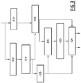
figure 2 est un organigramme général de l'algorithme mis en oeuvre par l'entité émettrice ; - la
figure 3 est un organigramme détaillé d'une étape de suppression des lignes de l'algorithme illustré sur lafigure 2 ; - la
figure 4 est un organigramme de la modélisation des lignes supprimées sous forme de faisceaux de chemins supprimés ; - la
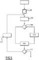
figure 5 est un organigramme du regroupement des chemins supprimés ; - la
figure 6 est organigramme détaillé de l'étape d'insertion des lignes supprimées mis en oeuvre par l'entité réceptrice ; - la
figure 7 est un exemple d'image réduite ; - la
figure 8 est la carte d'énergie de l'image réduite de lafigure 7 ; - la
figure 9 est la carte d'énergie cumulative modifiée de l'image de lafigure 8 pour tenir compte de la description des faisceaux.
- the
figure 1 is an overview of the transmission process; - the
figure 2 is a general flowchart of the algorithm implemented by the issuing entity; - the
figure 3 is a detailed flowchart of a step of deleting the lines of the algorithm shown on thefigure 2 ; - the
figure 4 is a flowchart for modeling deleted lines as deleted path bundles; - the
figure 5 is a flowchart of the grouping of deleted paths; - the
figure 6 is a detailed flowchart of the insertion step of the deleted lines implemented by the receiving entity; - the
figure 7 is an example of a reduced image; - the
figure 8 is the energy map of the reduced image of thefigure 7 ; - the
figure 9 is the modified cumulative energy map of the image of thefigure 8 to take into account the description of the beams.
Sur la
L'entité émettrice dispose d'un flux d'images initiales successives formant la vidéo et assure sur chaque image initiale, à l'étape 30, une réduction de la taille de l'image par suppression de chemins s'étendant entre deux bords opposés de l'image, ces bords étant verticaux ou horizontaux. L'image obtenue est une image qualifiée de réduite. L'algorithme mis en oeuvre, lors de l'étape 30, est un algorithme de « seam carving » en anglais ou « redimensionnement par suppression de pixels » en français dont un exemple sera donné dans la suite.The transmitting entity has a flow of successive initial images forming the video and ensures on each initial image, in
A l'issue de cette étape 30, l'image réduite est compressée par toute méthode de compression adaptée à l'étape 32 par exemple par un codeur au standard H.264/AVC.At the end of this
A l'étape 34, les chemins supprimés dans l'image lors de l'étape 32 sont modélisés par mise en oeuvre d'une étape 35 de regroupement des chemins supprimés en fonction d'un critère prédéterminé pour former des faisceaux de chemins et par création et codage lors d'une étape 36 d'une description des faisceaux des chemins supprimés.In
L'image réduite compressée et la description des faisceaux des chemins supprimés sont transmises à l'étape 37 de l'entité émettrice 10 à l'entité réceptrice 12 notamment suivant une liaison à débit contraint.The compressed reduced image and the description of the beams of the deleted paths are transmitted at
Après réception, l'entité réceptrice 12 assure le décodage et la décompression de l'image réduite à l'étape 40 selon le standard H.264/AVC et le décodage de la description des faisceaux à l'étape 42.After reception, the receiving
Enfin, une image étendue est formée, à l'étape 44, en insérant des chemins dans l'image réduite par application d'un algorithme de « seam carving » en respectant la description transmise des faisceaux imposant certaines contraintes sur les chemins insérés.Finally, an extended image is formed, in
L'étape 30 de réduction de la taille de chaque image initiale est détaillée sur la
Préalablement, la vidéo est découpée en groupe d'images (l'image étant composée d'un groupe de pixels) désigné par GOP de longueur prédéfinie ou avec une longueur qui est définie en fonction du nombre de chemins pouvant être supprimés dans chaque image.Previously, the video is divided into a group of images (the image being composed of a group of pixels) designated by GOP of predefined length or with a length which is defined according to the number of paths that can be deleted in each image.
A l'étape 210, une réduction par « seam carving » est effectuée sur l'image d'abord horizontalement selon un algorithme qui sera décrit en détail en regard de la
Il en résulte une image réduite verticalement et une liste des caractéristiques complètes des chemins horizontaux supprimés.The result is a vertically reduced image and a list of the complete features of the deleted horizontal paths.
L'image est ensuite tournée de 90°, à l'étape 212, et une nouvelle étape 214 de réduction de l'image par « seam carving » est effectuée toujours horizontalement selon l'algorithme de la
Il en résulte une image réduite horizontalement et verticalement et une liste des caractéristiques complètes des chemins verticaux supprimés.This results in a horizontally and vertically reduced image and a list of complete features of the deleted vertical paths.
L'image subit une rotation de 90° en sens inverse à l'étape 216 avant d'être compressée et encodée à l'étape 32 avec les autres images réduite de la vidéo.The image rotates 90 ° in the opposite direction in
A partir des caractéristiques de chemins horizontaux et verticaux supprimés, une modélisation des chemins supprimés est effectuée à l'étape 218 par regroupement des chemins supprimés en faisceaux suivant au moins un critère prédéterminé et création d'une description des faisceaux. L'algorithme de modélisation de l'étape 218 correspondant à l'étape 34 de la
Lors des étapes 210 et 214, les chemins sont supprimés en un nombre tel que l'image réduite puisse être découpée en macro blocs complets de dimension 16x16 pour optimiser le contenu de l'image en utilisant une compression au standard H264/AVC.In
La
La réduction de l'image s'effectue de manière itérative, à raison d'un chemin à chaque itération.The reduction of the image is done iteratively, one path at each iteration.
A chaque itération, un chemin est choisi et supprimé. Il est choisi pour préserver au mieux la sémantique du contenu comme décrit dans Avidan et Shamir (
Un chemin est un chemin optimal de pixels de connexité 8 traversant l'image de haut en bas ou de gauche à droite. La connexité 8 signifie que suivant la longueur du chemin, le pixel suivant peut être choisi parmi les 8 pixels entourant le pixel d'origine. En pratique, seuls trois pixels peuvent être choisis.A path is an optimal path of connectivity pixels 8 crossing the image from top to bottom or from left to right. Connectivity 8 means that depending on the path length, the next pixel can be chosen from the 8 pixels surrounding the original pixel. In practice, only three pixels can be chosen.
De la même manière que la suppression d'une ligne ou d'une colonne de l'image, la suppression d'un chemin de l'image n'a seulement qu'un effet local.In the same way as deleting a line or column from the image, deleting a path from the image only has a local effect.
Le coût d'un chemin, ou la suppression d'un chemin dans l'image en terme de perte de contenu est défini par une fonction d'énergie et une fonction d'énergie cumulative. Le chemin supprimé est choisi comme étant celui qui présente le coût le plus faible parmi un ensemble de chemin candidats, c'est-à-dire l'énergie cumulative la plus faible.The cost of a path, or the removal of a path in the image in terms of loss of content is defined by an energy function and a cumulative energy function. The deleted path is chosen to be the one with the lowest cost among a set of candidate paths, i.e. the lowest cumulative energy.
La plupart des travaux se sont orientés vers ces deux fonctions afin d'améliorer le choix des chemins. Ainsi le contenu important de l'image est préservé.Most of the work has been directed towards these two functions in order to improve the choice of paths. Thus the important content of the image is preserved.
Une carte d'énergie et une carte d'énergie cumulative sont ainsi crées pour chaque image.An energy map and a cumulative energy map are thus created for each image.
Dans le mode de réalisation préféré, la carte d'énergie est une combinaison d'une carte de saillance et du gradient pris pour chaque point de l'image.In the preferred embodiment, the energy map is a combination of a salience map and the gradient taken for each point of the image.
A l'étape 310, le gradient calculé sur la luminance est établi pour chaque point de l'image. Le gradient est calculé par exemple comme exposé dans Avidan et Shamir.In
A l'étape 312, une carte de saillance est calculée. Elle est établie par exemple comme décrit dans le document
La carte de saillance a l'avantage d'être multi-échelles. Elle ne nécessite pas d'apprentissage, et est calculée dans l'espace des couleurs de l'image.The saliency card has the advantage of being multi-scale. It does not require learning, and is calculated in the color space of the image.
A l'étape 314, une fonction de pondération est appliquée à chaque carte de saillance pour prendre en compte l'aspect temporel dans le cas d'une séquence d'images.In
Cette pondération consiste en une combinaison linéaire de la carte de saillance courante avec la carte de saillance précédente avec un coefficient de pondération, égal à 0,3 par exemple, appliqué à la carte de saillance précédente.This weighting consists of a linear combination of the current saliency map with the previous saliency map with a weighting coefficient, equal to 0.3 for example, applied to the previous saliency map.
Pour limiter les effets de blocs liés à l'approche multi-échelles tout en préservant les parties importantes de l'image, chaque valeur de la carte de saillance pondérée établi à l'étape 314 est multipliée, à l'étape 316 par la valeur correspondante de la carte de gradient établie à l'étape 310 pour former la carte d'énergie. Une telle carte d'énergie combinant une carte de saillance et de l'amplitude du gradient est décrite dans Anh et al.To limit the effects of blocks related to the multi-scale approach while preserving the important parts of the image, each value of the weighted saliency map established in
En variante, la carte d'énergie est établie seulement par le calcul du gradient calculé sur la composante luminance comme proposé par Avidan et Shamir.Alternatively, the energy map is established only by calculating the gradient calculated on the luminance component as proposed by Avidan and Shamir.
En variante, la carte d'énergie est seulement une carte de saillance.Alternatively, the energy card is only a saliency card.
Suivant encore d'autres variantes, d'autres cartes de saillance avec ou sans prise en compte de l'aspect temporel sont utilisées. De telles cartes sont décrites par exemple dans :
-
Hwang, D.-S. and Chien, S.-Y., "Content-aware image resizing using perceptual seam carving with human attention model", IEEE International Conférence on Multimedia and Expo,(2008 -
Chen, D.-Y. and Luo, Y.-S., "Content-Aware Video Seam Carving Based on Bag of Visual Cubes", Sixth International Conférence on Intelligent Information Hiding and Multimedia Signal Processing (IIH-MSP), (2010 -
Chiang, C.-K, Wang, S.-F, Chen, Y.-L. and Lai, S.-H,. "Fast JND-Based Video Carving With GPU Acceleration for Real-Time Video Retargeting", IEEE Transactions on Circuits and Systems for Video Technology, (2009 -
Achanta, R. and Susstrunk, S. "Saliency détection for content-aware image resizing", 16th IEEE International Conférence on Image Processing (ICIP), (2009 - En variante la carte d'énergie utilise un autre critère permettant la prise en compte des régions d'intérêt.
-
Hwang, D.-S. and Dog, S.-Y., "Content-aware image resizing using perceptual seam carving with human attention model", IEEE International Conference on Multimedia and Expo, (2008) -
Chen, D.-Y. and Luo, Y.-S., "Content-Aware Video Seam Carving Based on Bag of Visual Cubes", Sixth International Conference on Intelligent Information Hiding and Multimedia Signal Processing (IIH-MSP), (2010) -
Chiang, C.-K, Wang, S.-F, Chen, Y.-L. and Lai, S.-H ,. "Fast JND-Based Video Carving With GPU Acceleration for Real-Time Video Retargeting", IEEE Transactions on Circuits and Systems for Video Technology, (2009) -
Achanta, R. and Susstrunk, S. "Saliency detection for content-aware image resizing", 16th IEEE International Conference on Image Processing (ICIP), (2009) - As a variant, the energy card uses another criterion allowing the regions of interest to be taken into account.
A l'étape 318, afin de contrôler la quantité de chemins pouvant être supprimés, un seuil est appliqué sur la carte de saillance pour distinguer du fond les objets importants ou régions d'intérêt.In
Une carte d'énergie cumulative est ensuite établie à l'étape 320 à partir d'une fonction d'énergie. Ces fonctions d'énergies cumulatives proviennent des algorithmes mis en oeuvre à l'étape 316 et sont utilisées pour définir le chemin d'énergie cumulative minimale.A cumulative energy map is then set in
Le chemin supprimé à chaque stade est celui parmi tous les chemins possibles ayant l'énergie cumulative la plus petite.The path removed at each stage is one of all possible paths with the smallest cumulative energy.
Dans le cas du chemin vertical, la première étape est de traverser l'image de haut en bas et de calculer l'énergie cumulative M pour toutes les combinaisons de chemins et pour chaque point (i,j).In the case of the vertical path, the first step is to traverse the image from top to bottom and to calculate the cumulative energy M for all combinations of paths and for each point (i, j).
Avantageusement, la carte d'énergie cumulative est établie en utilisant la « forward Energy » comme décrit dans Rubinstein et al.Advantageously, the cumulative energy map is established using "forward energy" as described in Rubinstein et al.
L'avantage de cette fonction est qu'elle mesure la quantité d'énergie insérée due aux nouvelles frontières. Ces nouvelles frontières précédemment non adjacentes le deviennent lorsque l'on supprime un point du chemin.The advantage of this function is that it measures the amount of energy inserted due to new boundaries. These new, previously non-adjacent borders become so when you remove a point from the path.
En variante, la « backward energy » proposée par Avidan et Shamir est utilisée en tant qu'énergie cumulative pour trouver le chemin optimal. Le problème avec cette méthode est qu'elle ne prend pas en compte les conséquences de la suppression d'un chemin et peut créer des artéfacts.Alternatively, Avidan and Shamir's proposed backward energy is used as cumulative energy to find the optimal path. The problem with this method is that it does not take into account the consequences of deleting a path and can create artifacts.
Encore suivant une variante, une fonction d'énergie absolue comme proposée par Frankovich et Wong (
Dans Tanaka et al., Tanaka 2 et al., Tanaka 3 et al., l'énergie cumulative pour déterminer les chemins est modifiée en combinant la « forward energy » avec le coût d'encodage des chemins. Une telle démarche est mise en oeuvre également avantageusement dans l'invention pour le calcul des chemins.In Tanaka et al., Tanaka 2 et al., Tanaka 3 et al., Cumulative energy for determining paths is modified by combining the "forward energy" with the cost of encoding paths. Such an approach is also advantageously implemented in the invention for calculating paths.
Pour garder constantes et multiples de 16 les dimensions spatiales de l'image, le « seam carving » contrôlé par la carte binaire est appliqué sur chaque image. Un nombre de chemins pouvant être supprimés sur chaque image est ainsi obtenu. Pour préservation le contenu sémantiquement important de l'image, le critère de sélection retenu est le plus petit nombre de chemins supprimables défini dans l'étape précédente. Cette approche a deux avantages : Le premier est que l'on préserve l'intégrité des objets importants intouchés. Le second est que, comme les dimensions sont fixes et multiples de 16, nous n'avons pas besoin d'insérer des pixels supplémentaires et l'utilisation du codeur vidéo standard H264/AVC est améliorée.To keep the spatial dimensions of the image constant and multiples of 16, the "seam carving" controlled by the bitmap is applied to each image. A number paths that can be deleted on each image are thus obtained. To preserve the semantically important content of the image, the selected selection criterion is the smallest number of deletable paths defined in the previous step. This approach has two advantages: The first is that the integrity of important untouched objects is preserved. The second is that since the dimensions are fixed and multiples of 16, we do not need to insert additional pixels and the use of the standard H264 / AVC video encoder is improved.
A l'étape 322, un critère de sélection du nombre de chemins à supprimer est appliqué.In
A l'étape 324, le nombre sélectionné de chemins est supprimé par itérations successives pour chaque image et les points des chemins supprimés sont mémorisés.In
La description des faisceaux est établie à l'étape 218.The description of the beams is set in
Pour ce faire, on définit des faisceaux de chemins et parmi ces faisceaux, on recherche des zones de forte densité des chemins dans les faisceaux. Ces zones sont appelées des zones clés.To do this, we define bundles of paths and among these beams, we search for high density areas of the paths in the beams. These areas are called key areas.
Ainsi, certaines positions seulement de ces faisceaux de chemins sont mémorisées dans la description des faisceaux afin d'être transmises, ce qui permet d'éviter d'envoyer un surplus d'information.Thus, only certain positions of these path bundles are stored in the beam description in order to be transmitted, which avoids sending a surplus of information.
L'algorithme de regroupement est illustré sur la
L'ensemble des chemins supprimés mémorisés est vu comme un ensemble de points.The set of stored deleted paths is seen as a set of points.
Un réarrangement des chemins supprimés, de sorte à ce que ceux-ci ne se croisent pas, est effectué à l'étape 402.A rearrangement of the deleted paths, so that they do not intersect, is performed in
A cet effet, on considère l'ensemble P constitué de tous les pixels des chemins supprimés, et positionnés dans l'image d'origine (taille d'origine).For this purpose, we consider the set P consisting of all the pixels of the deleted paths, and positioned in the original image (original size).
A partir de P, on construit un nouvel ensemble de chemins par balayage des pixels de l'image selon les deux dimensions, afin d'obtenir des chemins ordonnés qui ne se croisent pas.From P, a new set of paths is constructed by scanning the pixels of the image along two dimensions, in order to obtain ordered paths that do not intersect.
Le pseudo-code correspondant est le suivant :
Boucle sur les lignes (orthogonales aux chemins) : ligne d'indice i
            Indice_chemin = 0 ;
            Boucle sur les colonnes (parallèles aux chemins) : colonne d'indice j
                   Si le pixel pij appartient à P
     pij est affecté au chemin d'indice Indice_chemin
     Indice_chemin = Indice_chemin + 1 ;
                          Fin
                   j=j+1 ; // pour la prochaine colonne
            Fin Boucle sur les colonnes
            i = i+1 ; // pour la prochaine ligne
     Fin Boucle sur les lignes
The corresponding pseudo-code is the following: Loop on lines (orthogonal to paths): index line i
Index_path = 0;
Loop on columns (parallel to paths): index column j
If the pixel pij belongs to P
pij is assigned to the index path Index_path
Index_path = Path_Index + 1;
End
j = j + 1; // for the next column
Loop on the columns
i = i + 1; // for the next line
Loop on the lines
Un regroupement des chemins, à l'aide d'un critère de distance entre deux chemins, est effectué à l'étape 404.A grouping of the paths, using a distance criterion between two paths, is performed in
De manière générale les chemins adjacents sont regroupés en faisceauxIn general, adjacent paths are grouped into bundles
Pour effectuer cela, la règle suivante est appliquée : si la distance du chemin précédent au chemin courant seuil T_Gpe, le chemin est inséré au faisceau courant. Sinon un nouveau faisceau est créé avec comme premier élément le chemin courant.To do this, the following rule is applied: if the distance from the previous path to the current threshold path T_Gpe, the path is inserted into the current beam. Otherwise a new beam is created with the current path as the first element.
Plus précisément, et comme illustré sur la
A l'étape 504, la distance entre le chemin courant et le chemin suivant est calculée par toute distance adaptée.In
La distance utilisée est par exemple une distance de Minkowski. Il s'agit par exemple des distances L1 ou L2. La distance L1 ou distance de Manhattan est définie comme la somme des valeurs absolues des différences de coordonnées entre les pixels de deux chemins pour chacune des lignes de l'image. La distance L2 est la distance Euclidienne, c'est-à-dire la somme des carrés des différences de coordonnées entre les pixels de deux chemins pour chacune des lignes de l'image. En variante, la distance est prise égale au maximum des valeurs absolues des différences de coordonnées entre deux pixels d'une même ligne des deux chemins successifs pour l'ensemble des lignes.The distance used is for example a distance from Minkowski. These are, for example, distances L1 or L2. The distance L1 or distance from Manhattan is defined as the sum of the absolute values of the differences of coordinates between the pixels of two paths for each of the lines of the image. The distance L2 is the Euclidean distance, that is to say the sum of the squares of the differences of coordinates between the pixels of two paths for each of the lines of the image. As a variant, the distance is taken equal to the maximum of the absolute values of the differences of coordinates between two pixels of the same line of the two successive paths for the set of lines.
Si à l'étape 506, la distance est inférieure à un seuil, le chemin suivant est affecté au faisceau courant à l'étape 508. Sinon, un nouveau faisceau est créé lors de l'étape 210 et le chemin suivant est affecté au nouveau faisceau.If in
Les étapes 504 et suivantes sont mises en oeuvre tant qu'il reste des chemins supprimés à regrouper, à partir du test effectuer à l'étape 512, l'étape 514 consistant à remplacer le chemin courant par le chemin suivant et à considérer un nouveau chemin suivant.The
Une description des faisceaux ordonnés de chemins supprimés ainsi obtenus est effectuée à l'étape 406 comme décrit en détail dans la suite.A description of the ordered beams of deleted paths thus obtained is carried out at
Pour ce faire, on sélectionne des lignes de l'image et les faisceaux sont décrits à partir de la description des seules intersections de ces lignes sélectionnées avec les faisceaux. Ces intersections constituent des zones clé formées de groupes de pixels qui seront utilisées pour la reconstitution des lignes supprimées dans l'image étendue.To do this, we select lines of the image and the beams are described from the description of the only intersections of these lines selected with the beams. These intersections are key areas formed of groups of pixels that will be used for the reconstruction of the deleted lines in the extended image.
Pour la création de cette description, les notations suivantes sont utilisées.For the creation of this description, the following notations are used.
On découpe l'image en zones selon la direction des chemins.The image is divided into zones according to the direction of the paths.
On note N le nombre de lignes et n l'indice d'une ligne, n = 1,...,NWe denote N the number of lines and n the index of a line, n = 1, ..., N
On note K le nombre de zones et k l'indice d'une zone, k=1,...,KWe denote K the number of zones and k the index of a zone, k = 1, ..., K
On note P le nombre de faisceaux obtenus après la phase de regroupement à l'étape 404, et p l'indice d'un faisceau, p=1,...,P.P is the number of beams obtained after the grouping phase in
On définit la dispersion d'un faisceau p sur la ligne n comme la distance entre les pixels des premier et dernier chemins du faisceau p sur la ligne n, notée Dispersion_Faisceau (p, n).The dispersion of a beam p on the line n is defined as the distance between the pixels of the first and last paths of the beam p on the line n, denoted Dispersion_Beam (p, n).
La zone d'indice k et constituée des lignes comprises entre les indices n1(k) et n2(k) avec : ![]()
![]()
![]()
![]()
Selon une première variante, on sélectionne une ligne par zone et par faisceau.According to a first variant, one line is selected per zone and per beam.
Ainsi, sur chaque zone, on choisit comme ligne sélectionnée, la ligne qui minimise la dispersion du faisceau. Cette démarche est faite pour chaque faisceau à partir du pseudo code suivant :
     Boucle sur les zones (indice k)
     {Boucle sur les faisceaux (indice p)
            {
                   Min_dispersion(p) = infini (valeur suffisamment grande)
            }
            On initialise la ligne sélectionnée (ns) par la première ligne de la zone k
            ns(p,k) = n1(k)
            Boucle sur les lignes de la zone d'indice k (indice n)
            {
                   Boucle sur les faisceaux d'indice p
                   {
                          si (Dispersion_Faisceau (p, n) < Min_dispersion (p))
                          alors Min_dispersion(p) = Dispersion_Faisceau (p, n)
                                        ns(p,k) = n
     } } }
Thus, on each zone, the line that minimizes the dispersion of the beam is selected as the selected line. This approach is made for each beam from the following pseudo code: Zone loop (index k)
{Loop on the beams (index p)
{
Min_dispersion (p) = infinite (large enough value)
}
The selected line (ns) is initialized by the first line of the zone k
ns (p, k) = n1 (k)
Loop on the lines of the zone of index k (index n)
{
Loop on beams with index p
{
if (Dispersion_Beam (p, n) <Min_dispersion (p))
then Min_dispersion (p) = Dispersion_Beam (p, n)
ns (p, k) = n
}}}
Suivant une deuxième variante, la sélection d'une ligne est faite par zone pour tous les faisceaux. Sur chaque zone, on choisit comme ligne sélectionnée, la ligne qui minimise la somme des dispersions de tous les faisceaux. Cette démarche est faite pour l'ensemble des faisceaux à partir du pseudo code suivant :.
     Boucle sur les zones (indice k)
     {
            Min_dispersion = infini (valeur suffisamment grande)
            On initialise la ligne sélectionnée par la première ligne de la zone k
            ns(k) = n1(k)
            Boucle sur les lignes de la zone d'indice k (indice n)
            {dispersion_cumulée = 0 ;
                   Boucle sur les faisceaux d'indice p
                   {dispersion_cumulée
                          = dispersion_cumulée + Dispersion_Faisceau (p, n)
                   }
                   Si (dispersion_cumulée < Min_dispersion)
                          Alors : Min_dispersion = Dimension_cumulée
                                 ns(k) = n
     }
According to a second variant, the selection of a line is made by zone for all the beams. On each zone, one chooses as line selected, the line which minimizes the sum of the dispersions of all the beams. This approach is made for all the beams from the following pseudo code:. Zone loop (index k)
{
Min_dispersion = infinite (large enough value)
We initialize the line selected by the first line of the zone k
ns (k) = n1 (k)
Loop on the lines of the zone of index k (index n)
{cumulative dispersion = 0;
Loop on beams with index p
{dispersion_cumulée
= dispersion_cumulated + Dispersion_Beam (p, n)
}
If (scattered_dispersion <Dispersion_min)
Then: Min_dispersion = Dimension_cumulated
ns (k) = n
}
Dans les deux exemples précédents le regroupement des chemins est effectué préalablement à la description des faisceaux. Dans un tel cas, le regroupement des chemins est un critère de distance entre les chemins, en considérant toute la longueur de chaque chemin, et non seulement la distance entre deux chemins prise suivant les lignes sélectionnées.In the two previous examples the grouping of the paths is carried out before the description of the beams. In such a case, the grouping of the paths is a criterion of distance between the paths, considering the whole length of each path, and not only the distance between two paths taken along the selected lines.
Suivant une troisième variante, le regroupement des chemins supprimés et la sélection des lignes sélectionnées sont réalisés conjointement.According to a third variant, the grouping of the deleted paths and the selection of the selected lines are carried out jointly.
Dans chaque zone, la ligne sélectionnée est celle qui contient l'intersection avec les faisceaux ayant le plus grand nombre de chemins supprimés.In each zone, the selected line is the one that contains the intersection with the beams with the largest number of deleted paths.
Dans cette variante, le regroupement des pixels ou des chemins par ligne sélectionnée se fait de proche en proche par seuillage de la distance inter-pixel : tout pixel dont la distance au pixel précédent est inférieure à un seuil est affecté au groupe de pixels précédent, dans le cas contraire le pixel est affecté à un nouveau groupe.In this variant, the grouping of pixels or paths by selected line is done step by step by thresholding the inter-pixel distance: any pixel whose distance to the previous pixel is less than a threshold is assigned to the preceding group of pixels, otherwise the pixel is assigned to a new group.
Chaque zone est balayée ligne à ligne et la ligne sélectionnée est choisie comme la ligne ayant le plus large groupe, c'est-à-dire l'intersection la plus grande entre la ligne et un faisceau ayant le plus de pixels. Ce choix traduit l'idée que les chemins doivent éviter les objets importants de l'image et se retrouvent concentrés en des zones clés. Les zones clés importantes sont ainsi détectées.Each zone is scanned line by line and the selected line is chosen as the line having the widest group, that is, the largest intersection between the line and a beam having the most pixels. This choice reflects the idea that paths must avoid important objects of the image and are concentrated in key areas. Important key areas are detected.
Cette démarche est assurée pour une zone par mise en oeuvre du pseudo code suivant :
On définit N(k) le nombre de lignes dans la zone d'indice k.
Boucle sur les lignes de la zone d'indice k (indice n)
 {
     Regroupement des chemins pour la ligne n
     on obtient G(n) le nombre de groupes sur la ligne n
     et P(n,g) égale au nombre de pixels sur la ligne n du groupe d'indice g
     Pour chaque ligne, on sélectionne le groupe ayant le plus grand nombre de pixels.
 Le groupe sélectionné est donné par gs(n) = ArgMax { P(n,g) } pour g=1,.., G(n)
     On sélectionne la ligne dans la zone k qui maximise gs(n)
     Finalement l'indice de la ligne sélectionnée est donné par :
            ns(k) = ArgMax { gs(n) } pour n= 1,.., N(k)
 }
This approach is provided for an area by implementing the following pseudo code: We define N (k) the number of rows in the index field k.
Loop on the lines of the zone of index k (index n)
 {
     Grouping paths for line n
     we get G (n) the number of groups on line n
     and P (n, g) equal to the number of pixels on the line n of the index group g
     For each line, the group with the largest number of pixels is selected.
 The selected group is given by gs (n) = ArgMax {P (n, g)} for g = 1, .., G (n)
     We select the line in the zone k that maximizes gs (n)
     Finally the index of the selected line is given by:
            ns (k) = ArgMax {gs (n)} for n = 1, .., N (k)
 }
Dans chacune des variantes décrites ci-dessus, les zones sont composées d'un ensemble de lignes successives, et peuvent être réparties dans l'image de plusieurs façons. Une première méthode consiste à découper l'image en zones uniformément réparties. Une deuxième méthode consiste à définir les zones comme un ensemble de lignes autour de lignes équi réparties dans l'image. Enfin, une troisième méthode consiste à découper l'image en zones réparties tenant compte par exemple de la nature de l'image er de son contenu. Ces méthodes ne sont données qu'à titre d'illustration.In each of the variants described above, the zones are composed of a set of successive lines, and can be distributed in the image in several ways. One method is to cut the image into evenly distributed areas. A second method consists in defining the zones as a set of lines around equi-distributed lines in the image. Finally, a third method is to split the image into distributed areas taking into account, for example, the nature of the image and its content. These methods are for illustrative purposes only.
Enregistrer la position de la ligne sélectionnée ainsi que la position de tous les chemins sur cette ligne est possible mais il n'est pas judicieux de ne garder que la position du groupe de chemins car la réinsertion des chemins manquants risquerait de déplacer et déformer l'image sur ces lignes sélectionnées.It is possible to save the position of the selected line as well as the position of all the paths on this line, but it is not advisable to keep only the position of the path group because the reinsertion of the missing paths could move and distort the path. image on these selected lines.
Dans l'exemple décrit précédemment, le regroupement des chemins, ainsi que la description des faisceaux, c'est-à-dire la description des regroupements effectuée suivant les lignes sélectionnées, s'effectuent simultanément.In the example described above, the grouping of the paths, as well as the description of the beams, that is to say the description of the groupings made along the selected lines, are carried out simultaneously.
Pour la description des faisceaux, l'un des modes de description suivants peut être utilisé.For the description of the beams, one of the following description modes may be used.
Ainsi, comme exposé précédemment, il est possible de transmettre, pour chaque ligne sélectionnée, la position de tous les chemins de chaque faisceau suivant ces lignes sélectionnées.Thus, as explained above, it is possible to transmit, for each selected line, the position of all the paths of each beam along these selected lines.
En variante, seule la position du premier et du dernier chemins de chaque faisceau pour chaque ligne sélectionnée est transmise, ainsi que le nombre de chemins entre les chemins extrêmes.As a variant, only the position of the first and the last paths of each beam for each selected line is transmitted, as well as the number of paths between the extreme paths.
En variante, seule la position moyenne de chaque faisceau, correspondant à la moyenne des positions de chemins constituant le faisceau sur chaque ligne sélectionnée est transmise, ainsi que le nombre de chemins du faisceau et éventuellement un écart-type caractérisant les chemins du faisceau.As a variant, only the average position of each beam, corresponding to the average of the path positions constituting the beam on each selected line is transmitted, as well as the number of paths of the beam and possibly a standard deviation characterizing the paths of the beam.
Enfin, suivant encore une autre variante, seule la position du premier chemin de chaque faisceau pour chaque ligne sélectionnée est transmise, ainsi que le nombre de chemins de chaque faisceau pour chaque ligne sélectionnée.Finally, according to yet another variant, only the position of the first path of each beam for each selected line is transmitted, as well as the number of paths of each beam for each selected line.
Après avoir identifié les groupes ou faisceau de chemins et notamment leur position sur les lignes sélectionnées une compression des groupes de chemins est également effectuée lors de l'étape 406.After having identified the groups or bundles of paths and in particular their position on the selected lines, a compression of the groups of paths is also performed during
Pour encoder la position et limiter le coût d'encodage, pour chaque image réduite, les quantités suivantes sont encodées :
- Le nombre de lignes verticales et horizontales scannées pour la synthèse
- Le nombre de chemins horizontaux et verticaux supprimés
- The number of vertical and horizontal lines scanned for the synthesis
- The number of horizontal and vertical paths removed
Pour chaque image du Gop et pour chaque direction, les quantités suivantes sont encodées :
- Le nombre maximal de groupes de chemins
- Le nombre maximal de chemins dans un groupe
- The maximum number of path groups
- The maximum number of paths in a group
Pour chaque ligne verticale, les quantités suivantes sont encodées :
- La coordonnée de la ligne. Pour la première ligne, Coordinate_Previous_Line =0, pour les autres lignes, Coordinate_Previous_Line est la position de la ligne précédente.
- Le nombre de groupes sur la ligne.
- The coordinate of the line. For the first line, Coordinate_Previous_Line = 0, for other lines, Coordinate_Previous_Line is the position of the previous line.
- The number of groups on the line.
Pour chaque groupe de la ligne, les quantités suivantes sont encodées :
- Les coordonnées du point le plus à droite. Pour le premier point Coordinate_Previous_Group=0 et pour les autres points, Coordinate_Previous_Group est la coordonnée du point le plus à droite du groupe précédent.
- Le nombre de chemins dans le groupe. Pour le premier point, Nb_seams_Inserted=0 et pour les autres points, Nb_seams_Inserted est le nombre de seams insérés dans la ligne.
- The coordinates of the rightmost point. For the first point Coordinate_Previous_Group = 0 and for other points, Coordinate_Previous_Group is the coordinate of the rightmost point of the previous group.
- The number of paths in the group. For the first point, Nb_seams_Inserted = 0 and for other points, Nb_seams_Inserted is the number of seams inserted in the line.
Ces quantités constituent la description des faisceaux qui est transmise en plus de l'image réduite à l'étape 37.These quantities constitute the description of the beams that is transmitted in addition to the reduced image in
Après réception et décompression de l'image réduite à l'étape 40 et décodage de la description des faisceaux, à l'étape 42, l'étape 44 de synthèse de chemins dans l'image réduite pour produire l'image étendue est mise en oeuvre.After receiving and decompressing the reduced image in
De manière générale, la carte d'énergie de l'image réduite en cours de traitement est modifiée en fonction de la description des faisceaux pour obliger les chemins insérés à passer par les zones clés définis dans la phase précédente. Cette approche permet d'éviter que les chemins ne passent à travers les objets importants et permet aux objets importants de retrouver leur position initiale.In general, the energy map of the reduced image being processed is modified according to the description of the beams in order to force the inserted paths to pass through the key zones defined in the preceding phase. This approach prevents paths from passing through important objects and allows important objects to return to their original position.
Plus précisément et comme illustré sur la
Une carte d'énergie est calculée pour l'image réduite décompressée à l'étape 602. A cet effet, le même mode de calcul de la carte d'énergie que celui utilisé pour la suppression des chemins est mis en oeuvre. En l'espèce, il s'agit d'une combinaison des cartes de saillance et de la carte de gradient.An energy map is calculated for the reduced image decompressed in
Un test est effectué à l'étape 604 pour déterminer si la dimension actuelle de l'image en cours de traitement est inférieure à la dimension d'origine de l'image. Si tel est le cas, la carte d'énergie précédemment produite est pondérée pour modifier la valeur d'énergie sur les lignes sélectionnées obtenues de la description des faisceaux 601. Cette pondération consiste à ajouter une valeur maximale sur tous les pixels de chaque ligne sélectionnée sauf au pixel de la zone clé de passage souhaité pour la future ligne insérée. La valeur maximale ajoutée est choisie supérieure à toutes les valeurs de l'image.A test is performed in
Cette modification est illustrée sur la
Si à l'étape 604, la dimension de l'image en court de traitement est supérieure à la dimension d'origine de l'image, l'étape 608 est directement appliquée. Cette étape 608 consiste à déterminer le chemin à insérer. Ce chemin est déterminé comme le chemin minimisant l'énergie cumulative parmi un ensemble de chemins candidats comme connu en soi dans une méthode de « seam carving ».If in
A l'étape 610, il est déterminé si les valeurs des pixels du chemin inséré doivent être ou non renseignées immédiatement. Si tel est le cas, ces valeurs sont déterminées, à l'étape 612, par une méthode de propagation connue en soi, c'est-à-dire par la reprise des valeurs associées à l'un des pixels immédiatement adjacents, ou par une méthode d'interpolation à partir des valeurs des pixels adjacents.In
A l'étape 614, il est déterminé si la dimension de l'image en court de traitement correspond à la dimension cible pour l'image. Si tel n'est pas le cas, une nouvelle carte d'énergie pour l'image en cours de reconstitution est déterminée à l'étape 616, par la même méthode de calcul que celle mise en oeuvre à l'étape 602, et les étapes 604 et suivantes sont à nouveau mises en oeuvre.In
Si la dimension de l'image correspond à la dimension cible, il est déterminé à l'étape 618 si des valeurs pour chaque pixel ont été affectées aux chemins insérés à l'étape 612.If the size of the image corresponds to the target dimension, it is determined in
Si tel n'est pas le cas, l'étape 620 d'affectation de valeurs aux pixels insérés est mise en oeuvre. Cette affectation globale de valeurs est effectuée par toutes méthodes connues adaptées, notamment une méthode de type « inpainting », une synthèse de texture à partir de la reprise d'une texture prélevée dans l'image, ou encore une méthode d'interpolation.If this is not the case, step 620 assigning values to the inserted pixels is implemented. This global assignment of values is performed by any suitable known methods, in particular an "inpainting" method, a texture synthesis from the recovery of a texture taken from the image, or an interpolation method.
L'image numérique réduite est ainsi décodée à l'issue de cet algorithme pour obtenir une image reconstituée.The reduced digital image is thus decoded at the end of this algorithm to obtain a reconstituted image.
Claims (11)
- A method for encoding a digital image or a sequence of digital images including the steps of:a. deleting (30) paths between two opposite edges of an image using an algorithm for resizing by deleting pixels, in order to define a reduced image; andb. modeling (34) the deleted paths for transmission with the reduced image, with a view to interpolating an expanded image,
characterized in that
the step (34) for modeling the deleted paths includes:b1/ grouping (35) the deleted paths and bundles of paths according to at least one predetermined criterion;b2/ generating (36) a description of the bundles of deleted paths,the method being applied to a sequence of successive images and the algorithm for resizing by deleting pixels includes, for the determination of the paths to be deleted, taking into account an energy map formed by a linear combination of the energy map of the current image with the energy map of the previous image with a weight coefficient applied to the energy map of the previous image. - The encoding method according to claim 1, characterized in that said description of the bundles includes, for only certain selected lines of the image, information on the distribution of the deleted paths.
- The encoding method according to claim 2, characterized in that the information on the distribution of the deleted paths includes the passage position of the deleted paths over the selected lines.
- The encoding method according to claim 2 or 3, characterized in that the selected lines are taken at least each in evenly distributed areas of the image according to the direction of the deleted paths.
- The encoding method according to claim 2 or 3, characterized in that the selected lines are taken at least each in distributed areas defined in the image as a function of the content of the image.
- The encoding method according to any one of claims 2 to 5, characterized in that for a given area including several successive lines, a selected line is chosen for each bundle as that for which the bundle has the minimal dispersion.
- The encoding method according to any one of claims 2 to 5, characterized in that, for a given area including several successive lines, a same selected line is chosen for all of the bundles as being that for which the sum of the dispersions of the bundles is minimal.
- The encoding method according to any one of claims 2 to 5, characterized in that, for a given area including several successive lines, a same selected line is chosen for all of the paths as being that including the largest number of paths separated from each other little by little by a distance below a predetermined threshold.
- The encoding method according to any one of claims 2 to 8, characterized in that the generation (36) of a description of the bundles of deleted paths consists of defining one of the following descriptions:- the position of all of the paths of each bundle for each selected line,- the position of the first and last paths of each bundle for each selected line, as well as the number of paths of the bundle,- the average position of each bundle, corresponding to the average of the positions of the paths making up the bundle on each selected line, as well as the number of paths of the bundle, or- the position of the first path of each bundle for each selected line as well as the number of paths of each bundle for each selected line.
- The encoding method according to any one of the preceding claims, characterized in that said predetermined criterion for grouping (35) the deleted paths in the bundles of paths is the existence of the distance between the adjacent paths of the same group below a predetermined threshold value.
- A method for transmitting an image between a sending entity (10) and a receiving entity (12), characterized in that
the sending entity (10) carries out a method for encoding an initial digital image according to any one of claims 1 to 10;
the sending entity (10) sends the receiving entity (12) the reduced image and a model of the deleted paths in the form of a description of bundles of deleted paths;
the receiving entity (12) carries out a method for decoding the received reduced image taking into account the modeling of the deleted paths in the form of a description of bundles of deleted paths, the method comprising
inserting lines in said reduced image between two edges according to an algorithm taking the description of the paths deleted in the initial image into account, the step of inserting lines in said reduced image being carried out in compliance with the description of the bundles of deleted paths.
Applications Claiming Priority (2)
| Application Number | Priority Date | Filing Date | Title |
|---|---|---|---|
| FR1102379A FR2978579B1 (en) | 2011-07-28 | 2011-07-28 | METHOD OF CODING AN IMAGE AFTER RESIZING BY REMOVING PIXELS |
| PCT/EP2012/064835 WO2013014290A1 (en) | 2011-07-28 | 2012-07-27 | Method for encoding an image after resizing by deleting pixels |
Publications (2)
| Publication Number | Publication Date |
|---|---|
| EP2737452A1 EP2737452A1 (en) | 2014-06-04 |
| EP2737452B1 true EP2737452B1 (en) | 2019-04-10 |
Family
ID=46598519
Family Applications (1)
| Application Number | Title | Priority Date | Filing Date |
|---|---|---|---|
| EP12740972.0A Active EP2737452B1 (en) | 2011-07-28 | 2012-07-27 | Method for encoding an image after resizing by deleting pixels and image transmission method between a transmitter and receiver |
Country Status (6)
| Country | Link |
|---|---|
| EP (1) | EP2737452B1 (en) |
| ES (1) | ES2734481T3 (en) |
| FR (1) | FR2978579B1 (en) |
| MX (1) | MX338848B (en) |
| MY (1) | MY168868A (en) |
| WO (1) | WO2013014290A1 (en) |
Cited By (1)
| Publication number | Priority date | Publication date | Assignee | Title |
|---|---|---|---|---|
| US20220020113A1 (en) * | 2020-07-15 | 2022-01-20 | Instasize, Inc. | Image resizing using seam carving |
Family Cites Families (1)
| Publication number | Priority date | Publication date | Assignee | Title |
|---|---|---|---|---|
| US8274533B2 (en) * | 2009-02-12 | 2012-09-25 | Xerox Corporation | Resizing a digital document image via background content removal |
-
2011
- 2011-07-28 FR FR1102379A patent/FR2978579B1/en not_active Expired - Fee Related
-
2012
- 2012-07-27 WO PCT/EP2012/064835 patent/WO2013014290A1/en active Application Filing
- 2012-07-27 EP EP12740972.0A patent/EP2737452B1/en active Active
- 2012-07-27 MY MYPI2014000217A patent/MY168868A/en unknown
- 2012-07-27 ES ES12740972T patent/ES2734481T3/en active Active
- 2012-07-27 MX MX2014001153A patent/MX338848B/en active IP Right Grant
Non-Patent Citations (1)
| Title |
|---|
| None * |
Cited By (1)
| Publication number | Priority date | Publication date | Assignee | Title |
|---|---|---|---|---|
| US20220020113A1 (en) * | 2020-07-15 | 2022-01-20 | Instasize, Inc. | Image resizing using seam carving |
Also Published As
| Publication number | Publication date |
|---|---|
| MX338848B (en) | 2016-05-03 |
| MY168868A (en) | 2018-12-04 |
| EP2737452A1 (en) | 2014-06-04 |
| ES2734481T3 (en) | 2019-12-10 |
| FR2978579A1 (en) | 2013-02-01 |
| FR2978579B1 (en) | 2014-03-21 |
| MX2014001153A (en) | 2014-06-04 |
| WO2013014290A1 (en) | 2013-01-31 |
Similar Documents
| Publication | Publication Date | Title |
|---|---|---|
| Zhang et al. | Multi-scale single image dehazing using perceptual pyramid deep network | |
| Vo et al. | Structural inpainting | |
| EP2347590B1 (en) | Image prediction with forward motion compensation | |
| WO2009147224A1 (en) | Image coding method with texture synthesis | |
| CN112150400A (en) | Image enhancement method and device and electronic equipment | |
| EP3490255A1 (en) | Intelligent compression of grainy video content | |
| EP1790169A1 (en) | Method for estimating motion using deformable meshes | |
| EP0825556B1 (en) | Block transform coder for arbitrarily shaped image segments | |
| FR2846828A1 (en) | METHOD FOR TATTOOING A VIDEO SIGNAL, SYSTEM AND DATA MEDIUM FOR CARRYING OUT THIS METHOD, METHOD FOR EXTRACTING THE TATTOO OF A VIDEO SIGNAL, SYSTEM FOR CARRYING OUT SAID METHOD | |
| EP2737452B1 (en) | Method for encoding an image after resizing by deleting pixels and image transmission method between a transmitter and receiver | |
| FR2784211A1 (en) | METHOD FOR ENCODING FIXED OR ANIMATED IMAGES WITH REDUCTION AND ADAPTATION OF THE FLOW | |
| FR2684829A1 (en) | METHODS OF SYNTHESIZING TEXTURE SIGNALS AND TRANSMITTING AND / OR STORING SUCH SIGNALS, AND DEVICES AND SYSTEMS FOR THEIR IMPLEMENTATION. | |
| EP1574068B1 (en) | Wavelet image-encoding method and corresponding decoding method | |
| FR2933520A1 (en) | METHOD AND DEVICE FOR RESTORING A VIDEO SEQUENCE | |
| WO2022226850A1 (en) | Point cloud quality enhancement method, encoding and decoding methods, apparatuses, and storage medium | |
| WO2004114669A2 (en) | Method of representing a sequence of pictures using 3d models, and corresponding devices and signal | |
| FR2755564A1 (en) | Image data coding using adjacent pixels in successive scan lines | |
| WO2021214395A1 (en) | Methods and devices for coding and decoding a multi-view video sequence | |
| WO2020188172A1 (en) | Methods and devices for coding and decoding a multi-view video sequence | |
| FR2876821A1 (en) | METHOD FOR LOCALLY DECODING A BINARY TRAIN OF WAVELET COEFFICIENTS | |
| FR3086831A1 (en) | CODING AND DECODING OF AN OMNIDIRECTIONAL VIDEO | |
| EP1359547A2 (en) | Digital image processing method for low bit rate applications | |
| WO2022129737A1 (en) | Method and device for compressing data representative of a volumetric three-dimensional scene with a view to real-time decompression for online viewing | |
| EP2174290B1 (en) | Real-time wavelet transform method and associated system for multi-dimensional data | |
| FR2929431A1 (en) | METHOD AND DEVICE FOR CLASSIFYING SAMPLES REPRESENTATIVE OF AN IMAGE DIGITAL SIGNAL |
Legal Events
| Date | Code | Title | Description |
|---|---|---|---|
| PUAI | Public reference made under article 153(3) epc to a published international application that has entered the european phase |
Free format text: ORIGINAL CODE: 0009012 |
|
| 17P | Request for examination filed |
Effective date: 20140124 |
|
| AK | Designated contracting states |
Kind code of ref document: A1 Designated state(s): AL AT BE BG CH CY CZ DE DK EE ES FI FR GB GR HR HU IE IS IT LI LT LU LV MC MK MT NL NO PL PT RO RS SE SI SK SM TR |
|
| DAX | Request for extension of the european patent (deleted) | ||
| STAA | Information on the status of an ep patent application or granted ep patent |
Free format text: STATUS: EXAMINATION IS IN PROGRESS |
|
| 17Q | First examination report despatched |
Effective date: 20170110 |
|
| REG | Reference to a national code |
Ref country code: DE Ref legal event code: R079 Ref document number: 602012058834 Country of ref document: DE Free format text: PREVIOUS MAIN CLASS: G06T0003000000 Ipc: H04N0019132000 |
|
| GRAP | Despatch of communication of intention to grant a patent |
Free format text: ORIGINAL CODE: EPIDOSNIGR1 |
|
| STAA | Information on the status of an ep patent application or granted ep patent |
Free format text: STATUS: GRANT OF PATENT IS INTENDED |
|
| RIC1 | Information provided on ipc code assigned before grant |
Ipc: H04N 19/182 20140101ALI20181008BHEP Ipc: H04N 19/132 20140101AFI20181008BHEP Ipc: H04N 19/17 20140101ALI20181008BHEP Ipc: H04N 19/59 20140101ALI20181008BHEP Ipc: H04N 19/20 20140101ALI20181008BHEP Ipc: H04N 19/90 20140101ALI20181008BHEP |
|
| INTG | Intention to grant announced |
Effective date: 20181025 |
|
| GRAS | Grant fee paid |
Free format text: ORIGINAL CODE: EPIDOSNIGR3 |
|
| GRAA | (expected) grant |
Free format text: ORIGINAL CODE: 0009210 |
|
| STAA | Information on the status of an ep patent application or granted ep patent |
Free format text: STATUS: THE PATENT HAS BEEN GRANTED |
|
| AK | Designated contracting states |
Kind code of ref document: B1 Designated state(s): AL AT BE BG CH CY CZ DE DK EE ES FI FR GB GR HR HU IE IS IT LI LT LU LV MC MK MT NL NO PL PT RO RS SE SI SK SM TR |
|
| REG | Reference to a national code |
Ref country code: GB Ref legal event code: FG4D Free format text: NOT ENGLISH |
|
| REG | Reference to a national code |
Ref country code: CH Ref legal event code: EP Ref country code: AT Ref legal event code: REF Ref document number: 1120316 Country of ref document: AT Kind code of ref document: T Effective date: 20190415 |
|
| REG | Reference to a national code |
Ref country code: DE Ref legal event code: R096 Ref document number: 602012058834 Country of ref document: DE |
|
| REG | Reference to a national code |
Ref country code: IE Ref legal event code: FG4D Free format text: LANGUAGE OF EP DOCUMENT: FRENCH |
|
| REG | Reference to a national code |
Ref country code: NL Ref legal event code: FP |
|
| REG | Reference to a national code |
Ref country code: LT Ref legal event code: MG4D |
|
| REG | Reference to a national code |
Ref country code: AT Ref legal event code: MK05 Ref document number: 1120316 Country of ref document: AT Kind code of ref document: T Effective date: 20190410 |
|
| PG25 | Lapsed in a contracting state [announced via postgrant information from national office to epo] |
Ref country code: SE Free format text: LAPSE BECAUSE OF FAILURE TO SUBMIT A TRANSLATION OF THE DESCRIPTION OR TO PAY THE FEE WITHIN THE PRESCRIBED TIME-LIMIT Effective date: 20190410 Ref country code: AL Free format text: LAPSE BECAUSE OF FAILURE TO SUBMIT A TRANSLATION OF THE DESCRIPTION OR TO PAY THE FEE WITHIN THE PRESCRIBED TIME-LIMIT Effective date: 20190410 Ref country code: FI Free format text: LAPSE BECAUSE OF FAILURE TO SUBMIT A TRANSLATION OF THE DESCRIPTION OR TO PAY THE FEE WITHIN THE PRESCRIBED TIME-LIMIT Effective date: 20190410 Ref country code: NO Free format text: LAPSE BECAUSE OF FAILURE TO SUBMIT A TRANSLATION OF THE DESCRIPTION OR TO PAY THE FEE WITHIN THE PRESCRIBED TIME-LIMIT Effective date: 20190710 Ref country code: HR Free format text: LAPSE BECAUSE OF FAILURE TO SUBMIT A TRANSLATION OF THE DESCRIPTION OR TO PAY THE FEE WITHIN THE PRESCRIBED TIME-LIMIT Effective date: 20190410 Ref country code: LT Free format text: LAPSE BECAUSE OF FAILURE TO SUBMIT A TRANSLATION OF THE DESCRIPTION OR TO PAY THE FEE WITHIN THE PRESCRIBED TIME-LIMIT Effective date: 20190410 Ref country code: PT Free format text: LAPSE BECAUSE OF FAILURE TO SUBMIT A TRANSLATION OF THE DESCRIPTION OR TO PAY THE FEE WITHIN THE PRESCRIBED TIME-LIMIT Effective date: 20190910 |
|
| PG25 | Lapsed in a contracting state [announced via postgrant information from national office to epo] |
Ref country code: PL Free format text: LAPSE BECAUSE OF FAILURE TO SUBMIT A TRANSLATION OF THE DESCRIPTION OR TO PAY THE FEE WITHIN THE PRESCRIBED TIME-LIMIT Effective date: 20190410 Ref country code: RS Free format text: LAPSE BECAUSE OF FAILURE TO SUBMIT A TRANSLATION OF THE DESCRIPTION OR TO PAY THE FEE WITHIN THE PRESCRIBED TIME-LIMIT Effective date: 20190410 Ref country code: GR Free format text: LAPSE BECAUSE OF FAILURE TO SUBMIT A TRANSLATION OF THE DESCRIPTION OR TO PAY THE FEE WITHIN THE PRESCRIBED TIME-LIMIT Effective date: 20190711 Ref country code: BG Free format text: LAPSE BECAUSE OF FAILURE TO SUBMIT A TRANSLATION OF THE DESCRIPTION OR TO PAY THE FEE WITHIN THE PRESCRIBED TIME-LIMIT Effective date: 20190710 Ref country code: LV Free format text: LAPSE BECAUSE OF FAILURE TO SUBMIT A TRANSLATION OF THE DESCRIPTION OR TO PAY THE FEE WITHIN THE PRESCRIBED TIME-LIMIT Effective date: 20190410 |
|
| REG | Reference to a national code |
Ref country code: ES Ref legal event code: FG2A Ref document number: 2734481 Country of ref document: ES Kind code of ref document: T3 Effective date: 20191210 |
|
| PG25 | Lapsed in a contracting state [announced via postgrant information from national office to epo] |
Ref country code: AT Free format text: LAPSE BECAUSE OF FAILURE TO SUBMIT A TRANSLATION OF THE DESCRIPTION OR TO PAY THE FEE WITHIN THE PRESCRIBED TIME-LIMIT Effective date: 20190410 Ref country code: IS Free format text: LAPSE BECAUSE OF FAILURE TO SUBMIT A TRANSLATION OF THE DESCRIPTION OR TO PAY THE FEE WITHIN THE PRESCRIBED TIME-LIMIT Effective date: 20190810 |
|
| REG | Reference to a national code |
Ref country code: DE Ref legal event code: R097 Ref document number: 602012058834 Country of ref document: DE |
|
| PG25 | Lapsed in a contracting state [announced via postgrant information from national office to epo] |
Ref country code: DK Free format text: LAPSE BECAUSE OF FAILURE TO SUBMIT A TRANSLATION OF THE DESCRIPTION OR TO PAY THE FEE WITHIN THE PRESCRIBED TIME-LIMIT Effective date: 20190410 Ref country code: EE Free format text: LAPSE BECAUSE OF FAILURE TO SUBMIT A TRANSLATION OF THE DESCRIPTION OR TO PAY THE FEE WITHIN THE PRESCRIBED TIME-LIMIT Effective date: 20190410 Ref country code: CZ Free format text: LAPSE BECAUSE OF FAILURE TO SUBMIT A TRANSLATION OF THE DESCRIPTION OR TO PAY THE FEE WITHIN THE PRESCRIBED TIME-LIMIT Effective date: 20190410 Ref country code: RO Free format text: LAPSE BECAUSE OF FAILURE TO SUBMIT A TRANSLATION OF THE DESCRIPTION OR TO PAY THE FEE WITHIN THE PRESCRIBED TIME-LIMIT Effective date: 20190410 Ref country code: SK Free format text: LAPSE BECAUSE OF FAILURE TO SUBMIT A TRANSLATION OF THE DESCRIPTION OR TO PAY THE FEE WITHIN THE PRESCRIBED TIME-LIMIT Effective date: 20190410 |
|
| PLBE | No opposition filed within time limit |
Free format text: ORIGINAL CODE: 0009261 |
|
| STAA | Information on the status of an ep patent application or granted ep patent |
Free format text: STATUS: NO OPPOSITION FILED WITHIN TIME LIMIT |
|
| PG25 | Lapsed in a contracting state [announced via postgrant information from national office to epo] |
Ref country code: MC Free format text: LAPSE BECAUSE OF FAILURE TO SUBMIT A TRANSLATION OF THE DESCRIPTION OR TO PAY THE FEE WITHIN THE PRESCRIBED TIME-LIMIT Effective date: 20190410 Ref country code: SM Free format text: LAPSE BECAUSE OF FAILURE TO SUBMIT A TRANSLATION OF THE DESCRIPTION OR TO PAY THE FEE WITHIN THE PRESCRIBED TIME-LIMIT Effective date: 20190410 |
|
| REG | Reference to a national code |
Ref country code: CH Ref legal event code: PL |
|
| 26N | No opposition filed |
Effective date: 20200113 |
|
| PG25 | Lapsed in a contracting state [announced via postgrant information from national office to epo] |
Ref country code: TR Free format text: LAPSE BECAUSE OF FAILURE TO SUBMIT A TRANSLATION OF THE DESCRIPTION OR TO PAY THE FEE WITHIN THE PRESCRIBED TIME-LIMIT Effective date: 20190410 |
|
| PG25 | Lapsed in a contracting state [announced via postgrant information from national office to epo] |
Ref country code: LI Free format text: LAPSE BECAUSE OF NON-PAYMENT OF DUE FEES Effective date: 20190731 Ref country code: CH Free format text: LAPSE BECAUSE OF NON-PAYMENT OF DUE FEES Effective date: 20190731 Ref country code: SI Free format text: LAPSE BECAUSE OF FAILURE TO SUBMIT A TRANSLATION OF THE DESCRIPTION OR TO PAY THE FEE WITHIN THE PRESCRIBED TIME-LIMIT Effective date: 20190410 |
|
| PG25 | Lapsed in a contracting state [announced via postgrant information from national office to epo] |
Ref country code: IE Free format text: LAPSE BECAUSE OF NON-PAYMENT OF DUE FEES Effective date: 20190727 |
|
| PG25 | Lapsed in a contracting state [announced via postgrant information from national office to epo] |
Ref country code: CY Free format text: LAPSE BECAUSE OF FAILURE TO SUBMIT A TRANSLATION OF THE DESCRIPTION OR TO PAY THE FEE WITHIN THE PRESCRIBED TIME-LIMIT Effective date: 20190410 |
|
| PG25 | Lapsed in a contracting state [announced via postgrant information from national office to epo] |
Ref country code: MT Free format text: LAPSE BECAUSE OF FAILURE TO SUBMIT A TRANSLATION OF THE DESCRIPTION OR TO PAY THE FEE WITHIN THE PRESCRIBED TIME-LIMIT Effective date: 20190410 Ref country code: HU Free format text: LAPSE BECAUSE OF FAILURE TO SUBMIT A TRANSLATION OF THE DESCRIPTION OR TO PAY THE FEE WITHIN THE PRESCRIBED TIME-LIMIT; INVALID AB INITIO Effective date: 20120727 |
|
| PG25 | Lapsed in a contracting state [announced via postgrant information from national office to epo] |
Ref country code: MK Free format text: LAPSE BECAUSE OF FAILURE TO SUBMIT A TRANSLATION OF THE DESCRIPTION OR TO PAY THE FEE WITHIN THE PRESCRIBED TIME-LIMIT Effective date: 20190410 |
|
| P01 | Opt-out of the competence of the unified patent court (upc) registered |
Effective date: 20230516 |
|
| P01 | Opt-out of the competence of the unified patent court (upc) registered |
Effective date: 20230523 |
|
| PGFP | Annual fee paid to national office [announced via postgrant information from national office to epo] |
Ref country code: NL Payment date: 20230622 Year of fee payment: 12 |
|
| PGFP | Annual fee paid to national office [announced via postgrant information from national office to epo] |
Ref country code: LU Payment date: 20230622 Year of fee payment: 12 |
|
| PGFP | Annual fee paid to national office [announced via postgrant information from national office to epo] |
Ref country code: IT Payment date: 20230710 Year of fee payment: 12 Ref country code: GB Payment date: 20230725 Year of fee payment: 12 Ref country code: ES Payment date: 20230807 Year of fee payment: 12 |
|
| PGFP | Annual fee paid to national office [announced via postgrant information from national office to epo] |
Ref country code: FR Payment date: 20230727 Year of fee payment: 12 Ref country code: DE Payment date: 20230712 Year of fee payment: 12 Ref country code: BE Payment date: 20230721 Year of fee payment: 12 |