EP2736576B1 - Needle tip protector assembly for safety iv catheter assembly - Google Patents
Needle tip protector assembly for safety iv catheter assembly Download PDFInfo
- Publication number
- EP2736576B1 EP2736576B1 EP12756031.6A EP12756031A EP2736576B1 EP 2736576 B1 EP2736576 B1 EP 2736576B1 EP 12756031 A EP12756031 A EP 12756031A EP 2736576 B1 EP2736576 B1 EP 2736576B1
- Authority
- EP
- European Patent Office
- Prior art keywords
- needle
- catheter
- assembly
- tip protector
- safety
- Prior art date
- Legal status (The legal status is an assumption and is not a legal conclusion. Google has not performed a legal analysis and makes no representation as to the accuracy of the status listed.)
- Active
Links
- 230000001012 protector Effects 0.000 title claims description 138
- 239000000463 material Substances 0.000 claims description 46
- 230000008859 change Effects 0.000 claims description 29
- 230000001681 protective effect Effects 0.000 claims description 13
- 230000002093 peripheral effect Effects 0.000 claims description 5
- 238000001990 intravenous administration Methods 0.000 description 36
- 230000007246 mechanism Effects 0.000 description 11
- 229920003023 plastic Polymers 0.000 description 11
- 239000004033 plastic Substances 0.000 description 10
- 210000003462 vein Anatomy 0.000 description 9
- 230000000712 assembly Effects 0.000 description 7
- 238000000429 assembly Methods 0.000 description 7
- 239000008280 blood Substances 0.000 description 7
- 210000004369 blood Anatomy 0.000 description 7
- 238000004519 manufacturing process Methods 0.000 description 6
- 238000002788 crimping Methods 0.000 description 5
- 229920001971 elastomer Polymers 0.000 description 5
- 230000002829 reductive effect Effects 0.000 description 5
- 239000002184 metal Substances 0.000 description 4
- 239000007769 metal material Substances 0.000 description 4
- 238000000034 method Methods 0.000 description 4
- 230000002028 premature Effects 0.000 description 4
- 230000009993 protective function Effects 0.000 description 4
- 206010069803 Injury associated with device Diseases 0.000 description 3
- 230000006870 function Effects 0.000 description 3
- 230000000717 retained effect Effects 0.000 description 3
- 210000002105 tongue Anatomy 0.000 description 3
- 208000012266 Needlestick injury Diseases 0.000 description 2
- 230000009471 action Effects 0.000 description 2
- 239000000919 ceramic Substances 0.000 description 2
- 239000013013 elastic material Substances 0.000 description 2
- 239000000806 elastomer Substances 0.000 description 2
- 239000012530 fluid Substances 0.000 description 2
- 230000008569 process Effects 0.000 description 2
- 239000012858 resilient material Substances 0.000 description 2
- 238000005476 soldering Methods 0.000 description 2
- 238000003466 welding Methods 0.000 description 2
- 208000030507 AIDS Diseases 0.000 description 1
- 208000035473 Communicable disease Diseases 0.000 description 1
- 206010052428 Wound Diseases 0.000 description 1
- 208000027418 Wounds and injury Diseases 0.000 description 1
- 239000000853 adhesive Substances 0.000 description 1
- 238000004026 adhesive bonding Methods 0.000 description 1
- 230000001070 adhesive effect Effects 0.000 description 1
- 238000010276 construction Methods 0.000 description 1
- 230000006378 damage Effects 0.000 description 1
- 239000003814 drug Substances 0.000 description 1
- 230000000694 effects Effects 0.000 description 1
- 239000002657 fibrous material Substances 0.000 description 1
- 230000036541 health Effects 0.000 description 1
- 208000006454 hepatitis Diseases 0.000 description 1
- 231100000283 hepatitis Toxicity 0.000 description 1
- 208000015181 infectious disease Diseases 0.000 description 1
- 238000001746 injection moulding Methods 0.000 description 1
- 208000014674 injury Diseases 0.000 description 1
- 230000002427 irreversible effect Effects 0.000 description 1
- 230000000670 limiting effect Effects 0.000 description 1
- 230000007257 malfunction Effects 0.000 description 1
- 239000002906 medical waste Substances 0.000 description 1
- 230000004048 modification Effects 0.000 description 1
- 238000012986 modification Methods 0.000 description 1
- 238000000465 moulding Methods 0.000 description 1
- 229920001296 polysiloxane Polymers 0.000 description 1
- 239000011347 resin Substances 0.000 description 1
- 229920005989 resin Polymers 0.000 description 1
- 238000001356 surgical procedure Methods 0.000 description 1
- 229920001169 thermoplastic Polymers 0.000 description 1
- 229920002725 thermoplastic elastomer Polymers 0.000 description 1
- 239000004416 thermosoftening plastic Substances 0.000 description 1
Images


Classifications
-
- A—HUMAN NECESSITIES
- A61—MEDICAL OR VETERINARY SCIENCE; HYGIENE
- A61M—DEVICES FOR INTRODUCING MEDIA INTO, OR ONTO, THE BODY; DEVICES FOR TRANSDUCING BODY MEDIA OR FOR TAKING MEDIA FROM THE BODY; DEVICES FOR PRODUCING OR ENDING SLEEP OR STUPOR
- A61M25/00—Catheters; Hollow probes
- A61M25/01—Introducing, guiding, advancing, emplacing or holding catheters
- A61M25/06—Body-piercing guide needles or the like
- A61M25/0612—Devices for protecting the needle; Devices to help insertion of the needle, e.g. wings or holders
- A61M25/0618—Devices for protecting the needle; Devices to help insertion of the needle, e.g. wings or holders having means for protecting only the distal tip of the needle, e.g. a needle guard
-
- A—HUMAN NECESSITIES
- A61—MEDICAL OR VETERINARY SCIENCE; HYGIENE
- A61M—DEVICES FOR INTRODUCING MEDIA INTO, OR ONTO, THE BODY; DEVICES FOR TRANSDUCING BODY MEDIA OR FOR TAKING MEDIA FROM THE BODY; DEVICES FOR PRODUCING OR ENDING SLEEP OR STUPOR
- A61M25/00—Catheters; Hollow probes
- A61M25/01—Introducing, guiding, advancing, emplacing or holding catheters
- A61M25/06—Body-piercing guide needles or the like
- A61M25/0606—"Over-the-needle" catheter assemblies, e.g. I.V. catheters
-
- A—HUMAN NECESSITIES
- A61—MEDICAL OR VETERINARY SCIENCE; HYGIENE
- A61M—DEVICES FOR INTRODUCING MEDIA INTO, OR ONTO, THE BODY; DEVICES FOR TRANSDUCING BODY MEDIA OR FOR TAKING MEDIA FROM THE BODY; DEVICES FOR PRODUCING OR ENDING SLEEP OR STUPOR
- A61M25/00—Catheters; Hollow probes
- A61M25/01—Introducing, guiding, advancing, emplacing or holding catheters
- A61M25/06—Body-piercing guide needles or the like
- A61M25/0612—Devices for protecting the needle; Devices to help insertion of the needle, e.g. wings or holders
- A61M25/0631—Devices for protecting the needle; Devices to help insertion of the needle, e.g. wings or holders having means for fully covering the needle after its withdrawal, e.g. needle being withdrawn inside the handle or a cover being advanced over the needle
-
- A—HUMAN NECESSITIES
- A61—MEDICAL OR VETERINARY SCIENCE; HYGIENE
- A61M—DEVICES FOR INTRODUCING MEDIA INTO, OR ONTO, THE BODY; DEVICES FOR TRANSDUCING BODY MEDIA OR FOR TAKING MEDIA FROM THE BODY; DEVICES FOR PRODUCING OR ENDING SLEEP OR STUPOR
- A61M5/00—Devices for bringing media into the body in a subcutaneous, intra-vascular or intramuscular way; Accessories therefor, e.g. filling or cleaning devices, arm-rests
- A61M5/178—Syringes
- A61M5/31—Details
- A61M5/32—Needles; Details of needles pertaining to their connection with syringe or hub; Accessories for bringing the needle into, or holding the needle on, the body; Devices for protection of needles
- A61M5/3205—Apparatus for removing or disposing of used needles or syringes, e.g. containers; Means for protection against accidental injuries from used needles
- A61M5/321—Means for protection against accidental injuries by used needles
- A61M5/3243—Means for protection against accidental injuries by used needles being axially-extensible, e.g. protective sleeves coaxially slidable on the syringe barrel
- A61M5/3245—Constructional features thereof, e.g. to improve manipulation or functioning
- A61M2005/3247—Means to impede repositioning of protection sleeve from needle covering to needle uncovering position
- A61M2005/325—Means obstructing the needle passage at distal end of a needle protection sleeve
-
- A—HUMAN NECESSITIES
- A61—MEDICAL OR VETERINARY SCIENCE; HYGIENE
- A61M—DEVICES FOR INTRODUCING MEDIA INTO, OR ONTO, THE BODY; DEVICES FOR TRANSDUCING BODY MEDIA OR FOR TAKING MEDIA FROM THE BODY; DEVICES FOR PRODUCING OR ENDING SLEEP OR STUPOR
- A61M5/00—Devices for bringing media into the body in a subcutaneous, intra-vascular or intramuscular way; Accessories therefor, e.g. filling or cleaning devices, arm-rests
- A61M5/178—Syringes
- A61M5/31—Details
- A61M5/32—Needles; Details of needles pertaining to their connection with syringe or hub; Accessories for bringing the needle into, or holding the needle on, the body; Devices for protection of needles
- A61M5/3205—Apparatus for removing or disposing of used needles or syringes, e.g. containers; Means for protection against accidental injuries from used needles
- A61M5/321—Means for protection against accidental injuries by used needles
- A61M5/3243—Means for protection against accidental injuries by used needles being axially-extensible, e.g. protective sleeves coaxially slidable on the syringe barrel
- A61M5/3273—Means for protection against accidental injuries by used needles being axially-extensible, e.g. protective sleeves coaxially slidable on the syringe barrel freely sliding on needle shaft without connection to syringe or needle
Definitions
- the present invention relates to a medical device such as, for example a safety intravenous (IV) catheter assembly.
- the invention relates to a needle tip protector assembly for safety IV catheter assembly.
- the present invention relates to an IV catheter assembly with improved means and mechanism for withdrawing and securing the needle tip safely inside a tip protector assembly automatically after use providing protection from accidental needle pricks.
- Medical devices such as safety IV catheter assembly are used in healthcare facilities and hospitals.
- ThelV catheter assembly of this kind is generally known and, for example, used to administer fluid and/or medicine to a patient or to take blood from a patient.
- a needle Once a needle has been used, it becomes contaminated with the patient's blood and becomes a potential threat, especially for the health care workers, in the spread of infectious diseases.
- handling of these sharp instruments can lead to accidental sticks or puncture wounds exposing the healthcare worker to the infections such as AIDS and hepatitis. The chances of needle stick are increased during an emergency with several aspects require to be handled.
- an exposed needle point may be and usually is a threat to the medical waste handler.
- US 2009/281499 A1 discloses a needle shielding assembly.
- the needle shielding assembly includes a needle, a catheter adapter, a sleeve, and a safety clip.
- the safety clip is modified to include at least one arm having an interlock flange at the distal end of the arm.
- the sleeve is modified to include at least one interlock finger channel formed on the inner surface of the sleeve.
- the interlock finger channel is a recessed groove formed on the inner surface of sleeve.
- the interlock finger channel extends from the distal end of the sleeve to the proximal end of the sleeve, and terminates in an interlock finger catch.
- the interlock finger catch is the terminal end of the interlock finger channel and is located at a point prior to the proximal end of the sleeve.
- WO 03/011381 A1 discloses a protective device in which the safety means consist of a pair of opposed elastically bendable safety tongues, facing each other and fixed to an end wall.
- the tongues have a different length and consist of an elastically bendable first portion which substantially extends in lengthwise direction and, at the distal end of this first portion, a second portion which is directed transversely or substantially transversely in respect to the first portion.
- the safety tongues are configured such that by means of their elasticity, they are permanently urged towards a position in which the second portions are located in the path followed by the needle.
- the primary object of the present invention is to provide a protective system which is simple and dependable in its deployment, inexpensive to manufacture, expedient in its operation and effective in protecting a needle tip, and which ensures correct functioning even after longer shelf life.
- It is another object of the present invention is to provide an IV catheter assembly with improved means and mechanism for withdrawing and automatically securing the needle tip safely inside a tip protector assembly after use.
- It is another object of the present invention is to provide an IV catheter assembly with improved means and mechanism, which means and mechanism is irreversible once the tip protector assembly encloses the needle tip.
- It is another object of the present invention is to provide an IV catheter assembly comprising a tip protector assembly that cannot be easily pulled off the needle tip once the needle tip is covered by the said tip protector assembly by application of even excessive external force.
- Yet another object of the present invention is to provide an IV catheter assembly comprising needle safety means and mechanism that is simple in construction and cheap to manufacture.
- Still another object of the present invention is to provide an IV catheter assembly which remains compact after the needle tip has been withdrawn from the medical device assembly and secured inside a tip protector assembly.
- the present invention relates to a safety IV catheter assembly with the features according to the independent claim, including a needle tip protector assembly with improved safety means and mechanism that automatically covers the sharp tip of the needle after withdrawal of the needle from the catheter tube and catheter hub preventing accidental needle sticks and pricks of a healthcare worker by the needle tip.
- the invention also relates to a tip protector assembly being arranged outside the catheter hub when the needle hub is in the retracted position.
- a safety IV catheter assembly comprising: a catheter tube having a distal end and a proximal end; a catheter hub having a distal end and a proximal end; a needle extending through the catheter hub and the catheter tube having opposite proximal and distal ends defining an axial direction, wherein the proximal end is joined to the needle hub and the distal end forms a sharp tip and a change in profile is provided between the proximal and distal ends of the needle; a tip protector assembly being arranged movably on the needle in-between the catheter hub and needle hub including: a base portion having a needle passage extending in the axial direction from the proximal end of the base portion to a distal side of the base portion; a hollow enclosure formed by the extension of the base portion in a direction generally parallel to the axial direction; wherein the distal end of the hollow enclosure has a substantially circular opening allowing the needle to pass there-through; first and second arms made integrally within the said hollow enclosure
- the outer profile of the tip protector assembly in particular the hollow enclosure has a substantially cylindrical shape or a tube like shape. It is to be noted however, that the outer profile of the tip protector assembly need not necessarily be cylindrical in shape or tube like shape and can have any other shape such as a rectangular, square or any other suitable shape.
- the hollow enclosure may be defined as a circular wall surrounding the first and second arms of the tip protector assembly.
- the distal end of the hollow enclosure has a peripheral surface which acts as a locking surface to engage with one or more second locking means provided on the catheter hub when the tip protector assembly is in its ready position.
- the first locking means provided on the tip protector assembly include one or more locking protrusions, for example disc-like locking protrusion or at least part annular disc like locking protrusion or combination thereof provided in a distal region on the inner surface of the hollow enclosure of the tip protector assembly.
- the protrusion is of part-circular, in particular semi-circular shape.
- the locking protrusions are adapted to engage with second locking means provided on the outer wall of the catheter hub.
- the second locking means include one or more locking depressions for example, a locking recess/groove or at least part annular locking recess/groove or combination thereof.
- the first locking means include one or more locking depressions and second locking means include one or more locking protrusions.
- the first and second locking means include a combination of one or more locking protrusions and one or more locking depressions.
- the first and second locking means include one or more locking lugs.
- the first and second locking means include one or more locking threads.
- the first and second locking means include a combination of one or more locking lugs and one or more locking threads.
- the first and second locking means are adapted to engage rotatably in at least first direction in a locking arrangement securing the tip protector with the catheter hubbeing secured outside the body of the said catheter hub when the needle is in its ready position.
- the first and second locking means are disengaged by rotating in at least second direction opposing the first direction.
- the first arm includes a first free end and the second arm includes a second free end extending generally axially in a distal direction from the base portion.
- the first free end extends beyond the second free end and overlaps the second free end by an angled end section including a length and width configured to retain the tip of the needle within a tip holding space so that in protected position the angled end section abuts the needle, in particular the tip of the needle.
- the length and width of the angled end section are larger than the maximum outer profile of the needle and/or its diameter and adapted to confine the needle tip within a tip holding space.
- angled end section of the first arm may have an undercut for catching the needle tip.
- the portion forming the angled end section may be made of a second material different from the first material forming, for example the first and second arms of the tip protector assembly such that harder plastic material or portion reinforced with metal material or the like so that the needle abutting the angled end section cannot pierce through it and be retained firmly in the needle tip holding space even under application of excessive force.
- each of the at least one side of the inner walls of the first and second arms of the tip protector assembly has internal recess close to the base portion thereof forming a cavity or cut out.
- the extension of the region above the said internal recess towards the distal end in the axial direction forms protective side-flaps in at least one side thereof providing an enclosure for the needle passing therethrough.
- the protective side-flaps provided on the first and second arms surround the needle shaft when passing through the first and second arms.
- the distal end of each of the internal recess in the first and second arms defines a shoulder. The side-flaps help prevent the needle tip from protruding sideways out of the tip protector assembly, thereby further increasing the protective function thereof.
- the internal recesses provided in the arms facilitate deflectability and also improves restoration capabilities thereof.
- the internal recess provided in the first arm helps in improving deflectability as well as the restoration properties of first arm when the distal angled end thereof is no longer supported on the needle shaft.
- the internal recess increases the deflectability of the arms in the regions it is provided and thereby reduces the restoring force acting thereon, in particular on the angled end section of the first arm while it is being supported by the needle shaft. This allows the needle to be moved more easily relative to the first and second arms and in particular relative to the angled end section, as the frictional force acting on the needle is reduced.
- a floating stopper element e.g. a floating disk or washer is provided as a stopper element
- the shoulder formed by distal end of the said internal recess in the first and second arms act as movement limiting means.
- a tension creating element surrounds the first and second arms of the tip protector assembly, for example an elastic band in between the proximal and distal region of the first and second arms, in particular in a region proximal to the distal end of the first and second arms.
- the tension creating element exerts a restoring force on the first and second arms when tip protector assembly is in its ready position i.e. when the first and second arms are spread apart by the needle extending all the way through the tip protector assembly. Once the needle shaft no longer supports the angled end section of the first arm i.e. when the tip protector assembly is in its tip protecting position, the tension creating element aids the repositioning of the first arm back into axial alignment with the axial direction.
- the tension creating element defines a tip holding enclosure between the first and second arms and thus helps to prevent the needle shaft and the needle tip from protruding sideways out of the tip protector assembly.
- the tension creating element adds to the protective effect of the tip protector assembly.
- the tension creating element partly surrounds the first and second arms of the tip protector assembly i.e. instead of surrounding the two arms the tension creating elements biases the two arms by a linear biasing action.
- the tension creating element have the structure forming a link connecting the said first and second arms and which may be positioned and/or arranged in at least one of the either sides of first and second arms of the tip protector assembly.
- the tension creating element may have the structure forming a link connecting the said first and second arms and which may be positioned and/or arranged in both sides of first and second arms of the tip protector assembly.
- the tension creating element includes the structure in the form of a ring.
- the tension creating element may not be a separate component of the tip protector assembly and can be integrally made therein. It may be made from an elastic material and/or materials having elastic properties, for example, silicone, rubber or the like.
- the tension creating element may be arranged or positioned in any of the region in between the proximal and distal regions of the first and second arms of the tip protector assembly.
- the change in profile may be defined as a needle section having a different dimension than the nominal diameter and may be created using various means.
- the change in profile may be for example, an enlargement and it may be made by crimping a portion of the needle either only on one side or point on the circumference of the needle or alternatively along both sides or symmetrically along the circumference of the needle.
- the change in profile may be formed in the form of a shoulder, bulge formed as an annular widening and by adding material onto the outer surface of the needle or by adding a sleeve to the needle for example, by welding, gluing or soldering etc.
- the added material may include a metal material, a plastic material, adhesive, resin or the like.
- the change in profile may, for example, be formed by build-up welding or by soldering of the additional material onto the needle. Alternatively, the additional material could be glued to the needle.
- the change in profile in the form of an enlargement may be referred to as a crimp, a sleeve, annular sleeve, part annular sleeve, a bulge, a section of the needle with added material or combinations thereof.
- the inner profile of the needle can either be reduced in the region of the change in profile, for example, if the change in profile is formed by crimping, or it can be substantially constant throughout the length of the needle, for example, if the change in profile is formed by applying additional material to the needle shaft.
- the needle shaft may also be formed with a slit forming an opening arranged distally or proximally from the change in profile therein.
- the opening may be formed by a small slit which is cut into the needle shaft and which extends in axial direction for a small distance, for example 0.3 to 1mm.
- the opening is just large enough in order to provide an early blood flashback function close to the needle tip within the catheter tube such that the medical practitioner can recognize that needle has been placed correctly within the patient's vein.
- blood pours out of the opening within the needle shaft into the space between the needle shaft and the inner wall of the transparent catheter tube and visible to the medical practitioner.
- a groove is provided either in the inner wall of one of the first and second arms extending substantially in the axial direction from the base portion.
- the groove acts as a guide groove for the needle shaft and aids the axial movement of the needle shaft relative to the tip protector assembly.
- the needle shaft is prevented from sliding sideways, in particular off the angled end section of the first arm. Such a sideways movement would significantly increase the force required to move the needle shaft relative to the tip protector assembly, which would prevent a correct functioning of the tip protector assembly.
- the guide groove can be provided in both the first and second arms.
- the tip protector assembly is made from a unitary plastic material or, or an elastomer or thermoplastic or any combination thereof such as thermoplastic elastomer.
- the tip protector assembly is made from multi-pieces and includes materials such as metal and/or plastic or any combination thereof.
- either of the first and second arms or both may be made of a resilient material or plastic material or metal material or combination thereof.
- the stopper element is arranged within the base portion and can be integrally formed within the base portion of the tip protector assembly.
- the stopper element is made of a second material different from a first material of the base portion and has a through-bore with a profile which is adapted to the principal outer profile of the needle shaft.
- the stopper element defines an axial bore having a cross-section adapted to the principal profile of the needle but being smaller than the radial dimension of the change in profile in the form of an enlargement forming the engagement means configured on the needle shaft.
- the stopper element is preferably arranged such that its axial-bore is in general alignment with the needle passage of the tip protector assembly.
- the stopper element surrounds the needle.
- the length of the stopper element i.e. its dimension seen in the axial direction, may vary.
- the stopper element can, for example, be disk or a ring or a washer or a tube.
- the outer profile of the stopper element does not have to have a circular outer profile. It is also possible that the outer profile of the stopper element is of non-circular form, for example, of oval or polygonal shape or other suitable geometric shape.
- the stopper element only partly surrounds the needle.
- the stopper element could have the shape of a slotted disk, ring or tube.
- the stopper element may also be arranged loosely on the needle between the two arms of the tip protector assembly and floating on the needle shaft and can be held in the area defined by the internal recess of the first and second arms.
- the stopper element may be formed by a tube-like element. It can be held by holding means, like one or more locking protrusions or locking depressions in a predetermined section of the tip protector assembly, for example in a region proximal to the base portion of the tip protector assembly.
- the stopper element can be arranged in floating condition in a pre-determined section in between the first and second arms of the tip protector assembly anywhere in between the proximal section and distal section thereof along the line of needle passage configured therein.
- the second material is of greater hardness and/or stiffness than the first material.
- the first material could be a plastic material and the second material could consist of a metal, a harder fiber material, a rubber material or a ceramic, or any other type of suitable material which is stiff and not as easily distortable as the first material.
- Yet another example of the present disclosure relates to methods of making/ assembling and using an IV catheter assembly including the tip protector assembly when the tip protector assembly is in its ready position.
- the term 'proximal' refers to a region of the assembly/device or a location on the assembly/device which is closest to, for example, a medical practitioner using the assembly/device.
- the term 'distal' refers to a region of the assembly/device which is farthest from the medical practitioner, for example, the distal region of a needle will be the region of a needle containing the needle tip which is to be inserted e.g. into a patient's vein.
- first and second are merely identifiers and do not necessarily limit and/or restrict the features with such identifiers.
- the first arm may be called the second arm and vice-versa.
- the various embodiments of present invention are directed to an IV catheter assembly including a tip protector assembly.
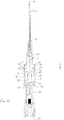
- Fig. 1 shows an IV catheter assembly 10 in accordance with the invention prior to use illustrating the tip protector assembly 12 being in its ready position.
- the catheter assembly includes a catheter tube 26 having distal 30 and proximal 28 ends and a catheter hub 24 attached to the catheter tube 26 at the proximal end 28 of the catheter tube 26.
- the catheter assembly includes a needle 14 extending through the catheter hub 24 and catheter tube 26 defining an axial direction A.
- the needle 14 has distal 30 and proximal 28 ends, wherein a sharp needle tip 18 is formed at the distal end 30 of the needle.
- a needle hub 20 is attached to the proximal end 28 of the needle.
- the catheter assembly further includes a tip protector assembly 12 movably arranged on the needle 14 in between the needle hub 20 and catheter hub 24.
- the tip protector assembly 12in a locking arrangement with the catheter hub 24 is, thus, secured outside the body of the said catheter hub 24 when the needle 14 is in its ready position.
- the needle 14 Prior to use of the catheter assembly the needle 14 extends all the way through the thorough bore 44 of the tip protector assembly 12 passing through the catheter hub 24 as well as catheter tube 26 and the needle tip 18 protrudes from a distal end 30 of the catheter tube 26. As mentioned above, this position of the needle 14 is referred to as the 'ready position' in this context.
- the needle shaft 16 has a generally constant principal profile, except for a change in profile 34, for example in the form of an enlargement 36 of the radial dimension of the needle 14 in at least one direction as compared to the principal profile.
- the change in profile 34 is provided in the region closer to the proximal end 28 of the needle.
- the change in profile 34 may be defined as a needle 14 section having a different dimension than the nominal diameter and may be created using various means and which forms an engagement means.
- the change in profile 34 can be made, for example, by crimping the needle shaft 16. The function of the engagement means will be discussed in more detail further below.
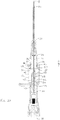
- Fig. 2A shows side view of an IV catheter assembly 10 illustrating the tip protector assembly 12 in its ready position according to one embodiment of the invention.
- the tip protector assembly 12 is movably arranged on the needle shaft 16 outside the catheter hub 24 by first locking means 52 provided in the tip protector assembly 12 engaging with the second locking means 54 provided on the outer wall 60 of the catheter hub 24.
- the first locking means 52 include one or more locking protrusions 72, for example at least a pair of part annular disc like locking protrusions 72 or at least a pair of locking lugs 76 in a direction opposing each other.
- the first locking means 52 are provided in the inner wall 58 of the hollow enclosure 32 proximal to the distal end 30.
- the second locking means 54 include locking depressions 74 in the form of for example, at least a pair of locking recess or grooves 74 or a pair of part annular grooves 74 in a direction opposing each other receiving the first locking means 52 in the ready position of the tip protector assembly 12.
- the second locking means 54 are configured on the outer wall 60 of the catheter hub 24 in a region close to the proximal end 28. It is to be noted that instead of the locking depressions 74 provided on the outer wall 60 of the catheter hub 24 it is also possible to provide one or more locking protrusions 72 or combination of either a locking protrusion 72 or a locking depression 74 in the outer wall 60 of the catheter hub 24.
- the tip protector assembly 12 includes a base portion 42 at a proximal end 28 thereof having a through bore 44 for receiving the needle 14 extending towards distal end 30 in an axial direction A.
- the first 46 and second 48 arms extend from a distal side/end 30 of the base portion 42 generally in the axial direction A.
- the profile of the through bore 44 is adapted to the principle outer profile of the needle.
- the first arm 46 is longer than the second arm 48 and has a distal section 40 which is angled towards the second arm 48 and substantially overlaps with the second arm 48, forming the angled end section 50.
- the angled end section 50 preferably has an undercut for catching the needle tip 18.
- the angled end section 50 of the first arm 46 is supported on the needle shaft 16 against a restoring force exerted by for example, a tension creating element 68.
- a tension creating element 68 Since in a preferred embodiment, the first 46 and second 48 arm is made of resilient material, such as plastic material having elastic properties, it is to be understood that the restoring force can also be exerted by the first 46 and second 48 arm.
- each of the at least one side of the inner walls 58 of the first 46 and second 48 arms of the tip protector assembly 12 has a internal recess 62 close to the base portion 42 thereof forming a cavity or cut out 64 (not shown).
- the extension of the region above the said internal recess 62 towards the distal end 30 in the axial direction A forms protective side-flap 66 ( Figs.
- the protective side-flaps 66 provided in at least one side of the first 46 and second 48 arms surround the needle shaft 16 when passing through the first 46 and second 48 arms. Moreover, the protective side-flaps 66 help prevent the needle tip 18 from protruding sideways out of the tip protector assembly 12, thereby further increasing the protective function thereof. It is to be understood that the protective side-flap 66 can be provided on the either sides of the first 46 and second 48 arms in a similar manner. Further, such recess 74 can be formed both on the inner 58 and outer 60 walls of the first 46 and second 48 arms or in a combination of the inner 58 and outer 60 walls of the first 46 and second 48 arms.
- the second locking means 54 include at least a pair of locking lugs 76 which are adapted to engage with the peripheral surface 94 forming a locking surface provided on the distal end 30 of the hollow enclosure 32 when the tip protector assembly 12 is in its ready position.
- the pair of locking lugs 76 is configured on outer wall 60 of the catheter hub 24 at the proximal end 28 in a direction opposing each other.
- first 52 and second 54 locking means help the tip protector assembly 12 to lockingly engage with the catheter hub 24being secured outside the body of the said catheter hub 24in its ready position prior to use preventing movement of the tip protector assembly 12 before the needle tip 18 is safely received inside the first 46 and second 48 arms of the tip protector assembly 12.
- the locking lugs 76 provided on the catheter hub 24 it is also possible to provide one or more locking depressions 74 or combination of either a locking lug 76 or a locking depression 74.
- the tip protector assembly 12 including first 46 and second 48 arms may be made of a transparent plastic material or transparent elastomer material or the like. For ease in understating the needle 14 has been shown passing through the through bore 44 of the base portion 42 extending in axial direction A.
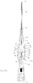
- Fig. 3A shows front view of an IV catheter assembly 10 illustrating the tip protector assembly 12 in its ready position according to another embodiment of the invention.
- the tip protector assembly 12 is movably arranged on the needle shaft 16 outside the catheter hub 24 by first locking means 52 provided in the tip protector assembly 12 engaging with the second locking means 54 provided on the outer wall 60 of the catheter hub 24.
- the first locking means 52 include one or more locking protrusions 72 in the similar manner as explained in Fig 2A and received in the second locking means 54 provided on the outer wall 60 of the catheter hub 24.
- the second locking means 54 includes locking threads 78 on the outer wall 60 of the catheter hub 24 in the region of proximal section 38.
- the locking threads 78 are configured as annular locking thread 78 or at least part annular locking thread 78 on the outer circumferential wall of the catheter hub 24.
- the locking thread 78 is adapted to engage with peripheral surface 94 of the hollow enclosure 32 provided on the distal end 30 of the hollow enclosure 32 which forms a locking surface when the tip protector assembly 12 is in its ready position.
- the first 52 and second 54 locking means are adapted to engage rotatably in at least first direction in a locking arrangement securing the tip protector assembly 12 with the catheter hub 24being secured outside the body of the said catheter hub 24in its ready position.
- the first 52 and second 54 locking means are disengaged by rotating in at least second direction opposing the first direction.
- the needle 14 has been shown passing through the through bore 44 of the base portion 42 extending in axial direction A.
- first locking means 52 may include one or more locking depressions 74 and second locking means 54 include one or more locking protrusions 72.
- first 52 and second 54 locking means include a combination of one or more locking protrusions 72 and one or more locking depressions 74.
- first 52 and second 54 locking means include one or more locking lugs 76.
- first 52 and second 54 locking means include one or more locking threads 78.
- first 52 and second 54 locking means include a combination of one or more locking lugs 76 and one or more locking threads 78.
- a tension creating element 68 may surround preferably a distal section 40 of the first 46 and second 48 arms such that deflection of at least the first arm 46 occurs mainly against a restoring force of the tension creating element 68.
- One or more locking protrusions 72 forming tapered outer surfaces 70 extending along the outer periphery of the first 46 and second 48 arms are provided in order to position the tension creating element 68 on the first and second 5 arms ( Figs 2A to 3B and 4B ).
- the tension creating element 68 is prevented from sliding off the distal sections 40 of the first 46 and second 48 arms, when the first 46 and second 48 arms are spread apart against a restoring force of the tension creating element 68.
- the tension creating element 68 may not be a separate component of the tip protector assembly 12 and can be integrally made therein.
- the tension creating element 68 partly surrounds the first 46 and second 48 arms are (not shown) of the tip protector assembly 12 i.e. instead of surrounding the two arms the tension creating elements 68 biases the two arms by a linear biasing action.
- the tension creating element 68 have the structure forming a link connecting the said first 46 and second 48 arms (not shown) and which may be positioned and/or arranged in at least one of the either sides of first 46 and second 48 arms of the tip protector assembly 12.
- the tension creating element 68 may have the structure forming a link connecting the said first 46 and second 48 arms (not shown) and which may be positioned and/or arranged in both sides of first 46 and second 48 arms of the tip protector assembly 12.
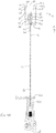
- a stopper element 80 is provided in the base portion 42 or on the distal side/end 30 of the base portion 42, for example by insert molding.
- the stopper element 80 has an axial bore 82 which is aligned with the thorough-bore 44 of the base portion 42.
- the axial bore 82 has a circular cross-section with its diameter being slightly larger than the principle diameter of the proximal section 38 of the needle shaft 16 relative to the stopper element 80. More specifically, the cross-section of the axial bore 82 of the stopper element 80 is adapted to the principal profile of the needle shaft 16 such that the stopper element 80 can slide along the needle shaft 16 with minimum friction.
- the diameter of the axial bore 82 is not only smaller than that of the needle passage 22 but also smaller than the maximum dimension of the change in profile 34 of the needle shaft 16, e.g. in the form of enlargement 36, in order to prevent the enlargement 36 from passing through the axial bore 82 and, thus, to prevent the tip protector assembly 12 from sliding off the needle.
- such a stopper element 80 would be made of a second material of a greater hardness and/or stiffness different from the first material of the base portion 42, such that the stopper element 80 withstands greater force exerted by the change in profile 34 of the needle 14 upon withdrawal of the needle 14 from the catheter, thereby more effectively preventing the change in profile 34 of the needle 14 from passing through the base portion 42 and thus more effectively preventing the tip protector assembly 12 from sliding off the needle.
- the stopper element 80 has a disk-like shape, similar to a washer or ring and is made of hard plastic, metal or ceramic and it can also be made out of any other material which is stiff and which cannot easily be distorted.
- the stopper element 80 is made from a second material which is harder and less easily distortable than the first material of the base portion 42, has the effect that the tip protector assembly 12 is secured more effectively on the needle shaft 16 and can be retained even if excessive external force is applied when pulling on the needle, as the change in profile 34 in the form of, for example an enlargement 36 acting as engagement means is prevented from being pulled through the base portion 42 of the tip protector assembly 12.
- the tip protector assembly 12 provides a better protection against accidental pricking and thus increased safety for the person handling the catheter assembly.
- stopper element 80 need not be arranged in the base portion 42 itself, but can also be arranged at the distal side/section 40 thereof between the first 46 and second 48 arms are of the tip protector assembly 12. Thus, the position of the stopper element 80 in between the first 46 and second 48 arms can be selected freely.
- the stopper element 80 may also be arranged loosely on the needle 14 between the two arms of the tip protector assembly 12 and floating on the needle shaft 16 and can be held in the area defined by the internal recess 62 of the first 46 and second 48 arms are (not shown).
- the stopper element 80 may be formed by a tube-like element. It can be held by holding means, like one or more locking protrusions or locking depressions in a predetermined section of the tip protector assembly 12, for example in a region proximal to the base portion 42 of the tip protector assembly 12.
- the stopper element 80 can be arranged in floating condition in a pre-determined section in between the first 46 and second 48 arms of the tip protector assembly 12 anywhere in between the proximal section 38 and distal section 40 thereof along the line of needle passage 22 configured therein.
- the purpose of the needle tip 18 protector assembly 12 is to cover the needle tip 18 after placement of the catheter tube 26 in and withdrawal of the needle 14 from the patient's vein.
- This position can be referred to as 'tip protecting position'.
- the needle shaft 16 moves relative to the tip protector assembly 12 being lockingly engaged with the catheter hub 24 by the first 52 and second 54 locking meansbeing secured outside the body of the said catheter hub 24 in its ready position.
- the angled end section 50 is no longer supported on the needle shaft 16 and a restoring force ensures that the first arm 46 of the needle 14 is moved back into alignment with the axial direction A into its tip protecting position so that the needle tip 18 is blocked by the angled end section 50 of the tip protector assembly 12.
- the change in profile 34 e.g. in the form of the enlargement 36 engages with the base portion 42 of the needle shaft 16 and in particular with the stopper element 80 therein such that the tip protector assembly 12 can be pulled out of the catheter hub 24 together with the needle.
- the first locking means 52 provided on the tip protector assembly 12 also disengage from the second locking means 54 provided outside the catheter hub 24, preferably by the pulling force acting on the tip protector assembly 12 via the needle 14 and the stopper element 80.
- the tip protector assembly 12 is prevented from axial movement relative to the catheter hub 24 and effectively engaged with the catheter hub 24being secured outside the body of the said catheter hub 24 when the needle 14 is in its ready positionuntil a pulling force exerted by the needle 14 on the base portion 42 of the tip protector assembly 12 via the change in profile 34 of the needle 14 upon withdrawal of the needle 14 from the catheter hub 24 becomes great enough to disengage the first locking means 52 from the second locking provided on the catheter hub 24.
- the tip protector assembly 12 is shown with further detail in Figs. 5 , 6A and 6B wherein the tip protector assembly 12 is provided with abase portion 42 having a needle passage 22 extending in the axial direction A from the proximal end 28 of the base portion 42 to a distal side of the base portion 42 with a hollow enclosure 32 formed by the extension of the base portion 42 in a direction generally parallel to the axial direction A wherein the distal end 30 of the hollow enclosure 32 has a substantially circular opening 90 allowing the needle 14 to pass there-through.
- First 46 and second 48 arms are made integrally within the hollow enclosure 32 and extend from the distal side of the base portion 42 in an axial direction A wherein the region between the first 46 and second 48 arms and the hollow enclosure 32 defines open space 56.
- First locking means 52 in the form of for example, at least a pair of part-annular locking protrusions 72 in a direction opposing each other are provided to secure the tip protector assembly 12 with the second locking means 54 provided on the catheter hub 24 such that the tip protector assembly 12secured outside the body of the said catheter hub 24 when the needle 14 is in its ready position.
- the outer profile of the tip protector assembly 12 in particular the hollow enclosure 32 has a substantially cylindrical shape or a tube like shape. It is to be noted however, that the outer profile of the tip protector assembly 12 need not necessarily be cylindrical in shape or tube like shape and can have any other shape such as a rectangular, square or any other suitable shape.
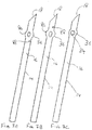
- Fig. 7A shows an embodiment of a needle 14 having a needle shaft 16, a needle tip 18 and a change in profile 34 in the form of an enlargement 36 formed for example, by a crimp.
- the crimp is made by a local depression 84 such that lateral protrusions 86 result from the crimping process.
- the crimping process is controlled such that the internal cross-sectional area of the needle 14 is not reduced substantially such that the internal profile of the needle shaft 16 is not affected.
- Fig. 7B shows the needle 14 according to Fig. 6A , however having a slit forming an opening 88 arranged slightly distally from the change in profile 34, such that it is still arranged within the catheter tube 26 in the ready position.
- the opening 88 just extends over about 0.5 mm in axial direction A and provides a thorough hole through the needle 14 wall.
- Fig. 7C shows the needle 14 according to Fig 7B , however with the slit forming an opening 88 arranged proximally from the change in profile 34.
- the opening 88 is dimensioned such that it does not affect the functioning of the tip protector assembly 12.
- the method of using the IV catheter assembly 10 can be understood whereby the catheter assembly is inserted into a patient by puncturing the skin and the vein therein of the patient with pointed tip of the needle.
- the needle 14 and catheter tube 26 are introduced into the patient's vein by the healthcare worker. Once the catheter tube 26 is securely within the vein of the patient and a successful flashback is detected, the healthcare worker withdraws the needle 14 from the vein and the catheter tube 26 simultaneously with the catheter securely lodged within the vein of the patient.
- the needle tip 18 as retracted from the catheter assembly is thereafter automatically secured in the tip protector assembly 12 being entrapped therein.
- the IV catheter assembly 10 including tip protector assembly 12 of the invention can be manufactured at reduced costs while at the same time the safety of the IV catheter assembly 10 is increased.
- the IV catheter assembly 10 including the tip protector assembly 12 is particularly inexpensive to manufacture if the base portion 42, the hollow enclosure 32 and the first 46 and second 48 arms integrally made from a first material.
- the first material may, for example, be a plastic material.
- the base portion 42, the hollow enclosure 32 and the first 46 and second 48 arms could be manufactured by injection molding.
- the base portion 42, hollow enclosure 32 and one of the first 46 and second 48 arms could be integrally made from a first material, for example a plastic material and the other one of the first 46 and second 48 arms could be made from a second material different from said first material.
- said one of the first 46 and second 48 armscould include a strip of material having spring-like properties, e.g. a strip of sheet metal or any other suitable material.
- securing the tip protector assembly 12 outside the catheter hub 24 by means of first 52 and second 54 locking is a simple measure achieving an independent and safe seat of the tip protector assembly 12 and which effectively prevents accidental removal of the tip protector assembly 12 prior to the needle tip 18 being received in the tip protector assembly 12.
- This arrangement ensures correct protective function of the tip protector assembly 12 but it also removes entirely the problem of pre-mature release faced with the needle 14 safety devices of the prior art when such needle 14 safety devices are retained inside the chamber defined by the catheter hub 24 and when retracting forces applied on the needle 14 while disengaging the needle hub 20 from the catheter hub 24.
- the risk of premature release of the tip protector assembly 12 during withdrawal of the needle 14 is substantially removed and, thus, the risk of accidental pricking by the needle 14 is reduced.
- the tip protector assembly 12 having a hollow enclosure 32 provides a safe reliable and effective automatic tip protection mechanism when the needle 14 is withdrawn from the catheter as well as a safe, reliable and effecting means and mechanism for engaging the tip protector assembly 12 in a locking arrangement with the catheter hub 24 being secured outside the body of the said catheter hub 24 when the needle 14 is in its ready position.
- the tip protector assembly 12 of an example can also be adapted such that without including the stopper element 80.
- the outer profile of the enlargement 36 on the needle shaft 16 must be greater than the profile of the thorough-bore 44 provided in the base portion 42 of the tip-protector assembly, in order to prevent the tip protector assembly 12 from sliding off the needle 14 in a distal direction.
Landscapes
- Health & Medical Sciences (AREA)
- Life Sciences & Earth Sciences (AREA)
- Engineering & Computer Science (AREA)
- Hematology (AREA)
- General Health & Medical Sciences (AREA)
- Anesthesiology (AREA)
- Biomedical Technology (AREA)
- Heart & Thoracic Surgery (AREA)
- Veterinary Medicine (AREA)
- Animal Behavior & Ethology (AREA)
- Public Health (AREA)
- Pulmonology (AREA)
- Biophysics (AREA)
- Environmental & Geological Engineering (AREA)
- Vascular Medicine (AREA)
- Media Introduction/Drainage Providing Device (AREA)
- Infusion, Injection, And Reservoir Apparatuses (AREA)
Description
- The present invention relates to a medical device such as, for example a safety intravenous (IV) catheter assembly. In particular, the invention relates to a needle tip protector assembly for safety IV catheter assembly. More particularly the present invention relates to an IV catheter assembly with improved means and mechanism for withdrawing and securing the needle tip safely inside a tip protector assembly automatically after use providing protection from accidental needle pricks.
- Medical devices such as safety IV catheter assembly are used in healthcare facilities and hospitals. ThelV catheter assembly of this kind is generally known and, for example, used to administer fluid and/or medicine to a patient or to take blood from a patient. Once a needle has been used, it becomes contaminated with the patient's blood and becomes a potential threat, especially for the health care workers, in the spread of infectious diseases. During surgery, handling of these sharp instruments can lead to accidental sticks or puncture wounds exposing the healthcare worker to the infections such as AIDS and hepatitis. The chances of needle stick are increased during an emergency with several aspects require to be handled. Likewise, during disposal, an exposed needle point may be and usually is a threat to the medical waste handler.
- Various safety IV catheter assemblies have been developed to automatically cover and shield the needle tip after its withdrawal from the patient. These assemblies have taken a number of embodiments and have various degrees of elaboration. However, the safety mechanisms implemented in these assemblies increase costs of manufacture substantially and may malfunction, especially in a fluid-filled environment where it may stick or slip. Some of the known needle protecting systems requires multiple parts, which drives up the manufacturing cost for a disposable unit. The cost-benefit requirements of the medical industry call for an inexpensive needle protecting system which is disposable along with the needle.
- Moreover, some IV catheter assemblies with the needle guard that have been developed sometimes fail to prevent occurrence of unintended needle stick injuries. Generally, in such assemblies a needle safety device or needle guard is arranged completely in a chamber defined by the catheter hub. In order to ensure correct protective function of the needle guard, it is necessary that the needle guard is secured steadily in its ready position while being secured inside in the catheter hub. However, such assemblies suffers from the problem of premature release of the needle guard from the catheter hubunder retracting forces applied on the needle while disengaging the needle hub from the catheter hub. In such a situation, the risk of accidental needle stick injury is a real threat to the users/practitioners. Moreover, such pre-mature release and un-steadiness of the needle guard in the catheter hub affects its correct and effective function protecting the tip of the needle.
- Hence, there is a constant need to address the afore-mentioned problems and to provide a medical device in particular an IV catheter assembly which provides reliable protection against accidental pricking from the sharp tip of the needle and which is easy and inexpensive to manufacture.
-
US 2009/281499 A1 discloses a needle shielding assembly. The needle shielding assembly includes a needle, a catheter adapter, a sleeve, and a safety clip. In the shown embodiment, the safety clip is modified to include at least one arm having an interlock flange at the distal end of the arm. The sleeve is modified to include at least one interlock finger channel formed on the inner surface of the sleeve. The interlock finger channel is a recessed groove formed on the inner surface of sleeve. The interlock finger channel extends from the distal end of the sleeve to the proximal end of the sleeve, and terminates in an interlock finger catch. The interlock finger catch is the terminal end of the interlock finger channel and is located at a point prior to the proximal end of the sleeve. -
WO 03/011381 A1 - Therefore, the primary object of the present invention is to provide a protective system which is simple and dependable in its deployment, inexpensive to manufacture, expedient in its operation and effective in protecting a needle tip, and which ensures correct functioning even after longer shelf life.
- It is another object of the present invention to provide an IV catheter assembly with improved means and mechanism for protection against accidental needle sticks and pricks.
- It is another object of the present invention to provide an IV catheter assembly including a catheter hub without defining a chamber;
- It is another object of the present invention to provide a tip protector assembly which can be fitted outside the catheter hub being lockingly secured therewith when the needle hub is in the retracted position.
- It is another object of the present invention to provide an IV catheter assembly having a locking mechanism to secure the tip protector assembly together with the catheter hub when the needle hub is in the retracted position.
- It is another object of the present invention to provide an IV catheter assembly having locking means to secure the tip protector assembly together with the catheter hub when the needle hub is in the retracted position.
- It is another object of the present invention is to provide an IV catheter assembly with improved means and mechanism for withdrawing and automatically securing the needle tip safely inside a tip protector assembly after use.
- It is another object of the present invention is to provide an IV catheter assembly with improved means and mechanism, which means and mechanism is irreversible once the tip protector assembly encloses the needle tip.
- It is another object of the present invention is to provide an IV catheter assembly comprising a tip protector assembly that cannot be easily pulled off the needle tip once the needle tip is covered by the said tip protector assembly by application of even excessive external force.
- Yet another object of the present invention is to provide an IV catheter assembly comprising needle safety means and mechanism that is simple in construction and cheap to manufacture.
- Still another object of the present invention is to provide an IV catheter assembly which remains compact after the needle tip has been withdrawn from the medical device assembly and secured inside a tip protector assembly.
- The present invention relates to a safety IV catheter assembly with the features according to the independent claim, including a needle tip protector assembly with improved safety means and mechanism that automatically covers the sharp tip of the needle after withdrawal of the needle from the catheter tube and catheter hub preventing accidental needle sticks and pricks of a healthcare worker by the needle tip.
- Subject-matter referred to as embodiments and/or inventions not being under the scope of the appended claims merely represent possible exemplary executions and are not part of the invention.
- The invention also relates to a tip protector assembly being arranged outside the catheter hub when the needle hub is in the retracted position.
- According to one embodiment, a safety IV catheter assembly is provided comprising:
a catheter tube having a distal end and a proximal end; a catheter hub having a distal end and a proximal end; a needle extending through the catheter hub and the catheter tube having opposite proximal and distal ends defining an axial direction, wherein the proximal end is joined to the needle hub and the distal end forms a sharp tip and a change in profile is provided between the proximal and distal ends of the needle; a tip protector assembly being arranged movably on the needle in-between the catheter hub and needle hub including: a base portion having a needle passage extending in the axial direction from the proximal end of the base portion to a distal side of the base portion; a hollow enclosure formed by the extension of the base portion in a direction generally parallel to the axial direction; wherein the distal end of the hollow enclosure has a substantially circular opening allowing the needle to pass there-through; first and second arms made integrally within the said hollow enclosure and extending from the distal side of the base portion in an axial direction, wherein the region between the first and second arms and the hollow enclosure defines open space; at least one tension creating element surrounding partially and/or completely the said first and second arms in a region proximal to the distal ends thereof; at least one stopper element arranged in the base portion having an axial bore with a dimension adapted to the principal outer profile of the said needle; and one or more first locking means to lockingly engage the tip protector assembly outside the catheter hub in an arrangement engaging with one or more second locking means provided on the catheter hub in its ready position, wherein the first arm is deflected radially outwards by the needle against a restoring force. - Preferably, the outer profile of the tip protector assembly in particular the hollow enclosure has a substantially cylindrical shape or a tube like shape. It is to be noted however, that the outer profile of the tip protector assembly need not necessarily be cylindrical in shape or tube like shape and can have any other shape such as a rectangular, square or any other suitable shape.
- According to an embodiment, the hollow enclosure may be defined as a circular wall surrounding the first and second arms of the tip protector assembly. The distal end of the hollow enclosure has a peripheral surface which acts as a locking surface to engage with one or more second locking means provided on the catheter hub when the tip protector assembly is in its ready position.
- According to an embodiment, the first locking means provided on the tip protector assembly include one or more locking protrusions, for example disc-like locking protrusion or at least part annular disc like locking protrusion or combination thereof provided in a distal region on the inner surface of the hollow enclosure of the tip protector assembly. According to a preferred embodiment, the protrusion is of part-circular, in particular semi-circular shape. The locking protrusions are adapted to engage with second locking means provided on the outer wall of the catheter hub. The second locking means include one or more locking depressions for example, a locking recess/groove or at least part annular locking recess/groove or combination thereof.
- According to an embodiment, the first locking means include one or more locking depressions and second locking means include one or more locking protrusions.
- According to an embodiment, the first and second locking means include a combination of one or more locking protrusions and one or more locking depressions.
- According to an embodiment, the first and second locking means include one or more locking lugs.
- According to an embodiment, the first and second locking means include one or more locking threads.
- According to an embodiment, the first and second locking means include a combination of one or more locking lugs and one or more locking threads.
- According to an embodiment, the first and second locking means are adapted to engage rotatably in at least first direction in a locking arrangement securing the tip protector with the catheter hubbeing secured outside the body of the said catheter hub when the needle is in its ready position. In order to disengage the tip protector assembly in its tip protecting position from the catheter hub, the first and second locking means are disengaged by rotating in at least second direction opposing the first direction.
- According to an embodiment, the first arm includes a first free end and the second arm includes a second free end extending generally axially in a distal direction from the base portion. The first free end extends beyond the second free end and overlaps the second free end by an angled end section including a length and width configured to retain the tip of the needle within a tip holding space so that in protected position the angled end section abuts the needle, in particular the tip of the needle. The length and width of the angled end section are larger than the maximum outer profile of the needle and/or its diameter and adapted to confine the needle tip within a tip holding space.
- As a preferred alternative, angled end section of the first arm may have an undercut for catching the needle tip. Further, the portion forming the angled end section may be made of a second material different from the first material forming, for example the first and second arms of the tip protector assembly such that harder plastic material or portion reinforced with metal material or the like so that the needle abutting the angled end section cannot pierce through it and be retained firmly in the needle tip holding space even under application of excessive force.
- According to an embodiment, each of the at least one side of the inner walls of the first and second arms of the tip protector assembly has internal recess close to the base portion thereof forming a cavity or cut out. The extension of the region above the said internal recess towards the distal end in the axial direction forms protective side-flaps in at least one side thereof providing an enclosure for the needle passing therethrough. The protective side-flaps provided on the first and second arms surround the needle shaft when passing through the first and second arms. The distal end of each of the internal recess in the first and second arms defines a shoulder. The side-flaps help prevent the needle tip from protruding sideways out of the tip protector assembly, thereby further increasing the protective function thereof. Moreover, the internal recesses provided in the arms facilitate deflectability and also improves restoration capabilities thereof. In particular, the internal recess provided in the first arm helps in improving deflectability as well as the restoration properties of first arm when the distal angled end thereof is no longer supported on the needle shaft. Thus, the internal recess increases the deflectability of the arms in the regions it is provided and thereby reduces the restoring force acting thereon, in particular on the angled end section of the first arm while it is being supported by the needle shaft. This allows the needle to be moved more easily relative to the first and second arms and in particular relative to the angled end section, as the frictional force acting on the needle is reduced. In the embodiment, where a floating stopper element e.g. a floating disk or washer is provided as a stopper element the shoulder formed by distal end of the said internal recess in the first and second arms act as movement limiting means.
- According to an embodiment, a tension creating element surrounds the first and second arms of the tip protector assembly, for example an elastic band in between the proximal and distal region of the first and second arms, in particular in a region proximal to the distal end of the first and second arms. The tension creating element exerts a restoring force on the first and second arms when tip protector assembly is in its ready position i.e. when the first and second arms are spread apart by the needle extending all the way through the tip protector assembly. Once the needle shaft no longer supports the angled end section of the first arm i.e. when the tip protector assembly is in its tip protecting position, the tension creating element aids the repositioning of the first arm back into axial alignment with the axial direction. This repositioning is necessary so that the angled end section can block the needle tip from axially sliding out of the tip protector assembly. In addition, the tension creating element defines a tip holding enclosure between the first and second arms and thus helps to prevent the needle shaft and the needle tip from protruding sideways out of the tip protector assembly. Thus, the tension creating element adds to the protective effect of the tip protector assembly.
- In a preferred alternative, the tension creating element partly surrounds the first and second arms of the tip protector assembly i.e. instead of surrounding the two arms the tension creating elements biases the two arms by a linear biasing action.
- In another preferred alternative, the tension creating element have the structure forming a link connecting the said first and second arms and which may be positioned and/or arranged in at least one of the either sides of first and second arms of the tip protector assembly.
- In yet another preferred alternative, the tension creating element may have the structure forming a link connecting the said first and second arms and which may be positioned and/or arranged in both sides of first and second arms of the tip protector assembly.
- In one embodiment, the tension creating element includes the structure in the form of a ring.
- In one embodiment, the tension creating element may not be a separate component of the tip protector assembly and can be integrally made therein. It may be made from an elastic material and/or materials having elastic properties, for example, silicone, rubber or the like.
- In one embodiment, the tension creating element may be arranged or positioned in any of the region in between the proximal and distal regions of the first and second arms of the tip protector assembly.
- The change in profile may be defined as a needle section having a different dimension than the nominal diameter and may be created using various means. The change in profile may be for example, an enlargement and it may be made by crimping a portion of the needle either only on one side or point on the circumference of the needle or alternatively along both sides or symmetrically along the circumference of the needle.
- In a preferred alternative, the change in profile may be formed in the form of a shoulder, bulge formed as an annular widening and by adding material onto the outer surface of the needle or by adding a sleeve to the needle for example, by welding, gluing or soldering etc. The added material may include a metal material, a plastic material, adhesive, resin or the like. In the case of the added material being metal material, the change in profile may, for example, be formed by build-up welding or by soldering of the additional material onto the needle. Alternatively, the additional material could be glued to the needle. The change in profile in the form of an enlargement may be referred to as a crimp, a sleeve, annular sleeve, part annular sleeve, a bulge, a section of the needle with added material or combinations thereof. Further, the inner profile of the needle can either be reduced in the region of the change in profile, for example, if the change in profile is formed by crimping, or it can be substantially constant throughout the length of the needle, for example, if the change in profile is formed by applying additional material to the needle shaft.
- In one embodiment, the needle shaft may also be formed with a slit forming an opening arranged distally or proximally from the change in profile therein. The opening may be formed by a small slit which is cut into the needle shaft and which extends in axial direction for a small distance, for example 0.3 to 1mm. The opening is just large enough in order to provide an early blood flashback function close to the needle tip within the catheter tube such that the medical practitioner can recognize that needle has been placed correctly within the patient's vein. In case of correct, positioning of the needle, blood pours out of the opening within the needle shaft into the space between the needle shaft and the inner wall of the transparent catheter tube and visible to the medical practitioner.
- In the invention a groove is provided either in the inner wall of one of the first and second arms extending substantially in the axial direction from the base portion. The groove acts as a guide groove for the needle shaft and aids the axial movement of the needle shaft relative to the tip protector assembly. Moreover, the needle shaft is prevented from sliding sideways, in particular off the angled end section of the first arm. Such a sideways movement would significantly increase the force required to move the needle shaft relative to the tip protector assembly, which would prevent a correct functioning of the tip protector assembly. Alternatively, the guide groove can be provided in both the first and second arms.
- In one embodiment, the tip protector assembly is made from a unitary plastic material or, or an elastomer or thermoplastic or any combination thereof such as thermoplastic elastomer. In other embodiments, the tip protector assembly is made from multi-pieces and includes materials such as metal and/or plastic or any combination thereof. For example, either of the first and second arms or both may be made of a resilient material or plastic material or metal material or combination thereof.
- In one embodiment, the stopper element is arranged within the base portion and can be integrally formed within the base portion of the tip protector assembly. The stopper element is made of a second material different from a first material of the base portion and has a through-bore with a profile which is adapted to the principal outer profile of the needle shaft. Preferably, the stopper element defines an axial bore having a cross-section adapted to the principal profile of the needle but being smaller than the radial dimension of the change in profile in the form of an enlargement forming the engagement means configured on the needle shaft. The stopper element is preferably arranged such that its axial-bore is in general alignment with the needle passage of the tip protector assembly.
- According to an embodiment, the stopper element surrounds the needle. The length of the stopper element, i.e. its dimension seen in the axial direction, may vary. As such, the stopper element can, for example, be disk or a ring or a washer or a tube. However, it is to be understood that the outer profile of the stopper element does not have to have a circular outer profile. It is also possible that the outer profile of the stopper element is of non-circular form, for example, of oval or polygonal shape or other suitable geometric shape.
- According to an alternative, it is also possible that the stopper element only partly surrounds the needle. In this case, the stopper element could have the shape of a slotted disk, ring or tube.
- As yet another preferred alternative, the stopper element may also be arranged loosely on the needle between the two arms of the tip protector assembly and floating on the needle shaft and can be held in the area defined by the internal recess of the first and second arms. As such the stopper element may be formed by a tube-like element. It can be held by holding means, like one or more locking protrusions or locking depressions in a predetermined section of the tip protector assembly, for example in a region proximal to the base portion of the tip protector assembly. Alternatively, the stopper element can be arranged in floating condition in a pre-determined section in between the first and second arms of the tip protector assembly anywhere in between the proximal section and distal section thereof along the line of needle passage configured therein.
- To define the reference to first material and second material as used herein, preferably, the second material is of greater hardness and/or stiffness than the first material. For example, the first material could be a plastic material and the second material could consist of a metal, a harder fiber material, a rubber material or a ceramic, or any other type of suitable material which is stiff and not as easily distortable as the first material.
- Yet another example of the present disclosure relates to methods of making/ assembling and using an IV catheter assembly including the tip protector assembly when the tip protector assembly is in its ready position.
- Further advantageous embodiments of the invention and preferred assemblies for carrying out the invention are disclosed in connection with the accompanying drawings.
- The present invention will now be explained in more detail in the following with reference to preferred embodiments and to the accompanying drawings in which are shown:
-
Fig. 1 illustrates an IV catheter assembly in accordance with the present invention illustrating the tip protector assembly in its ready position; -
Fig. 2A is a sectional illustration of the side view of an IV catheter assembly in accordance with the present invention illustrating the tip protector assembly in its ready position; -
Fig. 2B is a sectional illustration of the front view of an IV catheter assembly in accordance with the present invention illustrating the tip protector assembly ofFig. 2A in its ready position; -
Fig. 3A is a sectional illustration of the front view of an IV catheter assembly in accordance with the present invention illustrating the tip protector assembly in its ready position in an another embodiment; -
Fig. 3B is a sectional illustration of the side view of an IV catheter assembly in accordance with the present invention illustrating the tip protector assembly ofFig. 3A in its ready position; -
Fig. 4A illustrates a needle, needle hub and tip protector assembly in its protective position being removed from the IV catheter assembly ofFig. 1 ; -
Fig. 4B is a sectional illustration of a needle, needle hub and tip protector assembly in its protective position being removed from the IV catheter assembly ofFig. 1 ; -
Fig. 5 - illustrate sectional illustration of tip protector assembly ofFig. 1 wherein the tension creating element has been omitted for the sake of clarity; -
Figs. 6A - 6B illustrate the tip protector assembly ofFig. 1 wherein the tension creating element has been omitted for the sake of clarity; -
Fig. 7A - 7C are illustrations of different embodiments of the needles. - As used herein, the term 'proximal' refers to a region of the assembly/device or a location on the assembly/device which is closest to, for example, a medical practitioner using the assembly/device. In contrast to this, the term 'distal' refers to a region of the assembly/device which is farthest from the medical practitioner, for example, the distal region of a needle will be the region of a needle containing the needle tip which is to be inserted e.g. into a patient's vein.
- Further, as used herein the term first and second are merely identifiers and do not necessarily limit and/or restrict the features with such identifiers. For example, when viewed from another perspective, the first arm may be called the second arm and vice-versa.
- The various embodiments of present invention are directed to an IV catheter assembly including a tip protector assembly.
-
Fig. 1 shows anIV catheter assembly 10 in accordance with the invention prior to use illustrating thetip protector assembly 12 being in its ready position. The catheter assembly includes acatheter tube 26 having distal 30 and proximal 28 ends and acatheter hub 24 attached to thecatheter tube 26 at theproximal end 28 of thecatheter tube 26. The catheter assembly includes aneedle 14 extending through thecatheter hub 24 andcatheter tube 26 defining an axial direction A. Theneedle 14 has distal 30 and proximal 28 ends, wherein asharp needle tip 18 is formed at thedistal end 30 of the needle. Aneedle hub 20 is attached to theproximal end 28 of the needle. The catheter assembly further includes atip protector assembly 12 movably arranged on theneedle 14 in between theneedle hub 20 andcatheter hub 24. As shown, the tip protector assembly 12in a locking arrangement with thecatheter hub 24 is, thus, secured outside the body of the saidcatheter hub 24 when theneedle 14 is in its ready position.Prior to use of the catheter assembly theneedle 14 extends all the way through the thorough bore 44 of thetip protector assembly 12 passing through thecatheter hub 24 as well ascatheter tube 26 and theneedle tip 18 protrudes from adistal end 30 of thecatheter tube 26. As mentioned above, this position of theneedle 14 is referred to as the 'ready position' in this context. - The
needle shaft 16 has a generally constant principal profile, except for a change inprofile 34, for example in the form of anenlargement 36 of the radial dimension of theneedle 14 in at least one direction as compared to the principal profile. Preferably, the change inprofile 34 is provided in the region closer to theproximal end 28 of the needle. The change inprofile 34 may be defined as aneedle 14 section having a different dimension than the nominal diameter and may be created using various means and which forms an engagement means. The change inprofile 34 can be made, for example, by crimping theneedle shaft 16. The function of the engagement means will be discussed in more detail further below. -
Fig. 2A shows side view of anIV catheter assembly 10 illustrating thetip protector assembly 12 in its ready position according to one embodiment of the invention. As shown thetip protector assembly 12 is movably arranged on theneedle shaft 16 outside thecatheter hub 24 by first locking means 52 provided in thetip protector assembly 12 engaging with the second locking means 54 provided on theouter wall 60 of thecatheter hub 24. The first locking means 52 include one ormore locking protrusions 72, for example at least a pair of part annular disc like lockingprotrusions 72 or at least a pair of locking lugs 76 in a direction opposing each other. The first locking means 52 are provided in theinner wall 58 of thehollow enclosure 32 proximal to thedistal end 30. The second locking means 54 include locking depressions 74 in the form of for example, at least a pair of locking recess or grooves 74 or a pair of part annular grooves 74 in a direction opposing each other receiving the first locking means 52 in the ready position of thetip protector assembly 12. The second locking means 54 are configured on theouter wall 60 of thecatheter hub 24 in a region close to theproximal end 28. It is to be noted that instead of the locking depressions 74 provided on theouter wall 60 of thecatheter hub 24 it is also possible to provide one ormore locking protrusions 72 or combination of either a lockingprotrusion 72 or a locking depression 74 in theouter wall 60 of thecatheter hub 24. - As can be seen, the region between the first 46 and second 48 arms and the
hollow enclosure 32 defines open space 56. Thetip protector assembly 12 includes abase portion 42 at aproximal end 28 thereof having a through bore 44 for receiving theneedle 14 extending towardsdistal end 30 in an axial direction A. The first 46 and second 48 arms extend from a distal side/end 30 of thebase portion 42 generally in the axial direction A. The profile of the through bore 44 is adapted to the principle outer profile of the needle. Thefirst arm 46 is longer than thesecond arm 48 and has adistal section 40 which is angled towards thesecond arm 48 and substantially overlaps with thesecond arm 48, forming theangled end section 50. Theangled end section 50 preferably has an undercut for catching theneedle tip 18. In its ready position, theangled end section 50 of thefirst arm 46 is supported on theneedle shaft 16 against a restoring force exerted by for example, atension creating element 68. Since in a preferred embodiment, the first 46 and second 48 arm is made of resilient material, such as plastic material having elastic properties, it is to be understood that the restoring force can also be exerted by the first 46 and second 48 arm. - In contrast to the
first arm 46 and because of lack of distalangled end section 50, thesecond arm 48 has less deflectablitly than thefirst arm 46 when theneedle 14 extends through thetip protector assembly 12. Nevertheless, in order to facilitate deflectability of both the first 46 and second 48 arms, each of the at least one side of theinner walls 58 of the first 46 and second 48 arms of thetip protector assembly 12 has a internal recess 62 close to thebase portion 42 thereof forming a cavity or cut out 64 (not shown). The extension of the region above the said internal recess 62 towards thedistal end 30 in the axial direction A forms protective side-flap 66 (Figs. 2A to 3B ) in at least one side thereof providing an enclosure for theneedle 14 passing therethrough in both the first 46 and second 48 arms. The protective side-flaps 66 provided in at least one side of the first 46 and second 48 arms surround theneedle shaft 16 when passing through the first 46 and second 48 arms. Moreover, the protective side-flaps 66 help prevent theneedle tip 18 from protruding sideways out of thetip protector assembly 12, thereby further increasing the protective function thereof. It is to be understood that the protective side-flap 66 can be provided on the either sides of the first 46 and second 48 arms in a similar manner. Further, such recess 74 can be formed both on the inner 58 and outer 60 walls of the first 46 and second 48 arms or in a combination of the inner 58 and outer 60 walls of the first 46 and second 48 arms. - As shown in
Fig. 2B , in addition to at least a pair of grooves or recess 74 the second locking means 54 include at least a pair of locking lugs 76 which are adapted to engage with theperipheral surface 94 forming a locking surface provided on thedistal end 30 of thehollow enclosure 32 when thetip protector assembly 12 is in its ready position. As shown, the pair of locking lugs 76 is configured onouter wall 60 of thecatheter hub 24 at theproximal end 28 in a direction opposing each other. The engagement of the first 52 and second 54 locking means help thetip protector assembly 12 to lockingly engage with the catheter hub 24being secured outside the body of the said catheter hub 24in its ready position prior to use preventing movement of thetip protector assembly 12 before theneedle tip 18 is safely received inside the first 46 and second 48 arms of thetip protector assembly 12. It is to be noted that instead of the locking lugs 76 provided on thecatheter hub 24 it is also possible to provide one or more locking depressions 74 or combination of either a lockinglug 76 or a locking depression 74. Further as shown, it is to be understood that thetip protector assembly 12 including first 46 and second 48 arms may be made of a transparent plastic material or transparent elastomer material or the like. For ease in understating theneedle 14 has been shown passing through the through bore 44 of thebase portion 42 extending in axial direction A. -
Fig. 3A shows front view of anIV catheter assembly 10 illustrating thetip protector assembly 12 in its ready position according to another embodiment of the invention. As shown thetip protector assembly 12 is movably arranged on theneedle shaft 16 outside thecatheter hub 24 by first locking means 52 provided in thetip protector assembly 12 engaging with the second locking means 54 provided on theouter wall 60 of thecatheter hub 24. The first locking means 52 include one ormore locking protrusions 72 in the similar manner as explained inFig 2A and received in the second locking means 54 provided on theouter wall 60 of thecatheter hub 24. - As shown in
Fig 3B , in addition to at least a pair of grooves 74 the second locking means 54 includes locking threads 78 on theouter wall 60 of thecatheter hub 24 in the region ofproximal section 38. The locking threads 78 are configured as annular locking thread 78 or at least part annular locking thread 78 on the outer circumferential wall of thecatheter hub 24. The locking thread 78 is adapted to engage withperipheral surface 94 of thehollow enclosure 32 provided on thedistal end 30 of thehollow enclosure 32 which forms a locking surface when thetip protector assembly 12 is in its ready position. As such, the first 52 and second 54 locking means are adapted to engage rotatably in at least first direction in a locking arrangement securing thetip protector assembly 12 with the catheter hub 24being secured outside the body of the said catheter hub 24in its ready position. In order to disengage thetip protector assembly 12 from thecatheter hub 24 when thetip protector assembly 12 is in its tip protecting position, the first 52 and second 54 locking means are disengaged by rotating in at least second direction opposing the first direction. For ease in understating theneedle 14 has been shown passing through the through bore 44 of thebase portion 42 extending in axial direction A. - It is to be noted that the first locking means 52 may include one or more locking depressions 74 and second locking means 54 include one or
more locking protrusions 72. As another alternative, the first 52 and second 54 locking means include a combination of one ormore locking protrusions 72 and one or more locking depressions 74. As another alternative, the first 52 and second 54 locking means include one or more locking lugs 76. As another alternative, the first 52 and second 54 locking means include one or more locking threads 78. As yet another alternative, the first 52 and second 54 locking means include a combination of one or more locking lugs 76 and one or more locking threads 78. - Even though the first 46 and second 48 arms have certain elastic properties, a
tension creating element 68, for example a rubber band, may surround preferably adistal section 40 of the first 46 and second 48 arms such that deflection of at least thefirst arm 46 occurs mainly against a restoring force of thetension creating element 68. One ormore locking protrusions 72 forming tapered outer surfaces 70 extending along the outer periphery of the first 46 and second 48 arms are provided in order to position thetension creating element 68 on the first and second 5 arms (Figs 2A to 3B and4B ). Because of the tapered outer surfaces 70 thetension creating element 68 is prevented from sliding off thedistal sections 40 of the first 46 and second 48 arms, when the first 46 and second 48 arms are spread apart against a restoring force of thetension creating element 68. In a preferred alternative, thetension creating element 68 may not be a separate component of thetip protector assembly 12 and can be integrally made therein. - In another preferred alternative, the
tension creating element 68 partly surrounds the first 46 and second 48 arms are (not shown) of thetip protector assembly 12 i.e. instead of surrounding the two arms thetension creating elements 68 biases the two arms by a linear biasing action. In another preferred alternative, thetension creating element 68 have the structure forming a link connecting the said first 46 and second 48 arms (not shown) and which may be positioned and/or arranged in at least one of the either sides of first 46 and second 48 arms of thetip protector assembly 12. In yet another preferred alternative, thetension creating element 68 may have the structure forming a link connecting the said first 46 and second 48 arms (not shown) and which may be positioned and/or arranged in both sides of first 46 and second 48 arms of thetip protector assembly 12. - As is best seen in
Figs. 2A to 3B ,4B and5 , a stopper element 80 is provided in thebase portion 42 or on the distal side/end 30 of thebase portion 42, for example by insert molding. The stopper element 80 has an axial bore 82 which is aligned with the thorough-bore 44 of thebase portion 42. The axial bore 82 has a circular cross-section with its diameter being slightly larger than the principle diameter of theproximal section 38 of theneedle shaft 16 relative to the stopper element 80. More specifically, the cross-section of the axial bore 82 of the stopper element 80 is adapted to the principal profile of theneedle shaft 16 such that the stopper element 80 can slide along theneedle shaft 16 with minimum friction. At the same time the diameter of the axial bore 82 is not only smaller than that of the needle passage 22 but also smaller than the maximum dimension of the change inprofile 34 of theneedle shaft 16, e.g. in the form ofenlargement 36, in order to prevent theenlargement 36 from passing through the axial bore 82 and, thus, to prevent thetip protector assembly 12 from sliding off the needle. - Preferably, such a stopper element 80 would be made of a second material of a greater hardness and/or stiffness different from the first material of the
base portion 42, such that the stopper element 80 withstands greater force exerted by the change inprofile 34 of theneedle 14 upon withdrawal of theneedle 14 from the catheter, thereby more effectively preventing the change inprofile 34 of theneedle 14 from passing through thebase portion 42 and thus more effectively preventing thetip protector assembly 12 from sliding off the needle. Preferably, the stopper element 80 has a disk-like shape, similar to a washer or ring and is made of hard plastic, metal or ceramic and it can also be made out of any other material which is stiff and which cannot easily be distorted. - The fact that the stopper element 80 is made from a second material which is harder and less easily distortable than the first material of the
base portion 42, has the effect that thetip protector assembly 12 is secured more effectively on theneedle shaft 16 and can be retained even if excessive external force is applied when pulling on the needle, as the change inprofile 34 in the form of, for example anenlargement 36 acting as engagement means is prevented from being pulled through thebase portion 42 of thetip protector assembly 12. Hence, it is less likely that thetip protector assembly 12 is removed from theneedle tip 18 accidentally and, as a result, thetip protector assembly 12 provides a better protection against accidental pricking and thus increased safety for the person handling the catheter assembly. - Further, it is to be understood, that the stopper element 80 need not be arranged in the
base portion 42 itself, but can also be arranged at the distal side/section 40 thereof between the first 46 and second 48 arms are of thetip protector assembly 12. Thus, the position of the stopper element 80 in between the first 46 and second 48 arms can be selected freely. - As a preferred alternative, the stopper element 80 may also be arranged loosely on the
needle 14 between the two arms of thetip protector assembly 12 and floating on theneedle shaft 16 and can be held in the area defined by the internal recess 62 of the first 46 and second 48 arms are (not shown). As such the stopper element 80 may be formed by a tube-like element. It can be held by holding means, like one or more locking protrusions or locking depressions in a predetermined section of thetip protector assembly 12, for example in a region proximal to thebase portion 42 of thetip protector assembly 12. Alternatively, the stopper element 80 can be arranged in floating condition in a pre-determined section in between the first 46 and second 48 arms of thetip protector assembly 12 anywhere in between theproximal section 38 anddistal section 40 thereof along the line of needle passage 22 configured therein. - As shown in
Figs. 4A and4B , the purpose of theneedle tip 18protector assembly 12 is to cover theneedle tip 18 after placement of thecatheter tube 26 in and withdrawal of theneedle 14 from the patient's vein. This position can be referred to as 'tip protecting position'. When theneedle 14 is withdrawn from thecatheter tube 26 andcatheter hub 24 theneedle shaft 16 moves relative to thetip protector assembly 12 being lockingly engaged with thecatheter hub 24 by the first 52 and second 54 locking meansbeing secured outside the body of the saidcatheter hub 24 in its ready position. Once theneedle tip 18 is received in thetip protector assembly 12 and passes theangled end section 50 of thefirst arm 46, at this point theangled end section 50 is no longer supported on theneedle shaft 16 and a restoring force ensures that thefirst arm 46 of theneedle 14 is moved back into alignment with the axial direction A into its tip protecting position so that theneedle tip 18 is blocked by theangled end section 50 of thetip protector assembly 12. - At the same time, it is to be understood that the change in
profile 34 e.g. in the form of theenlargement 36 engages with thebase portion 42 of theneedle shaft 16 and in particular with the stopper element 80 therein such that thetip protector assembly 12 can be pulled out of thecatheter hub 24 together with the needle. In such position, the first locking means 52 provided on thetip protector assembly 12 also disengage from the second locking means 54 provided outside thecatheter hub 24, preferably by the pulling force acting on thetip protector assembly 12 via theneedle 14 and the stopper element 80. An axial movement of theneedle 14 relative to thetip protector assembly 12 is now limited, as theangled end section 50 blocks theneedle tip 18 and thebase portion 42 in particular the stopper element 80 therein prevents theneedle tip 18 from being removed via thebase portion 42 and thus theneedle tip 18 is safely surrounded by thetip protector assembly 12, as is shown inFigs. 4A and4B . - It is to be understood that because of the engagement between the first locking means 52 and second locking means 54, the
tip protector assembly 12 is prevented from axial movement relative to thecatheter hub 24 and effectively engaged with the catheter hub 24being secured outside the body of the saidcatheter hub 24 when theneedle 14 is in its ready positionuntil a pulling force exerted by theneedle 14 on thebase portion 42 of thetip protector assembly 12 via the change inprofile 34 of theneedle 14 upon withdrawal of theneedle 14 from thecatheter hub 24 becomes great enough to disengage the first locking means 52 from the second locking provided on thecatheter hub 24. - The
tip protector assembly 12 is shown with further detail inFigs. 5 ,6A and6B wherein thetip protector assembly 12 is provided withabase portion 42 having a needle passage 22 extending in the axial direction A from theproximal end 28 of thebase portion 42 to a distal side of thebase portion 42 with ahollow enclosure 32 formed by the extension of thebase portion 42 in a direction generally parallel to the axial direction A wherein thedistal end 30 of thehollow enclosure 32 has a substantially circular opening 90 allowing theneedle 14 to pass there-through. First 46 and second 48 arms are made integrally within thehollow enclosure 32 and extend from the distal side of thebase portion 42 in an axial direction A wherein the region between the first 46 and second 48 arms and thehollow enclosure 32 defines open space 56. First locking means 52 in the form of for example, at least a pair of part-annular locking protrusions 72 in a direction opposing each other are provided to secure thetip protector assembly 12 with the second locking means 54 provided on thecatheter hub 24 such that the tip protector assembly 12secured outside the body of the saidcatheter hub 24 when theneedle 14 is in its ready position. The outer profile of thetip protector assembly 12 in particular thehollow enclosure 32 has a substantially cylindrical shape or a tube like shape. It is to be noted however, that the outer profile of thetip protector assembly 12 need not necessarily be cylindrical in shape or tube like shape and can have any other shape such as a rectangular, square or any other suitable shape. -
Fig. 7A shows an embodiment of aneedle 14 having aneedle shaft 16, aneedle tip 18 and a change inprofile 34 in the form of anenlargement 36 formed for example, by a crimp. The crimp is made by alocal depression 84 such thatlateral protrusions 86 result from the crimping process. Preferably, the crimping process is controlled such that the internal cross-sectional area of theneedle 14 is not reduced substantially such that the internal profile of theneedle shaft 16 is not affected. -
Fig. 7B shows theneedle 14 according toFig. 6A , however having a slit forming an opening 88 arranged slightly distally from the change inprofile 34, such that it is still arranged within thecatheter tube 26 in the ready position. The opening 88 just extends over about 0.5 mm in axial direction A and provides a thorough hole through theneedle 14 wall. Thereby, an early blood flashback within thetransparent catheter tube 26 can be achieved when theneedle 14 is positioned into the patient's vein. Based on this blood flashback, the practitioner can see right after puncturing the patient whether theneedle 14 has been positioned correctly due to a small amount of patient's blood oozing out the space between theneedle shaft 16 and the transparent catheter shaft. -
Fig. 7C shows theneedle 14 according toFig 7B , however with the slit forming an opening 88 arranged proximally from the change inprofile 34. The opening 88 is dimensioned such that it does not affect the functioning of thetip protector assembly 12. - The method of using the
IV catheter assembly 10 can be understood whereby the catheter assembly is inserted into a patient by puncturing the skin and the vein therein of the patient with pointed tip of the needle. Theneedle 14 andcatheter tube 26 are introduced into the patient's vein by the healthcare worker. Once thecatheter tube 26 is securely within the vein of the patient and a successful flashback is detected, the healthcare worker withdraws theneedle 14 from the vein and thecatheter tube 26 simultaneously with the catheter securely lodged within the vein of the patient. Theneedle tip 18 as retracted from the catheter assembly is thereafter automatically secured in thetip protector assembly 12 being entrapped therein. - The
IV catheter assembly 10 includingtip protector assembly 12 of the invention can be manufactured at reduced costs while at the same time the safety of theIV catheter assembly 10 is increased. TheIV catheter assembly 10 including thetip protector assembly 12 is particularly inexpensive to manufacture if thebase portion 42, thehollow enclosure 32 and the first 46 and second 48 arms integrally made from a first material. The first material may, for example, be a plastic material. Thus, thebase portion 42, thehollow enclosure 32 and the first 46 and second 48 arms could be manufactured by injection molding. - Alternatively, the
base portion 42,hollow enclosure 32 and one of the first 46 and second 48 arms could be integrally made from a first material, for example a plastic material and the other one of the first 46 and second 48 arms could be made from a second material different from said first material. For example, said one of the first 46 and second 48 armscould include a strip of material having spring-like properties, e.g. a strip of sheet metal or any other suitable material. - It is to be understood that securing the
tip protector assembly 12 outside thecatheter hub 24 by means of first 52 and second 54 locking is a simple measure achieving an independent and safe seat of thetip protector assembly 12 and which effectively prevents accidental removal of thetip protector assembly 12 prior to theneedle tip 18 being received in thetip protector assembly 12. Not only this arrangement ensures correct protective function of thetip protector assembly 12 but it also removes entirely the problem of pre-mature release faced with theneedle 14 safety devices of the prior art whensuch needle 14 safety devices are retained inside the chamber defined by thecatheter hub 24 and when retracting forces applied on theneedle 14 while disengaging theneedle hub 20 from thecatheter hub 24. Hence, in the present invention the risk of premature release of thetip protector assembly 12 during withdrawal of theneedle 14 is substantially removed and, thus, the risk of accidental pricking by theneedle 14 is reduced. - Thus, the catheter assembly of the present invention provides many advantages over prior art. The
tip protector assembly 12 having ahollow enclosure 32 provides a safe reliable and effective automatic tip protection mechanism when theneedle 14 is withdrawn from the catheter as well as a safe, reliable and effecting means and mechanism for engaging thetip protector assembly 12 in a locking arrangement with thecatheter hub 24 being secured outside the body of the saidcatheter hub 24 when theneedle 14 is in its ready position. - Although this invention has been disclosed in the context of certain preferred embodiments and examples, it will be understood by those skilled in the art that the present invention extends beyond the specifically disclosed embodiments to other alternative embodiments and/or uses of the invention. For example, the
tip protector assembly 12 of an example can also be adapted such that without including the stopper element 80. In this case, the outer profile of theenlargement 36 on theneedle shaft 16 must be greater than the profile of the thorough-bore 44 provided in thebase portion 42 of the tip-protector assembly, in order to prevent thetip protector assembly 12 from sliding off theneedle 14 in a distal direction. Thus, from the foregoing description, it will be apparent to one of ordinary skill in the art that many changes and modifications can be made thereto without departing from the scope of the invention as set forth herein. - Accordingly, it is not intended that the scope of the foregoing description be limited to the exact description set forth above, but rather that such description be construed as encompassing all of the features of patentable novelty that reside in the present invention. Thus, it is intended that the scope of the present invention herein disclosed should not be limited by the particular disclosed embodiments described above.
-
- 10
- IV catheter assembly
- 12
- tip protector assembly
- 14
- needle
- 16
- needle shaft
- 18
- needle tip
- 20
- needle hub
- 22
- needle passage
- 24
- catheter hub
- 26
- catheter tube
- 28
- proximal end
- 30
- distal end
- 32
- hollow enclosure
- 34
- change in profile
- 36
- enlargement
- 38
- proximal section
- 40
- distal section
- 42
- base portion
- 44
- thorough bore
- 46
- first arm
- 48
- second arm
- 50
- angled end section
- 52
- first locking means
- 54
- second locking means
- 56
- open space
- 58
- inner wall
- 60
- outer wall
- 62
- internal recess
- 64
- cavity or cut out
- 66
- protective side flap
- 68
- tension creating element
- 70
- tapered outer surface
- 72
- locking protrusion
- 74
- locking depression/grooves/recess
- 76
- locking lug
- 78
- locking thread
- 80
- stopper element
- 82
- axial bore
- 84
- local depression
- 86
- lateral protrusion
- 88
- opening
- 90
- circular opening
- 92
- circular wall
- 94
- peripheral surface
- A
- axial direction
Claims (15)
- A safety IV catheter assembly (10) comprising:a catheter tube (26) having a distal end (30) and a proximal end (28);a catheter hub (24) having a distal end (30) and a proximal end (28);a needle (14) with a needle shaft (16) extending through the catheter hub (24) and the catheter tube (26) having opposite proximal (28) and distal ends (30) defining an axial direction (A), wherein the proximal end (28) is joined to a needle hub (20) and the distal end (30) forms a needle tip (18) and a change in profile (34) is provided between the proximal (28) and distal (30) ends of the needle;a tip protector assembly (12) being arranged movably on the needle (14) in-between the catheter hub (24) and needle hub (20) including:one or more first locking means (52) to lockingly arrange the tip protector assembly (12) outside the catheter hub (24) in an arrangement engaging with one or more second locking means (54) provided on the catheter hub (24) in its ready position, wherein the first arm (46) is deflected radially outwards by the needle (14) against a restoring force of the tension creating element (68), characterized in that a groove is provided in the inner wall of at least one of the first (46) and second (48) arms extending substantially in the axial direction from the base portion (42), and being capable of acting as a guide groove for the needle shaft (16) and aiding the axial movement of the needle shaft (16) relative to the tip protector assembly (12).a base portion (42) having a needle passage (22) extending in the axial direction (A) from the proximal end (28) of the base portion (42) to a distal side of the base portion (42);a hollow enclosure (32) formed by the extension of the base portion (42) in a direction generally parallel to the axial direction (A); wherein the distal end (30) of the hollow enclosure (32) has a substantially circular opening (90) allowing the needle (14) to pass there-through;first (46) and second (48) arms made integrally within the hollow enclosure (32) and extending from the distal side of the base portion (42) in an axial direction (A), wherein the region between the first (46) and second (48) arms and the hollow enclosure (32) defines open space (56);at least one tension creating element (68) surrounding partially or completely the first (46) and second (48) arms in a region proximal to the distal ends (30) thereof;at least one stopper element (80) arranged in the base portion (42) having an axial bore (82) with a dimension adapted to the principal outer profile of the said needle; and
- The safety IV catheter assembly (10) as claimed in claim 1, wherein the hollow enclosure (32) has a substantially cylindrical shape or a tubular shape and has an outer profile of a substantially circular wall (92) surrounding the first (46) and second (48) arms of the tip protector assembly (12).
- The safety IV catheter assembly (10) as claimed in claim 1, wherein the distal end (30) of the hollow enclosure (32) has a peripheral surface (94) which acts as a locking surface to engage with at least one or more second locking means (54) provided on the catheter hub (24) when the tip protector assembly (12) is in its ready position.
- The safety IV catheter assembly (10) as claimed in claim 1, wherein the first locking means (52) and/or the second locking means (54) include one or more locking protrusions (72) or one or more locking depressions (74) or one or more combinations thereof; and wherein at least one of the first and second means (52, 54) are adapted to engage rotatably in at least one direction.
- The safety IV catheter assembly (10) as claimed in claim 1, wherein at least one of the second locking means (54) includes one or more locking threads (78) or one or more locking lugs (76) or one or more combinations thereof.
- The safety IV catheter assembly (10) as claimed in claim 1, wherein the first locking means (52) are arranged in an inner wall (58) of the hollow enclosure (32) proximal to the distal end (30) in a direction opposing each other, and/or at least one of the second locking means (54) is arranged in an outer wall (60) of the catheter hub (24) close to proximal end (28) thereof in a direction opposing each other.
- The safety IV catheter assembly (10) as claimed in claim 1, wherein at least one of the second locking means (54) is arranged at the distal end (30) of the catheter hub (24).
- The safety IV catheter assembly (10) as claimed in claim 1, wherein at least one side of the inner wall (58) of the first (46) and second (48) arms has an internal recess (62) close to the base portion (42) thereof forming a cavity or cut out (64), and wherein the extension of the region above the internal recess (62) towards the distal end (30) in the axial direction (A) forms protective side-flaps (66) in at least one side thereof providing an enclosure for the needle (14) passing therethrough.
- The safety IV catheter assembly (10) as claimed in claim 1, wherein the first arm (46) includes a first free end and the second arm (48) includes a second free end extending generally axially in a distal direction from the base portion (42), wherein the first free end extends beyond the second free end and overlaps the second free end by an angled end section (50).
- The safety IV catheter assembly (10) as claimed in claim 9, wherein the length and width of the angled end section (50) are larger than the maximum outer profile of the needle (14) and/or its diameter and adapted to confine the needle tip (18) within a tip holding space.
- The safety IV catheter assembly (10) as claimed in claim 1, wherein the change in profile (34) is formed by an enlargement (36) of the radial dimension of the needle (14) in at least one direction as compared with a principal profile of the needle (14) having an outer profile one dimension of which is larger than a maximum dimension of the profile of the through bore (44), wherein the enlargement (36) is a crimp or a sleeve or annular sleeve or part annular sleeve or a bulge or a section of the needle (14) with added material or combinations thereof.
- The safety IV catheter assembly (10) as claimed in claim 1, wherein the stopper element (80) is arranged being integrally formed within the base portion (42) such that its axial-bore is in general alignment with the needle passage (22) and is made of a second material different from a first material of the base portion (42), and wherein the stopper element (80) includes an axial bore (82) having a cross-section adapted to the principal profile of the needle (14) but being smaller than the radial dimension of the change in profile (34).
- The safety IV catheter assembly (10) as claimed in claim 1, wherein the stopper element (80) partly surrounds the needle (14) and is shaped preferably like a slotted disk, a ring or a tube.
- The safety IV catheter assembly (10) as claimed in claim 1, wherein needle shaft (16) is formed with a slit forming an opening (88) arranged distally or proximally from the change in profile (34).
- The safety IV catheter assembly (10) as claimed in claim 1, wherein the tension creating element (68) has a structure forming a link connecting the said first (46) and second (48) arms and arranged in at least one of the either sides of first (46) and second (48) arms of the tip protector assembly (12).
Applications Claiming Priority (2)
| Application Number | Priority Date | Filing Date | Title |
|---|---|---|---|
| IN2108DE2011 | 2011-07-26 | ||
| PCT/IB2012/053819 WO2013014638A1 (en) | 2011-07-26 | 2012-07-26 | Needle tip protector assembly for safety iv catheter assembly |
Publications (2)
| Publication Number | Publication Date |
|---|---|
| EP2736576A1 EP2736576A1 (en) | 2014-06-04 |
| EP2736576B1 true EP2736576B1 (en) | 2020-07-01 |
Family
ID=46800230
Family Applications (1)
| Application Number | Title | Priority Date | Filing Date |
|---|---|---|---|
| EP12756031.6A Active EP2736576B1 (en) | 2011-07-26 | 2012-07-26 | Needle tip protector assembly for safety iv catheter assembly |
Country Status (3)
| Country | Link |
|---|---|
| US (2) | US9440053B2 (en) |
| EP (1) | EP2736576B1 (en) |
| WO (1) | WO2013014638A1 (en) |
Families Citing this family (13)
| Publication number | Priority date | Publication date | Assignee | Title |
|---|---|---|---|---|
| US8323249B2 (en) | 2009-08-14 | 2012-12-04 | The Regents Of The University Of Michigan | Integrated vascular delivery system |
| WO2011146772A1 (en) | 2010-05-19 | 2011-11-24 | Tangent Medical Technologies Llc | Safety needle system operable with a medical device |
| US8771230B2 (en) | 2010-05-19 | 2014-07-08 | Tangent Medical Technologies, Llc | Integrated vascular delivery system |
| WO2013014638A1 (en) * | 2011-07-26 | 2013-01-31 | Poly Medicure Limited | Needle tip protector assembly for safety iv catheter assembly |
| WO2015059517A1 (en) * | 2013-10-22 | 2015-04-30 | Bernd Tietze | Catheter puncture device |
| AU2014359265B2 (en) * | 2013-12-05 | 2019-06-13 | B. Braun Melsungen Ag | Safety needle assemblies and related methods |
| JP6461174B2 (en) | 2014-02-04 | 2019-01-30 | アイシーユー・メディカル・インコーポレーテッド | Self-priming system and self-priming method |
| US10543343B2 (en) * | 2014-12-23 | 2020-01-28 | B. Braun Melsungen Ag | Needle assemblies with flashback indicator and related methods |
| CA2981463A1 (en) * | 2015-04-09 | 2016-10-13 | Vigmed Ab | Needle tip shielding device and catheter hub therefore |
| US10173002B2 (en) * | 2015-06-08 | 2019-01-08 | B. Braun Melsungen Ag | Catheter devices with needle guards and related methods |
| WO2018172985A1 (en) * | 2017-03-24 | 2018-09-27 | Poly Medicure Limited | A fluid administration medical apparatus and intravenous catheter assembly |
| US20220000517A1 (en) * | 2019-02-20 | 2022-01-06 | Poly Medicure Limited | Safety introducer needle assembly |
| US20200261702A1 (en) * | 2019-02-20 | 2020-08-20 | Becton, Dickinson And Company | Coupling between a telescoping needle shield and a catheter adapter |
Citations (12)
| Publication number | Priority date | Publication date | Assignee | Title |
|---|---|---|---|---|
| US5279591A (en) | 1990-07-16 | 1994-01-18 | Simon Alexander Z | Protector for needle catheter |
| US6468248B2 (en) | 1995-06-06 | 2002-10-22 | David Gibbs | Device for targeted, catherized delivery of medications |
| WO2003011381A1 (en) | 2001-07-31 | 2003-02-13 | Delta Med S.R.L. | Protective device for a needle |
| US6749588B1 (en) | 1998-04-09 | 2004-06-15 | Becton Dickinson And Company | Catheter and introducer needle assembly with needle shield |
| WO2005042073A1 (en) | 2003-10-31 | 2005-05-12 | Tyco Healthcare Group Lp | Safety shield |
| US20050277879A1 (en) | 2004-06-15 | 2005-12-15 | Universal Patents And Trademarks | Needle safety device for an intravenous catheter apparatus and method of use |
| US20060270980A1 (en) | 2001-04-18 | 2006-11-30 | B. Braun Melsungen A.G. | Safety spring catheter introducer assembly |
| US20090281499A1 (en) | 2008-05-12 | 2009-11-12 | Becton, Dickinson And Company | Sleeved clip safety |
| EP2127692A1 (en) | 2008-05-28 | 2009-12-02 | Poly Medicure Ltd. | Catheter introducer |
| US20100222749A1 (en) | 2007-07-17 | 2010-09-02 | Poly Medicure Ltd. | Needle Safety Device |
| US20110060294A1 (en) | 2008-03-17 | 2011-03-10 | Rishi Baid | Needle Safety Device |
| WO2011036574A1 (en) | 2009-09-22 | 2011-03-31 | Poly Medicure Limited | An improved needle tip guard |
Family Cites Families (1)
| Publication number | Priority date | Publication date | Assignee | Title |
|---|---|---|---|---|
| WO2013014638A1 (en) * | 2011-07-26 | 2013-01-31 | Poly Medicure Limited | Needle tip protector assembly for safety iv catheter assembly |
-
2012
- 2012-07-26 WO PCT/IB2012/053819 patent/WO2013014638A1/en active Application Filing
- 2012-07-26 EP EP12756031.6A patent/EP2736576B1/en active Active
- 2012-07-26 US US14/235,193 patent/US9440053B2/en active Active - Reinstated
-
2016
- 2016-09-12 US US15/262,425 patent/US9950145B2/en active Active
Patent Citations (13)
| Publication number | Priority date | Publication date | Assignee | Title |
|---|---|---|---|---|
| US5279591A (en) | 1990-07-16 | 1994-01-18 | Simon Alexander Z | Protector for needle catheter |
| US6468248B2 (en) | 1995-06-06 | 2002-10-22 | David Gibbs | Device for targeted, catherized delivery of medications |
| US6749588B1 (en) | 1998-04-09 | 2004-06-15 | Becton Dickinson And Company | Catheter and introducer needle assembly with needle shield |
| US20060270980A1 (en) | 2001-04-18 | 2006-11-30 | B. Braun Melsungen A.G. | Safety spring catheter introducer assembly |
| WO2003011381A1 (en) | 2001-07-31 | 2003-02-13 | Delta Med S.R.L. | Protective device for a needle |
| US20040225260A1 (en) | 2001-07-31 | 2004-11-11 | Danilo Villa | Protective device for a needle |
| WO2005042073A1 (en) | 2003-10-31 | 2005-05-12 | Tyco Healthcare Group Lp | Safety shield |
| US20050277879A1 (en) | 2004-06-15 | 2005-12-15 | Universal Patents And Trademarks | Needle safety device for an intravenous catheter apparatus and method of use |
| US20100222749A1 (en) | 2007-07-17 | 2010-09-02 | Poly Medicure Ltd. | Needle Safety Device |
| US20110060294A1 (en) | 2008-03-17 | 2011-03-10 | Rishi Baid | Needle Safety Device |
| US20090281499A1 (en) | 2008-05-12 | 2009-11-12 | Becton, Dickinson And Company | Sleeved clip safety |
| EP2127692A1 (en) | 2008-05-28 | 2009-12-02 | Poly Medicure Ltd. | Catheter introducer |
| WO2011036574A1 (en) | 2009-09-22 | 2011-03-31 | Poly Medicure Limited | An improved needle tip guard |
Also Published As
| Publication number | Publication date |
|---|---|
| EP2736576A1 (en) | 2014-06-04 |
| WO2013014638A1 (en) | 2013-01-31 |
| US9440053B2 (en) | 2016-09-13 |
| US20140180212A1 (en) | 2014-06-26 |
| US20160375225A1 (en) | 2016-12-29 |
| US9950145B2 (en) | 2018-04-24 |
Similar Documents
| Publication | Publication Date | Title |
|---|---|---|
| US9950145B2 (en) | Needle tip protector assembly for safety IV catheter assembly | |
| EP2736577B1 (en) | Needle tip protector assembly for safety iv catheter assembly | |
| US9636484B2 (en) | Catheter apparatus | |
| AU2011249442B2 (en) | Needle safety device for medical devices | |
| KR101707008B1 (en) | Catheter apparatus | |
| EP2618885B1 (en) | Catheter assembly with improved safety means | |
| AU2011306445B2 (en) | Needle tip guard for intravenous catheter assembly | |
| EP2211952B1 (en) | Safety needle | |
| US8814835B2 (en) | Needle guards and intravenous catheter apparatus comprising the needle guards | |
| EP3082933B1 (en) | Safety needle assemblies and related method |
Legal Events
| Date | Code | Title | Description |
|---|---|---|---|
| PUAI | Public reference made under article 153(3) epc to a published international application that has entered the european phase |
Free format text: ORIGINAL CODE: 0009012 |
|
| 17P | Request for examination filed |
Effective date: 20140225 |
|
| AK | Designated contracting states |
Kind code of ref document: A1 Designated state(s): AL AT BE BG CH CY CZ DE DK EE ES FI FR GB GR HR HU IE IS IT LI LT LU LV MC MK MT NL NO PL PT RO RS SE SI SK SM TR |
|
| DAX | Request for extension of the european patent (deleted) | ||
| STAA | Information on the status of an ep patent application or granted ep patent |
Free format text: STATUS: EXAMINATION IS IN PROGRESS |
|
| 17Q | First examination report despatched |
Effective date: 20171107 |
|
| GRAP | Despatch of communication of intention to grant a patent |
Free format text: ORIGINAL CODE: EPIDOSNIGR1 |
|
| STAA | Information on the status of an ep patent application or granted ep patent |
Free format text: STATUS: GRANT OF PATENT IS INTENDED |
|
| INTG | Intention to grant announced |
Effective date: 20200130 |
|
| GRAS | Grant fee paid |
Free format text: ORIGINAL CODE: EPIDOSNIGR3 |
|
| GRAA | (expected) grant |
Free format text: ORIGINAL CODE: 0009210 |
|
| STAA | Information on the status of an ep patent application or granted ep patent |
Free format text: STATUS: THE PATENT HAS BEEN GRANTED |
|
| AK | Designated contracting states |
Kind code of ref document: B1 Designated state(s): AL AT BE BG CH CY CZ DE DK EE ES FI FR GB GR HR HU IE IS IT LI LT LU LV MC MK MT NL NO PL PT RO RS SE SI SK SM TR |
|
| REG | Reference to a national code |
Ref country code: GB Ref legal event code: FG4D |
|
| REG | Reference to a national code |
Ref country code: CH Ref legal event code: EP Ref country code: CH Ref legal event code: NV Representative=s name: VALIPAT S.A. C/O BOVARD SA NEUCHATEL, CH Ref country code: AT Ref legal event code: REF Ref document number: 1285571 Country of ref document: AT Kind code of ref document: T Effective date: 20200715 |
|
| REG | Reference to a national code |
Ref country code: IE Ref legal event code: FG4D |
|
| REG | Reference to a national code |
Ref country code: DE Ref legal event code: R096 Ref document number: 602012071028 Country of ref document: DE |
|
| REG | Reference to a national code |
Ref country code: LT Ref legal event code: MG4D |
|
| PG25 | Lapsed in a contracting state [announced via postgrant information from national office to epo] |
Ref country code: BG Free format text: LAPSE BECAUSE OF FAILURE TO SUBMIT A TRANSLATION OF THE DESCRIPTION OR TO PAY THE FEE WITHIN THE PRESCRIBED TIME-LIMIT Effective date: 20201001 |
|
| REG | Reference to a national code |
Ref country code: NL Ref legal event code: MP Effective date: 20200701 |
|
| REG | Reference to a national code |
Ref country code: AT Ref legal event code: MK05 Ref document number: 1285571 Country of ref document: AT Kind code of ref document: T Effective date: 20200701 |
|
| REG | Reference to a national code |
Ref country code: DE Ref legal event code: R026 Ref document number: 602012071028 Country of ref document: DE |
|
| PLBI | Opposition filed |
Free format text: ORIGINAL CODE: 0009260 |
|
| PG25 | Lapsed in a contracting state [announced via postgrant information from national office to epo] |
Ref country code: FI Free format text: LAPSE BECAUSE OF FAILURE TO SUBMIT A TRANSLATION OF THE DESCRIPTION OR TO PAY THE FEE WITHIN THE PRESCRIBED TIME-LIMIT Effective date: 20200701 Ref country code: CZ Free format text: LAPSE BECAUSE OF FAILURE TO SUBMIT A TRANSLATION OF THE DESCRIPTION OR TO PAY THE FEE WITHIN THE PRESCRIBED TIME-LIMIT Effective date: 20200701 Ref country code: LT Free format text: LAPSE BECAUSE OF FAILURE TO SUBMIT A TRANSLATION OF THE DESCRIPTION OR TO PAY THE FEE WITHIN THE PRESCRIBED TIME-LIMIT Effective date: 20200701 Ref country code: ES Free format text: LAPSE BECAUSE OF FAILURE TO SUBMIT A TRANSLATION OF THE DESCRIPTION OR TO PAY THE FEE WITHIN THE PRESCRIBED TIME-LIMIT Effective date: 20200701 Ref country code: HR Free format text: LAPSE BECAUSE OF FAILURE TO SUBMIT A TRANSLATION OF THE DESCRIPTION OR TO PAY THE FEE WITHIN THE PRESCRIBED TIME-LIMIT Effective date: 20200701 Ref country code: SE Free format text: LAPSE BECAUSE OF FAILURE TO SUBMIT A TRANSLATION OF THE DESCRIPTION OR TO PAY THE FEE WITHIN THE PRESCRIBED TIME-LIMIT Effective date: 20200701 Ref country code: AT Free format text: LAPSE BECAUSE OF FAILURE TO SUBMIT A TRANSLATION OF THE DESCRIPTION OR TO PAY THE FEE WITHIN THE PRESCRIBED TIME-LIMIT Effective date: 20200701 Ref country code: PT Free format text: LAPSE BECAUSE OF FAILURE TO SUBMIT A TRANSLATION OF THE DESCRIPTION OR TO PAY THE FEE WITHIN THE PRESCRIBED TIME-LIMIT Effective date: 20201102 Ref country code: GR Free format text: LAPSE BECAUSE OF FAILURE TO SUBMIT A TRANSLATION OF THE DESCRIPTION OR TO PAY THE FEE WITHIN THE PRESCRIBED TIME-LIMIT Effective date: 20201002 Ref country code: NO Free format text: LAPSE BECAUSE OF FAILURE TO SUBMIT A TRANSLATION OF THE DESCRIPTION OR TO PAY THE FEE WITHIN THE PRESCRIBED TIME-LIMIT Effective date: 20201001 |
|
| 26 | Opposition filed |
Opponent name: B. BRAUN MELSUNGEN AG Effective date: 20210113 |
|
| PG25 | Lapsed in a contracting state [announced via postgrant information from national office to epo] |
Ref country code: RS Free format text: LAPSE BECAUSE OF FAILURE TO SUBMIT A TRANSLATION OF THE DESCRIPTION OR TO PAY THE FEE WITHIN THE PRESCRIBED TIME-LIMIT Effective date: 20200701 Ref country code: LV Free format text: LAPSE BECAUSE OF FAILURE TO SUBMIT A TRANSLATION OF THE DESCRIPTION OR TO PAY THE FEE WITHIN THE PRESCRIBED TIME-LIMIT Effective date: 20200701 Ref country code: PL Free format text: LAPSE BECAUSE OF FAILURE TO SUBMIT A TRANSLATION OF THE DESCRIPTION OR TO PAY THE FEE WITHIN THE PRESCRIBED TIME-LIMIT Effective date: 20200701 Ref country code: IS Free format text: LAPSE BECAUSE OF FAILURE TO SUBMIT A TRANSLATION OF THE DESCRIPTION OR TO PAY THE FEE WITHIN THE PRESCRIBED TIME-LIMIT Effective date: 20201101 |
|
| PG25 | Lapsed in a contracting state [announced via postgrant information from national office to epo] |
Ref country code: NL Free format text: LAPSE BECAUSE OF FAILURE TO SUBMIT A TRANSLATION OF THE DESCRIPTION OR TO PAY THE FEE WITHIN THE PRESCRIBED TIME-LIMIT Effective date: 20200701 Ref country code: MC Free format text: LAPSE BECAUSE OF FAILURE TO SUBMIT A TRANSLATION OF THE DESCRIPTION OR TO PAY THE FEE WITHIN THE PRESCRIBED TIME-LIMIT Effective date: 20200701 |
|
| PLAX | Notice of opposition and request to file observation + time limit sent |
Free format text: ORIGINAL CODE: EPIDOSNOBS2 |
|
| PG25 | Lapsed in a contracting state [announced via postgrant information from national office to epo] |
Ref country code: EE Free format text: LAPSE BECAUSE OF FAILURE TO SUBMIT A TRANSLATION OF THE DESCRIPTION OR TO PAY THE FEE WITHIN THE PRESCRIBED TIME-LIMIT Effective date: 20200701 Ref country code: DK Free format text: LAPSE BECAUSE OF FAILURE TO SUBMIT A TRANSLATION OF THE DESCRIPTION OR TO PAY THE FEE WITHIN THE PRESCRIBED TIME-LIMIT Effective date: 20200701 Ref country code: IT Free format text: LAPSE BECAUSE OF FAILURE TO SUBMIT A TRANSLATION OF THE DESCRIPTION OR TO PAY THE FEE WITHIN THE PRESCRIBED TIME-LIMIT Effective date: 20200701 Ref country code: LU Free format text: LAPSE BECAUSE OF NON-PAYMENT OF DUE FEES Effective date: 20200726 Ref country code: SM Free format text: LAPSE BECAUSE OF FAILURE TO SUBMIT A TRANSLATION OF THE DESCRIPTION OR TO PAY THE FEE WITHIN THE PRESCRIBED TIME-LIMIT Effective date: 20200701 Ref country code: RO Free format text: LAPSE BECAUSE OF FAILURE TO SUBMIT A TRANSLATION OF THE DESCRIPTION OR TO PAY THE FEE WITHIN THE PRESCRIBED TIME-LIMIT Effective date: 20200701 |
|
| PG25 | Lapsed in a contracting state [announced via postgrant information from national office to epo] |
Ref country code: AL Free format text: LAPSE BECAUSE OF FAILURE TO SUBMIT A TRANSLATION OF THE DESCRIPTION OR TO PAY THE FEE WITHIN THE PRESCRIBED TIME-LIMIT Effective date: 20200701 |
|
| PG25 | Lapsed in a contracting state [announced via postgrant information from national office to epo] |
Ref country code: SK Free format text: LAPSE BECAUSE OF FAILURE TO SUBMIT A TRANSLATION OF THE DESCRIPTION OR TO PAY THE FEE WITHIN THE PRESCRIBED TIME-LIMIT Effective date: 20200701 |
|
| PLBB | Reply of patent proprietor to notice(s) of opposition received |
Free format text: ORIGINAL CODE: EPIDOSNOBS3 |
|
| PG25 | Lapsed in a contracting state [announced via postgrant information from national office to epo] |
Ref country code: SI Free format text: LAPSE BECAUSE OF FAILURE TO SUBMIT A TRANSLATION OF THE DESCRIPTION OR TO PAY THE FEE WITHIN THE PRESCRIBED TIME-LIMIT Effective date: 20200701 |
|
| REG | Reference to a national code |
Ref country code: DE Ref legal event code: R082 Ref document number: 602012071028 Country of ref document: DE Representative=s name: THUM, MOETSCH, WEICKERT PATENTANWAELTE PARTG M, DE Ref country code: DE Ref legal event code: R082 Ref document number: 602012071028 Country of ref document: DE Representative=s name: THUM & PARTNER THUM MOETSCH WEICKERT PATENTANW, DE |
|
| PG25 | Lapsed in a contracting state [announced via postgrant information from national office to epo] |
Ref country code: TR Free format text: LAPSE BECAUSE OF FAILURE TO SUBMIT A TRANSLATION OF THE DESCRIPTION OR TO PAY THE FEE WITHIN THE PRESCRIBED TIME-LIMIT Effective date: 20200701 Ref country code: MT Free format text: LAPSE BECAUSE OF FAILURE TO SUBMIT A TRANSLATION OF THE DESCRIPTION OR TO PAY THE FEE WITHIN THE PRESCRIBED TIME-LIMIT Effective date: 20200701 Ref country code: CY Free format text: LAPSE BECAUSE OF FAILURE TO SUBMIT A TRANSLATION OF THE DESCRIPTION OR TO PAY THE FEE WITHIN THE PRESCRIBED TIME-LIMIT Effective date: 20200701 |
|
| PG25 | Lapsed in a contracting state [announced via postgrant information from national office to epo] |
Ref country code: MK Free format text: LAPSE BECAUSE OF FAILURE TO SUBMIT A TRANSLATION OF THE DESCRIPTION OR TO PAY THE FEE WITHIN THE PRESCRIBED TIME-LIMIT Effective date: 20200701 |
|
| PLCK | Communication despatched that opposition was rejected |
Free format text: ORIGINAL CODE: EPIDOSNREJ1 |
|
| APAH | Appeal reference modified |
Free format text: ORIGINAL CODE: EPIDOSCREFNO |
|
| APBM | Appeal reference recorded |
Free format text: ORIGINAL CODE: EPIDOSNREFNO |
|
| APBP | Date of receipt of notice of appeal recorded |
Free format text: ORIGINAL CODE: EPIDOSNNOA2O |
|
| APBQ | Date of receipt of statement of grounds of appeal recorded |
Free format text: ORIGINAL CODE: EPIDOSNNOA3O |
|
| P01 | Opt-out of the competence of the unified patent court (upc) registered |
Effective date: 20230524 |
|
| PGFP | Annual fee paid to national office [announced via postgrant information from national office to epo] |
Ref country code: IE Payment date: 20230726 Year of fee payment: 12 Ref country code: GB Payment date: 20230724 Year of fee payment: 12 Ref country code: CH Payment date: 20230801 Year of fee payment: 12 |
|
| PGFP | Annual fee paid to national office [announced via postgrant information from national office to epo] |
Ref country code: FR Payment date: 20230720 Year of fee payment: 12 Ref country code: DE Payment date: 20230720 Year of fee payment: 12 Ref country code: BE Payment date: 20230719 Year of fee payment: 12 |