EP2736552B1 - Removable heart pump, and method implemented in such a pump - Google Patents
Removable heart pump, and method implemented in such a pump Download PDFInfo
- Publication number
- EP2736552B1 EP2736552B1 EP11757908.6A EP11757908A EP2736552B1 EP 2736552 B1 EP2736552 B1 EP 2736552B1 EP 11757908 A EP11757908 A EP 11757908A EP 2736552 B1 EP2736552 B1 EP 2736552B1
- Authority
- EP
- European Patent Office
- Prior art keywords
- heart
- pump according
- impeller
- management unit
- wall
- Prior art date
- Legal status (The legal status is an assumption and is not a legal conclusion. Google has not performed a legal analysis and makes no representation as to the accuracy of the status listed.)
- Active
Links
- 238000000034 method Methods 0.000 title description 3
- 230000009885 systemic effect Effects 0.000 claims description 39
- 230000000694 effects Effects 0.000 claims description 34
- 230000000747 cardiac effect Effects 0.000 claims description 31
- 239000008280 blood Substances 0.000 claims description 26
- 210000004369 blood Anatomy 0.000 claims description 26
- 239000012528 membrane Substances 0.000 claims description 16
- 238000007789 sealing Methods 0.000 claims description 14
- 230000000638 stimulation Effects 0.000 claims description 14
- 210000002837 heart atrium Anatomy 0.000 claims description 7
- 238000012544 monitoring process Methods 0.000 claims description 2
- 238000010276 construction Methods 0.000 claims 1
- 239000000523 sample Substances 0.000 description 35
- 210000005240 left ventricle Anatomy 0.000 description 19
- 230000017531 blood circulation Effects 0.000 description 13
- 210000000709 aorta Anatomy 0.000 description 11
- 210000005241 right ventricle Anatomy 0.000 description 11
- 210000001765 aortic valve Anatomy 0.000 description 6
- 206010019280 Heart failures Diseases 0.000 description 5
- 210000005246 left atrium Anatomy 0.000 description 5
- 230000009471 action Effects 0.000 description 4
- 230000000004 hemodynamic effect Effects 0.000 description 4
- 230000001105 regulatory effect Effects 0.000 description 4
- 230000002861 ventricular Effects 0.000 description 4
- 230000001133 acceleration Effects 0.000 description 3
- QVGXLLKOCUKJST-UHFFFAOYSA-N atomic oxygen Chemical compound [O] QVGXLLKOCUKJST-UHFFFAOYSA-N 0.000 description 3
- 230000004087 circulation Effects 0.000 description 3
- 238000012423 maintenance Methods 0.000 description 3
- 229910052760 oxygen Inorganic materials 0.000 description 3
- 239000001301 oxygen Substances 0.000 description 3
- 210000005245 right atrium Anatomy 0.000 description 3
- 210000001015 abdomen Anatomy 0.000 description 2
- 230000001746 atrial effect Effects 0.000 description 2
- 238000004891 communication Methods 0.000 description 2
- 230000001276 controlling effect Effects 0.000 description 2
- 230000006378 damage Effects 0.000 description 2
- 210000004072 lung Anatomy 0.000 description 2
- 210000003205 muscle Anatomy 0.000 description 2
- 230000004118 muscle contraction Effects 0.000 description 2
- 210000001147 pulmonary artery Anatomy 0.000 description 2
- 230000004044 response Effects 0.000 description 2
- 230000001020 rhythmical effect Effects 0.000 description 2
- 238000001356 surgical procedure Methods 0.000 description 2
- 230000001360 synchronised effect Effects 0.000 description 2
- 238000012546 transfer Methods 0.000 description 2
- 208000002847 Surgical Wound Diseases 0.000 description 1
- 208000027418 Wounds and injury Diseases 0.000 description 1
- 230000004913 activation Effects 0.000 description 1
- 230000002457 bidirectional effect Effects 0.000 description 1
- 206010061592 cardiac fibrillation Diseases 0.000 description 1
- 230000015556 catabolic process Effects 0.000 description 1
- 210000000038 chest Anatomy 0.000 description 1
- 230000002057 chronotropic effect Effects 0.000 description 1
- 230000008602 contraction Effects 0.000 description 1
- 230000009977 dual effect Effects 0.000 description 1
- 230000003203 everyday effect Effects 0.000 description 1
- 230000002600 fibrillogenic effect Effects 0.000 description 1
- 239000012530 fluid Substances 0.000 description 1
- 230000010247 heart contraction Effects 0.000 description 1
- 208000014674 injury Diseases 0.000 description 1
- 238000009434 installation Methods 0.000 description 1
- 230000007774 longterm Effects 0.000 description 1
- 239000000463 material Substances 0.000 description 1
- 230000002503 metabolic effect Effects 0.000 description 1
- 210000004115 mitral valve Anatomy 0.000 description 1
- 230000004048 modification Effects 0.000 description 1
- 238000012986 modification Methods 0.000 description 1
- 230000001575 pathological effect Effects 0.000 description 1
- 230000037081 physical activity Effects 0.000 description 1
- 230000000750 progressive effect Effects 0.000 description 1
- 230000033764 rhythmic process Effects 0.000 description 1
- 230000035939 shock Effects 0.000 description 1
- 230000004936 stimulating effect Effects 0.000 description 1
- 239000013589 supplement Substances 0.000 description 1
- 230000001839 systemic circulation Effects 0.000 description 1
- 210000001519 tissue Anatomy 0.000 description 1
- 230000026683 transduction Effects 0.000 description 1
- 238000010361 transduction Methods 0.000 description 1
- 208000003663 ventricular fibrillation Diseases 0.000 description 1
Images
Classifications
-
- A—HUMAN NECESSITIES
- A61—MEDICAL OR VETERINARY SCIENCE; HYGIENE
- A61M—DEVICES FOR INTRODUCING MEDIA INTO, OR ONTO, THE BODY; DEVICES FOR TRANSDUCING BODY MEDIA OR FOR TAKING MEDIA FROM THE BODY; DEVICES FOR PRODUCING OR ENDING SLEEP OR STUPOR
- A61M60/00—Blood pumps; Devices for mechanical circulatory actuation; Balloon pumps for circulatory assistance
- A61M60/10—Location thereof with respect to the patient's body
- A61M60/122—Implantable pumps or pumping devices, i.e. the blood being pumped inside the patient's body
- A61M60/165—Implantable pumps or pumping devices, i.e. the blood being pumped inside the patient's body implantable in, on, or around the heart
- A61M60/17—Implantable pumps or pumping devices, i.e. the blood being pumped inside the patient's body implantable in, on, or around the heart inside a ventricle, e.g. intraventricular balloon pumps
-
- A—HUMAN NECESSITIES
- A61—MEDICAL OR VETERINARY SCIENCE; HYGIENE
- A61M—DEVICES FOR INTRODUCING MEDIA INTO, OR ONTO, THE BODY; DEVICES FOR TRANSDUCING BODY MEDIA OR FOR TAKING MEDIA FROM THE BODY; DEVICES FOR PRODUCING OR ENDING SLEEP OR STUPOR
- A61M60/00—Blood pumps; Devices for mechanical circulatory actuation; Balloon pumps for circulatory assistance
- A61M60/10—Location thereof with respect to the patient's body
- A61M60/122—Implantable pumps or pumping devices, i.e. the blood being pumped inside the patient's body
- A61M60/165—Implantable pumps or pumping devices, i.e. the blood being pumped inside the patient's body implantable in, on, or around the heart
- A61M60/178—Implantable pumps or pumping devices, i.e. the blood being pumped inside the patient's body implantable in, on, or around the heart drawing blood from a ventricle and returning the blood to the arterial system via a cannula external to the ventricle, e.g. left or right ventricular assist devices
-
- A—HUMAN NECESSITIES
- A61—MEDICAL OR VETERINARY SCIENCE; HYGIENE
- A61M—DEVICES FOR INTRODUCING MEDIA INTO, OR ONTO, THE BODY; DEVICES FOR TRANSDUCING BODY MEDIA OR FOR TAKING MEDIA FROM THE BODY; DEVICES FOR PRODUCING OR ENDING SLEEP OR STUPOR
- A61M60/00—Blood pumps; Devices for mechanical circulatory actuation; Balloon pumps for circulatory assistance
- A61M60/20—Type thereof
- A61M60/205—Non-positive displacement blood pumps
- A61M60/216—Non-positive displacement blood pumps including a rotating member acting on the blood, e.g. impeller
- A61M60/237—Non-positive displacement blood pumps including a rotating member acting on the blood, e.g. impeller the blood flow through the rotating member having mainly axial components, e.g. axial flow pumps
-
- A—HUMAN NECESSITIES
- A61—MEDICAL OR VETERINARY SCIENCE; HYGIENE
- A61M—DEVICES FOR INTRODUCING MEDIA INTO, OR ONTO, THE BODY; DEVICES FOR TRANSDUCING BODY MEDIA OR FOR TAKING MEDIA FROM THE BODY; DEVICES FOR PRODUCING OR ENDING SLEEP OR STUPOR
- A61M60/00—Blood pumps; Devices for mechanical circulatory actuation; Balloon pumps for circulatory assistance
- A61M60/40—Details relating to driving
- A61M60/403—Details relating to driving for non-positive displacement blood pumps
- A61M60/422—Details relating to driving for non-positive displacement blood pumps the force acting on the blood contacting member being electromagnetic, e.g. using canned motor pumps
-
- A—HUMAN NECESSITIES
- A61—MEDICAL OR VETERINARY SCIENCE; HYGIENE
- A61M—DEVICES FOR INTRODUCING MEDIA INTO, OR ONTO, THE BODY; DEVICES FOR TRANSDUCING BODY MEDIA OR FOR TAKING MEDIA FROM THE BODY; DEVICES FOR PRODUCING OR ENDING SLEEP OR STUPOR
- A61M60/00—Blood pumps; Devices for mechanical circulatory actuation; Balloon pumps for circulatory assistance
- A61M60/50—Details relating to control
- A61M60/508—Electronic control means, e.g. for feedback regulation
- A61M60/515—Regulation using real-time patient data
-
- A—HUMAN NECESSITIES
- A61—MEDICAL OR VETERINARY SCIENCE; HYGIENE
- A61M—DEVICES FOR INTRODUCING MEDIA INTO, OR ONTO, THE BODY; DEVICES FOR TRANSDUCING BODY MEDIA OR FOR TAKING MEDIA FROM THE BODY; DEVICES FOR PRODUCING OR ENDING SLEEP OR STUPOR
- A61M60/00—Blood pumps; Devices for mechanical circulatory actuation; Balloon pumps for circulatory assistance
- A61M60/50—Details relating to control
- A61M60/508—Electronic control means, e.g. for feedback regulation
- A61M60/538—Regulation using real-time blood pump operational parameter data, e.g. motor current
-
- A—HUMAN NECESSITIES
- A61—MEDICAL OR VETERINARY SCIENCE; HYGIENE
- A61M—DEVICES FOR INTRODUCING MEDIA INTO, OR ONTO, THE BODY; DEVICES FOR TRANSDUCING BODY MEDIA OR FOR TAKING MEDIA FROM THE BODY; DEVICES FOR PRODUCING OR ENDING SLEEP OR STUPOR
- A61M60/00—Blood pumps; Devices for mechanical circulatory actuation; Balloon pumps for circulatory assistance
- A61M60/80—Constructional details other than related to driving
- A61M60/855—Constructional details other than related to driving of implantable pumps or pumping devices
- A61M60/861—Connections or anchorings for connecting or anchoring pumps or pumping devices to parts of the patient's body
- A61M60/863—Apex rings
-
- A—HUMAN NECESSITIES
- A61—MEDICAL OR VETERINARY SCIENCE; HYGIENE
- A61M—DEVICES FOR INTRODUCING MEDIA INTO, OR ONTO, THE BODY; DEVICES FOR TRANSDUCING BODY MEDIA OR FOR TAKING MEDIA FROM THE BODY; DEVICES FOR PRODUCING OR ENDING SLEEP OR STUPOR
- A61M2205/00—General characteristics of the apparatus
- A61M2205/33—Controlling, regulating or measuring
- A61M2205/3303—Using a biosensor
-
- A—HUMAN NECESSITIES
- A61—MEDICAL OR VETERINARY SCIENCE; HYGIENE
- A61M—DEVICES FOR INTRODUCING MEDIA INTO, OR ONTO, THE BODY; DEVICES FOR TRANSDUCING BODY MEDIA OR FOR TAKING MEDIA FROM THE BODY; DEVICES FOR PRODUCING OR ENDING SLEEP OR STUPOR
- A61M60/00—Blood pumps; Devices for mechanical circulatory actuation; Balloon pumps for circulatory assistance
- A61M60/10—Location thereof with respect to the patient's body
- A61M60/122—Implantable pumps or pumping devices, i.e. the blood being pumped inside the patient's body
- A61M60/126—Implantable pumps or pumping devices, i.e. the blood being pumped inside the patient's body implantable via, into, inside, in line, branching on, or around a blood vessel
- A61M60/148—Implantable pumps or pumping devices, i.e. the blood being pumped inside the patient's body implantable via, into, inside, in line, branching on, or around a blood vessel in line with a blood vessel using resection or like techniques, e.g. permanent endovascular heart assist devices
Definitions
- the activity probe is connected to the management unit via said wired link.
- this wired link is the only link between the management unit and the impeller.
- Atrial probe S4 there is also distinguished on the wall of the left atrium a cardiac activity acquisition and stimulation sensor, called atrial probe S4, connected to the management unit 12.
- the control unit 24 can be configured to synchronize the S2 systemic and non-systemic S3 system stimulation against the information collected from this S4 probe.
- the heart pump according to the invention therefore makes it possible to regulate the blood flow in order to avoid any heart failure.
- it can be implanted in the heart by mini-thoracotomy.
- the rotary impeller may be inserted at the apex (the lower tip) of the left ventricle and if necessary a second rotary impeller may be inserted at the apex of the right ventricle.
- These two impellers can advantageously be connected to a management unit placed in the epigastric region. It is thus a closed system without externalization of electrical equipment and power supply.
Landscapes
- Health & Medical Sciences (AREA)
- Engineering & Computer Science (AREA)
- Heart & Thoracic Surgery (AREA)
- Cardiology (AREA)
- Biomedical Technology (AREA)
- Anesthesiology (AREA)
- Mechanical Engineering (AREA)
- Hematology (AREA)
- Life Sciences & Earth Sciences (AREA)
- Animal Behavior & Ethology (AREA)
- General Health & Medical Sciences (AREA)
- Public Health (AREA)
- Veterinary Medicine (AREA)
- Medical Informatics (AREA)
- External Artificial Organs (AREA)
Description
La présente invention se rapporte à une pompe cardiaque artificielle permettant de réguler le débit sanguin, voir p.ex.
Le coeur est un muscle creux qui par sa contraction rythmique assure la progression du sang dans les vaisseaux. Il comporte quatre cavités. L'oreillette droite et l'oreillette gauche disposées dans la partie supérieure du coeur; le ventricule droit et le ventricule gauche disposés dans la partie basse.The heart is a hollow muscle which by its rhythmic contraction ensures the progression of the blood in the vessels. It has four cavities. The right atrium and the left atrium arranged in the upper part of the heart; the right ventricle and the left ventricle arranged in the lower part.
Le ventricule droit est destiné à recevoir le sang en provenance de l'oreillette droite puis de l'éjecter dans l'artère pulmonaire. Cela constitue un « petit circuit» permettant d'envoyer le sang vers les poumons pour une réoxygénation.The right ventricle is intended to receive blood from the right atrium and then eject it into the pulmonary artery. This is a "small circuit" for sending blood to the lungs for reoxygenation.
Le ventricule gauche récupère le sang oxygéné depuis les poumons via l'oreillette gauche puis l'éjecte vers l'aorte pour apporter de l'oxygène à l'ensemble des tissus de l'organisme. Il s'agit de la « grande circulation » dite circulation systémique.The left ventricle recovers oxygenated blood from the lungs via the left atrium and then ejects it to the aorta to supply oxygen to all of the body's tissues. This is the "great circulation" known as systemic circulation.
L'insuffisance cardiaque (IC), incapacité progressive du coeur à fournir un débit sanguin nécessaire aux besoins métaboliques d'un individu dans la vie courante, est la seconde cause de mortalité dans les pays occidentaux. Le traitement de l'insuffisance cardiaque, qui consiste à augmenter le débit sanguin de façon adaptée aux besoins du patient, est peu efficace avec les techniques actuelles, et coûte extrêmement cher.Heart failure (CHF), the progressive inability of the heart to provide the necessary blood flow for an individual's metabolic needs in everyday life, is the second leading cause of death in Western countries. The treatment of heart failure, which is to increase the blood flow in a manner adapted to the needs of the patient, is not very effective with the current techniques, and is extremely expensive.
On connaît le document
On connait également le document
Les pompes décrites ci-dessus nécessitant une installation extrêmement complexe, et ne sont pas prévues pour une utilisation permanente.The pumps described above require an extremely complex installation, and are not intended for permanent use.
On connaît aussi le document
Le document
On connaît enfin le document
La présente invention a pour but une nouvelle pompe cardiaque peu complexe à installer par rapport à la mise en place de systèmes actuels.The present invention aims to a new heart pump little complex to install compared to the implementation of current systems.
Un autre but de l'invention est une simplicité dans la maintenance d'une telle pompe qui est prévue pour une utilisation à long terme.Another object of the invention is simplicity in the maintenance of such a pump which is intended for long-term use.
L'invention a encore pour but une pompe peu invasive dans le ventricule du coeur et présentant une stabilité dans son maintien.The invention also aims a minimally invasive pump in the ventricle of the heart and having a stability in its maintenance.
On atteint au moins l'un des objectifs précités avec une pompe cardiaque, telle que revendiquée, comprenant :
- un impulseur inséré dans le ventricule systémique d'un coeur, à travers la paroi de ce coeur, cet impulseur étant doté :
- d'une membrane d'étanchéité et de fixation qui est en partie suturée sur la paroi externe du coeur de façon à solidariser l'impulseur avec la paroi du coeur,
- d'un carter solidaire, directement ou indirectement, de la membrane d'étanchéité et de fixation, ce carter étant disposé à l'intérieur du ventricule systémique,
- d'un moteur disposé dans le ventricule systémique et/ou dans l'épaisseur du ventricule, de façon à aspirer puis refouler le sang, depuis le fond, dans le ventricule systémique, à l'extérieur de l'impulseur et dans la direction de valves sigmoïdes du ventricule systémique, à travers le carter,
- une unité de gestion comprenant une alimentation et une unité de commande de l'impulseur; et
- une liaison filaire entre l'unité de gestion et l'impulseur.
- an impeller inserted into the systemic ventricle of a heart, through the wall of this heart, this impeller being endowed with:
- a sealing and fixing membrane which is partially sutured on the outer wall of the core so as to secure the impeller with the wall of the heart,
- an integral housing, directly or indirectly, the sealing membrane and fixing, this housing being disposed within the systemic ventricle,
- of an engine disposed in the systemic ventricle and / or in the thickness of the ventricle, so as to suck and then force the blood, from the bottom, into the systemic ventricle, outside the impeller and in the direction of sigmoid valves of the systemic ventricle, through the housing,
- a management unit comprising a power supply and a control unit of the impeller; and
- a wired link between the management unit and the impeller.
En particulier, le moteur peut être est un moteur sans balai dit « brushless ».In particular, the motor can be is a brushless motor said "brushless".
Par ventricule systémique, on entend le ventricule dédié à la circulation sanguine pour alimenter le corps d'un patient en oxygène via l'aorte. En principe, ce rôle incombe au ventricule gauche, mais dans certaines situations pathologiques, ce rôle peut être joué par le ventricule droit.By systemic ventricle is meant the ventricle dedicated to the bloodstream to supply the body of a patient with oxygen via the aorta. In principle, this role belongs to the left ventricle, but in some pathological situations, this role can be played by the right ventricle.
Avec la pompe cardiaque selon l'invention, l'impulseur est solidement fixé à la paroi du coeur, le patient peut se déplacer activement sans risque de lésion. On agit directement sur le débit sanguin en contrôlant directement la circulation sanguine. La présente pompe s'adresse à tous les patients insuffisants cardiaques sans critères pré-requis.With the heart pump according to the invention, the impeller is securely attached to the wall of the heart, the patient can move actively without risk of injury. It acts directly on the blood flow by directly controlling the blood circulation. The present pump is intended for all patients with heart failure without pre-requisite criteria.
Dans l'art antérieur tel que décrit dans les documents
L'impulseur peut avantageusement constituer un bloc amovible interchangeable via la paroi du ventricule systémique. Par ailleurs, la disposition et la forme de l'impulseur dans le ventricule systémique signifient que cet impulseur est entièrement accessible depuis l'extérieur du ventricule, et donc interchangeable, ce qui autorise une maintenance simplifiée sans geste chirurgical lourd de type sternotomie. Le remplacement est aisé en cas de panne ou d'usure.The impeller may advantageously constitute an interchangeable removable block via the wall of the systemic ventricle. Moreover, the arrangement and the shape of the impeller in the systemic ventricle mean that this impeller is entirely accessible from outside the ventricle, and therefore interchangeable, which allows simplified maintenance without heavy surgery type sternotomy. Replacement is easy in case of breakdown or wear.
Avantageusement, la membrane d'étanchéité et de fixation est fixée de façon à assurer une étanchéité totale et solidariser l'impulseur sur la partie basse du coeur à proximité de l'apex du coeur.Advantageously, the sealing and fixing membrane is fixed so as to ensure a total seal and secure the impeller on the lower part of the heart near the apex of the heart.
L'impulseur selon l'invention est un impulseur biocompatible de différents types, par exemple de type rotatif ou projectionnel.
De préférence, dans le premier cas, le moteur est de type rotatif et comprend un arbre d'entraînement de type rotor muni de pales ou de vis sans fin, cet arbre d'entrainement étant disposé dans le carter.The impeller according to the invention is a biocompatible impeller of different types, for example rotary or projectional type.
Preferably, in the first case, the motor is of rotary type and comprises a rotor type drive shaft provided with blades or worm, this drive shaft being disposed in the housing.
De préférence, le carter est un cylindre longiligne dont la paroi latérale est ajourée de façon à permettre l'écoulement de sang aspiré, et dont l'axe de révolution est en direction de valves sigmoïdes correspondantes. Une telle disposition permet d'éjecter le sang en direction de valves sigmoïdes, mais permet également d'aspirer efficacement le sang provenant de l'oreillette systémique. Par oreillette systémique, on entend l'oreillette associée au ventricule systémique.Preferably, the housing is an elongated cylinder whose side wall is perforated so as to allow the flow of blood sucked, and whose axis of revolution is in the direction of corresponding sigmoid valves. Such an arrangement makes it possible to eject the blood towards sigmoid valves, but also makes it possible to suck blood efficiently from the systemic atrium. Systemic atrium means the atrium associated with the systemic ventricle.
Selon l'invention, l'unité de gestion peut être disposée à l'extérieur du patient, mais elle est de préférence en interne, et avantageusement dans la région épigastrique, dans la partie supérieure de l'abdomen. Ainsi, contrairement à des systèmes de l'art antérieur, l'alimentation selon l'invention est de préférence implantée dans son ensemble sans extériorisation. Pour ce faire, cette alimentation peut comprendre au moins une batterie, et de préférence une batterie rechargeable ; la recharge de la batterie pouvant éventuellement se faire par transduction percutanée.According to the invention, the management unit can be disposed outside the patient, but it is preferably internally, and advantageously in the epigastric region, in the upper part of the abdomen. Thus, unlike systems of the prior art, the power supply according to the invention is preferably implanted as a whole without externalization. To do this, this power supply may comprise at least one battery, and preferably a rechargeable battery; the recharging of the battery can possibly be done by percutaneous transduction.
La pompe selon l'invention peut ainsi être totalement implantée et autonome.The pump according to the invention can thus be fully implanted and autonomous.
Selon une caractéristique avantageuse de l'invention, la pompe peut comprendre en outre une sonde, dite sonde d'activité pour recueillir l'activité cardiaque de façon à synchroniser le fonctionnement de l'impulseur avec l'activité électrosystolique cardiaque ; cette sonde d'activité peut être connectée à une paroi du coeur. Elle peut être reliée de façon filaire à l'unité de gestion. Cette configuration permet de synchroniser le fonctionnement de l'impulseur avec le rythme cardiaque.According to an advantageous characteristic of the invention, the pump may furthermore comprise a probe, called an activity probe, for collecting the cardiac activity so as to synchronize the operation of the impeller with the cardiac electrosystemic activity; this activity probe can be connected to a wall of the heart. It can be wired to the management unit. This configuration makes it possible to synchronize the operation of the impeller with the heart rate.
Dans une configuration tout intégré, la sonde d'activité est reliée à l'unité de gestion via ladite liaison filaire. Dans ce cas, cette liaison filaire constitue la seule liaison entre l'unité de gestion et l'impulseur.In an entirely integrated configuration, the activity probe is connected to the management unit via said wired link. In this case, this wired link is the only link between the management unit and the impeller.
Selon un mode de réalisation avantageux de l'invention, la pompe cardiaque comprend une sonde de recueil d'activité cardiaque et de stimulation, dite sonde systémique, connectée à la paroi du ventricule systémique et apte à communiquer avec l'unité de gestion de façon filaire ou non, par télémétrie sans fil notamment. Cette sonde joue un double rôle de recueil de l'information cardiaque et de stimulation cardiaque pour contracter le muscle en réponse à une consigne provenant de l'unité gestion. Une seconde sonde de même type, dite sonde non systémique, peut être prévue connectée à la paroi du ventricule non systémique et apte à communiquer avec l'unité de gestion de façon filaire ou non, par télémétrie sans fil notamment. Dans ce cas, on peut commander ces deux sondes pour réaliser une stimulation bi-ventriculaire. Le fait de pouvoir stimuler le coeur permet d'associer une action directe de l'impulseur sur le débit sanguin et une action indirecte de contraction cardiaque. Le rythme cardiaque détecté par différentes sondes permet en outre de synchroniser le fonctionnement de l'impulseur avec l'activité cardiaque. En d'autres termes, l'impulseur est synchronisé sur l'activité systolique ventriculaire lorsqu'il est possible de recueillir une information sur l'activité cardiaque, ou peut fonctionner en mode continu.According to an advantageous embodiment of the invention, the cardiac pump comprises a sensor for collecting cardiac activity and stimulation, called a systemic probe, connected to the wall of the systemic ventricle and able to communicate with the management unit in a way that wired or not, especially by wireless telemetry. This probe plays a dual role of collecting cardiac information and cardiac stimulation to contract the muscle in response to a command from the management unit. A second probe of the same type, called non-systemic probe, may be provided connected to the non-systemic ventricle wall and able to communicate with the management unit in a wired or wireless manner, in particular by wireless telemetry. In this case, these two probes can be controlled to perform bi-ventricular pacing. The fact of being able to stimulate the heart makes it possible to associate a direct action of the impeller on the blood flow and an indirect action of cardiac contraction. The heart rate detected by different probes also makes it possible to synchronize the operation of the impeller with the cardiac activity. In other words, the impeller is synchronized to the ventricular systolic activity when it is possible to collect information on cardiac activity, or can operate in continuous mode.
On peut également envisager une autre sonde de recueil d'activité cardiaque et de stimulation, dite sonde oreillette, connectée à la paroi de l'oreillette systémique et apte à communiquer avec l'unité de gestion de façon à parfaire le système de recueil de l'activité cardiaque et de stimulation. La communication peut être filaire ou non, par télémétrie sans fil notamment.It is also possible to envisage another cardiac activity acquisition and stimulation probe, called an atrial probe, connected to the wall of the systemic atrium and able to communicate with the management unit so as to perfect the system for collecting the cardiac atrium. cardiac activity and stimulation. The communication may be wired or not, for example by wireless telemetry.
Une sonde est autonome énergétiquement lorsqu'elle communique de façon sans fil avec l'unité de gestion.A probe is energy independent when communicating wirelessly with the management unit.
En complément notamment de ce qui précède, la pompe selon l'invention peut avantageusement comprendre une sonde de recueil d'activité cardiaque, de stimulation et de défibrillation, dite sonde de défibrillation, connectée à la paroi du coeur et reliée de façon filaire à l'unité de gestion ; l'unité de commande étant en outre configurée en tant que défibrillateur.In addition to the above, the pump according to the invention may advantageously comprise a cardiac activity acquisition, stimulation and defibrillation probe, referred to as a defibrillation probe, connected to the wall of the heart and connected in a wired fashion to the catheter. 'management unit ; the control unit being further configured as a defibrillator.
On peut autrement prévoir une unité de gestion connectée de façon non filaire à un défibrillateur. Ce dernier peut être un défibrillateur externe (cutané) ou non, notamment automatique implantable indépendant mais communiquant avec l'unité de gestion par ondes électromagnétiques.Alternatively, a management unit can be provided that is wirelessly connected to a defibrillator. The latter can be an external defibrillator (cutaneous) or not, including automatic implantable independent but communicating with the management unit by electromagnetic waves.
Selon un mode de réalisation avantageux de l'invention, on dispose en outre un second impulseur tel que décrit ci-dessus sur le ventricule non systémique et on le relie également à l'unité de gestion.According to an advantageous embodiment of the invention, there is also a second impeller as described above on the non-systemic ventricle and is also connected to the management unit.
Dans le cadre d'une télémédecine, l'unité de gestion comprend un émetteur-récepteur sans fil pour transférer des données pour un suivi de télécardiologie. Ces données peuvent être des données hémodynamiques et ou rythmiques, mesurées par l'ensemble des sondes de la pompe.As part of a telemedicine, the management unit includes a wireless transceiver to transfer data for telecardiology monitoring. These data can be hemodynamic and or rhythmic data, measured by all the probes of the pump.
Selon un autre aspect de l'invention, il est proposé un procédé pour réguler le débit sanguin dans un coeur au moyen d'une pompe cardiaque tel que décrit ci-dessus. Selon l'invention, on régule le débit sanguin en contrôlant la vitesse et la durée de fonctionnement de la pompe à partir de lois de commande prédéterminées ou à partir d'une consigne d'asservissement relative à l'activité cardiaque. Avec la consigne d'asservissement, on contrôle le débit sanguin en temps réel.According to another aspect of the invention, there is provided a method for regulating blood flow in a heart by means of a heart pump as described above. According to the invention, the blood flow is regulated by controlling the speed and duration of operation of the pump from predetermined control laws or from a servo control relative to the cardiac activity. With the servo setpoint, the blood flow is monitored in real time.
Avantageusement, on élabore la consigne d'asservissement en recueillant l'activité cardiaque au moyen d'une sonde connectée à la paroi du coeur et reliée de façon filaire à l'unité de gestion. On peut également réguler le débit sanguin en stimulant le coeur au moyen d'au moins une sonde de stimulation connectée à la paroi du coeur et reliée de façon filaire à l'unité de gestion.Advantageously, the servo setpoint is developed by collecting cardiac activity by means of a probe connected to the wall of the heart and wiredly connected to the management unit. The blood flow can also be regulated by stimulating the heart by means of at least one stimulation probe connected to the wall of the heart and wiredly connected to the management unit.
D'autres avantages et caractéristiques de l'invention apparaîtront à l'examen de la description détaillée d'un mode de mise en oeuvre nullement limitatif, et des dessins annexés, sur lesquels :
- La
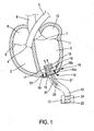
figure 1 est une vue schématique simplifiée d'une pompe cardiaque selon l'invention insérée dans le ventricule gauche d'un coeur, et - La
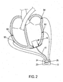
figure 2 est une vue schématique d'une pompe cardiaque selon l'invention équipée d'une pluralité de sondes ou électrodes épicardiques de façon à synchroniser efficacement la pompe cardiaque par rapport à l'activité cardiaque.
- The
figure 1 is a simplified schematic view of a heart pump according to the invention inserted into the left ventricle of a heart, and - The
figure 2 is a schematic view of a heart pump according to the invention equipped with a plurality of epicardial probes or electrodes so as to effectively synchronize the heart pump with respect to cardiac activity.
Bien que l'invention n'y soit pas limitée, on va maintenant décrire une pompe cardiaque implantée dans le ventricule gauche d'un coeur qui est par principe le ventricule systémique. Mais, l'invention peut s'appliquer de la même manière à un ventricule droit lorsque ce dernier est le ventricule systémique.Although the invention is not limited thereto, a heart pump implanted in the left ventricle of a heart which is principle the systemic ventricle. But, the invention can be applied in the same way to a right ventricle when the latter is the systemic ventricle.
Sur les
Sur les
L'oreillette droite 8 alimente le ventricule droit 2 en sang via des valves auriculo-pulmonaires 9. L'oreillette gauche 10 alimente le ventricule gauche 5 en sang via les valves mitrales 11.The
La pompe selon l'invention comporte une unité de gestion 12 reliée par une liaison filaire 13 à un impulseur 14 inséré dans le ventricule gauche 5, au niveau de l'apex, c'est-à-dire à la pointe inférieure du ventricule gauche.The pump according to the invention comprises a
L'impulseur comporte un moteur de préférence de type brushless 15 placé à l'intérieur du ventricule gauche (ou ventricule systémique) de sorte qu'il est facilement accessible à la suite d'une mini-thoracotomie (incision chirurgicale) et ou d'une opération par voie épigastrique en comparaison d'une sternotomie où l'on ouvre complètement le thorax. Ce moteur peut être un moteur à entraînement magnétique équipé d'un rotor sous la forme d'un arbre d'entraînement 16. L'arbre peut être de type «vis sans fin» (« impeller ») permettant d'éjecter le sang depuis le fond du ventricule vers l'aorte 6. Cet arbre peut être aussi un arbre d'entraînement avec une hélice disposée à son extrémité libre. Cette hélice est conformée de telle sorte que la dynamique du fluide sanguin permet d'éjecter le sang vers l'aorte 6.The impeller comprises a brushless type motor preferably placed within the left ventricle (or systemic ventricle) so that it is easily accessible following a mini-thoracotomy (surgical incision) and / or an epigastric operation compared to a sternotomy where the thorax is completely opened. This motor may be a motor with a magnetic drive equipped with a rotor in the form of a
Un carter 18 de forme cylindrique est réalisé tout autour de l'arbre d'entraînement. Ce carter 18 comporte au moins une ouverture, de préférence plusieurs ouvertures en nid d'abeille par exemple, sur sa paroi latérale de façon à permettre l'aspiration de sang provenant de l'oreillette gauche et son évacuation par l'ouverture supérieure du cylindre formant carter 18 par l'action de l'hélice, d'une vis sans fin ou autres ... 17. L'axe de rotation du carter cylindrique 18 est dirigé vers l'orifice aortique. Une telle orientation est avantageusement obtenue lors de la mise en place de l'impulseur par suturage. L'homme du métier comprendra aisément que d'autres types de moteurs miniaturisés biocompatibles peuvent être utilisés pour aspirer et refouler le sang. D'une façon générale les matériaux utilisés pour la mise en oeuvre de la pompe selon l'invention sont biocompatibles et peuvent donc être implantés dans le corps du patient.A
L'impulseur 14 est inséré dans l'apex du coeur et y est maintenu au moyen d'une membrane d'étanchéité et de fixation 19. D'autres types de membranes réalisant parfaitement l'étanchéité peuvent être envisagées. Cette membrane d'étanchéité et de fixation comprend une membrane d'étanchéité 19a associée, c'est-à-dire connectée directement ou non, à un système de fixation 19b, tel une collerette ou tout autre système. Le système de fixation 19b est fixé au moteur et/ou au carter dans l'épaisseur de la paroi du coeur. La membrane d'étanchéité 19a est de préférence suturée sur la paroi externe du coeur de façon à assurer une étanchéité totale entre le ventricule gauche 5 (ou ventricule systémique) et l'extérieur du coeur.The
La membrane d'étanchéité et de fixation peut être de différente forme avec ou sans système de fixation disposé dans l'épaisseur de la paroi du coeur.The sealing and fixing membrane may be of different shapes with or without a fixing system arranged in the thickness of the wall of the core.
La liaison filaire 13 relie l'impulseur 14 à l'unité de gestion 12 qui comporte une alimentation 23 telle qu'une batterie et une unité de commande 24 configurable à distance. La liaison filaire 13 comporte une ligne de commande 21 permettant à l'unité de commande 24 d'envoyer des consignes de commande vers l'impulseur 14, la ligne de commande 21 pouvant être bidirectionnelle. Le câble 20 est un câble alimentation du moteur de l'impulseur 15. Le câble 22 permet de connecter électriquement l'unité de gestion 12 à une sonde d'activité S1 optionnelle insérée dans la paroi du coeur de façon à recueillir l'activité cardiaque du coeur. La sonde d'activité S1 peut être insérée à travers la membrane d'étanchéité et de fixation 19 ou bien au-delà afin de ne pas endommager l'étanchéité. Elle peut en outre être capable de stimuler le ventricule gauche ou droit. Dans ces cas, elle est disposée dans la paroi correspondant au ventricule gauche ou au ventricule droit.The
Avec une telle pompe cardiaque selon l'invention, la liaison entre l'unité de gestion 12 et l'impulseur 14 est obtenue par l'unique liaison 13.With such a heart pump according to the invention, the connection between the
En fonctionnement, l'unité de gestion est configurée de façon à moduler la vitesse de rotation et la durée de fonctionnement du moteur en fonction de lois ou consignes de commande prédéterminées. Lorsqu'on dispose d'une sonde pour recueillir l'activité cardiaque comme par exemple la sonde d'activité S1, l'unité de commande 24 peut être configurée pour asservir le moteur au rythme cardiaque, en temps réel. Cet asservissement permet de synchroniser l'impulseur rotatif à la fréquence cardiaque.In operation, the management unit is configured to modulate the rotation speed and the operating time of the engine according to predetermined laws or control instructions. when has a probe to collect cardiac activity such as S1 activity sensor, the
De préférence, l'unité de gestion est implantée dans la région épigastrique, au sein de l'abdomen du patient. On peut ainsi prévoir que l'unité de commande 24 soit configurable à distance par communication sans fil.Preferably, the management unit is implanted in the epigastric region, within the abdomen of the patient. It can thus be provided that the
Sur la
Les sondes disposées sur le coeur sont de types recueil d'information et stimulateur. Elles permettent d'identifier le début de l'activation électrique et de synchroniser l'impulseur sur l'ouverture des valves. Lorsque les deux ventricules sont soumis chacun à un impulseur, chaque impulseur est synchronisé à l'ouverture des valves correspondantes. Avantageusement, on adapte la fréquence de chaque impulseur de façon à délivrer de préférence un volume d'éjection systolique entre 20 et 35 ml pour chaque cycle cardiaque.The probes arranged on the heart are information gathering and stimulator types. They make it possible to identify the beginning of the electrical activation and to synchronize the impeller on the opening of the valves. When the two ventricles are each subjected to an impeller, each impeller is synchronized at the opening of the corresponding valves. Advantageously, the frequency of each impeller is adapted so as to preferably deliver a volume of systolic ejection between 20 and 35 ml for each cardiac cycle.
Étant donné que la mise en action d'un impulseur dans un ventricule à valve ouverte (durant la systole) augmente la quantité de sang éjectée, la pompe selon l'invention permet d'augmenter le volume d'éjection systolique et par conséquent, le débit sanguin.Since actuation of an impeller in an open valve ventricle (during systole) increases the amount of blood ejected, the pump according to the invention can increase the volume of stroke ejection and therefore the blood flow.
Selon l'exemple illustré sur la
Sur la
En complément notamment de ce qui précède, chacune des sondes S2 et S4 peuvent jouer le rôle de la sonde d'activité S1.In addition to the above, each of the probes S2 and S4 can play the role of the activity probe S1.
Afin de traiter le risque de fibrillations ventriculaires, on prévoit au minimum un patch épicardique ou sonde de défibrillation S5 disposée sur la paroi externe du coeur, l'unité de commande étant configurée pour à la fois détecter une situation de fibrillation et de délivrer des chocs électriques de haute énergie.In order to treat the risk of ventricular fibrillation, at least one epicardial patch or defibrillation probe S5 is provided on the outer wall of the heart, the control unit being configured to both detect a situation of fibrillation and to deliver shocks. high energy electric.
Pour appréhender complètement l'activité cardiaque, on prévoit un capteur d'activité 25 du patient, tel qu'un accéléromètre ou un capteur de pression, disposé par exemple dans l'unité de gestion 12 ou intégré à l'une des sondes précitées. Un tel capteur peut être utile pour un patient atteint d'une insuffisance chronotrope afin de détecter et signaler à l'unité de commande une quelconque accélération de l'activité physique du patient.To fully understand cardiac activity, a patient activity sensor such as an accelerometer or pressure sensor is provided, for example in the
On prévoit également un capteur hémodynamique pour détecter l'état hémodynamique du patient de façon à compléter les informations obtenues sur le rythme cardiaque et commander efficacement l'impulseur. Le capteur hémodynamique peut être un capteur d'accélération endocardique de type PEA ( « Peak Endocardial Acceleration » en langue anglaise ) implanté par exemple ensemble avec l'électrode S2.A hemodynamic sensor is also provided for detecting the hemodynamic status of the patient so as to supplement the information obtained on the heart rate and effectively control the impeller. The hemodynamic sensor may be an endocardial acceleration sensor PEA type ("Peak Endocardial Acceleration" in English) implanted for example together with the electrode S2.
La pompe cardiaque selon l'invention permet donc de réguler le débit sanguin afin d'éviter toute insuffisance cardiaque. En outre, elle peut être implantée dans le coeur par mini-thoracotomie. L'impulseur rotatif peut être inséré au niveau de l'apex (la pointe inférieure) du ventricule gauche et si nécessaire un second impulseur rotatif peut être inséré à l'apex du ventricule droit. Ces deux impulseurs peuvent avantageusement être connectés à une unité de gestion placée dans la région épigastrique. Il s'agit ainsi d'un système fermé sans extériorisation de matériel électrique et d'alimentation.The heart pump according to the invention therefore makes it possible to regulate the blood flow in order to avoid any heart failure. In addition, it can be implanted in the heart by mini-thoracotomy. The rotary impeller may be inserted at the apex (the lower tip) of the left ventricle and if necessary a second rotary impeller may be inserted at the apex of the right ventricle. These two impellers can advantageously be connected to a management unit placed in the epigastric region. It is thus a closed system without externalization of electrical equipment and power supply.
Bien sûr, l'invention n'est pas limitée aux exemples qui viennent d'être décrits et de nombreux aménagements peuvent être apportés à ces exemples sans sortir du cadre de l'invention.Of course, the invention is not limited to the examples that have just been described and many adjustments can be made to these examples without departing from the scope of the invention.
Claims (16)
- Heart pump comprising:- an impeller (14) intended to be inserted in the systemic ventricle (5) of a heart, through the wall of said heart, this impeller being provided with:- a sealing and fixing membrane (19) intended to be partly sutured on the external wall of the heart so as to make the impeller integral with the wall of the heart,- a housing (18) integral with the sealing and fixing membrane (19), this housing being intended to be arranged within the systemic ventricle,- a motor (15) intended to be arranged in the systemic ventricle and/or in the thickness of the ventricle, so as to aspirate and then eject blood, from the bottom, into the systemic ventricle, outside the impeller and in the direction of sigmoid valves (7) of the systemic ventricle, through the housing the sealing membrane being associated with a fixing system fixed, to the motor and/or the housing, within the thickness of the wall of the heart,- a management unit (12) comprising a power supply (23) and a unit (24) for controlling the impeller; and- a connecting wire (13) between the management unit and the impeller.
- Heart pump according to claim 1, characterized in that the motor (15) is what is known as a brushless motor.
- Heart pump according to claim 1 or 2, characterized in that the impeller constitutes a removable unit interchangeable via the wall of the systemic ventricle.
- Heart pump according to any one of the preceding claims, characterized in that the sealing and fixing membrane (19) is fixed so as to ensure a perfect seal and make the impeller integral with the lower part of the heart near the cardiac apex.
- Heart pump according to any one of the preceding claims, characterized in that the motor is of the rotary type and comprises a drive shaft of the rotor type (16) equipped with vanes or an endless screw, said drive shaft being arranged in the housing.
- Heart pump according to any one of the preceding claims, characterized in that the housing (18) is a slender cylinder the side wall of which is of openwork construction so as to allow the flow of aspirated blood, and the axis of revolution of which is in the direction of corresponding sigmoid valves.
- Heart pump according to any one of the preceding claims, characterized in that the management unit (12) is biocompatible so that it can be arranged inside the patient in the epigastric region.
- Heart pump according to any one of the preceding claims, characterized in that the power supply (23) comprises at least one rechargeable battery.
- Heart pump according to any one of the preceding claims, characterized in that it further comprises a sensor, known as an activity sensor (S1), for collecting data on cardiac activity so as to synchronize the operation of the impeller with the electrosystolic cardiac activity; this activity sensor being connected to a wall of the heart.
- Heart pump according to any one of the preceding claims, characterized in that it comprises a sensor for collecting data on cardiac activity and for stimulation, known as a systemic sensor (S2), connected to the wall of the systemic ventricle and able to communicate with the management unit.
- Heart pump according to any one of the preceding claims, characterized in that it further comprises a sensor for collecting data on cardiac activity and for stimulation, known as a non-systemic sensor (S3), connected to the wall of the non-systemic ventricle and able to communicate with the management unit.
- Heart pump according to any one of the preceding claims, characterized in that it further comprises a sensor for collecting data on cardiac activity and for stimulation, known as an atrium sensor (S4), connected to the wall of the systemic atrium and able to communicate with the management unit.
- Heart pump according to any one of the preceding claims, characterized in that it further comprises a sensor for collecting data on cardiac activity, for stimulation and for defibrillation, known as a defibrillation sensor (S5), connected to the wall of the heart and connected by wire to the management unit; the control unit being moreover configured as a defibrillator.
- Heart pump according to any one of claims 1 to 12, characterized in that the management unit (12) is connected wirelessly to a defibrillator.
- Heart pump according to any one of the preceding claims, characterized in that it further comprises a second impeller arranged on the non-systemic ventricle and connected to said management unit.
- Heart pump according to any one of the preceding claims, characterized in that the management unit (12) comprises a wireless transmitter-receiver for transmitting data for monitoring by telecardiology.
Applications Claiming Priority (1)
| Application Number | Priority Date | Filing Date | Title |
|---|---|---|---|
| PCT/FR2011/051830 WO2013014339A1 (en) | 2011-07-28 | 2011-07-28 | Removable heart pump, and method implemented in such a pump |
Publications (2)
| Publication Number | Publication Date |
|---|---|
| EP2736552A1 EP2736552A1 (en) | 2014-06-04 |
| EP2736552B1 true EP2736552B1 (en) | 2015-09-23 |
Family
ID=44653352
Family Applications (1)
| Application Number | Title | Priority Date | Filing Date |
|---|---|---|---|
| EP11757908.6A Active EP2736552B1 (en) | 2011-07-28 | 2011-07-28 | Removable heart pump, and method implemented in such a pump |
Country Status (4)
| Country | Link |
|---|---|
| US (2) | US9731057B2 (en) |
| EP (1) | EP2736552B1 (en) |
| CN (1) | CN103747815A (en) |
| WO (1) | WO2013014339A1 (en) |
Cited By (7)
| Publication number | Priority date | Publication date | Assignee | Title |
|---|---|---|---|---|
| US9968720B2 (en) | 2016-04-11 | 2018-05-15 | CorWave SA | Implantable pump system having an undulating membrane |
| US10166319B2 (en) | 2016-04-11 | 2019-01-01 | CorWave SA | Implantable pump system having a coaxial ventricular cannula |
| US10188779B1 (en) | 2017-11-29 | 2019-01-29 | CorWave SA | Implantable pump system having an undulating membrane with improved hydraulic performance |
| US10799625B2 (en) | 2019-03-15 | 2020-10-13 | CorWave SA | Systems and methods for controlling an implantable blood pump |
| US10933181B2 (en) | 2017-03-31 | 2021-03-02 | CorWave SA | Implantable pump system having a rectangular membrane |
| US11191946B2 (en) | 2020-03-06 | 2021-12-07 | CorWave SA | Implantable blood pumps comprising a linear bearing |
| US11512689B2 (en) | 2017-11-10 | 2022-11-29 | CorWave SA | Undulating-membrane fluid circulator |
Families Citing this family (20)
| Publication number | Priority date | Publication date | Assignee | Title |
|---|---|---|---|---|
| FR2955499B1 (en) * | 2010-01-28 | 2013-06-14 | Fineheart | "AUTONOMOUS CARDIAC PUMP AND METHOD USED IN SUCH A PUMP". |
| US9687385B2 (en) | 2013-03-11 | 2017-06-27 | Avacen, Inc. | Methods and apparatus for therapeutic application of thermal energy including blood viscosity adjustment |
| DE102013106352A1 (en) * | 2013-06-18 | 2014-12-18 | Universität Zu Lübeck | Cardiac support system and cardiac assistive procedure |
| EP3069741A1 (en) * | 2015-03-17 | 2016-09-21 | Berlin Heart GmbH | Heart pump device and method of operating the same |
| AU2017272906B2 (en) * | 2016-06-01 | 2022-04-21 | Northern Research As | Ventricle assist device |
| FR3054450B1 (en) | 2016-07-26 | 2022-12-09 | Fineheart | METHOD FOR MANAGING A HEART PUMP |
| WO2018052482A1 (en) * | 2016-09-19 | 2018-03-22 | Tadashi Motomura | Heart cannula |
| EP3311859B1 (en) * | 2016-10-19 | 2019-12-04 | Abiomed Europe GmbH | Ventricular assist device control |
| EP3366224A1 (en) | 2017-02-23 | 2018-08-29 | Berlin Heart GmbH | Closure device for an opening in the heart of a patient |
| JP7414529B2 (en) | 2017-06-07 | 2024-01-16 | シファメド・ホールディングス・エルエルシー | Intravascular fluid transfer devices, systems, and methods of use |
| JP7319266B2 (en) | 2017-11-13 | 2023-08-01 | シファメド・ホールディングス・エルエルシー | Intravascular fluid transfer devices, systems and methods of use |
| DE102018201030A1 (en) | 2018-01-24 | 2019-07-25 | Kardion Gmbh | Magnetic coupling element with magnetic bearing function |
| FR3077206B1 (en) | 2018-01-29 | 2020-09-18 | Fineheart | VENTRICULAR ASSISTANCE SET WITH STABILIZED HEART PUMP |
| CN117959583A (en) | 2018-02-01 | 2024-05-03 | 施菲姆德控股有限责任公司 | Intravascular blood pump and methods of use and manufacture |
| DE102018211327A1 (en) | 2018-07-10 | 2020-01-16 | Kardion Gmbh | Impeller for an implantable vascular support system |
| EP3996797A4 (en) | 2019-07-12 | 2023-08-02 | Shifamed Holdings, LLC | Intravascular blood pumps and methods of manufacture and use |
| WO2021016372A1 (en) | 2019-07-22 | 2021-01-28 | Shifamed Holdings, Llc | Intravascular blood pumps with struts and methods of use and manufacture |
| US11724089B2 (en) | 2019-09-25 | 2023-08-15 | Shifamed Holdings, Llc | Intravascular blood pump systems and methods of use and control thereof |
| DE102020102474A1 (en) | 2020-01-31 | 2021-08-05 | Kardion Gmbh | Pump for conveying a fluid and method for manufacturing a pump |
| US20230320844A1 (en) | 2022-03-23 | 2023-10-12 | ConneX BioMedical, Inc. | Apparatus and Method for Transcardiac Valve Delivery |
Family Cites Families (21)
| Publication number | Priority date | Publication date | Assignee | Title |
|---|---|---|---|---|
| JPH0636821B2 (en) | 1990-03-08 | 1994-05-18 | 健二 山崎 | Implantable auxiliary artificial heart |
| US5376114A (en) * | 1992-10-30 | 1994-12-27 | Jarvik; Robert | Cannula pumps for temporary cardiac support and methods of their application and use |
| US5957672A (en) | 1993-11-10 | 1999-09-28 | The United States Of America As Represented By The Administrator Of The National Aeronautics And Space Administration | Blood pump bearing system |
| US5507629A (en) | 1994-06-17 | 1996-04-16 | Jarvik; Robert | Artificial hearts with permanent magnet bearings |
| ES2202405T3 (en) * | 1995-09-22 | 2004-04-01 | United States Surgical Corporation | CARDIAC SUPPORT DEVICE. |
| JP2002512821A (en) * | 1998-01-12 | 2002-05-08 | クライン,エンリケ ジェイ. | Improved sealless blood pump |
| US6217541B1 (en) | 1999-01-19 | 2001-04-17 | Kriton Medical, Inc. | Blood pump using cross-flow principles |
| US6245007B1 (en) | 1999-01-28 | 2001-06-12 | Terumo Cardiovascular Systems Corporation | Blood pump |
| DE19904975A1 (en) | 1999-02-06 | 2000-09-14 | Impella Cardiotech Ag | Device for intravascular heart valve surgery |
| US6234772B1 (en) | 1999-04-28 | 2001-05-22 | Kriton Medical, Inc. | Rotary blood pump |
| US7022100B1 (en) | 1999-09-03 | 2006-04-04 | A-Med Systems, Inc. | Guidable intravascular blood pump and related methods |
| US6406422B1 (en) * | 2000-03-02 | 2002-06-18 | Levram Medical Devices, Ltd. | Ventricular-assist method and apparatus |
| CA2374989A1 (en) | 2002-03-08 | 2003-09-08 | Andre Garon | Ventricular assist device comprising a dual inlet hybrid flow blood pump |
| CA2428741A1 (en) | 2003-05-13 | 2004-11-13 | Cardianove Inc. | Dual inlet mixed-flow blood pump |
| ES2421526T3 (en) | 2004-08-13 | 2013-09-03 | Delgado Reynolds M Iii | Apparatus for long-term assistance of a left ventricle to pump blood |
| EP2026856B1 (en) | 2006-05-31 | 2015-08-26 | VADovations, Inc. | Heart assistance device |
| US20080004485A1 (en) * | 2006-06-30 | 2008-01-03 | Moreschi Rafael M | Trans-Septal Heart Assist Devices and Methods of Use |
| CN201020069Y (en) * | 2007-04-29 | 2008-02-13 | 李国荣 | Cardiac apex ventricle wall inner minitype axial flow pump |
| GB0813603D0 (en) * | 2008-07-25 | 2008-09-03 | Cardio Carbon Technology Ltd | Ventricular assist system |
| EP2315609B1 (en) | 2008-08-08 | 2015-12-02 | Calon Cardio Technology Ltd | Heart assist apparatus |
| FR2955499B1 (en) * | 2010-01-28 | 2013-06-14 | Fineheart | "AUTONOMOUS CARDIAC PUMP AND METHOD USED IN SUCH A PUMP". |
-
2011
- 2011-07-28 US US14/235,200 patent/US9731057B2/en active Active
- 2011-07-28 WO PCT/FR2011/051830 patent/WO2013014339A1/en active Application Filing
- 2011-07-28 CN CN201180072653.5A patent/CN103747815A/en active Pending
- 2011-07-28 EP EP11757908.6A patent/EP2736552B1/en active Active
-
2017
- 2017-07-05 US US15/641,535 patent/US10485910B2/en active Active
Cited By (12)
| Publication number | Priority date | Publication date | Assignee | Title |
|---|---|---|---|---|
| US9968720B2 (en) | 2016-04-11 | 2018-05-15 | CorWave SA | Implantable pump system having an undulating membrane |
| US10166319B2 (en) | 2016-04-11 | 2019-01-01 | CorWave SA | Implantable pump system having a coaxial ventricular cannula |
| US11097091B2 (en) | 2016-04-11 | 2021-08-24 | CorWave SA | Implantable pump system having a coaxial ventricular cannula |
| US11298522B2 (en) | 2016-04-11 | 2022-04-12 | CorWave SA | Implantable pump system having an undulating membrane |
| US11712554B2 (en) | 2016-04-11 | 2023-08-01 | CorWave SA | Implantable pump system having a coaxial ventricular cannula |
| US10933181B2 (en) | 2017-03-31 | 2021-03-02 | CorWave SA | Implantable pump system having a rectangular membrane |
| US11623077B2 (en) | 2017-03-31 | 2023-04-11 | CorWave SA | Implantable pump system having a rectangular membrane |
| US11512689B2 (en) | 2017-11-10 | 2022-11-29 | CorWave SA | Undulating-membrane fluid circulator |
| US10188779B1 (en) | 2017-11-29 | 2019-01-29 | CorWave SA | Implantable pump system having an undulating membrane with improved hydraulic performance |
| US11446480B2 (en) | 2017-11-29 | 2022-09-20 | CorWave SA | Implantable pump system having an undulating membrane with improved hydraulic performance |
| US10799625B2 (en) | 2019-03-15 | 2020-10-13 | CorWave SA | Systems and methods for controlling an implantable blood pump |
| US11191946B2 (en) | 2020-03-06 | 2021-12-07 | CorWave SA | Implantable blood pumps comprising a linear bearing |
Also Published As
| Publication number | Publication date |
|---|---|
| CN103747815A (en) | 2014-04-23 |
| US20140207232A1 (en) | 2014-07-24 |
| US20170296723A1 (en) | 2017-10-19 |
| US10485910B2 (en) | 2019-11-26 |
| WO2013014339A1 (en) | 2013-01-31 |
| US9731057B2 (en) | 2017-08-15 |
| EP2736552A1 (en) | 2014-06-04 |
Similar Documents
| Publication | Publication Date | Title |
|---|---|---|
| EP2736552B1 (en) | Removable heart pump, and method implemented in such a pump | |
| EP2528638B1 (en) | Self-contained cardiac pump, and method implemented in such a pump | |
| US11154700B2 (en) | Ventricular assist device and method | |
| KR102282173B1 (en) | Catheter-Based Heart Support System and Method of Implanting Thereof | |
| AU2007201127B2 (en) | System For Preventing Diastolic Heart Failure | |
| JPH0636821B2 (en) | Implantable auxiliary artificial heart | |
| JP2016500534A (en) | Centrifugal pump | |
| AU2021381515A1 (en) | Purgeless mechanical circulatory support system with magnetic drive | |
| EP3490631B1 (en) | Program and control unit for managing a cardiac pump | |
| CA3189345A1 (en) | Unloading blood pump system and the blood pump thereof | |
| EP4059565B1 (en) | Implantable and removable autonomous cardiac capsule with adjustable head and torque limiter | |
| EP3563887A1 (en) | Pump for artificial heart and its drive unit | |
| CA3068172C (en) | Exit pivot for cardiac pump with magnetic coupling | |
| US11484700B1 (en) | Mechanical treatment of heart failure | |
| WO2023118390A1 (en) | A system to treat heart failure with preserved ejection fraction (hfpef) | |
| FR3120797A1 (en) | DIRECT HEART COMPRESSION ASSIST DEVICE | |
| EP4276923A1 (en) | Piezoelectric energy harvester with controlled beam displacement, in particular for power supply of a leadless autonomous cardiac capsule | |
| JP2021532958A (en) | Open electric pump | |
| RO131433B1 (en) | Blood circulation assisting device |
Legal Events
| Date | Code | Title | Description |
|---|---|---|---|
| PUAI | Public reference made under article 153(3) epc to a published international application that has entered the european phase |
Free format text: ORIGINAL CODE: 0009012 |
|
| 17P | Request for examination filed |
Effective date: 20140225 |
|
| AK | Designated contracting states |
Kind code of ref document: A1 Designated state(s): AL AT BE BG CH CY CZ DE DK EE ES FI FR GB GR HR HU IE IS IT LI LT LU LV MC MK MT NL NO PL PT RO RS SE SI SK SM TR |
|
| DAX | Request for extension of the european patent (deleted) | ||
| GRAP | Despatch of communication of intention to grant a patent |
Free format text: ORIGINAL CODE: EPIDOSNIGR1 |
|
| INTG | Intention to grant announced |
Effective date: 20150420 |
|
| GRAS | Grant fee paid |
Free format text: ORIGINAL CODE: EPIDOSNIGR3 |
|
| GRAA | (expected) grant |
Free format text: ORIGINAL CODE: 0009210 |
|
| RAP1 | Party data changed (applicant data changed or rights of an application transferred) |
Owner name: FINEHEART |
|
| AK | Designated contracting states |
Kind code of ref document: B1 Designated state(s): AL AT BE BG CH CY CZ DE DK EE ES FI FR GB GR HR HU IE IS IT LI LT LU LV MC MK MT NL NO PL PT RO RS SE SI SK SM TR |
|
| REG | Reference to a national code |
Ref country code: GB Ref legal event code: FG4D Free format text: NOT ENGLISH |
|
| REG | Reference to a national code |
Ref country code: CH Ref legal event code: EP |
|
| REG | Reference to a national code |
Ref country code: AT Ref legal event code: REF Ref document number: 750874 Country of ref document: AT Kind code of ref document: T Effective date: 20151015 |
|
| REG | Reference to a national code |
Ref country code: IE Ref legal event code: FG4D Free format text: LANGUAGE OF EP DOCUMENT: FRENCH |
|
| REG | Reference to a national code |
Ref country code: DE Ref legal event code: R096 Ref document number: 602011020027 Country of ref document: DE |
|
| REG | Reference to a national code |
Ref country code: NL Ref legal event code: MP Effective date: 20150923 |
|
| PG25 | Lapsed in a contracting state [announced via postgrant information from national office to epo] |
Ref country code: LT Free format text: LAPSE BECAUSE OF FAILURE TO SUBMIT A TRANSLATION OF THE DESCRIPTION OR TO PAY THE FEE WITHIN THE PRESCRIBED TIME-LIMIT Effective date: 20150923 Ref country code: LV Free format text: LAPSE BECAUSE OF FAILURE TO SUBMIT A TRANSLATION OF THE DESCRIPTION OR TO PAY THE FEE WITHIN THE PRESCRIBED TIME-LIMIT Effective date: 20150923 Ref country code: FI Free format text: LAPSE BECAUSE OF FAILURE TO SUBMIT A TRANSLATION OF THE DESCRIPTION OR TO PAY THE FEE WITHIN THE PRESCRIBED TIME-LIMIT Effective date: 20150923 Ref country code: GR Free format text: LAPSE BECAUSE OF FAILURE TO SUBMIT A TRANSLATION OF THE DESCRIPTION OR TO PAY THE FEE WITHIN THE PRESCRIBED TIME-LIMIT Effective date: 20151224 Ref country code: NO Free format text: LAPSE BECAUSE OF FAILURE TO SUBMIT A TRANSLATION OF THE DESCRIPTION OR TO PAY THE FEE WITHIN THE PRESCRIBED TIME-LIMIT Effective date: 20151223 |
|
| REG | Reference to a national code |
Ref country code: LT Ref legal event code: MG4D |
|
| REG | Reference to a national code |
Ref country code: AT Ref legal event code: MK05 Ref document number: 750874 Country of ref document: AT Kind code of ref document: T Effective date: 20150923 |
|
| PG25 | Lapsed in a contracting state [announced via postgrant information from national office to epo] |
Ref country code: SE Free format text: LAPSE BECAUSE OF FAILURE TO SUBMIT A TRANSLATION OF THE DESCRIPTION OR TO PAY THE FEE WITHIN THE PRESCRIBED TIME-LIMIT Effective date: 20150923 Ref country code: HR Free format text: LAPSE BECAUSE OF FAILURE TO SUBMIT A TRANSLATION OF THE DESCRIPTION OR TO PAY THE FEE WITHIN THE PRESCRIBED TIME-LIMIT Effective date: 20150923 Ref country code: RS Free format text: LAPSE BECAUSE OF FAILURE TO SUBMIT A TRANSLATION OF THE DESCRIPTION OR TO PAY THE FEE WITHIN THE PRESCRIBED TIME-LIMIT Effective date: 20150923 |
|
| PG25 | Lapsed in a contracting state [announced via postgrant information from national office to epo] |
Ref country code: NL Free format text: LAPSE BECAUSE OF FAILURE TO SUBMIT A TRANSLATION OF THE DESCRIPTION OR TO PAY THE FEE WITHIN THE PRESCRIBED TIME-LIMIT Effective date: 20150923 |
|
| PG25 | Lapsed in a contracting state [announced via postgrant information from national office to epo] |
Ref country code: IS Free format text: LAPSE BECAUSE OF FAILURE TO SUBMIT A TRANSLATION OF THE DESCRIPTION OR TO PAY THE FEE WITHIN THE PRESCRIBED TIME-LIMIT Effective date: 20160123 Ref country code: SK Free format text: LAPSE BECAUSE OF FAILURE TO SUBMIT A TRANSLATION OF THE DESCRIPTION OR TO PAY THE FEE WITHIN THE PRESCRIBED TIME-LIMIT Effective date: 20150923 Ref country code: ES Free format text: LAPSE BECAUSE OF FAILURE TO SUBMIT A TRANSLATION OF THE DESCRIPTION OR TO PAY THE FEE WITHIN THE PRESCRIBED TIME-LIMIT Effective date: 20150923 Ref country code: CZ Free format text: LAPSE BECAUSE OF FAILURE TO SUBMIT A TRANSLATION OF THE DESCRIPTION OR TO PAY THE FEE WITHIN THE PRESCRIBED TIME-LIMIT Effective date: 20150923 Ref country code: IT Free format text: LAPSE BECAUSE OF FAILURE TO SUBMIT A TRANSLATION OF THE DESCRIPTION OR TO PAY THE FEE WITHIN THE PRESCRIBED TIME-LIMIT Effective date: 20150923 Ref country code: EE Free format text: LAPSE BECAUSE OF FAILURE TO SUBMIT A TRANSLATION OF THE DESCRIPTION OR TO PAY THE FEE WITHIN THE PRESCRIBED TIME-LIMIT Effective date: 20150923 |
|
| PG25 | Lapsed in a contracting state [announced via postgrant information from national office to epo] |
Ref country code: RO Free format text: LAPSE BECAUSE OF FAILURE TO SUBMIT A TRANSLATION OF THE DESCRIPTION OR TO PAY THE FEE WITHIN THE PRESCRIBED TIME-LIMIT Effective date: 20150923 Ref country code: PL Free format text: LAPSE BECAUSE OF FAILURE TO SUBMIT A TRANSLATION OF THE DESCRIPTION OR TO PAY THE FEE WITHIN THE PRESCRIBED TIME-LIMIT Effective date: 20150923 Ref country code: AT Free format text: LAPSE BECAUSE OF FAILURE TO SUBMIT A TRANSLATION OF THE DESCRIPTION OR TO PAY THE FEE WITHIN THE PRESCRIBED TIME-LIMIT Effective date: 20150923 Ref country code: PT Free format text: LAPSE BECAUSE OF FAILURE TO SUBMIT A TRANSLATION OF THE DESCRIPTION OR TO PAY THE FEE WITHIN THE PRESCRIBED TIME-LIMIT Effective date: 20160125 |
|
| REG | Reference to a national code |
Ref country code: DE Ref legal event code: R097 Ref document number: 602011020027 Country of ref document: DE |
|
| REG | Reference to a national code |
Ref country code: FR Ref legal event code: PLFP Year of fee payment: 6 |
|
| PGFP | Annual fee paid to national office [announced via postgrant information from national office to epo] |
Ref country code: IE Payment date: 20160622 Year of fee payment: 6 |
|
| PLBE | No opposition filed within time limit |
Free format text: ORIGINAL CODE: 0009261 |
|
| STAA | Information on the status of an ep patent application or granted ep patent |
Free format text: STATUS: NO OPPOSITION FILED WITHIN TIME LIMIT |
|
| 26N | No opposition filed |
Effective date: 20160624 |
|
| PG25 | Lapsed in a contracting state [announced via postgrant information from national office to epo] |
Ref country code: DK Free format text: LAPSE BECAUSE OF FAILURE TO SUBMIT A TRANSLATION OF THE DESCRIPTION OR TO PAY THE FEE WITHIN THE PRESCRIBED TIME-LIMIT Effective date: 20150923 |
|
| PG25 | Lapsed in a contracting state [announced via postgrant information from national office to epo] |
Ref country code: SI Free format text: LAPSE BECAUSE OF FAILURE TO SUBMIT A TRANSLATION OF THE DESCRIPTION OR TO PAY THE FEE WITHIN THE PRESCRIBED TIME-LIMIT Effective date: 20150923 |
|
| PG25 | Lapsed in a contracting state [announced via postgrant information from national office to epo] |
Ref country code: BE Free format text: LAPSE BECAUSE OF NON-PAYMENT OF DUE FEES Effective date: 20160731 |
|
| REG | Reference to a national code |
Ref country code: CH Ref legal event code: PL |
|
| PG25 | Lapsed in a contracting state [announced via postgrant information from national office to epo] |
Ref country code: MC Free format text: LAPSE BECAUSE OF FAILURE TO SUBMIT A TRANSLATION OF THE DESCRIPTION OR TO PAY THE FEE WITHIN THE PRESCRIBED TIME-LIMIT Effective date: 20150923 |
|
| PG25 | Lapsed in a contracting state [announced via postgrant information from national office to epo] |
Ref country code: LI Free format text: LAPSE BECAUSE OF NON-PAYMENT OF DUE FEES Effective date: 20160731 Ref country code: CH Free format text: LAPSE BECAUSE OF NON-PAYMENT OF DUE FEES Effective date: 20160731 |
|
| REG | Reference to a national code |
Ref country code: FR Ref legal event code: PLFP Year of fee payment: 7 |
|
| PG25 | Lapsed in a contracting state [announced via postgrant information from national office to epo] |
Ref country code: LU Free format text: LAPSE BECAUSE OF NON-PAYMENT OF DUE FEES Effective date: 20160728 |
|
| REG | Reference to a national code |
Ref country code: IE Ref legal event code: MM4A |
|
| PG25 | Lapsed in a contracting state [announced via postgrant information from national office to epo] |
Ref country code: IE Free format text: LAPSE BECAUSE OF NON-PAYMENT OF DUE FEES Effective date: 20170728 |
|
| PG25 | Lapsed in a contracting state [announced via postgrant information from national office to epo] |
Ref country code: SM Free format text: LAPSE BECAUSE OF FAILURE TO SUBMIT A TRANSLATION OF THE DESCRIPTION OR TO PAY THE FEE WITHIN THE PRESCRIBED TIME-LIMIT Effective date: 20150923 Ref country code: HU Free format text: LAPSE BECAUSE OF FAILURE TO SUBMIT A TRANSLATION OF THE DESCRIPTION OR TO PAY THE FEE WITHIN THE PRESCRIBED TIME-LIMIT; INVALID AB INITIO Effective date: 20110728 Ref country code: CY Free format text: LAPSE BECAUSE OF FAILURE TO SUBMIT A TRANSLATION OF THE DESCRIPTION OR TO PAY THE FEE WITHIN THE PRESCRIBED TIME-LIMIT Effective date: 20150923 |
|
| PG25 | Lapsed in a contracting state [announced via postgrant information from national office to epo] |
Ref country code: MK Free format text: LAPSE BECAUSE OF FAILURE TO SUBMIT A TRANSLATION OF THE DESCRIPTION OR TO PAY THE FEE WITHIN THE PRESCRIBED TIME-LIMIT Effective date: 20150923 Ref country code: MT Free format text: LAPSE BECAUSE OF FAILURE TO SUBMIT A TRANSLATION OF THE DESCRIPTION OR TO PAY THE FEE WITHIN THE PRESCRIBED TIME-LIMIT Effective date: 20150923 |
|
| REG | Reference to a national code |
Ref country code: FR Ref legal event code: PLFP Year of fee payment: 8 |
|
| PG25 | Lapsed in a contracting state [announced via postgrant information from national office to epo] |
Ref country code: BG Free format text: LAPSE BECAUSE OF FAILURE TO SUBMIT A TRANSLATION OF THE DESCRIPTION OR TO PAY THE FEE WITHIN THE PRESCRIBED TIME-LIMIT Effective date: 20150923 |
|
| PG25 | Lapsed in a contracting state [announced via postgrant information from national office to epo] |
Ref country code: AL Free format text: LAPSE BECAUSE OF FAILURE TO SUBMIT A TRANSLATION OF THE DESCRIPTION OR TO PAY THE FEE WITHIN THE PRESCRIBED TIME-LIMIT Effective date: 20150923 Ref country code: TR Free format text: LAPSE BECAUSE OF FAILURE TO SUBMIT A TRANSLATION OF THE DESCRIPTION OR TO PAY THE FEE WITHIN THE PRESCRIBED TIME-LIMIT Effective date: 20150923 |
|
| REG | Reference to a national code |
Ref country code: DE Ref legal event code: R079 Ref document number: 602011020027 Country of ref document: DE Free format text: PREVIOUS MAIN CLASS: A61M0001100000 Ipc: A61M0060000000 |
|
| P01 | Opt-out of the competence of the unified patent court (upc) registered |
Effective date: 20230519 |
|
| PGFP | Annual fee paid to national office [announced via postgrant information from national office to epo] |
Ref country code: GB Payment date: 20230728 Year of fee payment: 13 |
|
| PGFP | Annual fee paid to national office [announced via postgrant information from national office to epo] |
Ref country code: FR Payment date: 20230728 Year of fee payment: 13 Ref country code: DE Payment date: 20230728 Year of fee payment: 13 |