EP2736100B1 - Electronic unit with temperature measuring device for a battery system - Google Patents
Electronic unit with temperature measuring device for a battery system Download PDFInfo
- Publication number
- EP2736100B1 EP2736100B1 EP12193807.0A EP12193807A EP2736100B1 EP 2736100 B1 EP2736100 B1 EP 2736100B1 EP 12193807 A EP12193807 A EP 12193807A EP 2736100 B1 EP2736100 B1 EP 2736100B1
- Authority
- EP
- European Patent Office
- Prior art keywords
- electronic unit
- measuring device
- temperature measuring
- battery
- temperature
- Prior art date
- Legal status (The legal status is an assumption and is not a legal conclusion. Google has not performed a legal analysis and makes no representation as to the accuracy of the status listed.)
- Active
Links
- 238000005259 measurement Methods 0.000 claims description 18
- 239000012212 insulator Substances 0.000 claims description 17
- 238000012544 monitoring process Methods 0.000 claims description 12
- 230000005855 radiation Effects 0.000 claims description 6
- 238000010079 rubber tapping Methods 0.000 claims description 3
- 230000003287 optical effect Effects 0.000 description 5
- 238000013461 design Methods 0.000 description 3
- 238000011156 evaluation Methods 0.000 description 3
- 238000009434 installation Methods 0.000 description 3
- 239000000463 material Substances 0.000 description 3
- 238000005496 tempering Methods 0.000 description 3
- 238000012546 transfer Methods 0.000 description 3
- 230000003750 conditioning effect Effects 0.000 description 2
- 238000001816 cooling Methods 0.000 description 2
- 238000001514 detection method Methods 0.000 description 2
- 238000009826 distribution Methods 0.000 description 2
- 238000010438 heat treatment Methods 0.000 description 2
- 238000000034 method Methods 0.000 description 2
- 238000013021 overheating Methods 0.000 description 2
- 238000001931 thermography Methods 0.000 description 2
- 238000012935 Averaging Methods 0.000 description 1
- RYGMFSIKBFXOCR-UHFFFAOYSA-N Copper Chemical compound [Cu] RYGMFSIKBFXOCR-UHFFFAOYSA-N 0.000 description 1
- 239000004743 Polypropylene Substances 0.000 description 1
- 239000002313 adhesive film Substances 0.000 description 1
- 230000032683 aging Effects 0.000 description 1
- 230000005540 biological transmission Effects 0.000 description 1
- 239000004020 conductor Substances 0.000 description 1
- 230000001276 controlling effect Effects 0.000 description 1
- 229910052802 copper Inorganic materials 0.000 description 1
- 239000010949 copper Substances 0.000 description 1
- 230000001419 dependent effect Effects 0.000 description 1
- 230000010259 detection of temperature stimulus Effects 0.000 description 1
- 238000011161 development Methods 0.000 description 1
- 230000018109 developmental process Effects 0.000 description 1
- 239000007772 electrode material Substances 0.000 description 1
- 239000011521 glass Substances 0.000 description 1
- 230000002631 hypothermal effect Effects 0.000 description 1
- 238000011835 investigation Methods 0.000 description 1
- 238000003475 lamination Methods 0.000 description 1
- 230000007257 malfunction Effects 0.000 description 1
- 238000004519 manufacturing process Methods 0.000 description 1
- 238000003801 milling Methods 0.000 description 1
- 239000003973 paint Substances 0.000 description 1
- -1 polypropylene Polymers 0.000 description 1
- 229920001155 polypropylene Polymers 0.000 description 1
- 238000004080 punching Methods 0.000 description 1
- 230000001105 regulatory effect Effects 0.000 description 1
- 238000012360 testing method Methods 0.000 description 1
Images


Classifications
-
- G—PHYSICS
- G01—MEASURING; TESTING
- G01J—MEASUREMENT OF INTENSITY, VELOCITY, SPECTRAL CONTENT, POLARISATION, PHASE OR PULSE CHARACTERISTICS OF INFRARED, VISIBLE OR ULTRAVIOLET LIGHT; COLORIMETRY; RADIATION PYROMETRY
- G01J5/00—Radiation pyrometry, e.g. infrared or optical thermometry
- G01J5/02—Constructional details
- G01J5/028—Constructional details using a charging unit or battery
-
- H—ELECTRICITY
- H01—ELECTRIC ELEMENTS
- H01M—PROCESSES OR MEANS, e.g. BATTERIES, FOR THE DIRECT CONVERSION OF CHEMICAL ENERGY INTO ELECTRICAL ENERGY
- H01M10/00—Secondary cells; Manufacture thereof
- H01M10/42—Methods or arrangements for servicing or maintenance of secondary cells or secondary half-cells
- H01M10/48—Accumulators combined with arrangements for measuring, testing or indicating the condition of cells, e.g. the level or density of the electrolyte
- H01M10/482—Accumulators combined with arrangements for measuring, testing or indicating the condition of cells, e.g. the level or density of the electrolyte for several batteries or cells simultaneously or sequentially
-
- H—ELECTRICITY
- H01—ELECTRIC ELEMENTS
- H01M—PROCESSES OR MEANS, e.g. BATTERIES, FOR THE DIRECT CONVERSION OF CHEMICAL ENERGY INTO ELECTRICAL ENERGY
- H01M10/00—Secondary cells; Manufacture thereof
- H01M10/42—Methods or arrangements for servicing or maintenance of secondary cells or secondary half-cells
- H01M10/48—Accumulators combined with arrangements for measuring, testing or indicating the condition of cells, e.g. the level or density of the electrolyte
- H01M10/486—Accumulators combined with arrangements for measuring, testing or indicating the condition of cells, e.g. the level or density of the electrolyte for measuring temperature
-
- H—ELECTRICITY
- H01—ELECTRIC ELEMENTS
- H01M—PROCESSES OR MEANS, e.g. BATTERIES, FOR THE DIRECT CONVERSION OF CHEMICAL ENERGY INTO ELECTRICAL ENERGY
- H01M50/00—Constructional details or processes of manufacture of the non-active parts of electrochemical cells other than fuel cells, e.g. hybrid cells
- H01M50/50—Current conducting connections for cells or batteries
- H01M50/572—Means for preventing undesired use or discharge
- H01M50/574—Devices or arrangements for the interruption of current
- H01M50/581—Devices or arrangements for the interruption of current in response to temperature
-
- H—ELECTRICITY
- H01—ELECTRIC ELEMENTS
- H01M—PROCESSES OR MEANS, e.g. BATTERIES, FOR THE DIRECT CONVERSION OF CHEMICAL ENERGY INTO ELECTRICAL ENERGY
- H01M10/00—Secondary cells; Manufacture thereof
- H01M10/42—Methods or arrangements for servicing or maintenance of secondary cells or secondary half-cells
- H01M10/425—Structural combination with electronic components, e.g. electronic circuits integrated to the outside of the casing
- H01M2010/4271—Battery management systems including electronic circuits, e.g. control of current or voltage to keep battery in healthy state, cell balancing
-
- H—ELECTRICITY
- H01—ELECTRIC ELEMENTS
- H01M—PROCESSES OR MEANS, e.g. BATTERIES, FOR THE DIRECT CONVERSION OF CHEMICAL ENERGY INTO ELECTRICAL ENERGY
- H01M2200/00—Safety devices for primary or secondary batteries
- H01M2200/10—Temperature sensitive devices
-
- Y—GENERAL TAGGING OF NEW TECHNOLOGICAL DEVELOPMENTS; GENERAL TAGGING OF CROSS-SECTIONAL TECHNOLOGIES SPANNING OVER SEVERAL SECTIONS OF THE IPC; TECHNICAL SUBJECTS COVERED BY FORMER USPC CROSS-REFERENCE ART COLLECTIONS [XRACs] AND DIGESTS
- Y02—TECHNOLOGIES OR APPLICATIONS FOR MITIGATION OR ADAPTATION AGAINST CLIMATE CHANGE
- Y02E—REDUCTION OF GREENHOUSE GAS [GHG] EMISSIONS, RELATED TO ENERGY GENERATION, TRANSMISSION OR DISTRIBUTION
- Y02E60/00—Enabling technologies; Technologies with a potential or indirect contribution to GHG emissions mitigation
- Y02E60/10—Energy storage using batteries
Definitions
- the present invention relates to an electronic unit with temperature measuring device for a battery system.
- the invention further relates to a battery system comprising a plurality of battery cells and at least one electronic unit with a temperature measuring device.
- the temperature of the battery cells has a major influence on the performance, reliability and aging of a battery.
- By detecting the temperature of individual battery cells can be counteracted by means of cooling / heating means exceeding or falling below an upper and lower target limit of the temperature for the operation of the battery cells.
- diodes can be used as diodes.
- transistors which are connected as diodes.
- Most of the sensor elements are designed as NTC resistors or PTC resistors.
- the DE 10 2005 058 315 A1 discloses a measuring method that locally detects and determines the battery or battery surface at various spaced apart measuring points with an infrared sensor or a thermal imaging camera.
- different scanning paths or scan curves relative to the measuring battery or battery surface can be traversed with the infrared sensor, or it can be electronically selected from a thermal image recording individual measuring points according to a predetermined pattern.
- the more extensive the number of measuring points and the more complex the scanning paths or measuring point patterns the more accurate the statements about the temperature distribution and the more accurate statements on the battery or battery status become possible.
- the infrared sensor can be used in the DE 10 2005 058 315 A1
- the battery or battery surface can be scanned with a point-measuring infrared sensor by either the infrared sensor or the base of the battery measuring station is driven by a motor and thus movable, so that different scanning paths can be traversed by means of the motor.
- it may additionally be provided to pass through the measuring point grid several times with one scanning operation in order to better filter out statistical measured value deviations of a single measurement or at least to be able to compensate by averaging.
- the in the DE 10 2005 058 315 A1 described devices and the disclosed method are suitable for investigations on test benches and in laboratories.
- the reliable non-contact monitoring of the temperature of several battery cells of a battery module or a battery system is possible due to the installation position and the cramped space, for example in a motor vehicle in the manner described in the prior art only with great technical effort and high costs.
- thermocouples are contact-connected to the surface of the batteries.
- the EP 1 667 307 A1 describes a device for protection against excessive operating temperatures of mobile phones, the battery is mechanically coupled to a control system on a housing board in card form and an infrared thermal sensor with the battery is in non-contact measuring contact. It is therefore an object of the invention to improve temperature measuring devices of the type mentioned in this regard and in particular to provide a non-contact electronic unit with temperature measuring device that is easy to manufacture and permanently associated with a battery module of a battery system, and a continuous and reliable measurement of the temperature of multiple battery cells a battery system, in particular in a motor vehicle during operation allows.
- an electronic unit with temperature measuring device for a battery system wherein the battery system comprises a plurality of battery cells and at least one arranged in a battery housing of the battery system electronics unit with temperature measuring device, said on a circuit board of the electronic unit with temperature measuring device and the printed circuit board of the electronic unit with temperature measuring device operatively connected at least two infrared temperature sensors are arranged, wherein the infrared temperature sensors mechanically decoupled from the battery cells are arranged and aligned so that by an infrared temperature sensor, the temperature of a predetermined measuring range can be detected on a surface of the battery system, wherein an effective measuring field ( 35) is adjustable by the distance between the temperature sensors (32) and the monitored surface of the battery system.
- the predetermined measuring ranges are advantageously arranged at a distance from one another on the surface of the battery system such that they preferably do not overlap or overlap one another.
- the advantage of this electronic unit with temperature measuring device is that by using a plurality of infrared temperature sensors, the temperature of subregions of a battery system, in particular of individual battery cells and also of subregions of individual battery cells can be monitored simultaneously and continuously.
- the non-contact measurement of the surface temperature via infrared radiation enables the mechanical decoupling of the heavy battery cells from the sensitive sensor elements. Due to the precise and precise arrangement of the infrared temperature sensors, for example, on a printed circuit board of an electronic unit with temperature measuring device, a simple assembly of both the electronic unit and the battery system is given. In particular, the assembly and adjustment of the infrared temperature sensors having electronic unit with temperature measuring device on a multiple battery cell battery module is simplified compared to batteries with conventional temperature measuring devices.
- the battery module is a structural subunit of a battery system.
- a battery module comprises a plurality of mechanically and electrically interconnected battery cells and usually also an electronics unit and / or parts of a tempering system.
- a battery system typically includes multiple battery modules.
- the predetermined by the design of the infrared temperature sensor field of view of the sensor determines the orientation of the sensor and the distance to the measurement object, an "effective measuring field" on the surface of the measuring object, eg the battery cell of a battery system. At a correspondingly small distance, this "effective measuring field" is small enough to be able to detect subregions of a battery cell as predetermined measuring ranges.
- the measuring ranges are determined by suitable positioning and / or orientation of the infrared temperature sensors on or in the electronics unit with temperature measuring device predetermined.
- the object is also achieved by a battery system comprising a plurality of battery cells and at least one electronic unit with a temperature measuring device.
- the invention made possible by the detection of temperatures at selected portions of a plurality of battery cells allows better control of a tempering of the battery system and thus serves to increase the security against overheating of individual battery cells both when charging and while driving.
- the infrared temperature sensors used may include optical windows or other optical components, such as refractive or diffractive lenses.
- optical windows or other optical components such as refractive or diffractive lenses.
- additional optical components is preferably dispensed with.
- a distance of less than 50 millimeters between infrared temperature sensors and the respective predetermined measuring range on the surface of the battery system is suitable.
- this distance is less than 20 millimeters and more preferably less than 10 millimeters.
- the diameter of the "effective measuring field" may result, even without the use of additional optical components, a predetermined measuring range on a surface having a diameter of, for example, less than about 10 millimeters having.
- the infrared temperature sensors are arranged thermally decoupled from the printed circuit board of the electronic unit with temperature measuring device.
- Thermally decoupled in this patent is to be understood that measures are taken to reduce the heat transfer.
- the copper lamination of the printed circuit board in the vicinity of the infrared temperature sensor is largely removed and electrical lines (printed conductors) are designed with the smallest possible cross-section.
- electrical lines printed conductors
- a substantial exemption of the mounting range of the infrared temperature sensor on the circuit board by milling or punching is conducive.
- rapid temperature fluctuations of the infrared temperature sensors which are not caused by thermal radiation of the measurement objects (for example, caused by thermal conduction of heat sources on the circuit board of the electronics unit with temperature measuring device caused temperature fluctuations) or avoided.
- thermoelectric unit with a temperature measuring device in which the infrared temperature sensors are partially thermally decoupled from the surface of the battery cells by a first insulator arranged between the battery cells and a side facing the battery cells facing the electronic unit with temperature measuring device.
- the first insulator (one or more parts) is designed so that areas of the printed circuit board of the electronic unit with temperature measuring device in the immediate vicinity of the infrared temperature sensors protected against heat input.
- the active surface of the infrared temperature sensors is left out.
- the first insulator for example, openings.
- the openings in the first insulator are particularly preferably designed and arranged such that, on the one hand, they are as small as possible, but on the other hand, they do not impair the field of view and also the "effective measuring field" of the infrared temperature sensors.
- the first isolator prevents or reduces the transmission of rapid temperature fluctuations from other areas of the battery system, depending on the installation position in particular by convective heat transfer or by heat radiation, on portions of the temperature measuring device.
- the electronic unit with temperature measuring device is thermally decoupled from further components of the battery system by a second insulator arranged on the side of the electronics unit facing away from the battery cells with temperature measuring device.
- the first and second insulator can also be designed as a structural unit and thus enclose the entire electronic unit with temperature measuring device or parts thereof.
- the above-mentioned first and second insulators are thermal insulators. Suitable materials and further embodiments of said insulators, as well as further measures for the thermal decoupling of the infrared temperature sensors from their immediate surroundings, are known to the person skilled in the art.
- the electronic unit according to the invention with temperature measuring device in which the predetermined measuring range of the surface of the battery cell comprises a predetermined breaking point of the battery cell.
- the predetermined breaking point In the region of the predetermined breaking point, the wall of the battery cell on a smaller wall thickness, characterized in the case of malfunction of the battery cell, the surface of the battery cell is heated faster in the region of the predetermined breaking point and thus allows the early detection of errors.
- a predetermined measuring range of the surface of the battery cell is also located near a cell pole of the battery cell.
- a predetermined measuring range of the surface of the battery cell is also located near a cell pole of the battery cell.
- the predetermined measuring range lies on a cell connector arranged between two battery cells. This arrangement allows the simultaneous monitoring of two adjacent cell poles and thus battery cells with only one infrared temperature sensor.
- An arrangement in which the effective measuring field of an infrared temperature sensor simultaneously detects adjacent areas of the surfaces of two juxtaposed battery cells is advantageous and allows the simultaneous monitoring of two battery cells with only one infrared temperature sensor.
- the predetermined measuring range on a surface of the battery system has a means for increasing the emission coefficient. Should the surface of the predetermined Measuring range itself have no good emission properties (eg the smooth metallic surface of the cell connector) so the surface can be changed by applying a suitable layer (black matte paint, adhesive film, etc.) locally suitable.
- a suitable layer black matte paint, adhesive film, etc.
- At least one battery cell has a window in the region of the effective measuring field (35) of the infrared temperature sensor.
- Suitable materials for such a window are, for example, polypropylene and certain types of glass. Other suitable materials are known to the person skilled in the art.
- the infrared temperature sensor is a radiation thermopile or a bolometer. Both sensor types are particularly well suited for measuring low temperatures (-50 ° C to 100 ° C), can be made compact and can be easily installed on printed circuit boards.
- additional temperature sensors infrared temperature sensors and / or other types of temperature sensors
- additional temperature data for example, as reference data, from areas of the battery module or Battery system are detected, which are not accessible to the fixed on the PCB infrared temperature sensors.
- the electronic unit with temperature measuring device is a cell monitoring unit, wherein the cell monitoring unit measures the voltage at cell poles and / or cell connectors via voltage tapping elements.
- the electronic unit with temperature measuring device as cell monitoring unit usually houses a microprocessor which is set up for monitoring and usually also for regulating the cell voltages.
- the electronic unit with temperature measuring device is a connection board which can be connected to a cell monitoring unit.
- the interconnect board accommodates only the infrared temperature sensors and the required electrical leads which lead from the contacts of the infrared temperature sensors to a terminal for, for example, another electronic unit housing a microprocessor.
- the above-mentioned measures and devices according to the invention increase the operational safety of a battery system.
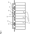
- a battery module comprising a number of battery cells 13 is shown.
- the cell poles 14 of adjacent battery cells 13 are interconnected by cell connectors 15 such that a series connection of the battery cells 13 results.
- An electronic unit 30 constructed on a printed circuit board has a number of infrared temperature sensors 32.
- the infrared temperature sensors 32 are arranged and aligned on the printed circuit board of the electronic unit 30 so that an effective measuring field 35 predetermined areas of the surface detected by battery cells.
- predetermined portions of the surface of each two adjacent battery cells are detected and monitored with only one infrared temperature sensor.
- the effective measuring field 35 of the infrared temperature sensors 32 is shown schematically in the side view as a cone. The opening angle of this field of view is determined by the design of the infrared temperature sensor and possibly contained therein optical devices. Given a field of view, the effective measuring field 35 can be adjusted by the distance between the temperature sensor and the surface to be monitored.
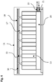
- FIG. 2 are the battery module and the electronic unit according to the invention with temperature measuring device Fig. 1 shown in plan view.
- the electronic unit 30 comprises, in addition to the three infrared temperature sensors 32 also shown, devices not shown for measuring the voltage levels of battery cells 13.
- the voltage levels of the battery cells 13 are conducted via voltage tapping elements 31 from the cell connectors 15 to the electronic unit 30.
- the effective measuring fields of the infrared temperature sensors 32 are circular and shown as broken lines.
- Each temperature sensor is assigned a signal conditioning unit which converts the measurement signal received by the temperature sensor into a measurement voltage or preferably into a digital measurement signal.
- the processed by the signal conditioning units measurement signals are fed to the evaluation of a microprocessor or microcontroller.
- FIG. 3 is a further exemplary embodiment of an electronic unit according to the invention with temperature measuring device shown.
- the illustrated electronic unit 30 has herein for each of the battery cells 13 has a separate infrared temperature sensor 32 assigned to it.
- FIG. 4 shows a battery system in a battery housing 11 with an arrangement for controlling the temperature of the battery cells 13.
- a temperature control 20 is supplied via an inlet opening 21 temperature control and returned via an outlet opening 22 in an external circuit for cooling / heating.
- the battery cells 13 are protected against overheating as well as against hypothermia.
- the tempering system 20 generates an optimal temperature range for operating the battery cells 13 in accordance with the measured data of the (infrared) temperature sensors.
- the electronic unit 30 together with infrared temperature sensors 32 is protected by a first insulator 17 and a second insulator 18 against thermal influences from other areas of the battery system.
- the first insulator 17 has small openings which are designed such that they do not impair the field of view and thus the effective measuring field 35 of the infrared temperature sensors 32.
- Microprocessors or microcontrollers are in the schematic representations of FIGS. 1 to 4 not shown. They can be arranged directly on the electronic units 30, or also be connected via analog and / or digital lines, in particular serial bus systems with higher-level electronic devices, for example a battery monitoring unit (BMU).
- BMU battery monitoring unit
Landscapes
- Chemical & Material Sciences (AREA)
- Chemical Kinetics & Catalysis (AREA)
- Electrochemistry (AREA)
- General Chemical & Material Sciences (AREA)
- Engineering & Computer Science (AREA)
- Manufacturing & Machinery (AREA)
- Physics & Mathematics (AREA)
- General Physics & Mathematics (AREA)
- Spectroscopy & Molecular Physics (AREA)
- Secondary Cells (AREA)
Description
Die vorliegende Erfindung betrifft eine Elektronikeinheit mit Temperaturmesseinrichtung für ein Batteriesystem. Die Erfindung betrifft weiters ein Batteriesystem umfassend mehrere Batteriezellen und zumindest eine Elektronikeinheit mit Temperaturmesseinrichtung.The present invention relates to an electronic unit with temperature measuring device for a battery system. The invention further relates to a battery system comprising a plurality of battery cells and at least one electronic unit with a temperature measuring device.
Die Temperatur der Batteriezellen hat großen Einfluss auf die Leistungsbereitstellung, Betriebssicherheit und Alterung einer Batterie. Durch Erfassen der Temperatur einzelner Batteriezellen kann mit Hilfe von Kühl-/ Heizeinrichtungen einem Überschreiten oder Unterschreiten eines oberen und unteren Sollgrenzwerts der Temperatur für den Betrieb der Batteriezellen entgegen gewirkt werden.The temperature of the battery cells has a major influence on the performance, reliability and aging of a battery. By detecting the temperature of individual battery cells can be counteracted by means of cooling / heating means exceeding or falling below an upper and lower target limit of the temperature for the operation of the battery cells.
Um zuverlässige Temperaturmesswerte zu erfassen, ist es erforderlich die Temperatur der Batteriezellen in bestimmten Zeitabständen zu messen, wobei für zuverlässige Messdaten die Temperatur der Batteriezellen immer an denselben vorbestimmten Positionen erfasst werden soll.In order to detect reliable temperature readings, it is necessary to measure the temperature of the battery cells at certain intervals, wherein for reliable measurement data, the temperature of the battery cells should always be detected at the same predetermined positions.
Als für die Temperaturüberwachung von Batteriezellen geeignete Sensorelemente können beispielsweise Dioden verwendet werden. Alternativ sind auch Transistoren einsetzbar, die als Dioden geschaltet sind. Meist sind die Sensorelemente als NTC-Widerstände oder PTC-Widerstände ausgeführt.As for the temperature monitoring of battery cells suitable sensor elements, for example, diodes can be used. Alternatively, it is also possible to use transistors which are connected as diodes. Most of the sensor elements are designed as NTC resistors or PTC resistors.
Bei Verwendung der oben genannten Sensortypen kommt es oft zu Problemen mit dem Wärmeübergang zwischen Batteriezellen und Sensorelementen.
Die
The
Der Infrarotsensor kann in der
Die in der
Aus der
Die
Es ist daher Aufgabe der Erfindung, Temperaturmesseinrichtungen der genannten Art in dieser Hinsicht zu verbessern und insbesondere eine berührungslos arbeitende Elektronikeinheit mit Temperaturmesseinrichtung anzugeben, die einfach herzustellen und dauerhaft einem Batteriemodul eines Batteriesystems zugeordnet ist, und die eine kontinuierliche und zuverlässige Messung der Temperatur von mehreren Batteriezellen eines Batteriesystems, insbesondere in einem Kraftfahrzeug während des Betriebs, ermöglicht.The
It is therefore an object of the invention to improve temperature measuring devices of the type mentioned in this regard and in particular to provide a non-contact electronic unit with temperature measuring device that is easy to manufacture and permanently associated with a battery module of a battery system, and a continuous and reliable measurement of the temperature of multiple battery cells a battery system, in particular in a motor vehicle during operation allows.
Es ist außerdem Aufgabe der Erfindung, verbesserte Batteriesysteme mit erhöhter Betriebssicherheit bereitzustellen undeinen einfachen Zusammenbau sowohl der Elektronikeinheit als auch des mechanisch von der Elektronikeinheit getrennten Batteriesystems zu ermöglichen und die Montage und Justage der die Infrarot-Temperatursensoren aufweisenden Elektronikeinheit mit Temperaturmesseinrichtung auf dem mehrere Batteriezellen umfassenden Batteriemodul zu vereinfachen.It is also an object of the invention to provide improved battery systems with increased reliability and ease of assembly of both the electronics unit and the mechanical of the Electronics unit to enable separate battery system and to simplify the installation and adjustment of the infrared temperature sensors having electronic unit with temperature measuring device on the battery module comprising multiple battery module.
Die Lösung der Aufgabe erfolgt durch eine Elektronikeinheit mit Temperaturmesseinrichtung für ein Batteriesystem, wobei das Batteriesystem mehrere Batteriezellen und zumindest eine in einem Batteriegehäuse des Batteriesystems angeordnete Elektronikeinheit mit Temperaturmesseinrichtung umfasst, wobei auf einer Leiterplatte der Elektronikeinheit mit Temperaturmesseinrichtung und mit der Leiterplatte der Elektronikeinheit mit Temperaturmesseinrichtung wirkverbunden zumindest zwei Infrarot-Temperatursensoren angeordnet sind, wobei die Infrarot-Temperatursensoren mechanisch entkoppelt von den Batteriezellen so angeordnet und ausgerichtet sind, dass durch jeweils einen Infrarot-Temperatursensor die Temperatur jeweils eines vorbestimmten Messbereichs auf einer Oberfläche des Batteriesystems erfassbar ist, wobei ein effektives Messfeld (35) durch den Abstand zwischen den Temperatursensoren (32) und der zu überwachenden Oberfläche des Batteriesystems einstellbar ist.The object is achieved by an electronic unit with temperature measuring device for a battery system, wherein the battery system comprises a plurality of battery cells and at least one arranged in a battery housing of the battery system electronics unit with temperature measuring device, said on a circuit board of the electronic unit with temperature measuring device and the printed circuit board of the electronic unit with temperature measuring device operatively connected at least two infrared temperature sensors are arranged, wherein the infrared temperature sensors mechanically decoupled from the battery cells are arranged and aligned so that by an infrared temperature sensor, the temperature of a predetermined measuring range can be detected on a surface of the battery system, wherein an effective measuring field ( 35) is adjustable by the distance between the temperature sensors (32) and the monitored surface of the battery system.
Die vorbestimmten Messbereiche sind vorteilhaft so voneinander beabstandet auf der Oberfläche des Batteriesystems angeordnet, dass sie einander bevorzugt wenig oder nicht überlappen.The predetermined measuring ranges are advantageously arranged at a distance from one another on the surface of the battery system such that they preferably do not overlap or overlap one another.
Der Vorteil dieser Elektronikeinheit mit Temperaturmesseinrichtung liegt darin, dass durch Verwendung einer Mehrzahl von Infrarot-Temperatursensoren die Temperatur von Teilbereichen eines Batteriesystems, insbesondere von einzelnen Batteriezellen und auch von Teilbereichen einzelner Batteriezellen gleichzeitig und kontinuierlich überwacht werden kann. Die berührungslose Messung der Oberflächentemperatur über Infrarot-Strahlung ermöglicht die mechanische Entkopplung der schweren Batteriezellen von den empfindlichen Sensorelementen. Durch die genaue und präzise Anordnung der Infrarot-Temperatursensoren beispielsweise auf einer Leiterplatte einer Elektronikeinheit mit Temperaturmesseinrichtung ist ein einfacher Zusammenbau sowohl der Elektronikeinheit als auch des Batteriesystems gegeben. Insbesondere die Montage und Justage der die Infrarot-Temperatursensoren aufweisenden Elektronikeinheit mit Temperaturmesseinrichtung auf einem mehrere Batteriezellen umfassenden Batteriemodul wird gegenüber Batterien mit herkömmlichen Temperaturmesseinrichtungen vereinfacht.The advantage of this electronic unit with temperature measuring device is that by using a plurality of infrared temperature sensors, the temperature of subregions of a battery system, in particular of individual battery cells and also of subregions of individual battery cells can be monitored simultaneously and continuously. The non-contact measurement of the surface temperature via infrared radiation enables the mechanical decoupling of the heavy battery cells from the sensitive sensor elements. Due to the precise and precise arrangement of the infrared temperature sensors, for example, on a printed circuit board of an electronic unit with temperature measuring device, a simple assembly of both the electronic unit and the battery system is given. In particular, the assembly and adjustment of the infrared temperature sensors having electronic unit with temperature measuring device on a multiple battery cell battery module is simplified compared to batteries with conventional temperature measuring devices.
Als Batteriemodul wird eine bauliche Untereinheit eines Batteriesystems bezeichnet. Ein Batteriemodul umfasst mehrere mechanisch und elektrisch miteinander verbundene Batteriezellen und zumeist auch eine Elektronikeinheit und/oder Teile eines Temperiersystems. Ein Batteriesystem umfasst üblicherweise mehrere Batteriemodule.The battery module is a structural subunit of a battery system. A battery module comprises a plurality of mechanically and electrically interconnected battery cells and usually also an electronics unit and / or parts of a tempering system. A battery system typically includes multiple battery modules.
Das durch die Bauweise des Infrarot-Temperatursensors vorgegebene Sichtfeld des Sensors bestimmt über die Ausrichtung des Sensors und den Abstand zum Messobjekt ein "effektives Messfeld" auf der Oberfläche des Messobjekts, also z.B. der Batteriezelle eines Batteriesystems. Bei entsprechend geringem Abstand ist dieses "effektive Messfeld" klein genug, um auch Teilbereiche einer Batteriezelle als vorbestimmte Messbereiche erfassen zu können. Die Messbereiche werden durch geeignete Positionierung und/oder Ausrichtung der Infrarot-Temperatursensoren auf oder in der Elektronikeinheit mit Temperaturmesseinrichtung vorbestimmt.The predetermined by the design of the infrared temperature sensor field of view of the sensor determines the orientation of the sensor and the distance to the measurement object, an "effective measuring field" on the surface of the measuring object, eg the battery cell of a battery system. At a correspondingly small distance, this "effective measuring field" is small enough to be able to detect subregions of a battery cell as predetermined measuring ranges. The measuring ranges are determined by suitable positioning and / or orientation of the infrared temperature sensors on or in the electronics unit with temperature measuring device predetermined.
Die Lösung der Aufgabe erfolgt auch durch ein Batteriesystem umfassend mehrere Batteriezellen und zumindest eine Elektronikeinheit mit Temperaturmesseinrichtung. Die durch die Erfindung ermöglichte Erfassung von Temperaturen an ausgewählten Teilbereichen einer Mehrzahl von Batteriezellen ermöglicht eine bessere Steuerung eines Temperiersystems des Batteriesystems und dient so der Erhöhung der Sicherheit gegen Überhitzung einzelner Batteriezellen sowohl beim Laden als auch im Fahrbetrieb.The object is also achieved by a battery system comprising a plurality of battery cells and at least one electronic unit with a temperature measuring device. The invention made possible by the detection of temperatures at selected portions of a plurality of battery cells allows better control of a tempering of the battery system and thus serves to increase the security against overheating of individual battery cells both when charging and while driving.
Weiterbildungen der Erfindung sind in den abhängigen Ansprüchen, der Beschreibung sowie den beigefügten Zeichnungen angegeben.Further developments of the invention are specified in the dependent claims, the description and the accompanying drawings.
Die verwendeten Infrarot-Temperatursensoren können optische Fenster oder andere optische Komponenten, wie refraktive oder diffraktive Linsen aufweisen. Insbesondere bei angemessener räumlicher Nähe der Infrarot-Temperatursensoren zu den Messobjekten (z.B. Batteriezellen oder Zellverbinder) wird vorzugsweise auf die Verwendung zusätzlicher optischer Komponenten verzichtet.The infrared temperature sensors used may include optical windows or other optical components, such as refractive or diffractive lenses. In particular, given adequate spatial proximity of the infrared temperature sensors to the measuring objects (for example battery cells or cell connectors), the use of additional optical components is preferably dispensed with.
Geeignet ist ein Abstand von weniger als 50 Millimetern zwischen Infrarot-Temperatursensoren und dem jeweils vorbestimmten Messbereich auf der Oberfläche des Batteriesystems. Vorteilhaft beträgt dieser Abstand weniger als 20 Millimeter und besonders vorteilhaft weniger als 10 Millimeter. Bei einem Abstand von weniger als 10 Millimetern kann, abhängig von der Bauweise der Infrarot-Temperatursensoren der Durchmesser des "effektiven Messfeldes" auch ohne Verwendung von zusätzlichen optischen Komponenten ein vorbestimmter Messbereich auf einer Oberfläche resultieren, der einen Durchmesser von beispielsweise weniger als ca. 10 Millimetern aufweist. Durch geeignete Auswertung einer Kombination von vorbestimmten Messbereichen können Temperaturprofile über ein Batteriemodul ermittelt werden.A distance of less than 50 millimeters between infrared temperature sensors and the respective predetermined measuring range on the surface of the battery system is suitable. Advantageously, this distance is less than 20 millimeters and more preferably less than 10 millimeters. At a distance of less than 10 millimeters, depending on the design of the infrared temperature sensors, the diameter of the "effective measuring field" may result, even without the use of additional optical components, a predetermined measuring range on a surface having a diameter of, for example, less than about 10 millimeters having. By suitable evaluation of a combination of predetermined measuring ranges, temperature profiles can be determined via a battery module.
Gemäß einer bevorzugten Ausführungsform sind die Infrarot-Temperatursensoren von der Leiterplatte der Elektronikeinheit mit Temperaturmesseinrichtung thermisch entkoppelt angeordnet. Thermisch entkoppelt ist in dieser Patentschrift so zu verstehen, dass Maßnahmen getroffen werden, um dem Wärmeübergang zu reduzieren. Dazu wird beispielsweise die Kupferkaschierung der Leiterplatte in der Umgebung des Infrarot-Temperatursensors weitgehend entfernt und elektrische Leitungen (Leiterbahnen) werden mit möglichst geringem Querschnitt ausgeführt. Auch eine weitgehende Freistellung des Montagebereichs des Infrarot-Temperatursensors auf der Leiterplatte durch Fräsen oder Stanzen ist förderlich. Dadurch werden rasche Temperaturschwankungen der Infrarot-Temperatursensoren, die nicht durch Wärmestrahlung der Messobjekte verursacht sind (beispielsweise durch Wärmeleitung von Wärmequellen auf der Leiterplatte der Elektronikeinheit mit Temperaturmesseinrichtung verursachte Temperaturschwankungen) vermindert oder vermieden.According to a preferred embodiment, the infrared temperature sensors are arranged thermally decoupled from the printed circuit board of the electronic unit with temperature measuring device. Thermally decoupled in this patent is to be understood that measures are taken to reduce the heat transfer. For this purpose, for example, the copper lamination of the printed circuit board in the vicinity of the infrared temperature sensor is largely removed and electrical lines (printed conductors) are designed with the smallest possible cross-section. Also a substantial exemption of the mounting range of the infrared temperature sensor on the circuit board by milling or punching is conducive. As a result, rapid temperature fluctuations of the infrared temperature sensors, which are not caused by thermal radiation of the measurement objects (for example, caused by thermal conduction of heat sources on the circuit board of the electronics unit with temperature measuring device caused temperature fluctuations) or avoided.
Insbesondere bevorzugt ist eine Ausführungsform der erfindungsgemäßen Elektronikeinheit mit Temperaturmesseinrichtung in der die Infrarot-Temperatursensoren durch einen, zwischen den Batteriezellen und einer den Batteriezellen zugewandten Seite der Elektronikeinheit mit Temperaturmesseinrichtung angeordneten, ersten Isolator von der Oberfläche der Batteriezellen partiell thermisch entkoppelt sind.Particular preference is given to an embodiment of the electronic unit according to the invention with a temperature measuring device in which the infrared temperature sensors are partially thermally decoupled from the surface of the battery cells by a first insulator arranged between the battery cells and a side facing the battery cells facing the electronic unit with temperature measuring device.
Bevorzugt ist der erste Isolator (ein- oder mehrteilig) so ausgeführt, dass Bereiche der Leiterplatte der Elektronikeinheit mit Temperaturmesseinrichtung in der unmittelbaren Umgebung der Infrarot-Temperatursensoren gegen Wärmeeintrag geschützt werden. Die aktive Oberfläche der Infrarot-Temperatursensoren bleibt ausgespart. Dazu weist der erste Isolator beispielsweise Öffnungen auf.Preferably, the first insulator (one or more parts) is designed so that areas of the printed circuit board of the electronic unit with temperature measuring device in the immediate vicinity of the infrared temperature sensors protected against heat input. The active surface of the infrared temperature sensors is left out. For this purpose, the first insulator, for example, openings.
Die Öffnungen im ersten Isolator sind besonders bevorzugt so ausgeführt und angeordnet, dass sie einerseits möglichst klein sind, aber andererseits das Sichtfeld und auch das "effektive Messfeld" der Infrarot-Temperatursensoren nicht beeinträchtigen. Außerdem verhindert oder vermindert der erste Isolator die Übertragung von schnellen Temperaturschwankungen aus anderen Bereichen des Batteriesystems, je nach Einbaulage insbesondere durch konvektiven Wärmetransport oder auch durch Wärmestrahlung, auf Teilbereiche der Temperaturmesseinrichtung.The openings in the first insulator are particularly preferably designed and arranged such that, on the one hand, they are as small as possible, but on the other hand, they do not impair the field of view and also the "effective measuring field" of the infrared temperature sensors. In addition, the first isolator prevents or reduces the transmission of rapid temperature fluctuations from other areas of the battery system, depending on the installation position in particular by convective heat transfer or by heat radiation, on portions of the temperature measuring device.
In einer weiteren vorteilhaften Ausführungsform der Erfindung wird die Elektronikeinheit mit Temperaturmesseinrichtung durch einen, an der den Batteriezellen abgewandten Seite der Elektronikeinheit mit Temperaturmesseinrichtung angeordneten, zweiten Isolator von weiteren Bestandteilen des Batteriesystems thermisch entkoppelt. Insbesondere Temperaturschwankungen der Umgebung und des Batteriegehäuses sowie Einflüsse benachbarter Batteriemodule können so vermindert werden.In a further advantageous embodiment of the invention, the electronic unit with temperature measuring device is thermally decoupled from further components of the battery system by a second insulator arranged on the side of the electronics unit facing away from the battery cells with temperature measuring device. In particular, temperature fluctuations of the environment and the battery case and influences of adjacent battery modules can be reduced.
Der erste und zweite Isolator können auch als bauliche Einheit ausgeführt sein und so die gesamte Elektronikeinheit mit Temperaturmesseinrichtung oder Teile davon umschließen. Die oben genannten ersten und zweiten Isolatoren sind thermische Isolatoren. Geeignete Materialien und weitere Ausführungsformen der genannten Isolatoren, sowie weitere Maßnahmen zur thermischen Entkopplung der Infrarot-Temperatursensoren von ihrer unmittelbaren Umgebung sind dem Fachmann bekannt.The first and second insulator can also be designed as a structural unit and thus enclose the entire electronic unit with temperature measuring device or parts thereof. The above-mentioned first and second insulators are thermal insulators. Suitable materials and further embodiments of said insulators, as well as further measures for the thermal decoupling of the infrared temperature sensors from their immediate surroundings, are known to the person skilled in the art.
Besonders vorteilhaft ist eine Ausführung der erfindungsgemäßen Elektronikeinheit mit Temperaturmesseinrichtung in welcher der vorbestimmte Messbereich der Oberfläche der Batteriezelle eine Sollbruchstelle der Batteriezelle umfasst. Im Bereich der Sollbruchstelle weist die Wand der Batteriezelle eine geringere Wandstärke auf, dadurch wird im Falle einer Fehlfunktion der Batteriezelle die Oberfläche der Batteriezelle im Bereich der Sollbruchstelle schneller erwärmt und erlaubt so die frühzeitige Erkennung von Fehlern.Particularly advantageous is an embodiment of the electronic unit according to the invention with temperature measuring device in which the predetermined measuring range of the surface of the battery cell comprises a predetermined breaking point of the battery cell. In the region of the predetermined breaking point, the wall of the battery cell on a smaller wall thickness, characterized in the case of malfunction of the battery cell, the surface of the battery cell is heated faster in the region of the predetermined breaking point and thus allows the early detection of errors.
Bevorzugt liegt ein vorbestimmter Messbereich der Oberfläche der Batteriezelle auch nahe einem Zellpol der Batteriezelle. Bei Verwendung von gut wärmeleitfähigen Elektrodenmaterialien wird neben dem Strom auch die in der Batteriezelle entstehende Wärme an den Zellpolen gesammelt. Auch das erlaubt eine frühzeitige Erkennung von kritischen Betriebszuständen.Preferably, a predetermined measuring range of the surface of the battery cell is also located near a cell pole of the battery cell. When using good thermal conductivity electrode materials in addition to the current and the resulting heat in the battery cell is collected at the cell poles. This also allows early detection of critical operating conditions.
In einer weiteren bevorzugten Ausführungsform der Erfindung liegt der vorbestimmte Messbereich auf einem zwischen zwei Batteriezellen angeordneten Zellverbinder. Diese Anordnung erlaubt die gleichzeitige Überwachung von zwei benachbarten Zellpolen und somit Batteriezellen mit nur einem Infrarot-Temperatursensor.In a further preferred embodiment of the invention, the predetermined measuring range lies on a cell connector arranged between two battery cells. This arrangement allows the simultaneous monitoring of two adjacent cell poles and thus battery cells with only one infrared temperature sensor.
Auch eine Anordnung in welcher das effektive Messfeld eines Infrarot-Temperatursensors gleichzeitig benachbarte Bereiche der Oberflächen von zwei nebeneinander angeordneten Batteriezellen erfasst ist vorteilhaft und erlaubt die gleichzeitige Überwachung von zwei Batteriezellen mit nur einem Infrarot-Temperatursensor.An arrangement in which the effective measuring field of an infrared temperature sensor simultaneously detects adjacent areas of the surfaces of two juxtaposed battery cells is advantageous and allows the simultaneous monitoring of two battery cells with only one infrared temperature sensor.
In einer vorteilhaften Ausführung der Erfindung weist der vorbestimmte Messbereich auf einer Oberfläche des Batteriesystems ein Mittel zur Erhöhung des Emissionskoeffizienten auf. Sollte die Oberfläche des vorbestimmten Messbereichs selbst keine guten Emissionseigenschaften aufweisen (z.B. die glatte metallische Oberfläche der Zellverbinder) so kann die Oberfläche durch Aufbringen einer geeigneten Schicht (schwarze matte Farbe, Klebefolie, etc.) lokal geeignet verändert werden.In an advantageous embodiment of the invention, the predetermined measuring range on a surface of the battery system has a means for increasing the emission coefficient. Should the surface of the predetermined Measuring range itself have no good emission properties (eg the smooth metallic surface of the cell connector) so the surface can be changed by applying a suitable layer (black matte paint, adhesive film, etc.) locally suitable.
In einer weiteren vorteilhaften Ausführung der erfindungsgemäßen Elektronikeinheit mit Temperaturmesseinrichtung weist zumindest eine Batteriezelle im Bereich des effektiven Messfeldes (35) des Infrarot-Temperatursensors ein Fenster auf. Dadurch kann ein Temperaturanstieg im Inneren einer Batteriezelle rasch durch Messung der Infrarotstrahlung erkannt werden.In a further advantageous embodiment of the electronic unit with temperature measuring device according to the invention, at least one battery cell has a window in the region of the effective measuring field (35) of the infrared temperature sensor. As a result, a temperature increase inside a battery cell can be detected quickly by measuring the infrared radiation.
Geeignete Materialien für ein derartiges Fenster sind zum Beispiel Polypropylen und bestimmte Glastypen. Weitere geeignete Materialien sind dem Fachmann bekannt.Suitable materials for such a window are, for example, polypropylene and certain types of glass. Other suitable materials are known to the person skilled in the art.
Besonders bevorzugt ist der Infrarot-Temperatursensor eine Strahlungs-Thermosäule oder ein Bolometer. Beide Sensortypen sind besonders gut für die Messung niedriger Temperaturen (-50 °C bis 100 °C) geeignet, können kompakt ausgeführt und einfach auf Leiterplatten verbaut werden.Particularly preferably, the infrared temperature sensor is a radiation thermopile or a bolometer. Both sensor types are particularly well suited for measuring low temperatures (-50 ° C to 100 ° C), can be made compact and can be easily installed on printed circuit boards.
Vorteilhaft ist es weiters, wenn auf der Leiterplatte der Elektronikeinheit mit Temperaturmesseinrichtung zusätzliche Temperatursensoren (Infrarot-Temperatursensoren und/oder andere Typen von Temperatursensoren) angeordnet sind. Diese können sowohl fest und unbeweglich direkt auf der Leiterplatte montiert sein oder auch über flexible Leitungen mit dieser verbunden sein. So können zusätzliche Temperaturdaten, beispielsweise als Referenzdaten, aus Bereichen des Batteriemoduls oder Batteriesystems erfasst werden, die den fest auf der Leiterplatte angeordneten Infrarot-Temperatursensoren nicht zugänglich sind.It is furthermore advantageous if additional temperature sensors (infrared temperature sensors and / or other types of temperature sensors) are arranged on the printed circuit board of the electronic unit with temperature measuring device. These can be both fixed and immovable mounted directly on the circuit board or be connected via flexible lines with this. Thus, additional temperature data, for example, as reference data, from areas of the battery module or Battery system are detected, which are not accessible to the fixed on the PCB infrared temperature sensors.
In einer besonders bevorzugten Ausführung der Erfindung ist die Elektronikeinheit mit Temperaturmesseinrichtung eine Zellüberwachungseinheit, wobei die Zellüberwachungseinheit über Spannungsabgriffelemente die Spannung an Zellpolen und/oder Zellverbindern misst.In a particularly preferred embodiment of the invention, the electronic unit with temperature measuring device is a cell monitoring unit, wherein the cell monitoring unit measures the voltage at cell poles and / or cell connectors via voltage tapping elements.
Die Elektronikeinheit mit Temperaturmesseinrichtung als Zellüberwachungseinheit beherbergt üblicherweise einen Mikroprozessor der zur Überwachung und meist auch zur Regelung der Zellspannungen eingerichtet ist.The electronic unit with temperature measuring device as cell monitoring unit usually houses a microprocessor which is set up for monitoring and usually also for regulating the cell voltages.
In einer weiteren Ausführungsform ist die Elektronikeinheit mit Temperaturmesseinrichtung eine Verbindungsplatine, die an eine Zellüberwachungseinheit anschließbar ist. Die Verbindungsplatine beherbergt in diesem Fall nur die Infrarot-Temperatursensoren und die erforderlichen elektrischen Leitungen, die von den Kontakten der Infrarot-Temperatursensoren zu einem Anschluss für beispielsweise eine weitere Elektronikeinheit führen, die einen Mikroprozessor beherbergt.In a further embodiment, the electronic unit with temperature measuring device is a connection board which can be connected to a cell monitoring unit. In this case, the interconnect board accommodates only the infrared temperature sensors and the required electrical leads which lead from the contacts of the infrared temperature sensors to a terminal for, for example, another electronic unit housing a microprocessor.
Durch die oben genannten erfindungsgemäßen Maßnahmen und Einrichtungen wird die Betriebssicherheit eines Batteriesystems erhöht.The above-mentioned measures and devices according to the invention increase the operational safety of a battery system.
Die Erfindung wird im Folgenden beispielhaft unter Bezugnahme auf die Zeichnungen beschrieben.
- Fig. 1
- ist eine schematische Darstellung eines Batteriemoduls mit erfindungsgemäßer Elektronikeinheit mit Temperaturmesseinrichtung von der Seite gesehen.
- Fig. 2
- ist eine Darstellung einer erfindungsgemäßen Elektronikeinheit mit Temperaturmesseinrichtung entsprechend
Fig. 1 von oben gesehen. - Fig. 3
- ist eine schematische Darstellung einer erfindungsgemäßen Elektronikeinheit mit Temperaturmesseinrichtung ausgeführt mit einem Infrarot-Temperatursensor pro Batteriezelle.
- Fig. 4
- ist eine schematische Darstellung eines Batteriesystems eines Kraftfahrzeugs mit mehreren InfrarotTemperatursensoren und isolierter Elektronikeinheit mit Temperaturmesseinrichtung.
- Fig. 1
- is a schematic representation of a battery module with inventive electronic unit with temperature measuring device seen from the side.
- Fig. 2
- is a representation of an electronic unit according to the invention with temperature measuring device accordingly
Fig. 1 seen from above. - Fig. 3
- is a schematic representation of an electronic unit according to the invention with temperature measuring device designed with an infrared temperature sensor per battery cell.
- Fig. 4
- is a schematic representation of a battery system of a motor vehicle with multiple infrared temperature sensors and isolated electronics unit with temperature measuring device.
In der in
In
In
Das Temperiersystem 20 erzeugt entsprechend den Messdaten der (Infrarot-)Temperatursensoren einen optimalen Temperaturbereich zum Betreiben der Batteriezellen 13.The tempering
Die Elektronikeinheit 30 samt Infrarot-Temperatursensoren 32 wird durch einen ersten Isolator 17 und einen zweiten Isolator 18 gegen thermische Einflüsse aus anderen Bereichen des Batteriesystems geschützt. Der erste Isolator 17 weist im Bereich der Infrarot-Temperatursensoren 32 kleine Öffnungen auf, die so ausgebildet sind, dass sie das Sichtfeld und somit das effektive Messfeld 35 der Infrarot-Temperatursensoren 32 nicht beeinträchtigen.The
Mikroprozessoren oder Mikrocontroller sind in den schematischen Darstellungen der
- 1111
- Batteriegehäusebattery case
- 1313
- Batteriezellebattery cell
- 1414
- Zellpolecell poles
- 1515
- Zellverbindercell connectors
- 1717
- erster (thermischer) Isolatorfirst (thermal) insulator
- 1818
- zweiter (thermischer) Isolatorsecond (thermal) insulator
- 2020
- TemperiersystemTemperature System
- 2121
- Zulauföffnunginlet opening
- 2222
- Auslassöffnungoutlet
- 3030
- Elektronikeinheit mit TemperaturmesseinrichtungElectronic unit with temperature measuring device
- 3131
- SpannungsabgriffelementSpannungsabgriffelement
- 3232
- Infrarot-TemperatursensorInfrared temperature sensor
- 3535
- effektives Messfeld / Sichtfeldeffective measuring field / field of view
Claims (15)
- Electronic unit with temperature measuring device (30) for a battery system, the battery system comprising a plurality of battery cells (13) and at least one electronic unit with temperature measuring device (30), which electronic unit is arranged in a battery housing (11) of the battery system, characterised in that
at least two infrared temperature sensors (32) are arranged on a circuit board of the electronic unit with temperature measuring device (30) and operatively connected to the circuit board of the electronic unit with temperature measuring device (30), the infrared temperature sensors (32) being arranged and aligned mechanically decoupled from the battery cells (13) in such a manner that the temperature in each case of a predetermined measurement region on a surface of the battery system can be sensed by way in each case of an infrared temperature sensor (32), an effective measurement field (35) being adjustable by virtue of the distance between the temperature sensors (32) and the surface of the battery system to be monitored. - Electronic unit with temperature measuring device according to claim 1,
characterised in that
the infrared temperature sensors (32) are arranged thermally decoupled from the circuit board of the electronic unit with temperature measuring device (30). - Electronic unit with temperature measuring device (30) according to claim 1 or 2,
characterised in that
the infrared temperature sensors (32) are partially thermally decoupled from the surface of the battery cells (13) by a first insulator (17) arranged between the battery cells (13) and a side of the electronic unit (30), which side faces the battery cells. - Electronic unit with temperature measuring device (30) according to claim 3,
characterised in that
the first insulator (17) comprises apertures in the region of the infrared temperature sensors. - Electronic unit with temperature measuring device (30) according to one of the preceding claims,
characterised in that
the electronic unit (30) is thermally decoupled from other components of the battery system by a second insulator (18) arranged on the side of the electronic unit (30), which side is remote from the battery cells. - Electronic unit with temperature measuring device (30) according to one of the preceding claims,
characterised in that
the predetermined measurement region of the surface of the battery cell (13) comprises a predetermined breaking point of the battery cell. - Electronic unit with temperature measuring device (30) according to one of the preceding claims,
characterised in that
the predetermined measurement region of the surface of the battery cell (13) lies in proximity of a cell pole of the battery cell. - Electronic unit with temperature measuring device (30) according to one of the preceding claims,
characterised in that
the predetermined measurement region lies on a cell connector arranged between two battery cells. - Electronic unit with temperature measuring device (30) according to one of the preceding claims,
characterised in that
the effective measurement field (35) of an infrared temperature sensor (32) simultaneously senses two adjacent battery cells (13). - Electronic unit with temperature measuring device (30) according to one of the preceding claims,
characterised in that
the predetermined measurement region on a surface of the battery system includes a means for increasing the coefficient of emission. - Electronic unit with temperature measuring device (30) according to one of the preceding claims,
characterised in that
at least one battery cell comprises a window in the region of the effective measurement field (35) of the infrared temperature sensor (32). - Electronic unit with temperature measuring device (30) according to one of the preceding claims,
characterised in that
the infrared temperature sensor is a radiation thermopile or a bolometer. - Electronic unit with temperature measuring device (30) according to one of the preceding claims,
characterised in that
additional temperature sensors are arranged on the circuit board of the electronic unit (30). - Electronic unit with temperature measuring device (30) according to one of the preceding claims,
characterised in that
the electronic unit with temperature measuring device (30) is a cell monitoring unit, the cell monitoring unit also measuring the voltage at cell poles and/or cell connectors by way of voltage tapping elements (31). - Battery system comprising a plurality of battery cells (13) and at least one electronic unit with temperature measuring device (30) according to one of the preceding claims.
Priority Applications (2)
| Application Number | Priority Date | Filing Date | Title |
|---|---|---|---|
| EP12193807.0A EP2736100B1 (en) | 2012-11-22 | 2012-11-22 | Electronic unit with temperature measuring device for a battery system |
| US14/085,824 US9651428B2 (en) | 2012-11-22 | 2013-11-21 | Battery system temperature monitor |
Applications Claiming Priority (1)
| Application Number | Priority Date | Filing Date | Title |
|---|---|---|---|
| EP12193807.0A EP2736100B1 (en) | 2012-11-22 | 2012-11-22 | Electronic unit with temperature measuring device for a battery system |
Publications (2)
| Publication Number | Publication Date |
|---|---|
| EP2736100A1 EP2736100A1 (en) | 2014-05-28 |
| EP2736100B1 true EP2736100B1 (en) | 2017-06-21 |
Family
ID=47355821
Family Applications (1)
| Application Number | Title | Priority Date | Filing Date |
|---|---|---|---|
| EP12193807.0A Active EP2736100B1 (en) | 2012-11-22 | 2012-11-22 | Electronic unit with temperature measuring device for a battery system |
Country Status (2)
| Country | Link |
|---|---|
| US (1) | US9651428B2 (en) |
| EP (1) | EP2736100B1 (en) |
Cited By (2)
| Publication number | Priority date | Publication date | Assignee | Title |
|---|---|---|---|---|
| WO2021115979A1 (en) | 2019-12-13 | 2021-06-17 | Viessmann Werke Gmbh & Co. Kg | Battery having a temperature measurement device |
| DE102022205218A1 (en) | 2022-05-25 | 2023-11-30 | Robert Bosch Gesellschaft mit beschränkter Haftung | Electronic assembly, in particular an electronic power assembly for hybrid vehicles or electric vehicles |
Families Citing this family (16)
| Publication number | Priority date | Publication date | Assignee | Title |
|---|---|---|---|---|
| JP6349731B2 (en) * | 2014-01-08 | 2018-07-04 | 株式会社デンソー | Circuit board structure |
| JP6108177B2 (en) * | 2014-04-11 | 2017-04-05 | 株式会社オートネットワーク技術研究所 | Wiring module |
| US20160013523A1 (en) * | 2014-07-08 | 2016-01-14 | Robert Bosch Battery Systems Llc | Apparatus For Electrochemical Cell Temperature Measurement In A Battery Pack |
| CN104466298B (en) * | 2014-11-20 | 2017-01-11 | 国家电网公司 | Heat radiating device of power battery |
| KR20180074050A (en) | 2016-12-23 | 2018-07-03 | 삼성전자주식회사 | Electronic device and method for controlling charging of the electronic device |
| US10393821B2 (en) * | 2017-03-29 | 2019-08-27 | Amazon Technologies, Inc. | Power supply monitoring system using optical estimation |
| KR102188723B1 (en) * | 2017-11-07 | 2020-12-08 | 주식회사 엘지화학 | Apparatus and method for estimating temperature of battery |
| DE102018118562A1 (en) * | 2018-07-31 | 2020-02-06 | Lisa Dräxlmaier GmbH | BATTERY MODULE AND MANUFACTURING METHOD |
| DE102019206365A1 (en) | 2019-05-03 | 2020-11-05 | Audi Ag | Method for early detection of impending overheating of at least one battery cell of a battery, detection device and motor vehicle |
| DE102019113065A1 (en) * | 2019-05-17 | 2020-11-19 | Bayerische Motoren Werke Aktiengesellschaft | ELECTRIC ACCUMULATOR |
| CN113906527B (en) * | 2019-06-03 | 2023-12-01 | Tdk电子股份有限公司 | Device and use of a device |
| JP7184720B2 (en) * | 2019-09-09 | 2022-12-06 | トヨタ自動車株式会社 | Inspection system and inspection method for fuel cell separator member |
| DE102019126329A1 (en) * | 2019-09-30 | 2021-04-01 | Bayerische Motoren Werke Aktiengesellschaft | Battery with light sensor and motor vehicle |
| CN111403836B (en) * | 2020-03-26 | 2022-07-19 | 重庆金康赛力斯新能源汽车设计院有限公司 | Battery pack temperature detection system and method |
| CN112684738B (en) * | 2020-12-14 | 2022-03-18 | 广州极飞科技股份有限公司 | Device control method, device, battery module, and nonvolatile storage medium |
| IT202100012641A1 (en) * | 2021-05-17 | 2022-11-17 | Ferrari Spa | CONTROL UNIT, MOBILE BATTERY PACK AND RELATED ASSEMBLY METHOD |
Family Cites Families (33)
| Publication number | Priority date | Publication date | Assignee | Title |
|---|---|---|---|---|
| JPH01307650A (en) * | 1988-06-07 | 1989-12-12 | Hitachi Ltd | Method and device for inspecting soldering |
| JPH0361892A (en) * | 1989-07-29 | 1991-03-18 | Toshiba Lighting & Technol Corp | Apparatus for sensing human body |
| JPH04109832A (en) * | 1990-08-28 | 1992-04-10 | Sony Corp | Secondary battery charger |
| US5483068A (en) * | 1994-01-07 | 1996-01-09 | Moulton; Russell D. | Use of IR (thermal) imaging for determining cell diagnostics |
| US5700089A (en) * | 1996-05-08 | 1997-12-23 | Ferret Instruments, Inc. | Battery tester with load temperature detection |
| FR2773214B1 (en) * | 1996-12-11 | 2002-05-31 | Omega Engineering | METHOD AND DEVICE FOR INFRARED MEASUREMENT OF THE SURFACE TEMPERATURE |
| US6508584B2 (en) * | 1999-02-23 | 2003-01-21 | Intel Corporation | Method and apparatus for testing a temperature sensor |
| US6326766B1 (en) * | 2000-06-09 | 2001-12-04 | Shoot The Moon Products Ii, Llc | Rechargable battery pack and battery pack charger with safety mechanisms |
| US6469511B1 (en) * | 2001-07-18 | 2002-10-22 | Midtronics, Inc. | Battery clamp with embedded environment sensor |
| US6531847B1 (en) * | 2001-11-07 | 2003-03-11 | Quallion Llc | Safety method, device and system for an energy storage device |
| DE10214368B4 (en) * | 2002-03-30 | 2007-09-13 | Robert Bosch Gmbh | Energy storage module and its use for an electrical appliance |
| US6919725B2 (en) * | 2003-10-03 | 2005-07-19 | Midtronics, Inc. | Electronic battery tester/charger with integrated battery cell temperature measurement device |
| US20050099163A1 (en) * | 2003-11-08 | 2005-05-12 | Andigilog, Inc. | Temperature manager |
| US20060012334A1 (en) * | 2004-05-17 | 2006-01-19 | Railpower Technologies Corp. | Automated battery cell shunt bypass |
| US7828478B2 (en) * | 2004-09-29 | 2010-11-09 | Delphi Technologies, Inc. | Apparatus and method for thermal detection |
| DE102004058435A1 (en) * | 2004-12-03 | 2006-06-14 | Liedtke, Rainer K., Dr. | Devices for protection against overheated operating temperatures of mobile phones |
| DE102005058315A1 (en) | 2005-12-07 | 2007-06-21 | Daimlerchrysler Ag | Temperature distribution determining method for use in e.g. battery, involves determining surface temperature of measuring points by using measuring point sample, where measuring points are locally spaced from one another |
| KR20080053026A (en) * | 2006-12-08 | 2008-06-12 | 엘지전자 주식회사 | Input key for mobile device |
| WO2008134087A1 (en) * | 2007-05-01 | 2008-11-06 | 10C Technologies | Method and apparatus for acquiring battery temperature measurements using stereographic or single sensor thermal imaging |
| JP4782072B2 (en) * | 2007-05-18 | 2011-09-28 | パナソニック株式会社 | Power supply |
| US8754611B2 (en) * | 2008-04-11 | 2014-06-17 | Apple Inc. | Diffusion-limited adaptive battery charging |
| US8159341B2 (en) * | 2008-05-05 | 2012-04-17 | Thorad Corporation | Hazard detection and mitigation system and method |
| US8794827B2 (en) * | 2009-02-02 | 2014-08-05 | Yazaki Corporation | Thermal sensing structure and insulating structure of thermal sensing circuit |
| JP5248360B2 (en) * | 2009-02-10 | 2013-07-31 | 矢崎総業株式会社 | Circuit structure for temperature detection |
| JP5640529B2 (en) * | 2009-10-17 | 2014-12-17 | 三菱マテリアル株式会社 | Infrared sensor and circuit board having the same |
| US20110187377A1 (en) * | 2010-02-03 | 2011-08-04 | Dale Boysen | Battery Charger Tester With Individual Cell Temperature Measurement |
| CN102906961B (en) * | 2010-05-21 | 2016-01-13 | 奇诺沃公司 | Give the Method and circuits system of battery/battery unit charging adaptively |
| US8410760B2 (en) * | 2010-08-02 | 2013-04-02 | GM Global Technology Operations LLC | Battery thermal system control strategy |
| JP5754626B2 (en) * | 2011-03-30 | 2015-07-29 | 三菱マテリアル株式会社 | Infrared sensor |
| US20130202009A1 (en) * | 2012-02-07 | 2013-08-08 | General Electric Company | Method and apparatus for displaying the temperature of an object |
| CN203323887U (en) * | 2013-05-11 | 2013-12-04 | 深圳职业技术学院 | Temperature measurement system of power battery pack |
| WO2015034844A1 (en) * | 2013-09-03 | 2015-03-12 | Flir Systems, Inc. | Infrared-based ice formation detection systems and methods |
| US20160013523A1 (en) * | 2014-07-08 | 2016-01-14 | Robert Bosch Battery Systems Llc | Apparatus For Electrochemical Cell Temperature Measurement In A Battery Pack |
-
2012
- 2012-11-22 EP EP12193807.0A patent/EP2736100B1/en active Active
-
2013
- 2013-11-21 US US14/085,824 patent/US9651428B2/en active Active
Non-Patent Citations (1)
| Title |
|---|
| None * |
Cited By (2)
| Publication number | Priority date | Publication date | Assignee | Title |
|---|---|---|---|---|
| WO2021115979A1 (en) | 2019-12-13 | 2021-06-17 | Viessmann Werke Gmbh & Co. Kg | Battery having a temperature measurement device |
| DE102022205218A1 (en) | 2022-05-25 | 2023-11-30 | Robert Bosch Gesellschaft mit beschränkter Haftung | Electronic assembly, in particular an electronic power assembly for hybrid vehicles or electric vehicles |
Also Published As
| Publication number | Publication date |
|---|---|
| EP2736100A1 (en) | 2014-05-28 |
| US9651428B2 (en) | 2017-05-16 |
| US20140140369A1 (en) | 2014-05-22 |
Similar Documents
| Publication | Publication Date | Title |
|---|---|---|
| EP2736100B1 (en) | Electronic unit with temperature measuring device for a battery system | |
| DE10011233B4 (en) | battery unit | |
| DE102014111185A1 (en) | Connector part with a temperature sensor device | |
| EP1195275B1 (en) | Device for estimating the temperature in the passenger compartment of a vehicle | |
| DE102018200886B3 (en) | Method for monitoring an electric current flow | |
| EP3286804A1 (en) | Plug connector part having a temperature-monitoring device | |
| DE102016107401A1 (en) | Plug-in device with temperature detection | |
| EP1457365B1 (en) | Temperature detecting device in the passenger compartment of a vehicle | |
| EP3692559B1 (en) | Electric power plug | |
| EP1989922A1 (en) | Method and apparatus for identifying a temperature sensor connected to a controller | |
| EP3463969B1 (en) | Plug, particularly with a vehicle power cable of an electric or hybrid vehicle | |
| DE102016110458B4 (en) | Control device for an automatic air conditioning system of a motor vehicle, automatic air conditioning system and motor vehicle | |
| DE102017212493A1 (en) | Electrical connector, assembly with an electrical connector, use of an electrical connector and method of operating an electrical connector | |
| DE102019117648A1 (en) | Temperature-monitored charging connector part | |
| DE102014101156B4 (en) | Device for determining a measured value in an electrical system and method | |
| DE102006040664A1 (en) | Compartment temperature determination | |
| DE102019125736A1 (en) | Calibrating a charging device of an electric vehicle | |
| WO2020078834A1 (en) | Method and battery sensor for detecting a fire in a vehicle, and vehicle | |
| DE102005011053A1 (en) | Sun sensor in MID technology | |
| DE102018009749A1 (en) | An electrical contactor for a connector, connector and method of monitoring electrical current flow | |
| DE102022109798A1 (en) | TEMPERATURE DETECTION ARRANGEMENT AND CHARGING SOCKET DEVICE | |
| EP1879761B1 (en) | Sensor arrangement for recording misting tendency | |
| DE102013220516A1 (en) | measuring device | |
| DE102022124708B3 (en) | Circuit board for installation in a charging connector for an electric or hybrid vehicle, charging connector with such a circuit board and arrangement of such a circuit board and a second circuit board | |
| EP4012362B1 (en) | System and method for determining a thermal image |
Legal Events
| Date | Code | Title | Description |
|---|---|---|---|
| PUAI | Public reference made under article 153(3) epc to a published international application that has entered the european phase |
Free format text: ORIGINAL CODE: 0009012 |
|
| 17P | Request for examination filed |
Effective date: 20121122 |
|
| AK | Designated contracting states |
Kind code of ref document: A1 Designated state(s): AL AT BE BG CH CY CZ DE DK EE ES FI FR GB GR HR HU IE IS IT LI LT LU LV MC MK MT NL NO PL PT RO RS SE SI SK SM TR |
|
| AX | Request for extension of the european patent |
Extension state: BA ME |
|
| R17P | Request for examination filed (corrected) |
Effective date: 20141022 |
|
| RBV | Designated contracting states (corrected) |
Designated state(s): AL AT BE BG CH CY CZ DE DK EE ES FI FR GB GR HR HU IE IS IT LI LT LU LV MC MK MT NL NO PL PT RO RS SE SI SK SM TR |
|
| RAP1 | Party data changed (applicant data changed or rights of an application transferred) |
Owner name: SAMSUNG SDI CO., LTD. |
|
| 17Q | First examination report despatched |
Effective date: 20151028 |
|
| GRAP | Despatch of communication of intention to grant a patent |
Free format text: ORIGINAL CODE: EPIDOSNIGR1 |
|
| RIC1 | Information provided on ipc code assigned before grant |
Ipc: G01J 5/02 20060101ALI20170119BHEP Ipc: H01M 2/34 20060101AFI20170119BHEP Ipc: H01M 10/42 20060101ALI20170119BHEP Ipc: H01M 10/48 20060101ALI20170119BHEP |
|
| INTG | Intention to grant announced |
Effective date: 20170208 |
|
| GRAS | Grant fee paid |
Free format text: ORIGINAL CODE: EPIDOSNIGR3 |
|
| GRAA | (expected) grant |
Free format text: ORIGINAL CODE: 0009210 |
|
| AK | Designated contracting states |
Kind code of ref document: B1 Designated state(s): AL AT BE BG CH CY CZ DE DK EE ES FI FR GB GR HR HU IE IS IT LI LT LU LV MC MK MT NL NO PL PT RO RS SE SI SK SM TR |
|
| REG | Reference to a national code |
Ref country code: GB Ref legal event code: FG4D Free format text: NOT ENGLISH |
|
| REG | Reference to a national code |
Ref country code: CH Ref legal event code: EP |
|
| REG | Reference to a national code |
Ref country code: IE Ref legal event code: FG4D Free format text: LANGUAGE OF EP DOCUMENT: GERMAN |
|
| REG | Reference to a national code |
Ref country code: AT Ref legal event code: REF Ref document number: 903667 Country of ref document: AT Kind code of ref document: T Effective date: 20170715 |
|
| REG | Reference to a national code |
Ref country code: DE Ref legal event code: R096 Ref document number: 502012010583 Country of ref document: DE |
|
| REG | Reference to a national code |
Ref country code: NL Ref legal event code: MP Effective date: 20170621 |
|
| REG | Reference to a national code |
Ref country code: FR Ref legal event code: PLFP Year of fee payment: 6 |
|
| PG25 | Lapsed in a contracting state [announced via postgrant information from national office to epo] |
Ref country code: HR Free format text: LAPSE BECAUSE OF FAILURE TO SUBMIT A TRANSLATION OF THE DESCRIPTION OR TO PAY THE FEE WITHIN THE PRESCRIBED TIME-LIMIT Effective date: 20170621 Ref country code: GR Free format text: LAPSE BECAUSE OF FAILURE TO SUBMIT A TRANSLATION OF THE DESCRIPTION OR TO PAY THE FEE WITHIN THE PRESCRIBED TIME-LIMIT Effective date: 20170922 Ref country code: FI Free format text: LAPSE BECAUSE OF FAILURE TO SUBMIT A TRANSLATION OF THE DESCRIPTION OR TO PAY THE FEE WITHIN THE PRESCRIBED TIME-LIMIT Effective date: 20170621 Ref country code: LT Free format text: LAPSE BECAUSE OF FAILURE TO SUBMIT A TRANSLATION OF THE DESCRIPTION OR TO PAY THE FEE WITHIN THE PRESCRIBED TIME-LIMIT Effective date: 20170621 Ref country code: NO Free format text: LAPSE BECAUSE OF FAILURE TO SUBMIT A TRANSLATION OF THE DESCRIPTION OR TO PAY THE FEE WITHIN THE PRESCRIBED TIME-LIMIT Effective date: 20170921 |
|
| REG | Reference to a national code |
Ref country code: LT Ref legal event code: MG4D |
|
| PG25 | Lapsed in a contracting state [announced via postgrant information from national office to epo] |
Ref country code: NL Free format text: LAPSE BECAUSE OF FAILURE TO SUBMIT A TRANSLATION OF THE DESCRIPTION OR TO PAY THE FEE WITHIN THE PRESCRIBED TIME-LIMIT Effective date: 20170621 Ref country code: RS Free format text: LAPSE BECAUSE OF FAILURE TO SUBMIT A TRANSLATION OF THE DESCRIPTION OR TO PAY THE FEE WITHIN THE PRESCRIBED TIME-LIMIT Effective date: 20170621 Ref country code: SE Free format text: LAPSE BECAUSE OF FAILURE TO SUBMIT A TRANSLATION OF THE DESCRIPTION OR TO PAY THE FEE WITHIN THE PRESCRIBED TIME-LIMIT Effective date: 20170621 Ref country code: LV Free format text: LAPSE BECAUSE OF FAILURE TO SUBMIT A TRANSLATION OF THE DESCRIPTION OR TO PAY THE FEE WITHIN THE PRESCRIBED TIME-LIMIT Effective date: 20170621 Ref country code: BG Free format text: LAPSE BECAUSE OF FAILURE TO SUBMIT A TRANSLATION OF THE DESCRIPTION OR TO PAY THE FEE WITHIN THE PRESCRIBED TIME-LIMIT Effective date: 20170921 |
|
| PG25 | Lapsed in a contracting state [announced via postgrant information from national office to epo] |
Ref country code: EE Free format text: LAPSE BECAUSE OF FAILURE TO SUBMIT A TRANSLATION OF THE DESCRIPTION OR TO PAY THE FEE WITHIN THE PRESCRIBED TIME-LIMIT Effective date: 20170621 Ref country code: SK Free format text: LAPSE BECAUSE OF FAILURE TO SUBMIT A TRANSLATION OF THE DESCRIPTION OR TO PAY THE FEE WITHIN THE PRESCRIBED TIME-LIMIT Effective date: 20170621 Ref country code: RO Free format text: LAPSE BECAUSE OF FAILURE TO SUBMIT A TRANSLATION OF THE DESCRIPTION OR TO PAY THE FEE WITHIN THE PRESCRIBED TIME-LIMIT Effective date: 20170621 Ref country code: CZ Free format text: LAPSE BECAUSE OF FAILURE TO SUBMIT A TRANSLATION OF THE DESCRIPTION OR TO PAY THE FEE WITHIN THE PRESCRIBED TIME-LIMIT Effective date: 20170621 |
|
| PG25 | Lapsed in a contracting state [announced via postgrant information from national office to epo] |
Ref country code: IT Free format text: LAPSE BECAUSE OF FAILURE TO SUBMIT A TRANSLATION OF THE DESCRIPTION OR TO PAY THE FEE WITHIN THE PRESCRIBED TIME-LIMIT Effective date: 20170621 Ref country code: PL Free format text: LAPSE BECAUSE OF FAILURE TO SUBMIT A TRANSLATION OF THE DESCRIPTION OR TO PAY THE FEE WITHIN THE PRESCRIBED TIME-LIMIT Effective date: 20170621 Ref country code: SM Free format text: LAPSE BECAUSE OF FAILURE TO SUBMIT A TRANSLATION OF THE DESCRIPTION OR TO PAY THE FEE WITHIN THE PRESCRIBED TIME-LIMIT Effective date: 20170621 Ref country code: IS Free format text: LAPSE BECAUSE OF FAILURE TO SUBMIT A TRANSLATION OF THE DESCRIPTION OR TO PAY THE FEE WITHIN THE PRESCRIBED TIME-LIMIT Effective date: 20171021 Ref country code: ES Free format text: LAPSE BECAUSE OF FAILURE TO SUBMIT A TRANSLATION OF THE DESCRIPTION OR TO PAY THE FEE WITHIN THE PRESCRIBED TIME-LIMIT Effective date: 20170621 |
|
| REG | Reference to a national code |
Ref country code: DE Ref legal event code: R097 Ref document number: 502012010583 Country of ref document: DE |
|
| PLBE | No opposition filed within time limit |
Free format text: ORIGINAL CODE: 0009261 |
|
| STAA | Information on the status of an ep patent application or granted ep patent |
Free format text: STATUS: NO OPPOSITION FILED WITHIN TIME LIMIT |
|
| PG25 | Lapsed in a contracting state [announced via postgrant information from national office to epo] |
Ref country code: DK Free format text: LAPSE BECAUSE OF FAILURE TO SUBMIT A TRANSLATION OF THE DESCRIPTION OR TO PAY THE FEE WITHIN THE PRESCRIBED TIME-LIMIT Effective date: 20170621 |
|
| 26N | No opposition filed |
Effective date: 20180322 |
|
| PG25 | Lapsed in a contracting state [announced via postgrant information from national office to epo] |
Ref country code: MC Free format text: LAPSE BECAUSE OF FAILURE TO SUBMIT A TRANSLATION OF THE DESCRIPTION OR TO PAY THE FEE WITHIN THE PRESCRIBED TIME-LIMIT Effective date: 20170621 |
|
| PG25 | Lapsed in a contracting state [announced via postgrant information from national office to epo] |
Ref country code: CH Free format text: LAPSE BECAUSE OF NON-PAYMENT OF DUE FEES Effective date: 20171130 Ref country code: LI Free format text: LAPSE BECAUSE OF NON-PAYMENT OF DUE FEES Effective date: 20171130 |
|
| PG25 | Lapsed in a contracting state [announced via postgrant information from national office to epo] |
Ref country code: LU Free format text: LAPSE BECAUSE OF NON-PAYMENT OF DUE FEES Effective date: 20171122 Ref country code: SI Free format text: LAPSE BECAUSE OF FAILURE TO SUBMIT A TRANSLATION OF THE DESCRIPTION OR TO PAY THE FEE WITHIN THE PRESCRIBED TIME-LIMIT Effective date: 20170621 |
|
| REG | Reference to a national code |
Ref country code: BE Ref legal event code: MM Effective date: 20171130 |
|
| REG | Reference to a national code |
Ref country code: IE Ref legal event code: MM4A |
|
| PG25 | Lapsed in a contracting state [announced via postgrant information from national office to epo] |
Ref country code: MT Free format text: LAPSE BECAUSE OF FAILURE TO SUBMIT A TRANSLATION OF THE DESCRIPTION OR TO PAY THE FEE WITHIN THE PRESCRIBED TIME-LIMIT Effective date: 20170621 |
|
| REG | Reference to a national code |
Ref country code: FR Ref legal event code: PLFP Year of fee payment: 7 |
|
| PG25 | Lapsed in a contracting state [announced via postgrant information from national office to epo] |
Ref country code: IE Free format text: LAPSE BECAUSE OF NON-PAYMENT OF DUE FEES Effective date: 20171122 |
|
| PG25 | Lapsed in a contracting state [announced via postgrant information from national office to epo] |
Ref country code: BE Free format text: LAPSE BECAUSE OF NON-PAYMENT OF DUE FEES Effective date: 20171130 |
|
| PG25 | Lapsed in a contracting state [announced via postgrant information from national office to epo] |
Ref country code: HU Free format text: LAPSE BECAUSE OF FAILURE TO SUBMIT A TRANSLATION OF THE DESCRIPTION OR TO PAY THE FEE WITHIN THE PRESCRIBED TIME-LIMIT; INVALID AB INITIO Effective date: 20121122 |
|
| PG25 | Lapsed in a contracting state [announced via postgrant information from national office to epo] |
Ref country code: CY Free format text: LAPSE BECAUSE OF NON-PAYMENT OF DUE FEES Effective date: 20170621 |
|
| PG25 | Lapsed in a contracting state [announced via postgrant information from national office to epo] |
Ref country code: MK Free format text: LAPSE BECAUSE OF FAILURE TO SUBMIT A TRANSLATION OF THE DESCRIPTION OR TO PAY THE FEE WITHIN THE PRESCRIBED TIME-LIMIT Effective date: 20170621 |
|
| PG25 | Lapsed in a contracting state [announced via postgrant information from national office to epo] |
Ref country code: TR Free format text: LAPSE BECAUSE OF FAILURE TO SUBMIT A TRANSLATION OF THE DESCRIPTION OR TO PAY THE FEE WITHIN THE PRESCRIBED TIME-LIMIT Effective date: 20170621 |
|
| PG25 | Lapsed in a contracting state [announced via postgrant information from national office to epo] |
Ref country code: PT Free format text: LAPSE BECAUSE OF FAILURE TO SUBMIT A TRANSLATION OF THE DESCRIPTION OR TO PAY THE FEE WITHIN THE PRESCRIBED TIME-LIMIT Effective date: 20170621 |
|
| PG25 | Lapsed in a contracting state [announced via postgrant information from national office to epo] |
Ref country code: AL Free format text: LAPSE BECAUSE OF FAILURE TO SUBMIT A TRANSLATION OF THE DESCRIPTION OR TO PAY THE FEE WITHIN THE PRESCRIBED TIME-LIMIT Effective date: 20170621 |
|
| REG | Reference to a national code |
Ref country code: DE Ref legal event code: R079 Ref document number: 502012010583 Country of ref document: DE Free format text: PREVIOUS MAIN CLASS: H01M0002340000 Ipc: H01M0050572000 |
|
| P01 | Opt-out of the competence of the unified patent court (upc) registered |
Effective date: 20230528 |
|
| PGFP | Annual fee paid to national office [announced via postgrant information from national office to epo] |
Ref country code: GB Payment date: 20231102 Year of fee payment: 12 |
|
| PGFP | Annual fee paid to national office [announced via postgrant information from national office to epo] |
Ref country code: FR Payment date: 20231108 Year of fee payment: 12 Ref country code: DE Payment date: 20231031 Year of fee payment: 12 Ref country code: AT Payment date: 20231109 Year of fee payment: 12 |