EP2735075B1 - Chargeur pour outil électrique portatif, système d'outil électrique et procédé de charge d'une batterie d'outil électrique - Google Patents
Chargeur pour outil électrique portatif, système d'outil électrique et procédé de charge d'une batterie d'outil électrique Download PDFInfo
- Publication number
- EP2735075B1 EP2735075B1 EP12775057.8A EP12775057A EP2735075B1 EP 2735075 B1 EP2735075 B1 EP 2735075B1 EP 12775057 A EP12775057 A EP 12775057A EP 2735075 B1 EP2735075 B1 EP 2735075B1
- Authority
- EP
- European Patent Office
- Prior art keywords
- charging
- power tool
- charger
- holding member
- main body
- Prior art date
- Legal status (The legal status is an assumption and is not a legal conclusion. Google has not performed a legal analysis and makes no representation as to the accuracy of the status listed.)
- Active
Links
- 238000000034 method Methods 0.000 title claims description 12
- 239000004065 semiconductor Substances 0.000 description 13
- 238000001514 detection method Methods 0.000 description 12
- 230000005484 gravity Effects 0.000 description 12
- 230000033001 locomotion Effects 0.000 description 10
- 238000007599 discharging Methods 0.000 description 7
- 239000002184 metal Substances 0.000 description 6
- 229910001416 lithium ion Inorganic materials 0.000 description 4
- 238000004891 communication Methods 0.000 description 3
- 230000001419 dependent effect Effects 0.000 description 2
- 238000010586 diagram Methods 0.000 description 2
- 239000013013 elastic material Substances 0.000 description 2
- 230000005674 electromagnetic induction Effects 0.000 description 2
- 238000012544 monitoring process Methods 0.000 description 2
- 210000000707 wrist Anatomy 0.000 description 2
- 208000019300 CLIPPERS Diseases 0.000 description 1
- 230000002146 bilateral effect Effects 0.000 description 1
- 208000021930 chronic lymphocytic inflammation with pontine perivascular enhancement responsive to steroids Diseases 0.000 description 1
- 230000000295 complement effect Effects 0.000 description 1
- 230000006835 compression Effects 0.000 description 1
- 238000007906 compression Methods 0.000 description 1
- 230000007423 decrease Effects 0.000 description 1
- 238000011161 development Methods 0.000 description 1
- 230000018109 developmental process Effects 0.000 description 1
- 230000005672 electromagnetic field Effects 0.000 description 1
- 238000005516 engineering process Methods 0.000 description 1
- 238000007667 floating Methods 0.000 description 1
- 239000000446 fuel Substances 0.000 description 1
- 230000006698 induction Effects 0.000 description 1
- 238000004519 manufacturing process Methods 0.000 description 1
- 239000000203 mixture Substances 0.000 description 1
- 230000000414 obstructive effect Effects 0.000 description 1
- 238000000926 separation method Methods 0.000 description 1
Images


Classifications
-
- H—ELECTRICITY
- H02—GENERATION; CONVERSION OR DISTRIBUTION OF ELECTRIC POWER
- H02J—CIRCUIT ARRANGEMENTS OR SYSTEMS FOR SUPPLYING OR DISTRIBUTING ELECTRIC POWER; SYSTEMS FOR STORING ELECTRIC ENERGY
- H02J7/00—Circuit arrangements for charging or depolarising batteries or for supplying loads from batteries
- H02J7/0042—Circuit arrangements for charging or depolarising batteries or for supplying loads from batteries characterised by the mechanical construction
- H02J7/0044—Circuit arrangements for charging or depolarising batteries or for supplying loads from batteries characterised by the mechanical construction specially adapted for holding portable devices containing batteries
-
- A—HUMAN NECESSITIES
- A41—WEARING APPAREL
- A41F—GARMENT FASTENINGS; SUSPENDERS
- A41F9/00—Belts, girdles, or waistbands for trousers or skirts
- A41F9/002—Free belts
-
- A—HUMAN NECESSITIES
- A45—HAND OR TRAVELLING ARTICLES
- A45F—TRAVELLING OR CAMP EQUIPMENT: SACKS OR PACKS CARRIED ON THE BODY
- A45F3/00—Travelling or camp articles; Sacks or packs carried on the body
- A45F3/14—Carrying-straps; Pack-carrying harnesses
-
- B—PERFORMING OPERATIONS; TRANSPORTING
- B25—HAND TOOLS; PORTABLE POWER-DRIVEN TOOLS; MANIPULATORS
- B25F—COMBINATION OR MULTI-PURPOSE TOOLS NOT OTHERWISE PROVIDED FOR; DETAILS OR COMPONENTS OF PORTABLE POWER-DRIVEN TOOLS NOT PARTICULARLY RELATED TO THE OPERATIONS PERFORMED AND NOT OTHERWISE PROVIDED FOR
- B25F5/00—Details or components of portable power-driven tools not particularly related to the operations performed and not otherwise provided for
- B25F5/02—Construction of casings, bodies or handles
-
- H—ELECTRICITY
- H02—GENERATION; CONVERSION OR DISTRIBUTION OF ELECTRIC POWER
- H02J—CIRCUIT ARRANGEMENTS OR SYSTEMS FOR SUPPLYING OR DISTRIBUTING ELECTRIC POWER; SYSTEMS FOR STORING ELECTRIC ENERGY
- H02J7/00—Circuit arrangements for charging or depolarising batteries or for supplying loads from batteries
- H02J7/0042—Circuit arrangements for charging or depolarising batteries or for supplying loads from batteries characterised by the mechanical construction
-
- H—ELECTRICITY
- H02—GENERATION; CONVERSION OR DISTRIBUTION OF ELECTRIC POWER
- H02J—CIRCUIT ARRANGEMENTS OR SYSTEMS FOR SUPPLYING OR DISTRIBUTING ELECTRIC POWER; SYSTEMS FOR STORING ELECTRIC ENERGY
- H02J7/00—Circuit arrangements for charging or depolarising batteries or for supplying loads from batteries
- H02J7/34—Parallel operation in networks using both storage and other dc sources, e.g. providing buffering
- H02J7/342—The other DC source being a battery actively interacting with the first one, i.e. battery to battery charging
-
- A—HUMAN NECESSITIES
- A45—HAND OR TRAVELLING ARTICLES
- A45F—TRAVELLING OR CAMP EQUIPMENT: SACKS OR PACKS CARRIED ON THE BODY
- A45F3/00—Travelling or camp articles; Sacks or packs carried on the body
- A45F3/14—Carrying-straps; Pack-carrying harnesses
- A45F2003/142—Carrying-straps
-
- A—HUMAN NECESSITIES
- A45—HAND OR TRAVELLING ARTICLES
- A45F—TRAVELLING OR CAMP EQUIPMENT: SACKS OR PACKS CARRIED ON THE BODY
- A45F3/00—Travelling or camp articles; Sacks or packs carried on the body
- A45F3/14—Carrying-straps; Pack-carrying harnesses
- A45F2003/144—Pack-carrying waist or torso belts
-
- A—HUMAN NECESSITIES
- A45—HAND OR TRAVELLING ARTICLES
- A45F—TRAVELLING OR CAMP EQUIPMENT: SACKS OR PACKS CARRIED ON THE BODY
- A45F3/00—Travelling or camp articles; Sacks or packs carried on the body
- A45F3/14—Carrying-straps; Pack-carrying harnesses
- A45F2003/146—Pack-carrying harnesses
Definitions
- the present invention generally relates to a charger for a hand-held power tool system that utilizes a rechargeable battery as a power supply, to a power tool system that includes the charger, as well as to a method for charging the rechargeable battery using the charger.
- a hand-held power tool i.e. a cordless power tool having a battery pack that serves as a power supply is disclosed in WO2006/044693A2 .
- This power tool system comprises a hand-held power tool, which has the battery pack, and a charger, which charges the battery pack.
- US 2004/0069920 A1 discloses a charger according to the preamble of claim 1.
- US 2006/112572 A1 discloses a belt or clothing-mountable battery-powered hair clipper with a holster.
- US 2011/148344 A1 discloses a battery-powered charger.
- US 2010/134984 A1 discloses a rotatable dock for portable electronic devices.
- WO 02/41465 A2 discloses a high capacity compact power source.
- Cordless (i.e. battery-powered) power tools eliminate the need to connect the power tool to an external power supply (i.e. to a commercial AC power source) when a user is using the hand-held power tool (hereinbelow, simply called a "power tool").
- the user need only charge the battery pack before using the power tool.
- the charge storage capacity of a battery pack is limited, and the amount of work that the power tool can perform depends on the charge storage capacity. Therefore, the charge storage capacity of the battery pack is preferably large in order to provide a long usage time before charging is required.
- the charge storage capacity of the battery pack is increased, but the battery chemistry is not changed, the size, weight, etc. of the battery pack must also increase. That is, while increasing the charge storage capacity of the battery pack increases the amount of work that the power tool can perform, doing so also makes the power tool more difficult (heavy, bulky, expensive, etc.) for the user to use, which is a problem.
- the present teachings provide a technology that makes it possible to both increase the amount of work performed by a cordless power tool, as well as to improve the ease-of-use or convenience of the cordless power tool.
- a user typically uses a power tool intermittently, and the time during which the power tool is in continuous use is relatively short. Therefore, if it were possible that the battery pack could be charged frequently and/or in relatively small amounts during work intermissions (i.e. when the power tool is not in use), then it would be possible to avoid completely exhausting the battery pack even if the battery pack's charge storage capacity is relatively small.
- the charger in order to achieve such frequent (re-)charging using previously known charging techniques, the charger must always be located near the user, which would restrict the movement of the user of the power tool, because the charger must remain at a fixed location in order to connect to an AC power source.
- the advantage of a cordless power tool is that the user can use the power tool while, for example, moving to various locations and/or changing his or her stance. Therefore, because known chargers for power tools must be plugged into an AC power source (which is usually fixed in location or is at least not conveniently movable), it would difficult or at least very inconvenient to charge the battery pack frequently during work intermissions (e.g., when moving locations or changing stances) using known chargers.
- AC power source which is usually fixed in location or is at least not conveniently movable
- a charger for a hand-held power tool includes a power source interface, a charger base (main body) and a charging cradle (holding member) rotatably supported on the charger base.
- the rotatable charging cradle includes at least two charging output terminals electrically connected to the power source interface.
- the charger is portable and wearable/carriable by the user.
- Such a charger provides the advantage that it can be worn and conveniently operated by the user to frequently and/or intermittently recharge a battery pack during intermissions between power tool operations.
- the battery pack need not be removed from the power tool during the charging operation.
- the charging cradle holding member
- the user can engage charging input terminals on the power tool and/or on the battery pack with the charging output terminals on the charger and then rotate the power tool and/or battery pack to a more convenient orientation for moving/walking around a job site with the power tool and battery pack being worn on the user's body, e.g., hanging on a belt worn around the user's waist or torso.
- the charger is configured or adapted to be mounted/attached/worn on/to the user's body in an unobtrusive location.
- the charger is carriable by the user and can be worn as an accessory. According to this configuration, the charger can be disposed so as to be always close to the user even if the user moves to another location or changes stance.
- the charger preferably contains a portable power source, e.g., one or more battery cells, so as to permit unlimited movement of the user while using and recharging the cordless power tool.
- a hand-held power tool system comprises a power tool and a charger.
- the power tool preferably comprises an electric motor, a first battery pack, and charging input terminals.
- the electric motor is, for example, a motor or a solenoid, and is configured to drive a tool.
- the first battery pack is configured to supply driving current to the electric motor.
- the charging input terminals are configured such that they are capable of receiving charging power for charging the first battery pack.
- the charger preferably comprises a charger main body, a holding member (or charging cradle), and charging output terminals.
- the charger main body is configured such that it can be worn, mounted or attached on/to the user's body.
- the holding member is provided on the charger main body and is configured to attachably/detachably hold the power tool.
- the charging output terminals electrically connect to the charging input terminals of the power tool held by the holding member and are configured to output the charging power (current) to the first battery pack.
- the power tool is preferably easily attached to the holding member.
- the attitude or orientation of the power tool attached to the holding member preferably stabilizes (e.g., pivots or swings) such that the power tool does not interfere with the user's movements when the user is not using the power tool (i.e. when the power tool is mounted on the charger worn by the user).
- the holding member (charging cradle) is preferably supported such that it can rotate relative to the charger main body (base).
- the holding member is preferably urged toward a position (e.g., a first rotation position) at which the user can easily attach the power tool.
- the rotational position of the holding member at which the user can easily attach the power tool and the rotational position of the holding member at which the attitude or orientation of the attached power tool stabilizes are different from one another. Therefore, after the power tool has been attached to the holding member, the holding member preferably rotates or pivots from the first rotation position due to the weight of the power tool (i.e. due to gravity).
- the attitude/orientation of the power tool attached to the holding member will stabilize due to the intrinsic weight of the power tool (i.e. due to gravity), and it thereby becomes easier for the user to move about.
- the power tool/battery pack are preferably free to swing or pivot relative to the charger main body (base) while the charging operation is taking place without interrupting the flow of current from the charger to the battery pack.
- the holding member (charging cradle) is preferably capable of rotating until the center of gravity of a power tool is located vertically below a rotary shaft of the holding member.
- the power tool is in the most stable attitude or orientation.
- the user can move freely with the power tool mounted on his/her hip or waist (e.g., via a belt); furthermore, the holding member constantly tracks or follows the power tool if/when it swings, so that the electrical connection between the power tool and a charger also is stable (i.e. uninterrupted or continuous).
- a lock mechanism on the power tool or the charger, or both.
- the lock mechanism is preferably configured such that, when the holding member has rotated away from a first rotation (normal) position, the power tool can no longer be detached from the holding member. According to this configuration, even if, for example, the user moves or changes his or her stance, it is possible to prevent the power tool, which is attached to the charger, from accidentally or inadvertently coming off of the charger.
- the lock mechanism preferably has one or more lock walls provided on the charger main body.
- the lock wall(s) is (are) preferably formed at (a) position(s) at which, when the holding member has rotated away from the first rotation position, the lock wall(s) contact(s) the power tool, which is attached to the holding member.
- At least two lock walls are provided and at least a portion of each of the lock walls preferably extends in circumferential directions with respect to (around) the rotary shaft of the holding member.
- the charging output terminals and the charging input terminals may be one or more sets of contact type connection terminals.
- the charging output terminals are preferably provided on the holding member and the charging input terminals are provided on the charging adapter. In this configuration, once the power tool has been attached to the holding member, the charging output terminals and the charging input terminals make physical contact and electrically connect.
- the charging output terminals and the charging input terminals may be one or more sets of noncontact type connection terminals.
- the attitude or orientation of the user's wrist when the power tool is attached to the holding member, which is at the first rotation (normal) position is preferably the same as or close to the attitude the user's wrist would be in when the user lowers his or her hand holding the power tool in a natural or comfortable manner. According to this configuration, the user can easily attach the power tool to the holding member of the charger without having to make any special movements.
- At least a portion of the holding member preferably opposes the charger main body across a gap.
- the charging output terminals are preferably disposed in that gap. According to this configuration, the charging output terminals, which output charging power, are not exposed to the outside and are thereby protected.
- either the power tool or the holding member preferably has a protruding part and the other preferably has a receiving part that receives the protruding part.
- the protruding part can generally have the shape of a plate, bar or rod, e.g., a square, rectangular or polygonal projection, with a narrowed or tapered tip.
- the receiving part can have a receiving hole that receives the selected shape of the protruding part.
- the protruding part can have the shape of a rounded or curved disk.
- the receiving part can have a groove or other receptacle that is configured to receive the selected disk shape.
- the protruding part and the receiving part may have any other complementary shapes or structures and they are not limited to the above-mentioned embodiments.
- the charger preferably comprises a battery apparatus.
- the battery apparatus stores electric power (charge) for supplying the charging current (power) to the charging output terminals.
- a battery pack of the power tool can be charged without the need of an external power supply (e.g., an AC electrical outlet or a portable generator).
- an external power supply e.g., an AC electrical outlet or a portable generator.
- the user can move over a wider area while using the cordless power tool without requiring an AC-powered charger nearby to recharge a depleted battery pack.
- the battery apparatus preferably comprises: a second battery pack, which has at least one internal primary battery, secondary battery or fuel cell, and a battery interface, which is electrically connected to the charging output terminals.
- the battery interface is configured or adapted to detachably attach to the second battery pack. According to this configuration, when the charge of the second battery pack is exhausted or depleted, the second battery pack is exchanged with another charged second battery pack, and thereby the power tool can be continue to be frequently charged during work intermissions.
- the second battery pack is preferably also attachable directly to the power tool.
- the drive current can be supplied directly to the power tool by directly attaching such a second battery pack having a comparatively large charge storage capacity to the power tool.
- This embodiment provides the advantage that the user can use two differently sized battery packs to operate the power tool.
- a smaller battery pack may be normally attached to the power tool, thereby providing a lighter-weight power tool for repeated operations and reducing user fatigue from holding the power tool.
- the larger battery pack can be attached to the charger (battery interface) in order to supply charging current to the smaller battery pack.
- the heavier battery pack can be mounted on the user's belt, thereby reducing user fatigue while providing extended power tool operation without the need to connect the battery packs to an AC-powered charger.
- the user can attach the larger battery pack directly to the power tool in order to continue the power tool operation.
- the charger main body and the battery apparatus can preferably be fixed (attached) to the user's hip, waist or torso using a common belt.
- the user can put on the charger main body and the battery apparatus simultaneously by simply attaching the belt around the user's mid-section.
- the battery interface is also attached to the belt, it may instead be attached to or worn on the user's body using another apparatus, such as e.g., a backpack, an arm band, a leg band, a necklace, etc.
- An electric cord between the battery interface and the charger main body preferably has sufficient length in such embodiments to allow a greater separation between the battery interface (apparatus) and the charger main body.
- the charger main body is preferably disposed on either the left side or the right side of the user's body depending upon the handedness of the user. Locating the charger main body on the side of the user's body makes it easy and convenient for the user to attach the power tool to the charger main body. That is, the charger main body may function similar to a hip-mounted gun holster that enables the user to simply downwardly slide the power tool into the charger main body along the side of the user's body after each power tool usage. If the user is right handed, the charger main body should be disposed on the right side of the user's body; on the other hand, if the user is left handed, the charger main body should be disposed on the left side of the user's body.
- the power tool is preferably configured such that it can be attached to and detached from the first battery pack.
- a configuration may be adopted wherein the power tool battery is built into the power tool and is not normally attachable or detachable.
- the power tool preferably comprises a charging adapter.
- the charging adapter is attached to the tool main body or the first battery pack of the power tool, such that the tool main body or the first battery pack of the power tool can be attached to and detached from the charger main body.
- the hand-held power tool system may comprise the hand-held power tool and the charger.
- the power tool may comprise an electric motor (a motor or a solenoid) that drives the tool, the first battery pack, which supplies the drive current to the electric motor, and charging input terminals, which receive the charging current (power) for charging the first battery pack.
- the charger may comprise: the charger main body, which is mountable on or attachable to the body of the user; the holding member, which is provided on the charger main body and attachably/detachably holds the power tool; and charging output terminals, which electrically connect to the charging input terminals of the power tool held by the holding member and output the charging current (power) to the first battery pack.
- the power tool or the charger, or both can further comprise an urging or biasing member, which urges or biases the power tool attached to the holding member in the direction or towards the position in which the power tool is detachable from the holding member.
- an urging or biasing member which urges or biases the power tool attached to the holding member in the direction or towards the position in which the power tool is detachable from the holding member.
- the above-mentioned urging or biasing member may be provided on the charger.
- the urging member may be supported by the holding member.
- the urging member may be a coil spring, another type of spring or a resiliently elastic material.
- the charger may further comprise a movable member, which is capable of moving between a first location and a second location relative to the holding member and is urged or biased toward the first location by the urging member.
- a configuration may be adopted wherein, when the power tool is being attached to the holding member, the movable member moves from the first location to the second location, and when the power tool is being detached from the holding member, the movable member moves from the second location to the first location.
- the movable member may be configured such that it contacts the power tool either directly or indirectly.
- the holding member may be supported such that it can rotate relative to the charger main body.
- a configuration may be adopted wherein, when the holding member is at the first rotation position (i.e. its normal position when the power tool is not attached thereto), the power tool can be attached to and detached from the holding member and, when the holding member rotates away from the first rotation position, the power tool can no longer be detached from the holding member.
- a configuration may be adopted wherein the movable member moves from the first location to the second location as the holding member rotates away from the first rotation position, and the movable member moves from the second location to the first location as the holding member rotates towards the first rotation position.
- the charger main body may have one or more slide surfaces, against or along which the movable member slides when the movable member rotates together with the holding member.
- the distance from the rotary shaft of the holding member to the slide surface(s) may vary along the circumferential directions of the rotary shaft such that the portion at which the movable member makes contact is maximally distanced (spaced) when the holding member is at the first rotation position.
- the holding member is urged toward the first rotation position by virtue of the movable member moving between the first location and the second location in accordance with the rotational position of the holding member and by virtue of the holding member urging the movable member toward the first location.
- the above-mentioned slide surface(s) may have a recessed part at the portion where the movable member makes contact when the holding member is at the first rotation position. According to such a configuration, the movable member engages with the recessed part of the slide surfaces when the rotatable holding member is at the first rotation position. When the power tool is not attached to the holding member, the holding member is maintained at the first rotation position, and therefore the user can easily attach the power tool to the holding member. In addition, it is also possible to prevent the holding member from rotating unexpectedly because the recessed part locks or latches the position of the movable member, thereby preventing rotation of the holding member.
- the above-mentioned movable member may be configured such that the movable member covers at least a portion of the holding member when the movable member is at the first location, and the movable member exposes at least a portion of the holding member when the movable member is at the second location. According to such a configuration, the holding member is protected by the movable member, which makes it possible to prevent damage to the holding member, in particular to charging output terminal disposed on the holding member as will be discussed below.
- a configuration may be adopted wherein the charging output terminals are provided on the holding member, the movable member covers the charging output terminals when the movable member is at the first location, and the movable member exposes the charging output terminals when the movable member is at the second location.
- the charging output terminals are protected by the movable member when the power tool is not mounted in the charger main body, which makes it possible to prevent damage to the charging output terminals.
- the above-mentioned holding member may be configured such that it can rotate in either the one direction (e.g., clockwise) or the other direction (e.g., counterclockwise) away from the first rotation position.
- the holding member can be configured such that it can be used by either a right handed user or a left handed user. This is because the direction in which the holding member rotates depends on whether a right handed user mounts the charger main body on the right side of his/her body or a left handed user mounts the charger main body on the left side of his/her body.
- the charger may further comprise a rotational direction limiting (preventing) member, which can selectively limit the direction in which the holding member rotates away from the first rotation position to either the one direction or the other direction, i.e. either clockwise or counterclockwise.
- a rotational direction limiting (preventing) member which can selectively limit the direction in which the holding member rotates away from the first rotation position to either the one direction or the other direction, i.e. either clockwise or counterclockwise. According to such a configuration, the user can restrict, in accordance with his or her handedness, the holding member from rotating in an unnecessary rotational direction.
- the hand-held power tool system may comprise the hand-held power tool and the charger.
- the power tool may comprise an electric motor (a motor or a solenoid) that drives the tool, the first battery pack, which supplies the drive current to the electric motor, and the charging input terminals, which receive the charging current (power) for charging the first battery pack.
- the charger may comprise: the charger main body, which is mountable on or attachable to the body of the user; the holding member, which is provided on the charger main body and attachably/detachably holds the power tool; and the charging output terminals, which are electrically connectable to the charging power input terminals of the power tool held by the holding member and output the charging current (power) to the first battery pack.
- the charger preferably further comprises the movable member.
- the movable member (i) can move between the first location and the second location relative to the holding member, (ii) covers at least a portion of the holding member when the movable member is at the first location, and (iii) exposes at least a portion of the holding member when the movable member is at the second location.
- the holding member is protected by the movable member, which makes it possible to prevent damage to the holding member, or to a component disposed on or in it, e.g., charging output terminals, when the power tool is not mounted in the charger main body.
- the charging output terminals may be provided on the holding member.
- a configuration may be adopted wherein the movable member covers the charging output terminals when the movable member is at the first location, and exposes the charging output terminals when the movable member is at the second location.
- the charging output terminals are protected by the movable member, which makes it possible to prevent damage to the charging output terminals when the power tool is not mounted in the charger main body.
- the movable member may have a wiping surface that wipes or scrapes one or more surfaces of the charging output terminals when the movable member moves between the first location and the second location. According to such a configuration, it is possible to prevent foreign matter from adhering to the charging output terminals (or to remove the foreign matter if it has adhered thereto) and to maintain maintenance-free and satisfactory contact between the charging output terminals and the charging input terminals.
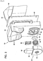
- the power tool system 10 comprises a hand-held power tool 12 and a charger 20.
- the power tool 12 comprises a tool main body 14 and a first battery pack 16.
- the tool main body 14 has an internal motor, which rotationally drives a tool and a tool shaft or chuck 18.
- the first battery pack 16 has a plurality of internal secondary batteries (e.g., lithium-ion cells) and supplies the drive current to the motor in response to the user's operation of a trigger 19.
- the first battery pack 16 can be attached to and detached from the tool main body 14.
- one or a plurality of secondary battery cells may be directly built into the tool main body 14.
- the charger 20 comprises a charger main body (base) 22 and a battery power supply 26.
- the charger main body 22 and the battery power supply 26 can be fixed or attached to (e.g., hooked onto) a hip belt 40 to be worn by the user. In this way, the user can put on and carry the charger 20 while moving (e.g., while working). If the user is right handed, then the charger main body 22 should be disposed on the right side of the user's body; on the other hand, if the user is left handed, then the charger main body 22 should be disposed on the left side of the user's body. In such arrangements, the user can easily and conveniently attach the power tool 12 to and detach the power tool 12 from the charger main body 22.
- the battery power supply 26 is preferably disposed on or at the back of the user so that it does not interfere with the user's work, although the battery power supply 26 may be disposed at any other convenient or non-obstructive position on the user's body. That is, one or more parts of the charger 20 is (are) not limited to being fixed or attached to the hip belt 40, and may instead be fixable or attachable to some other accessory or clothing of the user, such as a back pack, a pants pocket, a shirt pocket, a necklace, etc. Alternatively, one or more parts of the charger 20 may be fixable directly to the user's body such as via an arm band (strap), a leg band (strap), etc.
- the power tool 12 may include a charging adapter, which is further explained below, and can be attached to and detached from the charger main body 22. The charger main body 22 supplies the charging power to the attached power tool 12 for charging the first battery pack 16.
- the battery power supply 26 comprises a second battery pack 28 and a battery (power source) interface 30.
- a plurality of secondary battery cells e.g., lithium-ion cells
- the second battery pack 28 can be attached to and detached from the battery interface 30. That is, the second battery pack 28 has two or more terminals configured or adapted to electrically connect with corresponding terminals of the battery (power source) interface 20.
- the second battery pack 28 preferably outputs a voltage between 10-40 volts, more preferably between 18-36 volts, even more preferably between 25-36 volts.
- the second battery pack 28 also preferably outputs a current greater than 0.7 amps, more preferably greater than 1.0 amp, more preferably greater than 3.0 amp, even more preferably greater than 10.0 amp.
- the battery interface 30 is permanently or detachably fixable or attachable to the hip belt 40.
- the battery interface 30 is electrically connected to the charger main body 22 through an electrical cord 24.
- the battery interface 30 is electrically connected to the attached second battery pack 28. Electric power discharged by the second battery pack 28 is supplied to the charger main body 22 through the battery interface 30 and the electrical cord 24.
- the electric power supplied to the charger main body 22 is supplied to the power tool 12, and thereby the first battery pack 16 of the power tool 12 is charged. Accordingly, the charger 20 of the present embodiment can charge the power tool 12 without the need of an external power supply (e.g., an electrical outlet connected to a commercial power supply or a portable generator).
- an external power supply e.g., an electrical outlet connected to a commercial power supply or a portable generator.
- the battery power supply 26 is independent of or separate from the charger main body 22, it may be formed integrally therewith.
- at least one secondary battery may be built into the charger main body 22 or the battery power supply 26.
- the charger 20 may directly receive electric power from an external power supply without having a battery power supply 26.
- the present embodiment a battery pack that is manufactured for a power tool is used as the second battery pack 28 of the battery power supply 26. Therefore, the second battery pack 28 is attached directly to the tool main body 14 instead of to the first battery pack 16, and can supply the drive current to the tool main body 14.
- the first battery pack 16 and the second battery pack 28 may be the same product with equal capacity and voltage, or may be separate products wherein the capacity and/or the voltage is (are) different.
- the charger main body 22 comprises a housing cover 46 affixed to a housing plate 44.
- a belt hook 42 is configured to engage (hang over) the hip belt 40 and is provided on the housing plate 44.
- a holding member (cradle) 62 is provided on the housing cover 46.
- the holding member 62 is supported by a shaft 56 and is rotatable relative to the housing cover 46.
- the shaft 56 is inserted through a hole 50, which is formed in the housing cover 46, into a center hole 64, which is formed in the holding member 62.
- a flange 54 is located at a base end of the shaft 56 and is disposed on the inner side of the housing cover 46.
- a torsion spring 58 is provided between the housing cover 46 and the holding member 62.
- One end of the torsion spring 58 is fixed to the housing cover 46, and the other end of the torsion spring 58 is fixed to the holding member 62.
- the elastic force of the torsion spring 58 holds the holding member 62 at a normal position (i.e., the first rotation position).
- the torsion spring 58 urges the holding member 62 toward (to return to) the normal position.
- the charger main body 22 and rotatable holding member 62 may be considered as a type of rotatable charging cradle.
- a protruding part 66 is formed in or on the holding member 62.
- the protruding part 66 is generally plate shaped and a tip 68 thereof tapers.
- the protruding part 66 extends in the radial direction of the rotary shaft 56 (i.e., the center hole 64) of the holding member 62.
- the protruding part 66 of the holding member 62 is insertable into a receiving part, which is formed on the power tool 12, to thereby attach the power tool 12 to the charger main body 22.
- the tip 68 of the protruding part 66 is located upward, i.e., extends in the vertical direction. Therefore, the user can easily and conveniently attach the power tool 12 to the charger main body 22 as will be further discussed below.
- the holding member 62 is configured such that the power tool 12 can be attached in only one specific orientation.
- charging output terminals 60 are provided on the holding member 62, which is rotatably attached to the charger main body 22.
- the charging output terminals 60 are configured or adapted to output the charging current (power) to the power tool 12.
- the charging output terminals 60 electrically connect to the power tool 12.
- the charging output terminals 60 of the present embodiment include a pair of contact type terminals made of metal and are disposed in the projecting part 66 at a rear surface 62b of the holding member 62.
- the rear surface 62b of the holding member 62 opposes a front surface of the charger main body 22 across a gap and the charging output terminals 60 are disposed in that gap. According to this configuration, the charging output terminals 60 are not exposed to the outside environment, and thereby are protected.
- guides 48 are provided on the front surface of the housing cover 46.
- the guides 48 guide the power tool 12 toward the holding member 62.
- the guides 48 of the present embodiment include a pair of walls that generally extends in the vertical directions. Further, the spacing between the guides 48 is wider at its upper part than at its lower part.
- the configuration of the guides 48 is not limited thereto and any shape capable of assisting the user to bring the power tool 12 into contact with the protruding part 66 is encompassed by the present teachings.
- lock walls 52 are provided on the front surface of the housing cover 48.
- the lock walls 52 extend arcuately around the hole 50, which supports the shaft 56. More preferably, the lock walls 52 extend along the rotational direction of the holding member 62.
- the lock walls 52 are formed on both the left and right sides of the hole 50 (i.e., of the rotary shaft 56 of the holding member 62), and are not formed in the area above the hole 50. That is, the lock walls 52 are not formed in the direction in which the power tool 12 will normally be attached to the protruding part 66.
- the lock walls 52 constitute part of the lock mechanism, which is designed to prevent the power tool 12 from coming off of the holding member 62.
- the lock walls 52 are preferably formed around at least a portion of the circumference of the rotary shaft 56 of the holding member 62, they need not necessarily be formed arcuately.
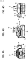
- the power tool 12 comprises a charging adapter 70 that is detachably attachable to the power tool 12.
- the charging adapter 70 comprises a connector 82 connected to an electrical cord 76.
- the connector 82 is physically and electrically connectable to the tool main body 14, such that the charging adapter 70 is electrically connectable to the power tool 12 (i.e., the first battery pack 16) through the electrical cord 76.
- the charging adapter 70 can be fixed to either the left or the right side of the power tool 12 in accordance with the user's handedness.
- a receiving hole 72 is formed in the charging adapter 70.
- the receiving hole 72 is configured to receive the protruding part 66 of the charger main body 22 with a small clearance therebetween.
- Charging input terminals 74 are provided inside the receiving hole 72, as shown in Figs. 4A and 4C .
- the charging input terminals 74 are configured to receive the charging current (power) from the charger 20.
- the charging input terminals 74 electrically connect to the charging output terminals 60 of the charger main body 22.
- the charging input terminals 74 of the present embodiment include a pair of contact type terminals that are made of metal.
- the charging input terminals 74 are located inside the receiving hole 72, and therefore are not exposed to the outside, and thereby are protected. Furthermore, the charging output terminals 60 and the charging input terminals 74 may instead be noncontact type (e.g., wireless type) terminals, for example, electromagnetic induction coils that enable power to be transmitted from the charging main body 22 to the power tool 12 via an alternating electromagnetic field.
- noncontact type e.g., wireless type
- electromagnetic induction coils that enable power to be transmitted from the charging main body 22 to the power tool 12 via an alternating electromagnetic field.
- a lock projection 80 is formed in the outer surface of the charging adapter 70.
- a lock mechanism may be formed by the lock projection 80 and the above-described lock walls 52. When the lock projection 80 contacts the lock walls 52, it prevents the power tool 12 from coming off of the holding member 62.
- the representative lock mechanism will be explained in further detail below.
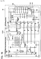
- the first battery pack 16 of the power tool 12 comprises a plurality of secondary battery cells 102.
- the secondary battery cells 102 are connected in series to a pair of power output terminals 114.
- each of the secondary battery cells 102 is preferably a lithium-ion cell.
- the first battery pack 16 comprises a cell monitor circuit 110, which monitors the voltage, the temperature, and the electric (discharge) current of the plurality of secondary battery cells 102.
- a temperature sensor 106 which measures the temperature of the secondary battery cells 102
- a shunt resistor 108 which measures the electric (discharge) current of the secondary battery cells 102
- each electrode of each of the secondary battery cells 102 is likewise connected to the cell monitor circuit 110.
- the first battery pack 16 further comprises a battery controller 112.
- the battery controller 112 is connected to the cell monitor circuit 110 and controls the charging and discharging of the secondary battery cells 102 in accordance with the detected voltage, temperature, and electric current of the secondary battery cells 102. However, the battery controller 112 does not directly control the charging and discharging of the secondary battery cells 102.
- the battery controller 112 outputs a control signal to the tool main body 14 as needed, and, in accordance with this control signal, the tool main body 14 directly controls the discharging of the secondary battery cells 102.
- the battery controller 112 outputs a control signal to the tool main body 14 as needed, and, in accordance with this control signal, the tool main body 14 directly controls the discharging of the secondary battery cells 102.
- the tool main body 14 comprises a motor 126 connected to a pair of power input terminals 122.
- the pair of power input terminals 122 is electrically connectable to the pair of power output terminals 114 of the first battery pack 16, and receives the current (power) discharged from the first battery pack 16.
- the motor 126 drives the tool, which is attached to the tool shaft or chuck 18, using the electric power from the first battery pack 16.
- a main switch 124 and a semiconductor switch 128 are provided between the power input terminals 122 and the motor 126.
- the main switch 124 is connected to the trigger 19 and outputs a signal in response to the user's operation of the trigger 19.
- the tool main body 14 comprises a tool controller 130.
- the tool controller 130 uses pulse width modulation ("PWM") to control the semiconductor switch 128 in accordance with the output signal from the main switch 124.
- PWM pulse width modulation
- the semiconductor switch 128 can be forcibly turned off in response to a stop signal from the battery controller 112, e.g., in case a battery temperature, voltage or current discharge limit is/are reached.
- the tool main body 14 further comprises a pair of adapter connection terminals 132, which are respectively connectable, i.e. one-to-one, to the pair of power input terminals 122.
- the pair of adapter connection terminals 132 is electrically connected to the charging adapter 70 and receives the charging current (power) from the charger 20. This charging current (power) is supplied to the first battery pack 16 through the tool main body 14.
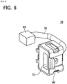
- the charging adapter 70 comprises a pair of tool connection terminals 142 that are provided on the connector 82 of the charging adapter 70 shown in FIG. 6 .
- the pair of tool connection terminals 142 is connected, one-to-one, to the pair of charging input terminals 74 of the charging adapter 70.
- the pair of tool connection terminals 142 is electrically connected to the pair of adapter connection terminals 132 of the tool main body 14.
- the charging adapter 70 further comprises an adapter controller 146 that is communicatively connected to, i.e. is in electrical communication with, the tool controller 130.
- the adapter controller 146 is connected to a gate of a semiconductor switch 144 (e.g., a FET) via a drive circuit 152.
- the adapter controller 146 is configured or adapted to turn the semiconductor switch 144 on and off, to thereby start and stop the charging as needed.
- the charging adapter 70 comprises a charger detection circuit 154 that is connected to the adapter controller 146.
- the charger detection circuit 154 comprises a zener diode 154a and a transistor 154b.
- the zener diode 154a is connected between the charging input terminals 74 via a positive temperature characteristic (PTC) thermistor 158.
- PTC positive temperature characteristic
- a voltage from the charger 20 is applied across the charging input terminals 74, and a prescribed voltage is also generated by the zener diode 154a.
- the voltage generated by the zener diode 154a is applied across the source and gate of the transistor 154b, which turns on.
- the drain of the transistor 154b is connected to the adapter controller 146, and a prescribed signal (i.e., ground or floating) is input to the adapter controller 146 in accordance with the ON/OFF state of the transistor 154b.
- a prescribed signal i.e., ground or floating
- the charger detection circuit 154 detects whether the charging adapter 70 is attached to the charger 20 by monitoring the voltage between the charging input terminals 74.
- the detection result of the charger detection circuit 154 is input to the adapter controller 146 and is transmitted from the adapter controller 146 to the tool controller 130 as well as from the tool controller 130 to the battery controller 112.
- a diode 156 is interposed (connected) between the charger detection circuit 154 and the positive electrode side (+) tool connection terminal 142.
- the diode 156 is oriented so as to permit current to flow from the positive electrode side (+) charging input terminal 74 to the positive electrode side (+) tool connection terminal 142 and to inhibit the flow of a reverse current. Because the voltage from the first battery pack 16 is applied across the tool connection terminals 142, if the diode 156 were absent, then the charger detection circuit 154 would detect the voltage from the battery pack 16 and mistakenly determine that the charger 20 is connected. That is, the diode 156 is provided to prevent such a mistaken determination.
- the diode 156 ensures that the voltage between the charging input terminals 74 promptly returns to zero without being affected by the voltage from the first battery pack 18. Therefore, when the user detaches the power tool 12 from the charger 20, that change in circumstance is immediately detected by the charger detection circuit 154. As a result, the adapter controller 146, the tool controller 130, and the battery controller 112 can rapidly switch from a charging operation to a discharging operation so that the user can promptly start using the power tool 12.
- the pair of charging output terminals 60 is provided on the charger main body 22 and a pair of power input terminals 172 is provided on the battery interface 30.
- the pair of power input terminals 172 is electrically connected to the second battery pack 28 and receives the current (power) discharged from the second battery pack 28.
- the pair of power input terminals 172 is connected to the pair of charging output terminals 60 via a semiconductor switch 162 (e.g., a FET) and a DC/DC converter 170.
- the voltage of the current (power) discharged from the second battery pack 28 is lowered or raised by the DC/DC converter 170 as needed, and is then output from the pair of charging output terminals 60 to the charging adapter 70. Because the charger main body 22 comprises the DC/DC converter 170, the rated voltage of the second battery pack 28 may differ from the rated voltage of the first battery pack 16.
- the charger main body 22 further comprises a charging controller 168.
- the charging controller 168 can communicatively connect to, i.e. can be in electrical communication with, the adapter controller 146 of the charging adapter 70. Furthermore, the charging controller 168 and the adapter controller 146 can communicate data through the charging output terminals 60 and the charging input terminals 74 without a connection line for data communication.
- the charging controller 168 is connected to the gate of the semiconductor switch 162 via a drive circuit 164.
- the charging controller 168 can turn the semiconductor switch 162 on and off to thereby start and stop the charging as needed.
- a tool detection circuit 166 is connected to the charging controller 168.
- the tool detection circuit 166 detects whether the charger main body 22 is attached to the power tool 12 by monitoring the voltage between the charging output terminals 60.
- the second battery pack 28 of the charger 20 comprises a plurality of secondary battery cells 188 and a pair of power output terminals 182.
- the plurality of secondary battery cells 188 is preferably connected in series to the pair of power output terminals 182, although various arrangements, e.g., series and/or parallel connections, of the battery cells 188 is possible in accordance with the present teachings.
- the pair of power output terminals 182 is electrically connected to the pair of power input terminals 172 of the battery interface 30 and outputs the current (power) discharged from the secondary battery cells 188 to the battery interface 30.
- Each of the secondary battery cells 188 is, for example, a lithium-ion cell.
- the second battery pack 28 comprises a cell monitor circuit 186, which monitors the voltage, the temperature, and the electric current of the plurality of secondary battery cells 188.
- a temperature sensor 190 which measures the temperature of the secondary battery cells 188
- a shunt resistor 192 which measures the electric current of the secondary battery cells 188, are connected to the cell monitor circuit 186.
- each of the electrodes of each of the secondary battery cells 188 is also connected to the cell monitor circuit 186.
- the second battery pack 28 further comprises a battery controller 184.
- the battery controller 184 is connected to the cell monitor circuit 186 and controls the discharging of the secondary battery cells 188 in accordance with the detected voltage, temperature, and electric current of the secondary battery cells 188.
- the battery controller 184 does not directly control the discharging of the secondary battery cells 188. Instead, the battery controller 184 outputs a control signal as needed to the charging controller 168, which, in accordance with this control signal, directly controls the discharging of the secondary battery cells 188. In this system, there is no need to provide a semiconductor switch inside the second battery pack 28 in order to electrically disconnect the secondary battery cells 188.
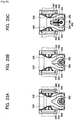
- FIG. 8A shows a state immediately before the power tool 12 is attached to the charger main body 22.
- the charger main body 22 is fixed to the hip belt 40, which is worn by the user, and the power tool 12 is held in the user's right hand. (The user's body and right hand are not shown for clarity purposes.)
- FIG. 8A when the user lowers his or her right hand, which is holding the power tool 12, in natural or normal position, a grip 13 of the power tool 12 becomes substantially horizontal, and the power tool 12 becomes laterally oriented.
- the holding member 62 is maintained at its normal position by the torsion spring 58, such that the tip 68 of the protruding part 66 is oriented upward (vertical).
- the charging adapter 70 of the power tool 12 is at a position that is spaced apart from the charger main body 22.
- the charging input terminals 74 of the charging adapter 70 and the charging output terminals 60 of the charger main body 22 are not in contact with one another.
- the lock projection 80 of the charging adapter 70 is also positioned spaced apart from the charger main body 22.
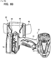
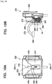
- FIG. 8B shows a state immediately after the power tool 12 has been attached to the charger main body 22.
- the user can attach the power tool 12 to the charger main body 22 by naturally lowering his or her right hand, which holds the power tool 12.
- the charging adapter 70 of the power tool 12 is guided by the guides 48.
- the protruding part 66 of the holding member 62 is thereby inserted into the receiving hole 72 of the charging adapter 70, and the charging input terminals 74 of the charging adapter 70 come into contact with the charging output terminals 60 of the charger main body 22.
- the charging input terminals 74 and the charging output terminals 60 are electrically connected and the charging of the first battery pack 16 is started.
- the charging adapter 70 of the power tool 12 can be attached to the holding member 62 in only one specific orientation prohibits the reverse connection of the charging input terminals 74 and the charging output terminals 60.
- the lock projection 80 of the charging adapter 70 is positioned on the charger main body 22. However, the lock projection 80 is still not in contact with the lock walls 52 of the charger main body 22.
- FIG. 8C shows a state wherein the power tool 12, which is attached to the charger main body 22, has rotated downward owing to its intrinsic weight (i.e. due to gravity). That is, if the user releases his or her hand from the power tool 12 after the power tool 12 has been attached to the charger main body 22, the power tool 12, together with the holding member 62, will rotate downward owing to its intrinsic weight (gravity). The center of gravity of the power tool 12 moves to a location vertically below the rotary shaft 56 of the holding member 62, and the attitude of the power tool 12 is stable. As shown in FIG.
- the lock walls 52 are formed arcuately, the gaps between the lock projection 80 and the lock walls 52 do not vary (or the lock projection 80 and the lock walls 52 stay in continuous contact), even if the power tool 12 swings. Therefore, the power tool 12 will not rattle when it swings.
- the charger main body 22 is worn on the left side of the user's body, and the charging adapter 70 is fixed to the side surface on the opposite side of the power tool 12.
- a power tool system of a second embodiment will now be explained with reference to FIG. 11 .
- the system of the present embodiment differs from the system 10 of the first embodiment only in the structure of the charger main body 22.
- the charger main body 22 of the present embodiment is specialized for right-handed users, and the holding member 62 can rotate in only one direction.
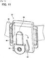
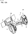
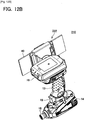
- a power tool system 210 of a third embodiment will now be explained with reference to FIGS. 12-20 .
- the system 210 of the present embodiment differs from the system 10 of the first embodiment in that the system 210 comprises a charger main body (base) 222 and a charging adapter 270.
- the power tool 12 is not modified.
- a battery power supply is connected to the charger main body 222 via an electrical cord.
- the circuit structure of the present embodiment is also substantially the same as that of the first embodiment.
- the battery power supply may utilize the same second battery pack 28 as the first embodiment described above.
- the power tool 12 which has the charging adapter 270 attached thereto (discussed below), also can be attached to and detached from the charger main body 222. After being attached to the charger main body 222, the power tool 12 can rotate downward due to its intrinsic weight (i.e. by gravity). Furthermore, when the power tool 12 is attached to the charger main body 222, the power tool 12 is electrically connected to the charger main body 222, and the charging of the first battery pack 16 starts.
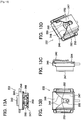
- the charger main body 222 comprises a housing cover 246 fixed to a housing plate 244.
- a belt hook 242 is configured or adapted to engage with (hang over) the hip belt 40 and is provided on the housing plate 244.
- a holding member 262 is provided on the housing cover 246.
- the holding member 262 is supported by a shaft 256 and can rotate relative to the housing cover 246.
- a torsion spring (not shown) is provided between the housing cover 246 and the holding member 262 similar to the first embodiment. The torsion spring thus urges the holding member 262 toward its normal position (i.e., the first rotation position).
- a receiving groove 266 is provided on the holding member 262 and has a semicircular shape that is capable of receiving a disk shaped protruding part 272 of the power tool 12. Therefore, the holding member 262 is configured to receive the protruding part 272 of the power tool 12, which is further discussed below, and thereby hold the power tool 12.
- the receiving groove 266 is upwardly (vertically) open. Accordingly, the user can easily mate the protruding part 272 of the power tool 12 with the receiving groove 266 of the charger main body 222 by downwardly moving the power tool 12.
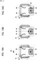
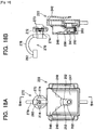
- Charging output terminals 260 are provided on the charger main body 222 as shown in FIG. 13A .
- the charging output terminals 260 are configured or adapted to output the charging current (power) to the power tool 12.
- the charging output terminals 260 electrically connect to the power tool 12.
- the charging output terminals 260 of the present embodiment include a pair of contact type terminals made of metal.
- the charging output terminals 260 are disposed inside the receiving groove 266 of the holding member 262. According to this configuration, the charging output terminals 260 are not exposed to the outside, and thereby are protected.
- the charger main body 222 further comprises a guide cover 247.
- the guide cover 247 is fixed to the housing cover 246 and partially covers the holding member 262.
- An upper part of the guide cover 247 is notched in a V-shape, the edges of which constitute guides 248.
- a slot is formed in the guide cover 247 and extends downward continuously from the lower ends of the guides 248.
- the left and right edges of the slot constitute lock walls 252 according to the present embodiment.
- the lock walls 252 are located on both the left and right sides of the rotary shaft 256 of the holding member 262.
- the lock walls 252 constitute part of the lock mechanism of the present embodiment and prevent the power tool 12 from coming off of the holding member 262.
- FIG. 15A when the holding member 262 is disposed in or at its normal position, the receiving groove 266 of the holding member 262 is upwardly (vertically) open.
- the lock walls 252 are not present above the holding member 262.
- the power tool 12 can be attached to and detached from the holding member 262.
- the receiving groove 266 of the holding member 262 is open to the side.
- the lock walls 252 are formed on either side of the holding member 262. Accordingly, when the holding member 262 rotates from the normal position, the power tool 12 can no longer come off of the holding member 262.
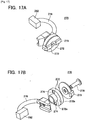
- the charging adapter 270 can be attached to and detached from the power tool 12. As shown in FIGS. 17A and 17B , the charging adapter 270 comprises a connector 282 connected to an electrical cord 276.
- the connector 282 is physically and electrically connectable to the tool main body 14, such that the charging adapter 270 is electrically connected to the power tool 12 (i.e., the first battery pack 16) through the electrical cord 276.
- the charging adapter 270 is fixable to either the right or left sides of the power tool 12 in accordance with the user's handedness.
- the protruding part 272 is formed in the charging adapter 270 and has a disk shape, as was noted above. Ribs 273 extend in the radial direction and are disposed on the front surface of the protruding part 272.
- the protruding part 272 is supported by a shaft 278.
- Charging input terminals 274 are provided on a rear surface 272b of the protruding part 272.
- the charging input terminals 274 electrically connect to the charging output terminals 260 of the charger main body 222.
- the charging input terminals 274 of the present embodiment include a pair of contact type terminals made of metal that are located on the rear surface 272b of the protruding part 272. In this case, the charging input terminals 274 are not exposed to the outside, and are thereby protected.
- the charging output terminals 260 and the charging input terminals 274 may instead be noncontact type (i.e., wireless type) terminals, for example, they may be electromagnetic induction coils similar to the alternate embodiment of the first embodiment.
- the holding member 262 of the charger main body 222 is maintained at the normal position by the torsion spring. At this time, the receiving groove 266 of the holding member 262 is facing upward.
- the charging adapter 270 of the power tool 12 is at a position that is spaced apart from the charger main body 222, and the charging input terminals 274 of the charging adapter 270 and the charging output terminals 260 of the charger main body 222 are not in contact with one another.
- the guides 248 guide the charging adapter 270 (i.e., the power tool 12) to the holding member 262.
- the protruding part 272 of the charging adapter 270 mates with the receiving groove 266 of the holding member 262. Therefore, the charging input terminals 274 of the charging adapter 270 contact the charging output terminals 260 of the charger main body 22. The charging input terminals 274 and the charging output terminals 260 are electrically connected, and the charging of the first battery pack 16 is started. Because the protruding part 272 is discoidal, the protruding part 272 can mate with the receiving groove 266 of the holding member 262 even without the user paying much attention to the position, the orientation, and the like of the power tool 12.
- the charging adapter 270 is held by the holding member 262 and rotates (refer to FIG. 12B ) together with the power tool 12 owing to the intrinsic weight of the power tool 12 (i.e. due to gravity).
- the holding member 262 faces sideways, and a shaft portion 272c of the protruding part 272 of the charging adapter 270 opposes the lock walls 252.
- the protruding part 272 of the charging adapter 270 is thereby prohibited from coming off of the receiving groove 266 of the holding member 62, and the power tool 12 is prevented from coming off of the charger main body 222.
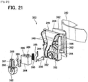
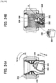
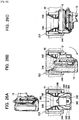
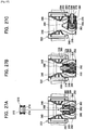
- the power tool system according to a fourth embodiment will now be explained with reference to FIGS. 21-29 .
- the system of the present embodiment differs from the system 10 of the first embodiment primarily in the configuration of a charger main body 322 (refer to FIGS. 21 , 22A-22C , 23A-23C , 24A and 24B ) and the configuration of a charging adapter 370 (refer to FIGS. 25A-25E ). Other aspects of the configuration are substantially unchanged.
- the battery power supply is connected to the charger main body 322 via the electrical cord, as in the first embodiment shown in FIG. 1 .
- the circuit structure of the present embodiment may be substantially identical to that of the first embodiment shown in FIGS. 7A and 7B .
- the charger main body (base) 322 comprises a belt hook 342 configured or adapted to be detachably attached to (or engaged with) a belt 340 worn around the hip of the user, a housing plate 344 and a housing cover 346.
- a pair of guides 348 and a pair of lock walls 352 are provided on the housing cover 346.
- the pair of guides 348 and the pair of lock walls 352 are each formed in mirror symmetry along a vertical line between them (refer to FIG. 23A ).
- a holding member (cradle) 362 is provided on the charger main body 322.
- the holding member 362 is supported by a shaft 356 and is rotatable relative to the housing cover 346. That is, the shaft 356 is the rotary shaft (i.e., the center of rotation) of the holding member 362.
- the holding member 362 also has a protruding part 366 that extends in the radial direction of the rotary shaft 356 of the holding member 362.
- a tip 368 of the protruding part 366 tapers.
- the protruding part 366 is configured or adapted to be inserted into the charging adapter 370, which is fixed to the power tool 12, to thereby attach the power tool 12 to the charger main body 322.
- the holding member 362 is urged toward its normal position (i.e., the first rotation position) such that the tip 368 of the protruding part 366 is positioned upward (vertically).
- the holding member 362 is configured or adapted such that it can rotate from the normal position in either the one direction (i.e., the clockwise direction) or the other direction (i.e., the counterclockwise direction).
- the torsion spring 58 explained in the first embodiment is not provided.
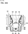
- charging output terminals 360 are (pivotably) provided on the charger main body 322.
- the charging output terminals 360 are configured or adapted to output the charging current (power) to the power tool 12.
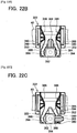
- the charging output terminals 360 include a pair of contact type terminals made of metal that are disposed on both side surfaces of the protruding part 366 of the holding member 362 (e.g., refer to FIG. 22B ). Therefore, the arrangement of the pair of charging output terminals 360 differs from the arrangement in the first embodiment.
- a movable member 384 is provided on the charger main body 322.
- the movable member 384 is slidably supported by the holding member 362, and covers at least a portion of the protruding part 366 of the holding member 362. That is, the movable member 384 is configured or adapted such that it can slide relative to the holding member 362.
- the protruding part 366 of the holding member 362 is inserted into a through hole 386 of the movable member 384.
- the movable member 384 is capable of moving from a (top or distal) first location (refer to FIG.
- an urging member 390 is provided on the charger main body 322.
- the urging member 390 may comprise a spring, e.g., a compression spring, or another resiliently elastic material that returns to its normal shape or form after a load is removed from it.
- the urging member 390 is supported by the holding member 362.
- the urging member 390 is disposed inside a groove 367, which is formed in the holding member 362.
- the groove 367 extends in the radial direction along the protruding part 366.
- the urging member 390 is positioned between the movable member 384 and the holding member 362 and is configured to urge the movable member 384 toward the first location regardless of the rotational position of the holding member 362.
- the movable member 384 further comprises a sliding projection 388, which protrudes toward the housing cover 346. Furthermore, a hollow or recessed part 392 is formed or defined in the housing cover 346 and receives or accommodates the sliding projection 388 of the movable member 384.
- the hollow part 392 has a laterally symmetric shape (i.e. it exhibits mirror symmetry along a vertical line). As shown in FIG. 24B , by holding or retaining the sliding projection 388 of the movable member 384 inside the hollow part 392, the movable member 384 is prevented from coming off of the holding member 362.
- Circumferential edges 394 of the hollow part 392 are slide surfaces, against or along which the sliding projection 388 slides in order to follow the rotation of the holding member 362.
- a distance R (refer to FIG. 24B ) from the rotary shaft 356 of the holding member 362 to the slide surface 394 in the radial direction of the rotary shaft 356 varies along the circumferential direction of the rotary shaft 356 over at least part of each of the slide surfaces 394. Specifically, the distance R is maximal at a portion 396 at which the sliding projection 388 makes contact when the holding member 362 is disposed at the normal position, and the distance R decreases as the holding member 362 becomes more spaced apart from the portion 396.
- the movable member 384 moves (in direction S1) from the first location to the second location.
- the holding member 362 rotates (in direction R2) toward the normal position
- the movable member 384 moves (in direction S2) from the second location to the first location. That is, the rotational motion of the holding member 362 is coupled to (i.e. it influences) the sliding motion of the movable member 384.
- the movable member 384 is urged by the urging member 390 toward the first location.
- the holding member 362 also is urged by the same urging member 390 toward the normal position.
- a recessed part 396 which is recessed in the radial direction of the rotary shaft 356, is formed at the vertically uppermost part of the slide surfaces 394, i.e. at the portion that the sliding projection 388 contacts when the holding member 362 is at the normal position.
- the sliding projection 388 of the movable member 384 fits into the recessed part 396.
- a rotation restricting member (e.g., a stop) 398 is provided in the hollow part 392.
- the rotation-restricting member 398 can be attached to and detached from the hollow part 392.
- the holding member 362 is restricted to rotating from the normal position in only one direction. That is, when the rotation restricting member 398 is attached to a left side portion of the hollow part 392 as shown in FIG. 24B , the holding member 362 is permitted to rotate away from the normal position only in the clockwise direction (refer to FIGS. 23B , 24B ).
- the rotation-restricting member 398 when the rotation-restricting member 398 is attached to a right side portion of the hollow part 392 (not shown), the holding member 362 is permitted to rotate away from the normal position only in the counterclockwise direction. If the user is right handed and thus the charging main body 322 will be worn on the user's right side, the rotation restricting member 398 should be attached to the left side portion of the hollow part 392 as shown in FIG. 24B so that the power tool 12 is rotatable only in the user's forward direction. On the other hand, if the user is left handed and thus the charging main body 322 will be worn on the user's left side, then the rotation-restricting member 398 should be attached to the right side portion of the hollow part 392.
- the charging adapter 370 is preferably configured to be attached to and detached from the power tool 12. As shown in FIGS. 25A and 25B , the charging adapter 370 is electrically connected to the tool body 14 via an electrical cord 376. A connector 382 is connected to the tip of the electrical cord 376 such that the electrical cord 376 can be rotated with respect to the tool body 14.
- a right-handed user can rotate the charging adapter 370, using the connector 382 as a fulcrum, and fix the charging adapter 370 to a left side side surface of the tool body 14 such that the charging adapter 370 is located on the left side of the tool body 14.
- a left-handed user can rotate the charging adapter 370, using the connector 382 as a fulcrum, and fix the connector 382 to a right side side surface of the tool body 14 such that the charging adapter 370 is located on the right side of the tool body 14.
- the connector 382 rotatably supporting the electrical cord 376, the electrical cord 376 can be disposed along a side surface of the tool body 14 regardless of which side surface of the tool body 14 the user attaches the charging adapter 370 to.
- the charging adapter 370 has a receiving hole 372 configured to receive and accommodate the protruding part 366 of the charger main body 322, e.g., with a small clearance.
- Charging input terminals 374 are provided inside the receiving hole 372 and are configured or adapted receive the charging current (power) from the charger 20.
- the charging input terminals 374 of the present embodiment include a pair of contact type terminals made of metal that are respectively disposed on an upper side inner surface and a lower side inner surface---one terminal per surface---of the receiving hole 372. That is, the arrangement of the pair of charging input terminals 374 is modified from the arrangement of the first embodiment.
- a lock projection 380 is formed or defined on the outer surface of the charging adapter 370.
- a lock mechanism may include the lock projection 380 and the lock walls 352 discussed above.
- FIG. 26A shows a state immediately before the user attaches the power tool 12 to the charger main body 322.
- the charging adapter 370 of the power tool 12 is at a position that is spaced apart from (above) the charger main body 322.
- the movable member 384 of the charger main body 322 is at the first location where it shields the charging output terminals 360.
- the lock projection 380 of the charging adapter 370 is also at a position that is spaced apart from (above) the charger main body 322.
- the sliding projection 388 of the movable member 384 is interference-fit in the recessed part 396 defined at the top of the slide surfaces 394, such that the holding member 362 is maintained at the normal position.
- FIG. 26B shows a state immediately after the power tool 12 has been attached to the charger main body 322.
- the protruding part 366 of the holding member 362 is inserted into the receiving hole 372 of the charging adapter 370, and the charging input terminals 374 of the charging adapter 370 contact the charging output terminals 360 of the charger main body 322, such that the charging operation can begin.
- the movable member 384 has been pushed downwardly by the charging adapter 370 and has moved to its second location. When the movable member 384 moves to the second location, at least a portion of an inner surface of the through hole 386 of the movable member 384 wipes or scrapes the surfaces of the charging output terminals. 360.
- any foreign matter adhered to the charging output terminals 360 is dislodged and removed.
- the lock projection 380 of the charging adapter 370 is still not in contact with the lock walls 352 of the charger main body 322.
- the sliding projection 388 of the movable member 384 separates from the recessed part 396 of the slide surfaces 394. As a result, the holding member 362 becomes rotatable.
- FIG. 26C shows a state wherein the power tool 12, which is attached to the charger main body 322, has rotated downward due to its intrinsic weight (i.e. due to gravity).
- the charging adapter 370 and the holding member 362 rotate together, and therefore the electrical connection between the charging input terminals 374 and the charging output terminals 360 is maintained. Namely, the charging operation is not interrupted by the rotation of the power tool 12.
- the lock projection 380 of the charging adapter 370 comes into contact with the inner sides of the lock walls 352 of the charger main body 322. Consequently, the power tool 12 becomes locked in the charger main body 322 so that it can not fall off.
- the sliding projection 388 of the movable member 384 is spaced apart from the slide surfaces 394 of the charger main body 322. Accordingly, the rotation of the holding member 362 and the power tool 12 is not hindered by the sliding projection 388.
- the above-described procedure is simply reversed. More specifically, the (right-handed) user rotates the power tool 12, which is suspended from the charger main body 322, counterclockwise (i.e., from the position shown in FIG. 26C to the position shown in FIG. 26B ). Subsequently, the power tool 12 is extracted or withdrawn upward from the charger main body 322 (i.e., from the position shown in FIG. 26B to the position shown in FIG. 26A ). In the state shown in FIG. 26B , the power tool 12 is urged, together with the movable member 384, upward by the urging member 390.
- the urging member 390 urges the power tool 12, which is attached to the holding member 362, in the direction that causes the power tool 12 to detach from the holding member 362, thereby providing a force that assists the user's lifting movement.
- the user can detach the power tool 12 from the charger main body 322 more easily (i.e. with the application of less lifting force to the power tool 12) than if the urging member 390 did not supply this power tool removal assisting force.
- a configuration is adopted wherein the same urging member 390 urges the movable member 384 toward the first location and urges the holding member 362 toward the normal position and wherein the urging is in the direction in which the power tool 12 detaches.
- the charger main body 22, 222, 322 is described shown as being physically separate, but electronically connectable, with the battery interface 30 in the above-described representative embodiments, of course, these components may also be designed so as to be physically connected with no seams therebetween.
- a separate charging adapter 70, 270, 370 has been provided in the representative embodiments for conducting charging current to the battery pack 16, of course, the charging input terminals may instead be directly affixed on or in the battery pack 16, thereby eliminating the need for a separate charging adapter.
Landscapes
- Engineering & Computer Science (AREA)
- Power Engineering (AREA)
- Textile Engineering (AREA)
- Mechanical Engineering (AREA)
- Charge And Discharge Circuits For Batteries Or The Like (AREA)
- Secondary Cells (AREA)
- Workshop Equipment, Work Benches, Supports, Or Storage Means (AREA)
- Portable Power Tools In General (AREA)
Claims (14)
- Chargeur (20) pour outil électrique portatif (12), comprenant :une interface de source d'alimentation (30),une base (22 ; 222 ; 322) de chargeur, etun support de charge (62 ; 262 ; 362) supporté en rotation sur la base de chargeur,le support de charge rotatif (62 ; 262 ; 362) incluant au moins deux bornes de sortie de charge (60 ; 260 ; 360) électriquement connectées à l'interface de source d'alimentation (30), et caractérisé en ce que :le chargeur (20) comprend des moyens (40, 42 ; 40, 242 ; 340, 342) pour attacher de manière détachable l'interface de source d'alimentation (30) et la base (22 ; 222 ; 322) de chargeur au corps d'un utilisateur, dans lequel les moyens de fixation comprennent une ceinture (40 ; 340), une sangle ou un harnais adapté pour être porté sur le corps de l'utilisateur.
- Chargeur (20) selon la revendication 1, comprenant en outre :au moins un élément (188) de batterie électriquement connecté à l'interface de source d'alimentation (30) et adapté pour apporter un courant de charge aux bornes de sortie de charge (60 ; 260 ; 360).
- Chargeur (20) selon la revendication 2, dans lequel l'au moins un élément (188) de batterie est disposé dans un bloc-batteries (28) de chargeur ayant des bornes (182) adaptées pour pouvoir être électriquement connectées à des bornes correspondantes (172) de l'interface de source d'alimentation (30) et en être électriquement déconnectées, le bloc-batteries de chargeur étant adapté pour sortir une tension entre 10-40 volts, plus préférablement entre 18-36 volts, encore plus préférablement entre 25-36 volts.
- Chargeur (20) selon la revendication 3, dans lequel le bloc-batteries (28) de chargeur est adapté pour sortir un courant de charge d'au moins 0,7 ampère, plus préférablement d'au moins 1,0 ampère, plus préférablement d'au moins 3,0 ampères et encore plus préférablement d'au moins 10 ampères.
- Chargeur (20) selon l'une quelconque des revendications précédentes, dans lequel les moyens de fixation comprennent au moins un crochet (42 ; 242 ; 342).
- Chargeur (20) selon l'une quelconque des revendications 1-5, comprenant en outre un élément de poussée (58 ; 390) adapté pour pousser le support de charge (62 ; 262 ; 362) vers une première position de rotation, dans laquelle des bornes d'entrée de charge (74, 274 ; 374) de l'outil électrique portatif (12), ou d'un adaptateur de charge (70 ; 270 ; 370) optionnel qui est physiquement et électriquement connecté à l'outil électrique portatif, peuvent être attachées au support de charge rotatif.
- Chargeur (20) selon l'une quelconque des revendications 1-6, dans lequel le support de charge rotatif (362) est configuré de telle sorte que les bornes de sortie de charge (360) sont exposées par rotation du support de charge par rapport à la base (322) de chargeur loin de la première position de rotation.
- Chargeur (20) selon la revendication 7, comprenant en outre un couvercle mobile (384) adapté pour couvrir les bornes de sortie de charge (360) lorsque le support de charge (362) est dans la première position de rotation et pour découvrir les bornes de sortie de charge lorsque le support de charge est tourné loin de la première position de rotation.
- Chargeur selon la revendication 8, dans lequel le couvercle mobile (384) peut coulisser par rapport au support de charge (362) entre un premier emplacement qui couvre les bornes de sortie de charge (360) et un second emplacement qui découvre les bornes de sortie de charge.
- Chargeur (20) selon l'une quelconque des revendications 1-9, comprenant en outre un premier mécanisme de verrouillage (52 ; 252 ; 352) adapté pour empêcher l'outil électrique portatif (12) de se détacher du support de charge (62 ; 262 ; 362) lorsque le support de charge n'est pas disposé dans la première position de rotation, l'outil électrique portatif pouvant être détaché du support de charge dans la première position de rotation.
- Chargeur selon l'une quelconque des revendications 1-10, comprenant en outre au moins un guide (48 ; 248 ; 348) disposé sur la base (22 ; 222 ; 322) de chargeur et adapté pour guider les bornes d'entrée de charge (74, 274 ; 374) de l'outil électrique portatif (12) vers le support de charge (62 ; 262 ; 362).
- Système d'outil électrique comprenant :le chargeur (20) selon l'une quelconque des revendications 1-11, etun outil électrique portatif (12) comprenant :des bornes d'entrée de charge (74, 274 ; 374) adaptées pour se connecter électriquement aux bornes de sortie de charge (60 ; 260 ; 360), etau moins un élément (102) de batterie électriquement connecté aux bornes d'entrée de charge.
- Système d'outil électrique selon la revendication 12, dans lequel l'outil électrique (12) comprend en outre un adaptateur de charge (70 ; 270 ; 370) qui inclut les bornes d'entrée de charge (74, 274 ; 374), l'adaptateur de charge étant adapté pour conduire le courant de charge entre le chargeur (20) et l'au moins un élément (102) de batterie.
- Procédé de charge du système d'outil électrique selon l'une quelconque des revendications 12 et 13, comprenant :la mise en contact des bornes d'entrée de charge (74, 274 ; 374) de l'outil électrique (10) avec les bornes de sortie de charge (60 ; 260 ; 360) du chargeur (20),la rotation du support de charge (62 ; 262 ; 362) et de l'outil électrique par rapport à la base de charge (22 ; 222 ; 322) alors que les bornes d'entrée de charge sont en contact avec les bornes de sortie de charge, etl'apport du courant de charge à l'au moins un élément (102) de batterie alors que l'au moins un élément de batterie est connecté à l'outil électrique et alors que le support de charge et l'outil électrique sont autorisés à osciller librement par rapport à la base de chargeur.
Applications Claiming Priority (4)
| Application Number | Priority Date | Filing Date | Title |
|---|---|---|---|
| US201161511092P | 2011-07-24 | 2011-07-24 | |
| US201161581950P | 2011-12-30 | 2011-12-30 | |
| US201261664928P | 2012-06-27 | 2012-06-27 | |
| PCT/JP2012/004605 WO2013014889A2 (fr) | 2011-07-24 | 2012-07-19 | Chargeur pour outil électrique portatif, système d'outil électrique et procédé de charge d'une batterie d'outil électrique |
Publications (2)
| Publication Number | Publication Date |
|---|---|
| EP2735075A2 EP2735075A2 (fr) | 2014-05-28 |
| EP2735075B1 true EP2735075B1 (fr) | 2016-06-01 |
Family
ID=47045106
Family Applications (1)
| Application Number | Title | Priority Date | Filing Date |
|---|---|---|---|
| EP12775057.8A Active EP2735075B1 (fr) | 2011-07-24 | 2012-07-19 | Chargeur pour outil électrique portatif, système d'outil électrique et procédé de charge d'une batterie d'outil électrique |
Country Status (5)
| Country | Link |
|---|---|
| US (2) | US9577450B2 (fr) |
| EP (1) | EP2735075B1 (fr) |
| JP (2) | JP6067675B2 (fr) |
| CN (1) | CN103718421B (fr) |
| WO (1) | WO2013014889A2 (fr) |
Cited By (1)
| Publication number | Priority date | Publication date | Assignee | Title |
|---|---|---|---|---|
| US11338427B2 (en) | 2019-01-10 | 2022-05-24 | Milwaukee Electric Tool Corporation | Power tool |
Families Citing this family (50)
| Publication number | Priority date | Publication date | Assignee | Title |
|---|---|---|---|---|
| JP5593200B2 (ja) | 2010-10-27 | 2014-09-17 | 株式会社マキタ | 電動工具システム |
| WO2013014914A2 (fr) | 2011-07-24 | 2013-01-31 | Makita Corporation | Adaptateur pour outils électriques, système d'outil électrique et procédé de fonctionnement correspondant |
| WO2013063507A1 (fr) | 2011-10-26 | 2013-05-02 | Milwaukee Electric Tool Corporation | Suivi sans fil d'outils électriques et dispositifs associés |
| TW201445278A (zh) * | 2013-05-20 | 2014-12-01 | Hon Hai Prec Ind Co Ltd | 移動電源 |
| JP6084523B2 (ja) * | 2013-06-25 | 2017-02-22 | 株式会社マキタ | 充電器 |
| WO2015061370A1 (fr) | 2013-10-21 | 2015-04-30 | Milwaukee Electric Tool Corporation | Adaptateur pour dispositifs d'outil électrique |
| US9592744B2 (en) | 2013-12-06 | 2017-03-14 | SZ DJI Technology Co., Ltd | Battery and unmanned aerial vehicle with the battery |
| CN107742915B (zh) * | 2013-12-06 | 2021-02-19 | 深圳市大疆创新科技有限公司 | 电池以及具有该电池的飞行器 |
| US10278592B2 (en) | 2013-12-09 | 2019-05-07 | Samsung Electronics Co., Ltd. | Modular sensor platform |
| US9844340B2 (en) | 2013-12-31 | 2017-12-19 | Samsung Electronics Co., Ltd. | Electrocardiogram watch clasp |
| KR20160105396A (ko) * | 2013-12-31 | 2016-09-06 | 삼성전자주식회사 | 애플리케이션들과 연관된 배터리 충전기 |
| US10136857B2 (en) | 2014-05-23 | 2018-11-27 | Samsung Electronics Co., Ltd. | Adjustable wearable system having a modular sensor platform |
| JP2016015813A (ja) * | 2014-07-01 | 2016-01-28 | パナソニックIpマネジメント株式会社 | 電動工具用充電装置及び電動工具用充電システム |
| EP3202016B1 (fr) * | 2014-10-03 | 2021-01-13 | Robert Bosch GmbH | Étui de charge inductive pour outil électrique |
| US10041297B2 (en) * | 2015-01-26 | 2018-08-07 | Black & Decker, Inc. | Ladder |
| EP3068010A1 (fr) * | 2015-03-10 | 2016-09-14 | HILTI Aktiengesellschaft | Chargeur de batterie pouvant fonctionner en réseau et système de recharge |
| US10749430B2 (en) | 2015-03-13 | 2020-08-18 | Positec Power Tools (Suzhou) Co., Ltd. | Power transmission apparatus and control method therefor, and power supply system |
| WO2016179271A1 (fr) | 2015-05-04 | 2016-11-10 | Milwaukee Electric Tool Corporation | Outil électrique et procédé pour une communication sans fil |
| DE102015208254A1 (de) * | 2015-05-05 | 2016-11-10 | Robert Bosch Gmbh | Akkuinduktivladevorrichtung |
| CH711364A2 (de) * | 2015-07-30 | 2017-01-31 | Signode Ind Group Llc | Halteeinrichtung mit integrierter Ladestation für eine Umreifungsvorrichtung. |
| US10283984B2 (en) * | 2015-07-31 | 2019-05-07 | Bretford Manufacturing, Inc. | Charging locker |
| JP6697885B2 (ja) * | 2016-01-06 | 2020-05-27 | 株式会社マキタ | 電動作業機システム |
| JP6112495B1 (ja) * | 2016-02-19 | 2017-04-12 | パナソニックIpマネジメント株式会社 | 電子機器用ハンドストラップ |
| DE102016205773A1 (de) * | 2016-04-07 | 2017-10-12 | Robert Bosch Gmbh | Ladegerät |
| DE102016209822A1 (de) * | 2016-06-03 | 2017-12-07 | Robert Bosch Gmbh | Akkupack für eine Handwerkzeugmaschine und/oder ein Ladegerät |
| US20180056496A1 (en) * | 2016-08-26 | 2018-03-01 | Robert Bosch Tool Corporation | Modular Handheld Power Tool |
| US10447050B2 (en) * | 2016-10-11 | 2019-10-15 | Halo2Cloud, LLC | Decorative and portable power charger with motion light |
| US10536012B2 (en) * | 2016-10-11 | 2020-01-14 | Halo2Cloud, LLC | Decorative and portable power charger with motion light |
| US20180342883A1 (en) * | 2017-05-25 | 2018-11-29 | Vector Products, Inc. | Battery charger with detachable battery |
| CN215881531U (zh) | 2017-08-07 | 2022-02-22 | 米沃奇电动工具公司 | 电动工具和电动工具装置 |
| CN107441653A (zh) * | 2017-08-28 | 2017-12-08 | 苏州巨邦建设工程有限公司 | 一种便捷式安全悬挂腰带 |
| US10224728B1 (en) * | 2017-09-01 | 2019-03-05 | M-Edge International Corp. | Universal totable battery backup |
| TWI652876B (zh) | 2017-11-10 | 2019-03-01 | 昇恆科技股份有限公司 | 數位扭力手工具之充電模組 |
| CN207710762U (zh) * | 2017-11-23 | 2018-08-10 | 苏州宝时得电动工具有限公司 | 电动工具的收纳装置 |
| WO2019108621A1 (fr) | 2017-11-29 | 2019-06-06 | Milwaukee Electric Tool Corporation | Module de suivi pouvant être fixé à l'extérieur destiné à un outil électrique |
| CN109946532B (zh) * | 2017-12-21 | 2024-03-19 | 南京泉峰科技有限公司 | 适用于工具系统部件的诊断装置和诊断方法 |
| CN209107180U (zh) * | 2017-12-23 | 2019-07-16 | 天佑电器(苏州)有限公司 | 吸尘器与附件架的组合及吸尘器和附件架 |
| CN114865207A (zh) * | 2018-01-05 | 2022-08-05 | 深圳市大疆创新科技有限公司 | 手持云台 |
| CA3090555C (fr) * | 2018-02-12 | 2023-05-23 | Techtronic Cordless Gp | Bloc-batterie contenant un connecteur rotatif |
| EP3759811B1 (fr) | 2018-02-28 | 2024-04-24 | Milwaukee Electric Tool Corporation | Système et procédé de grippage simulé pour outils électriques |
| US11338405B2 (en) | 2018-02-28 | 2022-05-24 | Milwaukee Electric Tool Corporation | Eco-indicator for power tool |
| US10547036B1 (en) * | 2018-05-31 | 2020-01-28 | M-Edge International Corporation | Power interface ensemble and module for mobile consumer electronics |
| EP3808154A4 (fr) * | 2018-06-18 | 2022-04-06 | Milwaukee Electric Tool Corporation | Chauffage inductif de batteries pour charge |
| WO2020163450A1 (fr) | 2019-02-06 | 2020-08-13 | Milwaukee Electric Tool Corporation | Outil électrique à bornier partagé |
| CN113382661B (zh) * | 2019-02-12 | 2023-06-20 | 米沃奇电动工具公司 | 工具附接系统 |
| JP7193403B2 (ja) | 2019-03-29 | 2022-12-20 | 株式会社マキタ | 電源供給装置、電動作業機システム |
| US11006736B2 (en) * | 2019-08-09 | 2021-05-18 | Klein Tools, Inc. | Limited pivot quick connect |
| EP4014325A4 (fr) | 2019-08-13 | 2023-09-06 | Milwaukee Electric Tool Corporation | Porte-clés sans fil accrédité pour commander des dispositifs d'outil électrique |
| CN112847258A (zh) * | 2019-11-12 | 2021-05-28 | 苏州宝时得电动工具有限公司 | 手持电动工具 |
| AU2020386630B2 (en) | 2019-11-21 | 2023-12-07 | Milwaukee Electric Tool Corporation | Insertable wireless communication device for a power tool |
Family Cites Families (99)
| Publication number | Priority date | Publication date | Assignee | Title |
|---|---|---|---|---|
| US3629680A (en) | 1970-04-17 | 1971-12-21 | Mattel Inc | Toy battery charger |
| US4677362A (en) | 1984-08-31 | 1987-06-30 | Black & Decker, Inc. | Apparatus for storing and charging a rechargeable electric tool |
| ZA856290B (en) * | 1984-08-31 | 1987-03-25 | Black & Decker Inc | Apparatus for storing and charging a rechargeable electric tool |
| DE3444262A1 (de) | 1984-12-05 | 1986-06-05 | Alfred Teves Gmbh, 6000 Frankfurt | Fluegelzellenmotor |
| JPS61142372U (fr) | 1985-02-26 | 1986-09-03 | ||
| US4827534A (en) | 1988-05-26 | 1989-05-09 | Haugen Alvin E | Sun-powered vest |
| DE4204420A1 (de) | 1992-02-14 | 1993-08-19 | Fein C & E | Akkumulatorbetriebenes elektrowerkzeug |
| JP3154556B2 (ja) * | 1992-07-01 | 2001-04-09 | シャープ株式会社 | 電界効果トランジスタおよびその製造方法 |
| US7613590B2 (en) | 1992-11-17 | 2009-11-03 | Health Hero Network, Inc. | Modular microprocessor-based power tool system |
| JPH073983U (ja) * | 1993-06-25 | 1995-01-20 | 日立工機株式会社 | バッテリー式電動工具のバッテリーホルスター |
| DE9311901U1 (de) | 1993-08-10 | 1993-12-23 | Atlas Copco Elektrowerkzeuge | Batteriebetriebenes Elektrowerkzeug |
| US5680026A (en) | 1994-03-21 | 1997-10-21 | Tyton Corporation | Tool belt with battery assembly |
| JP2842267B2 (ja) | 1994-12-30 | 1998-12-24 | 日本電気株式会社 | 携帯無線機 |
| US5914585A (en) | 1996-02-20 | 1999-06-22 | Norand Corporation | Power sharing in computing systems with a plurality of electronic devices |
| US6043626A (en) | 1996-10-29 | 2000-03-28 | Ericsson Inc. | Auxiliary battery holder with multicharger functionality |
| JPH10275635A (ja) | 1997-03-28 | 1998-10-13 | Sanyo Electric Co Ltd | 電池を内蔵する充電器 |
| US6018231A (en) | 1997-10-02 | 2000-01-25 | Black & Decker Inc. | Battery charging system |
| US7394347B2 (en) | 1997-10-27 | 2008-07-01 | World Wide Innovations, Llc | Locking device for electronic equipment |
| US20030030342A1 (en) * | 1998-02-10 | 2003-02-13 | Chen James C. | Contactless energy transfer apparatus |
| US6218806B1 (en) | 1998-06-03 | 2001-04-17 | Black & Decker Inc. | Method and apparatus for obtaining product use information |
| US6803744B1 (en) | 1999-11-01 | 2004-10-12 | Anthony Sabo | Alignment independent and self aligning inductive power transfer system |
| US7217069B2 (en) | 2000-02-10 | 2007-05-15 | Eastway Fair Company Limited | Hand-held tool with a removable object sensor |
| EP1982798A3 (fr) | 2000-03-16 | 2008-11-12 | Makita Corporation | Outil électrique |
| JP3860035B2 (ja) | 2000-04-13 | 2006-12-20 | 株式会社マキタ | 充電装置用のアダプタ |
| JP2001300867A (ja) | 2000-04-21 | 2001-10-30 | Makita Corp | 電動工具用アダプタ |
| WO2002041465A2 (fr) * | 2000-11-20 | 2002-05-23 | Electric Fuel (E.F.L.) Ltd. | Source d'energie compacte haute capacite et caracteristiques de commande |
| JP3553585B2 (ja) | 2001-03-02 | 2004-08-11 | 日立工機株式会社 | 電動工具 |
| JP2002315198A (ja) | 2001-04-17 | 2002-10-25 | Makita Corp | 電池駆動機器 |
| DE10127821C5 (de) | 2001-06-07 | 2005-05-12 | Tool Express-Service Schraubertechnik Gmbh | Anordnung zum Betrieb eines Elektro-Schraubers |
| DE10212750B4 (de) | 2002-03-22 | 2006-04-20 | Robert Bosch Gmbh | Akkupack-System für Handwerkzeugmaschinen |
| JP3886835B2 (ja) | 2002-03-25 | 2007-02-28 | 株式会社マキタ | 充電システム |
| JP3771529B2 (ja) | 2002-03-26 | 2006-04-26 | 本田技研工業株式会社 | 芝刈機 |
| US7182147B2 (en) | 2002-06-27 | 2007-02-27 | Snap-On Incorporated | Tool apparatus, system and method of use |
| DE10238710A1 (de) | 2002-08-23 | 2004-03-04 | Metabowerke Gmbh | Elektrohandwerkzeuggerät |
| US20040070369A1 (en) | 2002-10-11 | 2004-04-15 | Makita Corporation | Adapters for battery chargers |
| US6938867B2 (en) | 2002-10-15 | 2005-09-06 | Wahl Clipper Corporation | Holder for a powered device |
| US6870089B1 (en) | 2002-11-12 | 2005-03-22 | Randolph Dean Gray | System and apparatus for charging an electronic device using solar energy |
| JP4517575B2 (ja) | 2002-11-29 | 2010-08-04 | パナソニック電工株式会社 | 電動工具 |
| JP4329369B2 (ja) | 2003-03-20 | 2009-09-09 | パナソニック電工株式会社 | 電動工具の使用支援方法及びその装置 |
| US7227335B2 (en) | 2003-07-22 | 2007-06-05 | Makita Corporation | Method and apparatus for diagnosing the condition of a rechargeable battery |
| US7357526B2 (en) | 2003-08-22 | 2008-04-15 | Milwaukee Electric Tool Corporation | Power tool and accessory |
| JP2005073350A (ja) | 2003-08-22 | 2005-03-17 | Matsushita Electric Works Ltd | 電動工具 |
| US7551894B2 (en) | 2003-10-07 | 2009-06-23 | Phonak Communications Ag | Wireless microphone |
| US6845279B1 (en) | 2004-02-06 | 2005-01-18 | Integrated Technologies, Inc. | Error proofing system for portable tools |
| US20050267998A1 (en) | 2004-05-27 | 2005-12-01 | Ferguson Alan L | Interchangeable communication modules for work machines |
| US7176656B2 (en) | 2004-06-22 | 2007-02-13 | Campbell Hausfeld/Scott Fetzer Company | Tool with battery pack |
| US7688028B2 (en) | 2004-10-18 | 2010-03-30 | Black & Decker Inc. | Cordless power system |
| US7273159B2 (en) | 2004-11-08 | 2007-09-25 | Black & Decker Inc. | Cordless power tool system with improved power output |
| US7356934B2 (en) | 2004-11-29 | 2008-04-15 | Wahl Clipper Corporation | Belt or clothing-mountable battery-powered hair clipper with holster |
| JP4678199B2 (ja) | 2005-02-10 | 2011-04-27 | パナソニック電工株式会社 | 電動工具 |
| GB2423199B (en) | 2005-02-11 | 2009-05-13 | Pa Consulting Services | Power supply systems for electrical devices |
| JP2006224208A (ja) | 2005-02-15 | 2006-08-31 | Max Co Ltd | 工具及び工程管理データ収集システム |
| US20060244414A1 (en) | 2005-04-29 | 2006-11-02 | David Lay | Device for electrical power supply to a power tool |
| US8211560B2 (en) | 2005-09-20 | 2012-07-03 | Metabowerke Gmbh | Battery pack and hand-held power tool |
| US8565839B2 (en) * | 2005-10-13 | 2013-10-22 | Abbott Medical Optics Inc. | Power management for wireless devices |
| FR2892043B1 (fr) | 2005-10-14 | 2009-04-24 | Prospection Et D Inv S Techniq | Systeme de surete antivol d'un outil a actionnement manuel portatif et l'outil adapte du systeme. |
| SE531000C2 (sv) | 2005-11-17 | 2008-11-11 | Atlas Copco Tools Ab | System för bibringande av de olika driftsegenskaper till ett batteridrivet skruvåtdragningsverktyg |
| DE502005008889D1 (de) | 2005-11-18 | 2010-03-04 | Metabowerke Gmbh | Elektrohandwerkzeuggerät und akkupack hierfür |
| US20070170220A1 (en) | 2006-01-25 | 2007-07-26 | Stiletto Tools | Tool holder with roller edge receiver |
| JP4099782B2 (ja) * | 2006-04-19 | 2008-06-11 | ソニー株式会社 | バッテリーの充電装置 |
| JP2009535007A (ja) | 2006-04-26 | 2009-09-24 | ディメイン テクノロジー プロプライエタリー リミテッド | 充電器および充電式電気装置 |
| JP4419987B2 (ja) * | 2006-05-24 | 2010-02-24 | 茂 小出 | 工具吊り下げ構造 |
| US20070276457A1 (en) | 2006-05-26 | 2007-11-29 | Lawrence Gordon | Infrared heating devices & therapy for chronic lower back pain |
| ATE535951T1 (de) | 2006-06-27 | 2011-12-15 | Boston Power Inc | Integrierte stromunterbrechungsvorrichtung für lithiumionen-zellen |
| DE202006014606U1 (de) | 2006-09-22 | 2007-01-04 | Cooper Power Tools Gmbh & Co. Ohg | Kabelloses Elektrowerkzeug und Fertigungssystem |
| EP2102961A2 (fr) | 2006-12-20 | 2009-09-23 | Techtium Ltd. | Chargeur alimente par une batterie |
| SE530667C2 (sv) | 2007-01-15 | 2008-08-05 | Atlas Copco Tools Ab | Portabelt motordrivet verktyg med trådlös kommunikation med en stationär styrenhet |
| US7838143B2 (en) | 2007-06-22 | 2010-11-23 | Boston-Power, Inc. | CID retention device for Li-ion cell |
| JP4897601B2 (ja) * | 2007-07-24 | 2012-03-14 | 外栄金物株式会社 | 工具ホルダ |
| US7863862B2 (en) | 2007-10-12 | 2011-01-04 | Research In Motion Limited | Handheld electronic device with holster having a notification device |
| GB0723914D0 (en) | 2007-12-07 | 2008-01-23 | Johnson Electric Sa | A power tool |
| DE102007061374A1 (de) | 2007-12-19 | 2009-06-25 | Robert Bosch Gmbh | Steuermodul |
| JP2009262254A (ja) | 2008-04-23 | 2009-11-12 | Katsuyuki Totsu | コードレス電動工具と非接触充電装置との組合せ |
| US20090291330A1 (en) | 2008-04-24 | 2009-11-26 | Boston-Power, Inc. | Battery with enhanced safety |
| JP4793426B2 (ja) | 2008-11-10 | 2011-10-12 | パナソニック電工株式会社 | 充電式電動工具 |
| JP2010119273A (ja) * | 2008-11-14 | 2010-05-27 | Sanyo Electric Co Ltd | 携帯機器の充電台 |
| US7808779B2 (en) | 2008-12-01 | 2010-10-05 | Lda, Llc | Rotatable dock for portable electronic devices |
| JP4835697B2 (ja) | 2009-01-08 | 2011-12-14 | パナソニック電工株式会社 | 非接触電力伝送回路 |
| JP2010206871A (ja) | 2009-02-27 | 2010-09-16 | Panasonic Electric Works Co Ltd | 非接触被充電装置ならびにそれを用いる非接触充電システムおよび電気機器 |
| JP2010226890A (ja) | 2009-03-24 | 2010-10-07 | Panasonic Electric Works Co Ltd | 非接触電力伝送装置 |
| JP3154556U (ja) | 2009-07-31 | 2009-10-22 | 株式会社セイワ | 携帯電話機用充電器 |
| JP5569717B2 (ja) | 2009-07-31 | 2014-08-13 | 日立工機株式会社 | 電池パック、該電池パックを充電する充電システム、および該電池パックを備えた電動工具 |
| DE102009029537A1 (de) | 2009-09-17 | 2011-03-31 | Robert Bosch Gmbh | Handwerkzeugmodul |
| DE102009045946A1 (de) | 2009-10-23 | 2011-04-28 | Robert Bosch Gmbh | Handwerkzeug |
| US9258394B2 (en) * | 2009-11-12 | 2016-02-09 | Arun Sobti & Associates, Llc | Apparatus and method for integrating computing devices |
| US9258523B2 (en) * | 2009-11-12 | 2016-02-09 | Arun Sobti & Associates Llc | Apparatus and method for integrating computing devices |
| WO2011060283A2 (fr) * | 2009-11-12 | 2011-05-19 | Arun Sobti & Associates, Llc | Plate-forme d'utilisateur final ayant une cavité intégrée pour recevoir fonctionnellement et physiquement un émetteur-récepteur de téléphonie cellulaire portable |
| DE102009054638A1 (de) | 2009-12-15 | 2011-06-16 | Robert Bosch Gmbh | Handwerkzeugladevorrichtung |
| DE102010039106A1 (de) | 2010-08-10 | 2012-02-16 | Hilti Aktiengesellschaft | Handwerkzeugmaschine mit Diebstahlsicherung |
| JP5663353B2 (ja) | 2010-10-27 | 2015-02-04 | 株式会社マキタ | 電動工具システム |
| JP5593200B2 (ja) | 2010-10-27 | 2014-09-17 | 株式会社マキタ | 電動工具システム |
| US8842429B2 (en) * | 2011-01-04 | 2014-09-23 | Motorola Mobility Llc | Method and apparatus for securing portable electronic device to accessory device |
| DE102011005646A1 (de) | 2011-03-16 | 2012-09-20 | Hilti Aktiengesellschaft | Mobiles Ladegerät |
| US9077053B2 (en) | 2011-07-20 | 2015-07-07 | Milwaukee Electric Tool Corporation | Battery charger including multiple charging ports on surfaces forming an apex |
| WO2013014914A2 (fr) | 2011-07-24 | 2013-01-31 | Makita Corporation | Adaptateur pour outils électriques, système d'outil électrique et procédé de fonctionnement correspondant |
| US8947495B2 (en) * | 2011-12-06 | 2015-02-03 | Alcatel Lucent | Telepresence apparatus for immersion of a human image in a physical environment |
| US9781496B2 (en) | 2012-10-25 | 2017-10-03 | Milwaukee Electric Tool Corporation | Worksite audio device with wireless interface |
| US20150171638A1 (en) | 2013-12-13 | 2015-06-18 | Go-Tech Energy Co., Ltd. | Charger for rechargeable battery and charging method thereof |
| US9979213B2 (en) * | 2015-08-20 | 2018-05-22 | Michael Kidakarn | Animated battery charging assembly |
-
2012
- 2012-07-19 CN CN201280036992.2A patent/CN103718421B/zh active Active
- 2012-07-19 WO PCT/JP2012/004605 patent/WO2013014889A2/fr active Application Filing
- 2012-07-19 EP EP12775057.8A patent/EP2735075B1/fr active Active
- 2012-07-19 US US14/233,804 patent/US9577450B2/en active Active
- 2012-07-19 JP JP2014503344A patent/JP6067675B2/ja active Active
-
2016
- 2016-12-21 JP JP2016247629A patent/JP6326480B2/ja active Active
-
2017
- 2017-01-10 US US15/402,584 patent/US10090692B2/en active Active
Cited By (1)
| Publication number | Priority date | Publication date | Assignee | Title |
|---|---|---|---|---|
| US11338427B2 (en) | 2019-01-10 | 2022-05-24 | Milwaukee Electric Tool Corporation | Power tool |
Also Published As
| Publication number | Publication date |
|---|---|
| US9577450B2 (en) | 2017-02-21 |
| JP2014525218A (ja) | 2014-09-25 |
| US10090692B2 (en) | 2018-10-02 |
| EP2735075A2 (fr) | 2014-05-28 |
| JP6067675B2 (ja) | 2017-01-25 |
| US20140159640A1 (en) | 2014-06-12 |
| JP2017099275A (ja) | 2017-06-01 |
| WO2013014889A2 (fr) | 2013-01-31 |
| US20170126038A1 (en) | 2017-05-04 |
| JP6326480B2 (ja) | 2018-05-16 |
| CN103718421A (zh) | 2014-04-09 |
| WO2013014889A3 (fr) | 2013-05-23 |
| CN103718421B (zh) | 2016-08-17 |
Similar Documents
| Publication | Publication Date | Title |
|---|---|---|
| US10090692B2 (en) | Charger for hand-held power tool, power tool system and method of charging a power tool battery | |
| US10886762B2 (en) | Lithium-based battery pack for a hand held power tool | |
| EP3120976B1 (fr) | Alimentation électrique de type backpack | |
| US8143850B2 (en) | Inductive charger battery replacement system and device | |
| EP2869970B1 (fr) | Alimentation électrique de type sac à dos | |
| EP2735077B1 (fr) | Système de charge de bloc-batterie portable et procédé de recharge de bloc-batterie | |
| EP2929612B1 (fr) | Dispositif de charge | |
| US8890468B2 (en) | Portable power supply | |
| US20150194647A1 (en) | Backpack-Type Power Supply | |
| CN101147308A (zh) | 一种能够进行无线数据和电能传输的非接触式充电器及使用该充电器的充电电池包及移动设备 | |
| US20140001853A1 (en) | Charger and power supply system | |
| JP2010200561A (ja) | 充電装置 | |
| KR100414680B1 (ko) | 모바일 폰의 휴대용 충전장치 |
Legal Events
| Date | Code | Title | Description |
|---|---|---|---|
| PUAI | Public reference made under article 153(3) epc to a published international application that has entered the european phase |
Free format text: ORIGINAL CODE: 0009012 |
|
| 17P | Request for examination filed |
Effective date: 20140221 |
|
| AK | Designated contracting states |
Kind code of ref document: A2 Designated state(s): AL AT BE BG CH CY CZ DE DK EE ES FI FR GB GR HR HU IE IS IT LI LT LU LV MC MK MT NL NO PL PT RO RS SE SI SK SM TR |
|
| DAX | Request for extension of the european patent (deleted) | ||
| 17Q | First examination report despatched |
Effective date: 20150429 |
|
| GRAP | Despatch of communication of intention to grant a patent |
Free format text: ORIGINAL CODE: EPIDOSNIGR1 |
|
| INTG | Intention to grant announced |
Effective date: 20160203 |
|
| GRAS | Grant fee paid |
Free format text: ORIGINAL CODE: EPIDOSNIGR3 |
|
| GRAA | (expected) grant |
Free format text: ORIGINAL CODE: 0009210 |
|
| AK | Designated contracting states |
Kind code of ref document: B1 Designated state(s): AL AT BE BG CH CY CZ DE DK EE ES FI FR GB GR HR HU IE IS IT LI LT LU LV MC MK MT NL NO PL PT RO RS SE SI SK SM TR |
|
| REG | Reference to a national code |
Ref country code: GB Ref legal event code: FG4D |
|
| REG | Reference to a national code |
Ref country code: CH Ref legal event code: EP Ref country code: AT Ref legal event code: REF Ref document number: 804404 Country of ref document: AT Kind code of ref document: T Effective date: 20160615 |
|
| REG | Reference to a national code |
Ref country code: IE Ref legal event code: FG4D |
|
| REG | Reference to a national code |
Ref country code: DE Ref legal event code: R096 Ref document number: 602012019219 Country of ref document: DE |
|
| REG | Reference to a national code |
Ref country code: LT Ref legal event code: MG4D |
|
| REG | Reference to a national code |
Ref country code: NL Ref legal event code: MP Effective date: 20160601 |
|
| PG25 | Lapsed in a contracting state [announced via postgrant information from national office to epo] |
Ref country code: NO Free format text: LAPSE BECAUSE OF FAILURE TO SUBMIT A TRANSLATION OF THE DESCRIPTION OR TO PAY THE FEE WITHIN THE PRESCRIBED TIME-LIMIT Effective date: 20160901 Ref country code: LT Free format text: LAPSE BECAUSE OF FAILURE TO SUBMIT A TRANSLATION OF THE DESCRIPTION OR TO PAY THE FEE WITHIN THE PRESCRIBED TIME-LIMIT Effective date: 20160601 Ref country code: FI Free format text: LAPSE BECAUSE OF FAILURE TO SUBMIT A TRANSLATION OF THE DESCRIPTION OR TO PAY THE FEE WITHIN THE PRESCRIBED TIME-LIMIT Effective date: 20160601 |
|
| REG | Reference to a national code |
Ref country code: AT Ref legal event code: MK05 Ref document number: 804404 Country of ref document: AT Kind code of ref document: T Effective date: 20160601 |
|
| PG25 | Lapsed in a contracting state [announced via postgrant information from national office to epo] |
Ref country code: LV Free format text: LAPSE BECAUSE OF FAILURE TO SUBMIT A TRANSLATION OF THE DESCRIPTION OR TO PAY THE FEE WITHIN THE PRESCRIBED TIME-LIMIT Effective date: 20160601 Ref country code: SE Free format text: LAPSE BECAUSE OF FAILURE TO SUBMIT A TRANSLATION OF THE DESCRIPTION OR TO PAY THE FEE WITHIN THE PRESCRIBED TIME-LIMIT Effective date: 20160601 Ref country code: RS Free format text: LAPSE BECAUSE OF FAILURE TO SUBMIT A TRANSLATION OF THE DESCRIPTION OR TO PAY THE FEE WITHIN THE PRESCRIBED TIME-LIMIT Effective date: 20160601 Ref country code: HR Free format text: LAPSE BECAUSE OF FAILURE TO SUBMIT A TRANSLATION OF THE DESCRIPTION OR TO PAY THE FEE WITHIN THE PRESCRIBED TIME-LIMIT Effective date: 20160601 Ref country code: ES Free format text: LAPSE BECAUSE OF FAILURE TO SUBMIT A TRANSLATION OF THE DESCRIPTION OR TO PAY THE FEE WITHIN THE PRESCRIBED TIME-LIMIT Effective date: 20160601 Ref country code: GR Free format text: LAPSE BECAUSE OF FAILURE TO SUBMIT A TRANSLATION OF THE DESCRIPTION OR TO PAY THE FEE WITHIN THE PRESCRIBED TIME-LIMIT Effective date: 20160902 Ref country code: NL Free format text: LAPSE BECAUSE OF FAILURE TO SUBMIT A TRANSLATION OF THE DESCRIPTION OR TO PAY THE FEE WITHIN THE PRESCRIBED TIME-LIMIT Effective date: 20160601 |
|
| PG25 | Lapsed in a contracting state [announced via postgrant information from national office to epo] |
Ref country code: BE Free format text: LAPSE BECAUSE OF NON-PAYMENT OF DUE FEES Effective date: 20160731 |
|
| PG25 | Lapsed in a contracting state [announced via postgrant information from national office to epo] |
Ref country code: RO Free format text: LAPSE BECAUSE OF FAILURE TO SUBMIT A TRANSLATION OF THE DESCRIPTION OR TO PAY THE FEE WITHIN THE PRESCRIBED TIME-LIMIT Effective date: 20160601 Ref country code: CZ Free format text: LAPSE BECAUSE OF FAILURE TO SUBMIT A TRANSLATION OF THE DESCRIPTION OR TO PAY THE FEE WITHIN THE PRESCRIBED TIME-LIMIT Effective date: 20160601 Ref country code: IS Free format text: LAPSE BECAUSE OF FAILURE TO SUBMIT A TRANSLATION OF THE DESCRIPTION OR TO PAY THE FEE WITHIN THE PRESCRIBED TIME-LIMIT Effective date: 20161001 Ref country code: IT Free format text: LAPSE BECAUSE OF FAILURE TO SUBMIT A TRANSLATION OF THE DESCRIPTION OR TO PAY THE FEE WITHIN THE PRESCRIBED TIME-LIMIT Effective date: 20160601 Ref country code: SK Free format text: LAPSE BECAUSE OF FAILURE TO SUBMIT A TRANSLATION OF THE DESCRIPTION OR TO PAY THE FEE WITHIN THE PRESCRIBED TIME-LIMIT Effective date: 20160601 Ref country code: EE Free format text: LAPSE BECAUSE OF FAILURE TO SUBMIT A TRANSLATION OF THE DESCRIPTION OR TO PAY THE FEE WITHIN THE PRESCRIBED TIME-LIMIT Effective date: 20160601 |
|
| PG25 | Lapsed in a contracting state [announced via postgrant information from national office to epo] |
Ref country code: BE Free format text: LAPSE BECAUSE OF FAILURE TO SUBMIT A TRANSLATION OF THE DESCRIPTION OR TO PAY THE FEE WITHIN THE PRESCRIBED TIME-LIMIT Effective date: 20160601 Ref country code: PL Free format text: LAPSE BECAUSE OF FAILURE TO SUBMIT A TRANSLATION OF THE DESCRIPTION OR TO PAY THE FEE WITHIN THE PRESCRIBED TIME-LIMIT Effective date: 20160601 Ref country code: PT Free format text: LAPSE BECAUSE OF FAILURE TO SUBMIT A TRANSLATION OF THE DESCRIPTION OR TO PAY THE FEE WITHIN THE PRESCRIBED TIME-LIMIT Effective date: 20161003 Ref country code: SM Free format text: LAPSE BECAUSE OF FAILURE TO SUBMIT A TRANSLATION OF THE DESCRIPTION OR TO PAY THE FEE WITHIN THE PRESCRIBED TIME-LIMIT Effective date: 20160601 Ref country code: AT Free format text: LAPSE BECAUSE OF FAILURE TO SUBMIT A TRANSLATION OF THE DESCRIPTION OR TO PAY THE FEE WITHIN THE PRESCRIBED TIME-LIMIT Effective date: 20160601 |
|
| REG | Reference to a national code |
Ref country code: CH Ref legal event code: PL |
|
| REG | Reference to a national code |
Ref country code: DE Ref legal event code: R097 Ref document number: 602012019219 Country of ref document: DE |
|
| PG25 | Lapsed in a contracting state [announced via postgrant information from national office to epo] |
Ref country code: MC Free format text: LAPSE BECAUSE OF FAILURE TO SUBMIT A TRANSLATION OF THE DESCRIPTION OR TO PAY THE FEE WITHIN THE PRESCRIBED TIME-LIMIT Effective date: 20160601 |
|
| PLBE | No opposition filed within time limit |
Free format text: ORIGINAL CODE: 0009261 |
|
| STAA | Information on the status of an ep patent application or granted ep patent |
Free format text: STATUS: NO OPPOSITION FILED WITHIN TIME LIMIT |
|
| PG25 | Lapsed in a contracting state [announced via postgrant information from national office to epo] |
Ref country code: FR Free format text: LAPSE BECAUSE OF NON-PAYMENT OF DUE FEES Effective date: 20160801 Ref country code: CH Free format text: LAPSE BECAUSE OF NON-PAYMENT OF DUE FEES Effective date: 20160731 Ref country code: LI Free format text: LAPSE BECAUSE OF NON-PAYMENT OF DUE FEES Effective date: 20160731 |
|
| REG | Reference to a national code |
Ref country code: FR Ref legal event code: ST Effective date: 20170331 |
|
| REG | Reference to a national code |
Ref country code: IE Ref legal event code: MM4A |
|
| 26N | No opposition filed |
Effective date: 20170302 |
|
| GBPC | Gb: european patent ceased through non-payment of renewal fee |
Effective date: 20160901 |
|
| PG25 | Lapsed in a contracting state [announced via postgrant information from national office to epo] |
Ref country code: DK Free format text: LAPSE BECAUSE OF FAILURE TO SUBMIT A TRANSLATION OF THE DESCRIPTION OR TO PAY THE FEE WITHIN THE PRESCRIBED TIME-LIMIT Effective date: 20160601 Ref country code: SI Free format text: LAPSE BECAUSE OF FAILURE TO SUBMIT A TRANSLATION OF THE DESCRIPTION OR TO PAY THE FEE WITHIN THE PRESCRIBED TIME-LIMIT Effective date: 20160601 |
|
| PG25 | Lapsed in a contracting state [announced via postgrant information from national office to epo] |
Ref country code: GB Free format text: LAPSE BECAUSE OF NON-PAYMENT OF DUE FEES Effective date: 20160901 Ref country code: IE Free format text: LAPSE BECAUSE OF NON-PAYMENT OF DUE FEES Effective date: 20160719 |
|
| PG25 | Lapsed in a contracting state [announced via postgrant information from national office to epo] |
Ref country code: LU Free format text: LAPSE BECAUSE OF NON-PAYMENT OF DUE FEES Effective date: 20160719 |
|
| PG25 | Lapsed in a contracting state [announced via postgrant information from national office to epo] |
Ref country code: CY Free format text: LAPSE BECAUSE OF FAILURE TO SUBMIT A TRANSLATION OF THE DESCRIPTION OR TO PAY THE FEE WITHIN THE PRESCRIBED TIME-LIMIT Effective date: 20160601 Ref country code: HU Free format text: LAPSE BECAUSE OF FAILURE TO SUBMIT A TRANSLATION OF THE DESCRIPTION OR TO PAY THE FEE WITHIN THE PRESCRIBED TIME-LIMIT; INVALID AB INITIO Effective date: 20120719 |
|
| PG25 | Lapsed in a contracting state [announced via postgrant information from national office to epo] |
Ref country code: MK Free format text: LAPSE BECAUSE OF FAILURE TO SUBMIT A TRANSLATION OF THE DESCRIPTION OR TO PAY THE FEE WITHIN THE PRESCRIBED TIME-LIMIT Effective date: 20160601 Ref country code: MT Free format text: LAPSE BECAUSE OF NON-PAYMENT OF DUE FEES Effective date: 20160731 |
|
| PG25 | Lapsed in a contracting state [announced via postgrant information from national office to epo] |
Ref country code: BG Free format text: LAPSE BECAUSE OF FAILURE TO SUBMIT A TRANSLATION OF THE DESCRIPTION OR TO PAY THE FEE WITHIN THE PRESCRIBED TIME-LIMIT Effective date: 20160601 |
|
| PG25 | Lapsed in a contracting state [announced via postgrant information from national office to epo] |
Ref country code: AL Free format text: LAPSE BECAUSE OF FAILURE TO SUBMIT A TRANSLATION OF THE DESCRIPTION OR TO PAY THE FEE WITHIN THE PRESCRIBED TIME-LIMIT Effective date: 20160601 Ref country code: TR Free format text: LAPSE BECAUSE OF FAILURE TO SUBMIT A TRANSLATION OF THE DESCRIPTION OR TO PAY THE FEE WITHIN THE PRESCRIBED TIME-LIMIT Effective date: 20160601 |
|
| PGFP | Annual fee paid to national office [announced via postgrant information from national office to epo] |
Ref country code: DE Payment date: 20230531 Year of fee payment: 12 |