EP2728347B1 - Ultrasonic flaw detection method and ultrasonic array probe - Google Patents
Ultrasonic flaw detection method and ultrasonic array probe Download PDFInfo
- Publication number
- EP2728347B1 EP2728347B1 EP12802866.9A EP12802866A EP2728347B1 EP 2728347 B1 EP2728347 B1 EP 2728347B1 EP 12802866 A EP12802866 A EP 12802866A EP 2728347 B1 EP2728347 B1 EP 2728347B1
- Authority
- EP
- European Patent Office
- Prior art keywords
- flaw
- distance
- vibration insulating
- echo
- transducer
- Prior art date
- Legal status (The legal status is an assumption and is not a legal conclusion. Google has not performed a legal analysis and makes no representation as to the accuracy of the status listed.)
- Active
Links
- 239000000523 sample Substances 0.000 title claims description 55
- 238000001514 detection method Methods 0.000 title description 7
- 238000012360 testing method Methods 0.000 claims description 140
- 230000035945 sensitivity Effects 0.000 description 18
- 230000005540 biological transmission Effects 0.000 description 11
- 238000009434 installation Methods 0.000 description 11
- 238000000034 method Methods 0.000 description 10
- 238000010586 diagram Methods 0.000 description 8
- 238000009826 distribution Methods 0.000 description 6
- 230000007423 decrease Effects 0.000 description 4
- XLYOFNOQVPJJNP-UHFFFAOYSA-N water Substances O XLYOFNOQVPJJNP-UHFFFAOYSA-N 0.000 description 3
- 238000010276 construction Methods 0.000 description 2
- 230000008878 coupling Effects 0.000 description 2
- 238000010168 coupling process Methods 0.000 description 2
- 238000005859 coupling reaction Methods 0.000 description 2
- 230000000694 effects Effects 0.000 description 2
- 238000011156 evaluation Methods 0.000 description 2
- 239000000463 material Substances 0.000 description 2
- 230000010355 oscillation Effects 0.000 description 2
- 101150009729 Pal2 gene Proteins 0.000 description 1
- 101150051586 RIM21 gene Proteins 0.000 description 1
- 230000003466 anti-cipated effect Effects 0.000 description 1
- 239000007799 cork Substances 0.000 description 1
- 230000003247 decreasing effect Effects 0.000 description 1
- 230000007547 defect Effects 0.000 description 1
- 238000003745 diagnosis Methods 0.000 description 1
- 230000000149 penetrating effect Effects 0.000 description 1
- 239000011347 resin Substances 0.000 description 1
- 229920005989 resin Polymers 0.000 description 1
- 239000005060 rubber Substances 0.000 description 1
Images


Classifications
-
- G—PHYSICS
- G01—MEASURING; TESTING
- G01N—INVESTIGATING OR ANALYSING MATERIALS BY DETERMINING THEIR CHEMICAL OR PHYSICAL PROPERTIES
- G01N29/00—Investigating or analysing materials by the use of ultrasonic, sonic or infrasonic waves; Visualisation of the interior of objects by transmitting ultrasonic or sonic waves through the object
- G01N29/22—Details, e.g. general constructional or apparatus details
- G01N29/24—Probes
-
- G—PHYSICS
- G01—MEASURING; TESTING
- G01N—INVESTIGATING OR ANALYSING MATERIALS BY DETERMINING THEIR CHEMICAL OR PHYSICAL PROPERTIES
- G01N29/00—Investigating or analysing materials by the use of ultrasonic, sonic or infrasonic waves; Visualisation of the interior of objects by transmitting ultrasonic or sonic waves through the object
- G01N29/04—Analysing solids
- G01N29/041—Analysing solids on the surface of the material, e.g. using Lamb, Rayleigh or shear waves
-
- G—PHYSICS
- G01—MEASURING; TESTING
- G01N—INVESTIGATING OR ANALYSING MATERIALS BY DETERMINING THEIR CHEMICAL OR PHYSICAL PROPERTIES
- G01N29/00—Investigating or analysing materials by the use of ultrasonic, sonic or infrasonic waves; Visualisation of the interior of objects by transmitting ultrasonic or sonic waves through the object
- G01N29/04—Analysing solids
- G01N29/07—Analysing solids by measuring propagation velocity or propagation time of acoustic waves
-
- G—PHYSICS
- G01—MEASURING; TESTING
- G01N—INVESTIGATING OR ANALYSING MATERIALS BY DETERMINING THEIR CHEMICAL OR PHYSICAL PROPERTIES
- G01N29/00—Investigating or analysing materials by the use of ultrasonic, sonic or infrasonic waves; Visualisation of the interior of objects by transmitting ultrasonic or sonic waves through the object
- G01N29/22—Details, e.g. general constructional or apparatus details
- G01N29/221—Arrangements for directing or focusing the acoustical waves
-
- G—PHYSICS
- G01—MEASURING; TESTING
- G01N—INVESTIGATING OR ANALYSING MATERIALS BY DETERMINING THEIR CHEMICAL OR PHYSICAL PROPERTIES
- G01N29/00—Investigating or analysing materials by the use of ultrasonic, sonic or infrasonic waves; Visualisation of the interior of objects by transmitting ultrasonic or sonic waves through the object
- G01N29/22—Details, e.g. general constructional or apparatus details
- G01N29/223—Supports, positioning or alignment in fixed situation
-
- G—PHYSICS
- G01—MEASURING; TESTING
- G01N—INVESTIGATING OR ANALYSING MATERIALS BY DETERMINING THEIR CHEMICAL OR PHYSICAL PROPERTIES
- G01N29/00—Investigating or analysing materials by the use of ultrasonic, sonic or infrasonic waves; Visualisation of the interior of objects by transmitting ultrasonic or sonic waves through the object
- G01N29/22—Details, e.g. general constructional or apparatus details
- G01N29/24—Probes
- G01N29/2456—Focusing probes
-
- G—PHYSICS
- G01—MEASURING; TESTING
- G01N—INVESTIGATING OR ANALYSING MATERIALS BY DETERMINING THEIR CHEMICAL OR PHYSICAL PROPERTIES
- G01N29/00—Investigating or analysing materials by the use of ultrasonic, sonic or infrasonic waves; Visualisation of the interior of objects by transmitting ultrasonic or sonic waves through the object
- G01N29/22—Details, e.g. general constructional or apparatus details
- G01N29/32—Arrangements for suppressing undesired influences, e.g. temperature or pressure variations, compensating for signal noise
-
- G—PHYSICS
- G01—MEASURING; TESTING
- G01N—INVESTIGATING OR ANALYSING MATERIALS BY DETERMINING THEIR CHEMICAL OR PHYSICAL PROPERTIES
- G01N2291/00—Indexing codes associated with group G01N29/00
- G01N2291/10—Number of transducers
- G01N2291/106—Number of transducers one or more transducer arrays
Definitions
- the present invention relates to an ultrasonic testing method for performing flaw testing by using an ultrasonic array probe. More particularly, the invention relates to an ultrasonic testing method for facilitating detection of a flaw near a surface of a test object.
- flaw echo is buried in surface echo, so that the detection of flaw may be difficult.
- Patent Literature 1 is directed to an ultrasonic diagnosis which is capable of switching an ultrasonic beam shape as needed by covering a part of a transmission-reception surface with the periphery of an opening.
- the present invention has been made to solve the above-described problems with the prior arts, and an object thereof is to provide an ultrasonic testing method capable of facilitating detection of a flaw existing near a surface of a test object.
- the present inventor conducted studies earnestly and obtained a finding that by installing a vibration insulating member having the configuration described below onto a transducer surface, the range of distance from the surface of test object in which surface echo appears is made narrow, and also the intensity of flaw echo is changed. Hereunder, this finding will be explained.
- the vibration insulating member was installed onto the transducer surface as described below.
- the vibration insulating member has an opening part, and the dimension of the width of opening part (hereinafter, referred also to as an opening part width) is smaller than the width dimension of the transducer surface.
- the vibration insulating member absorbs the vibrations of the transducer surface.
- the width of opening part refers to the size of opening part in the direction perpendicular to the arrangement direction of transducers in the state in which the vibration insulating member has been installed onto the transducer surface.
- the width of transducer surface refers to the size of the transducer surface in the direction perpendicular to the arrangement direction of transducers.
- the vibration insulating member was installed so as to come into contact with the transducer surface of an ultrasonic array probe (hereinafter, referred also to as an array probe).
- a part of the transducer surface in the width direction of the transducer surface is exposed through the opening part.
- a portion exposed by the opening part of the transducer surface as described above is referred to as an exposed surface. Since the width of opening part is narrower than the width of transducer surface, the width of exposed surface is narrower than the width of the transducer surface.
- the vibration insulating member In the state in which the vibration insulating member had been installed onto the transducer surface, the vibration insulating member absorbed the vibrations of a region with which the vibration insulating member is in contact in the transducer surface.
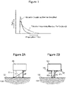
- Figure 1 is a schematic diagram showing the distributions of propagation time of surface echo in the case where the above-described vibration insulating member has been installed onto a transducer surface and in the case where the vibration insulating member has not been installed onto the transducer surface.
- the abscissas represent propagation time, and the ordinates represent the ratio of surface echo at each propagation time.
- the distribution of propagation time of surface echo in the case where the vibration insulating member has been installed onto the transducer surface is narrowed to the short time side as compared with the case where the vibration insulating member has not been installed.
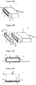
- Figures 2A and 2B are schematic views showing propagation paths of ultrasonic waves reflected by a surface of a test object, which are viewed from the transducer arrangement direction.
- Figure 2A is a schematic view showing propagation paths in the case where a vibration insulating member has not been installed onto a transducer surface
- Figure 2B is a schematic view showing propagation paths in the case where the vibration insulating member has been installed onto the transducer surface.
- the length of a propagation path E through which the ultrasonic waves transmitted from a transducer surface 111 of an array probe 101 perpendicularly to a surface 121 of a test object 102 are reflected perpendicularly by the surface 121 and return to the transducer surface 111 is the same in the case where a vibration insulating member 103 has not been installed and in the case where the vibration insulating member 103 has been installed.
- the propagation path through which the ultrasonic waves transmitted from a transducer surface 111 perpendicularly to the surface 121 of the test object 102 are reflected by the surface 121 and return to the transducer surface 111 for example, in the case where the vibration insulating member 103 has not been installed, there is present a propagation path E1 through which the ultrasonic waves transmitted from one end side in the width direction of the transducer surface 111 returns to the other end side in the width direction of the transducer surface 111.
- This propagation path E1 is longer than a propagation path E2 through which the ultrasonic waves transmitted from one end side in the width direction of an exposed surface 112 returns to the other end side in the width direction of the exposed surface 112 in the case where the vibration insulating member 103 has been installed.
- the distribution of propagation distance through which the ultrasonic waves transmitted from the transducer surface 111 are reflected by the surface 121 of the test object and return to the transducer surface 111 in the case where the vibration insulating member 103 has been installed is narrowed to the short distance side as compared with the case where the vibration insulating member 103 has not been installed.
- the distribution of propagation time in the case where the vibration insulating member 103 has been installed is narrowed to the short time side as compared with the case where the vibration insulating member 103 has not been installed.
- the range of distance from the test object surface in which surface echo appears in the case where the vibration insulating member 103 has been installed becomes easily narrower than that in the case where the vibration insulating member 103 has not been installed.
- the present inventor obtained a finding that the intensity of flaw echo changes depending on the opening width dimension of the vibration insulating member, and the intensity becomes at a peak at a certain opening width dimension.
- the short distance sound field limit distance changes depending on the width of exposed surface contributing to vibrations in the transducer surface, that is, the opening width dimension. Therefore, it is thought that the intensity of flaw echo becomes at a peak when the distance from the test object surface to a flaw in the test object and the short distance sound field limit distance at the opening width dimension of the installed vibration insulating member agree with each other.
- the present inventor obtained a finding that by installing the vibration insulating member having the opening part whose width is narrower than the width of the transducer surface so as to be in contact with the transducer surface as described above, vibrations of a region with which the vibration insulating member is in contact in the transducer surface are absorbed, and by narrowing the vibrating region to the exposed surface having a width narrower than the width of the transducer surface, the range of distance from the test object surface in which surface echo appears is made narrower than the range in the case where the vibration insulating member has not been installed. Also, the present inventor obtained a finding that the intensity of flaw echo changes depending on the opening width dimension of the vibration insulating member, and the intensity becomes at a peak at a certain opening width dimension.
- the opening width dimension of vibration insulating member at which a flaw is easily detected is determined in advance according to the distance from the test object surface to a target flaw.
- the ultrasonic testing is performed by installing the vibration insulating member having an opening width dimension corresponding to the distance from the test object surface to the target flaw onto the transducer surface. From this fact, the present inventor found that even for a flaw near the surface, flaw echo is less liable to be buried in surface echo, and the flaw can be detected easily.
- the vibration insulating member having the opening part whose width is narrower than the width of the transducer surface by installing the vibration insulating member having the opening part whose width is narrower than the width of the transducer surface, the vibrations of the region that is in contact with the vibration insulating member in the transducer surface are absorbed, and the vibrating region is narrowed to the exposed surface having a width narrower than the width of the transducer surface. That is, by the vibration insulating member, the width of vibrating region is narrowed from the width of the transducer surface to the width of the exposed surface. Since the width of the exposed surface is narrower than the width of the transducer surface, the range of distance from the test object surface in which surface echo appears becomes narrower than that in the case where the vibration insulating member has not been installed.
- the opening width dimension corresponding to the distance from the test object surface to the target flaw is determined in advance, and when ultrasonic testing is performed, the ultrasonic testing is performed by installing the vibration insulating member having an opening width dimension corresponding to the distance from the test object surface to the target flaw.
- the opening width dimension corresponding to the distance from the test object surface to the target flaw is determined, for ease of detection of the target flaw, the opening width dimension corresponding to the distance from the test object surface to the target flaw is determined in consideration of both of the range of distance from the test object surface in which surface echo appears and the intensity of flaw echo. Thereby, even for a flaw near the surface, flaw echo is made less liable to be buried in surface echo, and the flaw can be detected easily.
- the following procedure has only to be carried out.
- a specimen provided with a plurality of artificial flaws each having a different distance from a specimen surface and a plurality of vibration insulating members each having a different opening width dimension are prepared, ultrasonic testing is performed by changing the plurality of vibration insulating members each having a different opening width dimension for individual artificial flaws, and the range of distance from the specimen surface in which surface echo appears and the intensity of flaw echo of artificial flaw are examined.
- the range of distance from the specimen surface in which surface echo appears and the data on the intensity of flaw echo of artificial flaw, for each distance from the specimen surface to an artificial flaw and for each opening width dimension of the vibration insulating member are gotten together.
- the opening width dimension at which a flaw is easily detected is determined for each distance from the test object surface to the target flaw.
- the opening width dimension corresponding to the distance from the test object surface to the target flaw is determined.
- the opening width dimension for example, in the case where the position of target flaw is close to the test object surface, the opening width dimension such that the range of distance from the test object surface in which surface echo appears becomes approximately the narrowest has only to be determined, and in the case where the position of target flaw is far from the test object surface, the opening width dimension such that the intensity of flaw echo of the target flaw becomes approximately the highest has only to be determined.
- the opening width dimension may be determined so that the range of distance from the test object surface in which surface echo appears becomes approximately the narrowest over the whole distance, or the opening width dimension may be determined so that the intensity of flaw echo of the target flaw becomes approximately the highest.
- the vibration insulating member is detachable from the transducer surface, the vibration insulating member can be exchanged. Therefore, even in the case where the distances from the test object surface to the plurality of target flaws are different, the vibration insulating member having the opening width dimension corresponding to the distance from the test object surface to each target flaw is selected and installed onto the array probe body, whereby a flaw can be detected by using a single array probe.
- a flaw near the surface of test object can be detected easily.
- Figure 3 is a configuration diagram for explaining one example of an ultrasonic testing apparatus used for the ultrasonic testing method in accordance with this embodiment.
- An ultrasonic testing apparatus 1 is provided with an ultrasonic array probe (hereinafter, referred also to as an array probe) 3 for testing a wheel 2.
- the array probe 3 is arranged so as to face a tested portion of the wheel 2.
- the ultrasonic testing apparatus 1 is provided with an array flaw detector 11 performing functions of transmitting a transmission/reception control signal to the array probe 3, amplifying the signal received from the array probe 3, and the like; a personal computer 12 performing functions of setting various parameters for the array flaw detector 11, preparing images of an A scope, a B scope, and the like by receiving a signal from the array flaw detector 11, and the like; a control panel 14 for giving a rotation signal and the like to a rotary driving section 13, described later; the rotary driving section 13 for rotating the wheel 2 to perform testing on the entire circumference of the wheel 2; and a tank 15 for immersing the wheel 2 and the array probe 3 in water.
- an array flaw detector 11 performing functions of transmitting a transmission/reception control signal to the array probe 3, amplifying the signal received from the array probe 3, and the like
- a personal computer 12 performing functions of setting various parameters for the array flaw detector 11, preparing images of an A scope, a B scope, and the like by receiving a signal from the array flaw
- Figures 4A to 4D are views showing the configuration of the array probe 3.
- Figure 4A is a perspective view of the array probe 3
- Figure 4B is an exploded perspective view of the array probe 3
- Figure 4C is a front view of the array probe 3, which is viewed from the normal direction of a transducer surface of the array probe 3
- Figure 4D is a plan view of the array probe 3.
- the array probe 3 is provided with an ultrasonic array probe body (hereinafter, referred also to as an array probe body) 32 having a plurality of transducers 31 linearly arranged.
- the surface of the array probe body 32 for transmitting ultrasonic waves from the transducers 31 is referred to as a transducer surface 33.
- the array probe 3 is provided with a vibration insulating member 4 that is installed onto the transducer surface 33 to absorb the vibrations of the transducer surface 33, and an installation frame 5 for installing the vibration insulating member 4.
- the material of the vibration insulating member 4 is, for example, rubber, resin, or cork; however, it may be any material that absorbs the vibrations of the transducer surface 33.
- the vibration insulating member 4 has an opening part 41, and the width dimension of the opening part 41 is smaller than the width dimension of the transducer surface 33.
- the opening part 41 has a rectangular shape extending in the arrangement direction of the transducers 31.
- the width of the opening part 41 refers to the size of the opening part 41 in the direction perpendicular to the arrangement direction of transducers 31 in the state in which the vibration insulating member 4 has been installed onto the transducer surface 33.
- the width of the transducer surface 33 refers to the size of the transducer surface in the direction perpendicular to the arrangement direction of transducers 31.
- the vibration insulating member 4 is installed by using the installation frame 5 so as to be in contact with the transducer surface 33.
- the vibration insulating member 4 In the state in which the vibration insulating member 4 has been installed, a part of the transducer surface in the width direction of the transducer surface 33 is exposed through the opening part 41. A portion exposed by the opening part 41 of the transducer surface as described above is referred to as an exposed surface 34. Since the width of the opening part 41 is narrower than the width of the transducer surface, the width of the exposed surface 34 is narrower than the width of the transducer surface.
- the vibration insulating member 4 absorbs the vibrations of the region with which the vibration insulating member 4 is in contact in the transducer surface 33.
- the installation frame 5 is provided with fixing parts 51 for fixing the vibration insulating member 4 to the transducer surface 33, and side surface parts 52 butting against the side surfaces of the array probe body 32, the side surfaces being perpendicular to the transducer arrangement direction, and in each of the side surface parts 52, a threaded hole 53 penetrating the side surface part 52 is provided.
- the vibration insulating member 4 In order to install the vibration insulating member 4 onto the transducer surface 33, the vibration insulating member 4 is disposed so as to be in contact with the transducer surface 33, and the vibration insulating member 4 is fixed to the transducer surface 33 by the fixing parts 51 of the installation frame 5. Then, screws 54 are screwed into the threaded holes 53 to mount the installation frame 5.
- the vibration insulating member 4 is detachably installed onto the transducer surface 33.
- the ultrasonic testing method is carried out as described below.
- the vibration insulating member 4 having the opening width dimension corresponding to the distance from the test object surface to the target flaw is installed onto the transducer surface 33 of the array probe body 32 by using the installation frame 5.
- the array probe 3 is disposed so that the transducer surface 33 faces the tested portion of the wheel 2, and water, which serves as a coupling medium, is put into the tank 15 so that the wheel 2 and the array probe 3 are immersed.
- the coupling medium oil or the like can also be used.
- the testing conditions such as the intensity of ultrasonic waves transmitted from the array probe 3 and the scanning speed are transmitted to the array flaw detector 11, and the testing conditions are converted into the transmission/reception control signal by the array flaw detector 11 and are transmitted to the array probe 3.
- the array probe 3 transmits ultrasonic waves to the tested portion of the wheel 2, receives reflection echo, and transmits the signal corresponding to the received reflection echo to the array flaw detector 11.
- the array flaw detector 11 amplifies the signal received from the array probe 3 and transmits it to the personal computer 12.
- the personal computer 12 displays the image of A scope, B scope, or the like.
- a rotation signal is transmitted from the personal computer 12 to the rotary driving section 13 via the control panel 14, whereby the wheel 2 is rotated, so that the entire circumference of the wheel 2 can be tested.
- the flaw detection of the wheel 2 can be carried out.
- the ultrasonic testing method includes a step of performing ultrasonic testing by installing the vibration insulating member 4 having the opening width dimension corresponding to the distance from the test object surface to the target flaw onto the transducer surface 33 of the array probe body 32 and by radiating ultrasonic waves from the transducer surface 33 onto the surface of test object.
- the transmission and reception of ultrasonic waves from the array probe 3 are accomplished, for example, by a linear scan or a steering scan.
- the linear scan is a method in which some transducers 31 constituting the array probe 3 are made one transmission unit; when ultrasonic waves are transmitted in the one transmission unit, the ultrasonic waves are transmitted so that the ultrasonic waves sent from each transducer 31 are in parallel with each other, or so that the ultrasonic waves sent from each transducer 31 are concentrated on one point by shifting the timing of transmission of each transducer 31; and in this state, the ultrasonic waves are parallel-scanned by controlling the array probe 3 by using the transmission/reception control signal sent from the array flaw detector 4 so that the transmission unit is shifted successively along the arrangement direction of the transducer 31.
- the steering scan is a method in which some transducers 31 constituting the array probe 3 are made one transmission unit; when ultrasonic waves are transmitted in the one transmission unit, the ultrasonic waves are transmitted so that the ultrasonic waves sent from each transducer 31 are in parallel with each other, or so that the ultrasonic waves sent from each transducer 31 are concentrated on one point by shifting the timing of transmission of each transducer 31; and in this state, scanning is performed by changing the exit angle.
- Figure 5 is a diagram showing an A scope at the time when ultrasonic testing is performed on a test object provided with an artificial flaw.
- the abscissas represent propagation time of ultrasonic waves, showing the distance from the surface of test object, and the ordinates represent the intensity of echo.
- the test object for which this A scope has been picked up is provided with an artificial flaw formed perpendicularly toward the incident surface which ultrasonic waves enter from the surface on the opposite side of the incident surface.
- the flaw echo of the front end of artificial flaw is detected by the A scope.
- the surface echo of the incident surface and the shape echo of the surface on the opposite side of the incident surface appear.
- the surface echo appears from the position of the surface of test object, and decreases as the distance from the test object surface increases. In the case where a flaw is present near the surface of test object, and the intensity of flaw echo is low, the flaw echo is buried in the surface echo, and the flaw cannot be detected.
- the range of distance from the test object surface in which surface echo appears is as narrow as possible, and it is desirable that flaw echo appears so that the intensity thereof is as high as possible.
- the opening width dimension of vibration insulating member at which a flaw is easily detected is determined in advance according to the distance from the test object surface to the target flaw, and when ultrasonic testing is performed, the ultrasonic testing is performed by installing the vibration insulating member having an opening width dimension corresponding to the distance from the test object surface to the target flaw.
- the opening width dimension corresponding to the distance from the test object surface to the target flaw if the opening width dimension is determined according to the distance from the test object surface to the target flaw considering both of the range of distance from the test object surface in which surface echo appears and the intensity of flaw echo so that the target flaw can be detected easily, even for a flaw near the surface, flaw echo is less liable to be buried in surface echo, and the flaw can be detected easily.
- the following procedure has only to be carried out.
- a specimen provided with a plurality of artificial flaws each having a different distance from the specimen surface and a plurality of vibration insulating members 4 each having a different opening width dimension are prepared, ultrasonic testing is performed by changing the plurality of vibration insulating members 4 each having a different opening width dimension for individual artificial flaws, and the range of distance from the specimen surface in which surface echo appears and the intensity of flaw echo of artificial flaw are examined.
- the range of distance from the specimen surface in which surface echo appears and the data on the intensity of flaw echo of artificial flaw, for each distance from the specimen surface to an artificial flaw and for each opening width dimension of the vibration insulating member are gotten together.
- the opening width dimension at which a flaw is easily detected is determined for each distance from the test object surface to the target flaw.
- the opening width dimension corresponding to the distance from the test object surface to the target flaw is determined.
- the opening width dimension for example, in the case where the position of target flaw is close to the test object surface, the opening width dimension such that the range of distance from the test object surface in which surface echo appears becomes approximately the narrowest has only to be determined, and in the case where the position of target flaw is far from the test object surface, the opening width dimension such that the intensity of flaw echo of the target flaw becomes approximately the highest has only to be determined.
- the opening width dimension may be determined so that the range of distance from the test object surface in which surface echo appears becomes approximately the narrowest over the whole distance, or the opening width dimension may be determined so that the intensity of flaw echo of the target flaw becomes approximately the highest.
- this procedure is effective in detecting a flaw such that the distance from the test object surface is within 40 mm, and further this distance is within 10 mm.
- the vibration insulating member is detachable from the transducer surface, the vibration insulating member can be exchanged. Therefore, even in the case where the distances from the test object surface to the plurality of target flaws are different, the vibration insulating member having the opening width dimension corresponding to the distance from the test object surface to each target flaw is selected and installed onto the array probe body, whereby a flaw can be detected by using a single array probe.
- the shape of the opening part 41 has been made rectangular; however, the shape of the opening part 41 is not limited to a rectangular shape, and may be, for example, an oval shape or a trapezoidal shape.
- the shape of the vibration insulating member 4 is not limited to the above-described shape, and may be any shape such that the width dimension of the exposed surface 34 is made small.
- two columnar vibration insulating members extending in the arrangement direction of transducers 31 may be used.
- Figure 6 is an exploded perspective view of an array probe 3 using two columnar vibration insulating members.
- the two columnar vibration insulating members 4a are arranged on both end sides in the width direction of the transducer surface 33, and are installed by the installation frame 5.
- the width of the exposed surface 34 in this case is the distance between the two vibration insulating members 4a.
- Ultrasonic testing was performed by using the ultrasonic testing apparatus 1 same as that shown in Figure 3 and by mounting a test object for testing in place of the wheel 2.
- the array probe body 32 in which one hundred and twenty-eight transducers 31 each having a length in the arrangement direction of 0.85 mm were linearly arranged at a pitch of 1 mm, and the width of the transducer surface 33 was 12.5 mm.
- the oscillation frequency of the transducer 31 was 5 MHz.
- the thickness of the vibration insulating member 4 was set at 2 mm, and the length in the transducer arrangement direction of the opening part 41 was made longer than the arrangement length of the arranged transducers 31.
- the ultrasonic testing was performed by a linear scan with one oscillation unit being 16.
- PAL2 phased array ultrasonic flaw detector
- Figure 7 is a construction view of the Fe stepped test specimen.
- Figure 8 is a diagram for explaining a method for evaluating the intensity of flaw echo and a method for evaluating the range of distance from a test object surface in which surface echo appears.
- the intensity of flaw echo was evaluated as described below: the sensitivity of the array flaw detector 11 was controlled so that the peak intensity of flaw echo was 80% of full scale of the intensity on the A scope, and evaluation was done by the sensitivity (dB) at that time (hereinafter, this sensitivity is referred to as an 80% sensitivity). It is shown that as the value of 80% sensitivity decreases, the peak intensity of flaw echo appears greatly.
- the range of distance from the test object surface in which surface echo appears was evaluated by the distance from the test object surface at the time when the intensity of surface echo at the time when the sensitivity of the array flaw detector 11 was controlled to the 80% sensitivity decreased to 20% of full scale of the intensity on the A scope (hereinafter, referred to as a 20%S echo distance).
- the range of distance from the test object surface in which surface echo appears was evaluated by controlling the sensitivity of array flaw detector to the 80% sensitivity; however, the evaluation may be done by making the sensitivity of array flaw detector the same.
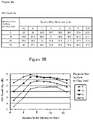
- Figures 9A and 9B are a data table and a graph showing the intensity of flaw echo at the time when an opening width is changed.
- Figure 9A is a data table of 80% sensitivity
- Figure 9B is a graph of 80% sensitivity.
- the abscissas represent the opening width
- the ordinates represent the 80% sensitivity.
- the data in the case where the opening width dimension is 12.5 mm are the data at the time when ultrasonic testing was performed without the installation of the vibration insulating member 4.
- the value of 80% sensitivity changes depending on the opening width dimension, and has a peak.
- Figures 10A and 10B are a data table and a graph showing the range of distance at which surface echo appears at the time when an opening width is changed.
- Figure 10A is a data table of 20%S echo distance
- Figure 10B is a graph of 20%S echo distance.
- the abscissas represent the opening width
- the ordinates represent the 20%S echo depth.
- the 20%S echo distance has a tendency of being shorter as the opening width dimension decreases.
- the opening width dimension corresponding to the distance from the test object surface to the target flaw was determined as described below.
- the opening width dimension corresponding to the distance from the test object surface to the target flaw was made an opening width dimension such that the 20%S echo distance was approximately at a minimum
- the opening width dimension corresponding to the distance from the test object surface to the target flaw was made an opening width dimension such that the peak intensity of flaw echo was approximately at a maximum, that is, the 80% sensitivity was approximately at a minimum.
- the opening width dimension corresponding to the distance from the test object surface to the target flaw was set at 6 mm in the case where the distance from the test object surface to the target flaw was 5 mm, was set at 6 mm in the case where the distance from the test object surface to the target flaw was 10 mm, was set at 8 mm in the case where the distance from the test object surface to the target flaw was 15 mm, and was set at 10 mm in the case where the distance from the test object surface to the target flaw was 20 mm.
- Ultrasonic testing was performed by installing the vibration insulating member 4 having the opening width dimension corresponding to the distance from the test object surface to the target flaw onto the transducer surface.
- the vibration insulating member 4 having the opening width dimension corresponding to the distance from the test object surface to the target flaw onto the transducer surface By installing the vibration insulating member 4 having the opening width dimension corresponding to the distance from the test object surface to the target flaw onto the transducer surface, the flaw echo of artificial flaw was not buried in surface echo, and the artificial flaw could be detected easily. Therefore, it can be anticipated that even in the ultrasonic testing of natural flaw, even for a flaw near the surface, flaw echo is made less liable to be buried in surface echo, and the flaw can be detected easily.
Landscapes
- Physics & Mathematics (AREA)
- Health & Medical Sciences (AREA)
- Life Sciences & Earth Sciences (AREA)
- Chemical & Material Sciences (AREA)
- Analytical Chemistry (AREA)
- Biochemistry (AREA)
- General Health & Medical Sciences (AREA)
- General Physics & Mathematics (AREA)
- Immunology (AREA)
- Pathology (AREA)
- Acoustics & Sound (AREA)
- Investigating Or Analyzing Materials By The Use Of Ultrasonic Waves (AREA)
Description
- The present invention relates to an ultrasonic testing method for performing flaw testing by using an ultrasonic array probe. More particularly, the invention relates to an ultrasonic testing method for facilitating detection of a flaw near a surface of a test object.
- Conventionally, there has been known an ultrasonic testing method using an ultrasonic array probe in which transducers are linearly arranged to detect a flaw in a wheel such as a railway wheel.
- Unfortunately, for a flaw existing near a surface of a test object, flaw echo is buried in surface echo, so that the detection of flaw may be difficult.
- Also, there has been an ultrasonic testing method for detecting a flaw near a surface by controlling the beam diameter of the ultrasonic beam of an ultrasonic array probe so that the beam diameter (d) and the in-water wavelength (λ0) of ultrasonic beam are 1/(d·λ0)≥1 (for example, refer to Patent Literature 1) to enhance the defect detectability (S/N). Unfortunately, also in such a method, for a flaw existing near a surface, flaw echo is buried in surface echo, so that the flaw may not be detected sufficiently.
Patent Literature 2 is directed to an ultrasonic diagnosis which is capable of switching an ultrasonic beam shape as needed by covering a part of a transmission-reception surface with the periphery of an opening. -
- [Patent Literature 1]
JP2003-4709A - [Patent Literature 2]
JP 11 206764 A - The present invention has been made to solve the above-described problems with the prior arts, and an object thereof is to provide an ultrasonic testing method capable of facilitating detection of a flaw existing near a surface of a test object.
- The present inventor conducted studies earnestly and obtained a finding that by installing a vibration insulating member having the configuration described below onto a transducer surface, the range of distance from the surface of test object in which surface echo appears is made narrow, and also the intensity of flaw echo is changed. Hereunder, this finding will be explained.
- The vibration insulating member was installed onto the transducer surface as described below.
- The vibration insulating member has an opening part, and the dimension of the width of opening part (hereinafter, referred also to as an opening part width) is smaller than the width dimension of the transducer surface. The vibration insulating member absorbs the vibrations of the transducer surface. Herein, the width of opening part refers to the size of opening part in the direction perpendicular to the arrangement direction of transducers in the state in which the vibration insulating member has been installed onto the transducer surface. Also, the width of transducer surface refers to the size of the transducer surface in the direction perpendicular to the arrangement direction of transducers.
- The vibration insulating member was installed so as to come into contact with the transducer surface of an ultrasonic array probe (hereinafter, referred also to as an array probe).
- In the state in which the vibration insulating member has been installed, a part of the transducer surface in the width direction of the transducer surface is exposed through the opening part. A portion exposed by the opening part of the transducer surface as described above is referred to as an exposed surface. Since the width of opening part is narrower than the width of transducer surface, the width of exposed surface is narrower than the width of the transducer surface.
- In the state in which the vibration insulating member had been installed onto the transducer surface, the vibration insulating member absorbed the vibrations of a region with which the vibration insulating member is in contact in the transducer surface.
-
Figure 1 is a schematic diagram showing the distributions of propagation time of surface echo in the case where the above-described vibration insulating member has been installed onto a transducer surface and in the case where the vibration insulating member has not been installed onto the transducer surface. The abscissas represent propagation time, and the ordinates represent the ratio of surface echo at each propagation time. - The distribution of propagation time of surface echo in the case where the vibration insulating member has been installed onto the transducer surface is narrowed to the short time side as compared with the case where the vibration insulating member has not been installed.
- The main reason why the distribution of propagation time of surface echo in the case where the vibration insulating member has been installed onto the transducer surface is narrowed to the short time side as described above as compared with the case where the vibration insulating member has not been installed is thought to be as described below.
-
Figures 2A and 2B are schematic views showing propagation paths of ultrasonic waves reflected by a surface of a test object, which are viewed from the transducer arrangement direction.Figure 2A is a schematic view showing propagation paths in the case where a vibration insulating member has not been installed onto a transducer surface, andFigure 2B is a schematic view showing propagation paths in the case where the vibration insulating member has been installed onto the transducer surface. - The length of a propagation path E through which the ultrasonic waves transmitted from a
transducer surface 111 of anarray probe 101 perpendicularly to asurface 121 of atest object 102 are reflected perpendicularly by thesurface 121 and return to thetransducer surface 111 is the same in the case where avibration insulating member 103 has not been installed and in the case where thevibration insulating member 103 has been installed. - However, as the propagation path through which the ultrasonic waves transmitted from a
transducer surface 111 perpendicularly to thesurface 121 of thetest object 102 are reflected by thesurface 121 and return to thetransducer surface 111, for example, in the case where thevibration insulating member 103 has not been installed, there is present a propagation path E1 through which the ultrasonic waves transmitted from one end side in the width direction of thetransducer surface 111 returns to the other end side in the width direction of thetransducer surface 111. This propagation path E1 is longer than a propagation path E2 through which the ultrasonic waves transmitted from one end side in the width direction of an exposedsurface 112 returns to the other end side in the width direction of the exposedsurface 112 in the case where thevibration insulating member 103 has been installed. - Therefore, the distribution of propagation distance through which the ultrasonic waves transmitted from the
transducer surface 111 are reflected by thesurface 121 of the test object and return to thetransducer surface 111 in the case where thevibration insulating member 103 has been installed is narrowed to the short distance side as compared with the case where thevibration insulating member 103 has not been installed. - Thus, the distribution of propagation time in the case where the
vibration insulating member 103 has been installed is narrowed to the short time side as compared with the case where thevibration insulating member 103 has not been installed. - In other words, the range of distance from the test object surface in which surface echo appears in the case where the
vibration insulating member 103 has been installed becomes easily narrower than that in the case where thevibration insulating member 103 has not been installed. - Next, the change in the intensity of flaw echo produced by the installation of the vibration insulating member onto the transducer surface will be explained.
- The present inventor obtained a finding that the intensity of flaw echo changes depending on the opening width dimension of the vibration insulating member, and the intensity becomes at a peak at a certain opening width dimension.
- The reason for this is thought to be as described below. The short distance sound field limit distance of transducer, in other words, the distance from the transducer at which the sound pressure of ultrasonic waves becomes at a maximum changes depending on the diameter of transducer in such a manner as being expressed by the publicly-known formula (X0=D2/4λ, Xo: short distance sound field limit distance, D: diameter of transducer, λ: wavelength in medium) in the case where the transducer is a circular transducer. For the array probe onto which the vibration insulating member is installed, it is thought that the short distance sound field limit distance changes depending on the width of exposed surface contributing to vibrations in the transducer surface, that is, the opening width dimension. Therefore, it is thought that the intensity of flaw echo becomes at a peak when the distance from the test object surface to a flaw in the test object and the short distance sound field limit distance at the opening width dimension of the installed vibration insulating member agree with each other.
- The present inventor obtained a finding that by installing the vibration insulating member having the opening part whose width is narrower than the width of the transducer surface so as to be in contact with the transducer surface as described above, vibrations of a region with which the vibration insulating member is in contact in the transducer surface are absorbed, and by narrowing the vibrating region to the exposed surface having a width narrower than the width of the transducer surface, the range of distance from the test object surface in which surface echo appears is made narrower than the range in the case where the vibration insulating member has not been installed. Also, the present inventor obtained a finding that the intensity of flaw echo changes depending on the opening width dimension of the vibration insulating member, and the intensity becomes at a peak at a certain opening width dimension.
- Considering both of the range of distance from the test object surface in which surface echo appears in the case where the vibration insulating member has been installed and the intensity of flaw echo, the opening width dimension of vibration insulating member at which a flaw is easily detected is determined in advance according to the distance from the test object surface to a target flaw. In ultrasonic testing, the ultrasonic testing is performed by installing the vibration insulating member having an opening width dimension corresponding to the distance from the test object surface to the target flaw onto the transducer surface. From this fact, the present inventor found that even for a flaw near the surface, flaw echo is less liable to be buried in surface echo, and the flaw can be detected easily.
- The present invention has been accomplished based on the above finding by the present inventors. That is, in order to solve the above-described problems, the present invention is as described in the attached claims.
- According to the present invention, by installing the vibration insulating member having the opening part whose width is narrower than the width of the transducer surface, the vibrations of the region that is in contact with the vibration insulating member in the transducer surface are absorbed, and the vibrating region is narrowed to the exposed surface having a width narrower than the width of the transducer surface. That is, by the vibration insulating member, the width of vibrating region is narrowed from the width of the transducer surface to the width of the exposed surface. Since the width of the exposed surface is narrower than the width of the transducer surface, the range of distance from the test object surface in which surface echo appears becomes narrower than that in the case where the vibration insulating member has not been installed.
- The opening width dimension corresponding to the distance from the test object surface to the target flaw is determined in advance, and when ultrasonic testing is performed, the ultrasonic testing is performed by installing the vibration insulating member having an opening width dimension corresponding to the distance from the test object surface to the target flaw.
- When the opening width dimension corresponding to the distance from the test object surface to the target flaw is determined, for ease of detection of the target flaw, the opening width dimension corresponding to the distance from the test object surface to the target flaw is determined in consideration of both of the range of distance from the test object surface in which surface echo appears and the intensity of flaw echo. Thereby, even for a flaw near the surface, flaw echo is made less liable to be buried in surface echo, and the flaw can be detected easily.
- In order to determine the opening width dimension corresponding to the distance from the test object surface to the target flaw so as to facilitate detection of the target flaw, for example, the following procedure has only to be carried out.
- A specimen provided with a plurality of artificial flaws each having a different distance from a specimen surface and a plurality of vibration insulating members each having a different opening width dimension are prepared, ultrasonic testing is performed by changing the plurality of vibration insulating members each having a different opening width dimension for individual artificial flaws, and the range of distance from the specimen surface in which surface echo appears and the intensity of flaw echo of artificial flaw are examined. Thus, the range of distance from the specimen surface in which surface echo appears and the data on the intensity of flaw echo of artificial flaw, for each distance from the specimen surface to an artificial flaw and for each opening width dimension of the vibration insulating member, are gotten together.
- Based on the range of distance from the specimen surface in which surface echo appears and the intensity of flaw echo of artificial flaw, the opening width dimension at which a flaw is easily detected is determined for each distance from the test object surface to the target flaw. In other words, the opening width dimension corresponding to the distance from the test object surface to the target flaw is determined. In order to determine the opening width dimension, for example, in the case where the position of target flaw is close to the test object surface, the opening width dimension such that the range of distance from the test object surface in which surface echo appears becomes approximately the narrowest has only to be determined, and in the case where the position of target flaw is far from the test object surface, the opening width dimension such that the intensity of flaw echo of the target flaw becomes approximately the highest has only to be determined.
- Also, in order to determine the opening width dimension corresponding to the distance from the test object surface to the target flaw, the opening width dimension may be determined so that the range of distance from the test object surface in which surface echo appears becomes approximately the narrowest over the whole distance, or the opening width dimension may be determined so that the intensity of flaw echo of the target flaw becomes approximately the highest.
- Thus, by performing ultrasonic testing by installing the vibration insulating member having the opening width dimension corresponding to the distance from the test object surface to the target flaw onto the transducer surface, even for a flaw near the surface, flaw echo is made less liable to be buried in surface echo, and the flaw can be detected easily.
- Also, since the vibration insulating member is detachable from the transducer surface, the vibration insulating member can be exchanged. Therefore, even in the case where the distances from the test object surface to the plurality of target flaws are different, the vibration insulating member having the opening width dimension corresponding to the distance from the test object surface to each target flaw is selected and installed onto the array probe body, whereby a flaw can be detected by using a single array probe.
- According to the present invention, a flaw near the surface of test object can be detected easily.
-
-
Figure 1 is a schematic diagram showing the distributions of propagation time of surface echo in the case where a vibration insulating member has been installed onto a transducer surface and in the case where the vibration insulating member has not been installed onto the transducer surface. -
Figures 2A and 2B are schematic views showing propagation paths of ultrasonic waves reflected by a surface of a test object, which are viewed from the transducer arrangement direction.Figure 2A is a schematic view showing propagation paths in the case where a vibration insulating member has not been installed onto a transducer surface, andFigure 2B is a schematic view showing propagation paths in the case where the vibration insulating member has been installed onto the transducer surface. -
Figure 3 is a configuration diagram for explaining one example of an ultrasonic testing apparatus used for the ultrasonic testing method in accordance with an embodiment of the present invention. -
Figures 4A to 4D are views showing the configuration of an array probe.Figure 4A is a perspective view of the array probe,Figure 4B is an exploded perspective view of the array probe,Figure 4C is a front view of the array probe, which is viewed from the normal direction of a transducer surface of the array probe, andFigure 4D is a plan view of the array probe. -
Figure 5 is a diagram showing an A scope at the time when ultrasonic testing is performed on a test object provided with an artificial flaw. -
Figure 6 is an exploded perspective view of an array probe using two columnar vibration insulating members. -
Figure 7 is a construction view of an Fe stepped test specimen. -
Figure 8 is a diagram for explaining a method for evaluating the intensity of flaw echo and a method for evaluating the range of distance from a test object surface in which surface echo appears. -
Figures 9A and 9B are a data table and a graph showing the intensity of flaw echo at the time when an opening width is changed.Figure 9A is a data table of 80% sensitivity, andFigure 9B is a graph of 80% sensitivity. -
Figures 10A and 10B are a data table and a graph showing the range of distance at which surface echo appears at the time when an opening width is changed.Figure 10A is a data table of 20%S echo distance, andFigure 10B is a graph of 20%S echo distance. - The ultrasonic testing method in accordance with an embodiment of the present invention will now be described with reference to the accompanied drawings as appropriate.
-
Figure 3 is a configuration diagram for explaining one example of an ultrasonic testing apparatus used for the ultrasonic testing method in accordance with this embodiment. - An
ultrasonic testing apparatus 1 is provided with an ultrasonic array probe (hereinafter, referred also to as an array probe) 3 for testing awheel 2. Thearray probe 3 is arranged so as to face a tested portion of thewheel 2. - Also, the
ultrasonic testing apparatus 1 is provided with anarray flaw detector 11 performing functions of transmitting a transmission/reception control signal to thearray probe 3, amplifying the signal received from thearray probe 3, and the like; apersonal computer 12 performing functions of setting various parameters for thearray flaw detector 11, preparing images of an A scope, a B scope, and the like by receiving a signal from thearray flaw detector 11, and the like; acontrol panel 14 for giving a rotation signal and the like to arotary driving section 13, described later; therotary driving section 13 for rotating thewheel 2 to perform testing on the entire circumference of thewheel 2; and atank 15 for immersing thewheel 2 and thearray probe 3 in water. -
Figures 4A to 4D are views showing the configuration of thearray probe 3.Figure 4A is a perspective view of thearray probe 3,Figure 4B is an exploded perspective view of thearray probe 3,Figure 4C is a front view of thearray probe 3, which is viewed from the normal direction of a transducer surface of thearray probe 3, andFigure 4D is a plan view of thearray probe 3. - The
array probe 3 is provided with an ultrasonic array probe body (hereinafter, referred also to as an array probe body) 32 having a plurality oftransducers 31 linearly arranged. The surface of thearray probe body 32 for transmitting ultrasonic waves from thetransducers 31 is referred to as atransducer surface 33. - The
array probe 3 is provided with avibration insulating member 4 that is installed onto thetransducer surface 33 to absorb the vibrations of thetransducer surface 33, and aninstallation frame 5 for installing thevibration insulating member 4. - The material of the
vibration insulating member 4 is, for example, rubber, resin, or cork; however, it may be any material that absorbs the vibrations of thetransducer surface 33. - The
vibration insulating member 4 has anopening part 41, and the width dimension of theopening part 41 is smaller than the width dimension of thetransducer surface 33. The openingpart 41 has a rectangular shape extending in the arrangement direction of thetransducers 31. The width of theopening part 41 refers to the size of theopening part 41 in the direction perpendicular to the arrangement direction oftransducers 31 in the state in which thevibration insulating member 4 has been installed onto thetransducer surface 33. Also, the width of thetransducer surface 33 refers to the size of the transducer surface in the direction perpendicular to the arrangement direction oftransducers 31. - The
vibration insulating member 4 is installed by using theinstallation frame 5 so as to be in contact with thetransducer surface 33. - In the state in which the
vibration insulating member 4 has been installed, a part of the transducer surface in the width direction of thetransducer surface 33 is exposed through the openingpart 41. A portion exposed by the openingpart 41 of the transducer surface as described above is referred to as an exposedsurface 34. Since the width of theopening part 41 is narrower than the width of the transducer surface, the width of the exposedsurface 34 is narrower than the width of the transducer surface. - In the state of having been installed onto the
transducer surface 33, thevibration insulating member 4 absorbs the vibrations of the region with which thevibration insulating member 4 is in contact in thetransducer surface 33. - The
installation frame 5 is provided with fixingparts 51 for fixing thevibration insulating member 4 to thetransducer surface 33, andside surface parts 52 butting against the side surfaces of thearray probe body 32, the side surfaces being perpendicular to the transducer arrangement direction, and in each of theside surface parts 52, a threadedhole 53 penetrating theside surface part 52 is provided. - In order to install the
vibration insulating member 4 onto thetransducer surface 33, thevibration insulating member 4 is disposed so as to be in contact with thetransducer surface 33, and thevibration insulating member 4 is fixed to thetransducer surface 33 by the fixingparts 51 of theinstallation frame 5. Then, screws 54 are screwed into the threadedholes 53 to mount theinstallation frame 5. - Thus, the
vibration insulating member 4 is detachably installed onto thetransducer surface 33. - The ultrasonic testing method is carried out as described below.
- The
vibration insulating member 4 having the opening width dimension corresponding to the distance from the test object surface to the target flaw is installed onto thetransducer surface 33 of thearray probe body 32 by using theinstallation frame 5. - Then, the
array probe 3 is disposed so that thetransducer surface 33 faces the tested portion of thewheel 2, and water, which serves as a coupling medium, is put into thetank 15 so that thewheel 2 and thearray probe 3 are immersed. As the coupling medium, oil or the like can also be used. From thepersonal computer 12, the testing conditions such as the intensity of ultrasonic waves transmitted from thearray probe 3 and the scanning speed are transmitted to thearray flaw detector 11, and the testing conditions are converted into the transmission/reception control signal by thearray flaw detector 11 and are transmitted to thearray probe 3. Thearray probe 3 transmits ultrasonic waves to the tested portion of thewheel 2, receives reflection echo, and transmits the signal corresponding to the received reflection echo to thearray flaw detector 11. Thearray flaw detector 11 amplifies the signal received from thearray probe 3 and transmits it to thepersonal computer 12. Thepersonal computer 12 displays the image of A scope, B scope, or the like. Also, a rotation signal is transmitted from thepersonal computer 12 to therotary driving section 13 via thecontrol panel 14, whereby thewheel 2 is rotated, so that the entire circumference of thewheel 2 can be tested. By doing this, the flaw detection of thewheel 2 can be carried out. Thus, the ultrasonic testing method includes a step of performing ultrasonic testing by installing thevibration insulating member 4 having the opening width dimension corresponding to the distance from the test object surface to the target flaw onto thetransducer surface 33 of thearray probe body 32 and by radiating ultrasonic waves from thetransducer surface 33 onto the surface of test object. - The transmission and reception of ultrasonic waves from the
array probe 3 are accomplished, for example, by a linear scan or a steering scan. The linear scan is a method in which sometransducers 31 constituting thearray probe 3 are made one transmission unit; when ultrasonic waves are transmitted in the one transmission unit, the ultrasonic waves are transmitted so that the ultrasonic waves sent from eachtransducer 31 are in parallel with each other, or so that the ultrasonic waves sent from eachtransducer 31 are concentrated on one point by shifting the timing of transmission of eachtransducer 31; and in this state, the ultrasonic waves are parallel-scanned by controlling thearray probe 3 by using the transmission/reception control signal sent from thearray flaw detector 4 so that the transmission unit is shifted successively along the arrangement direction of thetransducer 31. The steering scan is a method in which sometransducers 31 constituting thearray probe 3 are made one transmission unit; when ultrasonic waves are transmitted in the one transmission unit, the ultrasonic waves are transmitted so that the ultrasonic waves sent from eachtransducer 31 are in parallel with each other, or so that the ultrasonic waves sent from eachtransducer 31 are concentrated on one point by shifting the timing of transmission of eachtransducer 31; and in this state, scanning is performed by changing the exit angle. - Next, the installation of the
vibration insulating member 4 onto thetransducer surface 33, which is a feature of this embodiment, will be explained. -
Figure 5 is a diagram showing an A scope at the time when ultrasonic testing is performed on a test object provided with an artificial flaw. The abscissas represent propagation time of ultrasonic waves, showing the distance from the surface of test object, and the ordinates represent the intensity of echo. - The test object for which this A scope has been picked up is provided with an artificial flaw formed perpendicularly toward the incident surface which ultrasonic waves enter from the surface on the opposite side of the incident surface. The flaw echo of the front end of artificial flaw is detected by the A scope. Also, on the A scope, the surface echo of the incident surface and the shape echo of the surface on the opposite side of the incident surface appear.
- The surface echo appears from the position of the surface of test object, and decreases as the distance from the test object surface increases. In the case where a flaw is present near the surface of test object, and the intensity of flaw echo is low, the flaw echo is buried in the surface echo, and the flaw cannot be detected.
- Therefore, it is desirable that the range of distance from the test object surface in which surface echo appears is as narrow as possible, and it is desirable that flaw echo appears so that the intensity thereof is as high as possible.
- In this embodiment, by installing the
vibration insulating member 4 onto thetransducer surface 33 to decrease the width dimension of the exposedsurface 34, the range of distance from the test object surface in which surface echo appears is made narrow, and by changing the intensity of flaw echo, a flaw is made easy to detect. - Specifically, the opening width dimension of vibration insulating member at which a flaw is easily detected is determined in advance according to the distance from the test object surface to the target flaw, and when ultrasonic testing is performed, the ultrasonic testing is performed by installing the vibration insulating member having an opening width dimension corresponding to the distance from the test object surface to the target flaw.
- In the case where the opening width dimension corresponding to the distance from the test object surface to the target flaw, if the opening width dimension is determined according to the distance from the test object surface to the target flaw considering both of the range of distance from the test object surface in which surface echo appears and the intensity of flaw echo so that the target flaw can be detected easily, even for a flaw near the surface, flaw echo is less liable to be buried in surface echo, and the flaw can be detected easily.
- In order to determine the opening width dimension corresponding to the distance from the test object surface to the target flaw so that the target flaw can be detected easily, for example, the following procedure has only to be carried out.
- A specimen provided with a plurality of artificial flaws each having a different distance from the specimen surface and a plurality of
vibration insulating members 4 each having a different opening width dimension are prepared, ultrasonic testing is performed by changing the plurality ofvibration insulating members 4 each having a different opening width dimension for individual artificial flaws, and the range of distance from the specimen surface in which surface echo appears and the intensity of flaw echo of artificial flaw are examined. Thus, the range of distance from the specimen surface in which surface echo appears and the data on the intensity of flaw echo of artificial flaw, for each distance from the specimen surface to an artificial flaw and for each opening width dimension of the vibration insulating member, are gotten together. - Based on the range of distance from the specimen surface in which surface echo appears and the intensity of flaw echo of artificial flaw, the opening width dimension at which a flaw is easily detected is determined for each distance from the test object surface to the target flaw. In other words, the opening width dimension corresponding to the distance from the test object surface to the target flaw is determined. In order to determine the opening width dimension, for example, in the case where the position of target flaw is close to the test object surface, the opening width dimension such that the range of distance from the test object surface in which surface echo appears becomes approximately the narrowest has only to be determined, and in the case where the position of target flaw is far from the test object surface, the opening width dimension such that the intensity of flaw echo of the target flaw becomes approximately the highest has only to be determined.
- Also, in order to determine the opening width dimension corresponding to the distance from the test object surface to the target flaw, the opening width dimension may be determined so that the range of distance from the test object surface in which surface echo appears becomes approximately the narrowest over the whole distance, or the opening width dimension may be determined so that the intensity of flaw echo of the target flaw becomes approximately the highest.
- Thus, by performing ultrasonic testing by installing the
vibration insulating member 4 having the opening width dimension corresponding to the distance from the test object surface to the target flaw onto the transducer surface, even for a flaw near the surface, flaw echo is made less liable to be buried in surface echo, and the flaw can be detected easily. - In particular, this procedure is effective in detecting a flaw such that the distance from the test object surface is within 40 mm, and further this distance is within 10 mm.
- Also, since the vibration insulating member is detachable from the transducer surface, the vibration insulating member can be exchanged. Therefore, even in the case where the distances from the test object surface to the plurality of target flaws are different, the vibration insulating member having the opening width dimension corresponding to the distance from the test object surface to each target flaw is selected and installed onto the array probe body, whereby a flaw can be detected by using a single array probe.
- In the above-described embodiment, the shape of the
opening part 41 has been made rectangular; however, the shape of theopening part 41 is not limited to a rectangular shape, and may be, for example, an oval shape or a trapezoidal shape. - Also, the shape of the
vibration insulating member 4 is not limited to the above-described shape, and may be any shape such that the width dimension of the exposedsurface 34 is made small. - For example, two columnar vibration insulating members extending in the arrangement direction of
transducers 31 may be used. -
Figure 6 is an exploded perspective view of anarray probe 3 using two columnar vibration insulating members. - The two columnar vibration insulating members 4a are arranged on both end sides in the width direction of the
transducer surface 33, and are installed by theinstallation frame 5. The width of the exposedsurface 34 in this case is the distance between the two vibration insulating members 4a. - Even in the case where such two columnar vibration insulating members 4a are installed, the effect same as that in the case where the
vibration insulating member 4 having the openingpart 41 is installed can be achieved. - Next, a working example of ultrasonic testing method will be explained.
- Ultrasonic testing was performed by using the
ultrasonic testing apparatus 1 same as that shown inFigure 3 and by mounting a test object for testing in place of thewheel 2. - In the testing, there was used the
array probe body 32 in which one hundred and twenty-eighttransducers 31 each having a length in the arrangement direction of 0.85 mm were linearly arranged at a pitch of 1 mm, and the width of thetransducer surface 33 was 12.5 mm. The oscillation frequency of thetransducer 31 was 5 MHz. - Seven foamed rubber-made
vibration insulating members 4 each having an opening width of 4.5 mm, 6 mm, 7 mm, 8 mm, 9 mm, 10 mm, and 11 mm, respectively, were prepared, and ultrasonic testing was performed by installing each of thesevibration insulating members 4 successively and exchangedly onto thetransducer surface 33 of thearray probe body 32 by using theinstallation frame 5. The thickness of thevibration insulating member 4 was set at 2 mm, and the length in the transducer arrangement direction of theopening part 41 was made longer than the arrangement length of the arrangedtransducers 31. - The ultrasonic testing was performed by a linear scan with one oscillation unit being 16.
- As the
array flaw detector 11, a portable phased array ultrasonic flaw detector "PAL2" manufactured by Japan Clout Kramer Co. Ltd. was used. - As the test object, an Fe stepped test specimen was used.
-
Figure 7 is a construction view of the Fe stepped test specimen. - In the Fe stepped test specimen, artificial flaws each consisting of a 1.19 mm-diameter flat bottomed hole were formed perpendicularly toward the incident surface which ultrasonic waves enter from the surfaces on the opposite side of the incident surface. The distance from the incident surface to the front end of each artificial flaw was made of four steps of 5 mm, 10 mm, 15 mm, and 20 mm.
-
Figure 8 is a diagram for explaining a method for evaluating the intensity of flaw echo and a method for evaluating the range of distance from a test object surface in which surface echo appears. - The intensity of flaw echo was evaluated as described below: the sensitivity of the
array flaw detector 11 was controlled so that the peak intensity of flaw echo was 80% of full scale of the intensity on the A scope, and evaluation was done by the sensitivity (dB) at that time (hereinafter, this sensitivity is referred to as an 80% sensitivity). It is shown that as the value of 80% sensitivity decreases, the peak intensity of flaw echo appears greatly. - The range of distance from the test object surface in which surface echo appears was evaluated by the distance from the test object surface at the time when the intensity of surface echo at the time when the sensitivity of the
array flaw detector 11 was controlled to the 80% sensitivity decreased to 20% of full scale of the intensity on the A scope (hereinafter, referred to as a 20%S echo distance). - In this working example, the range of distance from the test object surface in which surface echo appears was evaluated by controlling the sensitivity of array flaw detector to the 80% sensitivity; however, the evaluation may be done by making the sensitivity of array flaw detector the same.
-
Figures 9A and 9B are a data table and a graph showing the intensity of flaw echo at the time when an opening width is changed.Figure 9A is a data table of 80% sensitivity, andFigure 9B is a graph of 80% sensitivity. InFigure 9B , the abscissas represent the opening width, and the ordinates represent the 80% sensitivity. The data in the case where the opening width dimension is 12.5 mm are the data at the time when ultrasonic testing was performed without the installation of thevibration insulating member 4. - In each of data in which the distance from the test object surface to a flaw is different, the value of 80% sensitivity changes depending on the opening width dimension, and has a peak.
-
Figures 10A and 10B are a data table and a graph showing the range of distance at which surface echo appears at the time when an opening width is changed.Figure 10A is a data table of 20%S echo distance, andFigure 10B is a graph of 20%S echo distance. InFigure 10B , the abscissas represent the opening width, and the ordinates represent the 20%S echo depth. - In the case where the value of 80% sensitivity is in the same degree, the 20%S echo distance has a tendency of being shorter as the opening width dimension decreases.
- Based on the above-described data, the opening width dimension corresponding to the distance from the test object surface to the target flaw was determined as described below.
- In the case where the distance from the test object surface to the target flaw was 10 mm or shorter, the opening width dimension corresponding to the distance from the test object surface to the target flaw was made an opening width dimension such that the 20%S echo distance was approximately at a minimum, and in the case where the distance from the test object surface to the target flaw exceeded 10 mm, the opening width dimension corresponding to the distance from the test object surface to the target flaw was made an opening width dimension such that the peak intensity of flaw echo was approximately at a maximum, that is, the 80% sensitivity was approximately at a minimum.
- From the above-described test results, the opening width dimension corresponding to the distance from the test object surface to the target flaw was set at 6 mm in the case where the distance from the test object surface to the target flaw was 5 mm, was set at 6 mm in the case where the distance from the test object surface to the target flaw was 10 mm, was set at 8 mm in the case where the distance from the test object surface to the target flaw was 15 mm, and was set at 10 mm in the case where the distance from the test object surface to the target flaw was 20 mm.
- Ultrasonic testing was performed by installing the
vibration insulating member 4 having the opening width dimension corresponding to the distance from the test object surface to the target flaw onto the transducer surface. - By installing the
vibration insulating member 4 having the opening width dimension corresponding to the distance from the test object surface to the target flaw onto the transducer surface, the flaw echo of artificial flaw was not buried in surface echo, and the artificial flaw could be detected easily. Therefore, it can be anticipated that even in the ultrasonic testing of natural flaw, even for a flaw near the surface, flaw echo is made less liable to be buried in surface echo, and the flaw can be detected easily. -
- 3
- array probe
- 31
- transducer
- 32
- array probe body
- 33
- transducer surface
- 4
- vibration insulating member
- 41
- opening part
Claims (4)
- An ultrasonic testing method comprising a step of performing ultrasonic testing bydetachably installing a vibration insulating member (4), which has an opening part (41) whose width is narrower than a width of a transducer surface (33) of an ultrasonic array probe body (32) having transducers (31) linearly arranged, and which absorbs vibrations of the transducer surface, onto the transducer surface so that a part of the transducer surface (33) in the width direction of the transducer surface is exposed through the opening part and a non-exposed part of the transducer surface is in contact with the vibration insulating member, and byradiating ultrasonic waves from the transducer surface onto a surface of a test object, whereinthe width dimension of the opening part (41) is determined in advance according to a distance from a surface of the test object to a target flaw positioned near the surface of the test object,determining of the width dimension of the opening part (41) comprises:providing a specimen with a plurality of artificial flaws each having a different distance from a specimen surface;preparing a plurality of vibration insulating members each having a different opening width dimension;performing ultrasonic testing by changing the plurality of vibration insulating members each having a different opening width dimension for individual artificial flaws;examining a range of distance from the specimen surface in which a surface echo appears, and examining an intensity of flaw echo of the respective artificial flaw, wherein the range of distance from the specimen surface in which surface echo appears and the data on the intensity of flaw echo of artificial flaw, for each distance from the specimen surface to the artificial flaw and for each opening width dimension of the vibration insulating member, are gotten together; and
determining the opening width dimension at which a flaw is easily detected based on the range of distance from the specimen surface in which the surface echo appears, and on the intensity of the flaw echo. - The ultrasonic testing method according to claim 1, wherein the distance of the flaw from the test object surface is within 40 mm.
- The ultrasonic testing method according to any one of the preceding claims, wherein the shape of the opening part (41) is rectangular, oval or trapezoidal.
- The ultrasonic testing method according to any one of the claims 1 to 2, wherein two columnar vibration insulating members (4) extending in an arrangement direction of the transducers (31) are used.
Applications Claiming Priority (2)
| Application Number | Priority Date | Filing Date | Title |
|---|---|---|---|
| JP2011138535 | 2011-06-22 | ||
| PCT/JP2012/064434 WO2012176613A1 (en) | 2011-06-22 | 2012-06-05 | Ultrasonic flaw detection method and ultrasonic array probe |
Publications (3)
| Publication Number | Publication Date |
|---|---|
| EP2728347A1 EP2728347A1 (en) | 2014-05-07 |
| EP2728347A4 EP2728347A4 (en) | 2015-11-04 |
| EP2728347B1 true EP2728347B1 (en) | 2022-08-03 |
Family
ID=47422453
Family Applications (1)
| Application Number | Title | Priority Date | Filing Date |
|---|---|---|---|
| EP12802866.9A Active EP2728347B1 (en) | 2011-06-22 | 2012-06-05 | Ultrasonic flaw detection method and ultrasonic array probe |
Country Status (9)
| Country | Link |
|---|---|
| US (1) | US9389206B2 (en) |
| EP (1) | EP2728347B1 (en) |
| JP (1) | JP5618223B2 (en) |
| CN (1) | CN103765206B (en) |
| AU (1) | AU2012274665B2 (en) |
| CA (1) | CA2839661C (en) |
| ES (1) | ES2924913T3 (en) |
| IN (1) | IN2014DN00124A (en) |
| WO (1) | WO2012176613A1 (en) |
Families Citing this family (5)
| Publication number | Priority date | Publication date | Assignee | Title |
|---|---|---|---|---|
| US10018613B2 (en) | 2006-11-16 | 2018-07-10 | General Electric Company | Sensing system and method for analyzing a fluid at an industrial site |
| US10578589B2 (en) * | 2017-06-01 | 2020-03-03 | Olympus Scientific Solutions Americas Inc. | System and method for ultrasound inspection with time reversal |
| CN108534721B (en) * | 2018-04-13 | 2020-10-23 | 沈阳工业大学 | Square pipeline external detection electromagnetic ultrasonic thickness measuring transducer structure |
| CN108535365B (en) * | 2018-04-13 | 2020-10-23 | 沈阳工业大学 | Square pipeline external detection electromagnetic ultrasonic flaw detection transducer structure |
| US11175263B2 (en) * | 2020-02-24 | 2021-11-16 | King Fahd University Of Petroleum And Minerals | Apparatus and method for generating, measuring, and evaluating vibrational modes in cylindrical objects |
Family Cites Families (9)
| Publication number | Priority date | Publication date | Assignee | Title |
|---|---|---|---|---|
| US2320947A (en) * | 1942-01-24 | 1943-06-01 | American Bosch Corp | Fastening means |
| US5602336A (en) * | 1993-11-12 | 1997-02-11 | Tokimec Inc. | Flow detection apparatus employing tire probes having ultrasonic oscilators mounted therein |
| JPH08173433A (en) | 1994-12-22 | 1996-07-09 | Shimadzu Corp | Ultrasonic diagnostic device |
| JPH1062396A (en) | 1996-08-21 | 1998-03-06 | Furuno Electric Co Ltd | Ultrasonic scanning device, ultrasonic diagnostic device, nondestructive inspecting device, and ultrasonic oscillator array |
| JPH11206764A (en) | 1998-01-20 | 1999-08-03 | Aloka Co Ltd | Ultrasonic wave probe |
| JP4477171B2 (en) | 1999-10-05 | 2010-06-09 | 株式会社島津製作所 | Ultrasonic diagnostic equipment |
| JP2003004709A (en) | 2001-06-22 | 2003-01-08 | Sumitomo Metal Ind Ltd | Ultrasonic inspection method for wheel and apparatus therefor |
| WO2010101104A1 (en) | 2009-03-04 | 2010-09-10 | 株式会社 日立メディコ | Ultrasonic transmitting/receiving circuit and ultrasonic diagnostic device |
| US8438928B2 (en) * | 2010-05-17 | 2013-05-14 | Structural Integrity Associates, Inc. | Apparatus and method for non-destructive testing using ultrasonic phased array |
-
2012
- 2012-06-05 CA CA2839661A patent/CA2839661C/en active Active
- 2012-06-05 AU AU2012274665A patent/AU2012274665B2/en active Active
- 2012-06-05 EP EP12802866.9A patent/EP2728347B1/en active Active
- 2012-06-05 CN CN201280040775.0A patent/CN103765206B/en active Active
- 2012-06-05 US US14/128,661 patent/US9389206B2/en active Active
- 2012-06-05 ES ES12802866T patent/ES2924913T3/en active Active
- 2012-06-05 JP JP2013521519A patent/JP5618223B2/en active Active
- 2012-06-05 WO PCT/JP2012/064434 patent/WO2012176613A1/en active Application Filing
- 2012-06-05 IN IN124DEN2014 patent/IN2014DN00124A/en unknown
Also Published As
| Publication number | Publication date |
|---|---|
| WO2012176613A1 (en) | 2012-12-27 |
| IN2014DN00124A (en) | 2015-05-22 |
| EP2728347A1 (en) | 2014-05-07 |
| CN103765206B (en) | 2016-03-09 |
| EP2728347A4 (en) | 2015-11-04 |
| CN103765206A (en) | 2014-04-30 |
| CA2839661C (en) | 2017-01-24 |
| US9389206B2 (en) | 2016-07-12 |
| ES2924913T3 (en) | 2022-10-11 |
| AU2012274665A1 (en) | 2014-01-30 |
| CA2839661A1 (en) | 2012-12-27 |
| JP5618223B2 (en) | 2014-11-05 |
| JPWO2012176613A1 (en) | 2015-02-23 |
| AU2012274665B2 (en) | 2015-05-28 |
| US20140202250A1 (en) | 2014-07-24 |
Similar Documents
| Publication | Publication Date | Title |
|---|---|---|
| EP2728347B1 (en) | Ultrasonic flaw detection method and ultrasonic array probe | |
| US8286488B2 (en) | Apparatus and system for measuring material thickness | |
| JP2009524803A (en) | Non-destructive inspection method for subject having at least one acoustic anisotropic material region | |
| US20160116442A1 (en) | Destruction-free and contactless inspection method and inspection apparatus for surfaces of components with ultrasound waves | |
| Jäger et al. | Non-contact ultrasound with optimum electronic steering angle to excite Lamb waves in thin metal sheets for mechanical stress measurements | |
| US7821645B2 (en) | Microstructural feature and material property monitoring device for metallic material | |
| US20110179873A1 (en) | Apparatus for the non-destructive testing of samples using ultrasonic waves | |
| US20110126628A1 (en) | Non-destructive ultrasound inspection with coupling check | |
| JP5345096B2 (en) | Array ultrasonic flaw detector | |
| AU3274299A (en) | Method and apparatus for ultrasonic flaw detection | |
| Fromme et al. | Remote Monitoring of Plate‐Like Structures Using Guided Wave Arrays | |
| KR101113095B1 (en) | Ultrasonic measuring apparatus for nondestructive inspection | |
| WO2017122346A1 (en) | Ultrasonic measuring device | |
| KR20120015027A (en) | Longitudinal wave transducer wedge to maintain couplant layer and longitudinal wave transducer using the same | |
| Margetan et al. | Ultrasonic signal attenuation in engine titanium alloys | |
| JPH1151917A (en) | Tire type array probe and measuring device | |
| Uchida et al. | Availability study of a phased array ultrasonic technique | |
| Leleux et al. | NDT process using Lamb waves generated/detected by ultrasonic phased array probes for the defect detection in metallic and composite plates | |
| CA2330662C (en) | Method and apparatus for ultrasonic flaw detection | |
| JP6513771B2 (en) | Ultrasonic testing equipment for round bars | |
| Cawlev et al. | An EMAT array for the rapid inspection of large structures using guided waves | |
| JPS59122944A (en) | Probe and ultrasonic wave flaw detecting method | |
| Frome et al. | Development of a Permanently Attached Guided Wave Array for the Monitoring of Structural Integrity | |
| Fomme et al. | Development of a permanently attached guided ultrasonic waves array for structural integrity monitoring | |
| Wilcox et al. | Rapid imaging of large steel plate structures using guided waves |
Legal Events
| Date | Code | Title | Description |
|---|---|---|---|
| PUAI | Public reference made under article 153(3) epc to a published international application that has entered the european phase |
Free format text: ORIGINAL CODE: 0009012 |
|
| 17P | Request for examination filed |
Effective date: 20140120 |
|
| AK | Designated contracting states |
Kind code of ref document: A1 Designated state(s): AL AT BE BG CH CY CZ DE DK EE ES FI FR GB GR HR HU IE IS IT LI LT LU LV MC MK MT NL NO PL PT RO RS SE SI SK SM TR |
|
| DAX | Request for extension of the european patent (deleted) | ||
| RA4 | Supplementary search report drawn up and despatched (corrected) |
Effective date: 20151007 |
|
| RIC1 | Information provided on ipc code assigned before grant |
Ipc: G01N 29/24 20060101ALI20151001BHEP Ipc: G01N 29/04 20060101AFI20151001BHEP Ipc: G01N 29/22 20060101ALI20151001BHEP Ipc: G01N 29/07 20060101ALI20151001BHEP Ipc: G01N 29/32 20060101ALI20151001BHEP |
|
| STAA | Information on the status of an ep patent application or granted ep patent |
Free format text: STATUS: EXAMINATION IS IN PROGRESS |
|
| 17Q | First examination report despatched |
Effective date: 20181016 |
|
| STAA | Information on the status of an ep patent application or granted ep patent |
Free format text: STATUS: EXAMINATION IS IN PROGRESS |
|
| RAP1 | Party data changed (applicant data changed or rights of an application transferred) |
Owner name: NIPPON STEEL CORPORATION |
|
| GRAP | Despatch of communication of intention to grant a patent |
Free format text: ORIGINAL CODE: EPIDOSNIGR1 |
|
| STAA | Information on the status of an ep patent application or granted ep patent |
Free format text: STATUS: GRANT OF PATENT IS INTENDED |
|
| INTG | Intention to grant announced |
Effective date: 20220405 |
|
| GRAS | Grant fee paid |
Free format text: ORIGINAL CODE: EPIDOSNIGR3 |
|
| GRAA | (expected) grant |
Free format text: ORIGINAL CODE: 0009210 |
|
| STAA | Information on the status of an ep patent application or granted ep patent |
Free format text: STATUS: THE PATENT HAS BEEN GRANTED |
|
| AK | Designated contracting states |
Kind code of ref document: B1 Designated state(s): AL AT BE BG CH CY CZ DE DK EE ES FI FR GB GR HR HU IE IS IT LI LT LU LV MC MK MT NL NO PL PT RO RS SE SI SK SM TR |
|
| REG | Reference to a national code |
Ref country code: AT Ref legal event code: REF Ref document number: 1509136 Country of ref document: AT Kind code of ref document: T Effective date: 20220815 Ref country code: CH Ref legal event code: EP |
|
| REG | Reference to a national code |
Ref country code: DE Ref legal event code: R096 Ref document number: 602012078561 Country of ref document: DE |
|
| REG | Reference to a national code |
Ref country code: IE Ref legal event code: FG4D |
|
| REG | Reference to a national code |
Ref country code: ES Ref legal event code: FG2A Ref document number: 2924913 Country of ref document: ES Kind code of ref document: T3 Effective date: 20221011 |
|
| REG | Reference to a national code |
Ref country code: LT Ref legal event code: MG9D |
|
| REG | Reference to a national code |
Ref country code: NL Ref legal event code: MP Effective date: 20220803 |
|
| PG25 | Lapsed in a contracting state [announced via postgrant information from national office to epo] |
Ref country code: SE Free format text: LAPSE BECAUSE OF FAILURE TO SUBMIT A TRANSLATION OF THE DESCRIPTION OR TO PAY THE FEE WITHIN THE PRESCRIBED TIME-LIMIT Effective date: 20220803 Ref country code: RS Free format text: LAPSE BECAUSE OF FAILURE TO SUBMIT A TRANSLATION OF THE DESCRIPTION OR TO PAY THE FEE WITHIN THE PRESCRIBED TIME-LIMIT Effective date: 20220803 Ref country code: PT Free format text: LAPSE BECAUSE OF FAILURE TO SUBMIT A TRANSLATION OF THE DESCRIPTION OR TO PAY THE FEE WITHIN THE PRESCRIBED TIME-LIMIT Effective date: 20221205 Ref country code: NO Free format text: LAPSE BECAUSE OF FAILURE TO SUBMIT A TRANSLATION OF THE DESCRIPTION OR TO PAY THE FEE WITHIN THE PRESCRIBED TIME-LIMIT Effective date: 20221103 Ref country code: NL Free format text: LAPSE BECAUSE OF FAILURE TO SUBMIT A TRANSLATION OF THE DESCRIPTION OR TO PAY THE FEE WITHIN THE PRESCRIBED TIME-LIMIT Effective date: 20220803 Ref country code: LV Free format text: LAPSE BECAUSE OF FAILURE TO SUBMIT A TRANSLATION OF THE DESCRIPTION OR TO PAY THE FEE WITHIN THE PRESCRIBED TIME-LIMIT Effective date: 20220803 Ref country code: LT Free format text: LAPSE BECAUSE OF FAILURE TO SUBMIT A TRANSLATION OF THE DESCRIPTION OR TO PAY THE FEE WITHIN THE PRESCRIBED TIME-LIMIT Effective date: 20220803 Ref country code: FI Free format text: LAPSE BECAUSE OF FAILURE TO SUBMIT A TRANSLATION OF THE DESCRIPTION OR TO PAY THE FEE WITHIN THE PRESCRIBED TIME-LIMIT Effective date: 20220803 |
|
| REG | Reference to a national code |
Ref country code: AT Ref legal event code: MK05 Ref document number: 1509136 Country of ref document: AT Kind code of ref document: T Effective date: 20220803 |
|
| PG25 | Lapsed in a contracting state [announced via postgrant information from national office to epo] |
Ref country code: PL Free format text: LAPSE BECAUSE OF FAILURE TO SUBMIT A TRANSLATION OF THE DESCRIPTION OR TO PAY THE FEE WITHIN THE PRESCRIBED TIME-LIMIT Effective date: 20220803 Ref country code: IS Free format text: LAPSE BECAUSE OF FAILURE TO SUBMIT A TRANSLATION OF THE DESCRIPTION OR TO PAY THE FEE WITHIN THE PRESCRIBED TIME-LIMIT Effective date: 20221203 Ref country code: HR Free format text: LAPSE BECAUSE OF FAILURE TO SUBMIT A TRANSLATION OF THE DESCRIPTION OR TO PAY THE FEE WITHIN THE PRESCRIBED TIME-LIMIT Effective date: 20220803 Ref country code: GR Free format text: LAPSE BECAUSE OF FAILURE TO SUBMIT A TRANSLATION OF THE DESCRIPTION OR TO PAY THE FEE WITHIN THE PRESCRIBED TIME-LIMIT Effective date: 20221104 |
|
| PG25 | Lapsed in a contracting state [announced via postgrant information from national office to epo] |
Ref country code: SM Free format text: LAPSE BECAUSE OF FAILURE TO SUBMIT A TRANSLATION OF THE DESCRIPTION OR TO PAY THE FEE WITHIN THE PRESCRIBED TIME-LIMIT Effective date: 20220803 Ref country code: RO Free format text: LAPSE BECAUSE OF FAILURE TO SUBMIT A TRANSLATION OF THE DESCRIPTION OR TO PAY THE FEE WITHIN THE PRESCRIBED TIME-LIMIT Effective date: 20220803 Ref country code: DK Free format text: LAPSE BECAUSE OF FAILURE TO SUBMIT A TRANSLATION OF THE DESCRIPTION OR TO PAY THE FEE WITHIN THE PRESCRIBED TIME-LIMIT Effective date: 20220803 Ref country code: AT Free format text: LAPSE BECAUSE OF FAILURE TO SUBMIT A TRANSLATION OF THE DESCRIPTION OR TO PAY THE FEE WITHIN THE PRESCRIBED TIME-LIMIT Effective date: 20220803 |
|
| REG | Reference to a national code |
Ref country code: DE Ref legal event code: R097 Ref document number: 602012078561 Country of ref document: DE |
|
| PG25 | Lapsed in a contracting state [announced via postgrant information from national office to epo] |
Ref country code: SK Free format text: LAPSE BECAUSE OF FAILURE TO SUBMIT A TRANSLATION OF THE DESCRIPTION OR TO PAY THE FEE WITHIN THE PRESCRIBED TIME-LIMIT Effective date: 20220803 Ref country code: EE Free format text: LAPSE BECAUSE OF FAILURE TO SUBMIT A TRANSLATION OF THE DESCRIPTION OR TO PAY THE FEE WITHIN THE PRESCRIBED TIME-LIMIT Effective date: 20220803 |
|
| PLBE | No opposition filed within time limit |
Free format text: ORIGINAL CODE: 0009261 |
|
| STAA | Information on the status of an ep patent application or granted ep patent |
Free format text: STATUS: NO OPPOSITION FILED WITHIN TIME LIMIT |
|
| PG25 | Lapsed in a contracting state [announced via postgrant information from national office to epo] |
Ref country code: AL Free format text: LAPSE BECAUSE OF FAILURE TO SUBMIT A TRANSLATION OF THE DESCRIPTION OR TO PAY THE FEE WITHIN THE PRESCRIBED TIME-LIMIT Effective date: 20220803 |
|
| 26N | No opposition filed |
Effective date: 20230504 |
|
| PGFP | Annual fee paid to national office [announced via postgrant information from national office to epo] |
Ref country code: IT Payment date: 20230510 Year of fee payment: 12 Ref country code: FR Payment date: 20230510 Year of fee payment: 12 Ref country code: DE Payment date: 20230502 Year of fee payment: 12 Ref country code: CZ Payment date: 20230517 Year of fee payment: 12 |
|
| PG25 | Lapsed in a contracting state [announced via postgrant information from national office to epo] |
Ref country code: SI Free format text: LAPSE BECAUSE OF FAILURE TO SUBMIT A TRANSLATION OF THE DESCRIPTION OR TO PAY THE FEE WITHIN THE PRESCRIBED TIME-LIMIT Effective date: 20220803 |
|
| PGFP | Annual fee paid to national office [announced via postgrant information from national office to epo] |
Ref country code: TR Payment date: 20230602 Year of fee payment: 12 |
|
| PGFP | Annual fee paid to national office [announced via postgrant information from national office to epo] |
Ref country code: ES Payment date: 20230706 Year of fee payment: 12 |
|
| PG25 | Lapsed in a contracting state [announced via postgrant information from national office to epo] |
Ref country code: MC Free format text: LAPSE BECAUSE OF FAILURE TO SUBMIT A TRANSLATION OF THE DESCRIPTION OR TO PAY THE FEE WITHIN THE PRESCRIBED TIME-LIMIT Effective date: 20220803 |
|
| PG25 | Lapsed in a contracting state [announced via postgrant information from national office to epo] |
Ref country code: MC Free format text: LAPSE BECAUSE OF FAILURE TO SUBMIT A TRANSLATION OF THE DESCRIPTION OR TO PAY THE FEE WITHIN THE PRESCRIBED TIME-LIMIT Effective date: 20220803 |
|
| REG | Reference to a national code |
Ref country code: CH Ref legal event code: PL |
|
| REG | Reference to a national code |
Ref country code: BE Ref legal event code: MM Effective date: 20230630 |
|
| GBPC | Gb: european patent ceased through non-payment of renewal fee |
Effective date: 20230605 |
|
| PG25 | Lapsed in a contracting state [announced via postgrant information from national office to epo] |
Ref country code: LU Free format text: LAPSE BECAUSE OF NON-PAYMENT OF DUE FEES Effective date: 20230605 |
|
| REG | Reference to a national code |
Ref country code: IE Ref legal event code: MM4A |
|
| PG25 | Lapsed in a contracting state [announced via postgrant information from national office to epo] |
Ref country code: LU Free format text: LAPSE BECAUSE OF NON-PAYMENT OF DUE FEES Effective date: 20230605 |
|
| PG25 | Lapsed in a contracting state [announced via postgrant information from national office to epo] |
Ref country code: IE Free format text: LAPSE BECAUSE OF NON-PAYMENT OF DUE FEES Effective date: 20230605 |
|
| PG25 | Lapsed in a contracting state [announced via postgrant information from national office to epo] |
Ref country code: IE Free format text: LAPSE BECAUSE OF NON-PAYMENT OF DUE FEES Effective date: 20230605 Ref country code: GB Free format text: LAPSE BECAUSE OF NON-PAYMENT OF DUE FEES Effective date: 20230605 Ref country code: CH Free format text: LAPSE BECAUSE OF NON-PAYMENT OF DUE FEES Effective date: 20230630 |