EP2725552A1 - System and method for selecting sensors in surveillance applications - Google Patents
System and method for selecting sensors in surveillance applications Download PDFInfo
- Publication number
- EP2725552A1 EP2725552A1 EP12190467.6A EP12190467A EP2725552A1 EP 2725552 A1 EP2725552 A1 EP 2725552A1 EP 12190467 A EP12190467 A EP 12190467A EP 2725552 A1 EP2725552 A1 EP 2725552A1
- Authority
- EP
- European Patent Office
- Prior art keywords
- nodes
- sensor
- graph
- geographical area
- sensors
- Prior art date
- Legal status (The legal status is an assumption and is not a legal conclusion. Google has not performed a legal analysis and makes no representation as to the accuracy of the status listed.)
- Withdrawn
Links
Images


Classifications
-
- G—PHYSICS
- G06—COMPUTING; CALCULATING OR COUNTING
- G06V—IMAGE OR VIDEO RECOGNITION OR UNDERSTANDING
- G06V20/00—Scenes; Scene-specific elements
- G06V20/50—Context or environment of the image
- G06V20/52—Surveillance or monitoring of activities, e.g. for recognising suspicious objects
- G06V20/54—Surveillance or monitoring of activities, e.g. for recognising suspicious objects of traffic, e.g. cars on the road, trains or boats
-
- H—ELECTRICITY
- H04—ELECTRIC COMMUNICATION TECHNIQUE
- H04N—PICTORIAL COMMUNICATION, e.g. TELEVISION
- H04N7/00—Television systems
- H04N7/18—Closed-circuit television [CCTV] systems, i.e. systems in which the video signal is not broadcast
- H04N7/181—Closed-circuit television [CCTV] systems, i.e. systems in which the video signal is not broadcast for receiving images from a plurality of remote sources
-
- G—PHYSICS
- G07—CHECKING-DEVICES
- G07C—TIME OR ATTENDANCE REGISTERS; REGISTERING OR INDICATING THE WORKING OF MACHINES; GENERATING RANDOM NUMBERS; VOTING OR LOTTERY APPARATUS; ARRANGEMENTS, SYSTEMS OR APPARATUS FOR CHECKING NOT PROVIDED FOR ELSEWHERE
- G07C9/00—Individual registration on entry or exit
- G07C9/20—Individual registration on entry or exit involving the use of a pass
- G07C9/28—Individual registration on entry or exit involving the use of a pass the pass enabling tracking or indicating presence
-
- H—ELECTRICITY
- H04—ELECTRIC COMMUNICATION TECHNIQUE
- H04N—PICTORIAL COMMUNICATION, e.g. TELEVISION
- H04N7/00—Television systems
- H04N7/18—Closed-circuit television [CCTV] systems, i.e. systems in which the video signal is not broadcast
Landscapes
- Engineering & Computer Science (AREA)
- Multimedia (AREA)
- Physics & Mathematics (AREA)
- General Physics & Mathematics (AREA)
- Theoretical Computer Science (AREA)
- Signal Processing (AREA)
- Traffic Control Systems (AREA)
Abstract
Description
- The present invention generally relates to electronic data processing and in particular to systems and methods for processing data in surveillance applications.
- Geographical areas are often monitored by sensors. A classic scenario refers to monitoring urban areas. In such areas, roads or other public facilities are frequented by vehicles, bikes, pedestrians and other entities, hereafter collectively referred to as "object/s". These objects can move between locations inside the area and thereby create dense and busy traffic.
- Of particular interest for security authorities (e.g., police, medical services) are incidents involving objects that escape from a scene/location. For example, a pedestrian could be injured by a car, but the car driver might continue driving (due to unawareness or criminal intent). The police needs to identify not only the car, but also the potential escape region it takes. For the police, knowledge of the potential escape region is helpful to identify the object. But to take appropriate actions, for example, to intercept the object, the allowable time is limited. Therefore, finding this object is often time critical. For example, if the object moves further away from the incident and unique data, such as the information on the license plate, is not available, it might become intractable to identify the object at all. For example, there might be too many similar looking objects in the area.
- In the mentioned areas, surveillance sensors that can identify persons or objects have become ubiquitously available. Sensors can be, for example, optical sensors (e.g., video cameras, infrared cameras), electromagnetic wave sensors (e.g., radars), seismic wave sensors (e.g., seismometer), acoustic sensors, chemical sensors, etc. The sensors can provide a huge amount of sensor-data which has to be processed in a time window which allows retrieving the object's location. The sensor-data might be of different types. For example, camera pictures can be processed with image recognition techniques to identify a particular vehicle by its license plate, shape, color, etc. Or, radars could monitor the speed of moving objects which could indicate an object on the run (e.g., driving considerably above a legal speed limit). There are technical constraints for processing all this data, for example, storage, transmission, and computation capabilities of the sensors and other systems. Processing all this data could become intractable given the critical timing (narrow time window).
- A method and system is provided to improve tracing and retrieving of an object movable in a geographical area by making computation and memory consumption more efficient.
- The present invention exploits cartographical data (among other data) to reduce the search space in the geographical area. An object which was observed at a particular location is traced to locations of the area it can possibly have moved (or have not moved) from the point in time of the observation (event). This tracing method also allows selecting the relevant sensors within the tracing radius, and to analyze the sensor-data of these selected sensors in regards to attributes of the object. Moreover, the approach considerably improves the memory and search (computation) requirements by pre-processing the data structure which stores the representation of the geographical area. This is, for example, achieved by removing non-relevant data and combining relevant data according to specific rules. Optionally, an index can be pre-calculated for faster tracing and sensor selection.
- A computer implemented method for selecting at least one sensor from a plurality of sensors, wherein the at least one sensor is adapted to record sensor-data that is related to a geographical area. The sensor-data comprises information about objects movable between locations of that geographical area, and wherein a data structure with a pre-processed graph represents the geographical area. The pre-processed graph has elements including nodes and edges, wherein nodes represent the locations of the geographical area, wherein edges represent transition times for the objects if moving between the locations. The pre-processed graph has a simplified number of nodes according to rules applied to the elements. The computer implemented method includes: receiving an event indicator in relation to a particular location; identifying a particular node that represents that particular location; identifying further nodes for which accumulated transition times from the particular node have values in a predefined relation to a time interval from the event; and selecting at least one sensor from the plurality of sensors that is related to the locations represented by the identified nodes. The computer implemented method may advantageously allow that only relevant sensor-data has to be analyzed, because sensors are selected based on the locations a particular object can have moved to.
- In a further embodiment, the computer implemented method further includes: displaying a visualization of the geographical area, wherein the geographical area is divided into an exclusion and inclusion area, and wherein the inclusion area is defined based on the identified nodes. This aspect of the invention allows a user to visually identify areas the object can have or cannot have moved to.
- In an alternative embodiment, the computer implemented method further includes: displaying a visualization of probability of the particular object to move to the locations, and wherein the probability is dependent on values assigned to the particular object. This aspect of the invention allows a user to visually identify areas on a display where the object might have moved according to certain probability values.
- Embodiments of the invention can be implemented as a computer program product and a computer system. The computer system can run the computer program product to execute the method.
- Further aspects of the invention will be realized and attained by means of the elements and combinations particularly depicted in the appended claims. It is to be understood that both, the foregoing general description and the following detailed description are exemplary and explanatory only and are not restrictive of the invention as described.
-
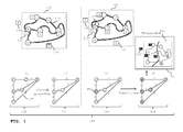
FIG. 1 shows an overview including a geographical area, a computer system and processing in the computer system; -
FIGs. 2A ,2B ,2C illustrate pre-processing by showing graphs, simplified, reduced versions of the graphs, and the elements that have been removed from the graphs; -
FIG. 3 shows a time diagram in combination with a symbolic reference toFIG. 1 to depict the timing of data processing steps; -
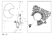
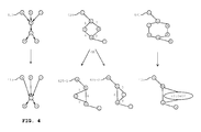
FIG. 4 illustrates examples for pre-processing graphs stored in a data structure; -
FIG. 5 shows exemplary camera frames for an observed event in the real world, a corresponding data structure (with graphs), and corresponding displays; -
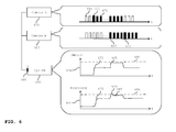
FIG. 6 shows frames from different cameras along a time bar and corresponding resource requirements for sensor-data processing; -
FIG. 7 is an exemplary flow chart according to one embodiment of the computer implemented method of the invention; and -
FIG. 8 is a table to illustrate memory and computation requirements for graphs corresponding to different types of geographical areas. - The figures are non-scaled drawings. The sizes of pictograms, such as geographical areas and system components, are only symbolically and should not be mistaken to be aligned with each other.
-
FIG. 1 shows an overview including ageographical area computer system 120 as well as processing actions in thecomputer system 120.Computer system 120 includes a data structure anddisplay 125. The data structure is illustrated at different time points t1, t2, t3, t4 asdata structure Display 125 showsrepresentation 113 ofgeographical area -
Geographical area 110 can be, for example, a city with roads 116 (inFIG. 1 illustrated by double-lines) and other urban facilities. The roads form a network that may connect locations A, B, C, D, E, F of the geographical area. The figure depicts the locations by circle symbols and the description uses uppercase letters. A location can be, for example, a bus stop, an intersection, a mountain, a police station, or a railway station. Technically, a location can be specified, for example, by longitude and latitude coordinates. -
Geographical area 110 may be populated. People may walk around, drive cars or other vehicles, and ride bicycles. With all these objects in the area, the road traffic can be busy. Therefore, security surveillance might be in place andgeographical area 110 might be monitored by different kinds of sensors. For the following explanation, only a particular object will be described. However, the invention could also be applied for tracing/finding and retrieving multiple objects. Moreover, for illustration purposes cameras will be used as sensors. - In
FIG. 1 , sensors are depicted with a square symbol and the letter S. The placement of the sensors can be withingeographical area 110 or outside. For example,sensor 130 could be located outside the area, for example, in a satellite or on top of a high building next to the geographical area. Within the area,sensor 132 can be positioned at a location of the area. The figure gives an example forlocation B. Sensor 134 might also be positioned somewhere else in the area. - Looking at the observation coverage of sensors, a sensor might monitor a specific location, parts of the area, or the area as a whole. The monitoring direction of a sensor might be directed (e.g., field of view of a camera) or undirected (e.g., vibrations monitored by a seismometer).
Sensor 130 might be located in a satellite to monitorgeographical area 110 as a whole.Sensor 132, however, might only cover the surroundings of location B, whereassensor 134 could monitor a part of the area between locations A and D. - In the following description of
FIG. 1 , different time points t1, t2, t3, t4 are taken into consideration. The different time points are associated with particular conditions of the data structure, which might correlate to the real world. To illustrate the timing, the explanation below follows the time points. - At time point t1,
data structure 121 is a representation ofgeographical area 110.Geographical area 110 is mapped to a graph with nodes a, b, c, d, e, f (lowercase letters) and edges. Nodes a, b, c, d, e, f represent locations A, B, C, D, E, F, respectively. Edges are associated with transition times. The graph can be of any kind as known in the art, such as a directed/undirected graph, a weighted/unweight graph, or combinations of these. Nodes and edges can be associated with multiple attributes each. Examples for attributes are depicted later. - A transition time provides information about the time an object requires to move between two locations. For example, edge 140 of node a and node d has the transition time five (5). The unit of the transition time is not specified for simplicity; it can be, for example, minutes, seconds, or hours. A transition time might have measurement units other than 'time'. For example, a transition time could be associated with the measurement unit 'money' or could be associated with energy consumption. Transition times can also be accumulated for multiple edges which have a common path. The description indicates path by the lowercase letters of the nodes and hyphens. For example, the transition time for movement between location A to location D via location B and C can be accumulated by considering the edges on the path with nodes a-b-c-d to the
overall value 2 + 2 + 3 = 7. - The transition time may be derived from various attributes which influence the overall transition time. This value may consider attributes from nodes and edges on the path e-f-d. Examples of attributes for nodes are:
- specific location, e.g., 'location=28 River Street';
- intersections, e.g., 'intersection=yes';
- barriers, e.g., 'barrier=lowBridge';
- vehicles and pedestrians on the street, e.g., 'pedestriansCrossing=yes'.
- type of street, e.g., 'street=residential';
- speed limit, e.g., 'speedLimit=10km/h';
- traffic direction, e.g., 'directed=oneWay';
- number of traffic lanes, e.g., 'Lanes=6';
- an identification of the nodes that are connected, e.g., 'listOfNodes=e,f,d'.
- The attributes have different implications, for example, the edge attribute 'Lanes=6' indicates six traffic lanes and, therefore, a lot of cars may pass along this road. Monitoring such a six-lane road might require more sensor resources than, for example, a two-lane-road. Also, the attribute 'directed=oneWay' can have the implication that the transition time depends on the traffic direction. For example, the transition time from node a to node d has the
value 5, however, the transition time vice versa from node d to a via the same edge is considered indefinite, since there is no way in this direction. - The information for transition times may be derived from topographical maps or other data sources. Moreover, additional information about sensors may be available and assigned as attributes to the nodes and edges. Examples for information about sensors are:
- Position/ monitoring direction
- Detection capabilities, for example, the detection of weather conditions such as rain, fog, snow, or ice, can affect other attributes that are related to transition times between locations. For example, the weather condition 'rain' might reduce the attribute 'maximum speed' by 20 %, whereas 'snow' could reduce it by 40 %. Technical data of the type of sensor, for example, internal parameters (e.g., a camera sensor has internal parameters such as focal length, principal point, pixel size, horizontal and vertical field of view, movement focus)
- Setup data of the sensor, for example, external parameters (e.g., coordinate positions in space (latitude, longitude, height above the ground))
- calibration data (e.g., transformation parameters to map pixel coordinates on real world coordinates)
- Monitoring range (e.g., the distance to objects that the sensor can detect)
- area covered (e.g., identification of locations)
- At the time
geographical area 110 is mapped todata structure 121, some information might not be available. In this case, a placeholder (e.g., a variable) can be associated to an edge or a node. Examples for such information might be weather conditions (e.g., rain, fog), flooding, persons using the streets (e.g., during festivals, demonstrations, or riots), construction sites, and road blocks. This information can have various consequences which are not known at the timegeographical area 110 is mapped ontodata structure 121, for example, flooding or road blocks might set the transition time to indefinite and, therefore, basically make an edge obsolete. -
Data structure 122 at time point t2 is slightly different compared todata structure 121 at time point t1. In comparison to the graph ofdata structure 121, the graph ofdata structure 122 has a smaller number of edges and nodes. The reduction is achieved by a pre-processing of attributes bycomputer system 120 or any other system. For example, to travel from location E to location D, the transition times might be accumulated to 1 + 1 = 2 without losing information. This is possible when the attributes can be consolidated. An example where attributes might not be able to be consolidated could be the attribute 'directed=oneWay' at the edge of node e to node f (directed edge). This prevents the removal of node f, since the edge of node f to node d is undirected. Therefore, the creation of a new edge from node e to node d is not possible. As a result of the pre-processing, the pre-processed graph requires less storage and memory resources and can be more efficiently processed by a computer running graph algorithms. Further, a computer system requires less time for calculating paths of the graph. - Pre-processing the graph can be done with or without information for the placeholders. For example, a pre-processed graph can be generated every day when information for this particular day is available. The sensor selection during the tracing of an object might then use the daily generated pre-processed graph in
data structure 122. - Pre-processing is implemented by rules which can combine edges and, thus, remove nodes. In the process, new edges are defined. Different attributes are combined in different ways. Now looking at the pre-processing of
data structure 121 to obtaindata structure 122 an example can be:
function(
         edge_1{nodes="e,f", distance=1km, speedLimit=60km/h, directed=twoWay},
         node_f{location=28 River Street, camera=no},
         edge_2{nodes="f,d", distance=1.5km, speedLimit=90km/h, directed=twoWay})
wherein an example rule is (pseudo code):
         if speedLimit edge_1 and edge_2 not equal
         then calculate effectiveMaxSpeed as
            (edge_1(distance*speedLimit)+edge_2(distance*speedLimit))
            divided by
            (edge_1(distance)+ edge_2(distance));
            add effectiveMaxSpeed to the list of attributes of edge_new;
         else speed limit of edge_new is speedLimit is speedlimit of edge_1.
with a result of:
         edge_new{nodes="e,f,d", distance=2.5km, speedLimit=60:90km/h, directed=twoWay,
         effectiveMaxSpeed=78km/h}
As mentioned before, not all edges/nodes are combinable. Therefore, a rule may not be applicable and just give the output that it is unable to combine.
Claims (15)
- A computer implemented method (700) for selecting at least one sensor from a plurality of sensors (130,132,134) for monitoring a geographical area (110,112), wherein a data structure (120,121,122,123) with a pre-processed graph represents the geographical area (110,112), the pre-processed graph having nodes (a,b,c,d,e,f) representing locations (A,B,C,D,E,F) and having edges representing transition times (140) for objects (537) if moving between the locations (A,B,C,D,E,F), and wherein the pre-processed graph is a simplified version of an original graph, the method comprising:receiving an event (135) indicator in relation to a particular location (B);identifying (720) a particular node (145,b) that represents the particular location (B);identifying (730) further nodes (a,c,e) for which accumulated transition times from the particular node (b) have values in a predefined relation to a time interval (Ttrace) from the event (135); andselecting (704) at least one sensor (130') from the plurality of sensors (130,132,134) that is related to the locations represented by the identified nodes (a,b,c,e).
- The method of claim 1, wherein at least one node represents a sensor location.
- The method of anyone of the claims 1 to 2, further comprising associating at least one element of the graph with a placeholder for first information that is related to the geographical area, wherein the first information adjusts the transition time between two locations.
- The method of claim 3, further comprising receiving the first information from the sensors.
- The method of claim 3, further comprising receiving the first information from external sources.
- The method of anyone of the claims 1 to 5, wherein a particular object in relation to the particular location (B) is being associated with second information; the method further comprising adjusting the processing of sensor-data recorded by the selected sensors according to that second information.
- The method of anyone of the claims 1 to 6, further comprising to repeat the step of identifying further nodes using the same predefined relation to a further time interval from the event that is longer than the previously used time interval.
- The method of anyone of the claims 1 to 7, upon receiving a further event indicator (539) in relation to the particular object (537), wherein the particular object (537) is related to a new particular location in the geographical area, the method further comprising:deselecting all selected sensors; and repeating the following steps:identifying a new particular node (543/e) that represents the new particular location;identifying new further nodes for which the accumulated transition times from the new particular node have values in a predefined relation to a new time interval from the further event; andselecting at least one new sensor (536') from the plurality of sensors that is related to the locations represented by the new identified nodes.
- The method of anyone of the claims 1 to 8, further comprising: displaying a visualization (113) of the geographical area (110,112), wherein the geographical area is divided into an exclusion and inclusion area, and wherein the inclusion area is defined based on the identified nodes.
- The method of anyone of the claims 1 to 9, further comprising: displaying a visualization of probability of the particular object to move to the locations, and wherein the probability is dependent on values assigned to the particular object.
- The method of anyone of the claims 1 to 10, wherein a part of the graph is specialized for an object type.
- The method of anyone of the claims 1 to 11, wherein data to identify the particular location is received from a user interface.
- A computer program product that when loaded into a memory of a computing system and executed by at least one processor of the computing device executes the steps of the computer implemented method according to anyone of the claims 1 to 12.
- A computer system for selecting at least one sensor from a plurality of sensors (130,132,134), wherein the at least one sensor is adapted to record sensor-data that is related to a geographical area (110,112), wherein the sensor-data comprises information about objects (537) movable between locations (A,B,C,D,E,F) of that geographical area (110,112), wherein a data structure (120,121,122,123) with a pre-processed graph represents the geographical area (110,112), the pre-processed graph having elements comprising nodes and edges, wherein nodes (a,b,c,d,e,f) represent the locations (A,B,C,D,E,F) of the geographical area (110,112), wherein edges represent transition times (140) for the objects (537) if moving between the locations (A,B,C,D,E,F), and wherein the pre-processed graph has a simplified number of nodes (a,b,c,d,e,f) according to rules applied to the elements, comprising:a receiver component adapted to receive (710) an event (135) indicator in relation to a particular location (B);a first identifier component configured to identify (720) a particular node (145,b) that represents that particular location (B);a second identifier component configured to identify (730) further nodes (a,c,e) for which accumulated transition times from the particular node (b) have values in a predefined relation to a time interval (Ttrace) from the event (135); anda selector component configured to select (740) at least one sensor (130') from the plurality of sensors (130,132,134) that is related to the locations represented by the identified nodes (a,b,c,e).
- The computer system of claim 14, further comprising: a display component adapted to display (756) a visualization (113) of the geographical area (110,112), wherein the geographical area is divided into an exclusion and inclusion area, and wherein the inclusion area is defined based on the identified nodes.
Priority Applications (3)
| Application Number | Priority Date | Filing Date | Title |
|---|---|---|---|
| EP12190467.6A EP2725552A1 (en) | 2012-10-29 | 2012-10-29 | System and method for selecting sensors in surveillance applications |
| US14/438,887 US20150281653A1 (en) | 2012-10-29 | 2013-10-29 | System and method for selecting sensors in surveillance applications |
| PCT/EP2013/072590 WO2014067935A1 (en) | 2012-10-29 | 2013-10-29 | System and method for selecting sensors in surveillance applications |
Applications Claiming Priority (1)
| Application Number | Priority Date | Filing Date | Title |
|---|---|---|---|
| EP12190467.6A EP2725552A1 (en) | 2012-10-29 | 2012-10-29 | System and method for selecting sensors in surveillance applications |
Publications (1)
| Publication Number | Publication Date |
|---|---|
| EP2725552A1 true EP2725552A1 (en) | 2014-04-30 |
Family
ID=47357905
Family Applications (1)
| Application Number | Title | Priority Date | Filing Date |
|---|---|---|---|
| EP12190467.6A Withdrawn EP2725552A1 (en) | 2012-10-29 | 2012-10-29 | System and method for selecting sensors in surveillance applications |
Country Status (3)
| Country | Link |
|---|---|
| US (1) | US20150281653A1 (en) |
| EP (1) | EP2725552A1 (en) |
| WO (1) | WO2014067935A1 (en) |
Cited By (3)
| Publication number | Priority date | Publication date | Assignee | Title |
|---|---|---|---|---|
| US10362274B2 (en) | 2014-10-30 | 2019-07-23 | Nec Corporation | Monitoring system, monitoring method and storage medium |
| CN114365505A (en) * | 2019-11-07 | 2022-04-15 | 阿里巴巴集团控股有限公司 | Data-driven object graph for data center monitoring |
| CN116708035A (en) * | 2023-08-07 | 2023-09-05 | 钛合联(深圳)科技有限公司 | Network data security encryption method and system |
Families Citing this family (7)
| Publication number | Priority date | Publication date | Assignee | Title |
|---|---|---|---|---|
| US20150312535A1 (en) * | 2014-04-23 | 2015-10-29 | International Business Machines Corporation | Self-rousing surveillance system, method and computer program product |
| US9928594B2 (en) | 2014-07-11 | 2018-03-27 | Agt International Gmbh | Automatic spatial calibration of camera network |
| KR20160014242A (en) * | 2014-07-29 | 2016-02-11 | 삼성전자주식회사 | Method and device for mapping location of sensor and event operation with monitoring device |
| US9866507B2 (en) | 2015-04-27 | 2018-01-09 | Agt International Gmbh | Method of monitoring well-being of semi-independent persons and system thereof |
| US10521913B2 (en) * | 2018-03-29 | 2019-12-31 | Aurora Innovation, Inc. | Relative atlas for autonomous vehicle and generation thereof |
| US10686670B2 (en) | 2018-08-21 | 2020-06-16 | International Business Machines Corporation | Optimizing placement of internet-of-things (IoT) devices to provide full coverage and minimize coverage overlap |
| US11062162B2 (en) * | 2019-08-27 | 2021-07-13 | Motorola Solutions, Inc. | Breaking pursuit and strategy change |
Citations (4)
| Publication number | Priority date | Publication date | Assignee | Title |
|---|---|---|---|---|
| WO2007094802A2 (en) * | 2005-03-25 | 2007-08-23 | Intellivid Corporation | Intelligent camera selection and object tracking |
| US20080130951A1 (en) * | 2006-11-30 | 2008-06-05 | Wren Christopher R | System and Method for Modeling Movement of Objects Using Probabilistic Graphs Obtained From Surveillance Data |
| US20110064269A1 (en) * | 2009-09-14 | 2011-03-17 | Manipal Institute Of Technology | Object position tracking system and method |
| GB2482127A (en) * | 2010-07-19 | 2012-01-25 | Ipsotek Ltd | Scene object tracking and camera network mapping based on image track start and end points |
-
2012
- 2012-10-29 EP EP12190467.6A patent/EP2725552A1/en not_active Withdrawn
-
2013
- 2013-10-29 US US14/438,887 patent/US20150281653A1/en not_active Abandoned
- 2013-10-29 WO PCT/EP2013/072590 patent/WO2014067935A1/en active Application Filing
Patent Citations (4)
| Publication number | Priority date | Publication date | Assignee | Title |
|---|---|---|---|---|
| WO2007094802A2 (en) * | 2005-03-25 | 2007-08-23 | Intellivid Corporation | Intelligent camera selection and object tracking |
| US20080130951A1 (en) * | 2006-11-30 | 2008-06-05 | Wren Christopher R | System and Method for Modeling Movement of Objects Using Probabilistic Graphs Obtained From Surveillance Data |
| US20110064269A1 (en) * | 2009-09-14 | 2011-03-17 | Manipal Institute Of Technology | Object position tracking system and method |
| GB2482127A (en) * | 2010-07-19 | 2012-01-25 | Ipsotek Ltd | Scene object tracking and camera network mapping based on image track start and end points |
Cited By (6)
| Publication number | Priority date | Publication date | Assignee | Title |
|---|---|---|---|---|
| US10362274B2 (en) | 2014-10-30 | 2019-07-23 | Nec Corporation | Monitoring system, monitoring method and storage medium |
| US10893240B2 (en) | 2014-10-30 | 2021-01-12 | Nec Corporation | Camera listing based on comparison of imaging range coverage information to event-related data generated based on captured image |
| US11800063B2 (en) | 2014-10-30 | 2023-10-24 | Nec Corporation | Camera listing based on comparison of imaging range coverage information to event-related data generated based on captured image |
| CN114365505A (en) * | 2019-11-07 | 2022-04-15 | 阿里巴巴集团控股有限公司 | Data-driven object graph for data center monitoring |
| CN116708035A (en) * | 2023-08-07 | 2023-09-05 | 钛合联(深圳)科技有限公司 | Network data security encryption method and system |
| CN116708035B (en) * | 2023-08-07 | 2023-10-03 | 钛合联(深圳)科技有限公司 | Network data security encryption method and system |
Also Published As
| Publication number | Publication date |
|---|---|
| WO2014067935A1 (en) | 2014-05-08 |
| US20150281653A1 (en) | 2015-10-01 |
Similar Documents
| Publication | Publication Date | Title |
|---|---|---|
| EP2725552A1 (en) | System and method for selecting sensors in surveillance applications | |
| EP3673407B1 (en) | Automatic occlusion detection in road network data | |
| EP3357049B1 (en) | Transmission of targeted roadway alerts | |
| Iqbal et al. | Intelligent transportation system (ITS) for smart-cities using Mamdani fuzzy inference system | |
| US9672735B2 (en) | Traffic classification based on spatial neighbor model | |
| CN105761500A (en) | Traffic accident handling method and traffic accident handling device | |
| Salvo et al. | Traffic data acquirement by unmanned aerial vehicle | |
| JP2014527617A (en) | Route provision through information collection and extraction | |
| WO2021082464A1 (en) | Method and device for predicting destination of vehicle | |
| Saremi et al. | Combining map-based inference and crowd-sensing for detecting traffic regulators | |
| US10319229B1 (en) | Data mining for alerts regarding road conditions | |
| Costanzo | An arduino based system provided with GPS/GPRS shield for real time monitoring of traffic flows | |
| Kotha et al. | Potsense: Pothole detection on indian roads using smartphone sensors | |
| Tarapiah et al. | Offline public transportation management system based on GPS/WiFi and open street maps | |
| CN110646002B (en) | Method and apparatus for processing information | |
| CN114662583A (en) | Emergency event prevention and control scheduling method and device, electronic equipment and storage medium | |
| CN114004566A (en) | Danger warning method, device and storage medium | |
| Nair et al. | Hybrid segmentation approach to identify crash susceptible locations in large road networks | |
| Marques et al. | An evaluation of machine learning methods for speed-bump detection on a GoPro dataset | |
| Plaudis et al. | An Algorithmic Approach to Quantifying GPS Trajectory Error | |
| CN114771576A (en) | Behavior data processing method, control method of automatic driving vehicle and automatic driving vehicle | |
| CN115060249A (en) | Electronic map construction method, device, equipment and medium | |
| CN113660462A (en) | Surrounding ring type mobile vehicle video tracking method based on fusion multi-source data analysis | |
| Yang et al. | Three-dimensional structure determination of grade-separated road intersections from crowdsourced trajectories | |
| CN115982306B (en) | Method and device for identifying retrograde behavior of target object |
Legal Events
| Date | Code | Title | Description |
|---|---|---|---|
| PUAI | Public reference made under article 153(3) epc to a published international application that has entered the european phase |
Free format text: ORIGINAL CODE: 0009012 |
|
| 17P | Request for examination filed |
Effective date: 20121029 |
|
| AK | Designated contracting states |
Kind code of ref document: A1 Designated state(s): AL AT BE BG CH CY CZ DE DK EE ES FI FR GB GR HR HU IE IS IT LI LT LU LV MC MK MT NL NO PL PT RO RS SE SI SK SM TR |
|
| AX | Request for extension of the european patent |
Extension state: BA ME |
|
| REG | Reference to a national code |
Ref country code: HK Ref legal event code: DE Ref document number: 1191433 Country of ref document: HK |
|
| RAP1 | Party data changed (applicant data changed or rights of an application transferred) |
Owner name: ATS GROUP (IP HOLDINGS) LIMITED |
|
| 17P | Request for examination filed |
Effective date: 20141030 |
|
| RBV | Designated contracting states (corrected) |
Designated state(s): AL AT BE BG CH CY CZ DE DK EE ES FI FR GB GR HR HU IE IS IT LI LT LU LV MC MK MT NL NO PL PT RO RS SE SI SK SM TR |
|
| RAP1 | Party data changed (applicant data changed or rights of an application transferred) |
Owner name: AGT INTERNATIONAL GMBH |
|
| 17Q | First examination report despatched |
Effective date: 20170406 |
|
| STAA | Information on the status of an ep patent application or granted ep patent |
Free format text: STATUS: THE APPLICATION IS DEEMED TO BE WITHDRAWN |
|
| 18D | Application deemed to be withdrawn |
Effective date: 20171017 |
|
| REG | Reference to a national code |
Ref country code: HK Ref legal event code: WD Ref document number: 1191433 Country of ref document: HK |