EP2723123A1 - Autonomous determination of optimal values for handover parameters - Google Patents
Autonomous determination of optimal values for handover parameters Download PDFInfo
- Publication number
- EP2723123A1 EP2723123A1 EP12306292.9A EP12306292A EP2723123A1 EP 2723123 A1 EP2723123 A1 EP 2723123A1 EP 12306292 A EP12306292 A EP 12306292A EP 2723123 A1 EP2723123 A1 EP 2723123A1
- Authority
- EP
- European Patent Office
- Prior art keywords
- handover
- values
- ttt
- cell
- mobile stations
- Prior art date
- Legal status (The legal status is an assumption and is not a legal conclusion. Google has not performed a legal analysis and makes no representation as to the accuracy of the status listed.)
- Withdrawn
Links
- 238000005259 measurement Methods 0.000 claims abstract description 53
- 238000000034 method Methods 0.000 claims abstract description 45
- 238000012512 characterization method Methods 0.000 claims abstract description 25
- 238000001514 detection method Methods 0.000 claims abstract description 24
- 238000005457 optimization Methods 0.000 claims abstract description 23
- 238000002922 simulated annealing Methods 0.000 claims description 13
- 230000001965 increasing effect Effects 0.000 claims description 6
- 238000000528 statistical test Methods 0.000 claims description 3
- 230000008859 change Effects 0.000 description 15
- 230000006870 function Effects 0.000 description 15
- 238000004891 communication Methods 0.000 description 7
- 230000008569 process Effects 0.000 description 6
- 238000012360 testing method Methods 0.000 description 6
- 230000001960 triggered effect Effects 0.000 description 6
- 230000008878 coupling Effects 0.000 description 4
- 238000010168 coupling process Methods 0.000 description 4
- 238000005859 coupling reaction Methods 0.000 description 4
- 238000005516 engineering process Methods 0.000 description 4
- 238000001914 filtration Methods 0.000 description 4
- 238000001816 cooling Methods 0.000 description 3
- 230000003247 decreasing effect Effects 0.000 description 3
- 238000007726 management method Methods 0.000 description 3
- 238000012545 processing Methods 0.000 description 3
- 238000000137 annealing Methods 0.000 description 2
- 238000013459 approach Methods 0.000 description 2
- 230000008901 benefit Effects 0.000 description 2
- 230000005540 biological transmission Effects 0.000 description 2
- 230000007774 longterm Effects 0.000 description 2
- 238000007476 Maximum Likelihood Methods 0.000 description 1
- 230000003044 adaptive effect Effects 0.000 description 1
- 230000003139 buffering effect Effects 0.000 description 1
- 230000015556 catabolic process Effects 0.000 description 1
- 230000008094 contradictory effect Effects 0.000 description 1
- 230000001955 cumulated effect Effects 0.000 description 1
- 230000001186 cumulative effect Effects 0.000 description 1
- 230000007423 decrease Effects 0.000 description 1
- 238000006731 degradation reaction Methods 0.000 description 1
- 230000001419 dependent effect Effects 0.000 description 1
- 238000013461 design Methods 0.000 description 1
- 238000011161 development Methods 0.000 description 1
- 230000018109 developmental process Effects 0.000 description 1
- 238000003745 diagnosis Methods 0.000 description 1
- 238000009826 distribution Methods 0.000 description 1
- 238000005315 distribution function Methods 0.000 description 1
- 230000002708 enhancing effect Effects 0.000 description 1
- 238000009472 formulation Methods 0.000 description 1
- 238000007710 freezing Methods 0.000 description 1
- 230000008014 freezing Effects 0.000 description 1
- 238000010438 heat treatment Methods 0.000 description 1
- 230000000977 initiatory effect Effects 0.000 description 1
- 238000007689 inspection Methods 0.000 description 1
- 239000000463 material Substances 0.000 description 1
- 230000007246 mechanism Effects 0.000 description 1
- 239000002184 metal Substances 0.000 description 1
- 238000005272 metallurgy Methods 0.000 description 1
- 239000000203 mixture Substances 0.000 description 1
- 238000012544 monitoring process Methods 0.000 description 1
- 230000006855 networking Effects 0.000 description 1
- 230000010355 oscillation Effects 0.000 description 1
- 230000000737 periodic effect Effects 0.000 description 1
- 230000002688 persistence Effects 0.000 description 1
- 230000002085 persistent effect Effects 0.000 description 1
- 230000003094 perturbing effect Effects 0.000 description 1
- 238000011160 research Methods 0.000 description 1
- 230000011218 segmentation Effects 0.000 description 1
- 238000007493 shaping process Methods 0.000 description 1
- 230000011664 signaling Effects 0.000 description 1
- 238000003860 storage Methods 0.000 description 1
Images


Classifications
-
- H—ELECTRICITY
- H04—ELECTRIC COMMUNICATION TECHNIQUE
- H04W—WIRELESS COMMUNICATION NETWORKS
- H04W36/00—Hand-off or reselection arrangements
- H04W36/0005—Control or signalling for completing the hand-off
- H04W36/0009—Control or signalling for completing the hand-off for a plurality of users or terminals, e.g. group communication or moving wireless networks
-
- H—ELECTRICITY
- H04—ELECTRIC COMMUNICATION TECHNIQUE
- H04W—WIRELESS COMMUNICATION NETWORKS
- H04W36/00—Hand-off or reselection arrangements
- H04W36/0005—Control or signalling for completing the hand-off
- H04W36/0007—Control or signalling for completing the hand-off for multicast or broadcast services, e.g. MBMS
-
- H—ELECTRICITY
- H04—ELECTRIC COMMUNICATION TECHNIQUE
- H04W—WIRELESS COMMUNICATION NETWORKS
- H04W36/00—Hand-off or reselection arrangements
- H04W36/0005—Control or signalling for completing the hand-off
- H04W36/0083—Determination of parameters used for hand-off, e.g. generation or modification of neighbour cell lists
- H04W36/00835—Determination of neighbour cell lists
-
- H—ELECTRICITY
- H04—ELECTRIC COMMUNICATION TECHNIQUE
- H04W—WIRELESS COMMUNICATION NETWORKS
- H04W36/00—Hand-off or reselection arrangements
- H04W36/0005—Control or signalling for completing the hand-off
- H04W36/0083—Determination of parameters used for hand-off, e.g. generation or modification of neighbour cell lists
- H04W36/00837—Determination of triggering parameters for hand-off
-
- H—ELECTRICITY
- H04—ELECTRIC COMMUNICATION TECHNIQUE
- H04W—WIRELESS COMMUNICATION NETWORKS
- H04W24/00—Supervisory, monitoring or testing arrangements
- H04W24/02—Arrangements for optimising operational condition
-
- H—ELECTRICITY
- H04—ELECTRIC COMMUNICATION TECHNIQUE
- H04W—WIRELESS COMMUNICATION NETWORKS
- H04W36/00—Hand-off or reselection arrangements
- H04W36/0005—Control or signalling for completing the hand-off
- H04W36/0083—Determination of parameters used for hand-off, e.g. generation or modification of neighbour cell lists
- H04W36/0085—Hand-off measurements
- H04W36/0094—Definition of hand-off measurement parameters
Definitions
- the present invention relates to mobility within a mobile or wireless network, and more specifically to the configuration of handover parameters used for detecting that a given neighboring cell fulfills a given handover condition within a given serving cell.
- RRM Radio Resource Management
- the handover procedure is performed upon triggering conditions which have to be properly configured and optimized so that target Quality of service (Qos) and Quality of Experience (QoE) objectives are achieved.
- Qos Quality of service
- QoE Quality of Experience
- MRO Mobility Robustness Optimization
- handover is performed as following.
- the user performs periodic measurements, typically filtered Reference Signal Received Powers (RSRP) on the serving (Ms) and neighbor cells (Mn).
- RSRP Reference Signal Received Powers
- Ms serving
- Mn neighbor cells
- RSRP Reference Signal Received Powers
- the UE reports its measurements to the serving cell, which eventually decides to trigger or not a handover based on the user's recommendations.
- A3 event reporting by the UE is triggered if at least one neighbor cell becomes better than the serving cell by a configurable offset value.
- Handover reporting measurement by the UE is triggered if the condition is met for a minimal configurable duration or Time-To-Trigger (TTT).
- TTT Time-To-Trigger
- the hysteresis parameter is iteratively adjusted (increased/decreased) so as to minimize handover failure rate, accounting for neighbor cells load, the user speed or the traffic type.
- a method for adjusting handover parameters used for handover detection within a given serving cell comprises, for respective ones of a plurality of mobile stations served by the serving cell, gathering measurement samples of the serving cell and of a respective neighboring cell carried out by a respective mobile station at successive time instances, and determining delta values indicative of the time-indexed difference between respective ones of the measurement samples of the serving cell and corresponding ones of the measurement samples of the neighboring cell.
- the method further comprises determining near-optimal values for the handover parameters by statistical characterization of the ensembles of delta values for the plurality of mobile stations.
- a configuration agent for adjusting handover parameters used for handover detection within a given serving cell is adapted, for respective ones of a plurality of mobile stations served by the serving cell, to gather measurement samples of the serving cell and of a respective neighboring cell carried out by a respective mobile station at successive time instances, and to determine delta values indicative of the time-indexed difference between respective ones of the measurement samples of the serving cell and corresponding ones of the measurement samples of the neighboring cell.
- the configuration agent is further adapted to determine near-optimal values for the handover parameters by statistical characterization of the ensembles of delta values for the plurality of mobile stations.
- the configuration agent may form part of either a radio access node, such as an evolved NodeB (eNB), a radio access controller, such as a Base Station Controller (BSC) or a Radio Network Controller (RNC), or a network manager.
- a radio access node such as an evolved NodeB (eNB)
- eNB evolved NodeB
- BSC Base Station Controller
- RNC Radio Network Controller
- the near-optimal values are input to an iterative closed-loop optimization algorithm in order to determine optimal values for the handover parameters.
- the iterative closed-loop optimization algorithm is based on a Simulated Annealing (SA) algorithm.
- SA Simulated Annealing
- the measurement samples are indicative of the respective strengths of pilot signals received by the respective mobile stations from the respective serving and neighboring cells.
- the measurement samples are indicative of the respective qualities of pilot signals received by the respective mobile stations from the respective serving and neighboring cells.
- the plurality of mobile stations belongs to a particular speed class, and the near-optimal values for the handover parameters are determined on per speed class basis.
- the statistical characterization of the ensembles of delta values for the plurality of mobile stations involves the characterization of variances of the delta values for respective ones of the plurality of mobile stations over varying time windows.
- This embodiment is particularly helpful for determining the near-optimal values for TTT and/or offset handover parameters.
- the method further comprises, for respective ones of the plurality of mobile stations, and from a given time index onwards, estimating variance values over a time-window of K successive delta values for respective increasing K values, and determining a minimum time-window length beyond which the so-determined variance values lies within a given small interval.
- the method further comprises determining a Time-To-Trigger TTT value, during which measurement samples of the serving cell and a given target cell shall fulfill the handover condition before triggering a handover, by statistical characterization of the so-determined minimum time-window lengths for the plurality of mobile terminals.
- the configuration agent is further adapted, for respective ones of the plurality of mobile stations, and from a given time index onwards, to estimate variance values over a time-window of K successive delta values for respective increasing K values, and to determine a minimum time-window length beyond which the so-determined variance values lies within a given small interval.
- the configuration agent is further adapted to determine a Time-To-Trigger TTT value, during which measurement samples of the serving cell and a given target cell shall fulfill a given handover condition, by statistical characterization of the so-determined minimum time-window lengths for the plurality of mobile terminals.
- the so-determined TTT value is such that a given proportion of the so-determined minimum time-window lengths for the plurality of mobile stations are lower than or equal to the TTT value.
- the method further comprises determining a nominal variance value by statistical characterization of the so-estimated variance values, and inputting the so-determined nominal variance value, along with a first upper bound for a handover detection time and a second upper bound for a false handover detection rate, to a Page Hinkley statistical test so as to determine an offset value whereby the target cell shall be measured offset-better than the serving cell for the handover condition to be fulfilled.
- the configuration agent is further adapted to determine a nominal variance value by statistical characterization of the so-estimated variance values, and inputting the so-determined nominal variance value, along with a first upper bound for a handover detection time and a second upper bound for a false handover detection rate, to a Page Hinkley statistical test so as to determine an offset value whereby the target cell shall be measured offset-better than the serving cell for the handover condition to be fulfilled.
- the nominal variance value is determined such that a further given proportion of the variance values estimated for the plurality of mobile stations over time-windows of lengths equal to the TTT value are lower than or equal to the nominal variance value.
- the determination of the offset value is instantiated on a per neighboring cell basis, and the first upper bound is adjusted based on an inter-site distance between the serving cell and a given neighboring cell and based on the particular speed class.
- the proposed solution relies on theoretical framework to jointly estimate the handover parameters based on handover counters specified by the MRO feature in 3GPP specification. This has the advantage to enable easy and direct implementation in real networks.
- the proposed scheme relies on a two-stage procedure where the first stage is a learning (or sensing) phase to find out near-optimal values for the handover parameters by statistical characterization of the measurement samples gathered from the mobile stations, and the second stage is an optimization stage to fine-tune the handover parameter values by means of an iterative closed-loop algorithm, starting from the near optimal values output from the first stage.
- the first stage is a learning (or sensing) phase to find out near-optimal values for the handover parameters by statistical characterization of the measurement samples gathered from the mobile stations
- the second stage is an optimization stage to fine-tune the handover parameter values by means of an iterative closed-loop algorithm, starting from the near optimal values output from the first stage.
- the first stage is a learning (or sensing) phase to find out near-optimal values for the handover parameters by statistical characterization of the measurement samples gathered from the mobile stations
- the second stage is an optimization stage to fine-tune the handover parameter values by means of an iterative closed-l
- E-RAN Evolved Radio Access Network
- EPC Evolved Packet Core
- the eNBs 10 are coupled to the MME 20 through an S1-MME interface, and to the S-GW 30 through an S1-U interface.
- the S-GW 30 is further coupled to the P-GW 40 through an S5 interface.
- the P-GW 40 is further coupled to a PDN 50 through an SGi interface.
- the neighboring eNBs 10 establish neighbor relationships through an X2 interface.
- the eNBs 10 operate macro, micro or pico cells with a radio coverage area ranging from a few kilometers up to a few tens meters.
- the eNBs 10 are configured to set up and operate radio communication channels (i.e., a set of downlink and uplink traffic radio resources) with the UEs 60 through a Uu radio interface.
- each of the eNBs 10 hosts the following functions:
- the MME 20 hosts the following functions:
- the S-GW 30 hosts the following functions:
- the P-GW 40 hosts the following functions:
- FIG. 2 further details about an eNB 100 as per the present invention, and configured to operate one or more serving cells.
- the eNB 100 comprises the following functional blocks:
- the network termination unit 130 is coupled to the digital base-band unit 111, the digital base-band unit 111 is coupled to the analog band-pass unit 112, the analog band-pass unit 112 is coupled to the coupling unit 120, and the coupling unit 120 is coupled to an external or internal antenna 180.
- the radio resource controller 140 is coupled to the transceivers 110.
- the handover configuration agent 150 is coupled to the radio resource controller 140.
- the UE speed characterization unit 160 and the cell characterization unit 170 are coupled to the handover configuration agent 150.
- the transceivers 110 are configured to establish and operate radio communication channels with UEs under control of the radio resource controller 140.
- the digital base-band unit 111 is for digitally processing the received and transmit data symbols.
- the digital base-band unit 111 implements the necessary protocol suites for issuing, terminating or relaying data and control packets.
- the analog band-pass unit 112 is for modulating, amplifying and shaping the transmit signal that ultimately feds the antenna 180, and for filtering, amplifying with as little noise as possible and demodulating the received signal from the antenna 180.
- the analog band-pass 112 unit can be merged with the digital base-band unit, or can be moved closer to the antenna in a so-called Remote Radio Head-end (RRH) configuration.
- RRH Remote Radio Head-end
- the coupling unit 120 is for combining and passing the transmit signals from the transceivers 110 towards the antenna 180, and for dispatching the receive signal from the antenna 180 towards the transceivers 110.
- the network termination unit 130 accommodates the appropriate Medium Access Control (MAC) and Physical transport (PHY) layers for communication through a PDN, as well as some frame dispatching logic for routing the incoming/outgoing frames towards the appropriate Input/output (I/O) ports.
- MAC Medium Access Control
- PHY Physical transport
- the radio resource controller 140 is for assigning and managing downlink and uplink radio resources used by the transceivers 110 and the respective UEs for radio communication over the air interface, that is to say a set of time and/or frequency resources assigned to a serving cell operated by the eNB 100 for transport of user or control traffic within that serving cell. More noticeably, the radio resource controller 140 makes decisions for outgoing handovers from the current serving cell towards a more suitable neighboring cell based on the UE measurement reports.
- the radio resource controller 140 is for further configuring an ad-hoc measurement policy within the one or more serving cells operated by the eNB 100 (see "Meas_Policy(CS)" in fig. 2 ).
- the UEs are configured with a trigger criteria for reporting the cell measurements to the eNB 100.
- the UEs are configured to periodically report the receive power or quality of the serving cell and of one or more best neighboring cells at a given reporting interval.
- the UEs are then configured to trigger measurement reporting only upon fulfillment of a particular handover condition, as typical in LTE networks.
- the cell measurement data gathered during the sensing phase are held in a local data repository for further retrieval by the handover configuration agent 150 (see "M(i,CS,k); M(i,CN,k)" in fig. 2 ), along with further measurement context data such as the UE identity, the UE speed category, the UE location, the time-of-the-day the measurements took place, the user device manufacturer, etc.
- the UEs are also configured with one or more handover conditions for detecting that a given neighboring cell is a more suitable candidate cell for radio communication.
- the UEs can be configured with an A3 handover condition (neighboring becomes offset better than serving) that comprises an hysteresis value HYS, a TTT value, a generic offset value OFF, and possibly cell-specific offset values OCN to manage specificities towards particular neighboring cells.
- the values of these parameters are directly obtained from the handover configuration agent 150.
- a so-configured UE reports an A3 measurement event whenever the received power of a reference signal from a neighboring cell is measured as being better than the receive power of a reference signal from the serving cell by the offset amount OFF - possibly increased or decreased by the cell individual offset OCN - and for TTT seconds.
- the hysteresis HYS prevents excessive toggling between the A3 entering and leaving condition.
- the Entering and Leaving A3 conditions are defined by the following inequalities: Mn + OCN - HYS > Ms + 0 ⁇ FF 1 Entering Condition , Mn + OCN - HYS > Ms + OFF 2 Leaving Condition , Wherein Mn (respectively Ms) denotes the Layer 3 (L3) filtered Reference Signal Receive Power (RSRP) from the neighbor (respectively serving) cell.
- Mn denotes the Layer 3 (L3) filtered Reference Signal Receive Power (RSRP) from the neighbor (respectively serving) cell.
- the handover configuration agent 150 is for processing the UE measurement reports so as to determine optimal values for handover parameters used for handover detection within the one or more serving cells operated by the eNB 100.
- the so-determined handover parameter values are returned to the radio resource controller 140 for proper configuration of the handover conditions (see "TTT(CS); OFF(CS); OCN(CS,CN)" in fig. 2 ).
- the UE speed characterization unit 160 is configured to characterize a particular UE as belonging to a particular speed class, e.g. low/medium/high-speed class (LS/MS/HS) by comparing the UE speed to respective speed thresholds.
- a particular speed class e.g. low/medium/high-speed class (LS/MS/HS)
- the UE speed characterization unit 160 may determine the UE speed category according to first speed information supplied by the UE (e.g., as estimated from GPS positioning data), and/or according to second speed information determined by the eNB 100 (e.g., the Doppler frequency shift is indicative of the radial UE speed with respect to the eNB 100), and/or according to third speed information relayed by a source eNB during an incoming handover procedure (e.g., as derived from the time spent in previous visited cells, or as explicitly encoded by the source eNB).
- first speed information supplied by the UE e.g., as estimated from GPS positioning data
- second speed information determined by the eNB 100 e.g., the Doppler frequency shift is indicative of the radial UE speed with respect to the eNB 100
- third speed information relayed by a source eNB during an incoming handover procedure e.g., as derived from the time spent in previous visited cells, or as explicitly encoded by the source eNB
- the neighboring cell characterization unit 170 is for determining Inter Site Distance (ISD) values between the one or more serving cells operated by the eNB 100 and their respective neighboring cells.
- the ISD values are either derived by characterization of the radio communication environment (possibly involving the UEs), or are field engineering data obtained from a network manager or from a network planning tool.
- the respective ISD values are passed to the handover configuration agent 150 as possible inputs to the optimization algorithm (see "ISD(CS,CN)"in fig. 2 ).
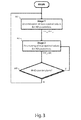
- Fig. 3 represents an overall description of the algorithm that is used within the handover configuration agent 150 for determining optimal values for the handover parameters, namely the handover parameters TTT and OFF.
- the output of the first stage are the near-optimal values TTT NO and OFF NO for the handover parameters, which are the input of the optimisation phase in stage 2.
- the second stage aims at fine-tuning the near-optimal 1 values TTT NO and OFF NO to yield optimal values TTTo and OFFo for the handover parameters (see step 302 in fig. 3 ).
- a condition can be added at this level to provoke a return to stage 1 when needed, e.g. when the performances in term of MRO counters are below a predefined threshold (see step 303 in fig. 3 ).
- the processing of the UE measurements can be made depending on the speed class of the UE (e.g., Small, Medium or High Speed classes) and/or the ISD, that is to say the distance separating the antenna sites of the serving and neighboring cells.
- the speed class of the UE e.g., Small, Medium or High Speed classes
- the ISD that is to say the distance separating the antenna sites of the serving and neighboring cells.
- OFF shall account for the variance of the measurements. For example, small OFF values with strong fluctuations of measurements is likely to lead to false handover alarms.
- TTT is the duration of persistence of the handover condition.
- the condition has to remain verified even if measurements fluctuate. So, TTT is directly linked to how the measurements are spread around their mean values: the variance.
- OFF is computed from the variance of measurements that are estimated over the TTT window size.
- the latter corresponds to the minimum duration over which the variance is stabilized to a steady value.
- M(i,CS,k) and M(i,CN,k) denote the L3-filtered RSRP measurements carried out by a given UE UEi for the serving cell CS and a neighbor cell CN (out of all the neighboring cells of the serving cell CS) at successive time instances k.
- Var ⁇ ⁇ be the variance of the difference ⁇ (i,CN,k) estimated over a time window comprising K measurement samples from a reference time index k0 onwards, wherein K denotes a positive integer value taken from the range [K min ;K max ].
- TTT(i,CN) be the minimum K value beyond which the variance Var ⁇ ⁇ lies within a given small interval around its asymptotic value. This is illustrated in fig. 4A : TTT(i,CN) is the minimum time window beyond which the variance Var ⁇ ⁇ gets substantially constant.
- TTTi computation is re-iterated for further neighboring cells as measured by the UE UEi, as well as for further attached UEs at various geographical positions within the serving cell CS, thereby yielding a statistical ensemble ⁇ TTT(-i,CN) ⁇ i,CN .
- TTT NO CDF 90 % ⁇ TTT i ⁇ CN i , CN
- handover decision should be ideally triggered as soon as the signal received from the neighbor cell exceeds the signal from the serving cell by a given handover margin.
- Change detection comes to detecting a change in mean values of the difference between M(i,CS,k) and M(i,CN,k).
- R is the delay separating the instant the neighboring cell is detected offset-better than the serving cell and the instant the handover decision is made. Minimizing R comes to minimizing the risk of Too Late HO; and maximizing F comes to minimizing the risk for Too Early HO and HO to Wrong Cells.
- OFF NO ⁇ ⁇ 2 ⁇ Log F HO / R HO
- F HO denotes the target maximum duration that can be tolerated between two HO failures of type HO Too early or HO To wrong cells
- R HO denotes the upper bound on the detection duration (distance from the frontier between 2 cells and the actual Handover Decision) that shall occur before the users cross the cell boundary (otherwise handover fails because triggered too lately).
- R HO is either set by the operator in such a way that users have completed their handover before crossing the cell boundary, or is estimated as the probable duration from the frontier between the cells and the cell boundary.
- ⁇ 2 is set to a nominal variance value derived from the statistics of the previously computed var ⁇ A with K being set to the generic TTT value. For instance, ⁇ 2 is set as the CDF at 90% of the statistical ensembles ⁇ Var TTT ⁇ (i, CN) ⁇ i,CN .
- TTT is derived from the variance of the measurements on a set of possible window sizes; this variance estimated over TTT is then injected as input to an Offset module for the estimation of OFF parameter.
- the determination of the offset parameter can be instantiated on per speed class basis and on per neighbor cell basis. Only the measurements of a given neighboring cell and from UEs of a given speed class are now considered.
- the generic OFF value is then set to a default value, and one adjusts the actual offset value used for a given neighboring cell by playing with the cell specific offset parameter OCN (positive or negative value).
- the ISD between the serving cell and the given neighboring cell may also be considered for appropriately adjusting RHO value.
- a user terminal that moves at a high speed from a serving cell to a neighbor cell stays a short time in the critical area (the overlapping area).
- the duration for deciding about a handover shall be short, and so shall be RHO.
- PDF Probability Density Function
- the second stage is a closed-loop optimization algorithm initialized with the parameter values (TTT NO ,OFF NO ) as computed during the first stage.
- the idea consists in adjusting (incrementing or decrementing) the parameter values (TTT NO ,OFF NO ) depending on the experienced MRO counters.
- SA Simulated Annealing
- SA is a meta heuristic technique for solving a global optimization problem. It consists in iteratively perturbing some sub optimal solution towards a better one.
- the main advantage of SA is that it can deal with non linear, non differentiable problems with many local optima and requires very few assumptions.
- SA is based on an analogy with the annealing process in metallurgy.
- Annealing consists in a controlled process of heating then cooling before freezing the metal in order to achieve the desired material properties: hardness or flexibility properties.
- simulated annealing when the temperature is high, large bounces from one state to another is tolerated. When temperature gets low, less and less random movement from one state to another is tolerated and the system is stabilized to the final frozen state (the optimal one).
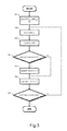
- the SA applied to the iterative optimization of handover parameters is depicted in fig. 5 .
- a new state S' is selected.
- p exp(- ⁇ /T) is the probability the new state S' is accepted if the objective function has increased.
- step 506 the temperature is adjusted.
- step 507 if the stopping conditions are met, then current state S can be frozen. It is the optimum solution; else, go to step 502.
- the second stage can also be initialized by any other method, heuristically initial configuration or simply randomly. This will impact the convergence duration.
- UMTS Universal Mobile Terrestrial System
- GSM Global System for Mobility
- the distribution of the functional units depicted in fig. 2 over the various network elements may vary from one technology to the other.
- the radio resource controller 140 and related handover configuration agent 150 typically form part of an RNC for UMTS, or of a BSC for GSM.
- the signal characteristics that are being measured by the mobile stations and that are used by the handover optimization algorithm may also vary from one technology to the other. For instance, the Receive Signal 1 code Power (RSCP) or Reference Signal Receive Quality (RSRQ) may be used in lieu of the present RSRP.
- RSCP Receive Signal 1 code Power
- RSRQ Reference Signal Receive Quality
- the term 'coupled' should not be interpreted as being restricted to direct connections only.
- the scope of the expression 'a device A coupled to a device B' should not be limited to devices or systems wherein an output of device A is directly connected to an input of device B, and/or vice-versa. It means that there exists a path between an output of A and an input of B, and/or vice-versa, which may be a path including other devices or means.
- DSP digital signal processor
- ASIC application specific integrated circuit
- FPGA field programmable gate array
- Other hardware, conventional and/or custom, such as read only memory (ROM), random access memory (RAM), and non volatile storage, may also be included.
Landscapes
- Engineering & Computer Science (AREA)
- Computer Networks & Wireless Communication (AREA)
- Signal Processing (AREA)
- Mobile Radio Communication Systems (AREA)
Abstract
Description
- The present invention relates to mobility within a mobile or wireless network, and more specifically to the configuration of handover parameters used for detecting that a given neighboring cell fulfills a given handover condition within a given serving cell.
- Supporting mobility with steady quality is a requirement for 4th generation (4G) networks and beyond. To this end, handover is a key Radio Resource Management (RRM) technique that ensures service continuity while a user is moving across radio cells by changing attachment of a user terminal from one cell to another more suitable cell, thereby enhancing the user experience and the overall network performances (lower power consumption, lower radio interference, etc).
- However, the handover procedure is performed upon triggering conditions which have to be properly configured and optimized so that target Quality of service (Qos) and Quality of Experience (QoE) objectives are achieved.
- Indeed, an efficient design and optimization of the handover procedure shall meet the following requirements:
- minimizing Radio Link Failures (RLF) and call drops during handover procedures; while
- minimizing the number of unnecessary handovers; and
- maximizing the duration of user connection to the best cell.
- To illustrate this, let's consider the two following scenarios.
- A handover that is triggered too lately leads to RLF in the source cell: the user keeps attached to its serving cell while moving outside the cell radio coverage.
- conversely, a handover that is launched too early leads to erroneous decisions: useless handover decision to a new cell, and then reconnection to the original serving cell (ping-pong handovers), or erroneous selection of a new target cell.
- So, it is easy to understand that it is crucial to achieve a fine-adjustment of the handover parameter values in order to trigger a handover when appropriate, and towards a properly selected target cell. When appropriate and towards a properly selected target cell means that the following trade-off between the following - and somehow contradictory - goals is met: minimizing the duration before detection, that is to say the duration between the instant of an effective change (e.g., target cell gets offset-better than current serving cell) and the decision to trigger a handover, while minimizing false handover alarms (i.e., erroneous handover decisions).
- In 3rd Generation Partnership Project (3GPP) standard development, the Mobility Robustness Optimization (MRO) feature aims at first detecting and counting RLFs due to handovers, then to find solutions to reduce handover performances degradation.
- MRO distinguishes three handover failure cases:
- [Too Late HO] A connection failure occurs in the source cell before the handover was initiated, or during a handover; the User Equipment (UE) attempts to re-establish the radio link connection in the target cell (if handover was initiated) or in a cell that is not the source cell (if handover was not initiated).
- [Too Early HO] A connection failure occurs shortly after a successful handover from a source cell to a target cell, or during a handover; the UE attempts to re-establish the radio link connection in the source cell.
- [HO to Wrong cell] A connection failure occurs shortly after a successful handover from a source cell to a target cell or during a handover; the UE attempts to re-establish the radio link connection in a cell other than the source cell and the target cell.
- In 3GPP Long Term Evolution (LTE) standard, handover is performed as following. The user performs periodic measurements, typically filtered Reference Signal Received Powers (RSRP) on the serving (Ms) and neighbor cells (Mn). When a given handover condition is met (typically an A3 event) for a particular neighboring cell, the UE reports its measurements to the serving cell, which eventually decides to trigger or not a handover based on the user's recommendations.
- Basically, A3 event reporting by the UE is triggered if at least one neighbor cell becomes better than the serving cell by a configurable offset value. Handover reporting measurement by the UE is triggered if the condition is met for a minimal configurable duration or Time-To-Trigger (TTT).
- Particularly in dense networks of small cells (but not only), it is important to reduce the time for operators to manage a wide set of cell and handover parameters in particular. It is also worthwhile to state that the automatic configuration and optimization of cell and handover parameters is a key feature for 4G networks, especially for dense networks.
- We propose a solution to enable each cell, in a distributive and fully autonomous way, to jointly adjust the major handover parameters so as to achieve a near-optimal trade-off between minimizing the probability of late handover decisions (rate of Too Late HO) while minimizing the risk of false alarms (rate of Too Early HO and HO to Wrong cell).
- To the best of our knowledge, there is no solution to jointly optimize the handover parameters.
- In the article entitled " A Cost-based Adaptive Handover Hysteresis scheme to Minimize the Handover Failure Rate in 3GPP LTE system" from D-W Lee, G-T Gil and D-H Kim, and published in July 2010 in the EURASIP Journal on Wireless Communications and Networking, the hysteresis parameter is iteratively adjusted (increased/decreased) so as to minimize handover failure rate, accounting for neighbor cells load, the user speed or the traffic type.
- In the conference paper entitled " Handover Parameter optimization in L TE self-organizing Networks" from T. Jansen, I. Balan & al published in September 2010 during the IEEE 72nd Vehicular Technology Conference in Ottawa (canada), the operating point (Hysteresis or HO Margin, Time-To-Trigger) is adjusted in an iterative way in order to minimize handover related QoS like handover failure ratio, ping-pong (oscillation) rates or call dropping rates. The adjustment path is set-up according to the experienced performances compared to target ones. Although practical, the empirical solutions lack theoretical basis for solving the trade-off introduced here above.
- In the conference paper entitled "A Novel Self-optimizing Handover Mechanism for Multi-Service provisioning in LTE-Advanced" from H. zhang, X. Wen & al published in 2009 during Research challenges in Computer Science ICRCCS '09 conference, the authors tune hysteresis, Time-To-Trigger and filtering parameters so that the number of handovers gets close to the number of cells boundary crossings. Though novel, this approach does not rely on handover counters specified by 3GPP through MRO feature, which makes its application in real networks difficult.
- In the lecture notes entitled "Distributed Self-optimization of Handover for the Long Term Evolution" from A. schröder, H. Lundqvist and G. Nunzi published in 2008 in computing Science, Volume 5343/2008, p. 281-286, the authors presents a trial and error loop method to optimize one or more handover parameters.
- It is an object of the present invention to provide an efficient and autonomous way for determining optimal values for handover parameters.
- In accordance with a first aspect of the invention, a method for adjusting handover parameters used for handover detection within a given serving cell comprises, for respective ones of a plurality of mobile stations served by the serving cell, gathering measurement samples of the serving cell and of a respective neighboring cell carried out by a respective mobile station at successive time instances, and determining delta values indicative of the time-indexed difference between respective ones of the measurement samples of the serving cell and corresponding ones of the measurement samples of the neighboring cell. The method further comprises determining near-optimal values for the handover parameters by statistical characterization of the ensembles of delta values for the plurality of mobile stations.
- In accordance with another aspect of the invention, a configuration agent for adjusting handover parameters used for handover detection within a given serving cell is adapted, for respective ones of a plurality of mobile stations served by the serving cell, to gather measurement samples of the serving cell and of a respective neighboring cell carried out by a respective mobile station at successive time instances, and to determine delta values indicative of the time-indexed difference between respective ones of the measurement samples of the serving cell and corresponding ones of the measurement samples of the neighboring cell. The configuration agent is further adapted to determine near-optimal values for the handover parameters by statistical characterization of the ensembles of delta values for the plurality of mobile stations.
- The configuration agent may form part of either a radio access node, such as an evolved NodeB (eNB), a radio access controller, such as a Base Station Controller (BSC) or a Radio Network Controller (RNC), or a network manager.
- In one embodiment of the invention, the near-optimal values are input to an iterative closed-loop optimization algorithm in order to determine optimal values for the handover parameters.
- In one embodiment of the invention, the iterative closed-loop optimization algorithm is based on a Simulated Annealing (SA) algorithm.
- In one embodiment of the invention, the measurement samples are indicative of the respective strengths of pilot signals received by the respective mobile stations from the respective serving and neighboring cells.
- In one embodiment of the invention, the measurement samples are indicative of the respective qualities of pilot signals received by the respective mobile stations from the respective serving and neighboring cells.
- In one embodiment of the invention, the plurality of mobile stations belongs to a particular speed class, and the near-optimal values for the handover parameters are determined on per speed class basis.
- In one embodiment, the statistical characterization of the ensembles of delta values for the plurality of mobile stations involves the characterization of variances of the delta values for respective ones of the plurality of mobile stations over varying time windows.
- This embodiment is particularly helpful for determining the near-optimal values for TTT and/or offset handover parameters.
- In one embodiment of the invention, the method further comprises, for respective ones of the plurality of mobile stations, and from a given time index onwards, estimating variance values over a time-window of K successive delta values for respective increasing K values, and determining a minimum time-window length beyond which the so-determined variance values lies within a given small interval. The method further comprises determining a Time-To-Trigger TTT value, during which measurement samples of the serving cell and a given target cell shall fulfill the handover condition before triggering a handover, by statistical characterization of the so-determined minimum time-window lengths for the plurality of mobile terminals.
- Similarly, the configuration agent is further adapted, for respective ones of the plurality of mobile stations, and from a given time index onwards, to estimate variance values over a time-window of K successive delta values for respective increasing K values, and to determine a minimum time-window length beyond which the so-determined variance values lies within a given small interval. The configuration agent is further adapted to determine a Time-To-Trigger TTT value, during which measurement samples of the serving cell and a given target cell shall fulfill a given handover condition, by statistical characterization of the so-determined minimum time-window lengths for the plurality of mobile terminals.
- In one embodiment of the invention, the so-determined TTT value is such that a given proportion of the so-determined minimum time-window lengths for the plurality of mobile stations are lower than or equal to the TTT value.
- In one embodiment of the invention, the method further comprises determining a nominal variance value by statistical characterization of the so-estimated variance values, and inputting the so-determined nominal variance value, along with a first upper bound for a handover detection time and a second upper bound for a false handover detection rate, to a Page Hinkley statistical test so as to determine an offset value whereby the target cell shall be measured offset-better than the serving cell for the handover condition to be fulfilled.
- Similarly, the configuration agent is further adapted to determine a nominal variance value by statistical characterization of the so-estimated variance values, and inputting the so-determined nominal variance value, along with a first upper bound for a handover detection time and a second upper bound for a false handover detection rate, to a Page Hinkley statistical test so as to determine an offset value whereby the target cell shall be measured offset-better than the serving cell for the handover condition to be fulfilled.
- In one embodiment of the invention, the nominal variance value is determined such that a further given proportion of the variance values estimated for the plurality of mobile stations over time-windows of lengths equal to the TTT value are lower than or equal to the nominal variance value.
- In one embodiment of the invention, the determination of the offset value is instantiated on a per neighboring cell basis, and the first upper bound is adjusted based on an inter-site distance between the serving cell and a given neighboring cell and based on the particular speed class.
- The proposed solution relies on theoretical framework to jointly estimate the handover parameters based on handover counters specified by the MRO feature in 3GPP specification. This has the advantage to enable easy and direct implementation in real networks.
- More specifically, the joint optimization of the following HO parameters is targeted:
- TTT parameter is directly linked to the performances of the L3 filtering operation. Indeed, the TTT criterion checks that the condition on L3 filtered measurements is persistent over a time window of duration TTT.
- Offset parameter has to be configured so as to minimize the delay R before the effective triggering of handovers, while avoiding useless or erroneous handover attempts.
- We propose in this invention a procedure aimed at a joint optimization and set up of TTT and Offset handover parameters. The proposed scheme here relies on a two-stage procedure where the first stage is a learning (or sensing) phase to find out near-optimal values for the handover parameters by statistical characterization of the measurement samples gathered from the mobile stations, and the second stage is an optimization stage to fine-tune the handover parameter values by means of an iterative closed-loop algorithm, starting from the near optimal values output from the first stage. However, in each step, only one parameter is considered, which makes the optimization less efficient in real networks.
- The above and other objects and features of the invention will become more apparent and the invention itself will be best understood by referring to the following description of an embodiment taken in conjunction with the accompanying drawings wherein:
-
fig. 1 represents a part of a mobile network as per the LTE standard; -
fig. 2 represents a radio access node as per the present invention; -
fig. 3 represents an overview of the algorithm that is used for determining optimal values for the handover parameters; -
fig. 4A represents a flow chart of computed variance values as a function of the time-window length; -
fig. 4B represents a flow chart of the cumulative distribution function of the optimal TTT values determined for the respective Ues; and -
fig. 5 represents an overview of the SA algorithm that is used for fine-tuning the handover parameter values. - There is seen in
fig. 1 apart 1 of an Evolved Radio Access Network (E-RAN) and of an Evolved Packet Core (EPC) comprising the following network elements: - eNBs 10;
- an
MME 20; - a Serving Gateway (S-GW) 30;
- a Packet Data Network (PDN) Gateway (P-GW) 40; and
-
UEs 60. - The eNBs 10 are coupled to the
MME 20 through an S1-MME interface, and to the S-GW 30 through an S1-U interface. The S-GW 30 is further coupled to the P-GW 40 through an S5 interface. The P-GW 40 is further coupled to aPDN 50 through an SGi interface. The neighboring eNBs 10 establish neighbor relationships through an X2 interface. - The eNBs 10 operate macro, micro or pico cells with a radio coverage area ranging from a few kilometers up to a few tens meters. The eNBs 10 are configured to set up and operate radio communication channels (i.e., a set of downlink and uplink traffic radio resources) with the
UEs 60 through a Uu radio interface. - More noticeably, each of the eNBs 10 hosts the following functions:
- Radio Resource Control (RRC): radio bearer control, radio admission control, connection mobility control, dynamic allocation of resources to UEs in both uplink and downlink (scheduling);
- Routing of user-plane data towards the S-GW;
- Scheduling and transmission of paging messages from the MME;
- Scheduling and transmission of broadcast information;
- Measurement and measurement reporting configuration for mobility and scheduling.
- The
MME 20 hosts the following functions: - Non Access Stratum (NAS) signaling;
- Idle mode UE reachability, including control and execution of paging retransmission;
- Tracking Area (TA) list management for UE in idle and active mode;
- S-GW selection;
- MME selection for inter-MME handovers;
- Roaming;
- Authentication;
- Bearer management functions including dedicated bearer establishment.
- The S-
GW 30 hosts the following functions: - Local mobility anchor point for inter-eNB handover;
- E-UTRAN idle mode downlink packet buffering and initiation of network triggered service request procedure;
- Lawful interception;
- Packet routing and forwarding;
- Transport level packet marking in the uplink and the downlink;
- downlink and uplink charging per UE, PDN, and Quality of Service (Qos) class Identifier (QCI).
- The P-
GW 40 hosts the following functions: - UE IP address allocation and IP anchor point;
- Per-user based packet filtering (e.g., by means of deep packet inspection);
- Lawful interception;
- Downlink and uplink service level charging, gating and rate enforcement.
- There is seen in
fig. 2 further details about an eNB 100 as per the present invention, and configured to operate one or more serving cells. - The eNB 100 comprises the following functional blocks:
- one or more transceivers 110, each one comprising a digital base-band unit 111 (or BBU) and an analog band-pass unit 112 (or ANA);
- a coupling unit 120 (or COUP);
- a network termination unit 130 (or NTU);
- a radio resource controller 140 (or RRC);
- a handover configuration agent 150 (or HO_CFG) for determining optimal values for the handover parameters to be passed to the UEs and/or to the
radio resource controller 140 for handover condition detection; - a UE speed characterization unit 160 (or UE_SPEED);
- a cell characterization unit 170 (or CELL_CHAR); and
- an
antenna 180. - The
network termination unit 130 is coupled to the digital base-band unit 111, the digital base-band unit 111 is coupled to the analog band-pass unit 112, the analog band-pass unit 112 is coupled to thecoupling unit 120, and thecoupling unit 120 is coupled to an external orinternal antenna 180. Theradio resource controller 140 is coupled to the transceivers 110. Thehandover configuration agent 150 is coupled to theradio resource controller 140. The UEspeed characterization unit 160 and thecell characterization unit 170 are coupled to thehandover configuration agent 150. - The transceivers 110 are configured to establish and operate radio communication channels with UEs under control of the
radio resource controller 140. - The digital base-band unit 111 is for digitally processing the received and transmit data symbols. The digital base-band unit 111 implements the necessary protocol suites for issuing, terminating or relaying data and control packets.
- The analog band-pass unit 112 is for modulating, amplifying and shaping the transmit signal that ultimately feds the
antenna 180, and for filtering, amplifying with as little noise as possible and demodulating the received signal from theantenna 180. The analog band-pass 112 unit can be merged with the digital base-band unit, or can be moved closer to the antenna in a so-called Remote Radio Head-end (RRH) configuration. - The
coupling unit 120 is for combining and passing the transmit signals from the transceivers 110 towards theantenna 180, and for dispatching the receive signal from theantenna 180 towards the transceivers 110. - The
network termination unit 130 accommodates the appropriate Medium Access Control (MAC) and Physical transport (PHY) layers for communication through a PDN, as well as some frame dispatching logic for routing the incoming/outgoing frames towards the appropriate Input/output (I/O) ports. - The
radio resource controller 140 is for assigning and managing downlink and uplink radio resources used by the transceivers 110 and the respective UEs for radio communication over the air interface, that is to say a set of time and/or frequency resources assigned to a serving cell operated by the eNB 100 for transport of user or control traffic within that serving cell. More noticeably, theradio resource controller 140 makes decisions for outgoing handovers from the current serving cell towards a more suitable neighboring cell based on the UE measurement reports. - The
radio resource controller 140 is for further configuring an ad-hoc measurement policy within the one or more serving cells operated by the eNB 100 (see "Meas_Policy(CS)" infig. 2 ). - More specifically, the UEs are configured with a trigger criteria for reporting the cell measurements to the eNB 100. In particular, during a preliminary sensing phase, the UEs are configured to periodically report the receive power or quality of the serving cell and of one or more best neighboring cells at a given reporting interval. When the learning phase completes and enough measurement samples have been gathered for good statistical characterization, the UEs are then configured to trigger measurement reporting only upon fulfillment of a particular handover condition, as typical in LTE networks.
- The cell measurement data gathered during the sensing phase are held in a local data repository for further retrieval by the handover configuration agent 150 (see "M(i,CS,k); M(i,CN,k)" in
fig. 2 ), along with further measurement context data such as the UE identity, the UE speed category, the UE location, the time-of-the-day the measurements took place, the user device manufacturer, etc. - The UEs are also configured with one or more handover conditions for detecting that a given neighboring cell is a more suitable candidate cell for radio communication.
- For instance, the UEs can be configured with an A3 handover condition (neighboring becomes offset better than serving) that comprises an hysteresis value HYS, a TTT value, a generic offset value OFF, and possibly cell-specific offset values OCN to manage specificities towards particular neighboring cells. The values of these parameters are directly obtained from the
handover configuration agent 150. A so-configured UE reports an A3 measurement event whenever the received power of a reference signal from a neighboring cell is measured as being better than the receive power of a reference signal from the serving cell by the offset amount OFF - possibly increased or decreased by the cell individual offset OCN - and for TTT seconds. The hysteresis HYS prevents excessive toggling between the A3 entering and leaving condition. - The Entering and Leaving A3 conditions are defined by the following inequalities:


Wherein Mn (respectively Ms) denotes the Layer 3 (L3) filtered Reference Signal Receive Power (RSRP) from the neighbor (respectively serving) cell. - The
handover configuration agent 150 is for processing the UE measurement reports so as to determine optimal values for handover parameters used for handover detection within the one or more serving cells operated by the eNB 100. The so-determined handover parameter values are returned to theradio resource controller 140 for proper configuration of the handover conditions (see "TTT(CS); OFF(CS); OCN(CS,CN)" infig. 2 ). - The UE
speed characterization unit 160 is configured to characterize a particular UE as belonging to a particular speed class, e.g. low/medium/high-speed class (LS/MS/HS) by comparing the UE speed to respective speed thresholds. - The UE
speed characterization unit 160 may determine the UE speed category according to first speed information supplied by the UE (e.g., as estimated from GPS positioning data), and/or according to second speed information determined by the eNB 100 (e.g., the Doppler frequency shift is indicative of the radial UE speed with respect to the eNB 100), and/or according to third speed information relayed by a source eNB during an incoming handover procedure (e.g., as derived from the time spent in previous visited cells, or as explicitly encoded by the source eNB). - The respective UE speed categories are passed to the
handover configuration agent 150 as possible inputs to the optimization algorithm (see "UEi=LS/MS/HS" infig. 2 ). - The neighboring
cell characterization unit 170 is for determining Inter Site Distance (ISD) values between the one or more serving cells operated by the eNB 100 and their respective neighboring cells. The ISD values are either derived by characterization of the radio communication environment (possibly involving the UEs), or are field engineering data obtained from a network manager or from a network planning tool. The respective ISD values are passed to thehandover configuration agent 150 as possible inputs to the optimization algorithm (see "ISD(CS,CN)"infig. 2 ). -
Fig. 3 represents an overall description of the algorithm that is used within thehandover configuration agent 150 for determining optimal values for the handover parameters, namely the handover parameters TTT and OFF. - The output of the first stage (see
step 301 infig. 3 ) are the near-optimal values TTTNO and OFFNO for the handover parameters, which are the input of the optimisation phase instage 2. - The second stage aims at fine-tuning the near-optimal 1 values TTTNO and OFFNO to yield optimal values TTTo and OFFo for the handover parameters (see
step 302 infig. 3 ). - A condition (alarm) can be added at this level to provoke a return to
stage 1 when needed, e.g. when the performances in term of MRO counters are below a predefined threshold (seestep 303 infig. 3 ). - [STAGE 1] The UEs perform L3-filtered RSRP measurements and report them to the serving eNB operating the serving cell they are attached to.
- The latter processes the measurements and derives the initial joint configuration (TTT,OFF). Indeed, a joint configuration is necessary to capture the inter-dependency between these two parameters.
- Optionally, the processing of the UE measurements can be made depending on the speed class of the UE (e.g., Small, Medium or High Speed classes) and/or the ISD, that is to say the distance separating the antenna sites of the serving and neighboring cells.
- Intuitively, OFF shall account for the variance of the measurements. For example, small OFF values with strong fluctuations of measurements is likely to lead to false handover alarms.
- Added to this, TTT is the duration of persistence of the handover condition. When the handover entering condition is true for one time sample, the condition has to remain verified even if measurements fluctuate. So, TTT is directly linked to how the measurements are spread around their mean values: the variance.
- In the present invention, OFF is computed from the variance of measurements that are estimated over the TTT window size. The latter corresponds to the minimum duration over which the variance is stabilized to a steady value.
- [TTT configuration in stage 1] Let

- Let M(i,CS,k) and M(i,CN,k) denote the L3-filtered RSRP measurements carried out by a given UE UEi for the serving cell CS and a neighbor cell CN (out of all the neighboring cells of the serving cell CS) at successive time instances k.
- Let Δ(i,CN,k) denote the time-indexed difference between measurement samples of the serving cell CS and corresponding measurement samples of the neighboring cell CN as reported by the UE UEi:

- Let VarκΔ be the variance of the difference Δ(i,CN,k) estimated over a time window comprising K measurement samples from a reference time index k0 onwards, wherein K denotes a positive integer value taken from the range [Kmin;Kmax].
- A possible unbiased estimator for the variance VarκΔ is:

wherein Δk denotes the mean Δ value over K successive Δ values:
- Let TTT(i,CN) be the minimum K value beyond which the variance VarκΔ lies within a given small interval around its asymptotic value. This is illustrated in
fig. 4A : TTT(i,CN) is the minimum time window beyond which the variance VarκΔ gets substantially constant. - The aforementioned TTTi computation is re-iterated for further neighboring cells as measured by the UE UEi, as well as for further attached UEs at various geographical positions within the serving cell CS, thereby yielding a statistical ensemble {TTT(-i,CN)}i,CN.
- The near-optimal value TTTNO for TTT parameter is then derived from the statistics over the statistical ensemble {TTT(i,CN)}i,CN. For example, and as illustrated in
fig. 4B , it is obtained from the Cumulated Density Function (cdf) at 90%:
- [offset configuration in stage 1] The proposed algorithm relies on an interesting property of one change detection in a Page Hinkley test. Indeed, the Page Hinkley test detects abrupt changes in signal or systems with applications such as monitoring (detection of changes in vibrating modes which diagnosis systems anomaly), detection of bordering lines in video, segmentation in speech with detection of start and end of events.
- The proposed algorithm applies this change detection test to the handover detection. Indeed, handover decision should be ideally triggered as soon as the signal received from the neighbor cell exceeds the signal from the serving cell by a given handover margin. Change detection comes to detecting a change in mean values of the difference between M(i,CS,k) and M(i,CN,k).
- We recall that we aim at optimizing the two conflicting performance objectives:
- minimizing the delay R before actually detecting the change (delay separating the effective change and the decision time); while
- maximizing the duration F between two False Alarms.
- In practice, we target tests that are optimal in that they minimize R for a given F value.
- The Page Hinkley method is optimal in that sense, with the powerful and quite simple following property:

and wherein σ2 denotes a nominal variance value of the observations supposed invariant before or after change. - In the context of handover, R is the delay separating the instant the neighboring cell is detected offset-better than the serving cell and the instant the handover decision is made. Minimizing R comes to minimizing the risk of Too Late HO; and maximizing F comes to minimizing the risk for Too Early HO and HO to Wrong Cells.
- The near-optimal value OFFNO for OFF parameter is then derived from Equation (6) with the simple formula:

wherein FHO denotes the target maximum duration that can be tolerated between two HO failures of type HO Too early or HO To wrong cells,
and wherein RHO denotes the upper bound on the detection duration (distance from the frontier between 2 cells and the actual Handover Decision) that shall occur before the users cross the cell boundary (otherwise handover fails because triggered too lately). - RHO is either set by the operator in such a way that users have completed their handover before crossing the cell boundary, or is estimated as the probable duration from the frontier between the cells and the cell boundary.
- σ2 is set to a nominal variance value derived from the statistics of the previously computed varκA with K being set to the generic TTT value. For instance, σ2 is set as the CDF at 90% of the statistical ensembles {VarTTTΔ(i, CN)}i,CN .
- Inter-dependence between OFF and TTT parameters is thus captured by the fact that OFF is computed from the variance over TTT window: TTT is derived from the variance of the measurements on a set of possible window sizes; this variance estimated over TTT is then injected as input to an Offset module for the estimation of OFF parameter.
- The determination of TTT parameter can be instantiated on a per speed class basis, in which case the ensemble

- Similarly, the determination of the offset parameter can be instantiated on per speed class basis and on per neighbor cell basis. Only the measurements of a given neighboring cell and from UEs of a given speed class are now considered. The generic OFF value is then set to a default value, and one adjusts the actual offset value used for a given neighboring cell by playing with the cell specific offset parameter OCN (positive or negative value).
- The ISD between the serving cell and the given neighboring cell may also be considered for appropriately adjusting RHO value. Indeed, a user terminal that moves at a high speed from a serving cell to a neighbor cell stays a short time in the critical area (the overlapping area). The duration for deciding about a handover shall be short, and so shall be RHO.
- A generic formulation of the Page Hinkley test is now set forth.
- Let {y1, ..., yK} denote K observation samples of a signal. The objective is to detect if there has been a change in the sequence of observations. Let yr denote the sample corresponding to this change.
- Let p0 denote the Probability Density Function (PDF) before the change, and let p1 denote the PDF after the change.
- This can be written as:
- H0 (no change)
- yk ∈ p0 ; 1 ≤ k ≤ K,
- H1 (change at sample r)
- yk ∈ p0 ; 1 ≤ k ≤ r-1, and yk ∈ p1 ; r ≤ k ≤ K.
- The general decision rule based on Maximum Likelihood principles can be derived in the following way:

- This test is then applied to the detection of a jump in the mean value from µ0 to µ1 for normal observations with fixed variance. Let:

- If we consider a sequential process with observations from
index 1 to sliding index K (instead of fixed K), it is demonstrated that the detection of jump in the mean of the signal occurs if:
- Let the observations sequence set be the time-indexed difference between the RSRP of the serving cell CS and the RSRP of the neighbor cell CN:

- Handover is detected if equation (11) is verified with µ 0 = 0 and ν is the handover offset OFF.
- [STAGE 2] The second stage is a closed-loop optimization algorithm initialized with the parameter values (TTTNO,OFFNO) as computed during the first stage. The idea consists in adjusting (incrementing or decrementing) the parameter values (TTTNO,OFFNO) depending on the experienced MRO counters.
- A possible implementation for the second stage is set forth here below based on the Simulated Annealing (SA) approach.
- SA is a meta heuristic technique for solving a global optimization problem. It consists in iteratively perturbing some sub optimal solution towards a better one. The main advantage of SA is that it can deal with non linear, non differentiable problems with many local optima and requires very few assumptions.
- SA is based on an analogy with the annealing process in metallurgy. Annealing consists in a controlled process of heating then cooling before freezing the metal in order to achieve the desired material properties: hardness or flexibility properties. By analogy, in optimization by simulated annealing, when the temperature is high, large bounces from one state to another is tolerated. When temperature gets low, less and less random movement from one state to another is tolerated and the system is stabilized to the final frozen state (the optimal one).
- In the literature, optimization by SA is often compared to a bouncing ball that can bounce over mountains from valley to valley. At the beginning of the optimization process by SA, high temperatures lead to large bounces over mountains and valleys. When the temperature decreases, the ball cannot bounce high then it is trapped in a smaller range of valleys, around the optimum.
- During the high temperature phase, the solution moves out of (escape from) local optima. Fine search of the optima is achieved at lower temperature.
- The SA applied to the iterative optimization of handover parameters is depicted in
fig. 5 . - In
step 501, he algorithm is initialized with state SO=(TTTNO,OFFNO) as determined by the first stage. Temperature is set-up to a high value To. The temperature cooling rate is r. - The objective function is f=HOL+HOE&w (respectively HO Too late ratio and HO Too Early plus HO To Wrong cell ratio)
- In
step 502, a new state S' is selected. Optionally, the state selection process shall account for performances obtained with S state, i.e. HOL(S) and HOE&W(S) ratios. For example: If HOL(S) > Max_Threshold then S'=S-(λ,β). - In
step 503, the difference between the objective function of the new state S' and the objective function of the former state S is determined:
- In
step - In
step 506, the temperature is adjusted. Many variants of cooling schedule can be envisaged, such as T'= rT. - In
step 507, if the stopping conditions are met, then current state S can be frozen. It is the optimum solution; else, go to step 502. - The second stage can also be initialized by any other method, heuristically initial configuration or simply randomly. This will impact the convergence duration.
- Although the above description focuses on LTE networks and related architecture and terminology, it may similarly applies to other mobile technologies such as Universal Mobile Terrestrial System (UMTS) and Global System for Mobility (GSM). The distribution of the functional units depicted in
fig. 2 over the various network elements may vary from one technology to the other. For instance, theradio resource controller 140 and relatedhandover configuration agent 150 typically form part of an RNC for UMTS, or of a BSC for GSM. The signal characteristics that are being measured by the mobile stations and that are used by the handover optimization algorithm may also vary from one technology to the other. For instance, the ReceiveSignal 1 code Power (RSCP) or Reference Signal Receive Quality (RSRQ) may be used in lieu of the present RSRP. - It is to be noticed that the term 'comprising' should not be interpreted as being restricted to the means listed thereafter. Thus, the scope of the expression 'a device comprising means A and B' should not be limited to devices consisting only of components A and B. It means that with respect to the present invention, the relevant components of the device are A and B.
- It is to be further noticed that the term 'coupled' should not be interpreted as being restricted to direct connections only. Thus, the scope of the expression 'a device A coupled to a device B' should not be limited to devices or systems wherein an output of device A is directly connected to an input of device B, and/or vice-versa. It means that there exists a path between an output of A and an input of B, and/or vice-versa, which may be a path including other devices or means.
- The description and drawings merely illustrate the principles of the invention. It will thus be appreciated that those skilled in the art will be able to devise various arrangements that, although not explicitly described or shown herein, embody the principles of the invention and are included within its scope. Furthermore, all examples recited herein are principally intended expressly to be only for pedagogical purposes to aid the reader in understanding the principles of the invention and the concepts contributed by the inventor(s) to furthering the art, and are to be construed as being without limitation to such specifically recited examples and conditions. Moreover, all statements herein reciting principles, aspects, and embodiments of the invention, as well as specific examples thereof, are intended to encompass equivalents thereof.
- The functions of the various elements shown in the figures may be provided through the use of dedicated hardware as well as hardware capable of executing software in association with appropriate software. When provided by a processor, the functions may be provided by a single dedicated processor, by a single shared processor, or by a plurality of individual processors, some of which may be shared. Moreover, a processor should not be construed to refer exclusively to hardware capable of executing software, and may implicitly include, without limitation, digital signal processor (DSP) hardware, network processor, application specific integrated circuit (ASIC), field programmable gate array (FPGA), etc. Other hardware, conventional and/or custom, such as read only memory (ROM), random access memory (RAM), and non volatile storage, may also be included.
Claims (16)
- A method for adjusting handover parameters (TTT; OFF) used for handover detection within a given serving cell (CS), wherein the method comprising, for respective ones of a plurality of mobile stations (UE1 .. UEN) served by the serving cell, gathering measurement samples (M(i,CS,k); M(i,CN,k)) of the serving cell and of a respective neighboring cell (CN) carried out by a respective mobile station (UEi) at successive time instances (k), and determining delta values (Δ(-i,CN,k)) indicative of the time-indexed difference between respective ones of the measurement samples of the serving cell and corresponding ones of the measurement samples of the neighboring cell,
and wherein the method further comprises determining near-optimal values (TTTNO; OFFNO) for the handover parameters by statistical characterization of the ensembles of delta values for the plurality of mobile stations. - A method according to claim 1, wherein the method further comprises inputting the near-optimal values to an iterative closed-loop optimization algorithm in order to determine optimal values (TTTo; OFFo) for the handover parameters.
- A method according to claim 2, wherein the iterative closed-loop optimization algorithm is based on a simulated annealing algorithm.
- A method according to claim 1, wherein the measurement samples are indicative of the respective strengths of pilot signals received by the respective mobile stations from the respective serving and neighboring cells.
- A method according to claim 1, wherein the measurement samples are indicative of the respective qualities of pilot signals received by the respective mobile stations from the respective serving and neighboring cells.
- A method according to claim 1, wherein the plurality of mobile stations belongs to a particular speed class (LS; MS; HS), and wherein the near-optimal values for the handover parameters are determined on per speed class basis.
- A method according to any of the preceding claims, wherein the statistical characterization of the ensembles of delta values for the plurality of mobile stations involves the characterization of variances of the delta values for respective ones of the plurality of mobile stations over varying time windows.
- A method according to claim 7, wherein the method further comprises, for respective ones of the plurality of mobile stations, and from a given time index (k0) onwards, estimating variance values (VarKΔ) over a time-window of K successive delta values for respective increasing K values, and determining a minimum time-window length (TTT(i,CN)) beyond which the so-determined variance values lies within a given small interval,
and wherein the method further comprises determining a Time-To-Trigger TTT value (TTTNO), during which measurement samples of the serving cell and a given target cell shall fulfill a given handover condition, by statistical characterization of the so-determined minimum time-window lengths for the plurality of mobile stations. - A method according to claim 8, wherein the so-determined TTT value is such that a given proportion of the so-determined minimum time-window lengths for the plurality of mobile stations are lower than or equal to the TTT value.
- A method according to claim 8, wherein the method further comprises determining a nominal variance value by statistical characterization of the so-estimated variance values, and inputting the so-determined nominal variance value, along with a first upper bound for a handover detection time and a second upper bound for a false handover detection rate, to a Page Hinkley statistical test so as to determine an offset value (OFFNO) whereby the target cell shall be measured offset-better than the serving cell for the handover condition to be fulfilled.
- A method according to claim 10, wherein the nominal variance value is determined such that a further given proportion of the variance values estimated for the plurality of mobile stations over time-windows of lengths equal to the TTT value are lower than or equal to the nominal variance value.
- A method according to claim 6 and 10, wherein the determination of the offset value is instantiated on a per neighboring cell basis,
and wherein the first upper bound is adjusted based on an inter-site distance (ISD(CS,CN)) between the serving and a given neighboring cell and on the particular speed class. - A configuration agent (150) for adjusting handover parameters (TTT; OFF) used for handover detection within a given serving cell (CS), wherein the configuration agent is adapted, for respective ones of a plurality of mobile stations (UE1 .. UEN) served by the serving cell, to gather measurement samples (M(i,CS,k); M(i,CN,k)) of the serving cell and of a respective neighboring cell (CN) carried out by a respective mobile station (UEi) at successive time instances (k), and to determine delta values (Δ(i,CN,k)) indicative of the time-indexed difference between respective ones of the measurement samples of the serving cell and corresponding ones of the measurement samples of the neighboring cell,
and wherein the configuration agent is further adapted to determine near-optimal values (TTTNO; OFFNO) for the handover parameters by statistical characterization of the ensembles of delta values for the plurality of mobile stations. - A radio access node (100) comprising a configuration agent according to claim 13.
- A radio access controller comprising a configuration agent according to claim 13.
- A network manager comprising a configuration agent according to claim 13.
Priority Applications (4)
| Application Number | Priority Date | Filing Date | Title |
|---|---|---|---|
| EP12306292.9A EP2723123A1 (en) | 2012-10-18 | 2012-10-18 | Autonomous determination of optimal values for handover parameters |
| US14/436,279 US9572071B2 (en) | 2012-10-18 | 2013-10-15 | Autonomous determination of optimal values for handover parameters |
| PCT/EP2013/071498 WO2014060396A1 (en) | 2012-10-18 | 2013-10-15 | Autonomous determination of optimal values for handover parameters |
| CN201380054730.3A CN104756546A (en) | 2012-10-18 | 2013-10-15 | Autonomous determination of optimal values for handover parameters |
Applications Claiming Priority (1)
| Application Number | Priority Date | Filing Date | Title |
|---|---|---|---|
| EP12306292.9A EP2723123A1 (en) | 2012-10-18 | 2012-10-18 | Autonomous determination of optimal values for handover parameters |
Publications (1)
| Publication Number | Publication Date |
|---|---|
| EP2723123A1 true EP2723123A1 (en) | 2014-04-23 |
Family
ID=47221263
Family Applications (1)
| Application Number | Title | Priority Date | Filing Date |
|---|---|---|---|
| EP12306292.9A Withdrawn EP2723123A1 (en) | 2012-10-18 | 2012-10-18 | Autonomous determination of optimal values for handover parameters |
Country Status (4)
| Country | Link |
|---|---|
| US (1) | US9572071B2 (en) |
| EP (1) | EP2723123A1 (en) |
| CN (1) | CN104756546A (en) |
| WO (1) | WO2014060396A1 (en) |
Cited By (5)
| Publication number | Priority date | Publication date | Assignee | Title |
|---|---|---|---|---|
| WO2016022050A1 (en) * | 2014-08-08 | 2016-02-11 | Telefonaktiebolaget L M Ericsson (Publ) | Radio network node, and method for determining whether a wireless device is a suitable candidate for handover to a target cell for load balancing reasons |
| EP3225045A4 (en) * | 2014-12-09 | 2017-11-08 | Huawei Technologies Co., Ltd. | Method and apparatus for optimizing cell specific antenna configuration parameters |
| WO2019052658A1 (en) * | 2017-09-15 | 2019-03-21 | Nokia Solutions And Networks Oy | Global optimization process for link associations |
| CN110401969A (en) * | 2018-04-24 | 2019-11-01 | 英特尔公司 | Device and method for controlling measurement report triggering in wireless communications |
| US11665605B2 (en) | 2020-03-04 | 2023-05-30 | Nokia Solutions And Networks Oy | Machine learning based handover parameter optimization |
Families Citing this family (11)
| Publication number | Priority date | Publication date | Assignee | Title |
|---|---|---|---|---|
| WO2014076855A1 (en) * | 2012-11-13 | 2014-05-22 | 日本電気株式会社 | Communication control method, radio communication system, radio base station, and nontemporary computer readable medium |
| US9622124B2 (en) * | 2014-07-10 | 2017-04-11 | Viavi Solutions Uk Limited | Techniques for improved allocation of network resources using geolocation and handover management |
| KR102447859B1 (en) * | 2016-04-26 | 2022-09-27 | 삼성전자 주식회사 | Method and apparatus of supporting handover in wireless communication system |
| US10250491B2 (en) | 2016-05-09 | 2019-04-02 | Qualcomm Incorporated | In-flow packet prioritization and data-dependent flexible QoS policy |
| ITUA20164800A1 (en) * | 2016-06-30 | 2017-12-30 | Octo Telematics Spa | Procedure for estimating the duration of a vehicle journey based on the determination of the vehicle status. |
| KR102452106B1 (en) * | 2017-07-13 | 2022-10-07 | 삼성전자주식회사 | Apparatus and method for performing handover in wireless communication system |
| CN110351786B (en) * | 2018-04-03 | 2022-06-14 | 维沃移动通信有限公司 | Configuration method, terminal and network side equipment |
| US11184232B2 (en) * | 2018-11-26 | 2021-11-23 | Eagle Technology, Llc | Radio frequency (RF) communication system providing enhanced RF equipment configuration updates for mobile vehicles based upon reward matrices and related methods |
| JP2023525201A (en) * | 2020-03-26 | 2023-06-15 | オッポ広東移動通信有限公司 | Cell handover method, electronic device and storage medium |
| US20210410028A1 (en) * | 2020-06-24 | 2021-12-30 | Nokia Technologies Oy | Methods, devices and computer readable medium for handover rate control |
| EP3952439A1 (en) * | 2020-08-03 | 2022-02-09 | Telefónica Germany GmbH & Co. OHG | Method, apparatus and system for defining and setting parameters in cellular mobile communication networks |
Family Cites Families (5)
| Publication number | Priority date | Publication date | Assignee | Title |
|---|---|---|---|---|
| US9554319B2 (en) * | 2005-09-27 | 2017-01-24 | Qualcomm Incorporated | Channel handoff methods in wireless broadcast systems |
| CN101141335A (en) * | 2006-09-07 | 2008-03-12 | 日电(中国)有限公司 | Subscriber terminal based fast skip zone switching method and equipment |
| US8498609B2 (en) * | 2007-10-11 | 2013-07-30 | Nec Corporation | Radio communication system and method |
| CN101282559A (en) * | 2008-05-16 | 2008-10-08 | 中兴通讯股份有限公司 | Mobile commucation system as well as signal measurement method, base station and terminal thereof |
| GB2498513A (en) * | 2011-12-14 | 2013-07-24 | Actix Ltd | Mobile phone network management and optimisation |
-
2012
- 2012-10-18 EP EP12306292.9A patent/EP2723123A1/en not_active Withdrawn
-
2013
- 2013-10-15 CN CN201380054730.3A patent/CN104756546A/en active Pending
- 2013-10-15 WO PCT/EP2013/071498 patent/WO2014060396A1/en active Application Filing
- 2013-10-15 US US14/436,279 patent/US9572071B2/en not_active Expired - Fee Related
Non-Patent Citations (8)
| Title |
|---|
| A. SCHRODER; H. LUNDQVIST; G. NUNZI: "Distributed Self- optimization of Handover for the Long Term Evolution", 2008 IN COMPUTING SCIENCE, vol. 5343, 2008, pages 281 - 286, XP019113422 |
| D-W LEE; G-T GIL; D-H KIM: "A Cost-based Adaptive Handover Hysteresis Scheme to Minimize the Handover Failure Rate in 3GPP LTE system", EURASIP JOURNAL ON WIRELESS COMMUNICATIONS AND NETWORKING, July 2010 (2010-07-01) |
| H. ZHANG; X. WEN: "A Novel Self- optimizing Handover Mechanism for Multi-Service provisioning in LTE-Advanced", RESEARCH CHALLENGES IN COMPUTER SCIENCE ICRCCS '09, 2009 |
| HUAWEI: "Addressing the requirements for HO optimisation", 3GPP DRAFT; S5-081672 ADDRESSING THE REQUIREMENTS FOR HO OPTIMISATION, 3RD GENERATION PARTNERSHIP PROJECT (3GPP), MOBILE COMPETENCE CENTRE ; 650, ROUTE DES LUCIOLES ; F-06921 SOPHIA-ANTIPOLIS CEDEX ; FRANCE, no. Dalian, China; 20081006, 6 October 2008 (2008-10-06), XP050335753 * |
| SHIH-FAN CHOU ET AL: "An efficient measurement report mechanism for Long Term Evolution networks", PERSONAL INDOOR AND MOBILE RADIO COMMUNICATIONS (PIMRC), 2011 IEEE 22ND INTERNATIONAL SYMPOSIUM ON, IEEE, 11 September 2011 (2011-09-11), pages 197 - 201, XP032102258, ISBN: 978-1-4577-1346-0, DOI: 10.1109/PIMRC.2011.6139858 * |
| SUNG KYUNG KIM ET AL: "A adaptive handover decision algorithm based on the estimating mobility from signal strength measurements", 2004 IEEE 60TH VEHICULAR TECHNOLOGY CONFERENCE. VTC2004-FALL (IEEE CAT. NO.04CH37575) IEEE PISCATAWAY, NJ, USA, IEEE, vol. 2, 26 September 2004 (2004-09-26), pages 1004 - 1008, XP010786773, ISBN: 978-0-7803-8521-4, DOI: 10.1109/VETECF.2004.1400172 * |
| T. JANSEN; I. BALAN: "Handover Parameter optimization in LTE se7f-organizing Networks", IEEE 72ND VEHICULAR TECHNOLOGY CONFERENCE IN OTTAWA (CANADA, September 2010 (2010-09-01) |
| VERONIQUE CAPDEVIELLE ET AL: "Joint interference management and handover optimization in LTE small cells network", COMMUNICATIONS (ICC), 2012 IEEE INTERNATIONAL CONFERENCE ON, IEEE, 10 June 2012 (2012-06-10), pages 6769 - 6773, XP032274608, ISBN: 978-1-4577-2052-9, DOI: 10.1109/ICC.2012.6364783 * |
Cited By (9)
| Publication number | Priority date | Publication date | Assignee | Title |
|---|---|---|---|---|
| WO2016022050A1 (en) * | 2014-08-08 | 2016-02-11 | Telefonaktiebolaget L M Ericsson (Publ) | Radio network node, and method for determining whether a wireless device is a suitable candidate for handover to a target cell for load balancing reasons |
| US10021608B2 (en) | 2014-08-08 | 2018-07-10 | Telefonaktiebolaget Lm Ericsson (Publ) | Radio network node, and method for determining whether a wireless device is a suitable candidate for handover to a target cell for load balancing reasons |
| EP3225045A4 (en) * | 2014-12-09 | 2017-11-08 | Huawei Technologies Co., Ltd. | Method and apparatus for optimizing cell specific antenna configuration parameters |
| WO2019052658A1 (en) * | 2017-09-15 | 2019-03-21 | Nokia Solutions And Networks Oy | Global optimization process for link associations |
| CN111095972A (en) * | 2017-09-15 | 2020-05-01 | 诺基亚通信公司 | Global optimization procedure for link association |
| US11166171B2 (en) | 2017-09-15 | 2021-11-02 | Nokia Solutions And Networks Oy | Global optimization process for link associations |
| CN111095972B (en) * | 2017-09-15 | 2023-10-10 | 诺基亚通信公司 | Global optimization procedure for link association |
| CN110401969A (en) * | 2018-04-24 | 2019-11-01 | 英特尔公司 | Device and method for controlling measurement report triggering in wireless communications |
| US11665605B2 (en) | 2020-03-04 | 2023-05-30 | Nokia Solutions And Networks Oy | Machine learning based handover parameter optimization |
Also Published As
| Publication number | Publication date |
|---|---|
| WO2014060396A1 (en) | 2014-04-24 |
| CN104756546A (en) | 2015-07-01 |
| US9572071B2 (en) | 2017-02-14 |
| US20150289169A1 (en) | 2015-10-08 |
Similar Documents
| Publication | Publication Date | Title |
|---|---|---|
| US9572071B2 (en) | Autonomous determination of optimal values for handover parameters | |
| JP5648071B2 (en) | Method and system for realizing neighboring cell information reporting | |
| US8229434B2 (en) | Using mobility statistics to enhance telecommunications handover | |
| EP2418914B1 (en) | Mobile terminal, network entity and method related thereto | |
| JP5302338B2 (en) | Automatic management of inter-RAT / frequency adjacency list | |
| JP5907071B2 (en) | Radio parameter control apparatus, base station apparatus, radio parameter control method, and program | |
| US11218922B2 (en) | Method and user equipment for mobility and classification based restricted measurement list creation in virtual cells | |
| EP2117250A1 (en) | Method for handovering a terminal to a macrocell, system, terminal, ap and gateway thereof | |
| US20150195758A1 (en) | Method and User Equipment for Performing Measurement on Cell | |
| US20150208314A1 (en) | Method for reducing signaling messages and handovers in wireless networks | |
| EP2613586B1 (en) | Improved handling of high-speed users within a heterogeneous mobile network by means of RLF timer adjustment | |
| WO2014000478A1 (en) | Cell handover control method, cell handover method, device and system | |
| Tayyab et al. | A simulation study on LTE handover and the impact of cell size | |
| Ahmad et al. | An efficient handover decision in heterogeneous LTE-A networks under the assistance of users’ profile | |
| Capdevielle et al. | Self-optimization of handover parameters in LTE networks | |
| Ibrahim et al. | A power-distance based handover triggering algorithm for LTE-R using WINNERII-D2a channel model | |
| KR20180002968A (en) | Apparatus and method for handover parameter optimization | |
| US11350322B2 (en) | Altitude dependent measurement reporting | |
| Amirrudin et al. | Analysis of handover performance in LTE femtocells network | |
| EP2613588A1 (en) | Improved handling of high-speed users within a heterogeneous mobile network by means of pico cell's Almost Blank Subframes | |
| Awada et al. | Cell-pair specific optimization of the inter-RAT handover parameters in SON | |
| CN107155189B (en) | Communication method and device applied to super cell | |
| Tabany et al. | A mobility prediction scheme of LTE/LTE-A femtocells under different velocity scenarios | |
| Akhila et al. | Averaging mechanisms to decision making for handover in GSM | |
| Muñoz | Handover and cell reselection study in LTE: Simulation of critical |
Legal Events
| Date | Code | Title | Description |
|---|---|---|---|
| PUAI | Public reference made under article 153(3) epc to a published international application that has entered the european phase |
Free format text: ORIGINAL CODE: 0009012 |
|
| AK | Designated contracting states |
Kind code of ref document: A1 Designated state(s): AL AT BE BG CH CY CZ DE DK EE ES FI FR GB GR HR HU IE IS IT LI LT LU LV MC MK MT NL NO PL PT RO RS SE SI SK SM TR |
|
| AX | Request for extension of the european patent |
Extension state: BA ME |
|
| RAP1 | Party data changed (applicant data changed or rights of an application transferred) |
Owner name: ALCATEL LUCENT |
|
| 17P | Request for examination filed |
Effective date: 20141023 |
|
| RBV | Designated contracting states (corrected) |
Designated state(s): AL AT BE BG CH CY CZ DE DK EE ES FI FR GB GR HR HU IE IS IT LI LT LU LV MC MK MT NL NO PL PT RO RS SE SI SK SM TR |
|
| STAA | Information on the status of an ep patent application or granted ep patent |
Free format text: STATUS: THE APPLICATION HAS BEEN WITHDRAWN |
|
| 18W | Application withdrawn |
Effective date: 20170919 |