EP2719593A1 - Brake system and method for generating a braking force - Google Patents
Brake system and method for generating a braking force Download PDFInfo
- Publication number
- EP2719593A1 EP2719593A1 EP13186301.1A EP13186301A EP2719593A1 EP 2719593 A1 EP2719593 A1 EP 2719593A1 EP 13186301 A EP13186301 A EP 13186301A EP 2719593 A1 EP2719593 A1 EP 2719593A1
- Authority
- EP
- European Patent Office
- Prior art keywords
- brake
- brake circuit
- circuit
- braking effect
- braking
- Prior art date
- Legal status (The legal status is an assumption and is not a legal conclusion. Google has not performed a legal analysis and makes no representation as to the accuracy of the status listed.)
- Granted
Links
- 238000000034 method Methods 0.000 title claims abstract description 6
- 230000000694 effects Effects 0.000 claims abstract description 83
- 238000011156 evaluation Methods 0.000 claims description 51
- 239000012530 fluid Substances 0.000 claims description 19
- 238000005086 pumping Methods 0.000 claims description 7
- 230000009467 reduction Effects 0.000 claims description 6
- 238000005516 engineering process Methods 0.000 description 7
- 230000007257 malfunction Effects 0.000 description 7
- 230000009471 action Effects 0.000 description 6
- 230000001276 controlling effect Effects 0.000 description 6
- 238000001514 detection method Methods 0.000 description 6
- 238000010586 diagram Methods 0.000 description 6
- 238000012544 monitoring process Methods 0.000 description 5
- 230000001105 regulatory effect Effects 0.000 description 5
- 230000004044 response Effects 0.000 description 4
- 230000005856 abnormality Effects 0.000 description 3
- 230000001133 acceleration Effects 0.000 description 3
- 230000015556 catabolic process Effects 0.000 description 3
- 238000006731 degradation reaction Methods 0.000 description 3
- 230000009849 deactivation Effects 0.000 description 2
- 230000007547 defect Effects 0.000 description 2
- 238000013461 design Methods 0.000 description 2
- 230000001771 impaired effect Effects 0.000 description 2
- 238000002955 isolation Methods 0.000 description 2
- 210000003205 muscle Anatomy 0.000 description 2
- 239000003990 capacitor Substances 0.000 description 1
- 230000003111 delayed effect Effects 0.000 description 1
- 230000001419 dependent effect Effects 0.000 description 1
- 238000011161 development Methods 0.000 description 1
- 239000007788 liquid Substances 0.000 description 1
- 230000001404 mediated effect Effects 0.000 description 1
- 238000000926 separation method Methods 0.000 description 1
- 230000011664 signaling Effects 0.000 description 1
- 230000000007 visual effect Effects 0.000 description 1
Images


Classifications
-
- B—PERFORMING OPERATIONS; TRANSPORTING
- B60—VEHICLES IN GENERAL
- B60T—VEHICLE BRAKE CONTROL SYSTEMS OR PARTS THEREOF; BRAKE CONTROL SYSTEMS OR PARTS THEREOF, IN GENERAL; ARRANGEMENT OF BRAKING ELEMENTS ON VEHICLES IN GENERAL; PORTABLE DEVICES FOR PREVENTING UNWANTED MOVEMENT OF VEHICLES; VEHICLE MODIFICATIONS TO FACILITATE COOLING OF BRAKES
- B60T8/00—Arrangements for adjusting wheel-braking force to meet varying vehicular or ground-surface conditions, e.g. limiting or varying distribution of braking force
- B60T8/32—Arrangements for adjusting wheel-braking force to meet varying vehicular or ground-surface conditions, e.g. limiting or varying distribution of braking force responsive to a speed condition, e.g. acceleration or deceleration
- B60T8/88—Arrangements for adjusting wheel-braking force to meet varying vehicular or ground-surface conditions, e.g. limiting or varying distribution of braking force responsive to a speed condition, e.g. acceleration or deceleration with failure responsive means, i.e. means for detecting and indicating faulty operation of the speed responsive control means
- B60T8/885—Arrangements for adjusting wheel-braking force to meet varying vehicular or ground-surface conditions, e.g. limiting or varying distribution of braking force responsive to a speed condition, e.g. acceleration or deceleration with failure responsive means, i.e. means for detecting and indicating faulty operation of the speed responsive control means using electrical circuitry
-
- B—PERFORMING OPERATIONS; TRANSPORTING
- B60—VEHICLES IN GENERAL
- B60T—VEHICLE BRAKE CONTROL SYSTEMS OR PARTS THEREOF; BRAKE CONTROL SYSTEMS OR PARTS THEREOF, IN GENERAL; ARRANGEMENT OF BRAKING ELEMENTS ON VEHICLES IN GENERAL; PORTABLE DEVICES FOR PREVENTING UNWANTED MOVEMENT OF VEHICLES; VEHICLE MODIFICATIONS TO FACILITATE COOLING OF BRAKES
- B60T13/00—Transmitting braking action from initiating means to ultimate brake actuator with power assistance or drive; Brake systems incorporating such transmitting means, e.g. air-pressure brake systems
- B60T13/10—Transmitting braking action from initiating means to ultimate brake actuator with power assistance or drive; Brake systems incorporating such transmitting means, e.g. air-pressure brake systems with fluid assistance, drive, or release
- B60T13/12—Transmitting braking action from initiating means to ultimate brake actuator with power assistance or drive; Brake systems incorporating such transmitting means, e.g. air-pressure brake systems with fluid assistance, drive, or release the fluid being liquid
- B60T13/14—Transmitting braking action from initiating means to ultimate brake actuator with power assistance or drive; Brake systems incorporating such transmitting means, e.g. air-pressure brake systems with fluid assistance, drive, or release the fluid being liquid using accumulators or reservoirs fed by pumps
- B60T13/142—Systems with master cylinder
- B60T13/145—Master cylinder integrated or hydraulically coupled with booster
- B60T13/146—Part of the system directly actuated by booster pressure
-
- B—PERFORMING OPERATIONS; TRANSPORTING
- B60—VEHICLES IN GENERAL
- B60T—VEHICLE BRAKE CONTROL SYSTEMS OR PARTS THEREOF; BRAKE CONTROL SYSTEMS OR PARTS THEREOF, IN GENERAL; ARRANGEMENT OF BRAKING ELEMENTS ON VEHICLES IN GENERAL; PORTABLE DEVICES FOR PREVENTING UNWANTED MOVEMENT OF VEHICLES; VEHICLE MODIFICATIONS TO FACILITATE COOLING OF BRAKES
- B60T13/00—Transmitting braking action from initiating means to ultimate brake actuator with power assistance or drive; Brake systems incorporating such transmitting means, e.g. air-pressure brake systems
- B60T13/10—Transmitting braking action from initiating means to ultimate brake actuator with power assistance or drive; Brake systems incorporating such transmitting means, e.g. air-pressure brake systems with fluid assistance, drive, or release
- B60T13/66—Electrical control in fluid-pressure brake systems
- B60T13/68—Electrical control in fluid-pressure brake systems by electrically-controlled valves
- B60T13/686—Electrical control in fluid-pressure brake systems by electrically-controlled valves in hydraulic systems or parts thereof
-
- B—PERFORMING OPERATIONS; TRANSPORTING
- B60—VEHICLES IN GENERAL
- B60T—VEHICLE BRAKE CONTROL SYSTEMS OR PARTS THEREOF; BRAKE CONTROL SYSTEMS OR PARTS THEREOF, IN GENERAL; ARRANGEMENT OF BRAKING ELEMENTS ON VEHICLES IN GENERAL; PORTABLE DEVICES FOR PREVENTING UNWANTED MOVEMENT OF VEHICLES; VEHICLE MODIFICATIONS TO FACILITATE COOLING OF BRAKES
- B60T2270/00—Further aspects of brake control systems not otherwise provided for
- B60T2270/40—Failsafe aspects of brake control systems
- B60T2270/403—Brake circuit failure
-
- B—PERFORMING OPERATIONS; TRANSPORTING
- B60—VEHICLES IN GENERAL
- B60T—VEHICLE BRAKE CONTROL SYSTEMS OR PARTS THEREOF; BRAKE CONTROL SYSTEMS OR PARTS THEREOF, IN GENERAL; ARRANGEMENT OF BRAKING ELEMENTS ON VEHICLES IN GENERAL; PORTABLE DEVICES FOR PREVENTING UNWANTED MOVEMENT OF VEHICLES; VEHICLE MODIFICATIONS TO FACILITATE COOLING OF BRAKES
- B60T8/00—Arrangements for adjusting wheel-braking force to meet varying vehicular or ground-surface conditions, e.g. limiting or varying distribution of braking force
- B60T8/32—Arrangements for adjusting wheel-braking force to meet varying vehicular or ground-surface conditions, e.g. limiting or varying distribution of braking force responsive to a speed condition, e.g. acceleration or deceleration
- B60T8/34—Arrangements for adjusting wheel-braking force to meet varying vehicular or ground-surface conditions, e.g. limiting or varying distribution of braking force responsive to a speed condition, e.g. acceleration or deceleration having a fluid pressure regulator responsive to a speed condition
- B60T8/48—Arrangements for adjusting wheel-braking force to meet varying vehicular or ground-surface conditions, e.g. limiting or varying distribution of braking force responsive to a speed condition, e.g. acceleration or deceleration having a fluid pressure regulator responsive to a speed condition connecting the brake actuator to an alternative or additional source of fluid pressure, e.g. traction control systems
- B60T8/4809—Traction control, stability control, using both the wheel brakes and other automatic braking systems
- B60T8/4827—Traction control, stability control, using both the wheel brakes and other automatic braking systems in hydraulic brake systems
- B60T8/4863—Traction control, stability control, using both the wheel brakes and other automatic braking systems in hydraulic brake systems closed systems
- B60T8/4872—Traction control, stability control, using both the wheel brakes and other automatic braking systems in hydraulic brake systems closed systems pump-back systems
Definitions
- the invention relates to a braking system of a vehicle, in particular a partially, highly or fully automatically movable vehicle, and a method for generating a braking force in the vehicle.
- the US 2011/0241417 A1 describes a brake device that generates a braking force by operating a motor.
- the brake device includes a reservoir for a working fluid, a wheel brake cylinder for each of a number of wheels, a brake pedal operated by a vehicle operator, and means for detecting an operating state of the brake pedal.
- the brake device comprises a master cylinder and a brake fluid circuit.
- the brake device further includes a pump provided in a fluid passage of a first system and driven by the engine to increase a pressure of the fluid provided by the fluid reservoir to the wheel brake cylinder.
- the brake apparatus includes a controller configured to control an operating state of the pump and, when a predetermined error standard of the brake control is satisfied, to operate the engine in accordance with information detected by the detector. Further, the controller is configured to perform fail-safe control, wherein braking force is provided by draining brake fluid from the pump to a liquid chamber of the master cylinder.
- the US 2011/0005874 A1 discloses a brake system for a vehicle that includes a service brake that provides a service brake function to brake the vehicle. Furthermore, the brake system comprises a parking brake device which provides a parking brake function that is independent of the service brake device. Furthermore, if one of the two brake devices fails partially or completely, the vehicle can be automatically braked by the other brake device.
- the DE 10 2008 015 241 A1 discloses a power anomaly detecting apparatus comprising a power supply and a load disposed in an electrical circuit connected to the power supply. Furthermore, the determining device comprises a first switching device, which is located between the power supply and the load. Furthermore, the determining device comprises a second switching device, which is located on a downstream side of the load. Furthermore, the determining device comprises a current detection means for detecting a current state in the electrical circuit, wherein the current detection means is arranged between the load and the first switching component. Further, the detecting device includes a voltage detecting means for detecting a voltage state of the electric circuit, wherein the voltage detecting means is disposed between the load and the second switching member.
- the detecting device comprises power supply voltage monitoring means for monitoring a voltage of the power supply and abnormality determining means for detecting an abnormality of the electric circuit and / or an abnormality of the electric circuit based on monitoring results of the current state detected by the current detection means and / or the voltage detecting means detected voltage state and / or the power supply voltage monitoring means.
- the DE 10 2008 001 131 A1 discloses a brake control device for a vehicle having four wheel brake devices for applying a brake torque to a right front wheel, a left front wheel, a right rear wheel and a left rear wheel in response to a brake hydraulic pressure supplied to each of the wheel cylinders of the respective wheels, respectively.
- the brake control apparatus includes a first hydraulic pressure generating device including two hydraulic pressure generating chambers each generating a hydraulic pressure in response to a brake operation by a driver of a vehicle.
- the brake control apparatus includes a front wheel hydraulic circuit that hydraulically connects one of the hydraulic pressure generating chambers with the two respective front right and left front wheels and a rear wheel hydraulic circuit that connects the other one of the hydraulic pressure generating chambers with the other two, the right rear wheel and the left wheel Rear wheel corresponding, wheel brake hydraulically connects. Further, the brake control apparatus includes a power-driven second hydraulic pressure generating device that generates an auxiliary hydraulic pressure that is added to the hydraulic pressure generated by the first hydraulic pressure generating device in each of the front-wheel hydraulic circuit and the rear-wheel hydraulic circuit.
- the brake control apparatus includes detection means for detecting a brake operation variable in response to the driver's brake operation, reference amount determination means for determining an auxiliary hydraulic pressure reference amount of each front wheel in the front wheel hydraulic pressure circuit and an auxiliary hydraulic pressure reference amount of each rear wheel in the rear wheel hydraulic circuit based on the detected brake operation variable. Further, the brake control apparatus includes detecting means for detecting at least one state quantity from a state quantity indicative of a load state of the vehicle, a state quantity indicative of a driving state of the vehicle, and a wheel slip slope indicative State variable.
- the brake control apparatus includes a target amount determining means for determining an auxiliary hydraulic pressure target amount of each front wheel in the front wheel hydraulic circuit to be equal to or greater than the auxiliary hydraulic pressure reference amount of each front wheel on the basis of the determined amounts of the front wheel and rear wheel assist hydraulic pressure reference amounts and the determined state quantities and to determine an auxiliary hydraulic pressure set amount of each rear wheel in the rear wheel hydraulic circuit to be equal to or smaller than the auxiliary hydraulic pressure reference amount of each rear wheel.
- the brake control apparatus includes pressure adjusting means for adjusting the auxiliary hydraulic pressures in each of the front wheel hydraulic circuit and the rear wheel hydraulic circuit to correspond to the respective one of the front wheel and rear wheel assist hydraulic pressure set amounts.
- a driver can take over a vehicle management with a single error in the brake system with little or no delay.
- the driver may, in the event of a fault in the braking system e.g. generate a braking force by pressing a brake pedal.
- an auxiliary braking effect which the braking system must provide in the event of a fault, can be less than a service braking effect that can be provided in the fault-free state of the braking system.
- the technical problem therefore arises of providing a brake system of a vehicle, in particular of a partially, fully or fully automatic operable vehicle, and a method for generating a braking force in such a vehicle, which also in the event of a fault, in particular in the case of a single fault, enable safe operation of the vehicle, especially when a vehicle driver takes over a delayed vehicle guidance.
- Proposed is a braking system of a vehicle, in particular a partially, highly or fully automatically operable vehicle.
- a vehicle which can be operated in a highly automatic manner designates a vehicle in which a vehicle guidance can take place automatically, that is to say without the intervention of a vehicle driver.
- the driver is physically present but distracted (for example, he is reading a book). He can thus take over the driving task again after some time.
- steering and / or driving and / or braking of the vehicle take place at times automatically.
- the vehicle may have corresponding systems, e.g. an automatic steering system, an automatic drive system and an automatic braking system.
- the term semi-automatic, highly automatic or fully automatic describe different degrees of automation of a vehicle guidance. Besides these degrees of automation, e.g. even the automation levels "Driver only" and "Assisted” exist.
- a highly automated vehicle e.g. a transverse and longitudinal guidance of the vehicle by an automation system of the vehicle carried, wherein a driver does not need to monitor the automation system and the vehicle management permanently.
- the automation system takes over a lateral and longitudinal guidance completely in a defined application. In this case, the driver no longer has to monitor the automation system and the vehicle guidance.
- a "driver only" powered vehicle the driver permanently performs the longitudinal and transverse guidance.
- the driver permanently performs either the lateral or longitudinal guidance.
- the respective other driving task is carried out within certain limits of the automation system, the driver must monitor the automation system and the vehicle management permanently.
- the automation system can take over the lateral and longitudinal guidance, whereby the driver must permanently monitor the automation system and the vehicle management.
- the driver may be physically present but mentally absent, for example, because he is distracted. Thus, it can not be ensured that the driver can take over the vehicle guidance if necessary immediately or as quickly as possible. The driver can thereby fail as a possible fallback when an error occurs. As a consequence, this requires increased redundancies.
- the proposed brake system comprises a first brake circuit and at least one further brake circuit.
- the first brake circuit comprises a first pressure generating device and the at least one further brake circuit comprises a further pressure generating device.
- a pressure generating device may be designed, for example, as a pump or comprise a pump. The pressure generating device serves to generate a pressure, which in turn generates a braking effect.
- the brake system is a hydraulic brake system that includes a fluid and suitable fluid channels that fluidly connect the pressure generating devices to wheel brake cylinders, each of which can brake a rotatable wheel of the vehicle.
- the brake system may include valves, such as current-controlled electro-mechanical valves for controlling fluid flow in the brake system, as well as pressure distribution control.
- the brake system may include low pressure accumulator for receiving the resource.
- the braking system comprises a first energy source and at least one further energy source.
- the energy source can be designed, for example, as a battery, as a capacitor or as another energy store.
- the first energy source may have an output voltage which is different from an output voltage of the further energy source.
- the first energy source may have an output voltage of 48 V (DC voltage) and the further energy source an output voltage of 12 V (DC voltage).
- the first pressure generating device can be supplied with energy from the first energy source.
- the first pressure-generating device can be supplied exclusively from the first energy source.
- supplying means that, during operation of the first pressure generating device, energy, for example exclusively, is taken from the first energy source.
- the further pressure-generating device can be supplied from the further energy source, for example exclusively supplied.
- the brake system may be designed such that an energy flow from the first energy source into the second energy source or vice versa is excluded.
- a single fault in the first or the further brake circuit can be detected in the brake system.
- the brake system may comprise, for example, a control and evaluation device by means of which a single fault can be detected.
- a simple error here means that either a functionality of the first brake circuit, for example by a predetermined amount, impaired or no longer exists or a functionality of the other brake circuit, for example by a predetermined amount, impaired or not given is.
- a malfunction eg a malfunction of at least one element assigned to the first brake circuit, or a malfunction in the further brake circuit, eg a malfunction of an element associated with the further brake circuit, is thus present either in the first brake circuit.
- the corresponding brake circuit can no longer produce a desired, for example maximum, braking effect.
- the fault may be at any point in a brake circuit or in the power supply associated with the brake circuit.
- a faulty brake circuit can be deactivated and activated a functional brake circuit.
- the first brake circuit can be operated to brake the vehicle.
- the further brake circuit is inactive.
- the further brake circuit is operated in normal operation, wherein the first brake circuit is inactive.
- the brake system is designed such that it can be switched from a faulty brake circuit to a functional brake circuit.
- a braking effect which can be generated by means of the first pressure generating device or by means of the first brake circuit is greater than or equal to a predetermined service braking effect.
- a maximum braking effect which can be generated by means of the first pressure-generating device or by means of the first brake circuit can be greater than or equal to a predetermined service-braking effect.
- a service brake effect may be defined, for example, according to regulation ECE-R13H as a predetermined deceleration acceleration, for example at least 6.43 m / s 2 , at a predetermined pedal force, for example a maximum of 500 N pedal force, wherein a threshold duration is a predetermined threshold, for example 600 ms, must not exceed.
- a pedal force here refers to a force that applies a driver to a brake pedal of the brake system.
- a threshold duration in this case denotes a period of time from the beginning of an actuation of the brake pedal until reaching the previously explained braking acceleration.
- a braking effect that can be generated by means of the further pressure-generating device or by means of the further brake circuit is greater than or equal to the predetermined service braking effect.
- both the first brake circuit and the further brake circuit can each generate a braking effect which is greater than or equal to the desired service braking effect.
- a brake system In the case of at least partially automatic operation of the vehicle, although the driver is physically present, he may be so distracted that he does not take over the vehicle guidance immediately, for example after a predetermined period of time, for example after 30 seconds, if a single fault occurs. In this case, it is desirable that a brake system continue to be capable of producing at least the desired service braking effect upon occurrence of a single fault rather than just an auxiliary braking action.
- the proposed brake system in which the first brake circuit and the further brake circuit can each generate at least the service brake effect, advantageously makes it possible to still achieve the service brake effect even if a single fault occurs in one of the brake circuits. Thus, there is no reduction in the producible braking effect. As a result, a desired service braking effect can also be ensured in an advantageous manner after a single fault has occurred in one of the brake circuits, but a driver has not yet taken over the vehicle guidance.
- the proposed brake system allows at least the service braking effect can be generated in an intact brake system. In the case of a single fault, at least the service braking effect can also be generated. In this case also a e.g.
- acoustic and / or visual and / or haptic warning of a driver and a request to take over the vehicle management done In the case of a double fault, ie in the case of a malfunction of both the first and the further brake circuit, at least one auxiliary braking effect can be generated. Also in this case, a warning of the driver and an urgent request to take over.
- the proposed brake system is thus ready for operation even in the case of a single fault ("failoperational").
- the proposed brake system can be further operated in two modes.
- a first mode the vehicle guidance is performed by the driver.
- the brake system may operate as a so-called auxiliary brake, wherein a braking effect, such as a brake pressure, is generated from a muscle power of the driver and a force of a brake booster.
- vehicle guidance is automatically performed (automatic driving).
- the brake system works as so said power brake, wherein a braking effect, such as a brake pressure, is generated exclusively from a machine power.
- the first brake circuit further comprises a first evaluation and control device and at least one sensor associated with the first brake circuit.
- a sensor assigned to the brake circuit here denotes a sensor or a detection device whose output signal is used to control or regulate a braking effect generated by the first brake circuit.
- the first evaluation and control device can be designed as a corresponding control or regulating device.
- the first evaluation and control device can be connected to the sensor associated with the first brake circuit in terms of data or signaling.
- the first brake circuit may also include further sensors associated with the first brake circuit.
- the first brake circuit may comprise a sensor or a plurality of sensors, which is / are exclusively associated with the first brake circuit. In this case, the output signal of the sensor is used exclusively for controlling or regulating the braking effect generated by the first brake circuit and thus not for controlling, e.g. used the braking effect generated by the further brake circuit.
- the at least one further brake circuit further comprises a further evaluation and control device and at least one further brake circuit, e.g. exclusively, assigned sensor.
- generation of the braking effect is controllable as a function of an output signal of the at least one sensor assigned to the first brake circuit and independently of an output signal of the at least one sensor assigned to the further brake circuit.
- the output signal (s) of the sensor (s) associated with the further brake circuit will not be used to control or regulate the braking action of the first brake circuit.
- generation of the braking effect can be controlled as a function of an output signal of the at least one sensor associated with the further brake circuit and independently of an output signal of the at least one sensor assigned to the first brake circuit.
- the first control and evaluation device and the at least one sensor associated with the first brake circuit can be supplied from the first energy source.
- the further control and evaluation device and the at least one associated with the further brake circuit Sensor can be supplied from the further energy source.
- the energy supply of the first brake circuit for example, a power supply for the first brake circuit serving first circuit, energy-technically or electrically separated from the power supply of the further brake circuit, for example, from an energy supply to the further brake circuit serving further circuit may be formed. This prevents electrical energy from flowing from the first brake circuit into the further brake circuit and vice versa.
- the first and the further evaluation and control device can be connected by signal or data technology.
- a data exchange between the evaluation and control devices e.g. via a data bus, e.g. a CAN bus or Flexray bus, this can be useful for the detection of a single error in the other brake circuit as well as to a mutual monitoring.
- a data bus e.g. a CAN bus or Flexray bus
- elements which are assigned to a brake circuit designate elements which are necessary for the control or regulation of the braking effect generated by the corresponding brake circuit, but are not necessary for controlling or regulating the braking action of the further brake circuit.
- elements may be provided which are assigned to a plurality of brake circuits. These elements designate elements necessary to produce the braking effects in some or more brake circuits.
- sensors may be provided, whose output signals are used both for controlling or regulating the braking effect of the first brake circuit and the further brake circuit.
- Such elements, for example sensors can be configured such that they have two sensor elements in a common housing, of which a first sensor element is supplied with electrical energy by the first energy source and the second sensor element by the second energy source.
- the first sensor element with the first control and evaluation of the first brake circuit and the second sensor element with the further control and evaluation of the further brake circuit be connected by data or signal technology.
- the first pressure generating device is designed as an active brake booster.
- An active brake booster can e.g. be formed as an active vacuum brake booster, wherein a braking force in response to a pressure difference of a vacuum is generated to an ambient pressure.
- the active brake booster can be designed as a hydraulic brake booster, wherein a force generation by means of a suitable hydraulic operating means, e.g. Operating fluid is generated.
- an active brake booster can be designed as an electromechanical brake booster, wherein a force generation, e.g. by an electric motor, for example a servomotor, and a corresponding gear, for example a rotary translatory gear is generated.
- the active brake booster can also be designed as a hydraulic or electromechanical brake-by-wire system.
- the first pressure-generating device may alternatively be designed as or comprise a pump device or pump of a first slip control system.
- the first pressure generating device may also include a motor for driving the pumping device.
- the speed of the motor can be regulated.
- a pump means a pressure generating device, which may have one or more pump elements in addition to the engine per brake circuit.
- a slip control system can also serve as an anti-lock braking system (ABS).
- first pressure generating device with existing and known devices. It is possible that, depending on the nature of the single fault in the first brake circuit, no complete deactivation of the first brake circuit, but a degradation of a function for generating the braking effect takes place. If, for example, a single fault, which does not cause a maximum producible braking effect of the first brake circuit is smaller than the previously described service braking effect, the first brake circuit can remain activated, however, the generated braking force or effect compared to a fully functional first brake circuit can be reduced be.
- the further pressure-generating device is likewise designed as a pumping device or comprises or comprises a further slip-control system.
- the pumping devices of both brake circuits can work in parallel, which advantageously ensures a high pressure dynamics.
- the pumping devices can be controlled and / or interconnected, that Pressure changes do not occur at the same time, but offset by a predetermined time offset. This results in an advantageous manner a uniform and harmonic pressure curve in both brake circuits.
- either the first brake circuit or the further brake circuit additionally comprises at least one electromechanical brake device, in particular an electric parking brake.
- the electromechanical braking device is associated with a rotatable wheel of the vehicle. This means that by means of the electromechanical braking device of this rotatable wheel of the vehicle is braked.
- the electromechanical brake device can be activated if the corresponding brake circuit, that is to say the brake circuit comprising the electromechanical brake device, is activated.
- the first brake circuit the at least one electromechanical brake device, so it can be activated when the first brake circuit is activated.
- either the first or the further brake circuit comprises an additional braking device in addition to the pressure generating device.
- a part of the rotatable wheels can be braked by means of the pressure generating device and the wheel brake cylinders fluidly connected thereto and a further part of the wheels by means of the electromechanical brake device or a plurality of electromechanical brake devices.
- a predetermined braking force distribution in the corresponding brake circuit can be set if the various electromechanical brake devices are associated with different wheels.
- a predetermined braking force distribution between hydraulically braked wheels of a front axle and electromechanically braked wheels of a rear axle of the vehicle is adjusted.
- an operational safety of the vehicle during braking can be ensured.
- overbraking a rear axle can be prevented.
- a maximum braking effect of the electromechanical brakes and / or the hydraulic brakes is limited by software monitoring.
- the brake system comprises at least one electromechanical valve, for example an electromechanical intake valve for a wheel brake cylinder, which is assigned to a rotatable wheel of the vehicle.
- the Electromechanical inlet valve can in this case be assigned to a brake circuit and can thus be supplied from the corresponding power source of the respective brake circuit. If the electromechanical brake device is assigned to a specific brake circuit, then the electromechanical intake valve can be assigned to one of the further brake circuits.
- the electromechanical inlet valve is in this case associated with the rotatable wheel, which is also associated with the at least one electromechanical brake device.
- the electromechanical intake valve controls a flow of fluid into the wheel brake cylinder which brakes the rotatable wheel, which is also braked by the electromechanical brake device.
- the electromechanical inlet valve is a normally closed inlet valve. In a fault-free brake circuit, the electromechanical inlet valve can be switched without current or energized. Thus, fluid flow into the wheel brake cylinder can be controlled by the electro-mechanical valve.
- the electromechanical intake valve is de-energized and thus closed.
- no hydraulic braking of the wheel can be done more. Rather, now only an electromechanical braking by means of the previously described electromechanical braking device is possible, which is assigned to another brake circuit.
- the electromechanical inlet valve may be associated exclusively with either the first or the further brake circuit.
- the design as a normally closed electromechanical inlet valve can be achieved in an advantageous manner that in case of failure no. faulty or degraded hydraulic braking of the rotatable wheel, but an electromechanical braking takes place. This is especially the case when a power supply of the brake circuit to which the electromechanical inlet valve is assigned, fails.
- At least one sensor and / or at least one actuator which is assigned to both the first and the further brake circuit, constructed partially redundant. Partial redundant here means that the at least one sensor and / or actuator is mechanically simple, but electrically doubly formed.
- the at least one sensor and / or actuator can in this case have two channels for an electrical output signal of the sensor or an electrical input signal of the actuator, wherein a first channel data or signal technology with the first control and evaluation and the other channel data or signal technology is connected to the further control and evaluation.
- the sensor may comprise two independent sensor elements, which are arranged in a common housing, wherein a first sensor element data or signal technology with the first control and evaluation and a second sensor element data or signal technology is connected to the other control and evaluation.
- an actuator may comprise two independent actuator elements, which are arranged in a common housing.
- both the first and the further control and evaluation device can control or regulate the braking effects of the corresponding brake circuit as a function of the output signal of the sensor.
- the term actuator here includes, for example, the previously mentioned pressure generating devices, the electromechanical valves, the electromechanical brake devices and the other actuators of the brake system.
- the brake system comprises means for generating a counter pedal force.
- This device can also be referred to as a pedal simulator.
- the device for generating a counter pedal force here generates a, an operating pressure of the vehicle driver counteracting, pressure through which the driver haptically a strength of the set by him pedal action braking is mediated.
- This is particularly advantageous in electric or hybrid vehicles, in which a part of a braking effect to be generated can be generated by a recuperation operation.
- a braking effect to be generated of the proposed brake system so for example, the first or the further brake circuit, be reduced, since the desired braking effect results from a proportion generated by the first or further brake circuit and a proportion of Rekuperations horres.
- the device for generating a counter pedal force can generate a corresponding counterforce.
- the brake system comprises at least one low-pressure accumulator.
- the low-pressure accumulator is in this case dimensioned such that in addition to receiving a resource, such as a brake fluid at a pressure reduction in one or more wheel brake cylinders and a recording of resources in a recuperative braking by the low-pressure accumulator is possible.
- a volume of the proposed low-pressure accumulator may be at least twice as large as a low-pressure accumulator in existing, conventional hydraulic braking systems.
- a method for generating a braking force in a vehicle in particular in a partially, fully or fully automatically operable vehicle.
- a first pressure generating means of a first brake circuit which is supplied from a first power source, driven so that a desired braking effect, e.g. Braking force is generated.
- a functionality of the first brake circuit is monitored, wherein in the case of a single fault in the first brake circuit at least one further pressure generating device of a further brake circuit, which is supplied from a further energy source, is controlled such that a braking effect is generated.
- the further pressure generating device and in the case of a single error in the further brake circuit the first pressure generating device can be controlled.
- the generated or producible braking effect in all driving-dynamic states is equal to or greater than the desired braking effect.
- the error-free brake circuit is activated.
- Fig. 1 is a schematic block diagram of a brake system 1 according to the invention shown.
- the brake system 1 comprises a first brake circuit and a second brake circuit.
- the brake system 1 further comprises an arrangement 2 of brake lines 3, which fluidly connect a master brake cylinder 4 with wheel brake cylinders (not shown) of a right front wheel VR, a left rear wheel HL, a left front wheel VL and a right rear wheel HR.
- the brake system 1 comprises an electric brake booster 7 and a rotor angle sensor 8 for detecting a rotor angle of a motor, not shown, of the electric brake booster 7th
- the braking system 1 further includes a brake pedal 9 and a force sensor 10 for detecting a vehicle driver is not shown by a to the brake pedal 9 applied brake pedal force F.
- the brake system 1 in the arrangement 2 comprises electromechanical valves 11.
- a check valve 12 is in each case connected in parallel in terms of fluid technology.
- the brake system 1 in the arrangement 2 comprises a pressure sensor 13 and low pressure accumulator 14.
- wheel speed sensors 15 for detecting a rotational speed of the rotatable wheels VR, HL, VL, HR.
- sensors 16 for detecting driving dynamics variables for example for detecting a yaw angle, a lateral acceleration and a steering angle impact, are shown summarized.
- the first brake circuit of the brake system 1 comprises a first control and evaluation device 17 and a first battery 18.
- the second brake circuit of the brake system 1 comprises a second control and evaluation device 19 and a second battery 20.
- the first control and evaluation device 17 is connected via a CAN bus 21 connected to the second control and evaluation device 19.
- the sensors 16 via the CAN bus 21 with the control and evaluation 17, 19 connected.
- the sensors 16 sensors there which are assigned to both the first and the second brake circuit.
- the rotor angle sensor 8 and the force sensor 10 are sensors that are associated with the first brake circuit, but not the second brake circuit. In this case, the rotor angle sensor 8 and the force sensor 10 can be supplied with electrical energy by the first battery 18.
- the level sensor 6 may for example be connected directly to a display, not shown in the instrument cluster.
- the brake system 1 comprises a first pump P1 and a second pump P2, which are driven jointly by a servo motor M.
- the servomotor M is here a servomotor with adjustable speed.
- the first pump P1 is fluidly arranged in a part of the arrangement 2, which connects the master cylinder 4 with the wheel brake cylinders of the right front wheel VR and the left rear wheel HL. In this case, a pressure in this part of the arrangement 2 can be changed by means of the pump P1.
- the second pump P2 is arranged in a further part of the arrangement 2, which fluidly connects the master cylinder 4 with the wheel brake cylinders of the left front wheel VL and the right rear wheel HR. In this case, a pressure in this further part of the arrangement 2 can be changed by means of the second pump P2.
- the pumps P1, P2 and the servo motor M in this case form a pump device of a slip control system.
- the second brake circuit includes the second control and evaluation device 19, the second battery 20, the servo motor M, the first and second pump P1, P2, the valves 11, the low pressure accumulator 14, the wheel speed sensors 15 and the pressure sensor 13.
- these elements supplied from the second battery 20 with electrical energy.
- the first brake circuit comprises the first control and evaluation device 17, the first battery 18, the electric brake booster 7 to the master cylinder 4 and, as previously mentioned, the rotor sensor angle 8 and the force sensor 10. These elements are from the first battery 18 with electric Energy supplied.
- a desired braking effect is generated by the first brake circuit.
- a single fault in the first brake circuit may occur, for example, when a power supply to the elements of the first brake circuit from the first battery 18 is interrupted, a failure or malfunction of the first control and evaluation 17 is present, a failure of the electric brake booster 7 is present or a failure of Rotor angle sensor 8 or the force sensor 10 is present.
- the first brake circuit is deactivated and the second brake circuit activated.
- a determination of a braking effect desired by a vehicle driver takes place as a function of an output signal of the pressure sensor 13 Dependence of this output signal can be determined in this case, with which operating force F braking the vehicle operator operates the brake pedal 9.
- a brake pressure build-up can take place by the servo motor M controlled by the second control and evaluation device 19.
- the servomotor M and the pumps P1, P2 in this case represent speed-controlled return pumps of the slip control system of the vehicle.
- a slip control is available during operation of the brake system 1 since the wheel speed sensors 15 are also supplied with energy by the second battery 20.
- a single fault in the second brake circuit may occur, for example, when a power supply of the elements of the second brake circuit is interrupted by the second battery 20, a failure or malfunction of the second control and evaluation device 19 is present, a failure of the by the servo motor M and the pump P1 P2 formed pumping device is present, a failure of one of the valves 11 is present or a failure of the pressure sensor 13 occurs.
- Light defects within the second brake circuit e.g. a defect of an electromechanical valve 11 may in this case for example lead to an orderly degradation of functions, e.g.
- the second brake circuit is deactivated if one of the previously explained single errors is present in the second brake circuit.
- electronic brake force distribution may no longer be available.
- a braking effect is generated as a function of a braking request of the vehicle driver by the first brake circuit, in particular by the electric brake booster 7.
- a slip control is performed by the previously described slip control system.
- Fig. 2 a schematic block diagram of another embodiment of the brake system 1 is shown.
- This in Fig. 2 shown braking system 1 is in this case according to the in Fig. 1 constructed brake system 1 constructed. Therefore, to the appropriate remarks to Fig. 1 to get expelled.
- Brake system 1 comprises the in Fig. 2 illustrated brake system 1 two electric parking brakes 22, wherein an electric parking brake 22 is assigned to the left rear wheel HL and an electric parking brake 22 to the right rear wheel HR.
- the electric parking brakes 22 here are elements of the first brake circuit and are supplied from the first battery 18 with electrical energy.
- the one rear wheel HL, HR associated electromechanical valves 11 are in this case those electromechanical valves 11 from the group of in Fig. 2 shown electromechanical valves 11, through which a fluid flow in the wheel brake cylinder, not shown, of the respective rear wheel HL, HR is adjustable.
- these electromechanical valves 11 are energized during each braking and can therefore set a fluid flow in and out of the rear wheels HL, HR associated wheel brake cylinder.
- the second brake circuit can be one of the explanations to Fig. 1 described single errors occur. According to these explanations, in such a case a determination of a desired braking effect can take place as a function of an output signal of the force sensor 10, with a buildup of brake pressure taking place by the electric brake booster 7. In this case no slip control is available. Since in this case the second brake circuit is deactivated, also the rear wheels HL, HR associated electromechanical valves 11 are de-energized, whereby they are in a closed state. Thus, hydraulic fluid flow into the wheel brake cylinders associated with the rear wheels HL, HR can not be controlled by the electromechanical valves 11.
- a deceleration of the rear wheels HR, HL now takes place over the first
- a fixed brake force distribution between the hydraulically braked in this case front wheels VR, VL and braked by the electric parking brakes 22 rear wheels HL, HR can be set as a precontrol, whereby overbraking the rear wheels HL, HR is avoided.
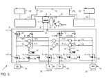
- Fig. 3 is a schematic block diagram of a brake system 1 shown in a third embodiment.
- This in Fig. 3 shown brake system 1 is hereby largely the same in Fig. 1 constructed brake system 1 constructed.
- the brake system 1 comprises the in Fig. 3 Brake system 1 shown a passive vacuum brake booster 23.
- the brake system 1 comprises a first slip control system with a first servo motor M1, which simultaneously pumps pumps P11, P12 of the first slip control system.
- the first servo motor M1 is here a speed-controlled servomotor M1.
- the first slip control system is in this case associated with the first brake circuit, wherein the first servomotor M1 is supplied by the first battery 18 with electrical energy.
- eight of the Fig. 3 shown twelve electromechanical valves 11, which act as ABS valves associated with the first brake circuit.
- the eight ABS valves are identified by the reference numeral 11a.
- the speed sensors 15 are assigned to the first brake circuit.
- the brake system 1 comprises a second slip control system with a second servomotor M2 and pumps P21, P22 of the second slip control system.
- the second servomotor M2 is in this case associated with the second brake circuit and is supplied from the second battery 20 with electrical energy.
- the second brake circuit comprises electric parking brakes 22, which are assigned to the rear wheels HR, HL.
- the first control and evaluation device 17 controls the first servomotor M1 and the ABS valves 11a.
- the second control and evaluation device 19 controls the second servo motor M2 and the electric parking brakes 22, which are each assigned to a rear wheel HL, HR.
- a brake light switch 24 and the part 11B as ESP separation valves are partially redundant.
- the pressure sensor 13 may be partially redundant, but this is not shown.
- the pressure sensor 13 and the brake light switch 24 each have two output channels, wherein an output channel to the first control and evaluation device 17 and the second output channel to the second control and evaluation device 19 is connected.
- the ESP isolation valves 11 b have two input channels, wherein a first input channel to the first control and evaluation device 17 and a second input channel to the second control and evaluation device 19 is connected.
- the ESP isolation valves 11 b can be controlled both by the first control and evaluation device 17 and by the second control and evaluation device 19, wherein the control signals of the first control and evaluation device 17 have priority over a priority circuit.
- the comments to Fig. 2 are the rear wheels associated electromechanical valves 11 normally closed valves.
- these electromechanical valves 11 are energized during braking.
- the servomotors M1, M2 and the pumps P11, P12, P21, P22 can in this case be designed such that the slip control systems formed by them can each generate a desired service braking effect and, for example, can build up a maximum brake pressure of, for example, 200 bar.
- the two slip control systems can work in parallel, whereby a high dynamics of pressure changes is made possible.
- the first brake circuit can be the one in the notes to Fig. 1 have described single error.
- a determination of a desired braking effect as a function of an output signal transmitted through the second output channel of the pressure sensor 13 to the second control and evaluation device 19 and depending on the output signal transmitted through the second output channel of the brake light switch 24 to the second control and evaluation device 19 respectively.
- a pressure build-up by the second servomotor M2 can take place. Since the first brake circuit is deactivated in this case, the electromechanical valves 11 associated with the rear wheels are de-energized and thus enter a closed state. Therefore, the rear wheels HL, HR as in relation to Fig. 2 described no longer be hydraulically braked. The deceleration of the rear wheels HL, HR is now via the electric parking brakes 22, which are assigned to the second brake circuit. How to Fig. 2 described, a predetermined braking force distribution can also be set here.
- a determination of a desired braking effect can be determined in accordance with the output signals transmitted through the first output channels of the pressure sensor 13 and the brake light switch 24 to the first control and evaluation device 17.
- a pressure build-up can now be done by the first servo motor M1. Since the wheel speed sensors 15 are assigned to the first brake circuit, a slip control is available in this case.
Landscapes
- Engineering & Computer Science (AREA)
- Transportation (AREA)
- Mechanical Engineering (AREA)
- Regulating Braking Force (AREA)
- Valves And Accessory Devices For Braking Systems (AREA)
Abstract
Description
Die Erfindung betrifft ein Bremssystem eines Fahrzeugs, insbesondere eines teil-, hoch- oder vollautomatisch fahrbaren Fahrzeugs, sowie ein Verfahren zur Erzeugung einer Bremskraft in dem Fahrzeug.The invention relates to a braking system of a vehicle, in particular a partially, highly or fully automatically movable vehicle, and a method for generating a braking force in the vehicle.
Die
Die
Die
Die
Bei der Auslegung von bekannten Bremssystem, z.B. den vorhergehend erläuterten Bremssystemen des Standes der Technik, wird davon ausgegangen, dass ein Fahrzeugführer bei einem Einfachfehler im Bremssystem ohne oder mit nur geringer Verzögerung eine Fahrzeugführung übernehmen kann. Der Fahrzeugführer kann im Falle eines Fehlers im Bremssystem z.B. durch Betätigung eines Bremspedals eine Bremskraft erzeugen. Somit kann eine Hilfsbremswirkung, die das Bremssystem im Fehlerfall bereitstellen muss, geringer als eine Betriebsbremswirkung sein, die im fehlerfreien Zustand des Bremssystems bereitgestellt werden kann.In the design of known brake system, e.g. the previously discussed braking systems of the prior art, it is assumed that a driver can take over a vehicle management with a single error in the brake system with little or no delay. The driver may, in the event of a fault in the braking system e.g. generate a braking force by pressing a brake pedal. Thus, an auxiliary braking effect, which the braking system must provide in the event of a fault, can be less than a service braking effect that can be provided in the fault-free state of the braking system.
Der Bereich des automatischen Fahrens rückt immer stärker in den Fokus der Automobilentwicklung. Beim automatischen Fahren ist ein Fahrzeugführer zwar körperlich vorhanden, er kann jedoch abgelenkt sein. Ist ein Fahrzeugführer abgelenkt, so kann er nur mit einer unerwünschten Verzögerung eine Steuerung, insbesondere ein Bremsen des Fahrzeuges, übernehmen.The field of automatic driving is increasingly becoming the focus of automotive development. While a driver is physically present in automatic driving, he may be distracted. If a vehicle driver is distracted, he can only take over control, in particular braking of the vehicle, with an undesirable delay.
Es stellt sich daher das technische Problem, ein Bremssystem eines Fahrzeugs, insbesondere eines teil-, hoch- oder vollautomatischen betreibbaren Fahrzeugs, und ein Verfahren zur Erzeugung einer Bremskraft in einem solchen Fahrzeug zu schaffen, welche auch im Fehlerfall, insbesondere im Fall eines Einfachfehlers, eine sichere Betriebsweise des Fahrzeuges ermöglichen, insbesondere wenn ein Fahrzeugführer verzögert eine Fahrzeugführung übernimmt.The technical problem therefore arises of providing a brake system of a vehicle, in particular of a partially, fully or fully automatic operable vehicle, and a method for generating a braking force in such a vehicle, which also in the event of a fault, in particular in the case of a single fault, enable safe operation of the vehicle, especially when a vehicle driver takes over a delayed vehicle guidance.
Die Lösung des technischen Problems ergibt sich durch die Gegenstände mit den Merkmalen der Ansprüche 1 und 10. Weitere vorteilhafte Ausgestaltungen der Erfindung ergeben sich aus den Unteransprüchen.The solution of the technical problem results from the objects with the features of
Vorgeschlagen wird ein Bremssystem eines Fahrzeugs, insbesondere eines teil-, hoch- oder vollautomatisch betreibbaren Fahrzeugs.Proposed is a braking system of a vehicle, in particular a partially, highly or fully automatically operable vehicle.
Ein hochautomatisch betreibbares Fahrzeug bezeichnet hierbei ein Fahrzeug, bei dem eine Fahrzeugführung automatisch, also ohne Eingriff eines Fahrzeugführers, erfolgen kann. Der Fahrer ist körperlich anwesend, aber abgelenkt (z.B. liest er ein Buch). Er kann somit erst nach einiger Zeit die Fahraufgabe wieder selbst übernehmen. Hierbei kann z.B. ein Lenken und/oder ein Antreiben und/oder ein Bremsen des Fahrzeugs zeitweise automatisch erfolgen. Hierfür kann das Fahrzeug entsprechende Systeme, z.B. ein automatisches Lenksystem, ein automatisches Antriebssystem und ein automatisches Bremssystem, umfassen.In this case, a vehicle which can be operated in a highly automatic manner designates a vehicle in which a vehicle guidance can take place automatically, that is to say without the intervention of a vehicle driver. The driver is physically present but distracted (for example, he is reading a book). He can thus take over the driving task again after some time. Here, e.g. steering and / or driving and / or braking of the vehicle take place at times automatically. For this, the vehicle may have corresponding systems, e.g. an automatic steering system, an automatic drive system and an automatic braking system.
Die Bezeichnung teilautomatisch, hochautomatisch oder vollautomatisch beschreiben unterschiedliche Automatisierungsgrade einer Fahrzeugführung. Neben diesen Automatisierungsgraden können z.B. noch die Automatisierungsgrade "Driver only" und "Assistiert" existieren. In einem hochautomatisch betriebenen Fahrzeug kann z.B. eine Quer-und Längsführung des Fahrzeugs durch ein Automatisierungssystem des Fahrzeugs erfolgen, wobei ein Fahrzeugführer das Automatisierungssystem und die Fahrzeugführung nicht dauerhaft überwachen muss. Bei einem vollautomatisch betriebenen Fahrzeug übernimmt das Automatisierungssystem beispielsweise eine Quer- und Längsführung vollständig in einem definierten Anwendungsfall. Hierbei muss der Fahrzeugführer das Automatisierungssystem und die Fahrzeugführung nicht mehr überwachen. Bei einem "Driver only"-betriebenen Fahrzeug führt der Fahrzeugführer dauerhaft die Längs- und Querführung aus. Bei einem assistiertbetriebenen Fahrzeug führt der Fahrzeugführer dauerhaft entweder die Quer- oder die Längsführung aus. Die jeweils andere Fahraufgabe wird in gewissen Grenzen von dem Automatisierungssystem ausgeführt, wobei der Fahrzeugführer das Automatisierungssystem und die Fahrzeugführung dauerhaft überwachen muss. In einem teilautomatisiert-betriebenen Fahrzeug kann das Automatisierungssystem die Quer- und Längsführung übernehmen, wobei der Fahrzeugführer das Automatisierungssystem und die Fahrzeugführung dauerhaft überwachen muss.The term semi-automatic, highly automatic or fully automatic describe different degrees of automation of a vehicle guidance. Besides these degrees of automation, e.g. even the automation levels "Driver only" and "Assisted" exist. In a highly automated vehicle, e.g. a transverse and longitudinal guidance of the vehicle by an automation system of the vehicle carried, wherein a driver does not need to monitor the automation system and the vehicle management permanently. For example, in a fully automatic vehicle, the automation system takes over a lateral and longitudinal guidance completely in a defined application. In this case, the driver no longer has to monitor the automation system and the vehicle guidance. In a "driver only" powered vehicle, the driver permanently performs the longitudinal and transverse guidance. In an assist-operated vehicle, the driver permanently performs either the lateral or longitudinal guidance. The respective other driving task is carried out within certain limits of the automation system, the driver must monitor the automation system and the vehicle management permanently. In a partially automated-operated vehicle, the automation system can take over the lateral and longitudinal guidance, whereby the driver must permanently monitor the automation system and the vehicle management.
Bei einem vollautomatischen Fahrzeug kann der Fahrzeugführer körperlich anwesend, jedoch geistig abwesend sein, beispielsweise weil er abgelenkt ist. Somit kann nicht sichergestellt sein, dass der Fahrzeugführer die Fahrzeugführung im Bedarfsfall sofort oder möglichst rasch wieder übernehmen kann. Der Fahrzeugführer kann hierdurch als mögliche Rückfallebene bei Auftreten eines Fehlers ausfallen. Dies erfordert in der Konsequenz erhöhte Redundanzen.In a fully automatic vehicle, the driver may be physically present but mentally absent, for example, because he is distracted. Thus, it can not be ensured that the driver can take over the vehicle guidance if necessary immediately or as quickly as possible. The driver can thereby fail as a possible fallback when an error occurs. As a consequence, this requires increased redundancies.
Das vorgeschlagene Bremssystem umfasst einen ersten Bremskreis und mindestens einen weiteren Bremskreis. Der erste Bremskreis umfasst eine erste Druckerzeugungseinrichtung und der mindestens eine weitere Bremskreis umfasst eine weitere Druckerzeugungseinrichtung. Eine Druckerzeugungseinrichtung kann beispielsweise als Pumpe ausgebildet sein oder eine Pumpe umfassen. Die Druckerzeugungseinrichtung dient zum Erzeugen eines Druckes, wodurch wiederum eine Bremswirkung erzeugt wird.The proposed brake system comprises a first brake circuit and at least one further brake circuit. The first brake circuit comprises a first pressure generating device and the at least one further brake circuit comprises a further pressure generating device. A pressure generating device may be designed, for example, as a pump or comprise a pump. The pressure generating device serves to generate a pressure, which in turn generates a braking effect.
Das Bremssystem ist ein hydraulisches Bremssystem, welches ein Betriebsmittel bzw. -fluid und geeignete Fluidkanäle umfasst, die die Druckerzeugungseinrichtungen mit Radbremszylindern, die jeweils ein drehbares Rad des Fahrzeugs bremsen können, fluidtechnisch verbinden. Weiter kann das Bremssystem Ventile, beispielsweise stromgesteuerte elektromechanische Ventile zur Steuerung eines Fluidstromes im Bremssystem sowie zu einer Druckverteilungssteuerung umfassen. Weiter kann das Bremssystem Niederdruckspeicher zur Aufnahme des Betriebsmittels umfassen.The brake system is a hydraulic brake system that includes a fluid and suitable fluid channels that fluidly connect the pressure generating devices to wheel brake cylinders, each of which can brake a rotatable wheel of the vehicle. Further, the brake system may include valves, such as current-controlled electro-mechanical valves for controlling fluid flow in the brake system, as well as pressure distribution control. Further, the brake system may include low pressure accumulator for receiving the resource.
Das Bremssystem umfasst eine erste Energiequelle und mindestens eine weitere Energiequelle. Die Energiequelle kann beispielsweise als Batterie, als Kondensator oder als ein anderer Energiespeicher ausgebildet sein. Hierbei kann die erste Energiequelle eine Ausgangsspannung aufweisen, die von einer Ausgangsspannung der weiteren Energiequelle verschieden ist. Beispielsweise kann die erste Energiequelle eine Ausgangsspannung von 48 V (Gleichspannung) und die weitere Energiequelle eine Ausgangsspannung von 12 V (Gleichspannung) aufweisen.The braking system comprises a first energy source and at least one further energy source. The energy source can be designed, for example, as a battery, as a capacitor or as another energy store. In this case, the first energy source may have an output voltage which is different from an output voltage of the further energy source. By way of example, the first energy source may have an output voltage of 48 V (DC voltage) and the further energy source an output voltage of 12 V (DC voltage).
Weiter ist die erste Druckerzeugungseinrichtung aus der ersten Energiequelle mit Energie versorgbar. Hierbei kann die erste Druckerzeugungseinrichtung ausschließlich aus der ersten Energiequelle versorgbar sein. Versorgbar bedeutet hierbei, dass beim Betrieb der ersten Druckerzeugungseinrichtung Energie, beispielsweise ausschließlich, aus der ersten Energiequelle entnommen wird. Die weitere Druckerzeugungseinrichtung ist aus der weiteren Energiequelle versorgbar, beispielsweise ausschließlich versorgbar. Hierbei kann das Bremssystem derart ausgebildet sein, dass ein Energiefluss aus der ersten Energiequelle in die zweite Energiequelle oder umgekehrt ausgeschlossen ist.Furthermore, the first pressure generating device can be supplied with energy from the first energy source. In this case, the first pressure-generating device can be supplied exclusively from the first energy source. In this case, supplying means that, during operation of the first pressure generating device, energy, for example exclusively, is taken from the first energy source. The further pressure-generating device can be supplied from the further energy source, for example exclusively supplied. In this case, the brake system may be designed such that an energy flow from the first energy source into the second energy source or vice versa is excluded.
Weiter ist in dem Bremssystem ein Einfachfehler in dem ersten oder dem weiteren Bremskreis detektierbar. Hierfür kann das Bremssystem beispielsweise eine Steuer- und Auswerteeinrichtung umfassen, mittels derer ein Einfachfehler detektierbar ist. Ein Einfachfehler bedeutet hierbei, dass entweder eine Funktionsfähigkeit des ersten Bremskreises, z.B. um ein vorbestimmtes Maß, beeinträchtigt oder nicht mehr gegeben ist oder eine Funktionsfähigkeit des weiteren Bremskreises, z.B. um ein vorbestimmtes Maß, beeinträchtigt oder nicht mehr gegeben ist. Bei einem Einfachfehler liegt also entweder im ersten Bremskreis eine Fehlfunktion, z.B. eine Fehlfunktion mindestens eines dem ersten Bremskreis zugeordneten Elements, oder eine Fehlfunktion im weiteren Bremskreis, z.B. eine Fehlfunktion eines dem weiteren Bremskreis zugeordneten Elements, vor. Beim Vorliegen eines solchen Einfachfehlers kann der entsprechende Bremskreis eine gewünschte, beispielsweise maximale, Bremswirkung nicht mehr erzeugen. Der Fehler kann an beliebiger Stelle eines Bremskreises oder in der dem Bremskreis zugeordneten Energieversorgung liegen.Furthermore, a single fault in the first or the further brake circuit can be detected in the brake system. For this purpose, the brake system may comprise, for example, a control and evaluation device by means of which a single fault can be detected. A simple error here means that either a functionality of the first brake circuit, for example by a predetermined amount, impaired or no longer exists or a functionality of the other brake circuit, for example by a predetermined amount, impaired or not given is. In the case of a single fault, a malfunction, eg a malfunction of at least one element assigned to the first brake circuit, or a malfunction in the further brake circuit, eg a malfunction of an element associated with the further brake circuit, is thus present either in the first brake circuit. In the presence of such a single error, the corresponding brake circuit can no longer produce a desired, for example maximum, braking effect. The fault may be at any point in a brake circuit or in the power supply associated with the brake circuit.
Weiter ist, z.B. mittels der vorhergehend erwähnten Steuer- und Auswerteeinrichtung, ein fehlerhafter Bremskreis deaktivierbar und ein funktionsfähiger Bremskreis aktivierbar. In einem Normalbetrieb kann beispielsweise der erste Bremskreis betrieben werden, um das Fahrzeug zu bremsen. Hierbei ist der weitere Bremskreis inaktiv. Es ist jedoch auch möglich, dass im Normalbetrieb der weitere Bremskreis betrieben wird, wobei der erste Bremskreis inaktiv ist. Das Bremssystem ist derart ausgebildet, dass von einem fehlerhaften Bremskreis auf einen funktionsfähigen Bremskreis umgeschaltet werden kann.Further, e.g. by means of the aforementioned control and evaluation, a faulty brake circuit can be deactivated and activated a functional brake circuit. In a normal operation, for example, the first brake circuit can be operated to brake the vehicle. In this case, the further brake circuit is inactive. However, it is also possible that the further brake circuit is operated in normal operation, wherein the first brake circuit is inactive. The brake system is designed such that it can be switched from a faulty brake circuit to a functional brake circuit.
Erfindungsgemäß ist eine mittels der ersten Druckerzeugungseinrichtung bzw. mittels des ersten Bremskreises erzeugbare Bremswirkung größer als eine oder gleich einer vorbestimmten Betriebsbremswirkung. Beispielsweise kann eine mittels der ersten Druckerzeugungseinrichtung bzw. mittels des ersten Bremskreises erzeugbare maximale Bremswirkung größer als eine oder gleich einer vorbestimmten Betriebsbremswirkung sein. Eine Betriebsbremswirkung kann beispielsweise gemäß der Regelung ECE-R13H als eine vorbestimmte Bremsbeschleunigung, beispielsweise mindestens 6,43 m/s2, bei einer vorbestimmten Pedalkraft, beispielsweise maximal 500 N Pedalkraft, definiert sein, wobei eine Schwelldauer einen vorbestimmten Schwellwert, beispielsweise 600 ms, nicht überschreiten darf. Eine Pedalkraft bezeichnet hierbei eine Kraft, die ein Fahrzeugführer auf ein Bremspedal des Bremssystems aufbringt. Eine Schwelldauer bezeichnet hierbei eine Zeitdauer von einem Beginn einer Betätigung des Bremspedals bis zum Erreichen der vorhergehend erläuterten Bremsbeschleunigung.According to the invention, a braking effect which can be generated by means of the first pressure generating device or by means of the first brake circuit is greater than or equal to a predetermined service braking effect. For example, a maximum braking effect which can be generated by means of the first pressure-generating device or by means of the first brake circuit can be greater than or equal to a predetermined service-braking effect. A service brake effect may be defined, for example, according to regulation ECE-R13H as a predetermined deceleration acceleration, for example at least 6.43 m / s 2 , at a predetermined pedal force, for example a maximum of 500 N pedal force, wherein a threshold duration is a predetermined threshold, for example 600 ms, must not exceed. A pedal force here refers to a force that applies a driver to a brake pedal of the brake system. A threshold duration in this case denotes a period of time from the beginning of an actuation of the brake pedal until reaching the previously explained braking acceleration.
Weiter ist eine mittels der weiteren Druckerzeugungseinrichtung bzw. mittels des weiteren Bremskreises erzeugbare Bremswirkung, beispielsweise erzeugbare maximale Bremswirkung, größer als die oder gleich der vorbestimmten Betriebsbremswirkung. Somit können sowohl der erste Bremskreis als auch der weitere Bremskreis jeweils eine Bremswirkung erzeugen, die größer als die oder gleich der gewünschten Betriebsbremswirkung ist. Dies unterscheidet das vorgeschlagene Bremssystem von konventionellen Bremssystemen, bei denen im Falle eines Einfachfehlers das Bremssystem nur eine Hilfsbremswirkung erzeugt werden kann, die kleiner als die erläuterte Betriebsbremswirkung ist. Bei konventionellen Bremssystemen wird davon ausgegangen, dass ein Fahrzeugführer nach Eintritt eines Einfachfehlers eine Fahrzeugführung sofort oder mit einer minimalen Verzögerung übernimmt und, zusätzlich zur Hilfsbremswirkung, eine weitere Bremswirkung, z.B. eine Muskelkraftbremswirkung, beispielsweise durch Betätigung des Bremspedals, erzeugt.Furthermore, a braking effect that can be generated by means of the further pressure-generating device or by means of the further brake circuit, for example, the maximum braking action that can be generated, is greater than or equal to the predetermined service braking effect. Thus, both the first brake circuit and the further brake circuit can each generate a braking effect which is greater than or equal to the desired service braking effect. This distinguishes the proposed braking system from conventional braking systems in which, in the case of a single fault, the braking system can only produce an auxiliary braking action that is less than the illustrated service braking effect. With conventional brake systems will of it assumed that a driver after the occurrence of a single fault takes over a vehicle control immediately or with a minimum delay and, in addition to the auxiliary braking effect, another braking effect, eg a muscle power braking effect, for example by pressing the brake pedal generated.
Beim zumindest teilweise automatischen Betrieb des Fahrzeugs ist der Fahrzeugführer zwar körperlich vorhanden, jedoch kann er derart abgelenkt sein, dass er bei Eintritt eines Einfachfehlers die Fahrzeugführung nicht sofort, beispielsweise erst nach einer vorbestimmten Zeitdauer, beispielsweise nach 30 s, übernimmt. In diesem Fall ist es wünschenswert, dass ein Bremssystem beim Eintritt eines Einfachfehlers weiterhin in der Lage ist, mindestens die gewünschte Betriebsbremswirkung zu erzeugen und nicht nur eine Hilfsbremswirkung.In the case of at least partially automatic operation of the vehicle, although the driver is physically present, he may be so distracted that he does not take over the vehicle guidance immediately, for example after a predetermined period of time, for example after 30 seconds, if a single fault occurs. In this case, it is desirable that a brake system continue to be capable of producing at least the desired service braking effect upon occurrence of a single fault rather than just an auxiliary braking action.
Das vorgeschlagene Bremssystem, in welchem der erste Bremskreis und der weitere Bremskreis jeweils mindestens die Betriebsbremswirkung erzeugen können, ermöglicht in vorteilhafter Weise, dass auch bei Eintritt eines Einfachfehlers in einem der Bremskreise immer noch die Betriebsbremswirkung erreicht werden kann. Somit erfolgt keine Verringerung der erzeugbaren Bremswirkung. Hierdurch kann in vorteilhafter Weise eine gewünschte Betriebsbremswirkung auch gewährleistet werden, nachdem ein Einfachfehler in einem der Bremskreise aufgetreten ist, ein Fahrzeugführer die Fahrzeugführung jedoch noch nicht übernommen hat. Somit ermöglicht das vorgeschlagene Bremssystem, dass bei einem intakten Bremssystem mindestens die Betriebsbremswirkung erzeugt werden kann. Bei einem Einfachfehler kann ebenfalls mindestens die Betriebsbremswirkung erzeugt werden. In diesem Fall kann auch eine z.B. akustische und/oder optische und/oder haptische Warnung eines Fahrzeugführers sowie eine Aufforderung zur Übernahme der Fahrzeugführung erfolgen. Bei einem Doppelfehler, also bei einer Fehlfunktion sowohl des ersten als auch des weiteren Bremskreises kann mindestens eine Hilfsbremswirkung erzeugt werden. Auch in diesem Fall kann eine Warnung des Fahrzeugführers und eine dringende Aufforderung zur Übernahme erfolgen.The proposed brake system, in which the first brake circuit and the further brake circuit can each generate at least the service brake effect, advantageously makes it possible to still achieve the service brake effect even if a single fault occurs in one of the brake circuits. Thus, there is no reduction in the producible braking effect. As a result, a desired service braking effect can also be ensured in an advantageous manner after a single fault has occurred in one of the brake circuits, but a driver has not yet taken over the vehicle guidance. Thus, the proposed brake system allows at least the service braking effect can be generated in an intact brake system. In the case of a single fault, at least the service braking effect can also be generated. In this case also a e.g. acoustic and / or visual and / or haptic warning of a driver and a request to take over the vehicle management done. In the case of a double fault, ie in the case of a malfunction of both the first and the further brake circuit, at least one auxiliary braking effect can be generated. Also in this case, a warning of the driver and an urgent request to take over.
Das vorgeschlagene Bremssystem ist somit auch im Einfachfehlerfall betriebsbereit ("failoperational").The proposed brake system is thus ready for operation even in the case of a single fault ("failoperational").
Das vorgeschlagene Bremssystem kann weiter in zwei Betriebsarten betrieben werden. In einer ersten Betriebsart wird die Fahrzeugführung vom Fahrzeugführer ausgeführt. Hierbei kann das Bremssystem als so genannte Hilfskraftbremse arbeiten, wobei eine Bremswirkung, z.B. ein Bremsdruck, aus einer Muskelkraft des Fahrzeugführers und einer Kraft eines Bremskraftverstärkers erzeugt wird. In einer weiteren Betriebsart wird eine Fahrzeugführung automatisch durchgeführt (automatisches Fahren). Hierbei arbeitet das Bremssystems als so genannte Fremdkraftbremse, wobei eine Bremswirkung, z.B. ein Bremsdruck, ausschließlich aus einer Maschinenkraft erzeugt wird.The proposed brake system can be further operated in two modes. In a first mode, the vehicle guidance is performed by the driver. Here, the brake system may operate as a so-called auxiliary brake, wherein a braking effect, such as a brake pressure, is generated from a muscle power of the driver and a force of a brake booster. In another mode, vehicle guidance is automatically performed (automatic driving). Here, the brake system works as so said power brake, wherein a braking effect, such as a brake pressure, is generated exclusively from a machine power.
In einer weiteren Ausführungsform umfasst der erste Bremskreis weiterhin eine erste Auswerte- und Steuereinrichtung und mindestens einen dem ersten Bremskreis zugeordneten Sensor. Ein dem Bremskreis zugeordneter Sensor bezeichnet hierbei einen Sensor oder eine Erfassungseinrichtung, deren Ausgangssignal zur Steuerung oder Regelung einer von dem ersten Bremskreis erzeugten Bremswirkung genutzt wird. Hierbei kann die erste Auswerte- und Steuereinrichtung als entsprechende Steuer- oder Regeleinrichtung ausgebildet sein. Insbesondere kann die erste Auswerte- und Steuereinrichtung daten- oder signaltechnisch mit dem dem ersten Bremskreis zugeordneten Sensor verbunden sein. Selbstverständlich kann der erste Bremskreis auch weitere dem ersten Bremskreis zugeordnete Sensoren umfassen. Auch kann der erste Bremskreis einen Sensor oder mehrere Sensoren umfassen, der/die ausschließlich dem ersten Bremskreis zugeordnet ist/sind. Hierbei wird das Ausgangssignal des Sensors ausschließlich zur Steuerung oder Regelung der vom ersten Bremskreis erzeugten Bremswirkung und somit nicht zur Steuerung bzw. Regelung z.B. der vom weiteren Bremskreis erzeugten Bremswirkung genutzt.In a further embodiment, the first brake circuit further comprises a first evaluation and control device and at least one sensor associated with the first brake circuit. A sensor assigned to the brake circuit here denotes a sensor or a detection device whose output signal is used to control or regulate a braking effect generated by the first brake circuit. In this case, the first evaluation and control device can be designed as a corresponding control or regulating device. In particular, the first evaluation and control device can be connected to the sensor associated with the first brake circuit in terms of data or signaling. Of course, the first brake circuit may also include further sensors associated with the first brake circuit. Also, the first brake circuit may comprise a sensor or a plurality of sensors, which is / are exclusively associated with the first brake circuit. In this case, the output signal of the sensor is used exclusively for controlling or regulating the braking effect generated by the first brake circuit and thus not for controlling, e.g. used the braking effect generated by the further brake circuit.
Weiter umfasst der mindestens eine weitere Bremskreis weiterhin eine weitere Auswerte- und Steuereinrichtung und mindestens einen dem weiteren Bremskreis, z.B. ausschließlich, zugeordneten Sensor.Furthermore, the at least one further brake circuit further comprises a further evaluation and control device and at least one further brake circuit, e.g. exclusively, assigned sensor.
Mittels der ersten Auswerte- und Steuereinrichtung ist eine Erzeugung der Bremswirkung abhängig von einem Ausgangssignal des mindestens einen dem ersten Bremskreis zugeordneten Sensors und unabhängig von einem Ausgangssignal des mindestens einen dem weiteren Bremskreis zugeordneten Sensors steuerbar. Somit wird/werden also das Ausgangssignal/die Ausgangssignale des/der dem weiteren Bremskreis zugeordneten Sensors/Sensoren nicht zur Steuerung bzw. Regelung der Bremswirkung des ersten Bremskreises verwendet.By means of the first evaluation and control device, generation of the braking effect is controllable as a function of an output signal of the at least one sensor assigned to the first brake circuit and independently of an output signal of the at least one sensor assigned to the further brake circuit. Thus, the output signal (s) of the sensor (s) associated with the further brake circuit will not be used to control or regulate the braking action of the first brake circuit.
Entsprechend ist mittels der weiteren Auswerte- und Steuereinrichtung eine Erzeugung der Bremswirkung abhängig von einem Ausgangssignal des mindestens einen dem weiteren Bremskreis zugeordneten Sensors und unabhängig von einem Ausgangssignal des mindestens einen dem ersten Bremskreis zugeordneten Sensors steuerbar.Accordingly, by means of the further evaluation and control device, generation of the braking effect can be controlled as a function of an output signal of the at least one sensor associated with the further brake circuit and independently of an output signal of the at least one sensor assigned to the first brake circuit.
Die erste Steuer- und Auswerteeinrichtung und der mindestens eine dem ersten Bremskreis zugeordnete Sensor ist hierbei aus der ersten Energiequelle versorgbar. Die weitere Steuer- und Auswerteeinrichtung und der mindestens eine dem weiteren Bremskreis zugeordnete Sensor ist aus der weiteren Energiequelle versorgbar. Hierbei kann die Energieversorgung des ersten Bremskreises, beispielsweise ein zur Energieversorgung des ersten Bremskreises dienender erster Stromkreis, energietechnisch oder elektrisch getrennt von der Energieversorgung des weiteren Bremskreises, beispielsweise von einem zur Energieversorgung des weiteren Bremskreises dienenden weiteren Stromkreis, ausgebildet sein. Hierdurch wird verhindert, dass elektrische Energie vom ersten Bremskreis in den weiteren Bremskreis und umgekehrt fließt.The first control and evaluation device and the at least one sensor associated with the first brake circuit can be supplied from the first energy source. The further control and evaluation device and the at least one associated with the further brake circuit Sensor can be supplied from the further energy source. In this case, the energy supply of the first brake circuit, for example, a power supply for the first brake circuit serving first circuit, energy-technically or electrically separated from the power supply of the further brake circuit, for example, from an energy supply to the further brake circuit serving further circuit may be formed. This prevents electrical energy from flowing from the first brake circuit into the further brake circuit and vice versa.
Weiter können die erste und die weitere Auswerte- und Steuereinrichtung signal- oder datentechnisch verbunden sein.Furthermore, the first and the further evaluation and control device can be connected by signal or data technology.
Hierdurch ergibt sich in vorteilhafter Weise ein Bremssystem, welches auch in Bezug auf eine Energieversorgung aller den einzelnen Bremskreisen zugeordneten Elemente mehrkreisig, beispielsweise zweikreisig, ausgebildet ist. Dies ermöglicht ein einfach zu betreibendes Bremssystem, da beispielsweise ein mit Energie versorgter, dem ersten Bremskreis zugeordneter Sensor bei einer energetisch unversorgten ersten Steuer- und Auswerteeinrichtung keine sinnvolle technische Funktion mehr ausüben kann.This results in an advantageous manner, a brake system, which is also in relation to a power supply of all the individual brake circuits associated elements mehrkreisig, for example, zweikreisig formed. This allows an easy-to-operate braking system, since, for example, an energy-supplied, the first brake circuit associated sensor in an energetically unprovoked first control and evaluation no meaningful technical function can exercise more.
Ein Datenaustausch zwischen den Auswerte- und Steuereinrichtungen, z.B. über einen Datenbus, z.B. einen CAN-Bus oder Flexray-Bus, kann hierbei sinnvoll zur Detektion eines Einfachfehlers in dem jeweils anderen Bremskreis als auch zu einer gegenseitigen Überwachung sein.A data exchange between the evaluation and control devices, e.g. via a data bus, e.g. a CAN bus or Flexray bus, this can be useful for the detection of a single error in the other brake circuit as well as to a mutual monitoring.
Hierbei bezeichnen Elemente, die einem Bremskreis zugeordnet sind, Elemente, die zur Steuerung bzw. Regelung der von dem entsprechenden Bremskreis erzeugten Bremswirkung notwendig, jedoch zur Steuerung bzw. Regelung der Bremswirkung des weiteren Bremskreises nicht notwendig sind. Entsprechend können Elemente vorgesehen sein, die mehreren Bremskreisen zugeordnet sind. Diese Elemente bezeichnen Elemente, die zur Erzeugung der Bremswirkungen in einigen oder mehreren Bremskreise notwendig sind. Beispielsweise können Sensoren vorgesehen sein, deren Ausgangssignale sowohl zur Steuerung bzw. Regelung der Bremswirkung des ersten Bremskreises als auch des weiteren Bremskreises genutzt werden. Derartige Elemente, beispielsweise Sensoren, können derart ausgebildet sein, dass sie in einem gemeinsamen Gehäuse zwei Sensorelemente aufweisen, von denen ein erstes Sensorelement von der ersten Energiequelle und das zweite Sensorelement von der zweiten Energiequelle mit elektrischer Energie versorgt wird. Weiterhin kann das erste Sensorelement mit der ersten Steuer- und Auswerteeinrichtung des ersten Bremskreises und das zweite Sensorelement mit der weiteren Steuer- und Auswerteeinrichtung des weiteren Bremskreises daten- oder signaltechnisch verbunden sein.In this case, elements which are assigned to a brake circuit designate elements which are necessary for the control or regulation of the braking effect generated by the corresponding brake circuit, but are not necessary for controlling or regulating the braking action of the further brake circuit. Accordingly, elements may be provided which are assigned to a plurality of brake circuits. These elements designate elements necessary to produce the braking effects in some or more brake circuits. For example, sensors may be provided, whose output signals are used both for controlling or regulating the braking effect of the first brake circuit and the further brake circuit. Such elements, for example sensors, can be configured such that they have two sensor elements in a common housing, of which a first sensor element is supplied with electrical energy by the first energy source and the second sensor element by the second energy source. Furthermore, the first sensor element with the first control and evaluation of the first brake circuit and the second sensor element with the further control and evaluation of the further brake circuit be connected by data or signal technology.
In einer weiteren Ausführungsform ist die erste Druckerzeugungseinrichtung als aktiver Bremskraftverstärker ausgebildet. Ein aktiver Bremskraftverstärker kann z.B. als aktiver Vakuum-Bremskraftverstärker ausgebildet sein, wobei eine Bremskraft in Abhängigkeit einer Druckdifferenz eines Vakuums zu einem Umgebungsdruck erzeugt wird. Alternativ kann der aktive Bremskraftverstärker als hydraulischer Bremskraftverstärker ausgebildet sein, wobei eine Krafterzeugung mittels eines geeigneten hydraulischen Betriebsmittels, z.B. Betriebsfluids, erzeugt wird. Bevorzugt kann ein aktiver Bremskraftverstärker als elektromechanischer Bremskraftverstärker ausgebildet sein, wobei eine Krafterzeugung z.B. durch einen Elektromotor, beispielsweise ein Servomotor, und ein entsprechendes Getriebe, beispielsweise ein rotatorisch-translatorisches Getriebe, erzeugt wird. Weiter alternativ kann der aktive Bremskraftverstärker auch als hydraulisches oder elektromechanisches Brake-by-Wire-System ausgebildet sein.In a further embodiment, the first pressure generating device is designed as an active brake booster. An active brake booster can e.g. be formed as an active vacuum brake booster, wherein a braking force in response to a pressure difference of a vacuum is generated to an ambient pressure. Alternatively, the active brake booster can be designed as a hydraulic brake booster, wherein a force generation by means of a suitable hydraulic operating means, e.g. Operating fluid is generated. Preferably, an active brake booster can be designed as an electromechanical brake booster, wherein a force generation, e.g. by an electric motor, for example a servomotor, and a corresponding gear, for example a rotary translatory gear is generated. Further alternatively, the active brake booster can also be designed as a hydraulic or electromechanical brake-by-wire system.
Weiter kann die erste Druckerzeugungseinrichtung alternativ als Pumpeinrichtung oder Pumpe eines ersten Schlupfregelsystems ausgebildet sein oder diese umfassen. In diesem Fall kann die erste Druckerzeugungseinrichtung auch einen Motor zum Antrieb der Pumpeinrichtung umfassen. Bevorzugt kann die Drehzahl des Motors regelbar sein. Hierbei bezeichnet eine Pumpeinrichtung eine Druckerzeugungseinrichtung, die neben dem Motor je Bremskreis einen oder mehrere Pumpenelemente haben kann. Ein Schlupfregelsystem kann auch als Antiblockiersystem (ABS) dienen.Furthermore, the first pressure-generating device may alternatively be designed as or comprise a pump device or pump of a first slip control system. In this case, the first pressure generating device may also include a motor for driving the pumping device. Preferably, the speed of the motor can be regulated. Here, a pump means a pressure generating device, which may have one or more pump elements in addition to the engine per brake circuit. A slip control system can also serve as an anti-lock braking system (ABS).
Hierdurch ergibt sich in vorteilhafter Weise eine Ausbildung der ersten Druckerzeugungseinrichtung mit bereits vorhandenen und bekannten Vorrichtungen. Es ist möglich, dass je nach Art des Einfachfehlers im ersten Bremskreis keine vollständige Deaktivierung des ersten Bremskreises erfolgt, sondern eine Degradierung einer Funktion zur Erzeugung der Bremswirkung erfolgt. Liegt z.B. ein Einfachfehler vor, der nicht dazu führt, dass eine maximal erzeugbare Bremswirkung des ersten Bremskreises kleiner als die vorhergehend erläuterte Betriebsbremswirkung ist, so kann der erste Bremskreis weiter aktiviert bleiben, jedoch kann die erzeugte Bremskraft oder Wirkung im Vergleich zu einem voll funktionsfähigen ersten Bremskreis reduziert sein.This results in an advantageous embodiment of the first pressure generating device with existing and known devices. It is possible that, depending on the nature of the single fault in the first brake circuit, no complete deactivation of the first brake circuit, but a degradation of a function for generating the braking effect takes place. If, for example, a single fault, which does not cause a maximum producible braking effect of the first brake circuit is smaller than the previously described service braking effect, the first brake circuit can remain activated, however, the generated braking force or effect compared to a fully functional first brake circuit can be reduced be.
In einer weiteren Ausführungsform ist die weitere Druckerzeugungseinrichtung ebenfalls als Pumpeinrichtung oder umfasst diese eines weiteren Schlupfregelsystems ausgebildet oder umfasst diese. Im fehlerfreien Fall können die Pumpeinrichtungen beider Bremskreise parallel arbeiten, wodurch in vorteilhafter Weise eine hohe Druckdynamik gewährleistet wird. Auch können die Pumpeinrichtungen derart angesteuert und/oder verschaltet werden, dass Druckänderungen nicht zeitgleich, sondern um einen vorbestimmten zeitlichen Versatz versetzt erfolgen. Hierdurch ergibt sich in vorteilhafter Weise ein gleichmäßiger und harmonischer Druckverlauf in beiden Bremskreisen.In a further embodiment, the further pressure-generating device is likewise designed as a pumping device or comprises or comprises a further slip-control system. In error-free case, the pumping devices of both brake circuits can work in parallel, which advantageously ensures a high pressure dynamics. Also, the pumping devices can be controlled and / or interconnected, that Pressure changes do not occur at the same time, but offset by a predetermined time offset. This results in an advantageous manner a uniform and harmonic pressure curve in both brake circuits.
In einer weiteren Ausführungsform umfasst entweder der erste Bremskreis oder der weitere Bremskreis zusätzlich mindestens eine elektromechanische Bremseinrichtung, insbesondere eine elektrische Parkbremse. Die elektromechanische Bremseinrichtung ist einem drehbaren Rad des Fahrzeugs zugeordnet. Dies bedeutet, dass mittels der elektromechanischen Bremseinrichtung dieses drehbare Rad des Fahrzeuges bremsbar ist. Weiter ist die elektromechanische Bremseinrichtung aktivierbar, falls der entsprechende Bremskreis, also der die elektromechanische Bremseinrichtung umfassende Bremskreis, aktiviert wird. Umfasst z.B. der erste Bremskreis die mindestens eine elektromechanische Bremseinrichtung, so kann diese aktiviert werden, wenn der erste Bremskreis aktiviert wird. Somit umfasst entweder der erste oder der weitere Bremskreis zusätzlich zu der Druckerzeugungseinrichtung eine zusätzliche Bremseinrichtung. Somit kann ein Teil der drehbaren Räder mittels der Druckerzeugungseinrichtung und den mit dieser fluidtechnisch verbundenen Radbremszylindern und ein weiterer Teil der Räder mittels der elektromechanischen Bremseinrichtung oder mehrerer elektromechanischer Bremseinrichtungen gebremst werden. Hierdurch ergibt sich in vorteilhafter Weise, insbesondere im Falle eines Einfachfehlers im anderen Bremskreis, eine Aufteilung der zu erzeugenden Bremswirkung auf die Druckerzeugungseinrichtung und die elektromechanische Bremseinrichtung, wodurch diese in Bezug auf eine erzeugbare Bremswirkung kleiner dimensioniert werden können.In a further embodiment, either the first brake circuit or the further brake circuit additionally comprises at least one electromechanical brake device, in particular an electric parking brake. The electromechanical braking device is associated with a rotatable wheel of the vehicle. This means that by means of the electromechanical braking device of this rotatable wheel of the vehicle is braked. Furthermore, the electromechanical brake device can be activated if the corresponding brake circuit, that is to say the brake circuit comprising the electromechanical brake device, is activated. Includes e.g. the first brake circuit the at least one electromechanical brake device, so it can be activated when the first brake circuit is activated. Thus, either the first or the further brake circuit comprises an additional braking device in addition to the pressure generating device. Thus, a part of the rotatable wheels can be braked by means of the pressure generating device and the wheel brake cylinders fluidly connected thereto and a further part of the wheels by means of the electromechanical brake device or a plurality of electromechanical brake devices. This results in an advantageous manner, in particular in the case of a single error in the other brake circuit, a distribution of the braking effect to be generated on the pressure generating device and the electromechanical braking device, whereby they can be made smaller in relation to a producible braking effect.
Weiter kann in einer solchen Ausführungsform durch eine Vorsteuerung der Druckerzeugungseinrichtung und der elektromechanischen Bremseinrichtung eine vorbestimmte Bremskraftverteilung im entsprechenden Bremskreis eingestellt werden, falls die verschiedenen elektromechanischen Bremseinrichtungen verschiedenen Rädern zugeordnet sind. Somit ist es z.B. möglich, dass eine vorbestimmte Bremskraftverteilung zwischen hydraulisch gebremsten Rädern einer Vorderachse und elektromechanisch gebremsten Rädern einer Hinterachse des Fahrzeuges eingestellt wird. Somit kann in einem solchen Fall eine Betriebssicherheit des Fahrzeugs beim Bremsen gewährleistet werden. Insbesondere kann ein Überbremsen einer Hinterachse unterbunden werden. Selbstverständlich ist auch vorstellbar, dass eine maximale Bremswirkung der elektromechanischen Bremsen und/oder der hydraulischen Bremsen durch eine Softwareüberwachung limitiert wird.Further, in such an embodiment, by pre-controlling the pressure generating means and the electromechanical braking means, a predetermined braking force distribution in the corresponding brake circuit can be set if the various electromechanical brake devices are associated with different wheels. Thus it is e.g. possible that a predetermined braking force distribution between hydraulically braked wheels of a front axle and electromechanically braked wheels of a rear axle of the vehicle is adjusted. Thus, in such a case, an operational safety of the vehicle during braking can be ensured. In particular, overbraking a rear axle can be prevented. Of course, it is also conceivable that a maximum braking effect of the electromechanical brakes and / or the hydraulic brakes is limited by software monitoring.
In einer weiteren Ausführungsform umfasst das Bremssystem mindestens ein elektromechanisches Ventil, z.B. ein elektromechanisches Einlassventil für einen Radbremszylinder, der einem drehbaren Rad des Fahrzeuges zugeordnet ist. Das elektromechanische Einlassventil kann hierbei einem Bremskreis zugeordnet sein und kann somit aus der entsprechenden Energiequelle des jeweiligen Bremskreises versorgt werden. Ist die elektromechanische Bremseinrichtung einem bestimmten Bremskreis zugeordnet, so kann das elektromechanische Einlassventil einem der weiteren Bremskreise zugeordnet sein.In a further embodiment, the brake system comprises at least one electromechanical valve, for example an electromechanical intake valve for a wheel brake cylinder, which is assigned to a rotatable wheel of the vehicle. The Electromechanical inlet valve can in this case be assigned to a brake circuit and can thus be supplied from the corresponding power source of the respective brake circuit. If the electromechanical brake device is assigned to a specific brake circuit, then the electromechanical intake valve can be assigned to one of the further brake circuits.
Das elektromechanische Einlassventil ist hierbei dem drehbaren Rad zugeordnet, dem auch die mindestens eine elektromechanische Bremseinrichtung zugeordnet ist. Somit steuert das elektromechanische Einlassventil einen Fluidstrom in den Radbremszylinder, der das drehbare Rad bremst, welches auch durch die elektromechanische Bremseinrichtung bremsbar ist. Hierbei ist das elektromechanische Einlassventil ein stromlos geschlossenes Einlassventil. Bei einem fehlerfreien Bremskreis kann das elektromechanische Einlassventil unbestromt oder bestromt geschaltet werden. Somit kann ein Fluidstrom in den Radbremszylinder durch das elektromechanische Ventil gesteuert werden. Im Fehlerfall, beispielsweise bei Auftreten eines Einfachfehlers in dem Bremskreis, der das elektromechanische Ventil umfasst, wird das elektromechanische Einlassventil stromlos geschaltet und somit geschlossen. Somit kann nach Auftreten des Einfachfehlers kein hydraulisches Bremsen des Rades mehr erfolgen. Vielmehr ist nunmehr ausschließlich ein elektromechanisches Bremsen mittels der vorhergehend erläuterten elektromechanischen Bremseinrichtung möglich, die einem anderen Bremskreis zugeordnet ist.The electromechanical inlet valve is in this case associated with the rotatable wheel, which is also associated with the at least one electromechanical brake device. Thus, the electromechanical intake valve controls a flow of fluid into the wheel brake cylinder which brakes the rotatable wheel, which is also braked by the electromechanical brake device. Here, the electromechanical inlet valve is a normally closed inlet valve. In a fault-free brake circuit, the electromechanical inlet valve can be switched without current or energized. Thus, fluid flow into the wheel brake cylinder can be controlled by the electro-mechanical valve. In the event of a fault, for example when a single fault occurs in the brake circuit, which comprises the electromechanical valve, the electromechanical intake valve is de-energized and thus closed. Thus, after the occurrence of the single error no hydraulic braking of the wheel can be done more. Rather, now only an electromechanical braking by means of the previously described electromechanical braking device is possible, which is assigned to another brake circuit.
Das elektromechanische Einlassventil kann ausschließlich entweder dem ersten oder dem weiteren Bremskreis zugeordnet sein. Durch die Ausbildung als stromlos geschlossenes elektromechanisches Einlassventil kann in vorteilhafter Weise erreicht werden, dass im Fehlerfall kein z.B. fehlerhaftes oder degradiertes hydraulisches Bremsen des drehbaren Rades, sondern ein elektromechanisches Bremsen erfolgt. Dies ist insbesondere auch dann der Fall, wenn eine Energieversorgung des Bremskreises, dem das elektromechanische Einlassventil zugeordnet ist, ausfällt.The electromechanical inlet valve may be associated exclusively with either the first or the further brake circuit. The design as a normally closed electromechanical inlet valve can be achieved in an advantageous manner that in case of failure no. faulty or degraded hydraulic braking of the rotatable wheel, but an electromechanical braking takes place. This is especially the case when a power supply of the brake circuit to which the electromechanical inlet valve is assigned, fails.
In einer weiteren Ausführungsform ist mindestens ein Sensor und/oder mindestens ein Aktor, der sowohl dem ersten als auch dem weiteren Bremskreis zugeordnet ist, teilredundant aufgebaut. Teilredundant bedeutet hierbei, dass der mindestens eine Sensor und/oder Aktor mechanisch einfach, elektrisch jedoch doppelt ausgebildet ist. Der mindestens eine Sensor und/oder Aktor kann hierbei zwei Kanäle für ein elektrisches Ausgangssignal des Sensors bzw. ein elektrisches Eingangssignal des Aktors aufweisen, wobei ein erster Kanal daten- oder signaltechnisch mit der ersten Steuer- und Auswerteeinrichtung und der weitere Kanal daten- oder signaltechnisch mit der weiteren Steuer- und Auswerteeinrichtung verbunden ist. Auch kann der Sensor zwei voneinander unabhängige Sensorelemente umfassen, die in einem gemeinsamen Gehäuse angeordnet sind, wobei ein erstes Sensorelement daten- oder signaltechnisch mit der ersten Steuer- und Auswerteeinrichtung und ein zweites Sensorelement daten- oder signaltechnisch mit der weiteren Steuer- und Auswerteeinrichtung verbunden ist. Entsprechend kann ein Aktor zwei voneinander unabhängige Aktorelemente umfassen, die in einem gemeinsamen Gehäuse angeordnet sind. Somit kann sowohl die erste als auch die weitere Steuer- und Auswerteeinrichtung die Bremswirkungen des entsprechenden Bremskreises in Abhängigkeit des Ausgangssignals des Sensors steuern bzw. regeln. Der Begriff Aktor umfasst hierbei z.B. die vorhergehend erwähnten Druckerzeugungseinrichtungen, die elektromechanischen Ventile, die elektromechanischen Bremseinrichtungen und die weiteren Aktoren des Bremssystems.In a further embodiment, at least one sensor and / or at least one actuator, which is assigned to both the first and the further brake circuit, constructed partially redundant. Partial redundant here means that the at least one sensor and / or actuator is mechanically simple, but electrically doubly formed. The at least one sensor and / or actuator can in this case have two channels for an electrical output signal of the sensor or an electrical input signal of the actuator, wherein a first channel data or signal technology with the first control and evaluation and the other channel data or signal technology is connected to the further control and evaluation. Also, the sensor may comprise two independent sensor elements, which are arranged in a common housing, wherein a first sensor element data or signal technology with the first control and evaluation and a second sensor element data or signal technology is connected to the other control and evaluation. Accordingly, an actuator may comprise two independent actuator elements, which are arranged in a common housing. Thus, both the first and the further control and evaluation device can control or regulate the braking effects of the corresponding brake circuit as a function of the output signal of the sensor. The term actuator here includes, for example, the previously mentioned pressure generating devices, the electromechanical valves, the electromechanical brake devices and the other actuators of the brake system.
Hierdurch ergibt sich in vorteilhafter Weise eine Redundanz der Sensorsignale wobei nur ein Sensor oder Sensorgehäuse mechanisch verbaut werden muss.This results in an advantageous manner, a redundancy of the sensor signals with only one sensor or sensor housing must be installed mechanically.
In einer weiteren Ausführungsform umfasst das Bremssystem eine Einrichtung zur Erzeugung einer Pedalgegenkraft. Diese Einrichtung kann auch als Pedalsimulator bezeichnet werden. Die Einrichtung zur Erzeugung einer Pedalgegenkraft erzeugt hierbei einen, einem Betätigungsdruck des Fahrzeugsführers entgegenwirkenden, Druck, durch den dem Fahrzeugführer haptisch eine Stärke der von ihm durch die Pedalbetätigung eingestellten Bremswirkung vermittelt wird. Dies ist insbesondere bei Elektro- oder Hybridfahrzeugen vorteilhaft, bei denen ein Teil einer zu erzeugenden Bremswirkung durch einen Rekuperationsbetrieb erzeugt werden kann. In diesem Fall kann eine zu erzeugende Bremswirkung des vorgeschlagenen Bremssystems, also beispielsweise des ersten oder des weiteren Bremskreises, reduziert sein, da sich die gewünschte Bremswirkung durch einen vom ersten oder weiteren Bremskreis erzeugten Anteil sowie einen Anteil des Rekuperationsbetriebes ergibt. Um den Fahrzeugführer trotzdem haptisch eine Höhe der vollständigen Bremswirkung zu vermitteln, kann die Einrichtung zur Erzeugung einer Pedalgegenkraft eine entsprechende Gegenkraft erzeugen.In a further embodiment, the brake system comprises means for generating a counter pedal force. This device can also be referred to as a pedal simulator. The device for generating a counter pedal force here generates a, an operating pressure of the vehicle driver counteracting, pressure through which the driver haptically a strength of the set by him pedal action braking is mediated. This is particularly advantageous in electric or hybrid vehicles, in which a part of a braking effect to be generated can be generated by a recuperation operation. In this case, a braking effect to be generated of the proposed brake system, so for example, the first or the further brake circuit, be reduced, since the desired braking effect results from a proportion generated by the first or further brake circuit and a proportion of Rekuperationsbetriebes. In order to still provide the driver haptically a level of the complete braking effect, the device for generating a counter pedal force can generate a corresponding counterforce.
In einer weiteren Ausführungsform umfasst das Bremssystem mindestens einen Niederdruckspeicher. Der Niederdruckspeicher ist hierbei derart dimensioniert, dass zusätzlich zur Aufnahme eines Betriebsmittels, z.B. einer Bremsflüssigkeit, bei einem Druckabbau in einem oder mehreren Radbremszylindern auch eine Aufnahme von Betriebsmitteln bei einem rekuperativen Bremsen durch den Niederdruckspeicher möglich ist. Insbesondere kann ein Volumen des vorgeschlagenen Niederdruckspeichers mindestens doppelt so groß wie ein Niederdruckspeicher in existierenden, konventionellen hydraulischen Bremssystemen sein. Beim rekuperativen Bremsen, welches im Rekuperationsbetrieb des Elektro- oder Hybridfahrzeuges erfolgt, wird, wie vorhergehend erläutert, ein Anteil der resultierenden Bremswirkung durch den Rekuperationsbetrieb erzeugt. Hierdurch kann in vorteilhafter Weise ein Anteil der hydraulischen Bremswirkung reduziert werden. Dies kann z.B. durch einen Druckabbau in einem oder mehreren Radbremszylindern erfolgen. Eine aufgrund des Druckabbaus aus den Radbremszylindern austretende Bremsflüssigkeit wird dann in dem vergrößerten Niederdruckspeicher gespeichert.In a further embodiment, the brake system comprises at least one low-pressure accumulator. The low-pressure accumulator is in this case dimensioned such that in addition to receiving a resource, such as a brake fluid at a pressure reduction in one or more wheel brake cylinders and a recording of resources in a recuperative braking by the low-pressure accumulator is possible. In particular, a volume of the proposed low-pressure accumulator may be at least twice as large as a low-pressure accumulator in existing, conventional hydraulic braking systems. When recuperative braking, which takes place in the recuperation of the electric or hybrid vehicle, as previously explained, a proportion of the resulting braking effect generated by the recuperation. This can be done in an advantageous manner a proportion of the hydraulic braking effect can be reduced. This can be done for example by a pressure reduction in one or more wheel brake cylinders. A due to the pressure reduction from the wheel brake cylinders escaping brake fluid is then stored in the enlarged low-pressure accumulator.
Weiter vorgeschlagen wird ein Verfahren zur Erzeugung einer Bremskraft in einem Fahrzeug, insbesondere in einem teil-, hoch- oder vollautomatisch betreibbaren Fahrzeugs. Im Normalbetrieb wird eine erste Druckerzeugungseinrichtung eines ersten Bremskreises, die aus einer ersten Energiequelle versorgt wird, derart angesteuert, dass eine gewünschte Bremswirkung, z.B. Bremskraft, erzeugt wird. Weiter wird eine Funktionsfähigkeit des ersten Bremskreises überwacht, wobei im Falle eines Einfachfehlers im ersten Bremskreis mindestens eine weitere Druckerzeugungseinrichtung eines weiteren Bremskreises, die aus einer weiteren Energiequelle versorgt wird, derart angesteuert wird, dass eine Bremswirkung erzeugt wird. Selbstverständlich kann auch im Normalbetrieb die weitere Druckerzeugungseinrichtung und im Falle eines Einfachfehlers im weiteren Bremskreis die erste Druckerzeugungseinrichtung angesteuert werden.Further proposed is a method for generating a braking force in a vehicle, in particular in a partially, fully or fully automatically operable vehicle. In normal operation, a first pressure generating means of a first brake circuit, which is supplied from a first power source, driven so that a desired braking effect, e.g. Braking force is generated. Furthermore, a functionality of the first brake circuit is monitored, wherein in the case of a single fault in the first brake circuit at least one further pressure generating device of a further brake circuit, which is supplied from a further energy source, is controlled such that a braking effect is generated. Of course, in normal operation, the further pressure generating device and in the case of a single error in the further brake circuit, the first pressure generating device can be controlled.
Erfindungsgemäß ist im Falle eines Einfachfehlers im ersten bzw. im weiteren Bremskreis die erzeugte oder erzeugbare Bremswirkung in allen fahrdynamischen Zuständen, insbesondere auch bei einer Voll- oder Gefahrbremsung, gleich der oder größer als die gewünschte Bremswirkung.According to the invention, in the case of a single fault in the first or in the further brake circuit, the generated or producible braking effect in all driving-dynamic states, in particular even during full or emergency braking, is equal to or greater than the desired braking effect.
Auch ist möglich, dass im Falle eines Einfachfehlers zusätzlich zur Druckerzeugungseinrichtung des jeweils fehlerfreien Bremskreises mindestens eine weitere Bremseinrichtung, z.B. eine elektromechanische Bremseinrichtung, des jeweils fehlerfreien Bremskreises aktiviert wird.It is also possible that in the case of a single fault in addition to the pressure generating device of the respective error-free brake circuit at least one further braking device, e.g. an electromechanical braking device, the error-free brake circuit is activated.
Hierdurch ergibt sich, dass auch im Falle eines auftretenden Einfachfehlers eine ausreichend hohe Bremswirkung mit mindestens einer vorbestimmten Betriebsbremswirkung erzeugbar ist und keine plötzliche Reduktion der Bremswirkung, z.B. von einer gewünschten Betriebsbremswirkung auf eine Hilfsbremswirkung, erfolgt. Dies wiederum ermöglicht in vorteilhafter Weise einen teil-, hoch- oder vollautomatischen Betrieb des Fahrzeuges, wobei auch beim Auftreten eines Einfachfehlers in einem Bremskreis ein Fahrzeugführer nicht sofort oder in einer vorbestimmten Zeit die Fahrzeugführung, insbesondere das Betätigen einer Bremse, übernehmen muss. Somit wird eine Betriebssicherheit des Fahrzeugs, insbesondere eines automatisch fahrenden Fahrzeugs, verbessert.This results in that, even in the case of a single fault occurring, a sufficiently high braking effect can be generated with at least one predetermined service braking effect and no sudden reduction of the braking effect, e.g. from a desired service brake effect on an auxiliary braking effect occurs. This in turn advantageously allows a partially, fully or fully automatic operation of the vehicle, even if a single fault occurs in a brake circuit a driver does not have to take over the vehicle management, especially the operation of a brake immediately or in a predetermined time. Thus, operational safety of the vehicle, in particular of an automatically moving vehicle, is improved.
Die Erfindung wird anhand dreier Ausführungsbeispiele näher erläutert. Die Fig. zeigen:
- Fig. 1
- ein schematisches Blockschaltbild eines Bremssystems in einer ersten Ausführungsform,
- Fig. 2
- ein schematisches Blockschaltbild eines Bremssystems in einer zweiten Ausführungsform und
- Fig. 3
- ein schematisches Blockschaltbild eines Bremssystems in einer dritten Ausführungsform.
- Fig. 1
- FIG. 2 is a schematic block diagram of a brake system in a first embodiment; FIG.
- Fig. 2
- a schematic block diagram of a brake system in a second embodiment and
- Fig. 3
- a schematic block diagram of a brake system in a third embodiment.
Nachfolgend bezeichnen gleiche Bezugszeichen Elemente mit gleichen oder ähnlichen technischen Merkmalen.Hereinafter, like reference numerals designate elements having the same or similar technical features.
In
Der erste Bremskreis des Bremssystems 1 umfasst eine erste Steuer- und Auswerteeinrichtung 17 und eine erste Batterie 18. Der zweite Bremskreis des Bremssystems 1 umfasst eine zweite Steuer- und Auswerteeinrichtung 19 und eine zweite Batterie 20. Die erste Steuer- und Auswerteeinrichtung 17 ist über einen CAN-Bus 21 mit der zweiten Steuer- und Auswerteeinrichtung 19 verbunden. Ebenfalls sind die Sensoren 16 über den CAN-Bus 21 mit den Steuer- und Auswerteeinrichtungen 17, 19 verbunden. Hierbei stellen die Sensoren 16 Sensoren da, die sowohl dem ersten als auch dem zweiten Bremskreis zugeordnet sind. Der Rotorwinkelsensor 8 und der Kraftsensor 10 stellen Sensoren dar, die dem ersten Bremskreis, nicht aber dem zweiten Bremskreis, zugeordnet sind. Hierbei können der Rotorwinkelsensor 8 und der Kraftsensor 10 durch die erste Batterie 18 mit elektrischer Energie versorgt werden. Der Füllstandssensor 6 kann z.B. direkt mit einer nicht dargestellten Anzeige im Kombiinstrument verbunden sein.The first brake circuit of the
Weiter umfasst das Bremssystem 1 eine erste Pumpe P1 und eine zweite Pumpe P2, die gemeinsam von einem Servomotor M angetrieben werden. Der Servomotor M ist hierbei ein Servomotor mit regelbarer Drehzahl. Die erste Pumpe P1 ist hierbei fluidtechnisch in einem Teil der Anordnung 2 angeordnet, der den Hauptbremszylinder 4 mit den Radbremszylindern des rechten Vorderrades VR und des linken Hinterrades HL verbindet. Mittels der Pumpe P1 kann hierbei ein Druck in diesem Teil der Anordnung 2 verändert werden. Die zweite Pumpe P2 ist in einem weiteren Teil der Anordnung 2 angeordnet, die den Hauptbremszylinder 4 mit den Radbremszylindern des linken Vorderrades VL und des rechten Hinterrades HR fluidtechnisch verbindet. Mittels der zweiten Pumpe P2 kann hierbei ein Druck in diesem weiteren Teil der Anordnung 2 verändert werden. Die Pumpen P1, P2 und der Servomotor M bilden hierbei eine Pumpeneinrichtung eines Schlupfregelsystems.Furthermore, the
Der zweite Bremskreis umfasst die zweite Steuer- und Auswerteeinrichtung 19, die zweite Batterie 20, den Servomotor M, die erste und zweite Pumpe P1, P2, die Ventile 11, die Niederdruckspeicher 14, die Raddrehzahlsensoren 15 und den Drucksensor 13. Hierbei werden diese Elemente aus der zweiten Batterie 20 mit elektrischer Energie versorgt.The second brake circuit includes the second control and
Der erste Bremskreis hingegen umfasst die erste Steuer- und Auswerteeinrichtung 17, die erste Batterie 18, den elektrischen Bremskraftverstärker 7 mit dem Hauptbremszylinder 4 und, wie vorhergehend erwähnt, den Rotorsensorwinkel 8 sowie den Kraftsensor 10. Diese Elemente werden aus der ersten Batterie 18 mit elektrischer Energie versorgt.The first brake circuit, however, comprises the first control and
Im Normalbetrieb wird eine gewünschte Bremswirkung vom ersten Bremskreis erzeugt. Ein Einfachfehler im ersten Bremskreis kann z.B. auftreten, wenn eine Energieversorgung der Elemente des ersten Bremskreises aus der ersten Batterie 18 unterbrochen ist, ein Ausfall oder eine Fehlfunktion der ersten Steuer- und Auswerteeinrichtung 17 vorliegt, ein Ausfall des elektrischen Bremskraftverstärkers 7 vorliegt oder ein Ausfall des Rotorwinkelsensors 8 oder des Kraftsensors 10 vorliegt. In diesem Fall wird der erste Bremskreis deaktiviert und der zweite Bremskreis aktiviert. Hierbei erfolgt eine Bestimmung einer von einem Fahrzeugführer gewünschten Bremswirkung in Abhängigkeit eines Ausgangssignals des Drucksensors 13. In Abhängigkeit dieses Ausgangssignals kann hierbei bestimmt werden, mit welcher Betätigungskraft Fbrems der Fahrzeugführer das Bremspedal 9 betätigt. In Abhängigkeit dieser Betätigungskraft Fbrems kann ein Bremsdruckaufbau durch den von der zweiten Steuer- und Auswerteeinrichtung 19 gesteuerten Servomotor M erfolgen. Der Servomotor M und die Pumpen P1, P2 stellen hierbei drehzahlgeregelte Rückförderpumpen des Schlupfregelsystems des Fahrzeuges dar. In diesem Fall steht beim Betrieb des Bremssystems 1 eine Schlupfregelung zur Verfügung, da die Raddrehzahlsensoren 15 ebenfalls von der zweiten Batterie 20 mit Energie versorgt werden.In normal operation, a desired braking effect is generated by the first brake circuit. A single fault in the first brake circuit may occur, for example, when a power supply to the elements of the first brake circuit from the
Ein Einfachfehler im zweiten Bremskreis kann beispielsweise auftreten, wenn eine Energieversorgung der Elemente des zweiten Bremskreises durch die zweite Batterie 20 unterbrochen wird, ein Ausfall oder eine Fehlfunktion der zweiten Steuer- und Auswerteeinrichtung 19 vorliegt, ein Ausfall der durch den Servomotor M und die Pumpen P1, P2 ausgebildeten Pumpeinrichtung vorliegt, ein Ausfall eines der Ventile 11 vorliegt oder ein Ausfall des Drucksensors 13 auftritt. In diesem Fall erfolgt eine Bestimmung einer gewünschten Bremswirkung in Abhängigkeit eines Ausgangssignals des Kraftsensors 10 und ein Bremsdruckaufbau durch den elektrischen Bremskraftverstärker 7. Leichte Defekte innerhalb des zweiten Bremskreises, z.B. ein Defekt eines elektromechanischen Ventils 11, können hierbei beispielsweise zu einer geordneten Degradierung von Funktionen, z.B. einer erzeugten Bremswirkung, innerhalb des von dem Servomotor M und den Pumpen P1, P2 gebildeten Schlupfregelsystems erfolgen. Jedoch wird, entsprechend einer Deaktivierung des ersten Bremskreises bei einem Einfachfehler im ersten Bremskreis, der zweite Bremskreis deaktiviert, falls einer der vorhergehend erläuterten Einfachfehler im zweiten Bremskreis vorliegt. Hierbei kann je nach Degradierung des zweiten Bremskreises gegebenenfalls keine elektronische Bremskraftverteilung mehr zur Verfügung stehen.A single fault in the second brake circuit may occur, for example, when a power supply of the elements of the second brake circuit is interrupted by the
In einem fehlerfreien Zustand des Bremssystems erfolgt eine Erzeugung einer Bremswirkung in Abhängigkeit eines Bremswunsches des Fahrzeugführers durch den ersten Bremskreis, insbesondere durch den elektrischen Bremskraftverstärker 7. Eine Schlupfregelung erfolgt durch das vorgehend erläuterte Schlupfregelsystem.In a fault-free state of the brake system, a braking effect is generated as a function of a braking request of the vehicle driver by the first brake circuit, in particular by the
Das in
In
Nur die den Hinterrädern HL, HR zugeordneten elektromechanischen Einlassventile 11 sind zu stromlos geschlossene Ventilen geändert worden. Somit sind den Hinterrädern HL, HR zugeordnete Einlassventile 11 stromlos geschlossene Ventile, wobei alle elektromechanischen Ventile 11 weiterhin dem zweiten Bremskreis zugeordnet sind und aus der zweiten Batterie 20 mit Energie versorgt werden. Die einem Hinterrad HL, HR zugeordnete elektromechanische Ventile 11 sind hierbei diejenigen elektromechanischen Ventile 11 aus der Gruppe der in
In einem fehlerfreien Zustand des zweiten Bremskreises werden diese elektromechanischen Ventile 11 bei jeder Bremsung bestromt und können daher einen Fluidstrom in und aus den Hinterrädern HL, HR zugeordneten Radbremszylinder einstellen.In a fault-free state of the second brake circuit, these
Im ersten Bremskreis können hierbei die in den Erläuterungen zu
Im zweiten Bremskreis kann einer der in den Erläuterungen zu
In einem fehlerfreien Zustand des Bremssystems 1 kann eine Erzeugung einer gewünschten Bremswirkung durch den aktiven Bremskraftverstärker 7 erfolgen.In a fault-free state of the
In
Weiter umfasst das Bremssystem 1 ein zweites Schlupfregelsystem mit einem zweiten Servomotor M2 und Pumpen P21, P22 des zweiten Schlupfregelsystems. Der zweite Servomotor M2 ist hierbei dem zweiten Bremskreis zugeordnet und wird aus der zweiten Batterie 20 mit elektrischer Energie versorgt. Weiter umfasst der zweite Bremskreis elektrische Parkbremsen 22, die den Hinterrädern HR, HL zugeordnet sind. Hierbei steuert die erste Steuer- und Auswerteeinrichtung 17 den ersten Servomotor M1 und die ABS-Ventile 11a an. Die zweite Steuer- und Auswerteeinrichtung 19 steuert den zweiten Servomotor M2 und die elektrischen Parkbremsen 22 an, die jeweils einem Hinterrad HL, HR zugeordnet sind. In
Der erste Bremskreis kann die in den Erläuterungen zu
Bei einem Einfachfehler im zweiten Bremskreis, der in den Erläuterungen zu
- 11
- Bremssystembraking system
- 22
- Anordnungarrangement
- 33
- Bremsleitungbrake line
- 44
- HauptbremszylinderMaster Cylinder
- 55
- Arbeitsspeicherrandom access memory
- 66
- Füllstandssensorlevel sensor
- 77
- elektrischer Bremskraftverstärkerelectric brake booster
- 88th
- RotorwinkelsensorRotor angle sensor
- 99
- Bremspedalbrake pedal
- 1010
- Kraftsensorforce sensor
- 1111
- elektromechanisches Ventilelectromechanical valve
- 11a11a
- ABS-VentilABS valve
- 11b11b
- ESP-VentilESP-valve
- 1212
- Rückschlagventilcheck valve
- 1313
- Drucksensorpressure sensor
- 1414
- NiederdruckspeicherLow-pressure accumulator
- 1515
- Raddrehzahlsensorwheel speed sensor
- 1616
- Sensorensensors
- 1717
- erste Steuer- und Auswerteeinrichtungfirst control and evaluation device
- 1818
- erste Batteriefirst battery
- 1919
- zweite Steuer- und Auswerteeinrichtungsecond control and evaluation
- 2020
- zweite Batteriesecond battery
- 2121
- CAN-BusCAN bus
- 2222
- elektrische Parkbremseelectric parking brake
- 2323
- Vakuum-BremskraftverstärkerVacuum brake booster
- 2424
- BremslichtschalterBrake Light Switch
- Fbrems F brake
- Pedalkraftpedal power
- HRMR
- rechtes Hinterradright rear wheel
- HLHL
- linkes Hinterradleft rear wheel
- VRVR
- rechtes Vorderradright front wheel
- VLVL
- linkes Vorderradleft front wheel
- P1P1
- Pumpepump
- P2P2
- Pumpepump
- P11P11
- Pumpepump
- P12P12
- Pumpepump
- P21P21
- Pumpepump
- P22P22
- Pumpepump
- MM
- Servomotorservomotor
- M1M1
- Servomotorservomotor
- M2M2
- Servomotorservomotor
Claims (10)
wobei der erste Bremskreis eine erste Druckerzeugungseinrichtung und der mindestens eine weitere Bremskreis eine weitere Druckerzeugungseinrichtung umfasst,
wobei das Bremssystem (1) eine erste Energiequelle und mindestens eine weitere Energiequelle umfasst,
wobei die erste Druckerzeugungseinrichtung aus der ersten Energiequelle versorgbar ist, wobei die weitere Druckerzeugungseinrichtung aus der weiteren Energiequelle versorgbar ist,
wobei ein Einfachfehler in dem ersten oder dem weiteren Bremskreis detektierbar ist, wobei ein fehlerhafter Bremskreis deaktivierbar und ein funktionsfähiger Bremskreis aktivierbar ist,
dadurch gekennzeichnet, dass
eine mittels der ersten Druckerzeugungseinrichtung erzeugbare Bremswirkung größer als eine oder gleich einer vorbestimmten Betriebsbremswirkung ist, wobei eine mittels der weiteren Druckerzeugungseinrichtung erzeugbare Bremswirkung größer als die oder gleich der vorbestimmten Betriebsbremswirkung ist.Braking system of a vehicle, in particular a partially, highly or fully automatically operable vehicle, wherein the brake system (1) comprises a first brake circuit and at least one further brake circuit,
wherein the first brake circuit comprises a first pressure generating device and the at least one further brake circuit comprises a further pressure generating device,
wherein the brake system (1) comprises a first energy source and at least one further energy source,
wherein the first pressure generating device can be supplied from the first energy source, wherein the further pressure generating device can be supplied from the further energy source,
wherein a single fault is detectable in the first or the further brake circuit, wherein a faulty brake circuit can be deactivated and a functional brake circuit can be activated,
characterized in that
a braking effect that can be generated by means of the first pressure generating device is greater than or equal to a predetermined service braking effect, wherein a braking effect that can be generated by the further pressure generating device is greater than or equal to the predetermined service braking effect.
wobei der mindestens eine weitere Bremskreis weiterhin eine weitere Auswerte- und Steuereinrichtung (19) und mindestens einen dem weiteren Bremskreis zugeordneten Sensor umfasst,
wobei mittels der ersten Auswerte- und Steuereinrichtung (17) eine Erzeugung der Bremswirkung abhängig von einem Ausgangssignal des mindestens einen dem ersten Bremskreis zugeordneten Sensors und unabhängig von einem Ausgangssignal des mindestens einen dem weiteren Bremskreis zugeordneten Sensors steuerbar ist,
wobei mittels der weiteren Auswerte- und Steuereinrichtung (19) eine Erzeugung der Bremswirkung abhängig von einem Ausgangssignal des mindestens einen dem weiteren Bremskreis zugeordneten Sensors und unabhängig von einem Ausgangssignal des mindestens einen dem ersten Bremskreis zugeordneten Sensors steuerbar ist,
wobei die erste Steuer- und Auswerteeinrichtung (17) und der mindestens eine dem ersten Bremskreis zugeordnete Sensor aus der ersten Energiequelle versorgbar sind, wobei die weitere Steuer- und Auswerteeinrichtung (19) und der mindestens eine dem weiteren Bremskreis zugeordnete Sensor aus der weiteren Energiequelle versorgbar sind.Brake system according to claim 1, characterized in that the first brake circuit further comprises a first evaluation and control device (17) and at least one sensor associated with the first brake circuit,
wherein the at least one further brake circuit further comprises a further evaluation and control device (19) and at least one sensor assigned to the further brake circuit,
wherein, by means of the first evaluation and control device (17), generation of the braking effect is controllable as a function of an output signal of the at least one sensor assigned to the first brake circuit and independently of an output signal of the at least one sensor assigned to the further brake circuit,
wherein, by means of the further evaluation and control device (19), generation of the braking effect is controllable as a function of an output signal of the at least one sensor assigned to the further brake circuit and independently of an output signal of the at least one sensor assigned to the first brake circuit,
wherein the first control and evaluation device (17) and the at least one sensor associated with the first brake circuit from the first power source can be supplied, wherein the further control and evaluation device (19) and the at least one of the further brake circuit associated sensor from the further energy source can be supplied.
wobei im Normalbetrieb eine erste Druckerzeugungseinrichtung eines ersten Bremskreises, die aus einer ersten Energiequelle versorgt wird, derart angesteuert wird, dass eine gewünschte Bremswirkung erzeugt wird,
wobei eine Funktionsfähigkeit des ersten Bremskreises überwacht wird,
wobei im Falle eines Einfachfehlers im ersten Bremskreis mindestens eine weitere Druckerzeugungseinrichtung eines weiteren Bremskreises, die aus einer weiteren Energiequelle versorgt wird, derart angesteuert wird, dass eine Bremswirkung erzeugt wird,
dadurch gekennzeichnet, dass
eine im Falle eines Einfachfehlers im weiteren Bremskreis erzeugte oder erzeugbare Bremswirkung in allen fahrdynamischen Zuständen gleich der oder größer als die gewünschte Bremswirkung ist.Method for generating a braking force in a vehicle, in particular in a partially, fully or fully automatically operable vehicle,
wherein in normal operation a first pressure generating device of a first brake circuit, which is supplied from a first energy source, is controlled such that a desired braking effect is generated,
wherein a functionality of the first brake circuit is monitored,
wherein, in the case of a single fault in the first brake circuit, at least one further pressure-generating device of a further brake circuit, which is supplied from a further energy source, is controlled such that a braking effect is generated,
characterized in that
a braking effect generated or generated in the case of a single fault in the further brake circuit is equal to or greater than the desired braking effect in all driving-dynamic states.
Applications Claiming Priority (1)
| Application Number | Priority Date | Filing Date | Title |
|---|---|---|---|
| DE102012020322.5A DE102012020322A1 (en) | 2012-10-13 | 2012-10-13 | Brake system and method for generating a braking force |
Publications (2)
| Publication Number | Publication Date |
|---|---|
| EP2719593A1 true EP2719593A1 (en) | 2014-04-16 |
| EP2719593B1 EP2719593B1 (en) | 2016-01-06 |
Family
ID=49263185
Family Applications (1)
| Application Number | Title | Priority Date | Filing Date |
|---|---|---|---|
| EP13186301.1A Active EP2719593B1 (en) | 2012-10-13 | 2013-09-27 | Brake system and method for generating a braking force |
Country Status (2)
| Country | Link |
|---|---|
| EP (1) | EP2719593B1 (en) |
| DE (1) | DE102012020322A1 (en) |
Cited By (10)
| Publication number | Priority date | Publication date | Assignee | Title |
|---|---|---|---|---|
| EP2977282A1 (en) * | 2014-07-23 | 2016-01-27 | Volkswagen Aktiengesellschaft | Brake system for a vehicle, in particular a motor vehicle, and method for operating such a brake system |
| GB2530608A (en) * | 2014-07-11 | 2016-03-30 | Ford Global Tech Llc | Failure tolerant vehicle speed |
| GB2530609A (en) * | 2014-07-11 | 2016-03-30 | Ford Global Tech Llc | Vehicle parking system failure management |
| WO2018073039A1 (en) * | 2016-10-20 | 2018-04-26 | Lucas Automotive Gmbh | System comprising separate control units for the actuation units of an electric parking brake |
| WO2018160745A1 (en) * | 2017-02-28 | 2018-09-07 | Kelsey-Hayes Company | Vehicle brake system using electric parking brake in failed boost conditions |
| WO2018234012A1 (en) * | 2017-06-19 | 2018-12-27 | Knorr-Bremse Systeme für Nutzfahrzeuge GmbH | Electrical equipment of a vehicle or a vehicle combination consisting of a towing vehicle and at least one trailer vehicle |
| CN111169455A (en) * | 2018-11-13 | 2020-05-19 | 克诺尔商用车制动系统有限公司 | Redundant brake system and method for operating such a brake system |
| EP3670277A1 (en) | 2018-12-21 | 2020-06-24 | Volkswagen AG | Brake system for a motor vehicle and motor vehicle with the same |
| GB2611654A (en) * | 2017-06-20 | 2023-04-12 | Ipgate Ag | Brake system |
| WO2023213631A1 (en) * | 2022-05-06 | 2023-11-09 | Robert Bosch Gmbh | Control device and method for operating a braking system belonging to a vehicle and equipped with a brake-actuation hydraulic unit and with an esc hydraulic unit |
Families Citing this family (8)
| Publication number | Priority date | Publication date | Assignee | Title |
|---|---|---|---|---|
| DE102014212537A1 (en) | 2014-06-30 | 2015-12-31 | Continental Teves Ag & Co. Ohg | Brake system for a motor vehicle |
| DE102014214378A1 (en) * | 2014-07-23 | 2016-01-28 | Volkswagen Aktiengesellschaft | Brake system for a vehicle, in particular a motor vehicle, and method for operating such a brake system |
| DE102015119611B4 (en) | 2015-11-13 | 2019-09-12 | Avl Software And Functions Gmbh | Improving the diagnosability of fail-operational systems |
| DE102016222845B4 (en) | 2016-11-21 | 2021-12-23 | Audi Ag | Brake system for a motor vehicle and method for operating a brake system |
| DE102016015544A1 (en) | 2016-12-27 | 2018-06-28 | Lucas Automotive Gmbh | Motor vehicle control unit for an electric parking brake |
| DE102018213284A1 (en) * | 2018-08-08 | 2020-02-13 | Continental Teves Ag & Co. Ohg | Brake system for a motor vehicle |
| DE102020118294A1 (en) | 2020-07-10 | 2022-01-13 | Bayerische Motoren Werke Aktiengesellschaft | Method for operating a vehicle with control of redundant brake circuits at different levels of automation and vehicle |
| DE102021210444A1 (en) | 2021-09-20 | 2023-03-23 | Volkswagen Aktiengesellschaft | Method for automatically carrying out a braking process of a vehicle in the event of a fault in the voltage supply of the vehicle, and electronic vehicle safety system and vehicle |
Citations (7)
| Publication number | Priority date | Publication date | Assignee | Title |
|---|---|---|---|---|
| DE10036286A1 (en) * | 2000-07-26 | 2002-02-07 | Bosch Gmbh Robert | Hydraulic vehicle brake installation has second valve arrangement(s) designed as electrically controllable and control apparatus controls first valve arrangement or controls second valve arrangement redundantly |
| US20020074854A1 (en) * | 2000-12-18 | 2002-06-20 | Toyota Jidosha Kabushiki Kaisha | Vehicle braking control method and apparatus |
| DE102008015241A1 (en) | 2007-03-22 | 2008-09-25 | Hitachi Ltd. | Circuit Anomaly - Discovery Device and Related Process |
| DE102008001131A1 (en) | 2007-04-16 | 2008-10-23 | Advics Co., Ltd., Kariya | Brake control device for a vehicle |
| US20110005874A1 (en) | 2008-01-07 | 2011-01-13 | Peter Beier | Brake system for a vehicle and brake pedal device for such a brake system |
| US20110241417A1 (en) | 2009-11-20 | 2011-10-06 | Toyota Jidosha Kabushiki Kaisha | Braking apparatus |
| DE102011084534A1 (en) * | 2010-10-18 | 2012-04-19 | Continental Teves Ag & Co. Ohg | Fail-safe parking brake for motor vehicles |
Family Cites Families (3)
| Publication number | Priority date | Publication date | Assignee | Title |
|---|---|---|---|---|
| JP2008207662A (en) * | 2007-02-26 | 2008-09-11 | Hitachi Ltd | Brake control device and brake control method |
| DE102012205862A1 (en) * | 2011-04-19 | 2012-10-25 | Continental Teves Ag & Co. Ohg | Brake system for motor vehicles and method for operating a brake system |
| DE102012202645A1 (en) * | 2011-04-28 | 2012-10-31 | Continental Teves Ag & Co. Ohg | Brake system for motor vehicles |
-
2012
- 2012-10-13 DE DE102012020322.5A patent/DE102012020322A1/en not_active Withdrawn
-
2013
- 2013-09-27 EP EP13186301.1A patent/EP2719593B1/en active Active
Patent Citations (7)
| Publication number | Priority date | Publication date | Assignee | Title |
|---|---|---|---|---|
| DE10036286A1 (en) * | 2000-07-26 | 2002-02-07 | Bosch Gmbh Robert | Hydraulic vehicle brake installation has second valve arrangement(s) designed as electrically controllable and control apparatus controls first valve arrangement or controls second valve arrangement redundantly |
| US20020074854A1 (en) * | 2000-12-18 | 2002-06-20 | Toyota Jidosha Kabushiki Kaisha | Vehicle braking control method and apparatus |
| DE102008015241A1 (en) | 2007-03-22 | 2008-09-25 | Hitachi Ltd. | Circuit Anomaly - Discovery Device and Related Process |
| DE102008001131A1 (en) | 2007-04-16 | 2008-10-23 | Advics Co., Ltd., Kariya | Brake control device for a vehicle |
| US20110005874A1 (en) | 2008-01-07 | 2011-01-13 | Peter Beier | Brake system for a vehicle and brake pedal device for such a brake system |
| US20110241417A1 (en) | 2009-11-20 | 2011-10-06 | Toyota Jidosha Kabushiki Kaisha | Braking apparatus |
| DE102011084534A1 (en) * | 2010-10-18 | 2012-04-19 | Continental Teves Ag & Co. Ohg | Fail-safe parking brake for motor vehicles |
Cited By (27)
| Publication number | Priority date | Publication date | Assignee | Title |
|---|---|---|---|---|
| US10286891B2 (en) | 2014-07-11 | 2019-05-14 | Ford Global Technologies, Llc | Vehicle parking system failure management |
| GB2530608A (en) * | 2014-07-11 | 2016-03-30 | Ford Global Tech Llc | Failure tolerant vehicle speed |
| GB2530609A (en) * | 2014-07-11 | 2016-03-30 | Ford Global Tech Llc | Vehicle parking system failure management |
| US9527489B2 (en) | 2014-07-11 | 2016-12-27 | Ford Global Technologies, Llc | Failure tolerant vehicle speed |
| US9527487B2 (en) | 2014-07-11 | 2016-12-27 | Ford Global Technologies, Llc | Failure tolerant vehicle speed |
| EP2977282A1 (en) * | 2014-07-23 | 2016-01-27 | Volkswagen Aktiengesellschaft | Brake system for a vehicle, in particular a motor vehicle, and method for operating such a brake system |
| WO2018073039A1 (en) * | 2016-10-20 | 2018-04-26 | Lucas Automotive Gmbh | System comprising separate control units for the actuation units of an electric parking brake |
| US11124169B2 (en) | 2016-10-20 | 2021-09-21 | Zf Active Safety Gmbh | System comprising separate control units for the actuation units of an electric parking brake |
| CN110621556B (en) * | 2017-02-28 | 2022-09-16 | Zf主动安全美国有限公司 | Vehicle braking system using electric parking brake under boost failure condition |
| CN110621556A (en) * | 2017-02-28 | 2019-12-27 | Zf主动安全美国有限公司 | Vehicle braking system using electric parking brake under boost failure condition |
| WO2018160745A1 (en) * | 2017-02-28 | 2018-09-07 | Kelsey-Hayes Company | Vehicle brake system using electric parking brake in failed boost conditions |
| RU2727630C1 (en) * | 2017-06-19 | 2020-07-22 | Кнорр-Бремзе Зюстеме Фюр Нутцфарцойге Гмбх | Electric equipment of vehicle or road train from tractor and, at least, one trailer |
| CN110770102A (en) * | 2017-06-19 | 2020-02-07 | 克诺尔商用车制动系统有限公司 | Electrical device for a vehicle or for a group of towing vehicles and at least one trailer vehicle |
| CN110770102B (en) * | 2017-06-19 | 2022-08-26 | 克诺尔商用车制动系统有限公司 | Electrical installation of a vehicle or of a train of towing vehicles and at least one trailer vehicle |
| WO2018234012A1 (en) * | 2017-06-19 | 2018-12-27 | Knorr-Bremse Systeme für Nutzfahrzeuge GmbH | Electrical equipment of a vehicle or a vehicle combination consisting of a towing vehicle and at least one trailer vehicle |
| GB2613093A (en) * | 2017-06-20 | 2023-05-24 | Ipgate Ag | Brake system |
| GB2611654A (en) * | 2017-06-20 | 2023-04-12 | Ipgate Ag | Brake system |
| GB2611654B (en) * | 2017-06-20 | 2023-08-02 | Ipgate Ag | Brake system |
| GB2613093B (en) * | 2017-06-20 | 2023-09-27 | Ipgate Ag | Brake system |
| US11981316B2 (en) | 2017-06-20 | 2024-05-14 | Ipgate Ag | Brake system |
| US11987227B2 (en) | 2017-06-20 | 2024-05-21 | Ipgate Ag | Brake system |
| WO2020099075A1 (en) * | 2018-11-13 | 2020-05-22 | Knorr-Bremse Systeme für Nutzfahrzeuge GmbH | Redundant braking system and method for operating such a braking system |
| CN111169455B (en) * | 2018-11-13 | 2023-03-14 | 克诺尔商用车制动系统有限公司 | Redundant brake system and method for operating such a brake system |
| CN111169455A (en) * | 2018-11-13 | 2020-05-19 | 克诺尔商用车制动系统有限公司 | Redundant brake system and method for operating such a brake system |
| DE102018222757A1 (en) | 2018-12-21 | 2020-06-25 | Volkswagen Aktiengesellschaft | Brake system for a motor vehicle and motor vehicle with such a brake system |
| EP3670277A1 (en) | 2018-12-21 | 2020-06-24 | Volkswagen AG | Brake system for a motor vehicle and motor vehicle with the same |
| WO2023213631A1 (en) * | 2022-05-06 | 2023-11-09 | Robert Bosch Gmbh | Control device and method for operating a braking system belonging to a vehicle and equipped with a brake-actuation hydraulic unit and with an esc hydraulic unit |
Also Published As
| Publication number | Publication date |
|---|---|
| DE102012020322A1 (en) | 2014-04-17 |
| EP2719593B1 (en) | 2016-01-06 |
Similar Documents
| Publication | Publication Date | Title |
|---|---|---|
| EP2719593B1 (en) | Brake system and method for generating a braking force | |
| EP3568327B1 (en) | Brake system for a motor vehicle and two methods for operating the brake system | |
| EP3568328B1 (en) | Brake system for motor vehicles and method for operating a brake system | |
| EP3160807B1 (en) | Braking system for a motor vehicle | |
| EP2964499B1 (en) | Brake actuation unit | |
| EP3094529B1 (en) | Brake control unit and brake system for vehicles | |
| EP3526089B1 (en) | Electro-hydraulic brake system and method for controlling it | |
| EP2627546B1 (en) | Method for monitoring a brake system and brake system | |
| EP3142905B1 (en) | Brake system for motor vehicles | |
| EP3094528B1 (en) | Brake system for vehicles | |
| EP3233598B1 (en) | Brake system and brake control device | |
| EP3419875B1 (en) | Method for operating a brake system of a motor vehicle, and brake system | |
| EP0937620B1 (en) | Method and device for controlling a brake system | |
| DE102013017688B4 (en) | motor vehicle | |
| WO2018130481A1 (en) | Braking system for a motor vehicle | |
| WO2014135370A1 (en) | Brake system for a motor vehicle | |
| EP3419874B1 (en) | Method for operating a brake system for motor vehicles, and brake system | |
| WO2016120115A1 (en) | Method for operating a brake system, and brake system with which the method is carried out | |
| DE102017003654A1 (en) | Hydraulic motor vehicle brake system and control unit system for this | |
| DE102017003650A1 (en) | Hydraulic motor vehicle brake system and control unit system for this | |
| DE102017222435A1 (en) | Brake system for a motor vehicle and method for its operation | |
| DE102012020421A1 (en) | Brake system for highly automatic operable vehicle i.e. motor car, has brake circuits though which external power braking or internal power braking and auxiliary worker braking of vehicle are exclusively feasible | |
| DE102017222440A1 (en) | Brake system for a motor vehicle and method for its operation | |
| DE102016203117A1 (en) | Method for operating a brake system and brake system | |
| WO2023138720A1 (en) | Brake system for a motor vehicle, and electrohydraulic brake system |
Legal Events
| Date | Code | Title | Description |
|---|---|---|---|
| PUAI | Public reference made under article 153(3) epc to a published international application that has entered the european phase |
Free format text: ORIGINAL CODE: 0009012 |
|
| AK | Designated contracting states |
Kind code of ref document: A1 Designated state(s): AL AT BE BG CH CY CZ DE DK EE ES FI FR GB GR HR HU IE IS IT LI LT LU LV MC MK MT NL NO PL PT RO RS SE SI SK SM TR |
|
| AX | Request for extension of the european patent |
Extension state: BA ME |
|
| 17P | Request for examination filed |
Effective date: 20141016 |
|
| RBV | Designated contracting states (corrected) |
Designated state(s): AL AT BE BG CH CY CZ DE DK EE ES FI FR GB GR HR HU IE IS IT LI LT LU LV MC MK MT NL NO PL PT RO RS SE SI SK SM TR |
|
| GRAP | Despatch of communication of intention to grant a patent |
Free format text: ORIGINAL CODE: EPIDOSNIGR1 |
|
| INTG | Intention to grant announced |
Effective date: 20150827 |
|
| GRAS | Grant fee paid |
Free format text: ORIGINAL CODE: EPIDOSNIGR3 |
|
| GRAA | (expected) grant |
Free format text: ORIGINAL CODE: 0009210 |
|
| AK | Designated contracting states |
Kind code of ref document: B1 Designated state(s): AL AT BE BG CH CY CZ DE DK EE ES FI FR GB GR HR HU IE IS IT LI LT LU LV MC MK MT NL NO PL PT RO RS SE SI SK SM TR |
|
| REG | Reference to a national code |
Ref country code: GB Ref legal event code: FG4D Free format text: NOT ENGLISH |
|
| REG | Reference to a national code |
Ref country code: CH Ref legal event code: EP |
|
| REG | Reference to a national code |
Ref country code: IE Ref legal event code: FG4D Free format text: LANGUAGE OF EP DOCUMENT: GERMAN |
|
| REG | Reference to a national code |
Ref country code: AT Ref legal event code: REF Ref document number: 768580 Country of ref document: AT Kind code of ref document: T Effective date: 20160215 |
|
| REG | Reference to a national code |
Ref country code: DE Ref legal event code: R096 Ref document number: 502013001742 Country of ref document: DE |
|
| REG | Reference to a national code |
Ref country code: LT Ref legal event code: MG4D |
|
| REG | Reference to a national code |
Ref country code: NL Ref legal event code: MP Effective date: 20160106 |
|
| PG25 | Lapsed in a contracting state [announced via postgrant information from national office to epo] |
Ref country code: NL Free format text: LAPSE BECAUSE OF FAILURE TO SUBMIT A TRANSLATION OF THE DESCRIPTION OR TO PAY THE FEE WITHIN THE PRESCRIBED TIME-LIMIT Effective date: 20160106 |
|
| PG25 | Lapsed in a contracting state [announced via postgrant information from national office to epo] |
Ref country code: NO Free format text: LAPSE BECAUSE OF FAILURE TO SUBMIT A TRANSLATION OF THE DESCRIPTION OR TO PAY THE FEE WITHIN THE PRESCRIBED TIME-LIMIT Effective date: 20160406 Ref country code: GR Free format text: LAPSE BECAUSE OF FAILURE TO SUBMIT A TRANSLATION OF THE DESCRIPTION OR TO PAY THE FEE WITHIN THE PRESCRIBED TIME-LIMIT Effective date: 20160407 Ref country code: FI Free format text: LAPSE BECAUSE OF FAILURE TO SUBMIT A TRANSLATION OF THE DESCRIPTION OR TO PAY THE FEE WITHIN THE PRESCRIBED TIME-LIMIT Effective date: 20160106 Ref country code: IT Free format text: LAPSE BECAUSE OF FAILURE TO SUBMIT A TRANSLATION OF THE DESCRIPTION OR TO PAY THE FEE WITHIN THE PRESCRIBED TIME-LIMIT Effective date: 20160106 Ref country code: ES Free format text: LAPSE BECAUSE OF FAILURE TO SUBMIT A TRANSLATION OF THE DESCRIPTION OR TO PAY THE FEE WITHIN THE PRESCRIBED TIME-LIMIT Effective date: 20160106 Ref country code: HR Free format text: LAPSE BECAUSE OF FAILURE TO SUBMIT A TRANSLATION OF THE DESCRIPTION OR TO PAY THE FEE WITHIN THE PRESCRIBED TIME-LIMIT Effective date: 20160106 |
|
| PG25 | Lapsed in a contracting state [announced via postgrant information from national office to epo] |
Ref country code: SE Free format text: LAPSE BECAUSE OF FAILURE TO SUBMIT A TRANSLATION OF THE DESCRIPTION OR TO PAY THE FEE WITHIN THE PRESCRIBED TIME-LIMIT Effective date: 20160106 Ref country code: LV Free format text: LAPSE BECAUSE OF FAILURE TO SUBMIT A TRANSLATION OF THE DESCRIPTION OR TO PAY THE FEE WITHIN THE PRESCRIBED TIME-LIMIT Effective date: 20160106 Ref country code: IS Free format text: LAPSE BECAUSE OF FAILURE TO SUBMIT A TRANSLATION OF THE DESCRIPTION OR TO PAY THE FEE WITHIN THE PRESCRIBED TIME-LIMIT Effective date: 20160506 Ref country code: PT Free format text: LAPSE BECAUSE OF FAILURE TO SUBMIT A TRANSLATION OF THE DESCRIPTION OR TO PAY THE FEE WITHIN THE PRESCRIBED TIME-LIMIT Effective date: 20160506 Ref country code: LT Free format text: LAPSE BECAUSE OF FAILURE TO SUBMIT A TRANSLATION OF THE DESCRIPTION OR TO PAY THE FEE WITHIN THE PRESCRIBED TIME-LIMIT Effective date: 20160106 Ref country code: PL Free format text: LAPSE BECAUSE OF FAILURE TO SUBMIT A TRANSLATION OF THE DESCRIPTION OR TO PAY THE FEE WITHIN THE PRESCRIBED TIME-LIMIT Effective date: 20160106 Ref country code: RS Free format text: LAPSE BECAUSE OF FAILURE TO SUBMIT A TRANSLATION OF THE DESCRIPTION OR TO PAY THE FEE WITHIN THE PRESCRIBED TIME-LIMIT Effective date: 20160106 |
|
| REG | Reference to a national code |
Ref country code: DE Ref legal event code: R097 Ref document number: 502013001742 Country of ref document: DE |
|
| PG25 | Lapsed in a contracting state [announced via postgrant information from national office to epo] |
Ref country code: DK Free format text: LAPSE BECAUSE OF FAILURE TO SUBMIT A TRANSLATION OF THE DESCRIPTION OR TO PAY THE FEE WITHIN THE PRESCRIBED TIME-LIMIT Effective date: 20160106 Ref country code: EE Free format text: LAPSE BECAUSE OF FAILURE TO SUBMIT A TRANSLATION OF THE DESCRIPTION OR TO PAY THE FEE WITHIN THE PRESCRIBED TIME-LIMIT Effective date: 20160106 |
|
| PLBE | No opposition filed within time limit |
Free format text: ORIGINAL CODE: 0009261 |
|
| STAA | Information on the status of an ep patent application or granted ep patent |
Free format text: STATUS: NO OPPOSITION FILED WITHIN TIME LIMIT |
|
| PG25 | Lapsed in a contracting state [announced via postgrant information from national office to epo] |
Ref country code: RO Free format text: LAPSE BECAUSE OF FAILURE TO SUBMIT A TRANSLATION OF THE DESCRIPTION OR TO PAY THE FEE WITHIN THE PRESCRIBED TIME-LIMIT Effective date: 20160106 Ref country code: SK Free format text: LAPSE BECAUSE OF FAILURE TO SUBMIT A TRANSLATION OF THE DESCRIPTION OR TO PAY THE FEE WITHIN THE PRESCRIBED TIME-LIMIT Effective date: 20160106 Ref country code: SM Free format text: LAPSE BECAUSE OF FAILURE TO SUBMIT A TRANSLATION OF THE DESCRIPTION OR TO PAY THE FEE WITHIN THE PRESCRIBED TIME-LIMIT Effective date: 20160106 Ref country code: CZ Free format text: LAPSE BECAUSE OF FAILURE TO SUBMIT A TRANSLATION OF THE DESCRIPTION OR TO PAY THE FEE WITHIN THE PRESCRIBED TIME-LIMIT Effective date: 20160106 |
|
| 26N | No opposition filed |
Effective date: 20161007 |
|
| PG25 | Lapsed in a contracting state [announced via postgrant information from national office to epo] |
Ref country code: SI Free format text: LAPSE BECAUSE OF FAILURE TO SUBMIT A TRANSLATION OF THE DESCRIPTION OR TO PAY THE FEE WITHIN THE PRESCRIBED TIME-LIMIT Effective date: 20160106 Ref country code: BE Free format text: LAPSE BECAUSE OF NON-PAYMENT OF DUE FEES Effective date: 20160930 Ref country code: BG Free format text: LAPSE BECAUSE OF FAILURE TO SUBMIT A TRANSLATION OF THE DESCRIPTION OR TO PAY THE FEE WITHIN THE PRESCRIBED TIME-LIMIT Effective date: 20160406 |
|
| PG25 | Lapsed in a contracting state [announced via postgrant information from national office to epo] |
Ref country code: MC Free format text: LAPSE BECAUSE OF FAILURE TO SUBMIT A TRANSLATION OF THE DESCRIPTION OR TO PAY THE FEE WITHIN THE PRESCRIBED TIME-LIMIT Effective date: 20160106 |
|
| REG | Reference to a national code |
Ref country code: CH Ref legal event code: PL |
|
| REG | Reference to a national code |
Ref country code: IE Ref legal event code: MM4A |
|
| REG | Reference to a national code |
Ref country code: FR Ref legal event code: ST Effective date: 20170531 |
|
| PG25 | Lapsed in a contracting state [announced via postgrant information from national office to epo] |
Ref country code: CH Free format text: LAPSE BECAUSE OF NON-PAYMENT OF DUE FEES Effective date: 20160930 Ref country code: FR Free format text: LAPSE BECAUSE OF NON-PAYMENT OF DUE FEES Effective date: 20160930 Ref country code: IE Free format text: LAPSE BECAUSE OF NON-PAYMENT OF DUE FEES Effective date: 20160927 Ref country code: LI Free format text: LAPSE BECAUSE OF NON-PAYMENT OF DUE FEES Effective date: 20160930 |
|
| PG25 | Lapsed in a contracting state [announced via postgrant information from national office to epo] |
Ref country code: LU Free format text: LAPSE BECAUSE OF NON-PAYMENT OF DUE FEES Effective date: 20160927 |
|
| REG | Reference to a national code |
Ref country code: BE Ref legal event code: MM Effective date: 20160930 |
|
| GBPC | Gb: european patent ceased through non-payment of renewal fee |
Effective date: 20170927 |
|
| PG25 | Lapsed in a contracting state [announced via postgrant information from national office to epo] |
Ref country code: HU Free format text: LAPSE BECAUSE OF FAILURE TO SUBMIT A TRANSLATION OF THE DESCRIPTION OR TO PAY THE FEE WITHIN THE PRESCRIBED TIME-LIMIT; INVALID AB INITIO Effective date: 20130927 Ref country code: CY Free format text: LAPSE BECAUSE OF FAILURE TO SUBMIT A TRANSLATION OF THE DESCRIPTION OR TO PAY THE FEE WITHIN THE PRESCRIBED TIME-LIMIT Effective date: 20160106 |
|
| PG25 | Lapsed in a contracting state [announced via postgrant information from national office to epo] |
Ref country code: MT Free format text: LAPSE BECAUSE OF FAILURE TO SUBMIT A TRANSLATION OF THE DESCRIPTION OR TO PAY THE FEE WITHIN THE PRESCRIBED TIME-LIMIT Effective date: 20160106 Ref country code: MK Free format text: LAPSE BECAUSE OF FAILURE TO SUBMIT A TRANSLATION OF THE DESCRIPTION OR TO PAY THE FEE WITHIN THE PRESCRIBED TIME-LIMIT Effective date: 20160106 |
|
| PG25 | Lapsed in a contracting state [announced via postgrant information from national office to epo] |
Ref country code: GB Free format text: LAPSE BECAUSE OF NON-PAYMENT OF DUE FEES Effective date: 20170927 |
|
| PG25 | Lapsed in a contracting state [announced via postgrant information from national office to epo] |
Ref country code: TR Free format text: LAPSE BECAUSE OF FAILURE TO SUBMIT A TRANSLATION OF THE DESCRIPTION OR TO PAY THE FEE WITHIN THE PRESCRIBED TIME-LIMIT Effective date: 20160106 Ref country code: AL Free format text: LAPSE BECAUSE OF FAILURE TO SUBMIT A TRANSLATION OF THE DESCRIPTION OR TO PAY THE FEE WITHIN THE PRESCRIBED TIME-LIMIT Effective date: 20160106 |
|
| REG | Reference to a national code |
Ref country code: AT Ref legal event code: MM01 Ref document number: 768580 Country of ref document: AT Kind code of ref document: T Effective date: 20180927 |
|
| PG25 | Lapsed in a contracting state [announced via postgrant information from national office to epo] |
Ref country code: AT Free format text: LAPSE BECAUSE OF NON-PAYMENT OF DUE FEES Effective date: 20180927 |
|
| P01 | Opt-out of the competence of the unified patent court (upc) registered |
Effective date: 20230523 |
|
| PGFP | Annual fee paid to national office [announced via postgrant information from national office to epo] |
Ref country code: DE Payment date: 20230930 Year of fee payment: 11 |