EP2717592A1 - Method for operating an optical network - Google Patents
Method for operating an optical network Download PDFInfo
- Publication number
- EP2717592A1 EP2717592A1 EP20120187433 EP12187433A EP2717592A1 EP 2717592 A1 EP2717592 A1 EP 2717592A1 EP 20120187433 EP20120187433 EP 20120187433 EP 12187433 A EP12187433 A EP 12187433A EP 2717592 A1 EP2717592 A1 EP 2717592A1
- Authority
- EP
- European Patent Office
- Prior art keywords
- wake
- signal
- data
- data receiver
- optical
- Prior art date
- Legal status (The legal status is an assumption and is not a legal conclusion. Google has not performed a legal analysis and makes no representation as to the accuracy of the status listed.)
- Granted
Links
- 230000003287 optical effect Effects 0.000 title claims abstract description 61
- 238000000034 method Methods 0.000 title claims abstract description 22
- 230000002618 waking effect Effects 0.000 claims description 8
- 239000000835 fiber Substances 0.000 claims description 6
- 230000001143 conditioned effect Effects 0.000 claims description 3
- 230000004044 response Effects 0.000 claims description 3
- 238000012544 monitoring process Methods 0.000 description 6
- 238000005265 energy consumption Methods 0.000 description 2
- 108010076504 Protein Sorting Signals Proteins 0.000 description 1
- 206010041662 Splinter Diseases 0.000 description 1
- 230000003321 amplification Effects 0.000 description 1
- 238000006243 chemical reaction Methods 0.000 description 1
- 230000001419 dependent effect Effects 0.000 description 1
- 238000001514 detection method Methods 0.000 description 1
- 238000011161 development Methods 0.000 description 1
- 230000000694 effects Effects 0.000 description 1
- 238000005516 engineering process Methods 0.000 description 1
- 238000001914 filtration Methods 0.000 description 1
- 238000007667 floating Methods 0.000 description 1
- 230000010365 information processing Effects 0.000 description 1
- 238000012986 modification Methods 0.000 description 1
- 230000004048 modification Effects 0.000 description 1
- 238000003199 nucleic acid amplification method Methods 0.000 description 1
- 238000011144 upstream manufacturing Methods 0.000 description 1
Images


Classifications
-
- H—ELECTRICITY
- H04—ELECTRIC COMMUNICATION TECHNIQUE
- H04Q—SELECTING
- H04Q11/00—Selecting arrangements for multiplex systems
- H04Q11/0001—Selecting arrangements for multiplex systems using optical switching
- H04Q11/0062—Network aspects
- H04Q11/0067—Provisions for optical access or distribution networks, e.g. Gigabit Ethernet Passive Optical Network (GE-PON), ATM-based Passive Optical Network (A-PON), PON-Ring
-
- H—ELECTRICITY
- H04—ELECTRIC COMMUNICATION TECHNIQUE
- H04Q—SELECTING
- H04Q11/00—Selecting arrangements for multiplex systems
- H04Q11/0001—Selecting arrangements for multiplex systems using optical switching
- H04Q11/0062—Network aspects
- H04Q2011/0086—Network resource allocation, dimensioning or optimisation
-
- H—ELECTRICITY
- H04—ELECTRIC COMMUNICATION TECHNIQUE
- H04Q—SELECTING
- H04Q11/00—Selecting arrangements for multiplex systems
- H04Q11/0001—Selecting arrangements for multiplex systems using optical switching
- H04Q11/0062—Network aspects
- H04Q2011/0088—Signalling aspects
Definitions
- the invention relates to a method for operating an optical network.
- the invention is particularly applicable to so-called passive optical networks (PON), in which behind the verteifungssteffe at least a passive signal splitter is arranged, which manages without its own power supply.
- the passive signal splitter is provided to divide an incoming data signal into multiple outgoing data streams so that the data can be received by multiple data receivers simultaneously.
- an active optical network has such splitters which actively distribute the data to individual data receivers and, in particular, only pass such data to a specific data receiver, which are also explicitly intended for this data receiver.
- Main connections between individual exchanges are often executed as point-to-point connections, whereby these connections are exposed to a continuous data stream between the individual connection points.
- An access network for which the invention is particularly suitable namely one in which home connections or user connections can be connected directly, on the other hand, has an enormous number of connection points, which only temporarily use the available data connection.
- a private Internet connection is increasingly used in the evening, while otherwise only on standby; Nevertheless, the Internet connection must always be prepared in the other hours to be able to accept possible inquiries from the network. Of course, this also applies in a shorter time frame, although the Internet connection is actively used, nevertheless sometimes single seconds or minutes or fractions of it pass, without actually a data traffic with the terminal connection takes place.
- a data stream is always sent to all data recipients by a central data handler; the individual data receivers then decide independently whether or not the data user stream (or individual payload packets of this data stream) is intended for them.
- the likelihood that a data packet is destined for a single data receiver will increasingly decrease with the number of data receivers in the network. Nevertheless, all data receivers must always be able to receive data payloads.
- the passive optical networks are increasingly used, since the operating costs incurred by the network operator are often cheaper than the operating costs of active optical networks; The costs of energy consumption incurred by the holders of the data receivers, in particular holders of a private optical Internet connection, may be excluded.
- the EP 2 104 250 A1 deals with a passive optical network.
- An optical wake-up signal is transmitted to a plurality of monitoring units, wherein the monitoring units are each assigned to a data receiver.
- the wake-up signal is not specifically designed for a single monitoring unit, so that all monitoring units are transferred from a sleep mode to a receive mode on the basis of the wake-up signal.
- an information request is sent to the monitoring units.
- One of the monitoring units then feels addressed by the information request sends a response to the central data distribution center.
- the object underlying the invention is achieved by a method according to claim 1; preferred embodiment will become apparent from the dependent claims.
- the essence of the invention is in particular that a special optically encoded wake-up signal is sent simultaneously to several, in particular to all wake-up units in the network, which are each assigned to a data receiver. It may well be possible for a wake-up unit to be responsible for several data recipients. each individual waking unit can then check whether the wake-up signal is intended for a data receiver, which is assigned to this waking unit.
- the special feature is that the wake-up unit has a filter unit which functions purely passive and can decode or modify the optical signal so that it can be recognized by a downstream photosensitive sensor.
- the light-sensitive sensor may be associated with a threshold circuit, so that only a certain intensity of the incident on the light-sensitive sensor light signal actually generates a wake-up command, which can then be output to an associated data receivers.
- the advantage lies in the fact that it is made possible by such a method that the filter unit requires no external power supply and thus causes substantially no standby costs.
- the photosensitive sensor can be kept in constant readiness with (if at all) very little energy expenditure; In particular, the photosensitive sensor always waits for the filter unit to output the modified wake-up signal.
- the photosensitive sensor can be a photovoltaic cell, which manages completely without additional external energy. As soon as a light of a certain intensity hits the photovoltaic cell, a current is output or a voltage is generated.
- this current or the voltage is then greater than a predetermined limit value, the current or the voltage itself represents the wake-up command.
- An interface of the data receiver then recognizes this wake-up command and can switch the data receiver from sleep mode to standby mode, provided the data receiver is was previously in sleep mode. In the same way, this data receiver can also be put back into sleep mode.
- the method for waking can thereby manage completely without information processing of the wake-up signal.
- the detection of the wake-up signal can now be carried out purely passively by each individual wake-up unit, which reduces the energy requirement of the arrangement from waking unit and data receiver in sleep mode enormously reduced.
- the filter unit manages in operation without the additional use of external energy;
- the light energy of the optical data stream which anyway strikes the filter unit through the optical line, is excluded from this.
- the energy required for generating the wake-up command is completely removed from the optically modified up-signal. For example, if, as described, the conversion of the optical wake-up signal into the electrical or electronic wake-up command is by means of a photovoltaic cell, the electrical energy of the wake-up command is completely generated by converting the optical energy of the optical wake-up signal.
- the filter unit outputs to the wake-up unit associated with the particular data receiver the wake-up signal a modified wake-up signal at least temporarily having a higher amplitude than the wake-up signals of the same original wake-up signal modified by other filter units. If one of the waking units "feels" addressed by the wake-up signal, this addressed filter unit generates from the wake-up signal such a modified wake-up signal, which differs in light intensity from the original wake-up signal, namely by a higher light intensity.
- a fiber Bragg grating in particular a super-structured fiber Bragg grating, and / or optical delay structures can be used.
- the photosensitive sensor is then conditioned to the temporarily higher amplitude of the modified wake-up signal and can then output the corresponding wake-up command. So only if the modified optical signal has the increased intensity, a predetermined threshold is also reached, so that a valid wake-up command can be generated, in particular without the use of external energy. It can thus be ensured that the optical sensor does indeed respond to the modified optical signal, but not to any wake-up signals that are transmitted by the data distribution point.
- the filter unit in this embodiment is a kind of temporary optical amplifier which only generates or effects amplification if the impinging wake-up signal is actually intended for the associated data receiver.
- the filter unit is a wavelength-selective filter unit.
- the wake-up signals provided for the different wake-up units are then individualized by different wavelengths.
- the wavelength-selective filter unit may comprise a signal splitter and a downstream wavelength filter or comprise a wavelength-selective splitter.
- Each data receiver is thus assigned an optical wake-up signal with a specific frequency.
- the filter then allows only such Aufimecksignale to reach the respective Aufwecktechnik and the optical sensor, which are also intended for the respective data receiver.
- the optical sensor can detect that a light signal having a corresponding amplitude impinges on it Light intensity have a certain strength, so that a threshold is exceeded, the wake-up command is issued to the data receiver. Both described methods can also be combined to further increase the number of data receivers to be distinguished.
- filter units are basically a fiber Bragg grating, a delay structure (delay-line interferometer) or other optical structures with finite, sometimes even infinite impulse response (FIR or IIR filter).
- the wake-up signal which is intended for a particular data receiver, can be sent at the same time as a data-use signal, which is provided for reception by another data receiver.
- the wake-up signal can be sent on a frequency which is reserved exclusively for this wake-up signal.
- the network is not completely blocked by sending the wake-up signal but can continue to be used to send the data payloads.
- the invention further relates to a data network, in particular an optical data network, which is operated by means of a method of the aforementioned type.
- the relevant data network is in particular a passive optical data network, in particular a star-shaped data network.
- FIG. 1 the structure of a known passive optical network PON is shown.
- An optical distribution interface (OLT) 10 represents a central point in the optical star-shaped data network. Data can be sent from and received from this data distribution point to a plurality of optical network termination (ONT) 11.
- ONT optical network termination
- ONT optical network termination
- optical light guides are provided between the data distribution point 10 and the data receivers 11.
- the single ones Data receivers 11 are connected to the data distribution point 10 via a common splitter 12.
- FIG. 1 It is shown how a data stream 13a is transmitted from the central data distribution point 10 to the individual data receivers 11.
- the entire outgoing data stream 13a is sent from the central data distribution point 10 to the splitter 12.
- the splitter 12 divides the data stream 13a, so that the entire data stream 13a is forwarded to all individual data receivers 11.
- the individual data receivers 11 can then decide which of the individual data payloads in the form of data payload packets 14 in the data stream 13 are relevant to them.
- the data receiver 11 only observes the data payload packets 14 designated by the number 1, while the second data receiver only pays attention to the data payload packets 14 designated by the number 2.
- the individual data receivers 11 always have to expect that the data stream 13a contains individual packets 14 that are intended for you. However, in the pauses between the individual data user packets 14 intended for the respective data receiver 11, the data receiver can be put into a sleep mode in which significant energy can be saved. However, the data receiver 11 must again be transferred to a receive mode in good time if data useful packets 14 intended for the respective data receiver 11 are present in the data stream 13a. In this receive mode, the data receiver 11 consumes more power than in the sleep mode.
- FIG. 1b is still visualized how a data flow is reversed from the individual data receivers 11 to the central data distribution point 10.
- the individual data user packets 14 are in this case sent to the splitter 12 at respectively different times.
- the splitter 12 then merges the data payload packets 14 originating from the individual data receivers into an incoming data stream 13 b, which is then forwarded to the central data distribution point 10.
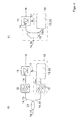
- FIG. 2 a passive optical network is shown, which is operated by a method according to the invention.
- the optical network is similar to the known network FIG. 1 the central data distribution point 10, a passive splitter 12 and a plurality of data receivers 11.
- Each data receiver 11 is now assigned a wake-up unit 16, which is also connected to the data line.
- a data payload packet 14 provided with the number 1 is intended for the first data receiver ONT 1.
- Upstream of the data payload packet 14 or also parallel to a specific further wavelength is sent an optical wake-up 15 as a wake-up signal, which is sent over the same optical line, via which the data payload signal 14 is sent.
- the wake-up signal can also be sent in parallel, eg with a different wavelength.
- the wake-up unit 16 which is assigned to the first data receiver ONT 1, recognizes the wake-up signal 15 as intended for it and thereupon outputs the wake-up command 17 to the first data receiver 11, which then changes from sleep mode to receive mode.
- the other waking units 16 do not issue a wake-up command.
- the other data receivers ONT 2 and ONT 3 remain in sleep mode. It can be seen that in the case where several hundred data receivers 11 are provided in a network, all the data receivers 11 can remain in one of the sleep modes except for one, which will result in enormous energy savings.
- a data payload packet 14 may be sent to and received by one (or more) of the other data receivers ONT 2, Location 3 become.
- FIG. 3 an exemplary structure of the wake-up unit 16 is shown in more detail in a first embodiment.
- An optical wake-up signal 15 impinges upon the wake-up unit 16.
- An optical filter 18 within the wake-up unit 16 modifies the wake-up signal 15 into a modified optical wake-up signal 15m.
- the filter unit 18 may be a fiber Bragg grating which requires no external power supply.
- the optically modified signal 15m is generated in such a way that it temporarily has a higher amplitude than the original optical wake-up signal 15.
- the modified optical wake-up signal 15m then strikes a photodiode 19, which generates an electrical wake-up signal 15e in analogy to outputs optical signal.
- a threshold circuit 20 detects whether the electrical signal 15e has a certain intensity, for example a certain current intensity or voltage, and then if necessary allows a current flow to pass as the electrical wake-up signal 15e, which then represents the wake-up command 17.
- FIG. 4 an alternative embodiment of the wake-up unit is shown.
- an optical energy splitter 21 is provided, which divides the energy of the incident light signal 14, 15; one part is directed towards the wake-up unit 16, the other part is directed to the associated data receiver 11. In both parts but all information of the incident light beam 13 are included.
- the light signal 14, 15 (data-use signal and wake-up signal) is then filtered in both channels by a wavelength filter 18;
- a wavelength filter 18 Within the waking unit 16, only the modified wake-up signal 1 5m remains, which is forwarded to the photodiode 19 and the floating value circuit 20, which is essentially analogous to FIG. 3 can be configured.
- all wake-up commands 15 initially strike the filter unit 18, whereby only those wake-up signals 15m due to their specific wavelength are transmitted, which are also provided for the corresponding data receiver 11. Should then be generated by the photodiode and the threshold circuit, a current flow with a certain minimum current, so this is the wake-up command 17, which is forwarded to the data receiver 11.
- the data receiver 11 is preceded by a wavelength-selective filter 18, which is, however, for the operation of the wake-up unit 16 is not important. Rather, it is ensured in the present case that only data payload packets 14 and not the wake-up signal to the data receiver 11 are allowed to pass.
- FIG. 4b is a modification of the arrangement according to FIG. 4a shown.
- a wavelength-selective filter 18 is used to split the incident light beams 14, 15.
- the modified wake-up signal 15m which is obtained by filtering the original wake-up signal 15 by wavelength, is forwarded to the photodiode 19 and to the threshold circuit 20, which is also analogous to the FIG. 3 can be configured.
- the data payload packets 14 are forwarded only to the data receiver 11, which is transferred as needed by the wake-up command 17 in the receive mode.
- the wave-length-selective filter 18 after the FIGS. 4a and 4b require no additional external energy for operation.
Landscapes
- Engineering & Computer Science (AREA)
- Computer Networks & Wireless Communication (AREA)
- Optical Communication System (AREA)
- Small-Scale Networks (AREA)
- Manufacture, Treatment Of Glass Fibers (AREA)
- Glass Compositions (AREA)
Abstract
Description
Die Erfindung betrifft ein Verfahren zum Betreiben eines optischen Netzes.The invention relates to a method for operating an optical network.
Die Erfindung ist insbesondere anwendbar bei sogenannten passiven optischen Netzen (PON), bei denen hinter der Datenverteifungssteffe zumindest ein passiver Signalsplitter angeordnet ist, der ohne eine eigene Stromversorgung auskommt. Der passive Signalsplitter ist vorgesehen, um ein eingehendes Datensignal in mehrere ausgehende Datenströme aufzuteilen, so dass die Daten durch mehrere Datenempfänger gleichzeitig empfangen werden können. Im Gegensatz dazu weist ein aktives optisches Netz solche Splitter auf, die die Daten aktiv auf einzelne Datenempfänger verteilen und dabei insbesondere nur solche Daten an einen bestimmten Datenempfänger leiten, welche auch explizit für diesen Datenempfänger bestimmt sind.The invention is particularly applicable to so-called passive optical networks (PON), in which behind the Datenverteifungssteffe at least a passive signal splitter is arranged, which manages without its own power supply. The passive signal splitter is provided to divide an incoming data signal into multiple outgoing data streams so that the data can be received by multiple data receivers simultaneously. In contrast to this, an active optical network has such splitters which actively distribute the data to individual data receivers and, in particular, only pass such data to a specific data receiver, which are also explicitly intended for this data receiver.
Der Energieverbrauch eines optischen Netzes wird immer mehr zu einem wichtigen Thema. Dies ist auch dadurch bedingt, dass in einem optischen Netz eine überaus große Zahl an Komponenten angeschlossen werden können, und dass der Kostendruck für den Betrieb der Komponenten beträchtlich ist. Es ist daher ein wesentlicher Aspekt bei der Entwicklung von optischen Netzen, dass diese möglichst energiesparend und damit auch kostengünstig zu betreiben sind.The energy consumption of an optical network is becoming more and more of an important topic. This is also due to the fact that in an optical network an extremely large number of components can be connected, and that the cost pressure for the operation of the components is considerable. It is therefore an essential aspect of the development of optical networks that they are as energy-efficient and therefore cost-effective to operate.
Hauptverbindungen zwischen einzelnen Vermittlungsstellen werden häufig als Punkt-zu-Punkt-Verbindungen ausgeführt, wobei diese Verbindung einem ständigen Datenstrom zwischen den einzelnen Anschlussstellen ausgesetzt sind. Ein Zugangsnetz, für das die Erfindung in besonderem Maße geeignet ist, nämlich ein solches, bei dem auch Heimanschlüsse oder Nutzeranschlüsse direkt angeschlossen werden können, verfügt hingegen über eine enorme Anzahl von Verbindungsstellen, die nur zeitweilig die verfügbare Datenverbindung auch wirklich nutzen. Ein privater lnternetanschluss wird beispielsweise vermehrt am Abend genutzt, während er ansonsten lediglich in Bereitschaft ist; dennoch muss der Internetanschluss auch in den anderen Stunden stets darauf gefasst sein, mögliche Anfragen aus dem Netz entgegennehmen zu müssen. Dies trifft natürlich auch in zeitlich kürzeren Rahmen zu, wenn zwar der Internetanschluss aktiv genutzt wird, dennoch immer mal wieder einzelne Sekunden oder Minuten bzw. Bruchteile davon vergehen, ohne dass tatsächlich ein Datenverkehr mit dem Endgeräteanschluss stattfindet.Main connections between individual exchanges are often executed as point-to-point connections, whereby these connections are exposed to a continuous data stream between the individual connection points. An access network for which the invention is particularly suitable, namely one in which home connections or user connections can be connected directly, on the other hand, has an enormous number of connection points, which only temporarily use the available data connection. For example, a private Internet connection is increasingly used in the evening, while otherwise only on standby; Nevertheless, the Internet connection must always be prepared in the other hours to be able to accept possible inquiries from the network. Of course, this also applies in a shorter time frame, although the Internet connection is actively used, nevertheless sometimes single seconds or minutes or fractions of it pass, without actually a data traffic with the terminal connection takes place.
In passiven sternförmigen Zugangsnetzen wird von einem zentralen Datenverteiter ein Datenstrom stets an alle Datenempfänger gesendet; die einzelnen Datenempfänger entscheiden dann selbständig, ob der Datennutzstrom (oder einzelne Nutzpakete dieses Datenstroms) für sie bestimmt ist oder nicht. Die Wahrscheinlichkeit, dass ein Datenpaket aber für einen einzelnen Datenempfänger bestimmt ist, sinkt zunehmend mit der Zahl der im Netz vorhandenen Datenempfänger. Dennoch müssen alle Datenempfänger stets in der Lage sein, Datennutzsignale zu empfangen.In passive star-shaped access networks, a data stream is always sent to all data recipients by a central data handler; the individual data receivers then decide independently whether or not the data user stream (or individual payload packets of this data stream) is intended for them. However, the likelihood that a data packet is destined for a single data receiver will increasingly decrease with the number of data receivers in the network. Nevertheless, all data receivers must always be able to receive data payloads.
Die passiven optischen Netze werden vermehrt eingesetzt, da die anfallenden Betriebskosten für den Netzbetreiber häufig günstiger sind als die Betriebskosten von aktiven optischen Netzen; davon ausgenommen können die Kosten des Energieverbrauchs sein, die den Inhabern der Datenempfänger entstehen, also insbesondere die Inhaber eines privaten optischen Internetanschlusses.The passive optical networks are increasingly used, since the operating costs incurred by the network operator are often cheaper than the operating costs of active optical networks; The costs of energy consumption incurred by the holders of the data receivers, in particular holders of a private optical Internet connection, may be excluded.
Die
Es ist Aufgabe der vorliegenden Erfindung, ein verbessertes Verfahren zum Betreiben eines optischen Netzes, insbesondere eines passiven optischen Netzes bereit zu stellen. Die der Erfindung zugrunde liegende Aufgabe wird gelöst durch ein Verfahren nach Anspruch 1; bevorzugte Ausgestaltung ergeben sich aus den Unteransprüchen.It is an object of the present invention to provide an improved method for operating an optical network, in particular a passive optical network. The object underlying the invention is achieved by a method according to
Der Kern der Erfindung liegt insbesondere darin, dass ein spezielles optisch kodiertes Aufwecksignal gleichzeitig an mehrere, insbesondere an alle Aufweckeinheiten im Netz, gesendet wird, die jeweils einem Datenempfänger zugeordnet sind. Dabei kann es durchaus möglich sein, dass eine Aufweckeinheit für mehrere Datenempfänger zuständig ist. Jede einzelne Aufweckeinheit kann dann überprüfen, ob das Aufwecksignal für einen Datenempfänger bestimmt ist, der dieser Aufweckeinheit zugeordnet ist. Das Besondere ist nun, dass die Aufweckeinheit eine Filtereinheit aufweist, die rein passiv funktioniert und das optische Signal dekodieren kann bzw. derart modifizieren kann, dass es von einem nachgeordneten lichtempfindlichen Sensor erkannt werden kann. Dem lichtempfindlichen Sensor kann eine Schwellwertschaltung zugeordnet sein, so dass erst eine bestimmte Intensität des auf den lichtempfindlichen Sensor auftreffenden Lichtsignals auch tatsächlich einen Aufweckbefehl erzeugt, der dann an einen zugeordneten Datenempfängern ausgegeben werden kann. Der Vorteil liegt nun darin, dass es durch ein derartiges Verfahren ermöglicht wird, dass die Filtereinheit keine externe Energiezufuhr benötigt und damit im Wesentlichen keine Standbykosten verursacht. Der lichtempfindliche Sensor kann mit einem (wenn überhaupt) sehr geringem Energieaufwand in ständiger Bereitschaft gehalten werden; insbesondere wartet der lichtempfindliche Sensor stets darauf, ob von der Filtereinheit das modifizierte Aufwecksignal ausgegeben wird. Im einfachsten Fall kann der lichtempfindliche Sensor eine Photovoltaikzelle sein, die vollständig ohne zusätzliche externe Energie auskommt. Sobald ein Licht von gewisser Intensität auf die Photovoltaikzelle auftrifft, wird ein Strom ausgegeben oder eine Spannung erzeugt. Ist dieser Strom bzw. die Spannung dann größer als ein vorgegebener Grenzwert, so stellt der Strom bzw. die Spannung selbst den Aufweckbefehl dar. Eine Schnittstelle des Datenempfänger erkennt dann diesen Aufweckbefehl und kann den Datenempfänger vom Schlafmodus in den Bereitschaftsmodus schalten, sofern der Datenempfänger denn zuvor im Schlafmodus war. In gleicher Art kann dieser Datenempfänger auch wieder in den Schlafmodus versetzt werden.The essence of the invention is in particular that a special optically encoded wake-up signal is sent simultaneously to several, in particular to all wake-up units in the network, which are each assigned to a data receiver. It may well be possible for a wake-up unit to be responsible for several data recipients. each individual waking unit can then check whether the wake-up signal is intended for a data receiver, which is assigned to this waking unit. The special feature is that the wake-up unit has a filter unit which functions purely passive and can decode or modify the optical signal so that it can be recognized by a downstream photosensitive sensor. The light-sensitive sensor may be associated with a threshold circuit, so that only a certain intensity of the incident on the light-sensitive sensor light signal actually generates a wake-up command, which can then be output to an associated data receivers. The advantage lies in the fact that it is made possible by such a method that the filter unit requires no external power supply and thus causes substantially no standby costs. The photosensitive sensor can be kept in constant readiness with (if at all) very little energy expenditure; In particular, the photosensitive sensor always waits for the filter unit to output the modified wake-up signal. In the simplest case, the photosensitive sensor can be a photovoltaic cell, which manages completely without additional external energy. As soon as a light of a certain intensity hits the photovoltaic cell, a current is output or a voltage is generated. If this current or the voltage is then greater than a predetermined limit value, the current or the voltage itself represents the wake-up command. An interface of the data receiver then recognizes this wake-up command and can switch the data receiver from sleep mode to standby mode, provided the data receiver is was previously in sleep mode. In the same way, this data receiver can also be put back into sleep mode.
Das Verfahren zum Aufwecken kann dabei vollständig ohne informationstechnische Aufarbeitung des Aufwecksignals auskommen. Im Gegensatz zu herkömmlichen Anwendungen, in denen stets das optische Signal zunächst datentechnisch zu analysieren ist, ob denn in dem optischen Signal ein relevanter Aufweckbefehl versteckt ist, kann das Erkennen des Aufwecksignals nun von jeder einzelnen Aufweckeinheit rein passiv durchgeführt werden, was den Energiebedarf der Anordnung aus Aufweckeinheit und Datenempfänger im Schlafmodus enorm reduziert.The method for waking can thereby manage completely without information processing of the wake-up signal. In contrast to conventional applications in which the optical signal is always first to be analyzed by data technology, if a relevant wake-up command is hidden in the optical signal, the detection of the wake-up signal can now be carried out purely passively by each individual wake-up unit, which reduces the energy requirement of the arrangement from waking unit and data receiver in sleep mode enormously reduced.
Besonders bevorzugt ist es, wenn die Filtereinheit im Betrieb ohne den zusätzlichen Einsatz von externer Energie auskommt; selbstverständlich davon ausgenommen ist die Lichtenergie des optischen Datenstroms, die sowieso durch die optische Leitung auf die Filtereinheit trifft. Dabei ist es besonders bevorzugt, wenn die zur Erzeugung des Aufweckbefehles erforderliche Energie vollständig dem optisch modifizierten Aufvvecksignal entnommen wird. Sollte beispielsweise wie beschrieben die Umwandlung von optischem Aufwecksignal in den elektrischen oder in elektronischen Aufweckbefehl mit Hilfe einer Photovoltaikzelle erfolgen, so wird die elektrische Energie des Aufweckbefehls vollständig durch Umwandlung der optischen Energie des optischen Aufwecksignals erzeugt.It is particularly preferred if the filter unit manages in operation without the additional use of external energy; Of course, the light energy of the optical data stream, which anyway strikes the filter unit through the optical line, is excluded from this. It is particularly preferred if the energy required for generating the wake-up command is completely removed from the optically modified up-signal. For example, if, as described, the conversion of the optical wake-up signal into the electrical or electronic wake-up command is by means of a photovoltaic cell, the electrical energy of the wake-up command is completely generated by converting the optical energy of the optical wake-up signal.
In einer bevorzugten Ausgestaltung gibt die Filtereinheit derjenigen Aufweckeinheit, die dem bestimmten Datenempfänger des Aufwecksignals zugeordnet ist, ein modifiziertes Aufwecksignal aus, weiches zumindest temporär eine höhere Amplitude aufweist, als die von anderen Filtereinheiten modifizierten Aufwecksignafe desselben ursprünglichen Aufwecksignals. Falls sich eine der Aufweckeinheiten durch das Aufwecksignal "angesprochen fühlt", erzeugt diese angesprochene Filtereinheit aus dem Aufwecksignal ein solches modifiziertes Aufwecksignal, welches sich in der Lichtintensität von dem ursprünglichen Aufwecksignal unterscheidet, nämlich durch eine höhere Lichtintensität. Hierzu können beispielsweise ein Faser-Bragg-Gitter, insbesondere ein super strukturiertes Faser-Bragg-Gitter, und/oder optische Verzögerungsstrukturen verwendet werden. Der lichtempfindliche Sensor ist dann auf die temporär höhere Amplitude des modifizierten Aufwecksignals konditioniert und kann dann den entsprechenden Aufweckbefehl ausgeben. Also nur wenn das modifizierte optische Signal über die erhöhte Intensität verfügt, wird ein vorgegebener Schwellwert auch erreicht, so dass ein valider Aufweckbefehl erzeugt werden kann, insbesondere ohne den Einsatz externer Energie. Damit kann sicher gestellt werden, dass der optische Sensor zwar auf das modifizierte optische Signal anspringt, nicht aber auf jegliche Aufwecksignale, die von der Datenverteilungsstelle ausgesendet werden. Mit anderen Worten ist die Filtereinheit in dieser Ausgestaltung eine Art temporärer optischer Verstärker, der nur dann eine Verstärkung erzeugt oder bewirkt, wenn das auftreffende Aufwecksignal auch tatsächlich für den zugehörigen Datenempfänger bestimmt ist.In a preferred embodiment, the filter unit outputs to the wake-up unit associated with the particular data receiver the wake-up signal a modified wake-up signal at least temporarily having a higher amplitude than the wake-up signals of the same original wake-up signal modified by other filter units. If one of the waking units "feels" addressed by the wake-up signal, this addressed filter unit generates from the wake-up signal such a modified wake-up signal, which differs in light intensity from the original wake-up signal, namely by a higher light intensity. For this purpose, for example, a fiber Bragg grating, in particular a super-structured fiber Bragg grating, and / or optical delay structures can be used. The photosensitive sensor is then conditioned to the temporarily higher amplitude of the modified wake-up signal and can then output the corresponding wake-up command. So only if the modified optical signal has the increased intensity, a predetermined threshold is also reached, so that a valid wake-up command can be generated, in particular without the use of external energy. It can thus be ensured that the optical sensor does indeed respond to the modified optical signal, but not to any wake-up signals that are transmitted by the data distribution point. In other words, the filter unit in this embodiment is a kind of temporary optical amplifier which only generates or effects amplification if the impinging wake-up signal is actually intended for the associated data receiver.
In einer alternativen Ausgestaltung ist die Filtereinheit eine wellenlängenselektive Filtereinheit. Die für die unterschiedlichen Aufweckeinheiten vorgesehenen Aufwecksignale werden dann durch unterschiedliche Wellenlängen individualisiert. So kann die wellenlängeselektive Filtereinheit einen Signalsplitter und einen nachgelagerte Wellenlängenfilter umfassen oder einen wellenlängenselektiven Splitter umfassen. Jedem Datenempfänger wird damit ein optisches Aufwecksignal mit einer speziellen Frequenz zugewiesen. Der Filter lässt dann nur solche Aufimecksignale zu der jeweiligen Aufweckeinheit und dem optischen Sensor gelangen, welche für den jeweiligen Datenempfänger auch bestimmt sind. Dann kann der optische Sensor wie oben beschrieben erkennen, dass ein Lichtsignal mit einer entsprechenden Amplitude auf ihn auftrifft, Sollte die Lichtintensität eine gewisse Stärke aufweisen, so dass ein Schwellwert überschritten ist, so wird der Aufweckbefehl an den Datenempfänger ausgegeben. Beide beschriebenen Verfahren können auch kombiniert werden, um die Zahl der zu unterscheidenden Datenempfänger weiter zu erhöhen.In an alternative embodiment, the filter unit is a wavelength-selective filter unit. The wake-up signals provided for the different wake-up units are then individualized by different wavelengths. Thus, the wavelength-selective filter unit may comprise a signal splitter and a downstream wavelength filter or comprise a wavelength-selective splitter. Each data receiver is thus assigned an optical wake-up signal with a specific frequency. The filter then allows only such Aufimecksignale to reach the respective Aufweckeinheit and the optical sensor, which are also intended for the respective data receiver. Then, as described above, the optical sensor can detect that a light signal having a corresponding amplitude impinges on it Light intensity have a certain strength, so that a threshold is exceeded, the wake-up command is issued to the data receiver. Both described methods can also be combined to further increase the number of data receivers to be distinguished.
Als mögliche Filtereinheiten eignen sich grundsätzlich ein Faser-Bragg-Gitter, eine Verzögerungsstruktur (delay-line interferometer) oder andere optische Strukturen mit endlicher, teilweise auch unendlicher Impulsantwort (FIR- bzw. IIR-Filter).As a possible filter units are basically a fiber Bragg grating, a delay structure (delay-line interferometer) or other optical structures with finite, sometimes even infinite impulse response (FIR or IIR filter).
In einer bevorzugten Weiterbildung kann das für einen bestimmten Datenempfänger bestimmte Aufwecksignal zeitgleich zu einem Datennutzsignal gesendet wird, welches zum Empfang durch einen anderen Datenempfänger vorgesehen ist. Dabei kann das Aufwecksignal auf einer Frequenz gesendet werden, die ausschließlich diesem Aufwecksignal vorbehalten ist. Insofern wird das Netz nicht durch das Versenden des Aufwecksignals vollständig blockiert, sondern kann durchgehend weiter für den Versand der Datennutzsignale verwendet werden.In a preferred refinement, the wake-up signal, which is intended for a particular data receiver, can be sent at the same time as a data-use signal, which is provided for reception by another data receiver. In this case, the wake-up signal can be sent on a frequency which is reserved exclusively for this wake-up signal. As such, the network is not completely blocked by sending the wake-up signal but can continue to be used to send the data payloads.
Die Erfindung betrifft ferner ein Datennetz, insbesondere ein optisches Datennetz, weiches mittels eines Verfahrens der vorgenannten Art betrieben wird. Das betreffende Datennetz ist insbesondere ein passives optisches Datennetz, insbesondere ein sternförmiges Datennetz.The invention further relates to a data network, in particular an optical data network, which is operated by means of a method of the aforementioned type. The relevant data network is in particular a passive optical data network, in particular a star-shaped data network.
Die Erfindung wird anhand der Figuren nachfolgend näher erläutert:
Figur 1- die Struktur eines bekannten passiven optischen Netzes (PON);
Figur 2- die Struktur eines erfindungsgemäß betriebenen optischen Netzes;
Figur 3- Einzelheiten einer Aufweckeinheit in dem Netz nach
Figur 2 - Figur 4
- Einzelheiten einer Aufweckeinheit in dem
Netz nach Figur 2 in einer zweiten Ausgestaltung;
- FIG. 1
- the structure of a known passive optical network (PON);
- FIG. 2
- the structure of an optical network operated according to the invention;
- FIG. 3
- Details of a wake-up unit in the network
FIG. 2 in a first embodiment; - FIG. 4
- Details of a wake-up unit in the network
FIG. 2 in a second embodiment;
In
In
In
In der
Sollten die anderen Datenempfänger durch einen vorherigen Aufweckbefehl aufgeweckt sein, so kann zeitgleich zum Aufwecksignal 15, welches für den Datenempfänger ONT 1 bestimmt ist, ein Datennutzpaket 14 an einen (odere mehrere) der anderen Datenempfänger ONT 2, Ort 3 gesendet werden und von diesen empfangen werden.Should the other data receivers be awakened by a previous wake-up command, at the same time as the wake-
In
In
Das Lichtsignal 14, 15 (Datennutzsignal und Aufwecksignal) wird in beiden Kanälen dann durch einen Wellenlängenfilter 18 gefiltert; so bleibt innerhalb der Aufweckeinheit 16 nur noch das modifizierte Aufwecksignal 1 5m übrig, welches an die Fotodiode 19 und die Schweilwertschaltung 20 weitergeleitet wird, die im Wesentlichen analog zur
Auch dem Datenempfänger 11 ist ein wellenlängenselektiver Filter 18 vorgeschaltet, der allerdings für die Funktionsweise der Aufweckeinheit 16 nicht von Bedeutung ist. Vielmehr wird im vorliegenden Fall sichergestellt, dass nur Datennutzpakete 14 und nicht noch das Aufwecksignal zum Datenempfänger 11 durchgelassen werden.Also, the
In
- 1010
- DatenverteilungsstelleData distribution point
- 1111
- Datenempfängerdata receiver
- 1212
- Splittersplinter
- 1313
- Datenstromdata stream
- 1414
- DatennutzpaketDatennutzpaket
- 1515
- Aufwecksignalwake-up
- 1616
- AufweckeinheitAufweckeinheit
- 1717
- Aufweckbefehlwake-up
- 1818
- optischer Filteroptical filter
- 1919
- Fotodiodephotodiode
- 2020
- Schwellwertschaltungthreshold
- 2121
- optischer Energiesplitteroptical energy splitter
Claims (11)
wobei die Datenempfänger (11) wahlweise einen Empfangsmodus und einen Schlafmodus einnehmen können, wobei im Empfangsmodus der Empfang und die Verarbeitung von Datennutzsignalen (14) grundsätzlich möglich ist und im Schlafmodus der Empfang von Datennutzsignalen (14) oder die Verarbeitung empfangene Datennutzsignale (14) nicht möglich ist,
dadurch gekennzeichnet,
dass einzelne Datenempfänger (11) durch ein datenempfängerspezifisches Aufwecksignal (15) veranlasst werden, vom Schlafmodus in den Empfangsmodus zu wechseln,
dass das Aufwecksignal (15) ein optisches Signal ist, das von einer Aufweckanordnung (16) empfangen wird, die jeweils einem der Datenempfänger (11) zugeordnet ist,
dass nur für den Fall, dass das Aufwecksignal (15) für den zughörigen Datenempfänger (11) bestimmt ist und der zugehörige Datenempfänger nicht im Empfangsmodus ist, folgende Schritte in angegebener Reihenfolge erfolgen:
wherein the data receivers (11) can optionally assume a receive mode and a sleep mode, wherein in the receive mode the reception and processing of data payload signals (14) is basically possible and in the sleep mode the reception of data payload signals (14) or the data received data processing (14) received the processing is possible,
characterized,
that individual data receiver (11) are initiated by a data receiver specific wake-up signal (15) to switch from the sleep mode to the reception mode,
that the wake-up signal (15) is an optical signal from a Aufweckanordnung (16) is received that is associated with each one of said data receiver (11),
that only in the event that the wake-up signal (15) for the associated data receiver (11) is determined and the associated data receiver is not in the receive mode, the following steps in the order given:
dadurch gekennzeichnet,
dass die Filtereinheit (18) das modifizierte optische Aufwecksignal (15m) ohne den Einsatz von zusätzlicher externer Energie erzeugt.Method according to the previous claim,
characterized,
that the filter unit (18) generates the modified optical wake-up signal (15 m) without the use of additional external energy.
dadurch gekennzeichnet,
dass die zur Erzeugung des Aufweckbefehls (17) erforderliche Energie vollständig dem optischen modifizierten Aufwecksignal (15m) entnommen wird.Method according to one of the preceding claims,
characterized,
in that the energy required to generate the wake-up command (17) is completely removed from the optically modified wake-up signal (15m).
dadurch gekennzeichnet,
dass die Filtereinheit (18) derjenigen Aufweckeinheit (16), die dem bestimmten Datenempfänger (11) des Aufwecksignals (15) zugeordnet ist, ein modifiziertes Aufwecksignal (15m) erzeugt, welches zumindest temporär eine höhere Amplitude aufweist als von anderen Filtereinheiten (16) modifizierte Aufwecksignale (15m) basierend auf demselben ursprünglichen Aufwecksignal (15), und
dass der lichtempfindlichen Sensor (19) auf die temporär höhere Amplitude des modifizierten Aufwecksignals (15m) konditioniert ist.Method according to one of the preceding claims,
characterized,
in that the filter unit (18) of the waking unit (16) associated with the particular data receiver (11) of the wake-up signal (15) generates a modified wake-up signal (15m) which at least temporarily has a higher amplitude than that modified by other filter units (16) Wake-up signals (15m) based on the same original wake-up signal (15), and
that the light-sensitive sensor (19) is conditioned on the temporarily higher amplitude of the modified wake-up signal (15m).
dadurch gekennzeichnet,
dass das modifizierte Aufwecksignal (15m) temporär eine höhere Amplitude aufweist als das ursprüngliche Aufwecksignal (15), und
dass der lichtempfindlichen Sensor (19) auf die temporär höhere Amplitude des modifizierten Aufwecksignals (15m) konditioniert ist.Method according to one of the preceding claims,
characterized,
that the modified wake-up signal (15m) temporarily has a higher amplitude than the original wake-up signal (15), and
that the light-sensitive sensor (19) is conditioned on the temporarily higher amplitude of the modified wake-up signal (15m).
dadurch gekennzeichnet,
dass die für unterschiedliche Datenempfänger (11) bestimmte einzelne Aufwecksignale (15) durch unterschiedliche Wellenlängen individualisiert werden, und dass die Filtereinheit (18) wellenlängenselektiv ausgebildet ist.Method according to one of the preceding claims,
characterized,
in that the individual wake-up signals (15) intended for different data receivers (11) are individualized by different wavelengths, and in that the filter unit (18) is designed to be wavelength-selective.
dadurch gekennzeichnet,
dass die wellenlängenselektive Filtereinheit (18)
characterized,
in that the wavelength-selective filter unit (18)
dadurch gekennzeichnet,
dass die Filtereinheit (18) ein Faser-Bragg-Gitter, insbesondere ein superstrukturiertes Faser-Bragg-Gitter, eine Verzögerungsstruktur (delay-lineinterferometer) oder optische Strukturen mit endlicher oder teilweise unendlicher lmpulsantwort (FIR- bzw. IIR-Filter) umfasst.Method according to one of the preceding claims,
characterized,
in that the filter unit (18) comprises a fiber Bragg grating, in particular a super-structured fiber Bragg grating, a delay-line interferometer or finite or partially infinite impulse response (FIR or IIR) optical structures.
dadurch gekennzeichnet,
dass das für einen bestimmten Datenempfänger bestimmte Aufwecksignal (15) vor dem Versenden eines an den bestimmten Datenempfänger bestimmten Datennutzsignals (14) ausgesendet wird, und dass der anhand dieses Aufwecksignals (15) in den Empfangsmodus überführte Datenempfänger (11) unmittelbar nach dem Wechsel in den Empfangsmodus ein Datennutzsignal (14) empfängt und verarbeitet.Method according to one of the preceding claims,
characterized,
in that the wake-up signal (15) intended for a particular data receiver is transmitted prior to sending a data useful signal (14) destined for the particular data receiver, and in that the data receiver (11) transferred into receive mode on the basis of this wake-up signal (15) immediately after the change to the Receive mode, a Datenennutzsignal (14) receives and processes.
dadurch gekennzeichnet,
dass das für einen bestimmten Datenempfänger bestimmte Aufwecksignal (15) zeitgleich zu einem Datennutzsignal (14) gesendet wird, weiches zum Empfang durch einen anderen Datenempfänger vorgesehen ist.Method according to one of the preceding claims,
characterized,
in that the wake-up signal (15) intended for a particular data receiver is transmitted at the same time as a data-use signal (14) intended to be received by another data receiver.
Priority Applications (5)
| Application Number | Priority Date | Filing Date | Title |
|---|---|---|---|
| PL12187433.3T PL2717592T3 (en) | 2012-10-05 | 2012-10-05 | Method for operating an optical network |
| HUE12187433A HUE029467T2 (en) | 2012-10-05 | 2012-10-05 | Method for operating an optical network |
| EP12187433.3A EP2717592B1 (en) | 2012-10-05 | 2012-10-05 | Method for operating an optical network |
| ES12187433.3T ES2581302T3 (en) | 2012-10-05 | 2012-10-05 | Method of operation of an optical network |
| HRP20160755TT HRP20160755T1 (en) | 2012-10-05 | 2016-06-27 | Method for operating an optical network |
Applications Claiming Priority (1)
| Application Number | Priority Date | Filing Date | Title |
|---|---|---|---|
| EP12187433.3A EP2717592B1 (en) | 2012-10-05 | 2012-10-05 | Method for operating an optical network |
Publications (2)
| Publication Number | Publication Date |
|---|---|
| EP2717592A1 true EP2717592A1 (en) | 2014-04-09 |
| EP2717592B1 EP2717592B1 (en) | 2016-04-06 |
Family
ID=47325815
Family Applications (1)
| Application Number | Title | Priority Date | Filing Date |
|---|---|---|---|
| EP12187433.3A Active EP2717592B1 (en) | 2012-10-05 | 2012-10-05 | Method for operating an optical network |
Country Status (5)
| Country | Link |
|---|---|
| EP (1) | EP2717592B1 (en) |
| ES (1) | ES2581302T3 (en) |
| HR (1) | HRP20160755T1 (en) |
| HU (1) | HUE029467T2 (en) |
| PL (1) | PL2717592T3 (en) |
Citations (3)
| Publication number | Priority date | Publication date | Assignee | Title |
|---|---|---|---|---|
| US7389528B1 (en) * | 2002-12-17 | 2008-06-17 | Juniper Networks, Inc. | Operating cable modems in a low power mode |
| EP2104250A1 (en) | 2008-03-18 | 2009-09-23 | Alcatel Lucent | Method for monitoring a passive optical network using monitoring units |
| WO2012034385A1 (en) * | 2010-09-17 | 2012-03-22 | 中兴通讯股份有限公司 | Method and system for realizing power saving mechanism management between optical network unit (onu) and optical line terminal (olt) |
-
2012
- 2012-10-05 HU HUE12187433A patent/HUE029467T2/en unknown
- 2012-10-05 PL PL12187433.3T patent/PL2717592T3/en unknown
- 2012-10-05 ES ES12187433.3T patent/ES2581302T3/en active Active
- 2012-10-05 EP EP12187433.3A patent/EP2717592B1/en active Active
-
2016
- 2016-06-27 HR HRP20160755TT patent/HRP20160755T1/en unknown
Patent Citations (4)
| Publication number | Priority date | Publication date | Assignee | Title |
|---|---|---|---|---|
| US7389528B1 (en) * | 2002-12-17 | 2008-06-17 | Juniper Networks, Inc. | Operating cable modems in a low power mode |
| EP2104250A1 (en) | 2008-03-18 | 2009-09-23 | Alcatel Lucent | Method for monitoring a passive optical network using monitoring units |
| WO2012034385A1 (en) * | 2010-09-17 | 2012-03-22 | 中兴通讯股份有限公司 | Method and system for realizing power saving mechanism management between optical network unit (onu) and optical line terminal (olt) |
| EP2552084A1 (en) * | 2010-09-17 | 2013-01-30 | ZTE Corporation | Method and system for realizing power saving mechanism management between optical network unit (onu) and optical line terminal (olt) |
Also Published As
| Publication number | Publication date |
|---|---|
| HRP20160755T1 (en) | 2016-08-12 |
| EP2717592B1 (en) | 2016-04-06 |
| ES2581302T3 (en) | 2016-09-05 |
| HUE029467T2 (en) | 2017-02-28 |
| PL2717592T3 (en) | 2016-10-31 |
Similar Documents
| Publication | Publication Date | Title |
|---|---|---|
| EP2011257B1 (en) | Protection device for removal of signal interference in a passive optical network | |
| EP0505829B1 (en) | System for optical signal transmission, particularly optical cable TV system, with monitoring and service channel device | |
| EP1464205A2 (en) | Device and method for transmitting, receiving and processing audio control signals in information systems | |
| DE102012224031A1 (en) | Data transfer protocol with log exception state | |
| EP2717592B1 (en) | Method for operating an optical network | |
| EP2843486B1 (en) | Method and apparatus for synchronising a control unit and at least one associated peripheral unit | |
| DE102013109544B4 (en) | Two electronic device wake-up circuits and electronic device wake-up procedures | |
| EP0433481B1 (en) | Method for bidirectionally transmitting optical signals over optical fiber conductors | |
| EP0973295A2 (en) | Point-to-multipoint network | |
| DE102017217301A1 (en) | Method and device for the direct and feedback-free transmission of log messages | |
| DE60122690T2 (en) | POWER CONTROL NETWORK ELEMENT | |
| EP2832046B1 (en) | Method and apparatus for communicating in wind farms | |
| DE2718473C3 (en) | Circuit arrangement for the parallel transmission of signals over several parallel lines | |
| DE10340104B4 (en) | Method and system for efficient transmission of power in the sound of rooms | |
| DE102005061395A1 (en) | Active star point for use in a communication system with star topology | |
| EP1632055B1 (en) | Method for transmitting a user data record to a user station | |
| EP1455489A2 (en) | Traffic load optimization in a communications network | |
| EP1654832B1 (en) | Method for establishing a device of a data network as pilot master | |
| DE3142924C2 (en) | Optical transmission system with limited transmission bandwidth in the event of a power failure | |
| DE102012018616A1 (en) | Method for transferring energy and information from transmission to receiver modules, has detectors to receive laser beams, such that correlation of wavelengths signals is used to detect whether data is sent to receiver module | |
| AT507204B1 (en) | METHOD AND APPENDIX FOR DISTRIBUTING INSERTED DATA | |
| EP2621195B1 (en) | Passive optical networks with mixed bit rates by the use of an integer divider of a maximum data rate for the dynamic adaptation of bit rate in ongoing operation | |
| DE102012103201B3 (en) | Method for signaling states and / or events of domestic appliances by means of a door communication system | |
| EP1139691B1 (en) | Busstation for an optical bus system | |
| EP3706388A1 (en) | Method for providing a cryptographic key |
Legal Events
| Date | Code | Title | Description |
|---|---|---|---|
| PUAI | Public reference made under article 153(3) epc to a published international application that has entered the european phase |
Free format text: ORIGINAL CODE: 0009012 |
|
| AK | Designated contracting states |
Kind code of ref document: A1 Designated state(s): AL AT BE BG CH CY CZ DE DK EE ES FI FR GB GR HR HU IE IS IT LI LT LU LV MC MK MT NL NO PL PT RO RS SE SI SK SM TR |
|
| AX | Request for extension of the european patent |
Extension state: BA ME |
|
| 17P | Request for examination filed |
Effective date: 20140924 |
|
| RBV | Designated contracting states (corrected) |
Designated state(s): AL AT BE BG CH CY CZ DE DK EE ES FI FR GB GR HR HU IE IS IT LI LT LU LV MC MK MT NL NO PL PT RO RS SE SI SK SM TR |
|
| RIC1 | Information provided on ipc code assigned before grant |
Ipc: H04Q 11/00 20060101AFI20151020BHEP |
|
| GRAP | Despatch of communication of intention to grant a patent |
Free format text: ORIGINAL CODE: EPIDOSNIGR1 |
|
| INTG | Intention to grant announced |
Effective date: 20151204 |
|
| GRAS | Grant fee paid |
Free format text: ORIGINAL CODE: EPIDOSNIGR3 |
|
| GRAA | (expected) grant |
Free format text: ORIGINAL CODE: 0009210 |
|
| AK | Designated contracting states |
Kind code of ref document: B1 Designated state(s): AL AT BE BG CH CY CZ DE DK EE ES FI FR GB GR HR HU IE IS IT LI LT LU LV MC MK MT NL NO PL PT RO RS SE SI SK SM TR |
|
| REG | Reference to a national code |
Ref country code: GB Ref legal event code: FG4D Free format text: NOT ENGLISH |
|
| REG | Reference to a national code |
Ref country code: AT Ref legal event code: REF Ref document number: 788932 Country of ref document: AT Kind code of ref document: T Effective date: 20160415 Ref country code: CH Ref legal event code: EP |
|
| REG | Reference to a national code |
Ref country code: IE Ref legal event code: FG4D Free format text: LANGUAGE OF EP DOCUMENT: GERMAN |
|
| REG | Reference to a national code |
Ref country code: DE Ref legal event code: R096 Ref document number: 502012006573 Country of ref document: DE |
|
| REG | Reference to a national code |
Ref country code: HR Ref legal event code: TUEP Ref document number: P20160755 Country of ref document: HR |
|
| REG | Reference to a national code |
Ref country code: NL Ref legal event code: FP |
|
| REG | Reference to a national code |
Ref country code: SE Ref legal event code: TRGR |
|
| REG | Reference to a national code |
Ref country code: LT Ref legal event code: MG4D |
|
| REG | Reference to a national code |
Ref country code: HR Ref legal event code: T1PR Ref document number: P20160755 Country of ref document: HR |
|
| REG | Reference to a national code |
Ref country code: NO Ref legal event code: T2 Effective date: 20160406 |
|
| REG | Reference to a national code |
Ref country code: ES Ref legal event code: FG2A Ref document number: 2581302 Country of ref document: ES Kind code of ref document: T3 Effective date: 20160905 |
|
| REG | Reference to a national code |
Ref country code: FR Ref legal event code: PLFP Year of fee payment: 5 |
|
| PG25 | Lapsed in a contracting state [announced via postgrant information from national office to epo] |
Ref country code: FI Free format text: LAPSE BECAUSE OF FAILURE TO SUBMIT A TRANSLATION OF THE DESCRIPTION OR TO PAY THE FEE WITHIN THE PRESCRIBED TIME-LIMIT Effective date: 20160406 Ref country code: LT Free format text: LAPSE BECAUSE OF FAILURE TO SUBMIT A TRANSLATION OF THE DESCRIPTION OR TO PAY THE FEE WITHIN THE PRESCRIBED TIME-LIMIT Effective date: 20160406 Ref country code: IS Free format text: LAPSE BECAUSE OF FAILURE TO SUBMIT A TRANSLATION OF THE DESCRIPTION OR TO PAY THE FEE WITHIN THE PRESCRIBED TIME-LIMIT Effective date: 20160806 |
|
| PG25 | Lapsed in a contracting state [announced via postgrant information from national office to epo] |
Ref country code: PT Free format text: LAPSE BECAUSE OF FAILURE TO SUBMIT A TRANSLATION OF THE DESCRIPTION OR TO PAY THE FEE WITHIN THE PRESCRIBED TIME-LIMIT Effective date: 20160808 Ref country code: LV Free format text: LAPSE BECAUSE OF FAILURE TO SUBMIT A TRANSLATION OF THE DESCRIPTION OR TO PAY THE FEE WITHIN THE PRESCRIBED TIME-LIMIT Effective date: 20160406 Ref country code: GR Free format text: LAPSE BECAUSE OF FAILURE TO SUBMIT A TRANSLATION OF THE DESCRIPTION OR TO PAY THE FEE WITHIN THE PRESCRIBED TIME-LIMIT Effective date: 20160707 Ref country code: RS Free format text: LAPSE BECAUSE OF FAILURE TO SUBMIT A TRANSLATION OF THE DESCRIPTION OR TO PAY THE FEE WITHIN THE PRESCRIBED TIME-LIMIT Effective date: 20160406 |
|
| REG | Reference to a national code |
Ref country code: SK Ref legal event code: T3 Ref document number: E 21491 Country of ref document: SK |
|
| REG | Reference to a national code |
Ref country code: DE Ref legal event code: R097 Ref document number: 502012006573 Country of ref document: DE |
|
| PG25 | Lapsed in a contracting state [announced via postgrant information from national office to epo] |
Ref country code: EE Free format text: LAPSE BECAUSE OF FAILURE TO SUBMIT A TRANSLATION OF THE DESCRIPTION OR TO PAY THE FEE WITHIN THE PRESCRIBED TIME-LIMIT Effective date: 20160406 Ref country code: DK Free format text: LAPSE BECAUSE OF FAILURE TO SUBMIT A TRANSLATION OF THE DESCRIPTION OR TO PAY THE FEE WITHIN THE PRESCRIBED TIME-LIMIT Effective date: 20160406 Ref country code: RO Free format text: LAPSE BECAUSE OF FAILURE TO SUBMIT A TRANSLATION OF THE DESCRIPTION OR TO PAY THE FEE WITHIN THE PRESCRIBED TIME-LIMIT Effective date: 20160406 |
|
| PLBE | No opposition filed within time limit |
Free format text: ORIGINAL CODE: 0009261 |
|
| STAA | Information on the status of an ep patent application or granted ep patent |
Free format text: STATUS: NO OPPOSITION FILED WITHIN TIME LIMIT |
|
| PG25 | Lapsed in a contracting state [announced via postgrant information from national office to epo] |
Ref country code: BE Free format text: LAPSE BECAUSE OF NON-PAYMENT OF DUE FEES Effective date: 20161031 Ref country code: SM Free format text: LAPSE BECAUSE OF FAILURE TO SUBMIT A TRANSLATION OF THE DESCRIPTION OR TO PAY THE FEE WITHIN THE PRESCRIBED TIME-LIMIT Effective date: 20160406 |
|
| REG | Reference to a national code |
Ref country code: HU Ref legal event code: AG4A Ref document number: E029467 Country of ref document: HU |
|
| 26N | No opposition filed |
Effective date: 20170110 |
|
| PG25 | Lapsed in a contracting state [announced via postgrant information from national office to epo] |
Ref country code: SI Free format text: LAPSE BECAUSE OF FAILURE TO SUBMIT A TRANSLATION OF THE DESCRIPTION OR TO PAY THE FEE WITHIN THE PRESCRIBED TIME-LIMIT Effective date: 20160406 |
|
| REG | Reference to a national code |
Ref country code: CH Ref legal event code: PL |
|
| REG | Reference to a national code |
Ref country code: IE Ref legal event code: MM4A |
|
| PG25 | Lapsed in a contracting state [announced via postgrant information from national office to epo] |
Ref country code: CH Free format text: LAPSE BECAUSE OF NON-PAYMENT OF DUE FEES Effective date: 20161031 Ref country code: LI Free format text: LAPSE BECAUSE OF NON-PAYMENT OF DUE FEES Effective date: 20161031 |
|
| PG25 | Lapsed in a contracting state [announced via postgrant information from national office to epo] |
Ref country code: LU Free format text: LAPSE BECAUSE OF NON-PAYMENT OF DUE FEES Effective date: 20161005 |
|
| REG | Reference to a national code |
Ref country code: FR Ref legal event code: PLFP Year of fee payment: 6 |
|
| PG25 | Lapsed in a contracting state [announced via postgrant information from national office to epo] |
Ref country code: IE Free format text: LAPSE BECAUSE OF NON-PAYMENT OF DUE FEES Effective date: 20161005 |
|
| REG | Reference to a national code |
Ref country code: BE Ref legal event code: MM Effective date: 20161031 |
|
| PG25 | Lapsed in a contracting state [announced via postgrant information from national office to epo] |
Ref country code: CY Free format text: LAPSE BECAUSE OF FAILURE TO SUBMIT A TRANSLATION OF THE DESCRIPTION OR TO PAY THE FEE WITHIN THE PRESCRIBED TIME-LIMIT Effective date: 20160406 |
|
| PG25 | Lapsed in a contracting state [announced via postgrant information from national office to epo] |
Ref country code: MK Free format text: LAPSE BECAUSE OF FAILURE TO SUBMIT A TRANSLATION OF THE DESCRIPTION OR TO PAY THE FEE WITHIN THE PRESCRIBED TIME-LIMIT Effective date: 20160406 Ref country code: MC Free format text: LAPSE BECAUSE OF FAILURE TO SUBMIT A TRANSLATION OF THE DESCRIPTION OR TO PAY THE FEE WITHIN THE PRESCRIBED TIME-LIMIT Effective date: 20160406 Ref country code: MT Free format text: LAPSE BECAUSE OF FAILURE TO SUBMIT A TRANSLATION OF THE DESCRIPTION OR TO PAY THE FEE WITHIN THE PRESCRIBED TIME-LIMIT Effective date: 20160406 |
|
| PG25 | Lapsed in a contracting state [announced via postgrant information from national office to epo] |
Ref country code: BG Free format text: LAPSE BECAUSE OF FAILURE TO SUBMIT A TRANSLATION OF THE DESCRIPTION OR TO PAY THE FEE WITHIN THE PRESCRIBED TIME-LIMIT Effective date: 20160406 |
|
| REG | Reference to a national code |
Ref country code: FR Ref legal event code: PLFP Year of fee payment: 7 |
|
| PG25 | Lapsed in a contracting state [announced via postgrant information from national office to epo] |
Ref country code: TR Free format text: LAPSE BECAUSE OF FAILURE TO SUBMIT A TRANSLATION OF THE DESCRIPTION OR TO PAY THE FEE WITHIN THE PRESCRIBED TIME-LIMIT Effective date: 20160406 Ref country code: AL Free format text: LAPSE BECAUSE OF FAILURE TO SUBMIT A TRANSLATION OF THE DESCRIPTION OR TO PAY THE FEE WITHIN THE PRESCRIBED TIME-LIMIT Effective date: 20160406 |
|
| REG | Reference to a national code |
Ref country code: HR Ref legal event code: ODRP Ref document number: P20160755 Country of ref document: HR Payment date: 20190926 Year of fee payment: 8 |
|
| REG | Reference to a national code |
Ref country code: HR Ref legal event code: ODRP Ref document number: P20160755 Country of ref document: HR Payment date: 20200924 Year of fee payment: 9 |
|
| REG | Reference to a national code |
Ref country code: HR Ref legal event code: ODRP Ref document number: P20160755 Country of ref document: HR Payment date: 20210924 Year of fee payment: 10 |
|
| REG | Reference to a national code |
Ref country code: HR Ref legal event code: ODRP Ref document number: P20160755 Country of ref document: HR Payment date: 20220926 Year of fee payment: 11 |
|
| REG | Reference to a national code |
Ref country code: HR Ref legal event code: ODRP Ref document number: P20160755 Country of ref document: HR Payment date: 20230928 Year of fee payment: 12 |
|
| PGFP | Annual fee paid to national office [announced via postgrant information from national office to epo] |
Ref country code: CZ Payment date: 20230926 Year of fee payment: 12 |
|
| PGFP | Annual fee paid to national office [announced via postgrant information from national office to epo] |
Ref country code: SK Payment date: 20231002 Year of fee payment: 12 Ref country code: PL Payment date: 20230926 Year of fee payment: 12 Ref country code: NL Payment date: 20231023 Year of fee payment: 12 Ref country code: HR Payment date: 20230928 Year of fee payment: 12 |
|
| PGFP | Annual fee paid to national office [announced via postgrant information from national office to epo] |
Ref country code: GB Payment date: 20231025 Year of fee payment: 12 |
|
| PGFP | Annual fee paid to national office [announced via postgrant information from national office to epo] |
Ref country code: ES Payment date: 20231117 Year of fee payment: 12 |
|
| PGFP | Annual fee paid to national office [announced via postgrant information from national office to epo] |
Ref country code: SE Payment date: 20231025 Year of fee payment: 12 Ref country code: NO Payment date: 20231023 Year of fee payment: 12 Ref country code: IT Payment date: 20231031 Year of fee payment: 12 Ref country code: HU Payment date: 20231004 Year of fee payment: 12 Ref country code: FR Payment date: 20231023 Year of fee payment: 12 Ref country code: DE Payment date: 20231018 Year of fee payment: 12 Ref country code: AT Payment date: 20231019 Year of fee payment: 12 |