EP2712433B1 - User interface for drawing with electronic devices - Google Patents
User interface for drawing with electronic devices Download PDFInfo
- Publication number
- EP2712433B1 EP2712433B1 EP12877781.0A EP12877781A EP2712433B1 EP 2712433 B1 EP2712433 B1 EP 2712433B1 EP 12877781 A EP12877781 A EP 12877781A EP 2712433 B1 EP2712433 B1 EP 2712433B1
- Authority
- EP
- European Patent Office
- Prior art keywords
- graphical object
- interaction zone
- changing
- graphical
- detecting
- Prior art date
- Legal status (The legal status is an assumption and is not a legal conclusion. Google has not performed a legal analysis and makes no representation as to the accuracy of the status listed.)
- Active
Links
Images


Classifications
-
- G—PHYSICS
- G06—COMPUTING; CALCULATING OR COUNTING
- G06F—ELECTRIC DIGITAL DATA PROCESSING
- G06F3/00—Input arrangements for transferring data to be processed into a form capable of being handled by the computer; Output arrangements for transferring data from processing unit to output unit, e.g. interface arrangements
- G06F3/01—Input arrangements or combined input and output arrangements for interaction between user and computer
- G06F3/048—Interaction techniques based on graphical user interfaces [GUI]
- G06F3/0487—Interaction techniques based on graphical user interfaces [GUI] using specific features provided by the input device, e.g. functions controlled by the rotation of a mouse with dual sensing arrangements, or of the nature of the input device, e.g. tap gestures based on pressure sensed by a digitiser
- G06F3/0488—Interaction techniques based on graphical user interfaces [GUI] using specific features provided by the input device, e.g. functions controlled by the rotation of a mouse with dual sensing arrangements, or of the nature of the input device, e.g. tap gestures based on pressure sensed by a digitiser using a touch-screen or digitiser, e.g. input of commands through traced gestures
- G06F3/04883—Interaction techniques based on graphical user interfaces [GUI] using specific features provided by the input device, e.g. functions controlled by the rotation of a mouse with dual sensing arrangements, or of the nature of the input device, e.g. tap gestures based on pressure sensed by a digitiser using a touch-screen or digitiser, e.g. input of commands through traced gestures for inputting data by handwriting, e.g. gesture or text
-
- G—PHYSICS
- G06—COMPUTING; CALCULATING OR COUNTING
- G06F—ELECTRIC DIGITAL DATA PROCESSING
- G06F3/00—Input arrangements for transferring data to be processed into a form capable of being handled by the computer; Output arrangements for transferring data from processing unit to output unit, e.g. interface arrangements
- G06F3/01—Input arrangements or combined input and output arrangements for interaction between user and computer
- G06F3/048—Interaction techniques based on graphical user interfaces [GUI]
- G06F3/0484—Interaction techniques based on graphical user interfaces [GUI] for the control of specific functions or operations, e.g. selecting or manipulating an object, an image or a displayed text element, setting a parameter value or selecting a range
- G06F3/04845—Interaction techniques based on graphical user interfaces [GUI] for the control of specific functions or operations, e.g. selecting or manipulating an object, an image or a displayed text element, setting a parameter value or selecting a range for image manipulation, e.g. dragging, rotation, expansion or change of colour
-
- G—PHYSICS
- G06—COMPUTING; CALCULATING OR COUNTING
- G06T—IMAGE DATA PROCESSING OR GENERATION, IN GENERAL
- G06T11/00—2D [Two Dimensional] image generation
- G06T11/001—Texturing; Colouring; Generation of texture or colour
-
- G—PHYSICS
- G06—COMPUTING; CALCULATING OR COUNTING
- G06T—IMAGE DATA PROCESSING OR GENERATION, IN GENERAL
- G06T11/00—2D [Two Dimensional] image generation
- G06T11/20—Drawing from basic elements, e.g. lines or circles
- G06T11/203—Drawing of straight lines or curves
-
- G—PHYSICS
- G06—COMPUTING; CALCULATING OR COUNTING
- G06T—IMAGE DATA PROCESSING OR GENERATION, IN GENERAL
- G06T11/00—2D [Two Dimensional] image generation
- G06T11/60—Editing figures and text; Combining figures or text
Definitions
- the present invention generally relates to a user interface for drawing with electronic devices.
- Blackboards and chalks are being replaced by more modern whiteboards on which users can draw with felt tip pens so that the texts and drawings become read into a computer system.
- the user input can also be easily stored and distributed.
- touch screens can be thus used in a drawing mode in which new drawings can be made.
- presentations on such touch screens in which case slides are shown on the display and changed to next or previous e.g. on touching the display.
- the users need to be given suitable controls for selecting the desired operating mode.
- EP0566294A2 discloses graphical drawing and editing systems
- US2011265034A1 discloses handling objects representing annotations on an interactive input system
- US5889523A discloses dynamical grouping a plurality of graphic objects.
- An object of the present invention is to remove or mitigate the aforementioned problems or at least to provide one or more new technical alternatives for existing techniques.
- the interaction zone is formed again, now for the combination of the earlier first graphical object and the second graphical object.
- a new second graphical object may be drawn starting from changed interaction zone.
- the interaction zone may be formed dynamically during the addition or changing of the first graphical object.
- the interaction zone may be dynamically formed on drawing a line as if using a large tip pen or brush.
- the interaction zone may be formed when the first graphical object is completely added or changed.
- the completion of the adding or changing of the first graphical object may be determined from that a pause signal is received from a user.
- the pause signal may be comprise any of the following: releasing touch on a touch screen; releasing a button of a pointing device indicative of a desire to no longer continue the changing or adding of the first graphical object; and pressing a button indicative of a desire to no longer continue the changing or adding of the first graphical object.
- Term graphical object may refer to any of: photographs, bitmap drawings, vector drawings, typography, numbers, symbols, maps.
- the drawings may be freehand drawings. Alternatively or additionally, the drawings may contain computer assisted forms such as lines, arcs, polygons and regression curves.
- the first and second graphical objects may be of similar or different type.
- the method may further comprise causing displaying of the interaction zone.
- the interaction zone may have an appearance differing from the first graphical object.
- the interaction zone may be formed using a predetermined color.
- the interaction zone may be formed by changing underlying drawing area.
- the changing of the underlying drawing area may comprise one or more of changing brightness; changing color; changing pattern; changing contrast; blurring; pixelating; inversing one or more channels (such as RGB or chromaticity co-ordinates); causing temporally changing appearance such as blinking or gradually changing appearance; and causing a glow-effect.
- the method may further comprise forming again the interaction zone around the first graphical object in response to detecting a user pointing at the first graphical object.
- a further command may be required for the forming again of the interaction zone, such as pressing a button, holding a button pressed for a given period of time, or pressing twice or more a button.
- the method may be applied in parallel for two or more first graphical objects. More than one user may concurrently use the method. Different users may concurrently form graphics in the drawing area with pace independent of each another.
- the method may comprise detecting a drawing initiation command from the user instructions.
- the method may further comprise subsequently again invoking the interaction zone in response to detecting a re-invoking command and erasing a portion of the first graphical object in response to detecting drawing of a scribble over the first graphical object.
- the detecting of the drawing of the scribble may comprise determining at least two lines being drawn back and forth over the first graphical object.
- the detecting of the drawing of the scribble may comprise determining at least two lines being drawn back and forth over the first graphical object such that two or more of the at least two lines are overlapping over a distance that meets a threshold distance and/or that the two or more of the at least two lines have a mutual angle smaller than a threshold angle.
- the threshold distance may be N times of line thickness. N may be 5 to 50 or e.g. 10 to 30.
- the threshold may comprise a distance measure such as 1 cm to 10 cm or e.g. 2 cm to 4 cm.
- an apparatus comprising:
- the apparatus may further comprise an output configured to control a display when functionally connected to the output.
- the processor may further be configured to perform any embodiment of the first example aspect.
- a computer program comprising computer executable program code which when executed by at least one processor causes an apparatus to perform the method of the first example aspect.
- a computer program product comprising a non-transitory computer readable medium having the computer program of the third example aspect stored thereon.
- Any foregoing memory medium may comprise a digital data storage such as a data disc or diskette, optical storage, magnetic storage, holographic storage, optomagnetic storage, phase-change memory, resistive random access memory, magnetic random access memory, solid-electrolyte memory, ferroelectric random access memory, organic memory or polymer memory.
- the memory medium may be formed into a device without other substantial functions than storing memory or it may be formed as part of a device with other functions, including but not limited to a memory of a computer, a chip set, and a sub assembly of an electronic device.
- Fig. 1 shows a block diagram of a system 100 according to an embodiment of the invention.
- the system comprises an interactive display 110 that has a touch screen 112 capable of displaying information and a control unit 116 for controlling the operation of the interactive display 110.
- touch detection is performed optically using a camera 114 in a casing behind the touch screen 112.
- Fig. 1 also shows a user 120 with a pointing object 122 such as a finger or a stylus.
- a finger will be used as an abbreviation of the pointing object 122.
- the system 100 is suited for use as an interactive user interface device e.g.
- any forms of touch screens can be used in different embodiments of the invention.
- Fig. 2 shows a simplified block diagram of the structure of the control unit 116.
- the control unit 116 may be based on, for example, a general purpose computer supplied with suitable software and / or on a particularly adapted computing device. While it is possible to implement the control unit 116 by purely hardware based a device, typically it is more economic and faster to produce by making use of software.
- control unit 116 is drawn to comprise a memory 201 that comprises a work memory 202, a non-volatile memory 203 that is configured to store software 204, presentation information 205 describing content to be presented by the system 100 and/or how pointing at different areas on the screen should be treated, and settings 206 needed e.g. for manual or automatic calibration of the system 100.
- the software 204 may comprise any one or more of the following items: operating system, device drivers, display presentation application, hypertext markup language parser, image processing software, and drivers for different external equipment that may be connected to the system such as printers, further displays, further interactive systems 100, audio systems, and external IR illumination equipment (not shown).
- the control unit 116 further comprises a processor 207 configured to control the operation of the control unit 116 according to the software 204 by executing computer executable program code contained by the software in the work memory 202. Alternatively, the control unit may be configured to execute the software in place in the non-volatile memory in which case the work memory may not be necessary.
- the control unit further comprises an input/output unit (I/O) 208 for exchanging signals with other elements of the system 100 and optionally also with external equipment.
- the I/O 208 may comprise e.g. any one or more of a universal serial bus port, a local area network port, an ISA bus, a PCI express port, an IR port, a Bluetooth element, and a parallel port.
- the system 100 may be provided with a transferable memory reception unit 209 such as a cd-rom or dvd-rom drive, memory card reader or memory stick reader which enables replacing part of the non-volatile memory e.g. for updating information to be displayed on the touch screen 112.
- a transferable memory reception unit 209 such as a cd-rom or dvd-rom drive, memory card reader or memory stick reader which enables replacing part of the non-volatile memory e.g. for updating information to be displayed on the touch screen 112.
- control unit In order to control the operation of various components of the system and to obtain the captured image, there are connections between the control unit or particularly its input/output unit 208 and other components of the system 100, while not shown in sake of clarity of the drawing.
- the control unit has generally the task of receiving a signal from the camera 114, detecting if and where the touch screen 112 is pointed at and typically also outputting the determination in a standard way e.g. emulating a computer drawing tablet, mouse or other known pointing device.
- control unit operation may comprise following acts:
- control unit may consist of one separate unit, the control unit 116 may alternatively be integrated with any other element or comprise two or more discreet elements each for one or more of the aforementioned acts.
- Fig. 3 shows a flow chart illustrative of an example embodiment. The process of Fig. 3 is performed in one embodiment by the control unit 116. Fig. 3 is next described with further reference to Figs. 4 to 15 that show various screen shots.
- start of drawing mode is detected 305, Fig. 3 .
- This detection is performed e.g. so that a user taps and holds anywhere on a drawing area 410, also referred to as a canvas.
- the tapping and holding can be either on the canvas background in empty space or on a piece of content.
- a first period e.g. 0.5 to 2 seconds, such as 0.8 seconds
- a blue glow is shown beneath the user's finger as a drawing mode indication 420. This is a clear visual indication that the user is now in drawing mode.
- a drawing is used as an example of a graphical object.
- the term graphical object may refer to any of: photographs, bitmap drawings, vector drawings, typography, numbers, symbols, maps.
- the drawings may be freehand drawings. Alternatively or additionally, the drawings may contain computer assisted forms such as lines, arcs, polygons and regression curves. It is also possible to form a graphical object by adding a photograph or other type of stored graphics and then combine other graphics or to add stored graphics to drawn or other stored graphics on the canvas.
- An interaction zone is formed 315 around the first graphical object 510, see zone 520 drawn in Fig. 5 .
- Fig. 6 shows the first graphical object without the drawing mode indication 420 that is no longer shown after the user lifts the finger from the touch screen 112.
- the interaction zone is formed only after completion of the first graphical object as in step 320 of Fig. 3 .
- the completion may refer to completing only one phase in forming the first graphical as it is impossible e.g. by the control unit 116 to know if the drawing made by the user 120 is ready i.e. fully completed or not. Thus, completion may be understood simply as finishing one phase of forming or changing of the first graphical object 510.
- the completion of the adding or changing of the first graphical object 510 is determined in one example embodiment from receiving a pause signal from the user.
- the pause signal is, for instance, the aforementioned lifting of the finger from the touch screen 112.
- Other possibilities for producing the pause signal include e.g. releasing a button of a pointing device indicative of a desire to no longer continue the changing or adding of the first graphical object; and pressing a button indicative of a desire to no longer continue the changing or adding of the first graphical object.
- the interaction zone 520 is maintained 325 for a given continuation period such as one to five seconds or e.g. two or three seconds. If the user touches the canvas at the interaction zone 520 during the continuation period, this is determined as a desire to change the first graphical object 510. For instance, the user touches the canvas at the interaction zone 520 as shown by the drawing mode indication 420 in Fig. 7 and the control unit 116 detects 330 ( Fig. 3 ) that the user desires to change the first graphical object 510. The user can then continue drawing on the canvas by moving the finger and the control unit 116 changes 335 first graphical object 510 according to so given user's instructions. Thus changed first graphical object 510 is shown in Fig. 8 .
- the user may keep on changing the first graphical object 510 with a result such as that shown in Fig. 9 within the continuation period from the most recent change of the first graphical object, as each changing of the first graphical object 510 restarts the continuation period.
- the continuation period expiry is not monitored or a respective timer is stopped in one example embodiment.
- the first graphical object 510 now looks like an arrow in Fig. 10 .
- the interaction zone is cleared 340 ( Fig. 3 , see also Fig. 11 ).
- a method of an example embodiment is next shown for erasing a graphical object in part or entirely. See Figs. 12 and 13 , accessing of a graphical object by the user is detected and the interaction zone is formed around the graphical object, step 345 in Fig. 3 .
- This graphical object is referred to as a first graphical object as the object being manipulated is referred to as the first graphical object.
- a scribble on the first graphical object is detected 350 and the first graphical object is erased to the extent that the scribble covers the first graphical object. Notice that any other graphical objects near the first graphical object are not harmed by the scribble.
- the scribble is detected from at least two lines being drawn back and forth over the first graphical object. Possibly the determining of the scribble may require that the new lines are drawn not only back and forth but also at least partly overlapping with each other. Also it may be determined whether a line starts with an angular difference sufficiently with the end of previous line i.e. if a new line starts to backtrack on a previous line and one or both of these lines cross the first graphical object 510. Figs.
- FIG. 14 and 15 illustrate the drawing of a scribble over the first graphical object 510 and how a part of the first graphical object 510 is responsively erased. If the scribble covers the entire first graphical object 510, then the entire first graphical object 510 is erased in one example embodiment.
- the touch screen 112 is configured to be concurrently operated by a number of users. Two or more graphical objects can then be independently processed as different first graphical objects. If two graphical objects cross or overlap with each other, erasing one of them will not change the other in one example embodiment. Moreover, one example embodiment provides a mechanism for ambiguity resolving in case a user accesses an area in which two or more graphical objects overlap. For instance, the overlapping graphical objects may be selected one by one with successive contacts at the overlapping part and highlighted e.g. by forming a corresponding interaction zone.
- the first and second graphical objects are grouped into one group of graphical objects.
- the first graphical object is changed by merging the second graphical object therein so that the description of possible subsequent further changes are simpler to describe. This does not mean bridging gaps between an earlier first graphical object and an added new graphical object such as a line when the second graphical object or a new drawing, for instance, is merged to the first graphical object.
- the changed first graphical object is subsequently processed as a grouped object. For instance, the grouping can be canceled by a user at a later point of time.
- a user taps the first graphical object when the interaction zone is not present and the user is presented with an option to ungroup the first graphical object.
- the user may be presented with also some other alternatives such as one or more of the following options: changing color; changing line style; changing line width; inserting a picture; copy the first graphical object onto a clipboard; select the first graphical object; change order of the first graphical object (e.g. move towards front or back); disable scribble erasing feature to enable drawing of a scribble as a new part of the first graphical object; enable scribble erasing feature; and delete the first graphical object.
Landscapes
- Engineering & Computer Science (AREA)
- Theoretical Computer Science (AREA)
- General Engineering & Computer Science (AREA)
- Physics & Mathematics (AREA)
- General Physics & Mathematics (AREA)
- Human Computer Interaction (AREA)
- User Interface Of Digital Computer (AREA)
- Processing Or Creating Images (AREA)
- Image Generation (AREA)
- Controls And Circuits For Display Device (AREA)
Description
- The present invention generally relates to a user interface for drawing with electronic devices.
- Blackboards and chalks are being replaced by more modern whiteboards on which users can draw with felt tip pens so that the texts and drawings become read into a computer system. In digital form, the user input can also be easily stored and distributed. It is also possible to produce large touch displays on which the users can draw by their fingers or with some suited pens or styluses so that a computer forms drawings and texts as drawn by the user. Such touch screens can be thus used in a drawing mode in which new drawings can be made. It is also possible to show presentations on such touch screens in which case slides are shown on the display and changed to next or previous e.g. on touching the display. However, when many functions are provided by one element, the users need to be given suitable controls for selecting the desired operating mode. Such controls should be inexpensive, easy to learn, ergonomic and reliable.
EP0566294A2 discloses graphical drawing and editing systems;US2011265034A1 discloses handling objects representing annotations on an interactive input system; andUS5889523A discloses dynamical grouping a plurality of graphic objects. - An object of the present invention is to remove or mitigate the aforementioned problems or at least to provide one or more new technical alternatives for existing techniques.
- According to a first example aspect of the invention, there is provided method for forming graphics in a drawing area based on user instructions, comprising:
- in response to addition or changing of a first graphical object, forming an interaction zone around the first graphical object an interaction zone for a given continuation period; and
- detecting if a second graphical object is drawn starting from the interaction zone during the continuation period and if yes, changing the first graphical object by merging the second graphical object to the first graphical object.
- By merging the second graphical object to the first graphical object the first graphical object is changed to contain both contents previously contained by the first and second graphical objects. Thus, the interaction zone is formed again, now for the combination of the earlier first graphical object and the second graphical object.
- By merging a second graphical object to the first graphical object it may be understood that the first and second graphical objects are grouped together.
- A new second graphical object may be drawn starting from changed interaction zone.
- The interaction zone may be formed dynamically during the addition or changing of the first graphical object. The interaction zone may be dynamically formed on drawing a line as if using a large tip pen or brush.
- The interaction zone may be formed when the first graphical object is completely added or changed. The completion of the adding or changing of the first graphical object may be determined from that a pause signal is received from a user. The pause signal may be comprise any of the following: releasing touch on a touch screen; releasing a button of a pointing device indicative of a desire to no longer continue the changing or adding of the first graphical object; and pressing a button indicative of a desire to no longer continue the changing or adding of the first graphical object.
- Term graphical object may refer to any of: photographs, bitmap drawings, vector drawings, typography, numbers, symbols, maps. The drawings may be freehand drawings. Alternatively or additionally, the drawings may contain computer assisted forms such as lines, arcs, polygons and regression curves. The first and second graphical objects may be of similar or different type.
- The method may further comprise causing displaying of the interaction zone.
- The interaction zone may have an appearance differing from the first graphical object. The interaction zone may be formed using a predetermined color. Alternatively, the interaction zone may be formed by changing underlying drawing area. The changing of the underlying drawing area may comprise one or more of changing brightness; changing color; changing pattern; changing contrast; blurring; pixelating; inversing one or more channels (such as RGB or chromaticity co-ordinates); causing temporally changing appearance such as blinking or gradually changing appearance; and causing a glow-effect.
- The method may further comprise forming again the interaction zone around the first graphical object in response to detecting a user pointing at the first graphical object. A further command may be required for the forming again of the interaction zone, such as pressing a button, holding a button pressed for a given period of time, or pressing twice or more a button.
- The method may be applied in parallel for two or more first graphical objects. More than one user may concurrently use the method. Different users may concurrently form graphics in the drawing area with pace independent of each another.
- The method may comprise detecting a drawing initiation command from the user instructions.
- The method may further comprise subsequently again invoking the interaction zone in response to detecting a re-invoking command and erasing a portion of the first graphical object in response to detecting drawing of a scribble over the first graphical object. The detecting of the drawing of the scribble may comprise determining at least two lines being drawn back and forth over the first graphical object. The detecting of the drawing of the scribble may comprise determining at least two lines being drawn back and forth over the first graphical object such that two or more of the at least two lines are overlapping over a distance that meets a threshold distance and/or that the two or more of the at least two lines have a mutual angle smaller than a threshold angle.
- The threshold distance may be N times of line thickness. N may be 5 to 50 or e.g. 10 to 30. The threshold may comprise a distance measure such as 1 cm to 10 cm or e.g. 2 cm to 4 cm.
- According to a second example aspect of the invention, there is provided an apparatus, comprising:
- an input configured to receive user instructions for forming graphics in a drawing area based on user instructions;
- a processor configured to cause:
- in response to addition or changing of a first graphical object, forming an interaction zone around the first graphical object an interaction zone for a given continuation period; and
- detecting if a second graphical object is drawn starting from the interaction zone during the continuation period and if yes, changing the first graphical object by merging the second graphical object to the first graphical object.
- The apparatus may further comprise an output configured to control a display when functionally connected to the output.
- The processor may further be configured to perform any embodiment of the first example aspect.
- According to a third example aspect of the invention there is provided a computer program comprising computer executable program code which when executed by at least one processor causes an apparatus to perform the method of the first example aspect.
- According to a fourth example aspect of the invention there is provided a computer program product comprising a non-transitory computer readable medium having the computer program of the third example aspect stored thereon.
- Any foregoing memory medium may comprise a digital data storage such as a data disc or diskette, optical storage, magnetic storage, holographic storage, optomagnetic storage, phase-change memory, resistive random access memory, magnetic random access memory, solid-electrolyte memory, ferroelectric random access memory, organic memory or polymer memory. The memory medium may be formed into a device without other substantial functions than storing memory or it may be formed as part of a device with other functions, including but not limited to a memory of a computer, a chip set, and a sub assembly of an electronic device.
- Different non-binding example aspects and embodiments of the present invention have been illustrated in the foregoing. The above embodiments are used merely to explain selected aspects or steps that may be utilized in implementations of the present invention. Some embodiments may be presented only with reference to certain example aspects of the invention. It should be appreciated that corresponding embodiments may apply to other example aspects as well.
- Some example embodiments of the invention will be described with reference to the accompanying drawings, in which:
-
Fig. 1 shows a schematic picture of a system according to an example embodiment; -
Fig. 2 shows a block diagram of a control unit according to an example embodiment of the invention; -
Fig. 3 shows a flow chart illustrative of an example embodiment; and -
Figs. 4 to 15 show screen shots illustrating various events described with reference toFig. 3 . - In the following description, like reference signs denote like elements.
-
Fig. 1 shows a block diagram of asystem 100 according to an embodiment of the invention. The system comprises aninteractive display 110 that has atouch screen 112 capable of displaying information and acontrol unit 116 for controlling the operation of theinteractive display 110. InFig. 1 , touch detection is performed optically using acamera 114 in a casing behind thetouch screen 112.Fig. 1 also shows auser 120 with apointing object 122 such as a finger or a stylus. In sake of simplicity, a finger will be used as an abbreviation of thepointing object 122. Thesystem 100 is suited for use as an interactive user interface device e.g. as a built in dynamic menu in a restaurant, as a display screen at a ticket office, a whiteboard or an interactive display with optical pointing recognition. While a camera based system is shown inFig. 1 , any forms of touch screens can be used in different embodiments of the invention. -
Fig. 2 shows a simplified block diagram of the structure of thecontrol unit 116. Thecontrol unit 116 may be based on, for example, a general purpose computer supplied with suitable software and / or on a particularly adapted computing device. While it is possible to implement thecontrol unit 116 by purely hardware based a device, typically it is more economic and faster to produce by making use of software. - In
Fig. 2 , thecontrol unit 116 is drawn to comprise amemory 201 that comprises awork memory 202, anon-volatile memory 203 that is configured to storesoftware 204,presentation information 205 describing content to be presented by thesystem 100 and/or how pointing at different areas on the screen should be treated, andsettings 206 needed e.g. for manual or automatic calibration of thesystem 100. Thesoftware 204 may comprise any one or more of the following items: operating system, device drivers, display presentation application, hypertext markup language parser, image processing software, and drivers for different external equipment that may be connected to the system such as printers, further displays, furtherinteractive systems 100, audio systems, and external IR illumination equipment (not shown). - The
control unit 116 further comprises aprocessor 207 configured to control the operation of thecontrol unit 116 according to thesoftware 204 by executing computer executable program code contained by the software in thework memory 202. Alternatively, the control unit may be configured to execute the software in place in the non-volatile memory in which case the work memory may not be necessary. The control unit further comprises an input/output unit (I/O) 208 for exchanging signals with other elements of thesystem 100 and optionally also with external equipment. The I/O 208 may comprise e.g. any one or more of a universal serial bus port, a local area network port, an ISA bus, a PCI express port, an IR port, a Bluetooth element, and a parallel port. Alternatively to being configured capable of communicating with external equipment, thesystem 100 may be provided with a transferablememory reception unit 209 such as a cd-rom or dvd-rom drive, memory card reader or memory stick reader which enables replacing part of the non-volatile memory e.g. for updating information to be displayed on thetouch screen 112. - In order to control the operation of various components of the system and to obtain the captured image, there are connections between the control unit or particularly its input/
output unit 208 and other components of thesystem 100, while not shown in sake of clarity of the drawing. The control unit has generally the task of receiving a signal from thecamera 114, detecting if and where thetouch screen 112 is pointed at and typically also outputting the determination in a standard way e.g. emulating a computer drawing tablet, mouse or other known pointing device. - Generally, the control unit operation may comprise following acts:
- controlling the screen to show desired images to the
user 120; - controlling the IR lights 110 to produce IR light on demand for showing a
pointing object 122 such as a user's 120 finger when brought close to the screen; - obtaining signals corresponding to touching of the
touch screen 112 from thecamera 114; - detecting from the received signals the pointing object at the
touch screen 112; - performing a predefined action based on the detected input, e.g. changing the image displayed on the
touch screen 112 or following a hyperlink associated with the area at which the pointing object is detected. - It is appreciated that while the control unit may consist of one separate unit, the
control unit 116 may alternatively be integrated with any other element or comprise two or more discreet elements each for one or more of the aforementioned acts. -
Fig. 3 shows a flow chart illustrative of an example embodiment. The process ofFig. 3 is performed in one embodiment by thecontrol unit 116.Fig. 3 is next described with further reference toFigs. 4 to 15 that show various screen shots. - First, start of drawing mode is detected 305,
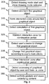
Fig. 3 . This detection is performed e.g. so that a user taps and holds anywhere on adrawing area 410, also referred to as a canvas. The tapping and holding can be either on the canvas background in empty space or on a piece of content. After a first period (e.g. 0.5 to 2 seconds, such as 0.8 seconds), a blue glow is shown beneath the user's finger as adrawing mode indication 420. This is a clear visual indication that the user is now in drawing mode. - It is detected 310 that a user forms a first
graphical object 510. InFig. 5 , with a finger still on the touch screen, the user moves the finger in one motion to draw a freehand line. The drawingmode indication 420 is shown under the user's finger. - In
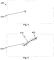
Figs. 5 to 15 , a drawing is used as an example of a graphical object. There are yet many other possibilities provided by different embodiments. The term graphical object may refer to any of: photographs, bitmap drawings, vector drawings, typography, numbers, symbols, maps. The drawings may be freehand drawings. Alternatively or additionally, the drawings may contain computer assisted forms such as lines, arcs, polygons and regression curves. It is also possible to form a graphical object by adding a photograph or other type of stored graphics and then combine other graphics or to add stored graphics to drawn or other stored graphics on the canvas. - An interaction zone is formed 315 around the first
graphical object 510, seezone 520 drawn inFig. 5 .Fig. 6 shows the first graphical object without the drawingmode indication 420 that is no longer shown after the user lifts the finger from thetouch screen 112. In some embodiments, the interaction zone is formed only after completion of the first graphical object as instep 320 ofFig. 3 . In this context, the completion may refer to completing only one phase in forming the first graphical as it is impossible e.g. by thecontrol unit 116 to know if the drawing made by theuser 120 is ready i.e. fully completed or not. Thus, completion may be understood simply as finishing one phase of forming or changing of the firstgraphical object 510. The completion of the adding or changing of the firstgraphical object 510 is determined in one example embodiment from receiving a pause signal from the user. The pause signal is, for instance, the aforementioned lifting of the finger from thetouch screen 112. Other possibilities for producing the pause signal include e.g. releasing a button of a pointing device indicative of a desire to no longer continue the changing or adding of the first graphical object; and pressing a button indicative of a desire to no longer continue the changing or adding of the first graphical object. - The
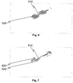
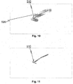
interaction zone 520 is maintained 325 for a given continuation period such as one to five seconds or e.g. two or three seconds. If the user touches the canvas at theinteraction zone 520 during the continuation period, this is determined as a desire to change the firstgraphical object 510. For instance, the user touches the canvas at theinteraction zone 520 as shown by the drawingmode indication 420 inFig. 7 and thecontrol unit 116 detects 330 (Fig. 3 ) that the user desires to change the firstgraphical object 510. The user can then continue drawing on the canvas by moving the finger and thecontrol unit 116changes 335 firstgraphical object 510 according to so given user's instructions. Thus changed firstgraphical object 510 is shown inFig. 8 . The user may keep on changing the firstgraphical object 510 with a result such as that shown inFig. 9 within the continuation period from the most recent change of the first graphical object, as each changing of the firstgraphical object 510 restarts the continuation period. For the time of changing the firstgraphical object 510 the continuation period expiry is not monitored or a respective timer is stopped in one example embodiment. After addition of two more lines, the firstgraphical object 510 now looks like an arrow inFig. 10 . After the continuation period, the interaction zone is cleared 340 (Fig. 3 , see alsoFig. 11 ). - A method of an example embodiment is next shown for erasing a graphical object in part or entirely. See
Figs. 12 and 13 , accessing of a graphical object by the user is detected and the interaction zone is formed around the graphical object,step 345 inFig. 3 . This graphical object is referred to as a first graphical object as the object being manipulated is referred to as the first graphical object. Then a scribble on the first graphical object is detected 350 and the first graphical object is erased to the extent that the scribble covers the first graphical object. Notice that any other graphical objects near the first graphical object are not harmed by the scribble. - Depending on the embodiment, after recognizing that the new changes of the first
graphical object 510 form a scribble, their drawing change either immediately or after the completion of the scribble. In one example, the scribble is detected from at least two lines being drawn back and forth over the first graphical object. Possibly the determining of the scribble may require that the new lines are drawn not only back and forth but also at least partly overlapping with each other. Also it may be determined whether a line starts with an angular difference sufficiently with the end of previous line i.e. if a new line starts to backtrack on a previous line and one or both of these lines cross the firstgraphical object 510.Figs. 14 and 15 illustrate the drawing of a scribble over the firstgraphical object 510 and how a part of the firstgraphical object 510 is responsively erased. If the scribble covers the entire firstgraphical object 510, then the entire firstgraphical object 510 is erased in one example embodiment. - In one example embodiment, the
touch screen 112 is configured to be concurrently operated by a number of users. Two or more graphical objects can then be independently processed as different first graphical objects. If two graphical objects cross or overlap with each other, erasing one of them will not change the other in one example embodiment. Moreover, one example embodiment provides a mechanism for ambiguity resolving in case a user accesses an area in which two or more graphical objects overlap. For instance, the overlapping graphical objects may be selected one by one with successive contacts at the overlapping part and highlighted e.g. by forming a corresponding interaction zone. - In the foregoing, by merging a second graphical object to the first graphical object it may be understood that the first and second graphical objects are grouped into one group of graphical objects. In this document, it is written that the first graphical object is changed by merging the second graphical object therein so that the description of possible subsequent further changes are simpler to describe. This does not mean bridging gaps between an earlier first graphical object and an added new graphical object such as a line when the second graphical object or a new drawing, for instance, is merged to the first graphical object. To the contrary, in one example embodiment, the changed first graphical object is subsequently processed as a grouped object. For instance, the grouping can be canceled by a user at a later point of time. To this end, it may be detected if a user taps the first graphical object when the interaction zone is not present and the user is presented with an option to ungroup the first graphical object. The user may be presented with also some other alternatives such as one or more of the following options: changing color; changing line style; changing line width; inserting a picture; copy the first graphical object onto a clipboard; select the first graphical object; change order of the first graphical object (e.g. move towards front or back); disable scribble erasing feature to enable drawing of a scribble as a new part of the first graphical object; enable scribble erasing feature; and delete the first graphical object.
- Various embodiments have been presented. It should be appreciated that in this document, words comprise, include and contain are each used as open-ended expressions with no intended exclusivity.
- The foregoing description has provided by way of non-limiting examples of particular implementations and embodiments of the invention a full and informative description of the best mode presently contemplated by the inventors for carrying out the invention. It is however clear to a person skilled in the art that the invention is not restricted to details of the embodiments presented above, but that it can be implemented in other embodiments using equivalent means or in different combinations of embodiments without deviating from the characteristics of the invention. For instance, some steps of
Fig. 3 can be omitted, performed a number of times and/or in a different order and further steps can be performed. Further exemplifying, in a multi-user environment, one or more of the steps ofFig. 3 may be performed based on input received from one user while performing any other steps based on input received from the same or another user. - Furthermore, some of the features of the above-disclosed embodiments of this invention may be used to advantage without the corresponding use of other features. As such, the foregoing description shall be considered as merely illustrative of the principles of the present invention, and not in limitation thereof. Hence, the scope of the invention is only restricted by the appended patent claims.
Claims (15)
- An apparatus, comprising:an input configured to receive user instructions for forming graphics in a drawing area based on user instructions;a processor configured to cause:in response to addition or changing of a first graphical object or to completion thereof, forming an interaction zone around the first graphical object for a given continuation period; anddetecting if a second graphical object is drawn starting from within the interaction zone during the continuation period and if yes, changing the first graphical object by merging the second graphical object to the first graphical object.
- The apparatus of claim 1, wherein the processor is configured to form the interaction zone dynamically during the addition or changing of the first graphical object.
- The apparatus of claim 1, wherein the processor is configured to form the interaction zone when the first graphical object is completely added or changed.
- The apparatus of any of preceding claims, further comprising causing displaying of the interaction zone.
- The apparatus of any of preceding claims, wherein the processor is configured to operate in parallel with two or more first graphical objects.
- The apparatus of any of preceding claims, wherein the processor is configured to again cause displaying the interaction zone in response to detecting a re-display command and to erase a portion of the first graphical object in response to detecting drawing of a scribble over the first graphical object.
- A method for forming graphics in a drawing area based on user instructions, comprising:in response to addition or changing of a first graphical object, forming an interaction zone around the first graphical object for a given continuation period; anddetecting if a second graphical object is drawn starting from within the interaction zone during the continuation period and if yes, changing the first graphical object by merging the second graphical object to the first graphical object.
- The method of claim 7, further comprising causing drawing of a new second graphical object after the first graphical object is completely added or changed.
- The method of claim 7 or 8, wherein the interaction zone is formed dynamically during the addition or changing of the first graphical object.
- The method of claim 7 or 8, wherein the interaction zone is formed when the first graphical object is completely added or changed.
- The method of any of claims 7 to 10, further comprising causing displaying of the interaction zone with an appearance differing from the first graphical object.
- The method of any of claims 7 to 11, wherein the interaction zone is formed in response to detecting a user pointing at the first graphical object.
- The method of any of claims 7 to 12, wherein the method is applied in parallel for two or more first graphical objects.
- The method of any of claims 7 to 13, further comprising displaying the interaction zone when the interaction zone is formed and subsequently again displaying the interaction zone in response to detecting a re-displaying command and erasing a portion of the first graphical object in response to detecting drawing of a scribble over the first graphical object.
- A computer program comprising computer executable program code which when executed by at least one processor causes an apparatus to perform the method of any of claims 7 to 14.
Applications Claiming Priority (1)
| Application Number | Priority Date | Filing Date | Title |
|---|---|---|---|
| PCT/FI2012/050538 WO2013178867A1 (en) | 2012-05-31 | 2012-05-31 | User interface for drawing with electronic devices |
Publications (3)
| Publication Number | Publication Date |
|---|---|
| EP2712433A1 EP2712433A1 (en) | 2014-04-02 |
| EP2712433A4 EP2712433A4 (en) | 2014-10-08 |
| EP2712433B1 true EP2712433B1 (en) | 2016-11-02 |
Family
ID=49672527
Family Applications (1)
| Application Number | Title | Priority Date | Filing Date |
|---|---|---|---|
| EP12877781.0A Active EP2712433B1 (en) | 2012-05-31 | 2012-05-31 | User interface for drawing with electronic devices |
Country Status (6)
| Country | Link |
|---|---|
| US (1) | US9323431B2 (en) |
| EP (1) | EP2712433B1 (en) |
| JP (1) | JP5681838B2 (en) |
| CN (1) | CN103765353B (en) |
| IN (1) | IN2014DN00265A (en) |
| WO (1) | WO2013178867A1 (en) |
Families Citing this family (4)
| Publication number | Priority date | Publication date | Assignee | Title |
|---|---|---|---|---|
| JPS58150545A (en) * | 1982-03-03 | 1983-09-07 | Sumitomo Chem Co Ltd | Purification method of 1-aminoanthraquinone |
| CN108491139B (en) * | 2018-02-13 | 2020-12-25 | 广州视源电子科技股份有限公司 | Object fixing method and device, terminal equipment and storage medium |
| JP6840694B2 (en) * | 2018-02-26 | 2021-03-10 | 株式会社日立製作所 | Medical image display device |
| US11464443B2 (en) * | 2019-11-26 | 2022-10-11 | The Chinese University Of Hong Kong | Methods based on an analysis of drawing behavior changes for cognitive dysfunction screening |
Citations (1)
| Publication number | Priority date | Publication date | Assignee | Title |
|---|---|---|---|---|
| WO2008004624A1 (en) * | 2006-07-07 | 2008-01-10 | The University Of Tokyo | Handwritten input processing device, handwritten input processing method, and handwritten input processing program |
Family Cites Families (21)
| Publication number | Priority date | Publication date | Assignee | Title |
|---|---|---|---|---|
| JPH03263281A (en) * | 1990-03-14 | 1991-11-22 | Oki Electric Ind Co Ltd | Handwritten line graphic input device |
| US5404439A (en) | 1992-04-15 | 1995-04-04 | Xerox Corporation | Time-space object containment for graphical user interface |
| US5588100A (en) * | 1992-05-18 | 1996-12-24 | Microsoft Corporation | Method and system for creating a freeform drawing object |
| JPH0721311A (en) * | 1993-06-18 | 1995-01-24 | Oki Electric Ind Co Ltd | On-line character segmenting device |
| JP3353954B2 (en) | 1993-08-13 | 2002-12-09 | ソニー株式会社 | Handwriting input display method and handwriting input display device |
| JP3486876B2 (en) * | 1994-01-28 | 2004-01-13 | ソニー株式会社 | Handwriting input device and method |
| EP0697679A3 (en) * | 1994-08-12 | 1998-07-01 | Dassault Systemes of America | Computerized drawing method |
| JPH08161426A (en) * | 1994-12-09 | 1996-06-21 | Sharp Corp | Handwritten character stroke segmenting device |
| JP3422634B2 (en) * | 1996-08-08 | 2003-06-30 | 株式会社日立製作所 | Handwritten character recognition method and apparatus |
| JP3969775B2 (en) * | 1996-12-17 | 2007-09-05 | キヤノン株式会社 | Handwritten information input device and handwritten information input method |
| JP3216800B2 (en) * | 1997-08-22 | 2001-10-09 | 日立ソフトウエアエンジニアリング株式会社 | Handwritten character recognition method |
| US5889523A (en) | 1997-11-25 | 1999-03-30 | Fuji Xerox Co., Ltd. | Method and apparatus for dynamically grouping a plurality of graphic objects |
| CN1173247C (en) * | 1999-01-13 | 2004-10-27 | 国际商业机器公司 | Hand written information processing system with user's interface for cutting characters |
| US7259752B1 (en) * | 2002-06-28 | 2007-08-21 | Microsoft Corporation | Method and system for editing electronic ink |
| US7949542B2 (en) * | 2005-05-05 | 2011-05-24 | Ionosoft, Inc. | System, method and computer program product for graphically illustrating entities and generating a text-based report therefrom |
| JP2009116824A (en) * | 2007-11-09 | 2009-05-28 | Canon Inc | Drawing/editing system and grouping processing method and program thereof |
| US8698807B2 (en) * | 2008-09-26 | 2014-04-15 | International Business Machines Corporation | Intuitively connecting graphical shapes |
| EP2564298A4 (en) | 2010-04-26 | 2015-05-27 | Smart Technologies Ulc | Method for handling objects representing annotations on an interactive input system and interactive input system executing the method |
| KR101486174B1 (en) * | 2010-08-24 | 2015-01-23 | 노키아 코포레이션 | Method and apparatus for segmenting strokes of overlapped handwriting into one or more groups |
| US9122341B2 (en) | 2010-11-08 | 2015-09-01 | Microsoft Technology Licensing, Llc | Resolving merged touch contacts |
| US20130305172A1 (en) * | 2012-05-10 | 2013-11-14 | Motorola Mobility, Inc. | Pen Tool Editing Modes |
-
2012
- 2012-05-31 CN CN201280042023.8A patent/CN103765353B/en active Active
- 2012-05-31 JP JP2014526527A patent/JP5681838B2/en active Active
- 2012-05-31 US US14/348,045 patent/US9323431B2/en active Active
- 2012-05-31 IN IN265DEN2014 patent/IN2014DN00265A/en unknown
- 2012-05-31 WO PCT/FI2012/050538 patent/WO2013178867A1/en active Application Filing
- 2012-05-31 EP EP12877781.0A patent/EP2712433B1/en active Active
Patent Citations (1)
| Publication number | Priority date | Publication date | Assignee | Title |
|---|---|---|---|---|
| WO2008004624A1 (en) * | 2006-07-07 | 2008-01-10 | The University Of Tokyo | Handwritten input processing device, handwritten input processing method, and handwritten input processing program |
Non-Patent Citations (1)
| Title |
|---|
| TOM MARCAIS: "Google Docs - Create a Drawing", 21 April 2010 (2010-04-21), Retrieved from the Internet <URL:https://youtu.be/Y097HblKru0> [retrieved on 20151210] * |
Also Published As
| Publication number | Publication date |
|---|---|
| JP2014527234A (en) | 2014-10-09 |
| CN103765353B (en) | 2017-07-04 |
| US9323431B2 (en) | 2016-04-26 |
| WO2013178867A1 (en) | 2013-12-05 |
| US20140258898A1 (en) | 2014-09-11 |
| EP2712433A4 (en) | 2014-10-08 |
| CN103765353A (en) | 2014-04-30 |
| IN2014DN00265A (en) | 2015-06-05 |
| JP5681838B2 (en) | 2015-03-11 |
| EP2712433A1 (en) | 2014-04-02 |
Similar Documents
| Publication | Publication Date | Title |
|---|---|---|
| US8413075B2 (en) | Gesture movies | |
| EP2815299B1 (en) | Thumbnail-image selection of applications | |
| US20180074686A1 (en) | Content Relocation on a Surface | |
| JP5449400B2 (en) | Virtual page turning | |
| EP2580643B1 (en) | Jump, checkmark, and strikethrough gestures | |
| JP5658552B2 (en) | Display control apparatus, control method therefor, program, and recording medium | |
| US20050015731A1 (en) | Handling data across different portions or regions of a desktop | |
| US20110283212A1 (en) | User Interface | |
| US9286279B2 (en) | Bookmark setting method of e-book, and apparatus thereof | |
| US10855481B2 (en) | Live ink presence for real-time collaboration | |
| EP2965181B1 (en) | Enhanced canvas environments | |
| EP2712433B1 (en) | User interface for drawing with electronic devices | |
| JP5875262B2 (en) | Display control device | |
| CN113703631A (en) | Writing control method and device, electronic equipment and storage medium | |
| JP6131004B2 (en) | Object display method, program, and apparatus | |
| KR100899035B1 (en) | Electronic board system which use a plural number of display panel and use method | |
| JP6945345B2 (en) | Display device, display method and program | |
| JP6408273B2 (en) | Information processing apparatus, information processing program, and information processing method | |
| JP7490967B2 (en) | DISPLAY CONTROL PROGRAM, DISPLAY CONTROL METHOD, AND DISPLAY CONTROL DEVICE | |
| CN110531902B (en) | Information processing apparatus, information processing method, and recording medium | |
| JP6192793B2 (en) | Object display method, program, and apparatus | |
| CN113918069A (en) | Information interaction method and device, electronic equipment and storage medium | |
| JP2021117766A (en) | Display control program, display control method, and display control device | |
| KR20140067681A (en) | Method and apparatus for applying a document format through touch-screen |
Legal Events
| Date | Code | Title | Description |
|---|---|---|---|
| PUAI | Public reference made under article 153(3) epc to a published international application that has entered the european phase |
Free format text: ORIGINAL CODE: 0009012 |
|
| 17P | Request for examination filed |
Effective date: 20131223 |
|
| AK | Designated contracting states |
Kind code of ref document: A1 Designated state(s): AL AT BE BG CH CY CZ DE DK EE ES FI FR GB GR HR HU IE IS IT LI LT LU LV MC MK MT NL NO PL PT RO RS SE SI SK SM TR |
|
| A4 | Supplementary search report drawn up and despatched |
Effective date: 20140908 |
|
| RIC1 | Information provided on ipc code assigned before grant |
Ipc: G06F 3/0354 20130101AFI20140902BHEP Ipc: G06F 3/0488 20130101ALI20140902BHEP Ipc: G06F 3/041 20060101ALI20140902BHEP Ipc: G06F 3/0484 20130101ALI20140902BHEP Ipc: G06T 11/00 20060101ALI20140902BHEP |
|
| RIN1 | Information on inventor provided before grant (corrected) |
Inventor name: FARSHI, OLIVER Inventor name: ILMONEN, TOMMI |
|
| RIN1 | Information on inventor provided before grant (corrected) |
Inventor name: FARSHI, OLIVER Inventor name: ILMONEN, TOMMI |
|
| 17Q | First examination report despatched |
Effective date: 20150611 |
|
| DAX | Request for extension of the european patent (deleted) | ||
| GRAP | Despatch of communication of intention to grant a patent |
Free format text: ORIGINAL CODE: EPIDOSNIGR1 |
|
| INTG | Intention to grant announced |
Effective date: 20160523 |
|
| GRAS | Grant fee paid |
Free format text: ORIGINAL CODE: EPIDOSNIGR3 |
|
| GRAA | (expected) grant |
Free format text: ORIGINAL CODE: 0009210 |
|
| STAA | Information on the status of an ep patent application or granted ep patent |
Free format text: STATUS: THE PATENT HAS BEEN GRANTED |
|
| AK | Designated contracting states |
Kind code of ref document: B1 Designated state(s): AL AT BE BG CH CY CZ DE DK EE ES FI FR GB GR HR HU IE IS IT LI LT LU LV MC MK MT NL NO PL PT RO RS SE SI SK SM TR |
|
| REG | Reference to a national code |
Ref country code: GB Ref legal event code: FG4D |
|
| REG | Reference to a national code |
Ref country code: AT Ref legal event code: REF Ref document number: 842449 Country of ref document: AT Kind code of ref document: T Effective date: 20161115 Ref country code: CH Ref legal event code: EP |
|
| REG | Reference to a national code |
Ref country code: IE Ref legal event code: FG4D |
|
| REG | Reference to a national code |
Ref country code: DE Ref legal event code: R096 Ref document number: 602012025048 Country of ref document: DE |
|
| PG25 | Lapsed in a contracting state [announced via postgrant information from national office to epo] |
Ref country code: LV Free format text: LAPSE BECAUSE OF FAILURE TO SUBMIT A TRANSLATION OF THE DESCRIPTION OR TO PAY THE FEE WITHIN THE PRESCRIBED TIME-LIMIT Effective date: 20161102 |
|
| REG | Reference to a national code |
Ref country code: NL Ref legal event code: MP Effective date: 20161102 |
|
| REG | Reference to a national code |
Ref country code: LT Ref legal event code: MG4D |
|
| REG | Reference to a national code |
Ref country code: AT Ref legal event code: MK05 Ref document number: 842449 Country of ref document: AT Kind code of ref document: T Effective date: 20161102 |
|
| PG25 | Lapsed in a contracting state [announced via postgrant information from national office to epo] |
Ref country code: GR Free format text: LAPSE BECAUSE OF FAILURE TO SUBMIT A TRANSLATION OF THE DESCRIPTION OR TO PAY THE FEE WITHIN THE PRESCRIBED TIME-LIMIT Effective date: 20170203 Ref country code: LT Free format text: LAPSE BECAUSE OF FAILURE TO SUBMIT A TRANSLATION OF THE DESCRIPTION OR TO PAY THE FEE WITHIN THE PRESCRIBED TIME-LIMIT Effective date: 20161102 Ref country code: SE Free format text: LAPSE BECAUSE OF FAILURE TO SUBMIT A TRANSLATION OF THE DESCRIPTION OR TO PAY THE FEE WITHIN THE PRESCRIBED TIME-LIMIT Effective date: 20161102 Ref country code: NO Free format text: LAPSE BECAUSE OF FAILURE TO SUBMIT A TRANSLATION OF THE DESCRIPTION OR TO PAY THE FEE WITHIN THE PRESCRIBED TIME-LIMIT Effective date: 20170202 Ref country code: NL Free format text: LAPSE BECAUSE OF FAILURE TO SUBMIT A TRANSLATION OF THE DESCRIPTION OR TO PAY THE FEE WITHIN THE PRESCRIBED TIME-LIMIT Effective date: 20161102 |
|
| REG | Reference to a national code |
Ref country code: FR Ref legal event code: PLFP Year of fee payment: 6 |
|
| PG25 | Lapsed in a contracting state [announced via postgrant information from national office to epo] |
Ref country code: IS Free format text: LAPSE BECAUSE OF FAILURE TO SUBMIT A TRANSLATION OF THE DESCRIPTION OR TO PAY THE FEE WITHIN THE PRESCRIBED TIME-LIMIT Effective date: 20170302 Ref country code: RS Free format text: LAPSE BECAUSE OF FAILURE TO SUBMIT A TRANSLATION OF THE DESCRIPTION OR TO PAY THE FEE WITHIN THE PRESCRIBED TIME-LIMIT Effective date: 20161102 Ref country code: PL Free format text: LAPSE BECAUSE OF FAILURE TO SUBMIT A TRANSLATION OF THE DESCRIPTION OR TO PAY THE FEE WITHIN THE PRESCRIBED TIME-LIMIT Effective date: 20161102 Ref country code: AT Free format text: LAPSE BECAUSE OF FAILURE TO SUBMIT A TRANSLATION OF THE DESCRIPTION OR TO PAY THE FEE WITHIN THE PRESCRIBED TIME-LIMIT Effective date: 20161102 Ref country code: FI Free format text: LAPSE BECAUSE OF FAILURE TO SUBMIT A TRANSLATION OF THE DESCRIPTION OR TO PAY THE FEE WITHIN THE PRESCRIBED TIME-LIMIT Effective date: 20161102 Ref country code: ES Free format text: LAPSE BECAUSE OF FAILURE TO SUBMIT A TRANSLATION OF THE DESCRIPTION OR TO PAY THE FEE WITHIN THE PRESCRIBED TIME-LIMIT Effective date: 20161102 Ref country code: PT Free format text: LAPSE BECAUSE OF FAILURE TO SUBMIT A TRANSLATION OF THE DESCRIPTION OR TO PAY THE FEE WITHIN THE PRESCRIBED TIME-LIMIT Effective date: 20170302 Ref country code: HR Free format text: LAPSE BECAUSE OF FAILURE TO SUBMIT A TRANSLATION OF THE DESCRIPTION OR TO PAY THE FEE WITHIN THE PRESCRIBED TIME-LIMIT Effective date: 20161102 |
|
| PG25 | Lapsed in a contracting state [announced via postgrant information from national office to epo] |
Ref country code: CZ Free format text: LAPSE BECAUSE OF FAILURE TO SUBMIT A TRANSLATION OF THE DESCRIPTION OR TO PAY THE FEE WITHIN THE PRESCRIBED TIME-LIMIT Effective date: 20161102 Ref country code: SK Free format text: LAPSE BECAUSE OF FAILURE TO SUBMIT A TRANSLATION OF THE DESCRIPTION OR TO PAY THE FEE WITHIN THE PRESCRIBED TIME-LIMIT Effective date: 20161102 Ref country code: RO Free format text: LAPSE BECAUSE OF FAILURE TO SUBMIT A TRANSLATION OF THE DESCRIPTION OR TO PAY THE FEE WITHIN THE PRESCRIBED TIME-LIMIT Effective date: 20161102 Ref country code: DK Free format text: LAPSE BECAUSE OF FAILURE TO SUBMIT A TRANSLATION OF THE DESCRIPTION OR TO PAY THE FEE WITHIN THE PRESCRIBED TIME-LIMIT Effective date: 20161102 Ref country code: EE Free format text: LAPSE BECAUSE OF FAILURE TO SUBMIT A TRANSLATION OF THE DESCRIPTION OR TO PAY THE FEE WITHIN THE PRESCRIBED TIME-LIMIT Effective date: 20161102 |
|
| REG | Reference to a national code |
Ref country code: DE Ref legal event code: R097 Ref document number: 602012025048 Country of ref document: DE |
|
| PG25 | Lapsed in a contracting state [announced via postgrant information from national office to epo] |
Ref country code: IT Free format text: LAPSE BECAUSE OF FAILURE TO SUBMIT A TRANSLATION OF THE DESCRIPTION OR TO PAY THE FEE WITHIN THE PRESCRIBED TIME-LIMIT Effective date: 20161102 Ref country code: LU Free format text: LAPSE BECAUSE OF NON-PAYMENT OF DUE FEES Effective date: 20170531 Ref country code: SM Free format text: LAPSE BECAUSE OF FAILURE TO SUBMIT A TRANSLATION OF THE DESCRIPTION OR TO PAY THE FEE WITHIN THE PRESCRIBED TIME-LIMIT Effective date: 20161102 Ref country code: BE Free format text: LAPSE BECAUSE OF FAILURE TO SUBMIT A TRANSLATION OF THE DESCRIPTION OR TO PAY THE FEE WITHIN THE PRESCRIBED TIME-LIMIT Effective date: 20161102 Ref country code: BG Free format text: LAPSE BECAUSE OF FAILURE TO SUBMIT A TRANSLATION OF THE DESCRIPTION OR TO PAY THE FEE WITHIN THE PRESCRIBED TIME-LIMIT Effective date: 20170202 |
|
| PLBE | No opposition filed within time limit |
Free format text: ORIGINAL CODE: 0009261 |
|
| STAA | Information on the status of an ep patent application or granted ep patent |
Free format text: STATUS: NO OPPOSITION FILED WITHIN TIME LIMIT |
|
| 26N | No opposition filed |
Effective date: 20170803 |
|
| PG25 | Lapsed in a contracting state [announced via postgrant information from national office to epo] |
Ref country code: SI Free format text: LAPSE BECAUSE OF FAILURE TO SUBMIT A TRANSLATION OF THE DESCRIPTION OR TO PAY THE FEE WITHIN THE PRESCRIBED TIME-LIMIT Effective date: 20161102 |
|
| PG25 | Lapsed in a contracting state [announced via postgrant information from national office to epo] |
Ref country code: MC Free format text: LAPSE BECAUSE OF FAILURE TO SUBMIT A TRANSLATION OF THE DESCRIPTION OR TO PAY THE FEE WITHIN THE PRESCRIBED TIME-LIMIT Effective date: 20161102 |
|
| REG | Reference to a national code |
Ref country code: IE Ref legal event code: MM4A |
|
| PG25 | Lapsed in a contracting state [announced via postgrant information from national office to epo] |
Ref country code: IE Free format text: LAPSE BECAUSE OF NON-PAYMENT OF DUE FEES Effective date: 20170531 |
|
| REG | Reference to a national code |
Ref country code: FR Ref legal event code: PLFP Year of fee payment: 7 |
|
| PG25 | Lapsed in a contracting state [announced via postgrant information from national office to epo] |
Ref country code: MT Free format text: LAPSE BECAUSE OF NON-PAYMENT OF DUE FEES Effective date: 20170531 |
|
| PG25 | Lapsed in a contracting state [announced via postgrant information from national office to epo] |
Ref country code: HU Free format text: LAPSE BECAUSE OF FAILURE TO SUBMIT A TRANSLATION OF THE DESCRIPTION OR TO PAY THE FEE WITHIN THE PRESCRIBED TIME-LIMIT; INVALID AB INITIO Effective date: 20120531 |
|
| PG25 | Lapsed in a contracting state [announced via postgrant information from national office to epo] |
Ref country code: CY Free format text: LAPSE BECAUSE OF NON-PAYMENT OF DUE FEES Effective date: 20161102 |
|
| PG25 | Lapsed in a contracting state [announced via postgrant information from national office to epo] |
Ref country code: MK Free format text: LAPSE BECAUSE OF FAILURE TO SUBMIT A TRANSLATION OF THE DESCRIPTION OR TO PAY THE FEE WITHIN THE PRESCRIBED TIME-LIMIT Effective date: 20161102 |
|
| PG25 | Lapsed in a contracting state [announced via postgrant information from national office to epo] |
Ref country code: TR Free format text: LAPSE BECAUSE OF FAILURE TO SUBMIT A TRANSLATION OF THE DESCRIPTION OR TO PAY THE FEE WITHIN THE PRESCRIBED TIME-LIMIT Effective date: 20161102 |
|
| PG25 | Lapsed in a contracting state [announced via postgrant information from national office to epo] |
Ref country code: AL Free format text: LAPSE BECAUSE OF FAILURE TO SUBMIT A TRANSLATION OF THE DESCRIPTION OR TO PAY THE FEE WITHIN THE PRESCRIBED TIME-LIMIT Effective date: 20161102 |
|
| P01 | Opt-out of the competence of the unified patent court (upc) registered |
Effective date: 20230502 |
|
| PGFP | Annual fee paid to national office [announced via postgrant information from national office to epo] |
Ref country code: FR Payment date: 20230526 Year of fee payment: 12 Ref country code: DE Payment date: 20230519 Year of fee payment: 12 Ref country code: CH Payment date: 20230605 Year of fee payment: 12 |
|
| PGFP | Annual fee paid to national office [announced via postgrant information from national office to epo] |
Ref country code: GB Payment date: 20230524 Year of fee payment: 12 |